

Page 1

OGS 600
Optical guidance sensor
EN 01-2017/11 50137686
We reserve the right
to make technical changes
Original operating instructions
Page 2

© 2017
Leuze electronic GmbH + Co. KG
In der Braike 1
D-73277 Owen / Germany
Phone: +49 7021 573-0
Fax: +49 7021 573-199
http://www.leuze.com
info@leuze.com
Leuze electronic OGS 600
TNT 35/7-24V
Page 3

Table of contents
1 About this document. . . . . . . . . . . . . . . . . . . . . . . . . . . . . . . . . . . . 5
1.1 Explanation of symbols . . . . . . . . . . . . . . . . . . . . . . . . . . . . . . . . . . . . . . . . . . . . . . . . . . . 5
1.2 Terms and abbreviations . . . . . . . . . . . . . . . . . . . . . . . . . . . . . . . . . . . . . . . . . . . . . . . . . . 5
2 Safety . . . . . . . . . . . . . . . . . . . . . . . . . . . . . . . . . . . . . . . . . . . . . . . 6
2.1 Intended use . . . . . . . . . . . . . . . . . . . . . . . . . . . . . . . . . . . . . . . . . . . . . . . . . . . . . . . . . . . 6
2.2 Foreseeable misuse. . . . . . . . . . . . . . . . . . . . . . . . . . . . . . . . . . . . . . . . . . . . . . . . . . . . . . 6
2.3 Competent persons . . . . . . . . . . . . . . . . . . . . . . . . . . . . . . . . . . . . . . . . . . . . . . . . . . . . . . 7
2.4 Exemption of liability . . . . . . . . . . . . . . . . . . . . . . . . . . . . . . . . . . . . . . . . . . . . . . . . . . . . . 7
3 Device description . . . . . . . . . . . . . . . . . . . . . . . . . . . . . . . . . . . . . 8
3.1 Device overview . . . . . . . . . . . . . . . . . . . . . . . . . . . . . . . . . . . . . . . . . . . . . . . . . . . . . . . . . 8
3.2 Performance characteristics . . . . . . . . . . . . . . . . . . . . . . . . . . . . . . . . . . . . . . . . . . . . . . . 9
3.2.1 Trace detection . . . . . . . . . . . . . . . . . . . . . . . . . . . . . . . . . . . . . . . . . . . . . . . . . . . . . . . . . . 9
3.2.2 Measurement time . . . . . . . . . . . . . . . . . . . . . . . . . . . . . . . . . . . . . . . . . . . . . . . . . . . . . . 10
3.2.3 Filter . . . . . . . . . . . . . . . . . . . . . . . . . . . . . . . . . . . . . . . . . . . . . . . . . . . . . . . . . . . . . . . . . 10
3.2.4 Switches . . . . . . . . . . . . . . . . . . . . . . . . . . . . . . . . . . . . . . . . . . . . . . . . . . . . . . . . . . . . . . 10
3.2.5 Faults . . . . . . . . . . . . . . . . . . . . . . . . . . . . . . . . . . . . . . . . . . . . . . . . . . . . . . . . . . . . . . . . 10
3.2.6 Output value . . . . . . . . . . . . . . . . . . . . . . . . . . . . . . . . . . . . . . . . . . . . . . . . . . . . . . . . . . . 11
3.2.7 Example: Guide trace detection with active "Trace width" filter . . . . . . . . . . . . . . . . . . . 13
3.3 Guide trace requirements . . . . . . . . . . . . . . . . . . . . . . . . . . . . . . . . . . . . . . . . . . . . . . . . 14
3.3.1 Trace color . . . . . . . . . . . . . . . . . . . . . . . . . . . . . . . . . . . . . . . . . . . . . . . . . . . . . . . . . . . . 14
3.3.2 Trace width . . . . . . . . . . . . . . . . . . . . . . . . . . . . . . . . . . . . . . . . . . . . . . . . . . . . . . . . . . . . 15
3.3.3 Free space next to the trace . . . . . . . . . . . . . . . . . . . . . . . . . . . . . . . . . . . . . . . . . . . . . . . 15
3.4 Connection technology . . . . . . . . . . . . . . . . . . . . . . . . . . . . . . . . . . . . . . . . . . . . . . . . . . 16
3.5 Operating and display elements . . . . . . . . . . . . . . . . . . . . . . . . . . . . . . . . . . . . . . . . . . . 16
4 Mounting . . . . . . . . . . . . . . . . . . . . . . . . . . . . . . . . . . . . . . . . . . . 17
4.1 General mounting instructions . . . . . . . . . . . . . . . . . . . . . . . . . . . . . . . . . . . . . . . . . . . . 17
4.2 Selecting a mounting location. . . . . . . . . . . . . . . . . . . . . . . . . . . . . . . . . . . . . . . . . . . . . 18
4.3 Mounting accessories . . . . . . . . . . . . . . . . . . . . . . . . . . . . . . . . . . . . . . . . . . . . . . . . . . . 18
5 Electrical connection . . . . . . . . . . . . . . . . . . . . . . . . . . . . . . . . . . 19
5.1 Safety notices for the electrical connection . . . . . . . . . . . . . . . . . . . . . . . . . . . . . . . . . . 19
5.2 Voltage supply . . . . . . . . . . . . . . . . . . . . . . . . . . . . . . . . . . . . . . . . . . . . . . . . . . . . . . . . . 20
5.2.1 Shielding . . . . . . . . . . . . . . . . . . . . . . . . . . . . . . . . . . . . . . . . . . . . . . . . . . . . . . . . . . . . . . 20
5.3 Pin assignment. . . . . . . . . . . . . . . . . . . . . . . . . . . . . . . . . . . . . . . . . . . . . . . . . . . . . . . . . 21
5.3.1 OGS 600-…/D3-M12.8 with RS485 interface. . . . . . . . . . . . . . . . . . . . . . . . . . . . . . . . . . 21
Leuze electronic OGS 600 1
Page 4

Table of contents
5.3.2 OGS 600-…/D2-M12.8 with RS422 interface. . . . . . . . . . . . . . . . . . . . . . . . . . . . . . . . . . 21
5.3.3 OGS 600-…/CN-M12 with CANopen and RS232 interface . . . . . . . . . . . . . . . . . . . . . . . 22
5.4 Switching inputs/outputs . . . . . . . . . . . . . . . . . . . . . . . . . . . . . . . . . . . . . . . . . . . . . . . . 23
5.4.1 Function of the SW_IO and IO switching outputs. . . . . . . . . . . . . . . . . . . . . . . . . . . . . . . 23
5.4.2 Switching output SW_IO (pin 4) . . . . . . . . . . . . . . . . . . . . . . . . . . . . . . . . . . . . . . . . . . . . 25
5.4.3 IO switching output/switching input (pin 2) . . . . . . . . . . . . . . . . . . . . . . . . . . . . . . . . . . . 26
5.4.4 Function of the IO switching input (pin 2) . . . . . . . . . . . . . . . . . . . . . . . . . . . . . . . . . . . . . 27
5.5 Connection to the PC via RS232/RS422/RS485 . . . . . . . . . . . . . . . . . . . . . . . . . . . . . . 28
6 Configuration/diagnostic software . . . . . . . . . . . . . . . . . . . . . . . . 29
6.1 Installing the required software. . . . . . . . . . . . . . . . . . . . . . . . . . . . . . . . . . . . . . . . . . . . 29
6.1.1 System requirements . . . . . . . . . . . . . . . . . . . . . . . . . . . . . . . . . . . . . . . . . . . . . . . . . . . . 29
6.1.2 Installation of the software . . . . . . . . . . . . . . . . . . . . . . . . . . . . . . . . . . . . . . . . . . . . . . . . 29
6.2 Starting the configuration/diagnostic software . . . . . . . . . . . . . . . . . . . . . . . . . . . . . . . 30
6.3 Short description of the configuration/diagnostic software . . . . . . . . . . . . . . . . . . . . . 30
7 Configuring the sensor – Overview of functions . . . . . . . . . . . . . . 31
7.1 Compensating the installation position of the sensor – Angle compensation teach . . 31
7.2 Configuring the guide trace – light, dark, retro-reflective . . . . . . . . . . . . . . . . . . . . . . . 32
7.3 Offset to the edge positions . . . . . . . . . . . . . . . . . . . . . . . . . . . . . . . . . . . . . . . . . . . . . . 33
7.4 Switch. . . . . . . . . . . . . . . . . . . . . . . . . . . . . . . . . . . . . . . . . . . . . . . . . . . . . . . . . . . . . . . . 34
7.4.1 "Switch" function – Settings for type 2 switches . . . . . . . . . . . . . . . . . . . . . . . . . . . . . . . 36
7.4.2 Index accesses for activation of the "Switch" function . . . . . . . . . . . . . . . . . . . . . . . . . . 38
7.5 "Trace width" filter . . . . . . . . . . . . . . . . . . . . . . . . . . . . . . . . . . . . . . . . . . . . . . . . . . . . . . 39
7.5.1 Teaching the trace width . . . . . . . . . . . . . . . . . . . . . . . . . . . . . . . . . . . . . . . . . . . . . . . . . 40
7.5.2 Manual configuration of the trace width . . . . . . . . . . . . . . . . . . . . . . . . . . . . . . . . . . . . . . 40
7.5.3 Process data information for the "Trace width" filter . . . . . . . . . . . . . . . . . . . . . . . . . . . . 40
7.5.4 Index overview for the "Trace width" filter . . . . . . . . . . . . . . . . . . . . . . . . . . . . . . . . . . . . 41
7.6 "Minimum contrast" filter . . . . . . . . . . . . . . . . . . . . . . . . . . . . . . . . . . . . . . . . . . . . . . . . 42
7.6.1 Teaching the minimum contrast . . . . . . . . . . . . . . . . . . . . . . . . . . . . . . . . . . . . . . . . . . . . 42
7.6.2 Manual configuration of the minimum contrast . . . . . . . . . . . . . . . . . . . . . . . . . . . . . . . . 43
7.6.3 Warning for minimum contrast . . . . . . . . . . . . . . . . . . . . . . . . . . . . . . . . . . . . . . . . . . . . . 43
7.6.4 Process data information for the "Minimum contrast" filter . . . . . . . . . . . . . . . . . . . . . . . 43
7.6.5 Index overview for the "Minimum contrast" filter . . . . . . . . . . . . . . . . . . . . . . . . . . . . . . . 44
7.7 "Trace amplitude" filter . . . . . . . . . . . . . . . . . . . . . . . . . . . . . . . . . . . . . . . . . . . . . . . . . . 45
7.7.1 Teaching the trace amplitude . . . . . . . . . . . . . . . . . . . . . . . . . . . . . . . . . . . . . . . . . . . . . . 46
7.7.2 Manual configuration of the trace amplitude . . . . . . . . . . . . . . . . . . . . . . . . . . . . . . . . . . 46
7.7.3 Warning for trace amplitude . . . . . . . . . . . . . . . . . . . . . . . . . . . . . . . . . . . . . . . . . . . . . . . 46
7.7.4 Process data information for the "Trace amplitude" filter . . . . . . . . . . . . . . . . . . . . . . . . 47
Leuze electronic OGS 600 2
Page 5

Table of contents
7.7.5 Index overview for the "Trace amplitude" filter. . . . . . . . . . . . . . . . . . . . . . . . . . . . . . . . . 47
7.8 Index overview – More data on correct and incorrect traces . . . . . . . . . . . . . . . . . . . . 48
8 Commissioning . . . . . . . . . . . . . . . . . . . . . . . . . . . . . . . . . . . . . . . 50
8.1 Communication protocol for serial interfaces (UART) . . . . . . . . . . . . . . . . . . . . . . . . . . 50
8.1.1 RS485/RS422 node address . . . . . . . . . . . . . . . . . . . . . . . . . . . . . . . . . . . . . . . . . . . . . . 50
8.1.2 Error handling . . . . . . . . . . . . . . . . . . . . . . . . . . . . . . . . . . . . . . . . . . . . . . . . . . . . . . . . . . 50
8.1.3 Index access. . . . . . . . . . . . . . . . . . . . . . . . . . . . . . . . . . . . . . . . . . . . . . . . . . . . . . . . . . . 51
8.1.4 Process data. . . . . . . . . . . . . . . . . . . . . . . . . . . . . . . . . . . . . . . . . . . . . . . . . . . . . . . . . . . 53
8.1.4.1 Status byte in the process data . . . . . . . . . . . . . . . . . . . . . . . . . . . . . . . . . . . . . . . . . . . . . . . . . 54
8.1.4.2 Contrast byte in the process data. . . . . . . . . . . . . . . . . . . . . . . . . . . . . . . . . . . . . . . . . . . . . . . . 55
8.1.4.3 Type 1 process data . . . . . . . . . . . . . . . . . . . . . . . . . . . . . . . . . . . . . . . . . . . . . . . . . . . . . . . . . . 56
8.1.4.4 Type 4 process data . . . . . . . . . . . . . . . . . . . . . . . . . . . . . . . . . . . . . . . . . . . . . . . . . . . . . . . . . . 58
8.1.5 Error codes . . . . . . . . . . . . . . . . . . . . . . . . . . . . . . . . . . . . . . . . . . . . . . . . . . . . . . . . . . . . 60
8.2 Object directory for serial interfaces (UART) . . . . . . . . . . . . . . . . . . . . . . . . . . . . . . . . . 61
8.2.1 System commands for serial interfaces . . . . . . . . . . . . . . . . . . . . . . . . . . . . . . . . . . . . . . 65
8.3 CANopen communication protocol . . . . . . . . . . . . . . . . . . . . . . . . . . . . . . . . . . . . . . . . 66
8.3.1 General information on CANopen. . . . . . . . . . . . . . . . . . . . . . . . . . . . . . . . . . . . . . . . . . . 66
8.3.1.1 Topology. . . . . . . . . . . . . . . . . . . . . . . . . . . . . . . . . . . . . . . . . . . . . . . . . . . . . . . . . . . . . . . . . . . 66
8.3.1.2 Bus line (trunk line) . . . . . . . . . . . . . . . . . . . . . . . . . . . . . . . . . . . . . . . . . . . . . . . . . . . . . . . . . . . 66
8.3.1.3 Address assignment . . . . . . . . . . . . . . . . . . . . . . . . . . . . . . . . . . . . . . . . . . . . . . . . . . . . . . . . . . 66
8.3.1.4 Baud rate setting . . . . . . . . . . . . . . . . . . . . . . . . . . . . . . . . . . . . . . . . . . . . . . . . . . . . . . . . . . . . 67
8.3.1.5 Communication mechanisms of the OGS 600 in the CANopen network. . . . . . . . . . . . . . . . . . 68
8.3.1.6 Objects . . . . . . . . . . . . . . . . . . . . . . . . . . . . . . . . . . . . . . . . . . . . . . . . . . . . . . . . . . . . . . . . . . . . 68
8.3.1.7 EDS file . . . . . . . . . . . . . . . . . . . . . . . . . . . . . . . . . . . . . . . . . . . . . . . . . . . . . . . . . . . . . . . . . . . . 69
8.3.1.8 SDOs and PDOs . . . . . . . . . . . . . . . . . . . . . . . . . . . . . . . . . . . . . . . . . . . . . . . . . . . . . . . . . . . . . 69
8.3.1.9 Default 11 bit identifier . . . . . . . . . . . . . . . . . . . . . . . . . . . . . . . . . . . . . . . . . . . . . . . . . . . . . . . . 71
8.3.1.10 Object structure of the OGS 600 . . . . . . . . . . . . . . . . . . . . . . . . . . . . . . . . . . . . . . . . . . . . . . . . 72
8.3.1.11 Process data objects . . . . . . . . . . . . . . . . . . . . . . . . . . . . . . . . . . . . . . . . . . . . . . . . . . . . . . . . . 73
8.3.1.12 Overview of the mapped data in the TxPDOs. . . . . . . . . . . . . . . . . . . . . . . . . . . . . . . . . . . . . . . 74
8.3.1.13 Overview of the mapped data in the RxPDO . . . . . . . . . . . . . . . . . . . . . . . . . . . . . . . . . . . . . . . 75
8.3.1.14 Overview TPDOs. . . . . . . . . . . . . . . . . . . . . . . . . . . . . . . . . . . . . . . . . . . . . . . . . . . . . . . . . . . . . 76
8.3.1.15 Overview RPDOs . . . . . . . . . . . . . . . . . . . . . . . . . . . . . . . . . . . . . . . . . . . . . . . . . . . . . . . . . . . . 78
8.4 CANopen object directory . . . . . . . . . . . . . . . . . . . . . . . . . . . . . . . . . . . . . . . . . . . . . . . . 79
8.4.1 CANopen system commands. . . . . . . . . . . . . . . . . . . . . . . . . . . . . . . . . . . . . . . . . . . . . . 83
8.5 Performing a reset on the OGS 600 . . . . . . . . . . . . . . . . . . . . . . . . . . . . . . . . . . . . . . . . 83
9 Tips for initial commissioning . . . . . . . . . . . . . . . . . . . . . . . . . . . . 84
9.1 Configuration of the sensor according to the trace . . . . . . . . . . . . . . . . . . . . . . . . . . . . 84
9.1.1 Variant: All filters ON . . . . . . . . . . . . . . . . . . . . . . . . . . . . . . . . . . . . . . . . . . . . . . . . . . . . . 84
9.1.2 Changeover between different traces. . . . . . . . . . . . . . . . . . . . . . . . . . . . . . . . . . . . . . . . 85
9.1.3 Trace markings for application-specific actions . . . . . . . . . . . . . . . . . . . . . . . . . . . . . . . . 85
9.2 Basic settings for the filters. . . . . . . . . . . . . . . . . . . . . . . . . . . . . . . . . . . . . . . . . . . . . . . 86
Leuze electronic OGS 600 3
Page 6

Table of contents
10 Service and support . . . . . . . . . . . . . . . . . . . . . . . . . . . . . . . . . . . 87
10.1 Decommissioning, maintenance . . . . . . . . . . . . . . . . . . . . . . . . . . . . . . . . . . . . . . . . . . . 87
10.2 Contact. . . . . . . . . . . . . . . . . . . . . . . . . . . . . . . . . . . . . . . . . . . . . . . . . . . . . . . . . . . . . . . 87
11 Technical data . . . . . . . . . . . . . . . . . . . . . . . . . . . . . . . . . . . . . . . 88
11.1 General technical data OGS 600 . . . . . . . . . . . . . . . . . . . . . . . . . . . . . . . . . . . . . . . . . . . 88
11.2 Dimensioned drawings . . . . . . . . . . . . . . . . . . . . . . . . . . . . . . . . . . . . . . . . . . . . . . . . . . 89
11.2.1 Dimensioned drawing OGS 600-280/CN-M12 – long version . . . . . . . . . . . . . . . . . . . . . 89
11.2.2 Dimensioned drawing OGS 600-280/D…-M12.8 – long version . . . . . . . . . . . . . . . . . . . 90
11.2.3 Dimensioned drawing OGS 600-140/CN-M12 – short version . . . . . . . . . . . . . . . . . . . . 91
11.2.4 Dimensioned drawing OGS 600-140/D…-M12.8 – short version. . . . . . . . . . . . . . . . . . . 92
11.3 Diagrams . . . . . . . . . . . . . . . . . . . . . . . . . . . . . . . . . . . . . . . . . . . . . . . . . . . . . . . . . . . . . 93
11.3.1 Sensor characteristic curve with one guide trace. . . . . . . . . . . . . . . . . . . . . . . . . . . . . . . 93
11.3.2 Linearity error . . . . . . . . . . . . . . . . . . . . . . . . . . . . . . . . . . . . . . . . . . . . . . . . . . . . . . . . . . 94
12 Order guide and accessories . . . . . . . . . . . . . . . . . . . . . . . . . . . . 95
12.1 Sensor part number code . . . . . . . . . . . . . . . . . . . . . . . . . . . . . . . . . . . . . . . . . . . . . . . . 95
12.2 Order guide for sensor. . . . . . . . . . . . . . . . . . . . . . . . . . . . . . . . . . . . . . . . . . . . . . . . . . . 95
12.3 Accessories . . . . . . . . . . . . . . . . . . . . . . . . . . . . . . . . . . . . . . . . . . . . . . . . . . . . . . . . . . . 96
12.3.1 Connection cables for CANopen/RS232 devices. . . . . . . . . . . . . . . . . . . . . . . . . . . . . . . 96
12.3.2 Connection cables for RS485/RS422 devices . . . . . . . . . . . . . . . . . . . . . . . . . . . . . . . . . 97
12.3.3 RS485-USB adapter set . . . . . . . . . . . . . . . . . . . . . . . . . . . . . . . . . . . . . . . . . . . . . . . . . . 97
12.3.4 Guide trace tapes, self-adhesive . . . . . . . . . . . . . . . . . . . . . . . . . . . . . . . . . . . . . . . . . . . 97
13 Appendix – Sensor measurement values for RAL colors . . . . . . . . 98
Leuze electronic OGS 600 4
Page 7

1 About this document
This technical description contains information regarding the proper use of the OGS 600
optical guidance sensors.
1.1 Explanation of symbols
The symbols used in this technical description are explained below.
CAUTION
This symbol precedes text messages which must strictly be observed.
Failure to observe the provided instructions could lead to personal injury or damage to
equipment.
NOTE
This symbol indicates text passages containing important information.
1.2 Terms and abbreviations
AGV Automated Guided Vehicle
DTM Device Type Manager
EMC Electromagnetic compatibility
EN European standard
FDT Field Device Tool
FE Functional earth
GUI Graphical User Interface
IO or I/O Input/Output
OGS Optical Guidance Sensor
PD Process data
RO Read Only
RW Read/Write
PLC Programmable Logic Control
UART Universal Asynchronous Receiver Transmitter, here: RS232 / RS422 / RS485
WO Write Only
Table 1.1: Terms and abbreviations
About this document
TNT 35/7-24V
Leuze electronic OGS 600 5
Page 8

2 Safety
This sensor was developed, manufactured and tested in line with the applicable safety standards. It corresponds to the state of the art.
2.1 Intended use
The OGS 600 optical guidance sensor measures the contrast of a guide trace that is affixed
to the ground. The sensor supplies the vehicle's position data on the guide trace, which
determines the course of travel.
Areas of application
The OGS 600 optical guidance sensor is designed for the following area of application:
• Intralogistics – in-house material flow with automated guided vehicles (AGV).
CAUTION
Observe intended use!
The protection of personnel and the device cannot be guaranteed if the device is operated in a manner not complying with its intended use.
Only operate the device in accordance with its intended use.
Leuze electronic GmbH + Co. KG is not liable for damages caused by improper use.
Read the supplement and these operating instructions for the device before commis-
sioning the device. Knowledge of these documents is required in order to use the
equipment for its intended purpose.
Safety
NOTE
The optical guidance sensors of the OGS 600 series correspond to the following classification with respect to the integrated lighting:
Illumination red:
risk group 0 (exempt group) in acc. with EN 62471
NOTE
Comply with conditions and regulations!
Observe the locally applicable legal regulations and the rules of the employer's liability
insurance association.
2.2 Foreseeable misuse
Any use other than that defined under "Intended use" or which goes beyond that use is
considered improper use.
Leuze electronic OGS 600 6
TNT 35/7-24V
Page 9

In particular, use of the device is not permitted in the following cases:
• in rooms with explosive atmospheres
• as stand-alone safety component in accordance with the machinery directive
• for medical purposes
NOTE
Do not modify or otherwise interfere with the device!
Do not carry out modifications or otherwise interfere with the device.
The device must not be tampered with and must not be changed in any way.
The device must not be opened. There are no user-serviceable parts inside.
Repairs must only be performed by Leuze electronic GmbH + Co. KG.
2.3 Competent persons
Connection, mounting, commissioning and adjustment of the device must only be carried
out by competent persons.
Prerequisites for competent persons:
• They have a suitable technical education.
• They are familiar with the rules and regulations for occupational safety and safety at
work.
• They are familiar with the original operating instructions of the device.
• They have been instructed by the responsible person on the mounting and operation
of the device.
Safety
1)
Certified electricians
Electrical work must be carried out by a certified electrician.
Due to their technical training, knowledge and experience as well as their familiarity with
relevant standards and regulations, certified electricians are able to perform work on electrical systems and independently detect possible dangers.
In Germany, certified electricians must fulfill the requirements of accident-prevention regulations BGV A3 (e.g. electrician foreman). In other countries, there are respective regulations that must be observed.
2.4 Exemption of liability
Leuze electronic GmbH + Co. KG is not liable in the following cases:
• The device is not being used properly.
• Reasonably foreseeable misuse is not taken into account.
• Mounting and electrical connection are not properly performed.
• Changes (e.g., constructional) are made to the device.
1) Use as a safety-related component within a safety function is not permissible.
Leuze electronic OGS 600 7
TNT 35/7-24V
Page 10

3 Device description
A Integrated illumination – transmitter (small lenses)
B Receiver modules – receiver (large lenses)
C Groove with 2 sliding blocks for fastening the mounting bracket
D 2 x M12 connector, 5-pin
E 1 x M12 connector, 8-pin
A
B
C
D
OGS 600-280/CN-M12
OGS 600-140/D…-M12.8
E
3.1 Device overview
Device description
Leuze electronic OGS 600 8
Figure 3.1: Device overview
TNT 35/7-24V
Page 11

3.2 Performance characteristics
A
B
C
D
E
A Guide trace; here dark trace on light background
B Left edge of guide trace
C Right edge of guide trace
D Width of the sensor's measurement field
E AGV direction of travel
3.2.1 Trace detection
The sensor is designed to detect an optical guide trace on the floor and to output the position
of the guide trace relative to the sensor.
The sensor can detect a light trace on a dark background or, inversely, a dark trace on a
light background.
The sensor can detect up to 6 guide traces. Each guide trace consists of a left edge (shown
in red below) and a right edge (show in green below). This edge information is output for
each detected guide trace.
When a guide trace is detected, the sensor therefore outputs two pieces of information in
the process data for each trace:
• position of the left edge of the guide trace and
• position of the right edge of the guide trace
The difference between these two edge positions is the track width.
Device description
Figure 3.2: Schematic illustration of the guide trace under the optical guidance sensor
Leuze electronic OGS 600 9
TNT 35/7-24V
Page 12

3.2.2 Measurement time
The sensor delivers an updated measurement every 10ms.
3.2.3 Filter
The detection of incorrect floor markings can be minimized considerably by means of the
following filters, which can be activated separately: trace width, minimum contrast and trace
amplitude.
Filtered-out traces can be read out in separate parameters (see the chapter "Index overview
– More data on correct and incorrect traces").
Chapter 9 "Tips for initial commissioning" contains information on using the filters.
3.2.4 Switches
At each switch, the sensor outputs two or more traces. The users themselves decide which
trace they want to follow. The switch function is provided to ensure that the wide midpoint of
the type 2 switch (see chapter 7.4 "Switch") is detected properly when the trace width filter
is active.
Example:
When the vehicle moves over a seamlessly bonded switch (type 2) and a turn request is
given, the vehicle control unit can very early on follow the edge position in the direction in
which the vehicle is to turn.
If the vehicle is to turn left, the vehicle is guided by the left edge. The turn operation then
begins before the sensor has passed the midpoint of the switch and outputs two traces.
Device description
3.2.5 Faults
If floor markings occur which, despite activated filters, are detected as valid, then these
markings are output. The vehicle's control unit must ensure that position jumps in the output
traces are detected and that they are not followed.
Leuze electronic OGS 600 10
TNT 35/7-24V
Page 13

3.2.6 Output value
150 mm
17 mm 17 mm
AB
A Start of measurement field, output value 0
B End of measurement field, output value 1500 or 3000
300 mm
17 mm 17 mm
AB
The sensor outputs the position of the left edge and the right edge of the optical guide trace
in mm * 10. The output value range is therefore:
• Short version OGS 600-140…: 0 … 1500.
•Long version OGS 600-280…: 0 … 3000.
A trace is detected if it enters the sensor's measurement field by at least 17mm at the
left or right edge. This corresponds to an output value of:
• Short version OGS 600-140…: 170 … 1330.
•Long version OGS 600-280…: 170 … 2830.
Device description
Figure 3.3: Measurement field of the guidance sensor
The trace width is the absolute value of the difference between the right and left edge of the
trace.
Leuze electronic OGS 600 11
TNT 35/7-24V
Page 14
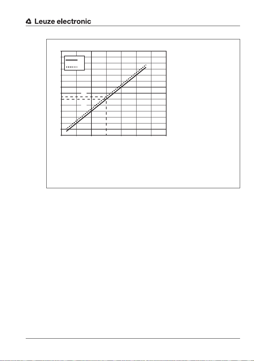
3500
A Measurement value for left edge of guide trace
B Measurement value for right edge of guide trace
C Output value: Position of left edge
D Output value: Position of right edge
x Position of left edge of guide trace under sensor
y Output value: Edge positions
3000
2500
2000
1500
1000
500
Device description
y
A
B
D
C
0
0 10050 150 200 250 300 350
Figure 3.4: Sensor characteristic curve with one trace (long version)
x
TNT 35/7-24V
Leuze electronic OGS 600 12
Page 15

Device description
A
B
C
D
A Guide trace; here dark trace on light background
B Left edge of guide trace
C Right edge of guide trace
D, E Trace too wide according to active "Trace width" filter
F Width of the sensor's measurement field
G AGV direction of travel
H Objects not detected as trace
G
E
F
F
H
H
If the "Trace width" filter detects an excessively wide trace, you can e.g.:
• activate the "Switch" function
• manually increase the upper tolerance for
the permissible trace width
3.2.7 Example: Guide trace detection with active "Trace width" filter
Leuze electronic OGS 600 13
Figure 3.5: Schematic illustration of the guide trace under the optical guidance sensor
TNT 35/7-24V
Page 16

3.3 Guide trace requirements
To ensure error-free detection of the optical guide trace on the floor, the guide trace must
meet the requirements described in the following sections.
3.3.1 Trace color
The illumination of the sensors emits red light. As a result, the contrast that the sensor sees
is different to that perceived by the human eye.
The following overview shows how the sensor sees different colors.
Device description
Color perceived by
human eye
White Traffic white 9016 21200 Leuze black
Black Jet black 9005 400 Leuze white 1)
Red Tomato red 3013 11800 Black
Orange Deep orange 2011 17400 Black
Yellow Melon yellow 1028 19800 Black
Green Emerald green 6001 1200 White
Blue Ultramarine blue 5002 700 White
1) Leuze trace tapes available as accessories:
OTB 40-BK250, black, 40mm wide, self-adhesive, 25m roll (part no. 50137874)
OTB 40-WH250, white, 40mm wide, self-adhesive, 25m roll (part no. 50137875)
Table 3.6: Color comparison between the sensor and the human eye.
NOTE
A detailed table with sensor measurement values can be found in the appendix (see
chapter 13 "Appendix – Sensor measurement values for RAL colors").
Floor/background Guide trace
RAL color RAL no. Measurement value of
the sensor:
Amplitude [LSB]
Suitable
trace color
1)
TNT 35/7-24V
Leuze electronic OGS 600 14
Page 17

3.3.2 Trace width
AB
C
A Guide trace; here dark trace on light background
B Free space next to guide trace
C Markings next to guide trace
B
C
The maximum width of the trace is limited only by the sensor's measurement field (see
figure 3.3). The trace must have a minimum width so that a sufficiently good contrast can be
achieved. The "Trace width" filter can be adjusted to the trace by means of a trace width
teach.
The recommended trace width is approx. 30 … 40mm.
Trace width OGS 600-280… OGS 600-140…
Maximum 266mm 106mm
Minimum 20mm 20mm
Table 3.1: Maximum/minimum trace widths
3.3.3 Free space next to the trace
To ensure error-free detection, there should not be any other marking within a distance of at
least 30mm from the actual trace.
At distances greater than 30mm from the trace, the floor can have any color.
> 30mm > 30mm
Device description
Leuze electronic OGS 600 15
Figure 3.7: Minimum distance between the guide trace and other objects on the floor
The same applies to an inverted layout with a light guide trace on a dark background.
TNT 35/7-24V
Page 18

3.4 Connection technology
All device connections are based on M12 connection technology, see chapter 5 "Electrical
connection".
NOTE
Shielding!
The shielding is connected via the M12 connector housing.
Use only shielded connection cables!
3.5 Operating and display elements
The optical guidance sensor does not have any operating elements or indicators.
The sensor is operated and its configuration checked only via the serial interface or via the
CAN bus.
Device description
Leuze electronic OGS 600 16
TNT 35/7-24V
Page 19

4 Mounting
20°
A
B
C
A Optical guidance sensor
B Reflection of reflecting surfaces
C Automated guided vehicle (AGV)
D Direction of travel
D
4.1 General mounting instructions
The device is mounted using the groove integrated in the profile. Two sliding blocks with M6
thread are included in the delivery and already inserted into the groove.
NOTE
Mount the sensor at an angle!
The sensor must be mounted at an angle of 20° to ensure that reflective surfaces have no
effect on the evaluation.
Mounting
Figure 4.1: Angled sensor mounting to prevent unwanted reflection
The sensor can be mounted using the mounting brackets included in the delivery (see
chapter 4.3 "Mounting accessories"). They ensure that the sensor is pointing at the floor at
the correct angle.
Leuze electronic OGS 600 17
TNT 35/7-24V
Page 20

4.2 Selecting a mounting location
Reliable detection of the guide trace primarily depends on how good the contrast is between
the trace and the background.
In order to select the right mounting location, several factors must be considered:
• The distance of the sensor to the trace to be detected should be 10 … 70mm.
• The guide trace must have a minimum width of 20mm.
• The linearity error of the output value depends on the distance to the floor.
• Diffuse reflection of the trace. Ideally, a jet black guide trace on a pure white background should be used.
4.3 Mounting accessories
The following items are included with the sensor:
• 2x M6 sliding blocks (inserted in the groove)
• 2x mounting brackets for mounting the sensor at an angle of 20°.
NOTE
Dimensioned drawings!
The dimensioned drawings with the installation dimensions of the sensor can be found in
Chapter 11.2.
Mounting
Leuze electronic OGS 600 18
TNT 35/7-24V
Page 21

5 Electrical connection
NOTE
The corresponding mating connectors and ready-made cables are available as accessories for all M12 connections. For further information, see chapter 12 "Order guide and
accessories".
5.1 Safety notices for the electrical connection
CAUTION
Before connecting the device, be sure that the supply voltage agrees with the value
printed on the name plate.
The device may only be connected by a qualified electrician.
Ensure that the functional earth (FE) is connected correctly. Unimpaired operation is
only guaranteed when the functional earth is connected properly.
If faults cannot be cleared, the device should be switched off and protected against
accidental use.
NOTE
Protective Extra Low Voltage (PELV)!
The OGS 600 optical guidance sensors are designed in accordance with protection class
III for supply by PELV (protective extra-low voltage with reliable disconnection).
Electrical connection
NOTE
Shielding connection!
The shielding is connected via the M12 connector housing.
Use only shielded connection cables!
NOTE
Degree of protection IP65 is achieved only if the connectors and caps are screwed into
place.
Leuze electronic OGS 600 19
TNT 35/7-24V
Page 22

5.2 Voltage supply
The OGS 600 guidance sensors are designed for a voltage supply of 18 … 30 VDC (PELV
– protective extra low voltage with reliable disconnection). The current consumption with
24 V DC is approx. 180 mA.
5.2.1 Shielding
NOTE
Shielded connection cables!
Only shielded connection cables should be used; they ensure that the housing of the
OGS 600 is connected to functional earth.
Use only shielded connection cables!
The shielding must be connected to earth potential on the connection side.
If unshielded connection cables are used, a separate cable must be routed from the
housing to the earth potential (additional earthing screw on the housing cover and in
the fastening groove).
Electrical connection
Leuze electronic OGS 600 20
TNT 35/7-24V
Page 23

5.3 Pin assignment
M12 plug
(A-coded)
M12 plug
(A-coded)
5.3.1 OGS 600-…/D3-M12.8 with RS485 interface
PWR/RS485, 8-pin M12 connector, A-coded
Pin Name Comment IN / OUT
1 VIN Operating voltage +18 … +30V DC IN
2 IO Switching input or switching output IN / OUT
3GND
4 SW_IO Switching output OUT
5 RX / TX + Signal line of RS485 interface IN / OUT
6 RX / TX - Signal line of RS485 interface IN / OUT
7 n. c. Not connected
8 n. c. Not connected
Thread FE Functional earth (housing)
Table 5.1: PWR/RS485 – Pin assignment for OGS 600 with RS485 interface
5.3.2 OGS 600-…/D2-M12.8 with RS422 interface
PWR/RS422, 8-pin M12 connector, A-coded
Pin Name Comment IN / OUT
1 VIN Operating voltage +18 … +30 VDC IN
2 IO Switching input or switching output IN / OUT
3GND
4 SW_IO Switching output OUT
5 TX + Signal line of RS422 interface OUT
6 TX- Signal line of RS422 interface OUT
7 RX + Signal line of RS422 interface IN
8 RX- Signal line of RS422 interface IN
Thread FE Functional earth (housing)
Table 5.2: PWR/RS422 – Pin assignment for OGS 600 with RS422 interface
Operating voltage 0VDC / reference
Operating voltage 0VDC / reference
Electrical connection
ground
ground
IN
IN
TNT 35/7-24V
Leuze electronic OGS 600 21
Page 24

Electrical connection
M12 plug
(A-coded)
M12 socket
(A-coded)
5.3.3 OGS 600-…/CN-M12 with CANopen and RS232 interface
PWR/RS232, 5-pin M12 connector, A-coded
Pin Name Comment IN / OUT
1 VIN Operating voltage +18 … +30 VDC IN
2 RxD Signal line of RS232 interface IN
3GND
4 SW_IO Switching output OUT
5 TxD Signal line of RS232 interface OUT
Thread FE Functional earth (housing)
Table 5.3: PWR/RS232 – Pin assignment for OGS 600 with CANopen/RS232 interface
CAN, 5-pin M12 socket, A-coded
Pin Name Comment IN / OUT
1 SHIELD CAN functional earth
2 n. c. Not connected
3 CAN_GND Reference level for CAN signal lines
4 CAN_High CAN bus A signal line IN / OUT
5 CAN_Low CAN bus B signal line IN / OUT
Thread FE Functional earth (housing)
Operating voltage 0VDC / reference
ground
IN
Table 5.4: CAN – Pin assignment for OGS 600 with CANopen/RS232 interface
Leuze electronic OGS 600 22
TNT 35/7-24V
Page 25

5.4 Switching inputs/outputs
NOTE
The devices with RS485 and RS422 interface have two IO pins:
• SW_IO (pin 4) switching output (configurable)
• IO (pin 2) switching input or switching output (configurable)
The devices with CANopen and RS232 interface have only one IO pin:
• SW_IO (pin 4) switching output (configurable)
5.4.1 Function of the SW_IO and IO switching outputs
The switching outputs are configured via index accesses only. The possible function range
is the same for both switching outputs. The switching outputs can be configured independently of each other.
Two functions are available which can be signaled via the switching output.
Trace monitoring
An upper and lower position value can be defined using two parameters. The limit values
are compared with the values of the detected trace.
If the left or the right edge of the detected trace is greater than the limit value, the switching
output is activated.
If more than one trace is detected, then the outermost edges are always used for monitoring.
The function has a hysteresis.
Electrical connection
Contrast monitoring
An upper and a lower value can be defined for contrast using two parameters. The limit
values are compared internally with the values of the contrast measured for the current
trace.
If the contrast is greater or less than the limit value, the switching output is activated.
NOTE
Deactivation of a switching output
Both switching outputs SW_IO and IO can also be deactivated independently of each
other.
Leuze electronic OGS 600 23
TNT 35/7-24V
Page 26

Switching behavior
1 High signal within switching points
2 High signal outside switching points
3 Hysteresis
4 Measurement value: object position or contrast
5 Upper switching point
6 Lower switching point
ON
1
OFF
ON
2
OFF
Electrical connection
3
6 5 4
Figure 5.1: Switching behavior of the switching outputs
NOTE
The switching outputs can be configured independently of each other as:
• Push-pull switching output
•PNP switching output
• NPN switching output
Leuze electronic OGS 600 24
TNT 35/7-24V
Page 27

5.4.2 Switching output SW_IO (pin 4)
The functions of the switching output are described in Chapter 5.4.1.
The switching output SW_IO is connected to pin 4 on all device models (see chapter 5.3
"Pin assignment"). The function of the switching output can be configured via indices.
Electrical connection
Name Index
Q1UserConfig 87d 2003h [6h]2 RW 0d 0d: not active
Q1SwitchPtMode 80
Q1UpperSwitchingPoint 77
Q1LowerSwitchingPoint 78
Q1Hysteresis 81
Q1LightDark 79
Qproperty 76
Index
UART
[subindex]
CANopen
2003h [4h]2 RW 0d 0d: deactivated
d
2003h [1h]2 RW 0d Upper limit.
d
2003h [2h]2 RW 0d Lower limit.
d
2003h [5h]2 RW 20d Hysteresis in absolute values.
d
2003h [3h]2 RW 0d 0d: output has high signal outside switching
d
2005h [0h]2 RW 0d 0d: switching output switches OFF
d
Index
length
[byte]
Access Default
data
Function / value [dec.]
1
: Out_PP (push-pull)
d
2
: Out_NPN
d
3
: Out_PNP
d
1
: trace monitoring
d
2
: contrast monitoring
d
Trace position in mm * 10
Contrast value in LSB
Trace position in mm * 10
Contrast value in LSB
Applies to both limits.
Unit: mm * 10 or LSB
points
1
: output has high signal within switching
d
points
1
: switching output switches ON
d
2
: switching output remains unchanged
d
Takes effect in the case of
• Activation/deactivation
• Global error
(UART index 200
], value 0001h) with detailed info in UART
[1
h
index 201
Table 5.5: Configuration options for switching output SW_IO (pin 4)
, and CAN index 2020h
d
and CAN index 2020h [2h]
d
TNT 35/7-24V
Leuze electronic OGS 600 25
Page 28

5.4.3 IO switching output/switching input (pin 2)
The functions of the switching output are described in Chapter 5.4.1.
The IO switching output is connected to pin 2 on the device models with RS485 and RS422
interface (see chapter 5.3 "Pin assignment"). The function of the switching output can be
configured via indices.
Electrical connection
Name Index
Q2UserConfig 88
Q2SwitchPtMode 85
Q2UpperSwitchingPoint 82
Q2LowerSwitchingPoint 83
Q2Hysteresis 86
Q2LightDark 84
Qproperty 76
Index
UART
[subindex]
CANopen
2004h [6h]2 RW 0d 0h: inactive
d
2004h [4h]2 RW 0d 0d: deactivated
d
2004h [1h]2 RW 0d Upper limit.
d
2004h [2h]2 RW 0d Lower limit.
d
2004h [5h]2 RW 20d Hysteresis in absolute values.
d
2004h [3h]2 RW 0d 0d: output has high signal outside switching
d
2005h [0h]2 RW 0d 0d: switching output switches OFF
d
Index
length
[byte]
Access Default
data
Function / value [dec.]
1
: Out_PP (push-pull)
h
2
: Out_NPN
h
3
: Out_PNP
h
104
: In_NPN deactivation input
h
105
: In_PNP deactivation input
h
304
: In_NPN activation input
h
305
: In_PNP activation input
h
1
: trace monitoring
d
2
: contrast monitoring
d
Trace position in mm * 10
Contrast value in LSB
Trace position in mm * 10
Contrast value in LSB
Applies to both limits.
Unit: mm * 10 or LSB
points
1
: output has high signal within switching
d
points
1
: switching output switches ON
d
2
: switching output remains unchanged
d
Takes effect in the case of
• Activation/deactivation
• Global error
(UART index 200
], value 0001h) with detailed info in UART
[1
h
index 201
d
Table 5.6: Configuration options IO switching output/switching input (pin 2)
, and CAN index 2020h
d
and CAN index 2020h [2h]
TNT 35/7-24V
Leuze electronic OGS 600 26
Page 29

5.4.4 Function of the IO switching input (pin 2)
The switching input is configured via index accesses only (see Table 5.6).
Two functions are available which can be activated via the switching input.
Activation
A high signal at the switching input activates the sensor illumination; a low signal deactivates
the sensor illumination.
Deactivation
A high signal at the switching input deactivates the sensor illumination; a low signal activates
the sensor illumination.
NOTE
Output behavior with deactivated sensor illumination
With the sensor illumination deactivated, the sensor does not deliver any measurement
values.
In this case, the output behavior of the switching output (pin 2, pin 4) with the trace monitoring or contrast monitoring function can be controlled via UART index 76
index 2005
This setting has no effect on the output of process data.
NOTE
Deactivation of the switching input
The switching input IO can also be deactivated.
) Qproperty.
h
Electrical connection
(CANopen
d
Leuze electronic OGS 600 27
TNT 35/7-24V
Page 30

5.5 Connection to the PC via RS232/RS422/RS485
A
B
C
A PC with OGS 600 software
B RS485-USB adapter (on request)
C Y-connection cable (on request)
D Optical guidance sensor
D
The devices can be configured via the RS232/RS422/RS485 interface using the Windows
software OGS600.exe or Sensor Studio.
All connections via the serial interfaces require a USB adapter which provides a virtual COM
port on the PC.
For the RS422/RS485 interface, a USB adapter and a Y-cable are available as accessories
for setting up the connection between the sensor, voltage supply and USB adapter.
Electrical connection
Figure 5.2: Connection of the OGS 600 to the PC using the RS485 interface
The adapter set and the Y-connection cable are available as accessories on request.
Information about installation and use of the software can be found in Chapter 6 "Configu-
Leuze electronic OGS 600 28
ration/diagnostic software" on page 29.
TNT 35/7-24V
Page 31

Configuration/diagnostic software
6 Configuration/diagnostic software
6.1 Installing the required software
6.1.1 System requirements
Operating system: Windows XP
Windows Vista
Windows 7
Windows 8
Windows 10
Computer: PC with USB interface version 1.1 or higher
Graphics card: Min. 1024 x 768 pixels or higher resolution
Required hard drive capacity: Approx. 10MB
Note!
It is recommended to update the operating system and the browser regularly and to install
the current Windows service packs.
6.1.2 Installation of the software
RS485-USB adapter
A driver must be installed for the USB RS485/422 interface adapter (available as an accessory). It can be found on the supplied CD. The file CDM21216_Setup.exe can be found on
the CD in the folder ..\Windows. This file must be executed by double-clicking. Admin rights
are required for correct installation.
Configuration software OGS 600
The control software for the OGS 600 does not need to be installed. This is a directly executable .exe file. No admin rights are required.
The software functions with all RS485, RS422, RS232 serial interfaces.
The software accesses the (virtual) COM port of the adapter.
Leuze electronic OGS 600 29
TNT 35/7-24V
Page 32

Configuration/diagnostic software
6.2 Starting the configuration/diagnostic software
To start the configuration software, double-click the file OGS600.exe.
6.3 Short description of the configuration/diagnostic software
The control software is intended to provide an overview of the sensor's functions. For this
purpose, measurement data and detected traces are visualized.
There is a function for recording raw values and data of the guide trace.
This can be used for configuring CANopen devices via the RS232 interface.
The control software offers the following functions
• Firmware update via UART boot loader
• Visualization of the measurement values
• Saving of measurement values
• Visualizing the detected guide traces
• Visualizing the filter settings
• Changing filter settings manually
• Performing the various teach modes for the filters
• Querying of the process data
• Reading out of valid and invalid traces
• Reading and writing indices
• Configuring the CANopen properties
Leuze electronic OGS 600 30
TNT 35/7-24V
Page 33

Configuring the sensor – Overview of functions
A
B
C
A Optical guidance sensor
B Long axis (150mm/300 mm)
C Light beam gate
D Distance
E Angle
D
E
7 Configuring the sensor – Overview of functions
7.1 Compensating the installation position of the sensor – Angle compensation teach
After installation of the device, it is recommended to perform a one-off compensation teach
in order to compensate the installation position. The compensation teach is especially
recommended if the contrast between the trace and environment to be evaluated is
extremely low. A low contrast is a value less than 5000 LSB.
Figure 7.1: Angle compensation teach for compensation of the installation position
Procedure
1. The sensor must be pointing at a light, homogeneous object.
A sheet of white paper is ideal for this purpose.
2. Perform the teach –> System Command (UART index 2
value: 193
Leuze electronic OGS 600 31
3. Read UserState (UART index 151
evaluation of the data –> wait until bit 1 (angle compensation OK) is set.
and CAN index 2000h [0h],
).
d
and CAN index 2011h [2h]),
d
d
TNT 35/7-24V
Page 34

Configuring the sensor – Overview of functions
AB
C
A Dark guide trace on light background
B Light guide trace on dark background
C Retro-reflective guide trace
7.2 Configuring the guide trace – light, dark, retro-reflective
The sensor must be preconfigured for the type of trace to be detected.
The following models exist:
• Dark guide trace on light background
• Light guide trace on dark background
• Retro-reflective guide trace
Figure 7.2: Guide trace types
Retro-reflective guide trace
The retro-reflective guide trace is a special variant of the light guide trace on a dark background. The amount of light reflected by the retro-reflective medium is greater than the
amount of light reflected by the background. For the sensor, this signal looks like a light
trace.
With this setting, the transmitting current of the LEDs for the sensor illumination is reduced
in order to fully utilize the dynamics of the electronics.
Leuze electronic OGS 600 32
TNT 35/7-24V
Page 35

Configuring the sensor – Overview of functions
Configuration of the guide trace type
Name Index
Dark trace type 2d 2000h [0h] 2 W 212d Dark trace, light background
Light trace type 2
Retro-reflective trace 2
Index
UART
[subindex]
CANopen
2000h [0h] 2 W 213d Light trace, dark background
d
2000h [0h] 2 W 214d Retro-reflective trace
d
Index
length
[byte]
Table 7.1: Configuration of the guide trace type
Querying of the guide trace type
Name Index
UserMode 75
Index
UART
[subindex]
CANopen
2002h [0h] 2 R Bit 0: 0 = light trace; 1 = dark trace
d
Index
length
[byte]
Table 7.2: Querying of the guide trace type
7.3 Offset to the edge positions
An offset can be added to the edge output values. This offset only has an effect on the output
of process data.
NOTE
If indices with edge positions are read out, they do not contain the offset.
The offset can be used to compensate off-center installation of the sensor.
Access Data
Access Data Function / value
[Dec.]
Function / value
Bit 8: 0 = inactive, 1 = retro-reflective trace
Name Index
UserOffset 109d 2010h [Ah] 2 RW 212d Offset for edge position
UART
Index
[subindex]
CANopen
Index
length
[byte]
Access Data
[Dec.]
Function / value
Unit: [ mm * 10 ]
Example:
Offset the process data output values from 0 … 3000 to -1500 … 1500.
-150mm offset: -150mm * 10 = -1500.
–> Write the value ’-1500’ in UserOffset (UART index 109
and CAN index 2010h [Ah]).
d
NOTE
If the offset is to be deactivated, the value 0 must be written.
Leuze electronic OGS 600 33
TNT 35/7-24V
Page 36

7.4 Switch
AB
C
D
A Switch type 1
B Switch type 2
C Minimum distance 30mm
D Midpoint of switch
E Left edge of guide trace
F Left edge of guide trace too wide
G Right edge of guide trace
H Right edge of guide trace too wide
"Trace width" filter = ON
GE
F H
At a switch, the sensor always outputs all detected traces.
NOTE
The users themselves must decide in which direction they want to turn.
There are two different switch types (see figure 7.3):
•Switch type 1 with parallel guide trace
•Switch type 2 with branching guide trace
Configuring the sensor – Overview of functions
Leuze electronic OGS 600 34
Figure 7.3: Type 1 and type 2 trace switches
The sensor supports both switch types.
TNT 35/7-24V
Page 37

Configuring the sensor – Overview of functions
A
B
CD
A Midpoint of a type 2 switch
B Dead zone
C Left edge of guide trace
D Right edge of guide trace
E Area with extremely low contrast
B - Dead zone:
Area in which there is no trace output. The
length depends on the angle of the branch.
Typical value: approx. 5 … 20mm.
E
NOTE
One switch can have three branches.
Switch type 2
The behavior at the midpoint of a type 2 switch depends on the trace width filter and the
angle of the branch.
For type 2 switches, it is recommended to use the "Switch" function (see chapter 7.4.1
""Switch" function – Settings for type 2 switches") in order to improve detection of the wide
trace at the midpoint of the switch, as well as to receive two trace values in the output as
soon as possible in the triangular, extremely low-contrast area after the switch.
Figure 7.4: Midpoint of type 2 switch
Leuze electronic OGS 600 35
TNT 35/7-24V
Page 38

Configuring the sensor – Overview of functions
7.4.1 "Switch" function – Settings for type 2 switches
NOTE
The "Switch" function changes several settings in the sensor.
These changes are only required for type 2 switches.
Activation of the SwitchNumber function (UART index 170d and CAN index 2012h) affects
the filters as follows:
• "Minimum contrast" filter is deactivated
• "Trace width" filter remains active/inactive -> adjustment of Tr ac eW id th Ma x
• "Minimum contrast" filter remains active/inactive
"Trace width" filter
If the "Trace width" filter is used, the maximum trace width of the filter is increased. The
minimum trace width remains unchanged.
The SwitchTraceWidthFactor factor (UART index 110
for calculating the new maximum trace width.
The calculation temporarily changes the TraceWidthMax parameter (UART index 100
CAN index 2010
[1h]) until the SwitchNumber switch function is deactivated.
h
The SwitchTraceWidthFactor factor is preset by default for a type 2 switch with one branch.
For switches with 2 branches (3 traces), the preset factor may be too small and may need
to be increased.
Calculation of the maximum trace width when the switch function is activated:
TraceWidthMax_Switch = TraceWidthMax + ( Trac e Wid thM a x * SwitchTraceWidthFactor / 100 )
The result of the calculation can be checked in TraceWidthMax. After deactivation of the
SwitchNumber function, the original value is entered in TraceWidthMax.
and CAN index 2010h [Bh]) is used
d
and
d
NOTE
If problems with the "Trace width" filter occur at a switch, the SwitchTraceWidthFactor
factor can be increased or reduced.
The change is retained after a voltage reset of the device. Resetting to the factory settings
(system command Factory Reset) restores the original value.
Why write trace number?
To ensure that the dead zone (see Figure 7.4) is as small as possible, internal parameters
for the guide trace are set on activation of the switch function when the first measurement is
performed after the query.
If the sensor detects more than one correct guide trace in the measurement cycle performed
during activation, then these traces are output via the process data.
The vehicle decides which guide trace is used. The sensor does not know the decision made
by the vehicle.
To allow optimum configuration to be performed, the sensor must be informed of the number
of the guide trace which is followed by the vehicle.
Leuze electronic OGS 600 36
TNT 35/7-24V
Page 39

Configuring the sensor – Overview of functions
The trace number is derived from the sequence in which the trace is output in the process
data (see Table 8.8).
If the trace number used by the vehicle control unit changes during an active switch function
or the second trace disappears, then the currently used trace number is transferred to the
sensor.
This does not cause the internal settings to change. These settings are only changed again
when the switch function is deactivated by writing a '0' and then reactivated.
NOTE
If a trace number which is not present is written, an error occurs. In this case, bit 13 is set
in the Status index (UART index 200
activated.
The switch function is active if bit 12 is set in the Status index (UART index 200
index 2020
).
h
Solution: Write the correct trace number.
Operational sequence of the "Switch" function
When should the SwitchNumber function be activated?
1. The system informs the vehicle that there is a switch ahead.
Ideally, this happens 10 … 200mm before the sensor reaches the midpoint of the
switch and the trace becomes wider.
2. The vehicle notes which guide trace it is currently following. The guide traces are
numbered in ascending order from 1 to 6.
The sequence is derived from the sequence in which the edges are output in the process data (see Table 8.8).
3. This trace number must be written to the SwitchNumber index (UART index 170
CAN index 2012
[0h]) or sent via the query with the process data with byte 2 PD-In1.
h
4. Internal adaptation of the values in the sensor to the trace which the vehicle is cur-
rently following takes place once only.
The effect on the output traces becomes apparent within the maximum time of one
measurement cycle (10ms) after the query is sent for the first time.
and CAN index 2020h). The switch function is not
d
and CAN
d
d
and
TNT 35/7-24V
Deactivation of the "Switch" function
1. Writing a ’0’ in SwitchNumber (UART index 170d and CAN index 2012h [0h])
or
2. Writing of ’0’ in byte 2 PD-In1 during the process data query.
Leuze electronic OGS 600 37
Page 40

Configuring the sensor – Overview of functions
7.4.2 Index accesses for activation of the "Switch" function
Name Index
SwitchNumber 170d 2012h [0h]2 W 0 0d = inactive
SwitchTraceWidthFactor 110
Index
UART
[subindex]
CANopen
2010h [Bh] 2 RW 150 Factor in % for increase in Tra ce -
d
Index
length
[Byte]
Access Default value
data [Dec.]
Info
1
= trace no. 1
d
2
= trace no. 2
d
3
= trace no. 3
d
4
= trace no. 4
d
5
= trace no. 5
d
6
= trace no. 6
d
WidthMax parameter when switch
function is activated
Table 7.3: Index accesses for activation of the "Switch" function
Type Byte 0 Byte 1 Byte 2 Byte 3 Byte 4
Query PD 13
Node no./
identifier
PD type PD-In1
04h 0
h
(data in)
= off
d
1
= trace no. 1
d
2
= trace no. 2
d
3
= trace no. 3
d
4
= trace no. 4
d
5
= trace no. 5
d
6
= trace no. 6
d
PD-In2
(reserve)
CRC
0
h
CRC
Table 7.4: Settings for "Switch" function with process data query in byte 2
Leuze electronic OGS 600 38
TNT 35/7-24V
Page 41
7.5 "Trace width" filter
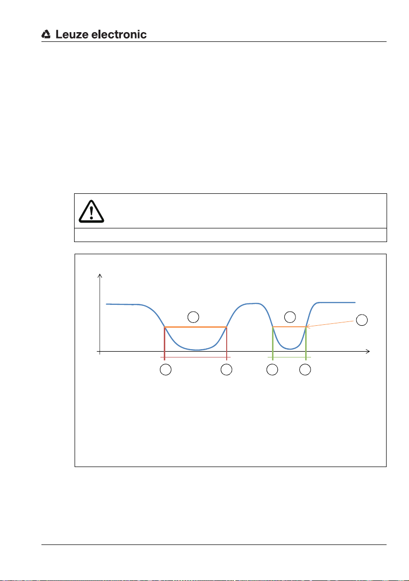
AB
CD
x Edge position
y Amplitude reception signal
A Left edge of guide trace
B Right edge of guide trace
C Trace too wide according to active "Trace width" filter
D Trace OK
E Teac h th r esh old
E
AB
If the sensor is to output only traces which correspond to a certain trace width, the "Trace
width" filter can be activated.
The filter value can be set to the trace by means of a teach or manually by entering the
values in the corresponding indices.
Traces filtered out by the filter can be read out via the TraceInvalidSubPixel index (UART
index 213
During the trace width teach, the TraceTeachThr parameter is calculated. The position of
the left and right edge is determined for the amplitude of this threshold. If a trace is detected
which does not allow the trace width to be calculated with the threshold determined during
the teach, then the threshold is adapted for this particular trace. The taught threshold is used
as soon as the amplitude of the found background-trace combination permits this.
The trace width depends on the value of this threshold.
and CAN index 2027h [1h]…[Ch]).
d
CAUTION
y
Configuring the sensor – Overview of functions
Figure 7.5: Application of the "Trace width" filter using a dark trace as an example
Leuze electronic OGS 600 39
x0 3000
TNT 35/7-24V
Page 42

Configuring the sensor – Overview of functions
7.5.1 Teaching the trace width
The TraceWidthTol parameter (UART Index 102d and CAN Index 2010h [3h]) is used during
the teach in order to define the upper and lower limit for the trace width on the basis of the
currently measured trace width.
Calculation of the values in the sensor:
Trace width = │Position of left edge - Position of right edge│
Trace Wi dt hM ax = Trace width + Tr ac eW id th Tol
Trace Wi dt hM in = Trace width - Trac eW id th Tol
7.5.2 Manual configuration of the trace width
If the trace width is to be configured manually, the values can be written directly to the
parameters TraceWidthMax (UART index 100
WidthMin (UART index 101
Remember to apply the factor 10 during conversion: 10
CAUTION
If a trace width teach is performed, manually configured trace width values are overwritten.
and CAN index 2010h [2h]).
d
7.5.3 Process data information for the "Trace width" filter
If the number of detected traces which, owing to the "Trace width" filter, are not output in the
process data is greater or equal to one, then bit 3 is set in process data byte 2 Status PD.
and CAN index 2010h [1h]) and Trace-
d
corresponds to 1mm.
d
Leuze electronic OGS 600 40
TNT 35/7-24V
Page 43

Configuring the sensor – Overview of functions
7.5.4 Index overview for the "Trace width" filter
Bit counting method: bit0 … bit15
Name Index
Activation of
"Trace width" filter
Deactivation of
"Trace width" filter
Trace width teach 2
TraceWidthMax 100
TraceWidthMin 101d 2010h [2h] 2 RW (290d) Minimum trace width
TraceWidthTol 102
TraceTeachThr 112
Status 200
UserMode 75
Index
UART
[subindex]
CANopen
2d 2000h [0h] 2 W 229d System command
2000h [0h] 2 W 230d System command
2
d
2000h [0h] 2 W 194d System command
d
2010h [1h] 2 RW (490d) Maximum trace width
d
2010h [3h] 2 RW (100d) Trace width tolerance
d
2010h [Dh] 2 R Determined during teach
d
2020h [1h] 2 R Bit no. 5 If the number of filtered-out traces is
d
2002h [0h] 2 R Bi t no. 2 If the bit is set, then the "Trace width"
d
Index
length
[byte]
Access Data / (default
value)
Info
For manual configuration
or result from teach
Value: [ mm * 10 ]
For manual configuration
or result from teach
Value: [ mm * 10 ]
Only required for teach
Value: [ mm * 10 ]
≥ 1, the bit is set.
See also process data status byte, bit
no. 3 (Chapter 8.1.4.1)
filter is active.
Table 7.5: Index accesses for the "Trace width" filter
Leuze electronic OGS 600 41
TNT 35/7-24V
Page 44

Configuring the sensor – Overview of functions
AB
C
D
x Edge position
y Reception signal amplitude
A Left edge of guide trace
B Right edge of guide trace
C Trace width
D Amplitude of background
E Amplitude of guide trace
F Contrast
G Warning threshold for minimum contrast
H Minimum contrast (TraceContrastMin)
J Verification of minimum contrast.
The second, right trace is not output because the minimum contrast is not fulfilled.
G
E
F
H
J
7.6 "Minimum contrast" filter
The filter for the minimum contrast queries whether the brightness of the background and
the brightness of the trace have a minimum difference.
This minimum difference can be taught based on a reference trace, or the value can be set
manually.
y
0 3000
Figure 7.6: Application of the "Minimum contrast" filter using a dark trace as an example
7.6.1 Teaching the minimum contrast
Leuze electronic OGS 600 42
The value of the TraceContrastTol parameter (UART index 105d and CAN index 2010h [6h])
is used for calculating a minimum threshold for the contrast using the contrast value
measured during the teach. The value appears as a percentage [%] in the index.
Calculation in the sensor:
Contrast = │Amplitude_environment - Amplitude_trace│
TraceContrastMin = Contrast - ( Contrast * TraceContrastTol /100 )
x
TNT 35/7-24V
Page 45

Configuring the sensor – Overview of functions
7.6.2 Manual configuration of the minimum contrast
If the minimum contrast is to be configured manually, it can be written directly to the TraceContrastMin parameter (UART index 103
CAUTION
If a minimum contrast teach is performed, a manually configured minimum contrast value
is overwritten.
7.6.3 Warning for minimum contrast
The warning threshold corresponds to a percentage deviation from the minimum contrast
TraceContrastMin (UART index 103
the minimum contrast is calculated using the TraceContrastWarning factor (UART
index 104
Calculation:
and CAN Index 2010h [5h]). There is no index for calling up this value directly.
d
TraceContrastWarning_threshold = TraceContrastMin + ( TraceContrastMin * TraceContrastWarning )
7.6.4 Process data information for the "Minimum contrast" filter
In the status byte of the process data, there are two bits for information relating to the
minimum contrast:
•Bit1: Minimum contrast warning
•Bit4: Minimum contrast error
Bit 1 Minimum contrast warning is set if the number of detected traces for which the
minimum contrast is less then the warning threshold, is greater than or equal to one.
Bit 4 Minimum contrast error is set if the number of detected traces for which the contrast is
less than TraceContrastMin, is greater than or equal to one.
and CAN index 2010h [4h]) as a value in [LSB].
d
and CAN index 2010h [4h]). The warning threshold for
d
Leuze electronic OGS 600 43
TNT 35/7-24V
Page 46

Configuring the sensor – Overview of functions
7.6.5 Index overview for the "Minimum contrast" filter
Bit counting method: bit0 … bit15
Name Index
Activate filter 2d 2000h [0h] 2 W 231d System command
Deactivate filter 2
Teaching the minimum
contrast
TraceContrastMin 103
TraceContrastWarning 104
TraceContrastTol 105
Status 200
Status 200
UserMode 75
Index
UART
[subindex]
CANopen
2000h [0h] 2 W 232d System command
d
2
2000h [0h] 2 W 195d System command
d
2010h [4h] 2 RW (5500d) Result from teach or manual entr y, unit:
d
2010h [5h]2 RW (20d) Factor for calculation of warning thresh-
d
2010h [6h]2 RW (30d) Tolerance is used in teach event, unit:
d
2020h [1h] 2 R Bit no. 6 1 = Minimum contrast error
d
2020h [1h] 2 R Bit no. 3 1 = Minimum contrast warning
d
2002h [0h] 2 R Bi t no. 3 If bit = 1, then "Minimum contrast" filter
d
Index
length
[byte]
Access Data / (default
value)
Info
[LSB]
old, unit [%]
[%]
See also process data status byte, bit
no. 4 (Chapter 8.1.4.1)
See also process data status byte, bit
no. 1 (Chapter 8.1.4.1)
is active.
Table 7.6: Index accesses for the "Minimum contrast" filter
Leuze electronic OGS 600 44
TNT 35/7-24V
Page 47

7.7 "Trace amplitude" filter
AB
C
D
x Edge position
y Reception signal amplitude
A Left edge of guide trace
B Right edge of guide trace
C Trace width
D Amplitude of background
E Amplitude of guide trace
F Invalid trace amplitudes (red area)
G TraceAmplitudeMin value
H TraceAmplitudeWarning value
G
E
F
H
The filter is based on the assumption that the guide trace tape processed in a system is the
same throughout. If this is the case, then the guide trace tape is a known constant. As a
result, all other markings with a different amplitude can be filtered out.
It is therefore recommended to select a guide trace tape which is as light as possible (white)
or as dark as possible (black) so that there are no markings which are darker or lighter than
the optical trace.
The filter for trace amplitude is the limit value TraceAmplitudeMin (UART index 106
CAN index 2010
trace signal is greater than the limit value. There is a warning threshold which is set using
the TraceAmplitudeWarning parameter (UART index 107
y
[7h]) which marks as incorrect all traces for which the amplitude of the
h
Configuring the sensor – Overview of functions
and
d
and CAN index 2010h [8h]).
d
0 3000
Figure 7.7: Application of the "Trace amplitude" filter using a dark trace as an example
Leuze electronic OGS 600 45
x
TNT 35/7-24V
Page 48

Configuring the sensor – Overview of functions
7.7.1 Teaching the trace amplitude
The TraceAmplitudeTol value (UART index 108d and CAN index 2010h [9h]) is used for
setting the TraceAmplitudeMin limit value (UART index 106
the "Trace amplitude" filter during the teach.
Calculation of dark guide trace:
TraceAmplitudeMin = Amplitude_trace [LSB] + Trace Amp l itu deTo l [LSB]
Calculation of light guide trace:
TraceAmplitudeMin = Amplitude_trace [LSB] - TraceAmplitudeTol [LSB]
7.7.2 Manual configuration of the trace amplitude
If the trace amplitude limit value is to be configured manually, it can be written directly to the
TraceAmplitudeMin parameter (UART index 106
[LSB].
CAUTION
If a trace amplitude teach is performed, a manually configured trace amplitude limit value
is overwritten.
7.7.3 Warning for trace amplitude
The warning threshold corresponds to a percentage deviation from the trace amplitude limit
value TraceAmplitudeMin (UART index 106
The warning threshold for the trace amplitude is calculated using the
TraceAmplitudeWarning factor (UART index 107
index for calling up the calculated value directly.
Calculation of dark guide trace:
TraceAmplitudeWarning_threshold = TraceAmplitudeMin [LSB] - ( TraceAmplitudeMin [LSB] * Tra c eA mpl itu deW ar nin g )
and CAN index 2010h [7h]) as a value in
d
and CAN index 2010h [7h]).
d
and CAN index 2010h [8h]). There is no
d
and CAN index 2010h [7h]) for
d
TNT 35/7-24V
Calculation of light guide trace:
TraceAmplitudeWarning_threshold = TraceAmplitudeMin [LSB] + ( TraceAmplitudeMin [LSB] * T raceAmplitudeWarning )
Leuze electronic OGS 600 46
Page 49

Configuring the sensor – Overview of functions
7.7.4 Process data information for the "Trace amplitude" filter
In the status byte of the process data, there are two bits for information relating to the trace
amplitude:
•Bit2: Trace amplitude warning
•Bit5: Trace amplitude error
The Trace amplitude warning bit is set if the number of detected traces for which the trace
amplitude is greater (dark guide trace) or less (light guide trace) than the warning threshold,
is greater than or equal to one.
The Trace amplitude error bit is set if the number of detected traces for which the contrast
is greater (dark guide trace) or less (light guide trace) than TraceAmplitudeMin, is greater
than or equal to one.
7.7.5 Index overview for the "Trace amplitude" filter
Bit counting method: bit0 … bit15
Name Index
Activate filter 2
Deactivate filter 2
Teaching the minimum
contrast
TraceAmplitudeMin 106
TraceAmplitudeWarning 107
TraceAmplitudeTol 108
Status 200
Status 200
UserMode 75
Index
UART
[subindex]
CANopen
2000h [0h] 2 W 233d System command
d
2000h [0h] 2 W 234d System command
d
2000h [0h] 2 W 196d System command
2
d
2010h [7h] 2 RW (2500d) Result from teach or manual change,
d
2010h [8h]2 RW (20d) Factor for calculation of warning thresh-
d
2010h [9h] 2 RW (1000d) During teach:
d
2020h [1h] 2 R Bit no. 7 1 = Trace amplitude error
d
2020h [1h] 2 R Bit no. 4 1 = Trace amplitude warning
d
2002h [0h] 2 R Bit no. 4 If bit = 1, then "Trace amplitude" filter
d
Index
length
[byte]
Access Data / (default
value)
Table 7.7: Index accesses for the "Trace amplitude" filter
Info
unit [LSB]
old, unit [%]
Tolerance for calculation of minimum
threshold, unit [LSB]
See also process data status byte, bit
no. 5 (Chapter 8.1.4.1)
See also process data status byte, bit
no. 2 (Chapter 8.1.4.1)
is active
TNT 35/7-24V
Leuze electronic OGS 600 47
Page 50

Configuring the sensor – Overview of functions
7.8 Index overview – More data on correct and incorrect traces
It is also possible to access the detected and filtered traces without accessing the process
data. In doing so, additional information on the traces can be retrieved:
• With valid traces, the warning (if available) is shown in the TraceValidStatus index
(UART index 210
• With filtered-out traces, the error why the trace was filtered out is shown in the
TraceInvalidStatus index (UART index 215
• The amplitudes which are used for calculating the filters can be read in the
TraceValidAmp index (UART index 209
• The data for filtered-out traces can be read in the TraceInvalidAmp index
(UART index 214
The data is always sorted by edge/trace in ascending order.
Direct access to all data of valid traces
and CAN index 2025h [01…06]) for each trace.
d
and CAN index 2029h [01…06]).
d
and CAN index 2023h [01…12]).
d
and CAN index 2028h [01…12]).
d
Name Index
TraceValidSubPixel 207d 2022h
TraceValidAmp 208
TraceValidStatus 210
UART
d
d
Index
[subindex]
CANopen
[1
]…[Ch]
h
2023h
[1
]…[Ch]
h
2025h
[1
]…[6h]
h
Index
length
[byte]
24 R [ LeftEdge1 LowByte,
24 R [ Environment1 LowByte,
12 R [ Trace1,
Access Data Info
LeftEdge1 HighByte,
RightEdge1 LowByte,
RightEdge1 HighByte,
LeftEdge2 LowByte,
LeftEdge2 HighByte,
RightEdge2 LowByte,
RightEdge2 HighByte,
…]
Environment1 HighByte,
Trace1 LowByte,
Trace1 HighByte,
Environment2 LowByte,
Environment2 HighByte,
Trace2 LowByte,
Trace2 HighByte,
…]
Trace2,
Trace3,
…]
Table 7.8: Index overview: direct access to all data of valid traces
Contains the edge positions of
the valid traces:
• 16 bit for each edge
• Divided into LowByte and
HighByte
• Only traces are displayed
• A trace always consists of
two consecutive edges
Contains the amplitude of the
environment and of the trace:
• 16 bit amplitude value
• Divided into LowByte and
HighByte
• Sorted in ascending order
consistent with the traces
in index 207 and 2022
The warning is shown for each
trace.
Data:
1
: contrast warning
h
2
: trace amplitude warning
h
h
TNT 35/7-24V
Leuze electronic OGS 600 48
Page 51

Configuring the sensor – Overview of functions
Direct access to all data of invalid traces
Name Index
TraceInvalidSubPixel 213d 2027h
TraceInvalidAmp 214
TraceInvalidStatus 215
UART
d
d
Index
[subindex]
CANopen
[1
]…[Ch]
h
2028h
[1
]…[Ch]
h
2029h
[1
]…[6h]
h
Index
length
[byte]
24 R [ LeftEdge1 LowByte,
24 R [ Environment1 LowByte,
12 R [ Trace1,
Access Data Info
LeftEdge1 HighByte,
RightEdge1 LowByte,
RightEdge1 HighByte,
LeftEdge2 LowByte,
LeftEdge2 HighByte,
RightEdge2 LowByte,
RightEdge2 HighByte,
…]
Environment1 HighByte,
Trace1 LowByte,
Trace1 HighByte,
Environment2 LowByte,
Environment2 HighByte,
Trace2 LowByte,
Trace2 HighByte,
…]
Trace2,
Trace3,
…]
Table 7.9: Index overview: direct access to all data of invalid traces
Contains the edge positions of
the valid traces:
• 16 bit for each edge
• Divided into LowByte and
HighByte
• Only traces are displayed
• A trace always consists of
two consecutive edges
Contains the amplitude of the
environment and of the trace:
• 16 bit amplitude value
• Divided into LowByte and
HighByte
The error is shown for each
trace.
Data:
1
: contrast error
h
2
: trace amplitude error
h
4
: trace width error
h
Leuze electronic OGS 600 49
TNT 35/7-24V
Page 52

8 Commissioning
8.1 Communication protocol for serial interfaces (UART)
The following default settings apply for the RS232, RS485 and RS422 serial interfaces.
Baud rate [bit/s] 115200
Parity Odd
Data bits 8
Stop bits 1
Node number 1
Minimum response time Can be set for RS485; see the parameter RS485Delay
(index 149).
Table 8.1: Factory settings for the communication protocol of serial interfaces
8.1.1 RS485/RS422 node address
The node address is set via index 70 UART Node No (see chapter 8.2 "Object directory for
serial interfaces (UART)"). It is recommended to change the default address if, in the case
of RS485/RS422, multiple devices are connected to the bus.
If a device is reset to the factory settings, the default address (1) is restored. This avoids an
address collision.
Commissioning
8.1.2 Error handling
The following communication errors are intercepted and/or returned:
• Too few characters:
after timeout (1.6ms), the receive buffer is cleared -> no error telegram.
• Too many characters: cannot be detected. The valid characters are processed (CRC
check) and the remaining characters are discarded.
• Incorrect CRC: error telegram 8112
• Error during reception (parity error, ...): error telegram 8113
• Incorrect identifier: error telegram 8111
• Maximum time taken for the sensor to respond to a query: 1.2 ms
Leuze electronic OGS 600 50
h
h
h
TNT 35/7-24V
Page 53

8.1.3 Index access
Basic structure of the protocol:
Byte 0 Byte 1 Byte 2 Byte 3 Byte 4 Byte 5 Byte 6 Byte 7 Byte 8 Byte 9
Node no./
identifier
Byte 0: Always contains the device address (node number). This can be changed. The
Byte 1: Contains the number of data bytes.
Byte 2: Contains the lowbyte of the index to be read or written.
Byte 3: Contains the highbyte of the index to be read or written.
Byte 4: Contains the sub-index of the index to be read or written.
Byte 5…n: Data which is written or read.
Byte n+1: CRC is calculated from byte 0 to byte n. Process: XOR with start value 0.
In the case of access to an index, the identifier indicates what is to be done. There are three
different query identifiers. The sensor returns a corresponding identifier in response to the
query.
If an error was detected in the data transfer, the identifier nF
chapter 8.1.5 "Error codes") are returned as the response.
Length Index low-
identifier indicates what is to be done: read, write, request PD.
Bit 3…0: Identifier
Bit 7…4: Node no. n
The length is counted from byte 5 to byte n-1.
byte
Index highbyte
Commissioning
Sub-index Data 0 Data 1 Data 2 Data 3 CRC
and an error code (see
h
Identifiers
Type Identifier for
Read n1
Write n2
Process data n3
Error nF
n = node number
query
n4h Response from sensor:
h
n8h Write to sensor:
h
nCh
h
Identifier for
sensor response
h
Function of byte 1 "Length"
Length indicates how much data is sent by the sensor: from byte
5 without CRC byte
Length indicates how much data is sent to the sensor; if the data
length exceeds the object length, an error is returned.
Table 8.2: Identifiers for working with indices
Leuze electronic OGS 600 51
TNT 35/7-24V
Page 54

Example:
Type Byte 0 Byte 1 Byte 2 Byte 3 Byte 4 Byte 5 Byte n + 1
Query Read 11
Response Read 14
Node no./
identifier
Length Index
0C8
h
Quantity
h
Data bytes
lowbyte
C8h 00h 0Data n CRC
Table 8.3: Example of a query to read byte
Node no.: 1
Index: 200 (LowByte: C8
, HighByte: 00h)
h
Commissioning
Index
highbyte
00h 0 CRC
h
Subindex
Data n CRC
Leuze electronic OGS 600 52
TNT 35/7-24V
Page 55

8.1.4 Process data
There are different types of process data. They are used for calling up various information.
In addition, a setting for the "Switch" function can be changed in the sensor by sending the
process data byte query.
Process data query
The structure of the query from byte 0 to byte 4 is the same for all process data types.
Type Byte 0 Byte 1 Byte 2 Byte 3 Byte 4
Query PD n3
Byte 0: Always contains the device address (node number). This can be changed. The
identifier indicates what is to be done: request PD.
Bit 3…0: Identifier
Bit 7…4: Node no. n
Byte 1: Contains the process data type: 1 or 4.
Byte 2: PD-In1:
Data can be written to the sensor in order to change settings (example:
"Switch" function). The changed setting is applied for the first time with the next
PD query.
Byte 3: PD-In2:
Reserve.
Byte 4: CRC is calculated from byte 0 to byte 3. Process: XOR with start value 0.
Process data response
Type Byte 0 Byte 1 Byte 2 Byte 3 Byte n Byte n + 1
Response PD nC
Table 8.4: Request for process data:
Byte 0: Device number as well as identifier (in this case nC
Byte 1: Number of sent user data bytes, varies depending on the PD type.
Byte 2: Status PD contains the eight most important pieces of information about the
detected traces.
Byte 3: Contrast is a value reduced to 8 bits and indicates the contrast of the trace.
Byte 4: Data of the detected traces
Byte n+1: The last byte is the CRC byte.
PD type PD-In1 PD-In2 CRC
h
Length
h
User data
PD status Contrast Data CRC
Commissioning
)
h
TNT 35/7-24V
Leuze electronic OGS 600 53
Page 56

8.1.4.1 Status byte in the process data
The process data status byte is composed of 8 bits which convey a state for each filter and
when the warning threshold for the filter is reached. It is output if a global error is present or
when no trace at all has been detected.
The state is always active if the corresponding bit is set.
Bit 0: General error –> Reading out of index 201 Error
Bit 1: Minimum contrast warning see chapter 7.6 ""Minimum contrast" filter"
Bit 2: Trace amplitude warning see chapter 7.7 ""Trace amplitude" filter"
Bit 3: Trace width error see chapter 7.5 ""Trace width" filter"
Bit 4: Minimum contrast error see chapter 7.6 ""Minimum contrast" filter"
Bit 5: Trace amplitude error see chapter 7.7 ""Trace amplitude" filter"
Bit 6: Switch active see chapter 7.4 "Switch"
Bit 7: No trace detected –> Check guide trace/background
NOTE
Data for traces (edge positions, contrast) which are declared as invalid by a filter is never
output via the process data.
Commissioning
Leuze electronic OGS 600 54
TNT 35/7-24V
Page 57

8.1.4.2 Contrast byte in the process data
The difference between the amount of light reflected by the ground next to the guide trace
and the amount of light reflected by the guide trace itself is an important measure for assessment of the optical state of the trace.
This value is defined by the following calculation (see also Figure 7.6):
Contrast = Amplitude_of_environment - Amplitude_of_trace
This value is known during commissioning of the system. By moving over the guide trace
when it is in its new condition, it is possible to determine the poorest contrast of the system.
The state of the guide trace can be checked continuously during operation.
NOTE
Contrast output values in the process data
If one valid trace is detected, the contrast of this trace is output.
If more than one valid trace is detected, the contrast of the trace with the poorest contrast,
e.g. at a switch, is output.
Conversion
To be able to compare the contrast value in the process data with the values in the indices
of the "Minimum contrast" or "Trace amplitude" filters, the value from the process data must
be multiplied by 100.
Contrast = Hex2Dec(byte 3) * 100
Commissioning
Leuze electronic OGS 600 55
TNT 35/7-24V
Page 58

8.1.4.3 Type 1 process data
A
B
C
D
A Guide trace; here dark trace on light background
B Left edge of guide trace
C Right edge of guide trace
D Width of the sensor's measurement field
"Trace width" filter = OFF
Type 1 process data outputs the position of a left and a right edge.
If the sensor finds one trace, the left and the right edge of this trace is output. If the sensor
finds two traces, then the outermost left edge and the outermost right edge of the detected
traces are output.
If filters such as trace width, minimum contrast or trace amplitude are active, they are effective for PD type 1.
Commissioning
Figure 8.1: Output of the left edge and right edge with PD type 1.
The "Trace width" filter is OFF in Figure 8.1 because the wide trace would otherwise not be
detected at the midpoint of the switch.
With active "Trace width" filter, the "Switch" function can be used as an alternative (see
chapter 7.4 "Switch"). In this case, additional information is sent in byte 2 (data) when the
process data is requested.
Leuze electronic OGS 600 56
TNT 35/7-24V
Page 59

Type 1 process data query
Type Byte 0 Byte 1 Byte 2 Byte 3 Byte 4
Query PD 13
Node no./
identifier
PD type PD-In1 PD-In2 CRC
1
h
0
h
0
h
CRC
h
Table 8.5: Type 1 process data query
Type 1 process data response
Byte 0 Byte 1 Byte 2 Byte 3 Byte 4 Byte 5 Byte 6 Byte 7 Byte 8
Response 1C
Node no./
identifier
User data
length
04h 0h 78h B0h 04h 14h 05h
h
PD status Contrast Left
edge
lowbyte
Table 8.6: Example response for type 1 process data
Contrast = 120 * 100 = 12000 LSB
Left edge of the trace = 1200 / 10 = 120.0 mm
Right edge of the trace = 1300 / 10 = 130.0 mm
Left
edge
highbyte
Commissioning
Right
edge
lowbyte
Right
edge
highbyte
CRC
Leuze electronic OGS 600 57
TNT 35/7-24V
Page 60
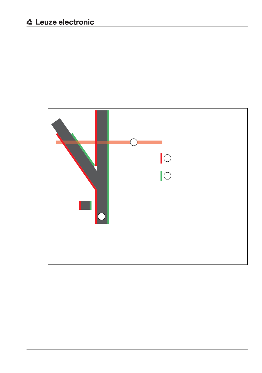
8.1.4.4 Type 4 process data
A
B
C
D
A Guide trace; here dark trace on light background
B Left edge of guide trace
C Right edge of guide trace
D Width of the sensor's measurement field
"Trace width" filter = OFF
Type 4 process data outputs the positions of up to six detected traces.
If the sensor finds one trace, the left and the right edge of this trace is output. If the sensors
finds two or more traces, the left and right edges of all valid traces are output. The traces in
the process data are arranged in ascending order according to the position at which they
were found. The trace with the smallest position is always output first and is therefore always
trace no. 1. All subsequent traces are arranged in ascending order according to their position and the trace number is incremented.
If filters such as trace width, minimum contrast or trace amplitude are active, they are effective for PD type 4.
Commissioning
Figure 8.2: Output of the left edge and right edge with PD type 1.
The "Trace width" filter is OFF in Figure 8.2, recognizable by the fact that the wide trace is
detected at the midpoint of the switch. With active "Trace width" filter, the "Switch" function
can be used as an alternative (see chapter 7.4 "Switch"). In this case, additional information
is sent in byte 2 (data) when the process data is requested.
Leuze electronic OGS 600 58
TNT 35/7-24V
Page 61

Commissioning
Type 4 process data query
Type Byte 0 Byte 1 Byte 2 Byte 3 Byte 4
Node no./
identifier
Query PD 13
Table 8.7: Type 4 process data query
Type 4 process data response
Byte 0 Byte 1 Byte 2 Byte 3 Byte 4 Byte 5 Byte 6 Byte 7
Node no./
identifier
Response 1C
Byte 8 Byte 9 Byte 10 Byte 11 Byte 12
Left
edge
lowbyte
DC
Left
edge
highbyte
05h 40h 6h
h
User data
length
08h 0h 78h B0h 4
h
Trace 2
Right
edge
lowbyte
Table 8.8: Example response for type 4 process data with 2 traces
Contrast = 120 * 100 = 12000 LSB
Left edge of trace 1 = 1200 / 10 = 120.0 mm
Right edge of trace 1 = 1300 / 10 = 130.0 mm
Left edge of trace 2 = 1500 / 10 = 150.0 mm
Right edge of trace 2 = 1600 / 10 = 160.0 mm
From the number of user data bytes, it is possible to calculate how many traces have been
found:
• per edge: 2 bytes
• per trace: 2 edges
=> This results in 4 bytes of user data per trace.
PD type PD-In1 PD-In2 CRC
04h 0
h
PD status Contrast Left
Right
edge
highbyte
0
h
CRC
CRC
h
edge
lowbyte
Trace 1
Left
edge
highbyte
Right
edge
lowbyte
14h 05h
h
Right
edge
highbyte
TNT 35/7-24V
Leuze electronic OGS 600 59
Page 62

8.1.5 Error codes
Error code Error description Reaction
8011
8012
8020
8023
8030
8031
8032
8033
8034
8035
8082
8111
8112
8113
Table 8.9: Error codes for data transfer
Index is not available / released Check index
h
Sub-index is not available / released Sub-index must always be 0
h
Service temporarily unavailable
h
(memory function for flash is still assigned)
Access denied (index write only) Check index (see Table 8.11)
h
Value is outside permissible value range Check value which is to be written to index (see Table 8.11)
h
Maximum is above permissible value range Check value which is to be written to index (see Table 8.11)
h
Minimum is below permissibl e value range Check value which is to be written to index (see Table 8.11)
h
Length of object is above maximum Check data length (see Table 8.11)
h
Length of object is below minimum Check data length (see Table 8.11)
h
Unknown command in index 2 Check value Command not present
h
Internal error -> abort Repeat several times, otherwise sensor defective
h
UART: incorrect identifier Check identifier (for valid identifiers, see Table 8.2)
h
UART: incorrect CRC Check CRC calculation
h
Receive error (parity, …) Repeat several times, otherwise sensor defective
h
Commissioning
Repeat several times, otherwise sensor defective
(see Table 8.12)
Leuze electronic OGS 600 60
TNT 35/7-24V
Page 63

Commissioning
8.2 Object directory for serial interfaces (UART)
Data types: Access:
string Convert bytes into ASCII characters in incoming sequence RW Read Write
uint16 Arrangement: [ LowByte, HighByte ] RO Read Only
uint32 Arrangement: [ LowByte, LowerByte, HigherByte, HighByte ] WO Write Only
array_uint16 Arrangement: [ LowByte1, HighByte1, LowByte2, HighByte2, … ]
int16 Arrangement: [ LowByte, HighByte ]
Table 8.10: Object directory – data types and access
UART
UART
Index
2
d
16
17
18
19
20
21
22
23
70
71
72
73
75
76
77
Name Description Access Comments Default Value
Sub
Index
0d System Command System command WO See Table 8.12 1
0d Vendor Name Device manufacturer RO Leuze ele ctronic GmbH + Co. KG 32 string
d
0d Vendor Text M anufacturer text RO Leuze electronic - the sensor people 38 string
d
0d Product Name Product designation RO <Product Name> 32 string
d
0d Product ID Part no. of the device RO <Part number> 16 string
d
0d Product Text Product text RO <Product text> 32 string
d
0d Serial Number Device serial number RO <Serial number> 16 string
d
0d Hardware Revision Version of the device hardware RO <Hardware revision>, e.g. 000B 8 string
d
0d Firmware Revision Version of the device firmware RO <Firmware revision>, e.g. 1.1 8 string
d
0d UART Node No UART node address RW RS485/RS422 device address 1 0…15 2 uint16
d
0d UART Baud rate UART baud rate RW For future use 2 uint16
d
0d Can Node No CAN node address RW CANopen device address 10 0…127 2 uint16
d
0d Can Baud rate CAN baud rate RW 0 = 1 Mbit/s
d
0d UserMode UserMode RW Bit 0: 1 = dark trace; 0 = lig ht trace
d
0d Qproperty Output behavior with no mea-
d
0d Q1UpperSwitchingPoint Upper switching point for
d
surement value
switching output SW_IO (pin 4)
1 = not used
2 = 500 kbit/s
3 = 250 kbit/s
4 = 125 kbit/s
5 = 100 kbit/s
6 = 50 kbit/s
7 = 20 kbit/s
8 = 10 kbit/s
Bit 1: angle compensat ion active
Bit 2: filter: trace width
Bit 3: filter: contrast
Bit 4: filter: amplitude
Bit 5: teach trace width
Bit 6: teach contrast
Bit 7: teach amplitude
Bit 8: retro-reflective trace
RW 0d: off,
: on,
1
d
2
: unchanged,
d
applies to both outputs
RW With trace monitoring:
range: 0…3000 (long device version),
range: 0…1500 (short device version),
unit: 0.1mm
With contrast monitoring:
range: 0…21200, unit: [LSB]
00…82uint16
Bit 0= 1 0…
00…22uint16
00…
range
65535
65535
Length
[byte]
2uint16
2uint16
Data
type
TNT 35/7-24V
Leuze electronic OGS 600 61
Page 64

UART
UART
Index
78d 0d Q1LowerSwitchingPoint Lower switching point for
79
80
81
82
83
84
85
86
87
88
100
101
Name Description Access Comments Default Value
Sub
Index
switching output SW_IO (pin 4)
0d Q1LightDark Switching behavior
d
0d Q1SwitchPtMode Switching point mode for
d
0d Q1Hysteresis Switching hysteresis for
d
0d Q2UpperSwitchingPoint Upper switching point for
d
0d Q2LowerSwitchingPoint Lower switching point for
d
0d Q2LightDark Switching behavior
d
0d Q2SwitchPtMode Switching point mode for
d
0d Q2Hysteresis Switching hysteresis for
d
0d Q1UserConfig Configuration of switching out-
d
0d Q2UserConfig Configuration of IO switching
d
TraceWidthMax Maximum trace width RW For manual configuration (changed by means
d 0d
TraceWidthMin Minimum trace width RW For manual configuration (changed by means
d 0d
Light/dark switching for
switching output SW_IO (pin 4)
switching output SW_IO (pin 4)
switching output SW_IO (pin 4)
switching output IO (pin 2)
IO switching output (pin 2)
Light/dark switching for
switching output IO (pin 2)
switching output IO (pin 2)
IO switching output (pin 2)
put SW_IO (pin 4)
output/switching input (pin 2)
RW With trace monitoring:
range: 0…3000 (long device version),
range: 0…1500 (short device version),
unit: 0.1mm
With contrast monitoring:
range: 0…21200, unit: [LSB]
RW 0d: Q = high outside switching points,
: Q = high inside switching points,
1
d
see Table 5.1
RW 0d: switching output deactivated
1
: trace monitoring
d
: contrast monitoring
2
d
RW With trace monitoring:
range: 0…3000 (long device version),
range: 0…1500 (short device version),
unit: 0.1mm
With contrast monitoring:
range: 0…21200, unit: [LSB]
RW With trace monitoring:
range: 0…3000 (long device version),
range: 0…1500 (short device version),
unit: 0.1mm
With contrast monitoring:
range: 0…21200, unit: [LSB]
RW With trace monitoring:
range: 0…3000 (long device version),
range: 0…1500 (short device version),
unit: 0.1mm
With contrast monitoring:
range: 0…21200, unit: [LSB]
RW 0d: Q = high outside switching points,
1
: Q = high inside switching points,
d
see Table 5.1
RW 0d: switching output deactivated
1
: trace monitoring
d
2
: contrast monitoring
d
RW With trace monitoring:
range: 0…3000 (long device version),
range: 0…1500 (short device version),
unit: 0.1mm
With contrast monitoring:
range: 0…21200, unit: [LSB]
RW 0d: not active
1
: Out_PP (push-pull)
d
2
: Out_NPN
d
: Out_PNP
3
d
RW 0h: not active
1
: Out_PP (push-pull)
h
2
: Out_NPN
h
: Out_PNP
3
h
104
: In_NPN deactivation input
h
105
: In_PNP deactivation input
h
304
: In_NPN activation input
h
: In_PNP activation input
305
h
of a trace width teach!),
unit: 0.1mm
of a trace width teach!),
unit: 0.1mm
Commissioning
Length
range
00…
65535
00…12uint16
00…22uint16
20 0…
65535
00…
65535
00…
65535
00…12uint16
00…22uint16
20 0…
65535
00…32uint16
00…
65535
490 0…
65535
290 0…
65535
Data
[byte]
type
2uint16
2uint16
2uint16
2uint16
2uint16
2uint16
2uint16
2uint16
TNT 35/7-24V
Leuze electronic OGS 600 62
Page 65

Commissioning
UART
UART
Index
102d 0d TraceWidthTol Trace width tolerance RW Only required for teach,
103
104
105
106
107
108
109
110
111
112
149
151
170
200
Name Description Access Comments Default Value
Sub
Index
unit: 0.1mm.
TraceContrastMin Minimum contrast R W Unit: [LSB] 5500 0…
d 0d
TraceContrastWarning Contrast warning threshold in % RW Unit: % 20 1…100 2 uint16
d 0d
TraceContrastTol Contra st tolerance RW Only required f or teach,
d 0d
Tra ceA mp lit ud eMi n Minimum amplitude RW Unit: [LSB] 2500 0…
d 0d
TraceAmplitudeWarning Amplitude warning threshold in % RW Unit: % 20 1…100 2 u int16
d 0d
Tra ceA mp lit ud eTol Ampl itude tolerance for teach RW Only required for teach,
d 0d
UserOffset Offs et for process data output RW PD output value = edge posit ion + offset 0
d 0d
SwitchTraceWidthFactor Trace width factor for switch
d 0d
SwitchDeviationThr Lower limit value for deviation
d 0d
TraceTeachThr Threshold which is taught RW Unit: [LSB] 7000 0…
d 0d
RS485Delay Delay before sending on RS485 RW Delay after reception of a telegram until
d 0d
UserState Status RO Bit 0 = 1: angle compensation OK
d 0d
SwitchNumber Switch function RW Activation of switch function for guide trace:
d 0d
Status Sensor state RO Bit 0: G lobal error
d 0d
function
with switch
unit: [LSB]
unit: [LSB]
RW Factor for widening trace with active switch
function (see index 170
unit: %
RW Used with active switch function,
unit: [LSB]
),
d
response is sent, unit: ms
Bit 1 = 1: trace teach OK
0
: Switch function not active
d
1
: Switch function active for guide trace 1
d
2
: Switch function active for guide trace 2
d
3
: Switch function active for guide trace 3
d
4
: Switch function active for guide trace 4
d
5
: Switch function active for guide trace 5
d
6
: Switch function active for guide trace 6
d
Bit 1: Compensation factors valid
Bit 2: Teach, compensation measurement
running
Bit 3: Trace contrast warning
Bit 4: Trace amplitude warning
Bit 5: Trace width error
Bit 6: Contrast error
Bit 7: Amplitude error
Bit 8: Supply voltage warning
Bit 9: Supply voltage error
Bit 10: Teaching error
Bit 11: Compensation error
Bit 12: Switch function active
Bit 13: Switch error: unknown trace
Bit 14: No trace detected
(number of edges < 2)
range
100 0…
65535
65535
30 0…
65535
65535
1000 0…
65535
-32768
… 32767
150 0…
65535
250 0…
65535
65535
10…
65535
00…
65535
00…62uint16
00…
65535
Length
Data
[byte]
type
2uint16
2uint16
2uint16
2uint16
2uint16
2int16
2uint16
2uint16
2uint16
2uint16
2uint16
2uint16
TNT 35/7-24V
Leuze electronic OGS 600 63
Page 66

Commissioning
UART
UART
Index
201d 0d Error Error description RO Bit 0: Teach: compensation values missing
202
205
206
207
208
209
210
211
212
213
214
215
216
220
221
Name Description Access Comments Default Value
Sub
Index
Bit 1: Teach: valid traces > 1; in valid traces;
switch active
Bit 2: Angle compensation:
compensation values missing
Bit 3: Angle compensation:
trace or edge detected
Bit 4: Hardwar e error:
Measurement interrupt error
Bit 5: Supply voltage warning
Bit 6: Supply voltage error
Bit 7: S witch: unknown trace
Pixel Single pixel measurement val-
d 0d
TraceValidNum Valid traces: number RO Value: 0 … 6 0 0…6 2 uint16
d 0d
TraceValidPixel Valid traces: pixels RO Contains raw edge data of valid traces 0 0…
d 0d
TraceValidSubPixel Valid traces: sub-pixels in mm RO Contains edge positions of valid trace s, unit:
d 0d
TraceValidAmp Valid traces: amplitude RO Contains amplitude of environment and of
d 0d
TraceValidThreshold Valid traces: threshold RO Contains threshold for edge position of every
d 0d
TraceValidStatus Valid traces: status RO Status is signaled for every valid trace:
d 0d
TraceInvalidNum Invalid traces: number RO Value: 0 … 6 0 0…6 2 uint16
d 0d
TraceInvalidPixel Invalid traces: pixels RO Contains raw edge data of invalid trac es 0 0…
d 0d
TraceInvalidSubPixel Invalid traces: subpixels in mm RO Contains edge positions of invalid traces, unit:
d 0d
TraceInvalidAmp Invalid traces: amplitude RO Contains amplitude of environment and of
d 0d
TraceInvalidStatus Invalid traces: status RO Status is signaled for every invalid trace:
d 0d
Contrast Minimum contrast of all traces RO Unit: [LSB] 0 0…
d 0d
SupplyVoltage Supply voltage RO Unit: [mV] 0 0…
d 0d
TempController Temperature controller RO Unit: [°C] 0 0…
d 0d
ues
RO Amplitude of 94 receiver signals,
unit: [LSB]
[mm] (see Chapter 7.8)
valid trace, unit: [LSB]
(see Chapter 7.8)
detected trace, unit: [ LSB]
Bit 0: Contrast warning
Bit 1: Trace amplitude warning
(see Chapter 7.8)
[mm] (see Chapter 7.8)
invalid trace, unit: [LSB]
(see Chapter 7.8)
Bit 0: Contrast error
Bit 1: Trace amplitude error
Bit 1: Trace width error
(see Chapter 7.8)
range
00…
32
2
0…
65535
65535
00…
65535
00…
65535
00…
65535
00…
65535
65535
00…
65535
00…
65535
00…
65535
65535
65535
65535
Table 8.11: Object directory for serial interfaces (UART)
Length
[byte]
4uint32
-1
188 array
24 array
24 array
24 array
24 array
12 array
24 array
24 array
24 array
12 array
2uint16
2uint16
2uint16
Data
type
_uint16
_uint16
_uint16
_uint16
_uint16
_uint16
_uint16
_uint16
_uint16
_uint16
TNT 35/7-24V
Leuze electronic OGS 600 64
Page 67

8.2.1 System commands for serial interfaces
Commands can be sent to the sensor via UART index 2 System Command.
Command Value Function / description
Dec. Hex
Device Reset 128
Factory reset 130
Activation 176
Deactivation 177
UART Boot 180
Teach: on trace mode 4 192
Teach: angle compensation measurement
Teach: on trace mode 1 194
Teach: on trace mode 2 195
Teach: on trace mode 3 196
Dark trace, light background 212
Light trace, dark background 213
Retro-reflective trace 214
Mode: "Trace width" filter ON 229
Mode: "Trace width" filter OFF 230
Mode: "Minimum contrast" filter ON 231
Mode: "Minimum contrast" filter OFF 232
Mode: "Trace amplitude" filter ON 233
Mode: "Trace amplitude" filter OFF 234
Delete angle compensation factors 240
Delete error 242
Table 8.12: System commands
80h Software reset
d
82h Reset to factory settings
d
B0h Sensor illumina tion ON
d
B1h Sensor illumina tion OFF
d
B4h Start UART boot loader
d
C0h Trace width, trace amplitude, minimum contrast
d
C1h Angle compensation teach
193
d
C2h Trace width only
d
C3h Minimum contrast only
d
C4h Trace amplitude only
d
D4h
d
D5h
d
D6h
d
E5h
d
E6h
d
E7h
d
E8h
d
E9h
d
EAh
d
F0h
d
F2h Delete error bits / error status
d
Commissioning
Leuze electronic OGS 600 65
TNT 35/7-24V
Page 68

8.3 CANopen communication protocol
8.3.1 General information on CANopen
8.3.1.1 Topology
The CAN bus is a serial 2-wire bus system to which all participants are connected in parallel
(i.e., using short stub cables). To avoid reflections, the bus must be terminated with a terminating resistor of 120ohm at each end of the trunk line. Terminating resistors are also
required for very short trunk line cable lengths.
8.3.1.2 Bus line (trunk line)
For CAN, the maximum cable length of the trunk line is predominantly limited by the signal
propagation time. The multi-master bus-access process (arbitration) requires that the
signals are present virtually simultaneously at all nodes/participants. Therefore, the cable
length of the trunk cable must be adapted to the baud rate.
Baud rate Bus length
1Mbit/s < 20 m
500kbit/s < 100 m
250kbit/s < 250 m
125kbit/s < 500 m
50kbit/s < 1000 m
20kbit/s < 2500 m
Table 8.13: CANopen bus length in relation to baud rate
Commissioning
8.3.1.3 Address assignment
NOTE
The participant-specific address for CANopen is also called the Node ID. Throughout this
handbook, the term "address" is used, which is identical to Node ID.
Each participant connected to CANopen is assigned its own address (Node ID). Up to 127
participants can be connected to one network. The addresses range from 1 to 127. The
address 0 is usually reserved for the CANopen master.
The node ID can be set in two ways:
• Via the object directory:
Index Sub-index Name Description Length [byte] Data type
2001
[1h] Can Node No CAN node address 2 uint16
h
•Via the Layer Setting Services function (LSS, see DS305 of CiA).
Leuze electronic OGS 600 66
TNT 35/7-24V
Page 69

8.3.1.4 Baud rate setting
The OGS 600 supports the following baud rates:
•1 Mbit/s
• 500 kBit/s
• 250 kBit/s
• 125 kBit/s
• 100 kBit/s
• 50 kBit/s
• 20 kBit/s
• 10 kBit/s
The OGS 600 is set to 1 Mbit/s by default.
The baud rate can be set in two ways:
• Via the object directory:
Index Sub-index Name Description Length [byte] Data type
2001
[2h ] Can Baud rate CAN baud rate:
h
•Via the Layer Setting Services function (LSS, see DS305 of CiA).
0 = 1 Mbit/s
1 = not used
2 = 500 kBit/s
3 = 250 kBit/s
4 = 125 kBit/s
5 = 100 kBit/s
6 = 50 kBit/s
7 = 20 kBit/s
8 = 10 kBit/s
9 = automatically by LSS
Commissioning
2uint16
Leuze electronic OGS 600 67
TNT 35/7-24V
Page 70

Commissioning
8.3.1.5 Communication mechanisms of the OGS 600 in the CANopen network
In a CANopen network, all participants have in principle equal privileges. Each participant
can initiate its data transmission independently. Here, the arbitration specified by the CIA
controls the access of the individual participants to the network.
Generally, each CAN participant listens in on the bus. The transmission process is started
only if the bus is not occupied by another CAN participant. When transmitting, the current
bus status is always compared to the own transmitted frame.
Arbitration process
If several participants start a transmission simultaneously, the arbitration process decides
which participant gains access to the network next. The individual participants are integrated
into a prioritization scheme via their bus address and the type of data to be transmitted
(index address of the data). Process data (PDOs) of a device are transmitted with a higher
priority than, for example, variable objects (SDOs) of a device.
The node address of the participant is another criterion for prioritizing a participant in the
network. The smaller the node address, the higher the priority of the participant in the
network.
Since every participant compares its own priority with that of the other participants at the
time of bus access, the participants with low priority discontinue their transmission activities
immediately. The participant with the highest priority obtains temporary access to the bus.
The arbitration process controls the access of all participants so that even participants with
a low priority have access to the bus.
8.3.1.6 Objects
All process data and parameters are stored as objects in the OGS 600. The object directory
(see Chapter 8.4) is the compilation of all process data and parameters of the OGS 600.
The object directory is structured in such a way that all objects are stored in the manufacturer-specific object area.
The objects are uniquely identified using an index addressing scheme. The structure of the
object directory, the assignment of the index numbers, as well as some mandatory entries
are specified in the CIA standard DS301 for CANopen.
TNT 35/7-24V
Leuze electronic OGS 600 68
Page 71

8.3.1.7 EDS file
For the user, the object directory of the OGS 600 is available as an EDS file (Electronic Data
Sheet).
Download the EDS file for the device at www.leuze.com.
NOTE
Download EDS file from the Internet!
Call up the Leuze home page: www.leuze.com.
Enter the type designation or part number of the device as the search term.
The EDS file can be found on the product page for the device under the Downloads
tab.
The EDS file contains all objects with index, sub-index, name, data type, default value,
minimum and maximum, and access privileges.
The EDS file describes the complete functionality of the OGS 600.
8.3.1.8 SDOs and PDOs
The data exchange in CANopen distinguishes between service data objects (SDOs),
which are used for transmitting the service data (parameters) from and to the object directory, and process data objects (PDOs), which are used to exchange the current process
states.
SDOs
By using SDOs, all entries of the object directory can be accessed. Within one SDO call, only
one object can be accessed at any one time. For this reason, a service data telegram must
have a protocol structure which describes the exact target address by means of index and
sub-index addressing. SDO telegrams place a part of the SDO addressing into the user data
area. Eventually, a user data area with a width of 4 bytes out of the possible 8 bytes of user
data remains for each SDO telegram.
The target address always responds to SDO transfers. In the following, the index and subindex address of the OGS 600 parameters and variables can be found in the individual
object descriptions.
PDOs
PDOs are objects (data, variables and parameters) from the object directory compiled
(mapped) by the device manufacturer. A maximum of 8 bytes of user data from various
objects can be mapped into one PDO.
A PDO can be received and evaluated by each participant (node). The model is referred to
as the producer-consumer procedure.
Since there is no protocol structure in the telegram of a PDO, the participants in the network
for whom these data are intended must know how the user data in the data area of the PDO
are structured (which data are stored where in the user data area).
Commissioning
TNT 35/7-24V
Leuze electronic OGS 600 69
Page 72

Commissioning
The exchange of process data is supported by the OGS 600 via the following accesses:
• Event-controlled data transfer
Here, the data of a node are transmitted as a message whenever a change to the present state occurs.
• Polling with remote frames
The CAN node which has been defined as master in the network requests the desired
information via query (via remote frame). The participant which has this information
(or the required data) responds by sending the requested data.
• Synchronized mode
CANopen permits simultaneous querying of inputs and states of different participants
and the simultaneous change of outputs or states. For this purpose, one uses the synchronization telegram (SYNC) transmitted by a master.
The SYNC telegram is a broadcast to all network devices with high priority and without
data content. Generally, the master sends the SYNC telegram cyclically. Participants
working in synchronized mode read their data when receiving the SYNC message and
then transmits them immediately afterwards as soon as the bus permits this (see "Arbitration process" on page 68).
As the SYNC process can very quickly lead to high bus loads, another distinction is
made between "event-controlled synchronization" and a "timer synchronization".
• Time-controlled transmission
In this case, the transmission of a PDO is triggered when an adjustable time period
has elapsed. The time-controlled transmissions are set individually for each PDO via
the so-called "inhibit time" or an "event timer". The respective parameters can be
found in the objects 1800
• Node monitoring
Heartbeat and guarding mechanisms are available for failure monitoring of the
OGS 600. This is particularly important for CANopen, as the OGS 600 may not
respond regularly in the event-controlled operating mode. In the case of guarding, the
participants are cyclically queried for their state via data request telegrams (remote
frame). In case of heartbeat, the nodes transmit their state themselves.
Heartbeat and guarding/life time are standard communication objects from the DS301
CANopen specification. The corresponding objects here are:
- Heartbeat 1017
- Guarding/life time factor 100C
to 1803h for the corresponding PDOs.
h
h
and 100Dh
h
TNT 35/7-24V
Leuze electronic OGS 600 70
Page 73

8.3.1.9 Default 11 bit identifier
The OGS 600 sends an 11 bit identifier. 29 bit identifiers can be neither received nor sent
by the OGS 600.
The node address (address of the OGS 600) is part of the 11 bit identifier. The default identifier and the node address give the COB ID, the value of which defines the prioritization in
the arbitration.
NOTE
Low-value identifiers have a higher priority in the arbitration.
Example:
If the same objects are queried in a CANopen network consisting of multiple OGS 600s, e.g.
PDO1 (rx), then the sensor with the smallest node address has the highest priority in the
arbitration.
The table below shows the value of the individual functions in the arbitration process of the
CANopen.
According to the table, synchronization and emergency objects have the highest priority.
This is followed by the PDOs; at the end of the prioritization are the SDOs.
11 bit identifier
(binary)
00000000000 0
Identifier
Dec.
0
d
00010000000 128
0001xxxxxxx 129
0011xxxxxxx 385
0100xxxxxxx 513
0101xxxxxxx 641
0110xxxxxxx 769
0111xxxxxxx 897
1000xxxxxxx 1025
1001xxxxxxx 1153
1010xxxxxxx 1281
1011xxxxxxx 1409
1100xxxxxxx 1537
1110xxxxxxx 1793
xxxxxxx = node address 1 - 127
Table 8.14: 11 bit identifier
Identifier
Function
Hex
Network management
h
80h Synchronization
d
… 255d 81h…FFh Emergency
d
… 511d 181h…1FFh PDO1 (tx)
d
… 639d 201h… 27Fh PDO1 (rx)
d
… 767d 281h…2FFh PDO2 (tx)
d
… 895d 301h… 37Fh PDO2 (rx)
d
… 1023d 381h…3FFh PDO3 (tx)
d
… 1151d 401h… 47Fh PDO3 (rx)
d
… 1279d 181h…4FFh PDO4 (tx)
d
… 1407d 501h… 57Fh PDO4 (rx)
d
… 1535d 581h…5FFh Send SDO
d
… 1663d 601h… 67Fh Receive SDO
d
… 1919d 701h… 77Fh NMT Error Control
d
Commissioning
TNT 35/7-24V
Leuze electronic OGS 600 71
Page 74

8.3.1.10 Object structure of the OGS 600
Overview of the CANopen-specific object area of the OGS 600
The following overview table shows the CANopen-specific communication objects from
DS301 which are supported by the OGS 600. These operating instructions describe only the
objects for which device-specific configurations can be performed. All other objects are standard objects of the CANopen specification. A description of these objects can be found in
the DS301.
Object address in hex CANopen-specific object area
1000
Device type
h
Error register
1001
h
Manufacturer status
1002
h
Pre-defined error field
1003
h
COB ID SYNC
1005
h
SYNC cycle time
1006
h
Manufacturer device name
1008
h
Manufacturer hardware version
1009
h
Manufacturer software version
100A
h
Guard time
100C
h
Life-time factor
100D
h
Store parameter field
1010
h
Restore default parameters
1011
h
COB-ID emergency message
1014
h
Consumer heartbeat time
1016
h
Producer heartbeat time (necessary for heartbeat mechanism)
1017
h
Identity object (contains general information regarding the device)
1018
h
Synchronous counter overflow value
1019
h
Error behaviour
1029
h
Table 8.15: Standard objects of CANopen specification CIA DS301
Commissioning
TNT 35/7-24V
Leuze electronic OGS 600 72
Page 75

8.3.1.11 Process data objects
The OGS 600 provides 4 transmit process data objects (TPDOs) and 1 receive process data
object (RPDO).
The TPDOs describe which objects are mapped to (integrated in) the TxPDO, and define
the access (synchronous/asynchronous) to these objects.
• TPDO1: Status, contrast, number of detected traces, 1st edge and 2nd edge
• TPDO2: 3rd to 6th edge
• TPDO3: 7th to 10th edge
• TPDO4: 11th and 12th edge
The communication parameters of the PDOs are determined via defined objects. Synchronous or asynchronous access, a possible inhibit time for the PDO object in the CAN network
as well as an event timer are defined in these objects.
• TPDO1: object address 1800
• TPDO2: object address 1801
• TPDO3: object address 1802
• TPDO4: object address 1803
Asynchronous transfer is controlled by the event timer in the PDOx property objects 1800
to 1803h.
Synchronous transfer is initiated by a SYNC telegram (80
by the PDOx property objects 1800
h
h
h
h
to 1803h.
h
Commissioning
) sent from the master, as well as
h
h
Leuze electronic OGS 600 73
TNT 35/7-24V
Page 76

8.3.1.12 Overview of the mapped data in the TxPDOs
TxPDO1 contains general information about the sensor:
• Status: see object 2020
• Contrast: see object 2030
h
[1h]
h
[2h]
• Number of detected traces: see object 2021
The first trace (1st left edge, 1st right edge) is also transmitted there: see object 2022
[1
].
h/2h
All subsequent traces (1 trace = 2 edges) are transmitted in TxPDO2 to TXPDO4. If not all
traces are present, 0 is transmitted there.
TxPDO1
Byte 0 Byte 1 Byte 2 Byte 3 Byte 4 Byte 5 Byte 6 Byte 7
Mapped
object
Low byte status
2020
High byte status
] 2030h [2h] 2021
h [1h
Contrast Number of
traces
h
TxPDO2
Byte 0 Byte 1 Byte 2 Byte 3 Byte 4 Byte 5 Byte 6 Byte 7
Trace 2 Trace 3
Mapped
object
Left edge low
byte
2022
Left edge
high byte
] 2022h [4h] 2022h [5h] 2022h [6h]
h [3h
Right edge
low byte
Right edge
high byte
Commissioning
[0h]
h
Trace 1
Left edge low
byte
2022h [1h] 2022h [2h]
Left edge low
byte
Left edge
high byte
Left edge
high byte
Right edge
low byte
Right edge
low byte
h
Right edge
high byte
Right edge
high byte
TxPDO3
Byte 0 Byte 1 Byte 2 Byte 3 Byte 4 Byte 5 Byte 6 Byte 7
Trace 4 Trace 5
Mapped
object
Left edge low
byte
2022
Left edge
high byte
[7h] 2022h [8h] 2022h [9h] 2022h [Ah]
h
Right edge
low byte
Right edge
high byte
Left edge low
byte
Left edge
high byte
Right edge
low byte
Right edge
high byte
TxPDO4
Byte 0 Byte 1 Byte 2 Byte 3
Trace 6
Mapped
object
Left edge low
byte
2022
Left edge
high byte
[Bh] 2022h [Ch]
h
Right edge
low byte
Right edge
high byte
Leuze electronic OGS 600 74
TNT 35/7-24V
Page 77

8.3.1.13 Overview of the mapped data in the RxPDO
The PD command is transmitted in the RxPDO.
PD-In1:
• 0: Switch not active
• 1: Trace 1 switch
• 2: Trace 2 switch
• 3: Trace 3 switch
• 4: Trace 4 switch
• 5: Trace 5 switch
• 6: Trace 6 switch
PD-In2: Reserve
RxPDO
Byte 0 Byte 1
PD-In1 PD-In2
Mapped
object
2051
h
[0h]
Commissioning
Leuze electronic OGS 600 75
TNT 35/7-24V
Page 78

8.3.1.14 Overview TPDOs
The TPDOs describe which objects are mapped to (integrated in) the TxPDO, and define
the access (synchronous/asynchronous) to these objects.
Object 1800h TPDO1
Index
Sub-
(hex)
[1h] COB-ID for TPDO1 uint32 ro 180h+ node ID
1800
h
Name Data type Access Default Comment
index
(hex)
[2
] Transmission type uin8 rw 1 1 = synchronous
h
] Inhibit time uint16 rw 0 Inhibit time
[3
h
] Reserve
[4
h
[5
] Event timer uint16 rw Event timer
h
] Sync start value uint8 rw 0 Sync start value
[6
h
Commissioning
Object 1A00
Index
Sub-
(hex)
index
(hex)
1A00
h[1h
[2
[3
[4
[5
Object 1801
Index
Sub-
(hex)
index
(hex)
1801
[1h] COB-ID for TPDO2 uint32 ro 280h+ node ID
h
[2
[3
[4
[5
[6
Object 1A01
Index
Sub-
(hex)
index
(hex)
1A01
[1h] 3rd edge uint32 ro 20220310h Content from object 2022h [3h]
h
[2
[3
[4
TPDO1
h
Name Data type Access Default Comment
] Status uint32 ro 20200110h Content from object 2020h [1h]
] Contrast PD uint32 ro 20300208h Content from object 2030h [2h]
h
] Number of traces uint32 ro 20210008h Content from object 2021h [0h]
h
] 1st edge uint32 ro 20220110h Content from object 2022h [1h]
h
] 2nd edge uint32 ro 20220210h Content from object 2022h [2h]
h
TPDO2
h
Name Data type Access Default Comment
] Transmission type uin8 rw 254 254 = asynchronous
h
] Inhibit time uint16 rw 0 Inhibit time
h
] Reserve
h
] Event timer uint16 rw Event timer
h
] Sync start value uint8 rw 0 Sync start value
h
TPDO2
h
Name Data type Access Default Comment
] 4th edge uint32 ro 20220410h Content from object 2022h [4h]
h
] 5th edge uint32 ro 20220510h Content from object 2022h [5h]
h
] 6th edge uint32 ro 20220610h Content from object 2022h [6h]
h
TNT 35/7-24V
Leuze electronic OGS 600 76
Page 79

Object 1802h TPDO3
Index
Sub-
(hex)
[1h] COB-ID for TPDO3 uint32 ro 380h+ node ID
1802
h
Name Data type Access Default Comment
index
(hex)
[2
] Transmission type uin8 rw 254 254 = asynchronous
h
] Inhibit time uint16 rw 0 Inhibit time
[3
h
] Reserve
[4
h
[5
] Event timer uint16 rw Event timer
h
] Sync start value uint8 rw 0 Sync start value
[6
h
Commissioning
Object 1A02
Index
Sub-
(hex)
index
(hex)
1A02
[1h] 7th edge uint32 ro 20220710h Content from object 2022h [7h]
h
[2
[3
[4
Object 1803
Index
Sub-
(hex)
index
(hex)
[1h] COB-ID for TPDO4 uint32 ro 480h+ node ID
1803
h
[2
[3
[4
[5
[6
Object 1A03
Index
Sub-
(hex)
index
(hex)
[1h] 11th edge uint32 ro 20220B10h Content from object 2022h [Bh]
1A03
h
[2
TPDO3
h
Name Data type Access Default Comment
] 8th edge uint32 ro 20220810h Content from object 2022h [8h]
h
] 9th edge uint32 ro 20220910h Content from object 2022h [9h]
h
] 10th edge uint32 ro 20220A10h Content from object 2022h [Ah]
h
TPDO4
h
Name Data type Access Default Comment
] Transmission type uin8 rw 254 254 = asynchronous
h
] Inhibit time uint16 rw 0 Inhibit time
h
] Reserve
h
] Event timer uint16 rw Event timer
h
] Sync start value uint8 rw 0 Sync start value
h
TPDO4
h
Name Data type Access Default Comment
] 12th edge uint32 ro 20220C10h Content from object 2022h [Ch]
h
TNT 35/7-24V
Leuze electronic OGS 600 77
Page 80

8.3.1.15 Overview RPDOs
The RPDOs describe which objects are mapped to (integrated in) the RxPDO, and define
the access (synchronous/asynchronous) to these objects.
Object 1400h RPDO1
Index
Sub-
(hex)
[1h] COB-ID for RPDO1 uint32 ro 200h+ node ID
1400
h
Name Data type Access Default Comment
index
(hex)
[2
] Transmission type uin8 rw 255 255 = asynchronous
h
] Inhibit time uint16 rw 0 Inhibit time
[3
h
] Reserve
[4
h
[5
] Event timer uint16 rw Event timer
h
] Sync start value uint8 rw 0 Sync start value
[6
h
Commissioning
Object 1600
Index
(hex)
1600
[1h] PDO-CMD uint32 ro 20510008h Content from object 2051h [0h]
h
RPDO1
h
Sub-
Name Data type Access Default Comment
index
(hex)
TNT 35/7-24V
Leuze electronic OGS 600 78
Page 81

Commissioning
8.4 CANopen object directory
Data types: Access:
string Convert bytes into ASCII characters in incoming sequence RW Read Write
uint16 Arrangement: [ LowByte, HighByte ] RO Read Only
uint32 Arrangement: [ LowByte, LowerByte, HigherByte, HighByte ] WO Write Only
array_uint16 Arrangement: [ LowByte1, HighByte1, LowByte2, HighByte2, … ]
int16 Arrangement: [ LowByte, HighByte ]
Table 8.16: Object directory – data types and access
CAN
CAN
index
1000
…
1029
2000
2001
2001
2002
2003
2003
2003
2003
2003
Name Description Access Comments Default Value
subindex
h
See Table 8.15 "Standard objects of CANopen specification CIA DS301" on page 72
h
[0h] System Command System command WO See Table 8.18 1
h
[1h] CAN Node No CAN node address RW Address range: 0 … 127 10 0…127 2 uint16
h
[2h] Can Ba ud rate CAN baud rate RW 0d: 1 Mbit/s
h
[0h] UserMode UserMode RW Bit 0: 1 = dark tra ce; 0 = light trace
h
[1h] Q1Upp erSwitchingPoint Upper switching point for
h
[2h] Q1LowerSwitchingPoint Lower switching point for
h
[3h] Q1LightDark Switching behavior
h
[4h] Q1SwitchPtMode Switching point mode for
h
[5h] Q1Hysteresis Switching hysteresis for
h
switching output SW_IO (pin 4)
switching output SW_IO (pin 4)
Light/dark switching for
switching output SW_IO (pin 4)
switching output SW_IO (pin 4)
switching output SW_IO (pin 4)
1
: not used
d
2
: 500 kBit/s
d
3
: 250 kBit/s
d
4
: 125 kBit/s
d
5
: 100 kBit/s
d
6
: 50 kBit/s
d
7
: 20 kBit/s
d
8
: 10 kBit/s
d
Bit 1: angle compensat ion active
Bit 2: filter: trace width
Bit 3: filter: contrast
Bit 4: filter: amplitude
Bit 5: teach trace width
Bit 6: teach contrast
Bit 7: teach amplitude
Bit 8: retro-reflective trace
RW With trace monitoring:
range: 0…3000 (long device version),
range: 0…1500 (short device version),
unit: 0.1mm
With contrast monitoring:
range: 0…21200, unit: [LSB]
RW With trace monitoring:
range: 0…3000 (long device version),
range: 0…1500 (short device version),
unit: 0.1mm
With contrast monitoring:
range: 0…21200, unit: [LSB]
RW 0d: Q = high outside switching points,
1
: Q = high inside switching points,
d
see Table 5.1
RW 0d: switching output deactivated
1
: trace monitoring
d
2
: contrast monitoring
d
RW With trace monitoring:
range: 0…3000 (long device version),
range: 0…1500 (short device version),
unit: 0.1mm
With contrast monitoring:
range: 0…21200, unit: [LSB]
range
00…82uint16
Bit 0= 1 0…
65535
00…
65535
00…
65535
00…12uint16
00…22uint16
20 0…
65535
Length
Data
[byte]
type
2uint16
2uint16
2uint16
2uint16
TNT 35/7-24V
Leuze electronic OGS 600 79
Page 82

Commissioning
CAN
CAN
index
2003h [6h] Q1UserConfig Configuration of switching out-
2004
2004
2004
2004
2004
2004
2005
2006
2007
2010
2010
2010
2010
2010
2010
2010
2010
Name Description Access Comments Default Value
subindex
put SW_IO (pin 4)
[1h] Q2Upp erSwitchingPoint Upper switching point for
h
[2h] Q2LowerSwitchingPoint Lower switching point for
h
[3h] Q2LightDark Switching behavior
h
[4h] Q2SwitchPtMode Switching point mode for
h
[5h] Q2Hysteresis Switching hysteresis for
h
[6h] Q2UserConfig Configuration of IO switching
h
[0h] Qproperty Output behavior with no mea-
h
[0h] Seri al Number Device serial number RO <Serial number> 16 string
h
[0h] Product ID Part no. of the device RO <Part number> 16 string
h
[1h] TraceWidthMa x Maximum trace width R W For manual configuration (changed by means
h
[2h] TraceWidthMi n Minimum trace width RW For manual configuration (changed by means
h
[3h] TraceWidthTol Trace width tolerance RW Only required for teach,
h
[4h] TraceContrastMin Minimum contrast RW Unit: [LSB] 5500 0…
h
[5h] TraceContrastWarning Contrast warning threshold in % RW Unit: % 20 1…100 2 uint16
h
[6h] TraceContrastTol Contrast tol erance RW Only required for te ach,
h
[7h] Tr ac eAm pl itu de Min Minimum amplitude RW Unit: [LSB] 2500 0…
h
[8h] TraceAmplitud eWarning Amplitude warning threshold in %RW Unit: % 20 1…100 2 u int16
h
switching output IO (pin 2)
IO switching output (pin 2)
Light/dark switching for
switching output IO (pin 2)
switching output IO (pin 2)
IO switching output (pin 2)
output/switching input (pin 2)
surement value
RW 0d: not active
1
: Out_PP (push-pull)
d
2
: Out_NPN
d
3
: Out_PNP
d
RW With trace monitoring:
range: 0…3000 (long device version),
range: 0…1500 (short device version),
unit: 0.1mm
With contrast monitoring:
range: 0…21200, unit: [LSB]
RW With trace monitoring:
range: 0…3000 (long device version),
range: 0…1500 (short device version),
unit: 0.1mm
With contrast monitoring:
range: 0…21200, unit: [LSB]
RW 0d: Q = high outside switching points,
1
: Q = high inside switching points,
d
see Table 5.1
RW 0d: switching output deactivated
1
: trace monitoring
d
2
: contrast monitoring
d
RW With trace monitoring:
range: 0…3000 (long device version),
range: 0…1500 (short device version),
unit: 0.1mm
With contrast monitoring:
range: 0…21200, unit: [LSB]
RW 0h: not active
1
: Out_PP (push-pull)
h
2
: Out_NPN
h
3
: Out_PNP
h
104
: In_NPN deactivation input
h
105
: In_PNP deactivation input
h
304
: In_NPN activation input
h
305
: In_PNP activation input
h
RW 0d: off,
1
: on,
d
2
: unchanged,
d
applies to both outputs
of a trace width teach!),
unit: 0.1mm
of a trace width teach!),
unit: 0.1mm
unit: 0.1mm.
unit: [LSB]
00…32uint16
00…
00…
00…12uint16
00…22uint16
20 0…
00…
00…22uint16
490 0…
290 0…
100 0…
30 0…
range
65535
65535
65535
65535
65535
65535
65535
65535
65535
65535
Length
[byte]
2uint16
2uint16
2uint16
2uint16
2uint16
2uint16
2uint16
2uint16
2uint16
2uint16
Data
type
TNT 35/7-24V
Leuze electronic OGS 600 80
Page 83

Commissioning
CAN
CAN
index
2010h [9h] Tr ac eAm pl itu de Tol Amplitude toleranc e for teach RW Only required for teach,
2010
2010
2010
2010
2011
2012
2020
2020
2021
2022
2023
2024
Name Description Access Comments Default Value
subindex
unit: [LSB]
[Ah] UserOffset Offset for process data output R W PD ou tput value = edge position + offset 0
h
[Bh] SwitchTraceWidthFactor Trace width factor for swi tch
h
[Ch] SwitchDeviationThr Lower limit value for deviation
h
[Dh] TraceTeachThr Threshold which is taught RW Unit: [LSB] 7000 0…
h
[2h] UserState Status RO Bit 0 = 1: angle compensation OK
h
[0h] SwitchNumber Switch function RW Activation of switch function for guide trace:
h
[1h] Status Sensor state RO Bit 0: Global error
h
[2h] Error Error d escription RO Bit 0: Teach: compensation values missing
h
[0h] TraceValidNum Valid traces: number RO Value: 0 … 6 0 0…6 2 uint16
h
]…
TraceValidSubPixel Valid traces: sub-pixe ls in mm RO Contains e dge positions of valid traces, unit:
h [1h
[C
]
h
TraceValidAmp Valid traces: amplitude RO Contains amplitude of environment and of
[1h]…
h
]
[C
h
[1h]…
TraceValidThreshold Valid traces: threshold RO Contains threshold for edge position of every
h
[C
]
h
function
with switch
RW Factor for widening trace with active switch
function (see index 170
unit: %
RW Used with active switch function,
unit: [LSB]
),
d
Bit 1 = 1: trace teach OK
0
: Switch function not active
d
1
: Switch function active for guide trace 1
d
2
: Switch function active for guide trace 2
d
3
: Switch function active for guide trace 3
d
4
: Switch function active for guide trace 4
d
5
: Switch function active for guide trace 5
d
6
: Switch function active for guide trace 6
d
Bit 1: Compensation factors valid
Bit 2: Teach, compensation measurement
running
Bit 3: Trace contrast warning
Bit 4: Trace amplitude warning
Bit 5: Trace width error
Bit 6: Contrast error
Bit 7: Amplitude error
Bit 8: Supply voltage warning
Bit 9: Supply voltage error
Bit 10: Teaching error
Bit 11: Compensation error
Bit 12: Switch function active
Bit 13: Switch error: unknown trace
Bit 14: No trace detected
(number of edges < 2)
Bit 1: Teach: valid traces > 1; in valid traces;
switch active
Bit 2: Angle compensation:
compensation values missing
Bit 3: Angle compensation:
trace or edge detected
Bit 4: Hardwar e error:
Measurement interrupt error
Bit 5: Supply voltage warning
Bit 6: Supply voltage error
Bit 7: S witch: unknown trace
[mm] (see Chapter 7.8)
valid trace, unit: [LSB]
(see Chapter 7.8)
detected trace, unit: [ LSB]
1000 0…
150 0…
250 0…
00…
00…62uint16
00…
00…
00…
00…
00…
range
65535
-32768
… 32767
65535
65535
65535
65535
65535
32
2
-1
65535
65535
65535
Length
[byte]
2uint16
2int16
2uint16
2uint16
2uint16
2uint16
2uint16
4uint32
24 array
24 array
24 array
Data
type
_uint16
_uint16
_uint16
TNT 35/7-24V
Leuze electronic OGS 600 81
Page 84

Commissioning
CAN
CAN
index
2025h [1h]…
2026
2027
2028
2029
2030
2031
2031
Name Description Access Comments Default Value
subindex
TraceValidStatus Valid traces: status RO Status is signaled for every valid trace:
[6
]
h
[0h] TraceInvalidNum Invalid traces: number RO Value: 0 … 6 0 0…6 2 uint16
h
[1h]…
TraceInvalidSubPixel Invalid traces: subpixels in mm RO Contains edge positions of invalid traces, unit:
h
[C
]
h
[1h]…
TraceInvalidAmp Invalid traces: amplitude RO Contains amplitude of environment and of
h
[C
]
h
[1h]…
TraceInvalidStatus Invalid traces: status RO Status is signaled for every invalid trace:
h
[6
]
h
[01] Contrast Minimum contrast of all traces RO Unit: [LSB] 0 0…
h
[01] SupplyVoltage Supply voltage RO Unit: [mV] 0 0…
h
[02] TempController Temperature controller RO Unit: [°C] 0 0…
h
Bit 0: Contrast warning
Bit 1: Trace amplitude warning
(see Chapter 7.8)
[mm] (see Chapter 7.8)
invalid trace, unit: [LSB]
(see Chapter 7.8)
Bit 0: Contrast error
Bit 1: Trace amplitude error
Bit 1: Trace width error
(see Chapter 7.8)
00…
00…
00…
00…
Table 8.17: CANopen object directory
range
65535
65535
65535
65535
65535
65535
65535
Length
[byte]
12 array
24 array
24 array
12 array
2uint16
2uint16
2uint16
Data
type
_uint16
_uint16
_uint16
_uint16
Leuze electronic OGS 600 82
TNT 35/7-24V
Page 85

8.4.1 CANopen system commands
Commands can be sent to the sensor via CAN index 2000h System Command.
Command Value Function / description
Dec. Hex
Device Reset 128
Factory reset 130
Activation 176
Deactivation 177
UART Boot 180
Teach: on trace mode 4 192
Teach: angle compensation measure-
ment
Teach: on trace mode 1 194
Teach: on trace mode 2 195
Teach: on trace mode 3 196
Dark trace, light background 212
Light trace, dark background 213
Retro-reflective trace 214
Mode: "Trace width" filter ON 229
Mode: "Trace width" filter OFF 230
Mode: "Minimum contrast" filter ON 231
Mode: "Minimum contrast" filter OFF 232
Mode: "Trace amplitude" filter ON 233
Mode: "Trace amplitude" filter OFF 234
Delete angle compensation factors 240
Delete error 242
Table 8.18: System commands
80h Software reset
d
82h Reset to factory settings
d
B0h Sensor illumina tion ON
d
B1h Sensor illumina tion OFF
d
B4h Start UART boot loader
d
C0h Trace width, trace amplitude, minimum contrast
d
C1h Angle compensation teach
193
d
C2h Trace width only
d
C3h Minimum contrast only
d
C4h Trace amplitude only
d
D4h
d
D5h
d
D6h
d
E5h
d
E6h
d
E7h
d
E8h
d
E9h
d
EAh
d
F0h
d
F2h Delete error bits / error status
d
Commissioning
8.5 Performing a reset on the OGS 600
Two different resets can be performed by means of system commands:
•The device reset restarts the software of the OGS 600.
All settings are retained.
•The factory reset resets all internal settings of the device to the factory settings. This
includes all indices as well as settings determining which trace type is active and which
filters are active.
Leuze electronic OGS 600 83
TNT 35/7-24V
Page 86

Tips for initial commissioning
9 Tips for initial commissioning
To obtain a quick impression of how the sensor operates, you will need:
• USB <-> UART interface adapter (RS232, RS422, RS485)
• PC software (see Chapter 6)
• Mounting bracket for the device
9.1 Configuration of the sensor according to the trace
9.1.1 Variant: All filters ON
The aim of this procedure is to detect as few incorrect traces as possible.
Reset the sensor to the factory settings (system command).
Switch on all filters.
Position the sensor or the vehicle with the sensor over the trace.
Perform teach mode 4. This mode teaches all three filters at once.
The trace output is now very restrictive. If a point is reached at which the sensor stops
outputting traces, it is possible to check the status bit in the process data to find out which
filter is responsible for this. Alternatively, Status (UART index 200 and CAN index 2020
[1h]) can be evaluated.
By evaluating the warning bits and error bits, a corresponding action can be triggered in the
vehicle's control unit.
The warning can help in detecting gradual soiling of the guide trace. Alternatively, the
contrast information from the process data response can be evaluated.
The system user can then be informed of any location-dependent recommendation such as
"clean trace" or "replace trace".
If is recommended to clean the guide trace if the contrast has continuously reduced over a
long period.
Replacement of the guide trace is recommended if the trace amplitude deviates from the
taught value or if, owing to the "Trace width" filter, a trace is no longer detected because it
has become detached or has widened.
Before a type 2 switch is reached, the maximum trace width must be increased using the
switch function so that the midpoint of the switch is output. To enable this, the currently used
trace number must also be transferred.
h
TNT 35/7-24V
Leuze electronic OGS 600 84
Page 87

Tips for initial commissioning
9.1.2 Changeover between different traces
If the system consists of various traces with different width and/or trace type (light/dark), the
following procedure is recommended.
For each trace, a parameter set with the appropriately adjusted variables must be stored in
the control unit.
The following settings should be stored:
Index name Comment
TraceWidthMax
TraceWidthMin
TraceTeachThr Taught threshold (affects the measured trace width)
TraceContrastMin
TraceAmplitudeMin
SwitchTraceWidthFactor For changeover between a system with 2-way and 3-way switches.
Table 9.1: Parameters for trace-specific parameter set
9.1.3 Trace markings for application-specific actions
The following approaches are conceivable in order to provide the vehicle with locationdependent information by means of the trace or additional markings.
Trace width
The width of the trace can be varied. The sensor always outputs the left edge and the right
edge of the trace. The difference between these two values is the width.
The trace width information can be used to inform the vehicle whether e.g. it should move
slower or faster.
Markings next to the trace
Additional markings can be attached next to the trace in order to e.g. create a code.
For example, a 4 bit code can be realized by the presence of detected traces (which satisfy
the filters) at a certain position.
From the process data, the vehicle's control unit recognizes if traces have been discovered
which, owing to the filters, are not output via the process data.
It is therefore possible to design the markings such that they are not detected as a trace.
The positions of the markings can be read out by evaluating TraceInvalidSubPixel. In this
way, it is possible to implement a code for system control.
Leuze electronic OGS 600 85
TNT 35/7-24V
Page 88

Amplitude of the trace
By reading out the parameter TraceValidAmp or TraceInvalidAmp, it is possible to make a
distinction between traces.
Additionally, a distinction between markings next to the trace could be made on the basis of
their amplitude and, in this way, it would be possible to implement system control.
9.2 Basic settings for the filters
The basic settings for the filters were determined using a black, 40 mm wide guide trace on
a white background. The distance between the trace and the lower edge of the sensor was
35mm.
The values were selected such that
• the trace is still detected with a change in vehicle height of ±30mm.
• the trace is still detected with a change in the angle between the trace/floor and the
sensor's longitudinal axis of up to 5°.
The diffuse reflection (coefficient of luminous intensity (CIL) of the light) was:
• 90% for the background.
• 6% for the guide trace.
Tips for initial commissioning
Leuze electronic OGS 600 86
TNT 35/7-24V
Page 89

10 Service and support
10.1 Decommissioning, maintenance
CAUTION
Do not open the device yourself under any circumstances! The housing of the sensor
contains no parts that need to be adjusted or maintained by the user. If faults cannot
be cleared, the device should be switched off and protected against accidental use.
Package the device for transport and storage in such a way that is protected against
shock and humidity. Optimum protection is achieved when using the original packaging. Ensure compliance with the approved environmental conditions listed in the specifications.
Do not use aggressive cleaning agents such as thinner or acetone for cleaning the
device.
10.2 Contact
24-hour on-call service at: +49 (0) 7021 573-0
E-mail: info@leuze.com
Service and support
Return address for repairs:
Service center Leuze electronic GmbH + Co. KG
In der Braike 1
D-73277 Owen
Germany
Leuze electronic OGS 600 87
TNT 35/7-24V
Page 90

11 Technical data
11.1 General technical data OGS 600
Operating voltage 18 … 30VDC (PELV 1), Class 2)
Average current consumption Approx. 180 mA at 24 V DC
(no load at switching output)
Integrated LED illumination Red, wavelength 634 nm, risk group 0 (exempt group) in acc.
Transmitter/receiver 49 transmitter and 49 receiver elements
Sensor field width OGS 600-280/…
OGS 600-140/…
Distance between sensor and floor 10 … 70mm,
Measurement time 10 ms
Linearity error Typ. 5mm (at a sensor-floor distance of 30mm)
Measurement value resolution Typ. 1mm (at a sensor-floor distance of 30mm)
Guide trace width Ideally 40mm, at least 10mm
Guide trace color Light trace on dark floor,
Branches Switch filter
Interface type OGS 600-…/CN…
OGS 600-…/D3…
OGS 600-…/D2…
Switching inputs/outputs 1 adjustable switching output (all OGS 600s),
Degree of protection IP 65
VDE protection class III
Housing Diecast aluminum
Optics cover Polycarbonate
Weight OGS 600-280/…
OGS 600-140/…
Ambient temp. (operation/storage) -15°C … +50°C / -30°C … +60°C
Rel. air humidity Max. 90% (non-condensing)
Standards applied EN 60947-5-2:2007+A1:2012
Conformity CE
1) Protective Extra Low Voltage (PELV) - protective extra-low voltage.
2) Only with screwed-on M12 connectors or mounted caps.
3) Only fiber-free cloths may be used to clean the lens covers. Tips and hard objects damage
the lens.
with EN 62471:2008
300mm
150mm
Nominal: 30mm
Optimal: 20 … 40mm
Dark trace on light floor
CANopen and RS232
RS485
RS422
1 configurable switching input/output
(only OGS 600s with RS485 or RS422)
Approx. 405g
Approx. 245g
Technical data
2)
TNT 35/7-24V
3)
Leuze electronic OGS 600 88
Page 91

11.2 Dimensioned drawings
A Center of sensor's measurement field
11.2.1 Dimensioned drawing OGS 600-280/CN-M12 – long version
Technical data
Figure 11.1: Dimensioned drawing OGS 600-280/CN-M12 – long version
Leuze electronic OGS 600 89
TNT 35/7-24V
Page 92

Technical data
A Center of sensor's measurement field
11.2.2 Dimensioned drawing OGS 600-280/D…-M12.8 – long version
Figure 11.2: Dimensioned drawing OGS 600-280/D…-M12.8 – long version
Leuze electronic OGS 600 90
TNT 35/7-24V
Page 93

11.2.3 Dimensioned drawing OGS 600-140/CN-M12 – short version
A Center of sensor's measurement field
Technical data
Figure 11.3: Dimensioned drawing OGS 600-140/CN-M12 – short version
Leuze electronic OGS 600 91
TNT 35/7-24V
Page 94

Technical data
A Center of sensor's measurement field
11.2.4 Dimensioned drawing OGS 600-140/D…-M12.8 – short version
Figure 11.4: Dimensioned drawing OGS 600-140/D…-M12.8 – short version
Leuze electronic OGS 600 92
TNT 35/7-24V
Page 95

11.3 Diagrams
y
x
0
500
1000
1500
2000
3000
2500
3500
0 10050 150 200 250 300 350
D
C
A
B
A Measurement value for left edge of guide trace
B Measurement value for right edge of guide trace
C Output value: Position of left edge
D Output value: Position of right edge
x Position of left edge of guide trace under sensor
y Output value: Edge positions
11.3.1 Sensor characteristic curve with one guide trace
Technical data
Figure 11.5: Sensor characteristic curve with one trace
Leuze electronic OGS 600 93
TNT 35/7-24V
Page 96

11.3.2 Linearity error
y
x
0
2
4
6
8
12
10
14
02010 30 40 50 60 70
A
B
C
A Characteristic curve: typical linearity error
B Characteristic curve: maximum linearity error
C Characteristic curve: minimum linearity error
x Distance of sensor to ground
y Linearity error
Technical data
Figure 11.6: Linearity error as a function of distance between sensor and ground
Leuze electronic OGS 600 94
TNT 35/7-24V
Page 97

12 Order guide and accessories
12.1 Sensor part number code
OGS 600- XXX /YY -M12.8
N/A 2x 5-pin
.8 1x 8-pin
/CN CANopen and RS232 interface
/D3 RS485 interface
/D2 RS422 interface
280 Long version
140 Short version
Table 12.1: OGS 600 part number code
12.2 Order guide for sensor
Part no. Type designation Description
50137472 OGS 600-280/CN-M12 Optical guidance sensor OGS 600, long version,
50137473 OGS 600-140/CN-M12 Optical guidance sensor OGS 600, short version,
50137474 OGS 600-280/D3-M12.8 Optical guidance sensor OGS 600, long version,
50137475 OGS 600-140/D3-M12.8 Optical guidance sensor OGS 600, short version,
50137476 OGS 600-280/D2-M12.8 Optical guidance sensor OGS 600, long version,
50137477 OGS 600-140/D2-M12.8 Optical guidance sensor OGS 600, short version,
M12 connection technology
Optical guidance sensor, OGS 600 series
(Optical Guidance Sensor)
CANopen and RS232 interface, 2x M12 connector, 5-pin
CANopen and RS232 interface, 2x M12 connector, 5-pin
RS485 interface, 1x M12 connector, 8-pin
RS485 interface, 1x M12 connector, 8-pin
RS422 interface, 1x M12 connector, 8-pin
RS422 interface, 1x M12 connector, 8-pin
Order guide and accessories
TNT 35/7-24V
Leuze electronic OGS 600 95
Page 98

Order guide and accessories
12.3 Accessories
12.3.1 Connection cables for CANopen/RS232 devices
Connection cables
Part no. Type designation Description
50114692 KB DN/CAN-2000 BA CANopen connection cable, length 2m, PUR black,
50114693 KB DN/CAN-2000 SA CANopen connection cable, length 2m, PUR black,
50114696 KB DN/CAN-5000 BA CANopen connection cable, length 5m, PUR black,
50114697 KB DN/CAN-5000 SA CANopen connection cable, length 5m, PUR black,
Interconnection cables
Part no. Type designation Description
50118184 K-YCN M12A-5m-M12A-S-PUR CANopen Y-interconnection cable, PUR black,
50118185 K-YCN M12A-M12A-S-PUR CANopen Y-interconnection cable, PUR black,
50114691 KB DN/CAN-1000 SBA CANopen interconnection cable, length 1 m, PUR black,
50114694 KB DN/CAN-2000 SBA CANopen interconnection cable, length 2 m, PUR black,
50129779 KDS DN-M12-5A-M12-5A-P3-010 CANopen interconnection cable, length 1 m, PUR violet,
50129780 KDS DN-M12-5A-M12-5A-P3-020 CANopen interconnection cable, length 2 m, PUR violet,
50129781 KDS DN-M12-5A-M12-5A-P3-050 CANopen interconnection cable, length 5 m, PUR violet,
M12 socket, 5-pin, A-coded, axial, open end
M12 plug, 5-pin, A-coded, axial, open end
M12 socket, 5-pin, A-coded, axial, open end
M12 plug, 5-pin, A-coded, axial, open end
branch 1 length 0.25m, branch 2 length 5 m,
2x M12 plug, 5-pin, A-coded, axial,
1x M12 socket, 5-pin, A-coded, axial
branch 1 length 0.25m, branch 2 length 0.35 m,
2x M12 plug, 5-pin, A-coded, axial,
1x M12 socket, 5-pin, A-coded, axial
1x M12 plug, 5-pin, A-coded, axial,
1x M12 socket, 5-pin, A-coded, axial
1x M12 plug, 5-pin, A-coded, axial,
1x M12 socket, 5-pin, A-coded, axial
1x M12 plug, 5-pin, A-coded, axial,
1x M12 socket, 5-pin, A-coded, axial
1x M12 plug, 5-pin, A-coded, axial,
1x M12 socket, 5-pin, A-coded, axial
1x M12 plug, 5-pin, A-coded, axial,
1x M12 socket, 5-pin, A-coded, axial
TNT 35/7-24V
Leuze electronic OGS 600 96
Page 99

12.3.2 Connection cables for RS485/RS422 devices
Connection cables
Part no. Type designation Description
50135120 KD U-M12-8A-P1-010 PWR/RS485/RS422 connection cable, length 1 m, PUR black,
50135121 KD U-M12-8A-P1-020 PWR/RS485/RS422 connection cable, length 2 m, PUR black,
50135122 KD U-M12-8A-P1-050 PWR/RS485/RS422 connection cable, length 5 m, PUR black,
M12 socket, 8-pin, A-coded, axial, open end
M12 socket, 8-pin, A-coded, axial, open end
M12 socket, 8-pin, A-coded, axial, open end
12.3.3 RS485-USB adapter set
Order guide and accessories
Part no. Type designation Description
On request
RS485-USB adapter RS485-USB converter
Y-cable Connection cable for connection of sensor,
12.3.4 Guide trace tapes, self-adhesive
Part no. Type designation Description
50137874 OTB 40-BK250 Black trace tape, width 40 mm, self-adhesive, 25m roll
50137875 OTB 40-WH250 White trace tape, width 40mm, self-adhesive, 25 m roll
50137873 OTB 40-GN250 Dark green trace tape, width 40mm, self-adhesive, 25 m roll
50137876 OTB 30/100-BK/WH250 Black trace tape, width 30mm on white base material,
50137877 OTB SET-GN/BK/WH003 Set of 0.3 m trace tapes
RS485-USB converter and supply voltage
width 100mm, self-adhesive, 25 m roll
•Black
• White
• Dark green
• Black on white base material
TNT 35/7-24V
Leuze electronic OGS 600 97
Page 100

Appendix – Sensor measurement values for RAL col-
13 Appendix – Sensor measurement values for RAL colors
Overview RAL colors
Figure 13.1: Excerpt from RAL color chart
Leuze electronic OGS 600 98
TNT 35/7-24V
 Loading...