

Leuze Electronic MC388-S1C2-A, MC388-S1C5-A, MC388-S1C10-A, MC388-S1R2-A, MC388-S1 R5-A User guide
...Page 1

MC3x
Magnetically Coded Sensors with MSI-MC3x Safety Relays
EN 2012/10 - 700021
We reserve the right to
make technical changes
SAFE IMPLEMENTATION AND OPERATION
Original operating instructions
Page 2

© 2012
Leuze electronic GmbH + Co. KG
In der Braike 1
D-73277 Owen / Germany
Phone: +49 7021 573-0
Fax: +49 7021 573-199
http://www.leuze.com
info@leuze.de
Leuze electronic MC3x 2
Page 3

1 About this document. . . . . . . . . . . . . . . . . . . . . . . . . . . . . . . . . . . . . . . . . . . . . . . . . . . . 5
1.1 Other applicable documents . . . . . . . . . . . . . . . . . . . . . . . . . . . . . . . . . . . . . . . . . . . . . . . . . . . . . . . 5
1.2 Used symbols and signal words . . . . . . . . . . . . . . . . . . . . . . . . . . . . . . . . . . . . . . . . . . . . . . . . . . . . 5
1.3 Checklists . . . . . . . . . . . . . . . . . . . . . . . . . . . . . . . . . . . . . . . . . . . . . . . . . . . . . . . . . . . . . . . . . . . . . 6
2 Safety . . . . . . . . . . . . . . . . . . . . . . . . . . . . . . . . . . . . . . . . . . . . . . . . . . . . . . . . . . . . . . . 7
2.1 Approved purpose and foreseeable improper operation . . . . . . . . . . . . . . . . . . . . . . . . . . . . . . . . . . 7
2.1.1 Proper use . . . . . . . . . . . . . . . . . . . . . . . . . . . . . . . . . . . . . . . . . . . . . . . . . . . . . . . . . . . . . . . . . . . . . 8
2.1.2 Foreseeable misuse . . . . . . . . . . . . . . . . . . . . . . . . . . . . . . . . . . . . . . . . . . . . . . . . . . . . . . . . . . . . . 8
2.2 Competent persons . . . . . . . . . . . . . . . . . . . . . . . . . . . . . . . . . . . . . . . . . . . . . . . . . . . . . . . . . . . . . . 9
2.3 Responsibility for safety. . . . . . . . . . . . . . . . . . . . . . . . . . . . . . . . . . . . . . . . . . . . . . . . . . . . . . . . . . . 9
2.4 Exemption of liability . . . . . . . . . . . . . . . . . . . . . . . . . . . . . . . . . . . . . . . . . . . . . . . . . . . . . . . . . . . . . 9
3 Device description . . . . . . . . . . . . . . . . . . . . . . . . . . . . . . . . . . . . . . . . . . . . . . . . . . . . 11
3.1 Device overview. . . . . . . . . . . . . . . . . . . . . . . . . . . . . . . . . . . . . . . . . . . . . . . . . . . . . . . . . . . . . . . . 12
4 Functions . . . . . . . . . . . . . . . . . . . . . . . . . . . . . . . . . . . . . . . . . . . . . . . . . . . . . . . . . . . 15
4.1 Start/restart interlock . . . . . . . . . . . . . . . . . . . . . . . . . . . . . . . . . . . . . . . . . . . . . . . . . . . . . . . . . . . . 15
4.2 Automatic start/restart . . . . . . . . . . . . . . . . . . . . . . . . . . . . . . . . . . . . . . . . . . . . . . . . . . . . . . . . . . . 15
4.3 Contactor monitoring (EDM) . . . . . . . . . . . . . . . . . . . . . . . . . . . . . . . . . . . . . . . . . . . . . . . . . . . . . . 15
5 Applications . . . . . . . . . . . . . . . . . . . . . . . . . . . . . . . . . . . . . . . . . . . . . . . . . . . . . . . . . 16
6 Mounting. . . . . . . . . . . . . . . . . . . . . . . . . . . . . . . . . . . . . . . . . . . . . . . . . . . . . . . . . . . . 19
6.1 Selecting the position and arrangement of sensor and actuator . . . . . . . . . . . . . . . . . . . . . . . . . . . 19
6.2 Mounting and aligning sensor and actuator. . . . . . . . . . . . . . . . . . . . . . . . . . . . . . . . . . . . . . . . . . . 22
6.2.1 Checklist - correct mounting of sensor and actuator . . . . . . . . . . . . . . . . . . . . . . . . . . . . . . . . . . . .24
6.3 Mounting the Safety Relay. . . . . . . . . . . . . . . . . . . . . . . . . . . . . . . . . . . . . . . . . . . . . . . . . . . . . . . . 25
7 Electrical connection . . . . . . . . . . . . . . . . . . . . . . . . . . . . . . . . . . . . . . . . . . . . . . . . . . 26
7.1 Terminal assignments of the Safety Relay . . . . . . . . . . . . . . . . . . . . . . . . . . . . . . . . . . . . . . . . . . . 26
7.1.1 MSI-MC310 Safety Relay . . . . . . . . . . . . . . . . . . . . . . . . . . . . . . . . . . . . . . . . . . . . . . . . . . . . . . . . 27
7.1.2 Sensor pin assignment (1NC/1NO) . . . . . . . . . . . . . . . . . . . . . . . . . . . . . . . . . . . . . . . . . . . . . . . . . 28
7.1.3 MSI-MC311 Safety Relay . . . . . . . . . . . . . . . . . . . . . . . . . . . . . . . . . . . . . . . . . . . . . . . . . . . . . . . . 29
7.2 Sensor pin assignment (2NO) . . . . . . . . . . . . . . . . . . . . . . . . . . . . . . . . . . . . . . . . . . . . . . . . . . . . . 30
7.3 Connection examples . . . . . . . . . . . . . . . . . . . . . . . . . . . . . . . . . . . . . . . . . . . . . . . . . . . . . . . . . . . 31
7.3.1 Connection examples with MC3xS1x sensors and MSI-MC310 Safety Relay . . . . . . . . . . . . . . . . 31
7.3.2 Connection examples with MC3xS2x sensors and MSI-MC311 Safety Relay . . . . . . . . . . . . . . . . 33
7.4 Connecting to the machine control . . . . . . . . . . . . . . . . . . . . . . . . . . . . . . . . . . . . . . . . . . . . . . . . . 35
7.5 Switching on . . . . . . . . . . . . . . . . . . . . . . . . . . . . . . . . . . . . . . . . . . . . . . . . . . . . . . . . . . . . . . . . . . 35
7.6 Reset . . . . . . . . . . . . . . . . . . . . . . . . . . . . . . . . . . . . . . . . . . . . . . . . . . . . . . . . . . . . . . . . . . . . . . . . 35
7.7 Unlocking start/restart interlock . . . . . . . . . . . . . . . . . . . . . . . . . . . . . . . . . . . . . . . . . . . . . . . . . . . . 36
8 Testing . . . . . . . . . . . . . . . . . . . . . . . . . . . . . . . . . . . . . . . . . . . . . . . . . . . . . . . . . . . . . 37
8.1 Before the initial start-up and following modifications . . . . . . . . . . . . . . . . . . . . . . . . . . . . . . . . . . . 37
8.1.1 Checklist – before the initial start-up . . . . . . . . . . . . . . . . . . . . . . . . . . . . . . . . . . . . . . . . . . . . . . . . 38
8.2 To be performed periodically by competent persons. . . . . . . . . . . . . . . . . . . . . . . . . . . . . . . . . . . . 39
8.3 To be performed daily by the operating personnel . . . . . . . . . . . . . . . . . . . . . . . . . . . . . . . . . . . . . 39
8.3.1 Check list – daily or at change of shift . . . . . . . . . . . . . . . . . . . . . . . . . . . . . . . . . . . . . . . . . . . . . . . 39
9 Cleaning . . . . . . . . . . . . . . . . . . . . . . . . . . . . . . . . . . . . . . . . . . . . . . . . . . . . . . . . . . . . 41
Leuze electronic MC3x 3
Page 4

10 Rectifying the fault . . . . . . . . . . . . . . . . . . . . . . . . . . . . . . . . . . . . . . . . . . . . . . . . . . . . 42
10.1 What to do in case of failure? . . . . . . . . . . . . . . . . . . . . . . . . . . . . . . . . . . . . . . . . . . . . . . . . . . . . . 42
10.2 Rectifying the fault . . . . . . . . . . . . . . . . . . . . . . . . . . . . . . . . . . . . . . . . . . . . . . . . . . . . . . . . . . . . . . 42
11 Disposing . . . . . . . . . . . . . . . . . . . . . . . . . . . . . . . . . . . . . . . . . . . . . . . . . . . . . . . . . . . 43
12 Service and support . . . . . . . . . . . . . . . . . . . . . . . . . . . . . . . . . . . . . . . . . . . . . . . . . . . 44
13 Technical data . . . . . . . . . . . . . . . . . . . . . . . . . . . . . . . . . . . . . . . . . . . . . . . . . . . . . . . 45
13.1 Magnetically Coded Sensors, actuator, contact set 1NC/1NO . . . . . . . . . . . . . . . . . . . . . . . . . . . . 45
13.2 Magnetically Coded Sensors, actuator, contact set 2NO . . . . . . . . . . . . . . . . . . . . . . . . . . . . . . . . 46
13.3 MSI-MC310 Safety Relay . . . . . . . . . . . . . . . . . . . . . . . . . . . . . . . . . . . . . . . . . . . . . . . . . . . . . . . . 47
13.4 MSI-MC311 Safety Relay . . . . . . . . . . . . . . . . . . . . . . . . . . . . . . . . . . . . . . . . . . . . . . . . . . . . . . . . 50
14 Dimensions and weights . . . . . . . . . . . . . . . . . . . . . . . . . . . . . . . . . . . . . . . . . . . . . . . 53
15 Ordering information and accessories . . . . . . . . . . . . . . . . . . . . . . . . . . . . . . . . . . . . . 56
16 EC Declaration of Conformity. . . . . . . . . . . . . . . . . . . . . . . . . . . . . . . . . . . . . . . . . . . . 58
Leuze electronic MC3x 4
Page 5

1 About this document
1.1 Other applicable documents
The information on the MC3x Magnetically Coded Sensor is divided into two documents. Document “MC3x
Application information” contains only the most important safety notices.
For safe implementation, testing and operation, you must download document “MC3x Magnetically Coded
Sensors with MSI-MC3x Safety Relay, safe implementation and operation” from
• http://www.leuze.com/
or request it from
• service.protect@leuze.de or
• Tel. +49 8141 5350-111
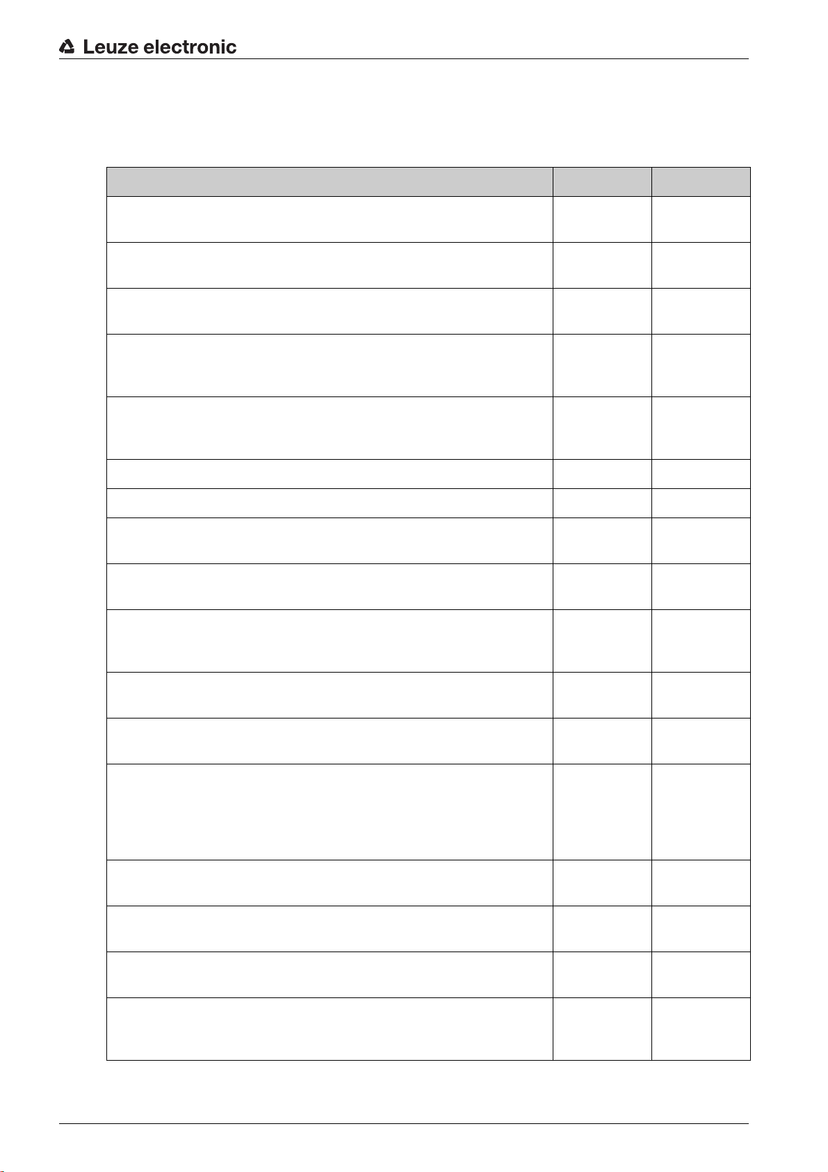
Table 1.1: Documents on the MC3x Magnetically Coded Sensors with Safety Relay
Purpose and target group Title Source
About this document
Detailed information for all
users
Basic information for technicians and operating company
MC3x Magnetically Coded Sensors
with MSI-MC3x Safety Relay
Safe implementation and operation
MC3x Magnetically Coded Sensors
with MSI-MC3x Safety Relay
Application information
1.2 Used symbols and signal words
Table 1.2: Warning symbols and signal words
Symbol indicating dangers to persons
NOTICE Signal word for property damage
Indicates dangers that may result in property damage if the measures for danger
avoidance are not followed.
CAUTION Signal word for minor injury
Indicates dangers that may result in minor injury if the measures for danger
avoidance are not followed.
WARNING Signal word for serious injury
Indicates dangers that may result in serious or fatal injury if the measures for
danger avoidance are not followed.
On the Internet, download from:
http://www.leuze.com/
Print document part no. 70002
included in the delivery contents
of the Magnetically Coded Sensor
DANGER Signal word for life-threatening danger
Indicates dangers with which serious or fatal injury is imminent if the measures
for danger avoidance are not followed.
Table 1.3: Other symbols
Symbol for tips
Text passages with this symbol provide you with further information.
Leuze electronic MC3x 5
Symbols for action steps
Text passages with this symbol instruct you to perform actions.
Page 6

About this document
Table 1.4: Terms and abbreviations
EDM External Device Monitoring
OSSD Output Signal Switching Device
RES Start/REStart interlock
PDF-M Magnetically Coded Sensors (Proximity Devices with defined behavior under
Fault conditions) with automatic monitoring (Self-Monitoring)
PDF-S Magnetically Coded Sensors (Proximity Devices with defined behavior under
Fault conditions) with Single fault tolerance
PFH
d
MTTF Mean time to a dangerous failure
PL Performance Level
2NO Two contacts in "open" state without the presence of an actuator
xxx Placeholder for version
1.3 Checklists
The checklists (see chapter 8 „Testing“) serve as a reference for the machine manufacturer or supplier.
They replace neither testing of the complete machine or system prior to the initial start-up nor their periodic
testing by a competent person. The checklists contain minimum testing requirements. Depending on the
application, other tests may be necessary.
Probability of a dangerous Failure per Hour
Probability of dangerous Failure per Hour
Mean Time To Failure
Leuze electronic MC3x 6
Page 7

2 Safety
Before using the MC3x Series, a risk evaluation must be performed according to valid standards (e.g.
EN ISO 12100-1, EN ISO 13849-1, EN ISO 14121). The result of the risk assessment determines the
required safety level of the Safety Relay, sensor and actuator.
The realizable category of integration in control circuits acc. to EN ISO 13849-1 is dependent on the used
contact block, wiring and evaluation.
For mounting, operation and testing, document “MC3x Magnetically Coded Sensors with MSI-MC3x
Safety Relay”, the application information as well as all relevant national and international standards, regu-
lations, rules and directives must be observed. Relevant and supplied documents must be observed,
printed and handed to the affected personnel.
Before working with Safety Relay, sensor and actuator completely read and understand the documents
applicable to your task.
In particular, the following national and international legal regulations apply for the start-up, technical
inspections and work with safety components:
• Machinery directive 2006/42/EC
• Electromagnetic compatibility directive 2004/108/EC
• EN 1088, Interlocking devices associated with guards
• EN 60204-1, Electrical equipment of machines
• EN 60947-5-3, Requirements for proximity switches
• Use of Work Equipment Directive 89/655/EEC supplemented by Directive 95/63 EC
• OSHA 1910 Subpart 0
• Safety regulations
• Accident-prevention regulations and safety rules
• Ordinance on Industrial Safety and Health and Labor Protection Act
• Device Safety Act
Safety
For safety-related information you may also contact the local authorities (e.g., industrial inspec-
torate, employer's liability insurance association, labor inspectorate, occupational safety and
health authority).
2.1 Approved purpose and foreseeable improper operation
WARNING
A running machine can cause severe injuries!
Make certain that, during all conversions, maintenance work and inspections, the system is securely
shut down and protected against being restarted.
Leuze electronic MC3x 7
Page 8

2.1.1 Proper use
• Safety Relay, sensor and actuator are intended for use in protective door monitoring in accordance
with EN 1088 and EN 60947-5-3.
• They are used for the safety-related monitoring of moveable guards and, thus, for the protection of
persons at entry or access areas of points of operation on machines and systems (e.g., protective
door, sliding gate, protective hoods).
• Safety Relay, sensor and actuator must only be used after they have been selected in accordance
with the respectively applicable instructions and relevant rules, standards and regulations regarding
labor protection and safety at work, and after they have been mounted on the machine, connected,
commissioned, and checked by a competent person.
• When selecting the Safety Relay, sensor and actuator, it must be ensured that their safety-related
capability meets or exceeds the required Performance Level ascertained in the risk assessment. For
the table of safety-related characteristic parameters, see chapter 13 „Technical data“.
• The MC3x sensors may only be operated with the approved MC3x actuators and MSI-MC3x Safety
Relays. Proper function with respect to safety can be ensured only if compatible components are
used.
• Safety Relay, sensor and actuator must be in perfect condition and periodically inspected by competent persons.
• If the point of operation can be reached within the stopping time of the dangerous process, a Safety
Locking Device must be used instead of the Magnetically Coded Sensor.
• The guard must be dimensioned and mounted in such a way that reaching or stepping around is not
possible.
• MC3x only reports persons upon opening of the guard, not whether persons are located in the danger zone. For this reason, a start/restart interlock in the safety chain is essential for access safeguarding.
• Sensor and actuator must be connected to the fixed or moveable guard in a permanent and tamperproof manner. The mounting conditions must be observed (see chapter 6 „Mounting“).
• The sensors and their actuators are to be protected against strong physical shocks and vibrations.
Observe the permissible environmental conditions for storage and operation (see chapter 13
„Technical data“).
• Sensor and actuator must be protected against foreign bodies (e.g., iron filings and blasting agents).
• The normally closed contacts of the MSI-MC310 are used to signal the state. Use as safety-related
contacts is not permitted.
• Sensor and actuator must be connected in such a way that a dangerous process can only be activated while the guard is closed and so that a stop command that ends the dangerous process is triggered upon opening of the guard.
• Cable gland, insulation materials and connecting wires of the appropriate protection rating are to be
used.
• Safety Relay, sensor and actuator must be replaced after a maximum of 20 years (see chapter 13
„Technical data“). Repairs or the exchange of parts subject to wear and tear do not extend the ser
vice life.
• Damaged components must be replaced immediately.
• Sensor or actuator must neither be tampered with nor may their correct position be changed.
• External magnets must not be used nor may the contacts be bridged.
• No structural changes may be made to Safety Relay, sensor or actuator. When manipulating, the
protective function is no longer guaranteed. In addition, all guarantee claims against the manufacturer shall no longer apply.
Safety
-
2.1.2 Foreseeable misuse Any use other than that defined under the “approved purpose” or which goes beyond that use of the Safety
Relay, sensor and actuator is considered improper use!
Leuze electronic MC3x 8
Page 9
Safety Relay, sensor and actuator must not be used under the following conditions, .e.g.:
• The safety of multiple persons is dependent on the function of Safety Relay, sensor and actuator
(e.g. nuclear power plants, trains, aircraft, motor vehicles, incinerators, medical devices)
• Where subjected to strong physical shocks or in potentially explosive or easily flammable atmospheres
• Danger posed by ejected objects or the spraying of hot or hazardous liquids from within the danger
zone
• Presence detection of persons in danger zones
• Looping into the safety circuit parts that are not relevant to safety
• The combination of non-approved parts with Safety Relay, sensor or actuator
• Combination with non-compatible controls (current limiting, logic)
• Mounting positions that enable reaching or stepping around
• Using the sensor or actuator as limit stop
• Insufficiently stable mounting locations or unsecured mounting of sensor or actuator
• Mounting on ferromagnetic materials.
2.2 Competent persons
Prerequisites for competent persons:
• They have a suitable technical education.
• They know the rules and regulations for occupational safety, safety at work and safety technology
and can assess the safety of the machine.
• They know the instructions for the safety components and the machine.
• They have been instructed by the responsible person on the mounting and operation of the machine,
the Safety Relay and the sensor with actuator.
Safety
2.3 Responsibility for safety
Manufacturer and operating company must ensure that the machine and Safety Relay, sensor and actu-
ator used function properly and that all affected persons are adequately informed and trained.
The type and content of all imparted information must not lead to unsafe actions by users.
The manufacturer of the machine is responsible for:
• safe machine construction
• safe implementation of Safety Relay, sensor and actuator
• imparting all relevant information to the operating company
• adhering to all regulations and directives for the safe starting-up of the machine
The operating company is responsible for:
• instructing the operator
• maintaining the safe operation of the machine
• adhering to all regulations and directives for occupational safety and safety at work
• regular testing by competent persons
2.4 Exemption of liability
Leuze electronic GmbH & Co. KG is not liable in the following cases:
• Safety Relay, sensor and actuator are not used as intended
• Reasonably foreseeable misuse is not taken into account
• Safety notices are not adhered to
• Mounting and electrical connection are not properly performed
• Proper function is not tested (see chapter 8 „Testing“).
• Combination of sensor and actuator with controls,
• which have not been designed to be safety-oriented
Leuze electronic MC3x 9
Page 10

• for which the current limits are not compatible
• which have not been programmed to be compatible with the respective contact set
• although a PDF system certified in accordance with EN 60947-5-3 was provided
Safety
Leuze electronic MC3x 10
Page 11

3 Device description
1
2
3
1
1
2
2
The sensor system consists of the MC3x sensor, the MC3xA actuator and the corresponding MSI-MC3x
Safety Relay.
The sensor contains a special combination of reed contacts that are contactlessly activated by the coded
magnetic field of the actuator. For guards that are accessible from behind, a reset button (RES) can be
connected to the MSI-MC3x for manual starting. Evaluation of the RES signal is monitored edge-depen-
dent.
If, for example, a door is opened, the actuator mounted here is separated from the sensor, which is located
on the stationary part of the guard. If the change in the position of the actuator reaches the maximum value
of the defined distance, the switching state is detected by the Safety Relay connected to the sensor and
is signaled to the control via two fail-safe OSSD contacts.
As a result, risky machine movements can only be executed while the guard is closed or if a stop command
is executed while the guard is being opened.
Moreover, additional switching elements can be integrated in the safety circuit. The monitoring of relays or
contactors is possible via their feedback contacts K3, K4 in the start circuit of the MSI-MC3x.
Due to the closed design of the sensors, they can also be used in critical environmental conditions (e.g.,
in areas where there is exposure to dust).
The system offers a high degree of safety and satisfies the following standards:
• Performance Level (PL) e (EN ISO 13849-1: 2008)
• Safety category 4 (EN ISO 13849-1:2008)
Depending on the application, various MC3x series are available.
Device description
1 Sensor
2 Actuator
3 Safety Relay
Figure 3.1: MC3x series with MSI-MC3x
Leuze electronic MC3x 11
Page 12

3.1 Device overview
Table 3.1: Overview of the product variants of the MC3x series with contact set 1NC/1NO
Device description
Sensor Housing Switching distance
Sao /OFF/ Sar
MC388-S1x Cuboid
< 6 mm, > 13 mm, > 30 mm 2 m-, 5 m-, 10 m-PVC con-
max. 88 mm x 25 mm
MC336-S1x Cuboid
< 3 mm, > 8 mm, > 11 mm 2 m-, 5 m-, 10 m-PVC con-
max. 36 mm x 26 mm
Connection
nection cable with wire-end
sleeves
2 m, 5 m, 10 m PUR connection cable with wire-end
sleeves
0.2 m PVC connection
cable with M12 plug
M8 plug
nection cable with wire-end
sleeves
2 m, 5 m, 10 m PUR connection cable with wire-end
sleeves
0.2 m PVC connection
cable with M12 plug
M8 plug
MC330-S1x Cylinder
max. 30 mm, round
< 6 mm, > 12 mm, > 14 mm 2 m-, 5 m-, 10 m-PVC con-
nection cable with wire-end
sleeves
2 m, 5 m, 10 m PUR connection cable with wire-end
sleeves
0.2 m PVC connection
cable with M12 plug
M8 plug
Table 3.2: Overview of the product variants of the MC3x series with contact set 2NO
Sensor Housing Switching distance
Connection
Sao /OFF/ Sar
MC388-S2x Cuboid
max. 88 mm x 25 mm
< 9 mm, > 19 mm, > 22 mm 2 m-, 5 m-, 10 m-PVC con-
nection cable with wire-end
sleeves
0.2 m PVC connection
cable with M12 plug
M8 plug
Leuze electronic MC3x 12
Page 13

Device description
Sensor Housing Switching distance
Connection
Sao /OFF/ Sar
MC336-S2x Cuboid
max. 36 mm x 26 mm
< 7 mm, > 17 mm, > 20 mm 2 m-, 5 m-, 10 m-PVC con-
nection cable with wire-end
sleeves
0.2 m PVC connection
cable with M12 plug
M8 plug
MC330-S2x Cylinder
max. 30 mm, round
< 6 mm, > 15 mm, > 18 mm 2 m-, 5 m-, 10 m-PVC con-
nection cable with wire-end
sleeves
0.2 m PVC connection
cable with M12 plug
M8 plug
Table 3.3: Overview of MSI-MC3x Safety Relays
Safety Relays Functions Output contacts Safety
MSI-MC310 Evaluation of MC3xS1x
sensors (1NC/1NO), RES,
EDM
Safety-related relay contacts 2 normal open contacts (N/O) / non-safetyrelated relay
contact 1 normal closed
contact (N/C)
Up to PL e and cat. 4
(EN 13849-1) with connection of one sensor
Up to PL e and cat. 3
(EN 13849-1) with connection of more than one sensor
MSI-MC311 Evaluation of MC3xS2x
sensors (2NO), RES, EDM
Safety-related relay contacts 2 normal open contacts (N/O)
Up to PL e and cat. 4
(EN 13849-1) with connection of one sensor
Up to PL e and cat. 3
(EN 13849-1) with connection of more than one sensor
Figure 3.2: Design MC388x Figure 3.3: Design MC336x Figure 3.4: Design MC330x
Leuze electronic MC3x 13
Page 14

1 Connection terminals
24
S11
31
OUT
A2
A1
23
SR
13
A
S22
S33
S34
S12
32
14
MSI-MC310
Supply
K2
K1
1
2
3
4
5
1
2
3
4
5
1
2
3
2 Voltage indicator
3 Status K1
4 Status K2
5 Connection terminals
Figure 3.5: MSI-MC310 and MSI-MC311 Safety Relays
Device description
LED State Meaning
Supply Green illuminated Voltage supply switched on
K1 Green illuminated Input condition for K1 fulfilled
K2 Green illuminated Input condition for K2 fulfilled
Figure 3.6: Designation locations, MC3x series sensors
1 Date of manufacture
2 Order number
3 Designation
Leuze electronic MC3x 14
Page 15

4 Functions
Table 4.1: Overview of the safety functions
Short description of the functions
Stop function Safety-related; initiated by the guard
Start/restart interlock Prevents automatic restart; forces manual confirmation via a reset button
Automatic start/restart Automatic operation without use of a reset button
RES (restart) Manual start by means of a reset button for guards that are accessible
EDM External Device Monitoring (contactor monitoring)
Display technology LEDs, display for K1, K2 input condition as well as for voltage supply
OSSDs Safety-related switching outputs (relays)
4.1 Start/restart interlock
(Connection of the reset button between pin OUT / 24 V and pin SR of the MSI-MC310)
(Connection of the reset button between pin A2 and pin SR1 / SR2 of the MSI-MC311)
The start/restart interlock prevents automatic release of the safety circuits and automatic start-up of the
system (e.g., if the protective door closes again or an interruption of the voltage supply is restored).
The system may not be manually released with the reset button until no persons are located in the danger
zone (see chapter 7.7 „Unlocking start/restart interlock“).
Functions
(RES)
from behind
4.2 Automatic start/restart
(Bridge between pin OUT / 24 V and pin A of the MSI-MC310)
(Bridge between pin SR1 / SR2 and pin EDM of the MSI-MC311)
The automatic start/restart interlock enables immediate release of the safety circuits and automatic start-
up of the system (e.g., if the protective door closes again or an interruption of the voltage supply is
restored).
This operating mode is only permitted if it is not possible to reach or step behind the guard (see chapter 7.7
„Unlocking start/restart interlock“).
4.3 Contactor monitoring (EDM)
(Connection in the start circuit between pin OUT and pin SR of the MSI-MC310)
(Connection in the start circuit between pin S12 and PIN EDM of the MSI-MC311)
The MSI-MC310 / MSI-MC311 monitors the feedback circuits of the connected relays or contactors.
The two OSSDs are not activated until:
• all actuators of the connected sensors are in the specified distance range
• all connected sensors are activated
• opening of the contacts (reset button, EDM contacts) causes the signal at pin SR to drop out
Leuze electronic MC3x 15
Page 16

5 Applications
The MC3x series is used in position monitoring of moveable guards, e.g. (sliding) gates, flaps or hoods.
WARNING
Unexpected machine start-up may cause severe injuries.
If the guard is accessible from behind, e.g., in the case of access guarding of danger zones, only the
opening of the door is detected; persons present within the danger zone are not detected after the door
is closed.
Only operate access guarding in the start/restart interlock operating mode or take additional safety
measures.
Applications
Figure 5.1: Access guarding on a PCB production line, implemented on a door with MC330x sensors
Leuze electronic MC3x 16
Page 17

Applications
Figure 5.2: Access guarding on a filling system, realized on a door with MC388x sensors
Figure 5.3: Access safeguarding on a small painting robot, implemented on a hood with MC336x sen-
sors
Leuze electronic MC3x 17
Page 18

Applications
Figure 5.4: Access safeguarding on a food production line, implemented on a sliding gate with MC336x
sensors
Figure 5.5: Access safeguarding on a beverage filling system, implemented on a raisable window with
MC336x sensors
Leuze electronic MC3x 18
Page 19
6 Mounting
WARNING
Improper mounting may result in serious injury!
The protective function of the sensors is only ensured if used in the intended area of application and if
they are mounted professionally.
Mounting may only be performed by competent persons.
Observe the relevant standards, regulations and these instructions.
Do not use the sensor in areas under the influence of strong magnetic fields.
After mounting, check the sensors for proper function
6.1 Selecting the position and arrangement of sensor and actuator
WARNING
Improper mounting may result in serious injury!
The protective function of the sensors is only ensured if, after the guard is opened, the dangerous
process can be safely stopped before it is reached by a person.
Mount the sensors with an adequate safety distance to the danger zone.
Take all delay times into account (e.g., the response times of the control elements, the stopping time
of the machine)
Mounting
Select the mounting locations so that the following conditions are satisfied acc. to EN 1088:
• For doors/flaps that swing open, the position of sensor and actuator is opposite the hinge side.
• The position of sensor and actuator allows the cut-out distance Sar to be reached upon opening of
the moveable guard.
• The position of sensor and actuator makes it impossible to reach or step behind the moveable guard.
• Make certain that the gap dimension between the fixed and moveable part of the guard is not wide
enough for reaching or stepping behind.
• The position of sensor and actuator makes it impossible for a person to reach the dangerous area
during the stopping time of the machine after the guard is opened.
• The position protects the sensor from physical shocks and vibrations that exceed specifications (see
chapter 13 „Technical data“).
• Adjacent Magnetically Coded Sensors must be separated by at least 50 mm.
• The position of sensor and actuator must not lie within the range of influence of blasting agents or
magnetic particles.
• Mounting on ferromagnetic materials (e.g., iron, nickel, cobalt) is to be avoided.
• When mounting on stainless steel surfaces, spacers are to be used and the safety-related switching
distances are to be inspected.
• The position of sensor and actuator must facilitate form-fitting mounting.
• Accessible to qualified personnel for testing and replacement
• Cannot be manipulated by operators though removal, turning, short-circuiting (e.g., by means of covered mounting)
NOTICE
Faulty or incorrect alignment will result in an operating fault.
The alignment of sensor and actuator within the scope of start-up is to be performed only by trained
personnel.
Observe the data sheets and mounting instructions of the individual components.
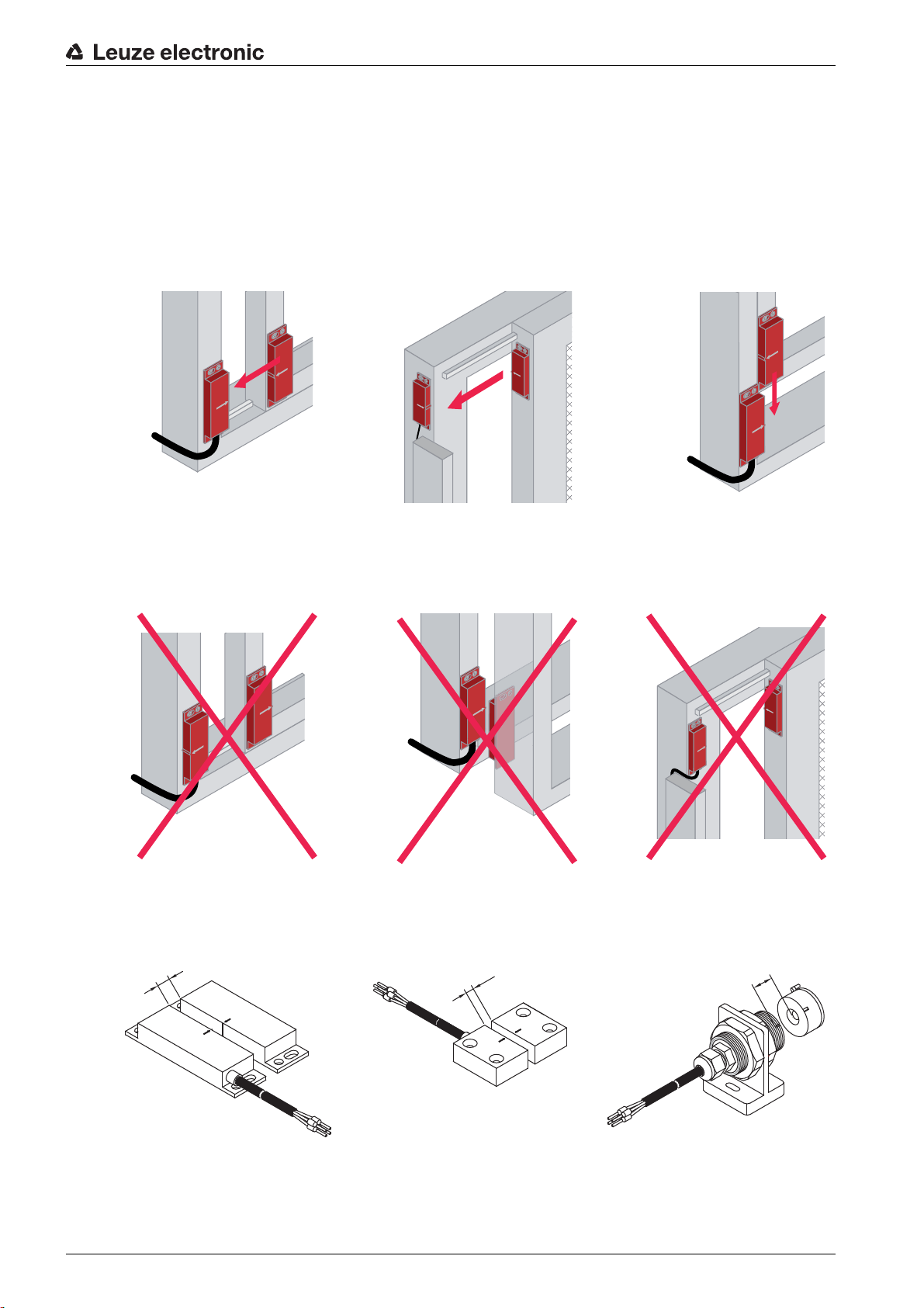
Aligning on the basis of the markings, approach directions
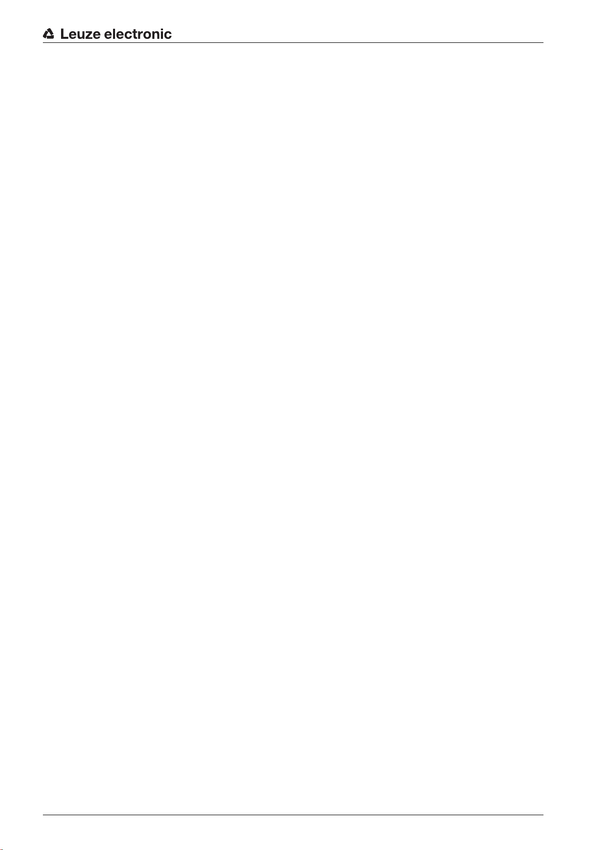
In the following example, the MC388x sensor is mounted on the front of a sliding gate. The switching condi-
tion is activated by the actuator approaching from below.
Leuze electronic MC3x 19
Page 20
Mounting
Figure 6.1: Approach direction from below
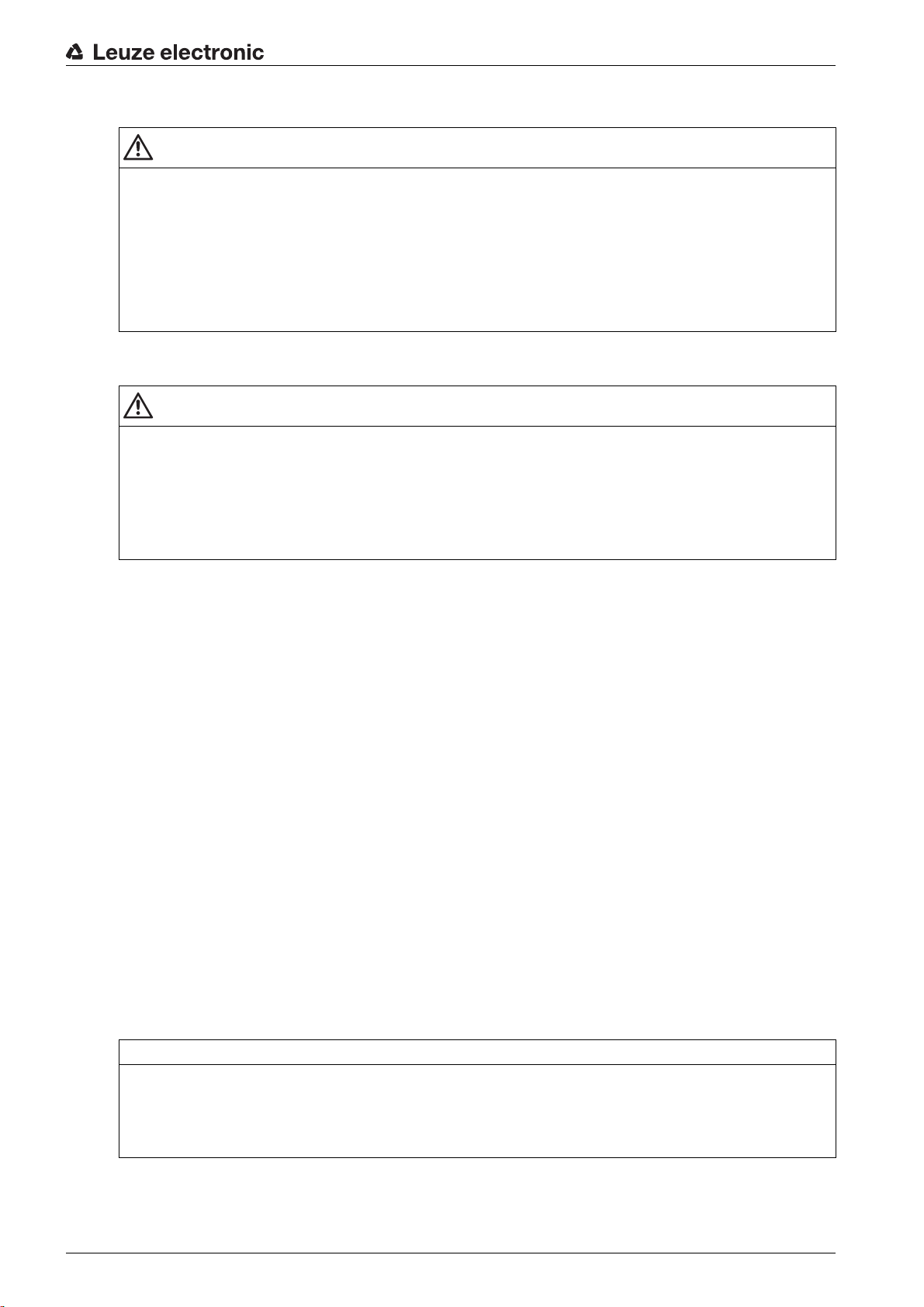
In the following example, the MC388x sensor is mounted on the front of a swinging door and is protected.
The switching condition is activated by the actuator approaching on the same level.
Figure 6.2: Approach direction on the same level
In the following example, the MC336x sensor is mounted on a small sliding window and is protected. The
switching condition is activated by the actuator approaching on the same level.
Leuze electronic MC3x 20
Page 21

Mounting
Figure 6.3: Approach direction on the same level
In the following example, the MC336x sensor is mounted on a vertically moving sliding window and is
protected. The switching condition is activated by the actuator approaching from the side.
Figure 6.4: Approach direction, from side
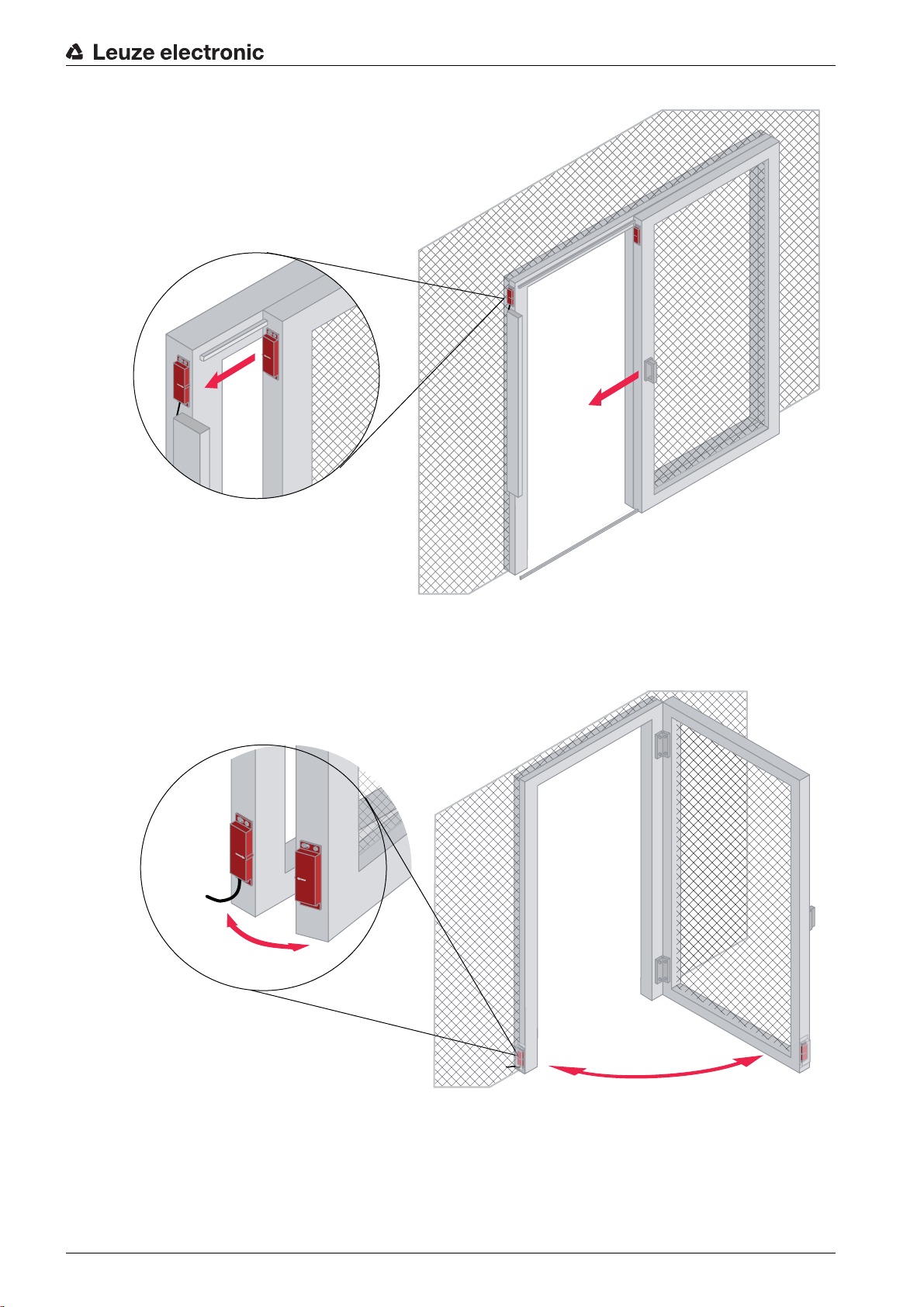
In the following example, the MC330x sensor is mounted recessed on the front of a sliding gate. The
switching condition is activated by the actuator approaching on the same level.
Leuze electronic MC3x 21
Page 22
Mounting
Figure 6.5: Approach direction on the same level
6.2 Mounting and aligning sensor and actuator
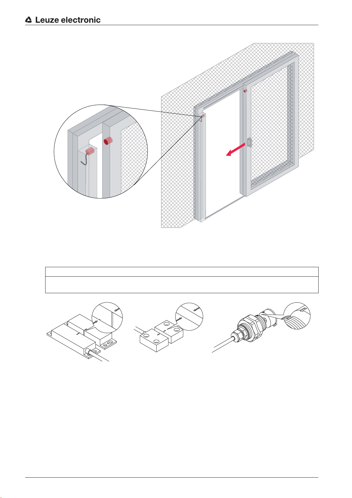
NOTICE
Observe the switching distances and ensure that the markings on sensor and actuator line up while the
guard is closed.
Figure 6.6: MC388x Figure 6.7: MC336x Figure 6.8: MC330x
Proceed as follows:
Select the position of the sensor on the fixed part of the guard (see chapter 6.1 „Selecting the position
and arrangement of sensor and actuator“).
Select the position of the actuator on the moveable part of the guard (see chapter 6.1 „Selecting the
position and arrangement of sensor and actuator“).
Drill the bore holes acc. to the specified dimensions (see chapter 14 „Dimensions and weights“).
For round actuators, take into account the anti-twist protection by providing an appropriate recess.
Loosely screw the sensor and actuator at the defined positions. Use the washers.
Align sensor and actuator with one another so that when the guard is closed, the markings (e.g., arrows,
notches, lines) are aligned, i.e., are opposite one another. A lateral offset reduces the switching distance.
Leuze electronic MC3x 22
Page 23
Mounting
a
a
Align sensor and actuator with one another so that while the guard is closed, they do not touch one
another (minimum distance: 1 mm).
Do not consider sensor and actuator to be limit stops.
Make certain that the cut-in and cut-out points (Sao, OFF, Sar see table 6.1) can be reached without
mechanical tension in the moveable guard.
Secure sensor and actuator within the specified distance values "Sao" and "OFF".
After aligning, permanently fasten sensor and actuator with locking screws (to 10 Nm).
Correct alignment
Figure 6.9: The markings are
Figure 6.10: The markings
aligned on the
same level.
Incorrect alignment
Figure 6.12: The markings are
Figure 6.13: The markings
not aligned with
one another.
Switching distances from sensor to actuator
are aligned from
below.
are not aligned.
Figure 6.11: The markings
are laterally
aligned.
Figure 6.14: The markings
are not
aligned.
a
Figure 6.15: MC388x
a see table switch-
ing distance
a see table
switching distance
a see table switching
distance
Figure 6.17: MC330x
Figure 6.16: MC336x
Leuze electronic MC3x 23
Page 24
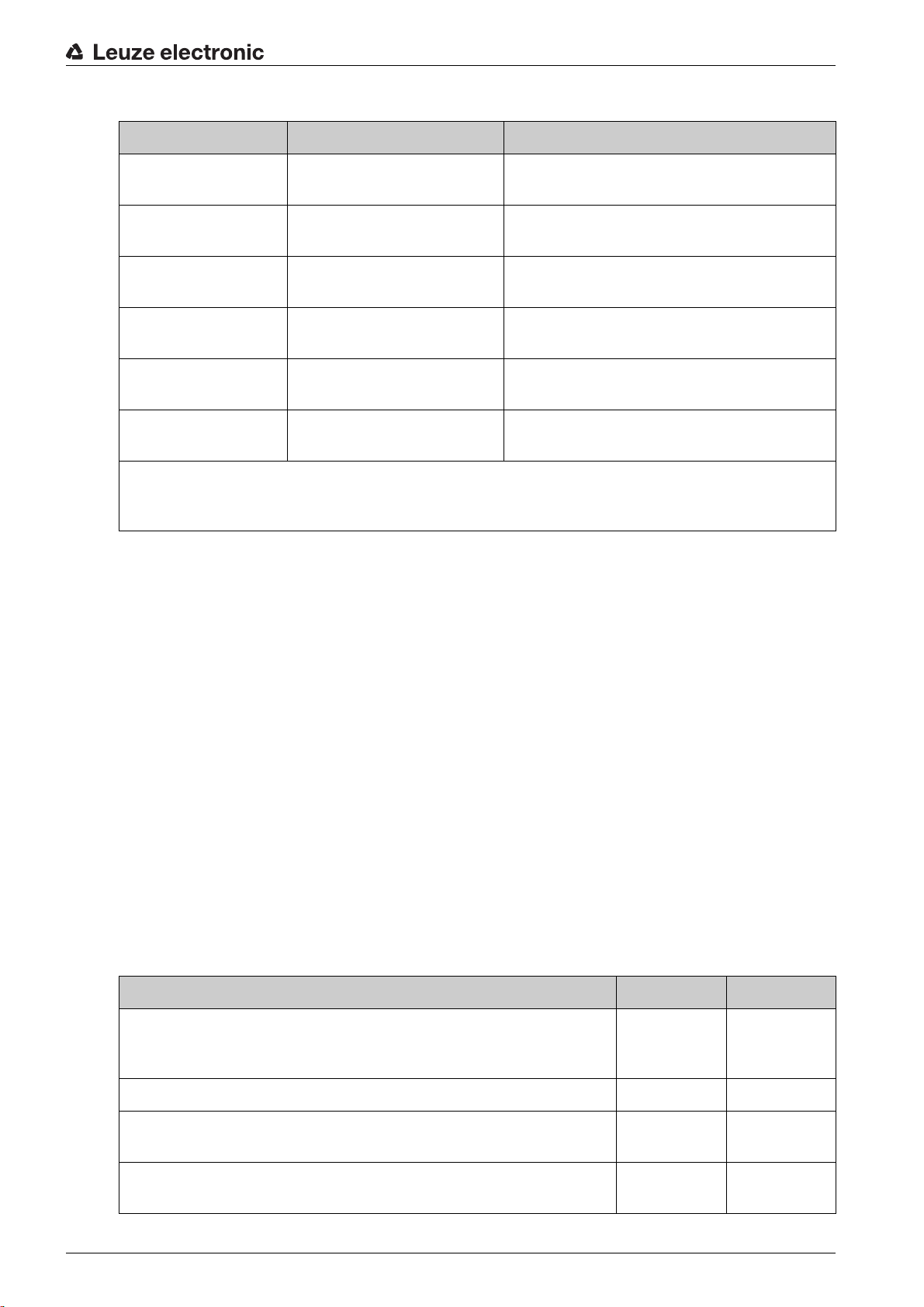
Table 6.1: Switching distances of sensor and actuator
Sensor type Housing Switching distance Sao / OFF / Sar
Mounting
MC388-S1-A Cuboid
< 6 mm, > 13 mm, > 30 mm
88 mm x 25 mm
MC336-S1-A Cuboid
< 3 mm, > 8 mm, > 11 mm
36 mm x 26 mm
MC330-S1-A Cylinder
< 6 mm, > 12 mm, > 14 mm
30 mm, round
MC388-S2-A Cuboid
< 9 mm, > 19 mm, > 22 mm
88 mm x 25 mm
MC336-S2-A Cuboid
< 7 mm, > 17 mm, > 20 mm
36 mm x 26 mm
MC330-S2-A Cylinder
< 6 mm, > 15 mm, > 18 mm
30 mm, round
Sao = assured cut-in distance
OFF = cut-out point
Sar = assured cut-out distance
Proceed as follows:
Align the actuator so that the distance between sensor and actuator is within the specifications (Sao and
OFF) while the guard is closed.
The fitting position of sensor and actuator can be freely selected.
If necessary, provide a constraining guide for the moveable part of the guard. The edges of the move-
able and fixed part of the guard must be aligned (e.g., door and frame).
Do not use the sensor as a limit stop, but rather provide a separate mechanical limit stop.
Install a locking or snap mechanism for the moveable part of the guard to prevent it from swinging open.
If it is expected that the moveable part of the guard will warp, the mounting position of sensor and actu-
ator can be adjusted to offset this somewhat if necessary. Check the resulting gap dimensions to determine, e.g., whether it allows a person to reach behind.
Fasten sensor and actuator with rivets or tamperproof screws on a form-fitting surface so that they can-
not be detached.
If necessary, mount sensor and actuator so they are covered.
Note the minimum approach speed (see chapter 13 „Technical data“).
6.2.1 Checklist - correct mounting of sensor and actuator Area of application: Mounting
Tester: Technician who mounts the MC3x
Checklist for mounting Yes No
Are sensor, actuator and Safety Relay properly selected, i.e., not
mixed, and used acc. to the assignment (see chapter 15 „Ordering
information and accessories“)?
Are sensor and actuator mounted in a form-fitting manner?
While the guard is closed, is the distance from sensor and actuator
within the specified values Sao and OFF?
Do the markings on sensor and actuator align while the guard is
closed?
Leuze electronic MC3x 24
Page 25
Checklist for mounting Yes No
Is it ensured that sensor and actuator do not serve as a limit stop?
Are sensor and actuator fastened in such a way that they cannot be
moved and turned?
Is a separate limit stop with locking or snap mechanism mounted?
Is the distance to other Magnetically Coded Sensors and their actuators
maintained?
Are sensor and actuator accessible for inspection and replacement?
Is access to the point of operation/to the danger zone possible only
through the monitored, moveable part of the guard?
Can the point of operation be reached only after the dangerous movement has stopped?
Have measures been taken to prevent the guard from being bypassed
by crawling under or reaching or jumping over?
Is it impossible to actuate the start/restart button from within the danger
zone?
Mounting
Can the entire danger zone be seen from the installation site of the
start/restart button?
Are the edges of the moveable and fixed part of the guard aligned (e.g.,
door and frame); no warping or deformation?
6.3 Mounting the Safety Relay
WARNING
Improper mounting may result in serious injury!
The protective function of the Safety Relay is only ensured if appropriately and professionally mounted
for the respective, intended area of application.
Only allow competent persons to install the Safety Relay.
Observe the relevant standards, regulations and these instructions.
Prerequisites for mounting:
• Cabinet with appropriate protection rating (at least IP 54, NEMA 3)
• 35 mm-DIN top-hat supporting rail in accordance with DIN EN 50022
• Snap the Safety Relay onto the DIN rail.
• The Safety Relay can be connected to the sensors.
NOTICE
The Safety Relay may be damaged if mounted improperly!
The MSI-MC310/311 is not suitable for free wall mounting .
Depending on the environmental conditions at the end user, a suitable protective housing type must
be determined and used.
Leuze electronic MC3x 25
Page 26

7 Electrical connection
WARNING
Risk of death by electric shock!
Depending on external wiring, dangerous voltages may be present at the switching outputs.
During all work at the electrical system or electronics, make certain that each voltage supply has been
interrupted and protected against being restarted.
The following must be observed for the current supply of the Safety Relay:
• The supply voltage must be 24 V DC (see chapter 13 „Technical data“).
• Acc. to EN 61558-2-6, the cables at the inputs are to be separated from mains by either a safety isolating transformer with limited output voltage in the case of failure or by means of appropriate isolation measures.
WARNING
Improper electrical connection may result in serious injury!
Only allow competent persons to perform the electrical connection.
Make certain that supply and signal lines are laid separately from power lines.
Provide appropriate spark extinction for contactors/sequence relays in the cabinet.
Observe the installation and operating information for the products that are to be connected via the
Safety Relay (e.g., drive motors, brakes, etc.).
Electrical connection
The following conditions apply for the electrical connection:
• The Safety Relay must be integrated in the control circuit acc. to EN ISO 13849-1/-2:2009.
• The cables must be laid separately/in a protected manner, acc. to EN ISO 13849-1/-2:2009.
• Shutdown of the supply voltage for operational purposes is not permissible.
• If only one sensor is used, the free inputs must be bridged.
• It is not permissible to connect the sensor lines in parallel with third-party components.
• The mixed connection of protective extra low voltage and low voltage (e.g., 240 V
14, 23/24, 31/32 is not permissible.
• To prevent welding of the MSI output contacts, an external fuse is required acc. to the technical
specifications of the MSI-MC3x (see chapter 13.3 „MSI-MC310 Safety Relay“ or see chapter 13.4
„MSI-MC311 Safety Relay“) and for any other connected components.
• The OUT terminal (MSI-310) is not for operating external devices, but is rather intended only for supplying potential-free contacts.
7.1 Terminal assignments of the Safety Relay
WARNING
Selecting the wrong functions may result in serious accidents!
Activate restart interlock if it is possible to reach or walk behind.
For access guarding, make certain that the restart interlock cannot be unlocked from within the danger
zone but that the danger zone can be viewed from the reset button (RES).
Select the functions so that the Safety Relay is used as intended (see chapter 2.1 „Approved purpose
and foreseeable improper operation“).
~) at terminals 13/
There are 16 terminals on the Safety Relay for connecting the cables. The connection of the Safety Relay
is divided into sensor groups, additional functions, OSSDs and supply voltage.
Leuze electronic MC3x 26
Page 27

7.1.1 MSI-MC310 Safety Relay
24
S11
31
OUT
A2
A1
23
SR
13
A
S22
S33
S34
S12
32
14
MSI-MC310
Supply
K2
K1
Electrical connection
Figure 7.1: MSI-MC310, terminal assignments
Table 7.1: MSI-MC310, terminal designations
Terminal des-
Function Description
ignation
A1, A2 Input Voltage supply
S11 Output For sensor 1, contact NO + sensor 2/x, contact NO
S12 Input Sensor 1, contact NO
S22 Input Sensor x, contact NO
S33 Output Sensor 1, contact NC + sensor 2/x, contact NC
S34 Input Sensor 1, contact NC + sensor 2/x, contact NC
OUT Output For start- and EDM circuit
SR Input For start- and EDM circuit
A Input For “automatic” operating mode with or without EDM
13/14 Relay contacts OSSD 1, safety-related release circuit 1
23/24 Relay contacts OSSD 2, safety-related release circuit 2
31/32 Relay contacts EDM-, signaling circuit
Table 7.2: MSI-MC310, evaluation and bridging
Evaluation Safety level Connection, terminal Bridging, if the adjacent termi-
nal group is not needed
1 sensor PL e, cat. 4, PDF-M S11
1 sensor S33
Leuze electronic MC3x 27
® NO ® S12 S11 ® bridge ® S22
® NC ® S34
Page 28

Electrical connection
1
4
2
3
1
3
2
4
Evaluation Safety level Connection, terminal Bridging, if the adjacent termi-
nal group is not needed
2 sensors PL e/d, cat. 3, PDF-S S11
2 sensors S33
x sensors PL e/d, cat. 3, PDF-S S11
x sensors S33
® NO(1) ® S12 and
S11
® NO(2) ® S22
® NC(1) ® S34 and
S33
® NC(2) ® S34
® NO(1) ® NO(2) to
NO(x)
® S12
® NC(2) ® S34 to S33
® NC(x) ® S34
Table 7.3: MSI-MC310, evaluation and operating mode
Evaluation Operating mode Connection, terminal
Reset button
RS OUT
® (RES) ® SR
(RES)
Reset button
RS, EDM OUT
® (RES) ® EDM ® SR
(RES) and
contactor
Contactor Autom. start, EDM OUT
Autom. start OUT
® EDM ® A
® bridge ® A
® bridge ® S22
S11
7.1.2 Sensor pin assignment (1NC/1NO) The MC3x sensors (1NC/1NO) are equipped with either M8, M12 connectors or with a PVC or PUR
connection cable, in various lengths and with wire-end sleeves.
1Brown
2White
3Blue
4Black
Figure 7.2: Wire assignment, colors of the connection cable, state without activation by actuator
Pin 1 Brown
Pin 2 White
Pin 3 Blue
Pin 4 Black
Figure 7.3: Pin assignments of the M8 connector
Leuze electronic MC3x 28
Page 29

Pin 1 Brown
2
4
3
1
Pin 2 White
Pin 3 Blue
Pin 4 Black
Figure 7.4: Pin assignments of the M12 connector
7.1.3 MSI-MC311 Safety Relay
Electrical connection
Figure 7.5: MSI-MC311, terminal assignments
Table 7.4: MSI-MC311, terminal designations
Terminal des-
Function Description
ignation
A1, A2 Input Voltage supply
S11 Input Contact 1, NO
S12 Output Contact 1, NO
S21 Input Contact 2, NO
S22 Output Contact 2, NO
SR1 Input Start circuit 1
SR2 Input Start circuit, bridged
SI Relay contact input Status
S01 Relay contact output Status off
S02 Relay contact output Status on
Leuze electronic MC3x 29
Page 30

Electrical connection
1
4
2
3
Terminal des-
Function Description
ignation
EDM Input EDM circuit
13/14 Relay contacts OSSD 1, safety-related release circuit 1
23/24 Relay contacts OSSD 2, safety-related release circuit
Table 7.5: MSI-MC311, evaluation and bridging
Evaluation Safety level Connection, terminal
1 sensor PL e, cat. 4, PDF-M S11
2 sensors PL e/d, cat. 3, PDF-S S11
x sensors PL e/d, cat. 3, PDF-S S11
® NO ® S12
S21
® NO ® S22
® NO(11) ® NO(21) ® S12
S21
® NO(12) ® NO(22) ® S22
® NO(11) ® NO(21) ® NO(x1) ® S12
S21
® NO(12) ® NO(22) ® NO(x2) ® S22
Table 7.6: MSI-MC311, evaluation and operating mode
Evaluation Operating mode Connection, terminal Bridging
Reset button
RS, single-channel A2
(RES)
Contactors K3, K4EDM S12
Autom. start EDM
7.2 Sensor pin assignment (2NO)
The MC3x sensors (2NO) are equipped with either M8, M12 connectors or with a PVC or PUR connection
cable, in various lengths and with wire-end sleeves.
1Brown
2White
3Blue
4Black
Figure 7.6: Wire assignment, colors of the connection cable, state without activation by actuator
® (RES) ® SR1 SR1 ® bridge ® SR2
® K3, K4® EDM
® bridge ® SR1
EDM
® bridge ® SR2
Leuze electronic MC3x 30
Page 31

Pin 1 Brown
1
3
2
4
2
4
3
1
Pin 2 White
Pin 3 Blue
Pin 4 Black
Figure 7.7: Pin assignments of the M8 connector
Pin 1 Brown
Pin 2 White
Pin 3 Blue
Pin 4 Black
Figure 7.8: Pin assignments of the M12 connector
Electrical connection
7.3 Connection examples
Prerequisites for the electrical connection:
• The maximum temperature of the application does not exceed that specified in the technical data of
the sensors (see chapter 13 „Technical data“)
• Contact assignments are adhered to
Lay sensor connection cable and connect according to the assignment specifications and the applica-
tion-specific circuit diagram.
Connect the MSI-MC3x according to the application-specific circuit diagram.
Setting the device into service
NOTICE
Improper electrical connection may result in serious injury!
The mixed connection of protective extra low voltage and low voltage at terminals 13/14, 23/24 and
31/32 (MSI-3x) is not permitted.
Finger-safe acc. to DIN VDE 0106 part 100, maximum stripped length of the connection cables: 8 mm
To prevent welding of the respective output contacts, an external fuse must be connected upstream.
All reactive loads connected to the supply voltage are to be provided with interference-suppression cir-
cuits.
For reactive loads on terminals 13/14, 23/24, 31/32 (MSI-3x), an appropriate protective circuit is to be
provided.
Shutdown of the supply voltage for operational purposes is to be made impossible.
7.3.1 Connection examples with MC3xS1x sensors and MSI-MC310 Safety Relay The following examples show possible connection combinations of Magnetically Coded Sensors on the
Safety Relay for contact set 1NC/1NO.
All available safety inputs must be occupied. Bridges are to connect the remaining inputs where no
sensors are connected .
Leuze electronic MC3x 31
Page 32

Electrical connection
The following wiring diagram shows the connection of an MC3xS1x for achieving safety category 4 and
Performance Level e. For access safeguarding, it also includes the “start/restart interlock” operating mode
and a reset button.
0V
MC3xS1x
K3
+24V
K4
MSI-MC310
A1
S11
S12
S22
S33
S34
OUT
SR
A
A2
Figure 7.9: Example 1: Two-channel connection of an MC3xS1x with start/restart interlock and contactor
monitoring (EDM), contact drawing without activation by actuator
The following wiring diagram shows the connection of two MC3xS1x for achieving safety category 3 and
Performance Level e or d. If the guard cannot be reached or stepped around the “Automatic start/restart”
operating mode is permissible for the benefit of an efficient system design.
0V
MC3xS1x
MC3xS1x
K3
MSI-MC310
+24V
K4
A1
S11
S12
S22
S33
S34
OUT
SR
A
A2
Figure 7.10: Example 2: Connection of two MC3xS1x with automatic start/restart interlock and contactor
monitoring (EDM), contact drawing without activation by actuator
The following wiring diagram shows the connection of four MC3xS1x on two doors for achieving safety
category 3 and Performance Level e or d.
Leuze electronic MC3x 32
Page 33
Electrical connection
0V
MSI-MC310
S11
S12
S22
OUT
S34
A2
S33
+24V
A1
A
SR
MC3xS1x
MC3xS1x
MC3xS1x
MC3xS1x
Var. B
Var. A
MSI-MC310
0V
-K3
-A1
-A2
-K4
-K4
-K3
0V
PE
PE
0V
13 23A1 S11 S12 S22 S33 S34 OUT
31
-S1
-K3
-K4
+24V
A2 14 24
A1
A2
-K3
L- L-
32
*
A1
A2
-K4
1
2
1
2
L+ L+
+24V
+24V
SR A
MC3xS1x
MC3xS1x
MC3xS1x
MC3xS1x
No. x
No. 3
No. 2
No. 1
*
Figure 7.11: Example 3: Connection of four MC3xS1x with start/restart interlock, contact drawing without
activation by actuator
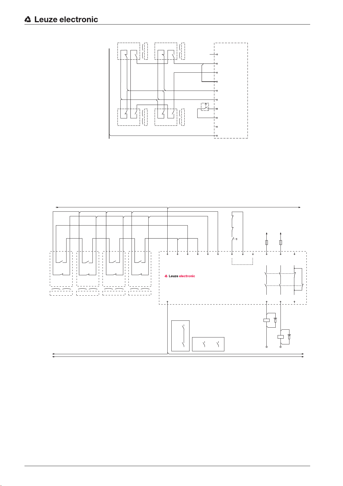
The following wiring diagram shows the connection of several MC3xS1x for achieving safety category 3
and Performance Level e or d in the case of access safeguarding (start/restart interlock, EDM). Up to 30
moveable guards can be monitored in this way. Safeguarding in the switch-off circuit must satisfy the spec-
ifications for K1, K2 as well as those of the downstream contactors.
*) Spark extinction circuit, suitable spark extinction provided
Figure 7.12: Example 4: Connection of several MC3xS1x with start/restart interlock and contactor moni-
toring (EDM), contact drawing without activation by actuator
7.3.2 Connection examples with MC3xS2x sensors and MSI-MC311 Safety Relay The following examples show possible connection combinations of Magnetically Coded Sensors on the
Safety Relay for contact set 2NO.
All available safety inputs must be occupied. Bridges are to connect the remaining inputs where no
sensors are connected .
The following wiring diagram shows the connection of an MC3xS2x for achieving safety category 4 and
Performance Level e. For access safeguarding, it also includes the “start/restart interlock” operating mode
and a reset button
Leuze electronic MC3x 33
Page 34

Electrical connection
0V
MSI-MC311
S11
S12
EDM
S22
A2
S21
+24V
A1
SR2
SR1
MC3xS2x
K3
K4
0V
MSI-MC311
S11
S12
EDM
S22
A2
S21
+24V
A1
SR2
SR1
MC3xS2x
K3
K4
MC3xS2x
Figure 7.13: Example 1: Two-channel connection of an MC3xS2x with start/restart interlock and contactor
monitoring (EDM), contact drawing without activation by actuator
The following wiring diagram shows the connection of two MC3xS2x for achieving safety category 3 and
Performance Level e or d. If the guard cannot be reached or stepped around the “Automatic start/restart”
operating mode is permissible for the benefit of an efficient system design.
Figure 7.14: Example 2: Connection of two MC3xS2x with automatic start/restart and contactor monitor-
ing (EDM), contact drawing without activation by actuator
The following wiring diagram shows the connection of several MC3xS2x for achieving safety category 3
and Performance Level e or d in the case of access safeguarding (start/restart interlock, EDM). Up to 30
moveable guards can be monitored in this way. Safeguarding in the switch-off circuit must satisfy the spec-
ifications for K1, K2 as well as those of the downstream contactors.
0V
MC3xS2x
Leuze electronic MC3x 34
Figure 7.15: Example 3: Connection of four MC3xS2x with start/restart interlock, contact drawing without
activation by actuator
MC3xS2x
MC3xS2x
MC3xS2x
MSI-MC311
+24V
K3
K4
A1
S11
S12
S21
S22
EDM
SR1
SR2
A2
Page 35
7.4 Connecting to the machine control
The safety-related parts of the control include, in addition to the Safety Relay, sensor and actuator
described above, the subsequent control elements up to the power-transfer elements that are to be
stopped safely and timely. Special attention must be given here to the adherence to the required safety
category. Important information on this topic can be found in harmonized European standard
EN ISO 13849-1.
Essential prerequisite for the safe operation is the possibility of electrically influencing the interruption of
the dangerous movement as well as a sufficiently short machine stand-still time. These must be incorpo-
rated in the calculation of the safety distance as must the response times of the safety-related chain
(Safety Relay, sensors, contactors, etc.).
Setting the device into service
WARNING
Improper use of the Safety Relay may result in serious injury!
Make certain that the entire device and the integration of the protective device was inspected by com-
petent and instructed persons.
Make certain that a dangerous process can only be started while the guard is closed.
Prerequisites for start-up:
• Safety Relay, sensor and actuator are mounted according to these instructions and connected
according to the wiring plan
• operating personnel have been trained in the correct use
• The dangerous process is switched off, outputs of the MSI-MC3x are disconnected and the system is
protected against being restarted
During start-up, test the function of the sensors and the Safety Relay (see chapter 8 „Testing“).
Prior to the initial start-up on a power-driven machine, make certain that a competent person inspects
the connection of the connected guard at the Safety Relay as well as the integration of the complete
system in the machine control.
Before switching on the supply voltage for the first time, make certain that the outputs of the Safety
Relay have no effect on the machine.
Make certain that the switching elements that put the machine which poses a danger into motion are
safely switched off or disconnected and are protected against being restarted.
Electrical connection
The same safety measures apply after each function change, after repairs or during maintenance
work.
7.5 Switching on
Requirements for the supply voltage (power supply unit):
• Safe mains separation is ensured (acc. to IEC 60742).
• Current reserve of at least 2 A available
The start/restart interlock function (where foreseen) connected and activated.
The guard is closed and has not been stepped around.
Check whether the green power LED on the MSI-MC3x illuminates constantly.
Check whether LEDs K1 and K2 of the MSI-MC3x switch off upon opening of the guard
The MSI-MC3x Safety Relay and the sensor are ready for use.
7.6 Reset
The reset button can be used to unlock the start/restart interlock (where foreseen). In this way, the respon-
sible person can restore normal operation of the system following process interruptions (triggering of the
protective function, failure of the voltage supply) (see chapter 7.7 „Unlocking start/restart interlock“).
Leuze electronic MC3x 35
Page 36
7.7 Unlocking start/restart interlock
WARNING
Premature unlocking of the start/restart interlock may result in serious injury.
If the start/restart interlock is unlocked, the system can start-up.
Before unlocking the start/restart interlock, make certain that no people are in the danger zone.
LEDs K1 and K2 do not illuminate as long as the restart is disabled.
Make certain that the guard is closed.
Make certain that there are no people in the danger zone.
Press and release the reset button.
The MSI-MC3x switches to the ON state, LEDs K1 and K2 illuminate.
Electrical connection
Leuze electronic MC3x 36
Page 37
8 Testing
WARNING
A running machine may result in serious injury!
Make certain that, during all conversions, maintenance work and inspections, the system is securely
shut down and protected against being restarted.
The Safety Relays and sensors are maintenance-free. Nevertheless, they must be replaced after a
maximum of 20 years.
Always completely replace the sensors together with actuator.
For the tests, observe nationally applicable regulations.
Document all tests in a comprehensible manner.
8.1 Before the initial start-up and following modifications
Acc. to IEC TS 62046 and national regulations (e.g., EU directive 89/655 EEC amended by 95/63/EC),
tests are to be performed by competent persons in the following situations:
• Prior to the initial start-up
• Following modification to the machine
• After longer machine downtime
• Following retrofitting or reconfiguring the safety device (Safety Relay, sensors and their actuators,
etc.)
Testing
WARNING
Unpredictable machine behavior during initial start-up may result in serious injury!
Make certain that there are no people in the danger zone.
Test the effectiveness of the shutdown function in all operating modes of the machine acc. to the follow-
ing checklist (see chapter 8.1.1 „Checklist – before the initial start-up“).
Document the test of the safety device (including alignment and positioning of sensors, their actuators,
Safety Relay, etc.) along with the wiring diagram of the MSI-MC3x and the data for safety and minimum
distances in a comprehensible manner.
Before they begin work, train the operating personnel on their respective tasks. The training is the
responsibility of the operating company.
Check whether the safety device (sensors, their actuators, Safety Relay, etc.) was correctly selected in
accordance with the locally applicable regulations and directives.
Attach notices in the respective national language of the operating personnel on the machine in a highly
visible location, e.g., by printing out the corresponding chapter (see chapter 8.3 „To be performed daily
by the operating personnel“).
Check whether the safety device (sensors, their actuators, Safety Relay, etc.) is operated acc. to the
specified environmental conditions (see table 13.3).
Check whether the Safety Relay, sensor and actuator are operated according to their specified environ-
mental conditions (see chapter 13 „Technical data“). Make certain that the MSI-MC3x is protected
against overcurrent.
Perform a visual inspection for damage and test the mechanical and electrical function (see chapter 8.2
„To be performed periodically by competent persons“).
Minimum requirements for the power supply unit:
• Safe mains separation
• At least 2 A current reserve
Not until proper monitoring of the guard is ascertained may it be integrated in the control circuit of the
system.
Leuze electronic MC3x 37
Page 38
8.1.1 Checklist – before the initial start-up Tester: Competent person
Table 8.1: Checklist – before the initial start-up
Check Yes No
Were all safety directives and standards relevant to this machine type
observed?
Does the Declaration of Conformity of the machine include a listing of
these documents?
Do the Safety Relay, sensor and actuator satisfy the safety-related
capability (PL, category) as required by the risk assessment?
Circuit diagram: Are both safety-related switching outputs (OSSDs)
integrated in the downstream machine control acc. to the required
safety category?
Circuit diagram: Are the switching elements (e.g. contactors, relays)
with positive-guided contacts that are controlled by the MSI-MC3x
Safety Relay monitored by a feedback circuit (EDM)?
Testing
Have the cables been laid separately/in a protected manner?
Does the electrical wiring match the circuit diagrams?
Have the required protective measures against electrical shock been
effectively implemented?
Has the maximum stopping time of the machine been remeasured and
recorded in the machine documents?
Is the required safety distance between the guard (moveable part of the
guard) and the nearest point of operation maintained, taking into
account all response times?
Are all of the machine's points of operation accessible only through the
monitored moveable part of the guard?
Are all additional protective devices (e.g. safety guards) correctly
mounted and protected against tampering?
Is the reset button for releasing the start/restart interlock of the MSIMC3x mounted outside of the danger zone in accordance with specifications in such a way that it cannot be reached from within the danger
zone? Can the entire danger zone be seen from the place at which the
reset button is installed?
Are sensor and actuator correctly aligned and are all fastening screws
and plugs secure?
Are all parts of the safety device undamaged and without signs of tampering?
Has the effectiveness of the protective function been checked for all
operating modes of the machine by means of a function test?
Does opening of the monitored moveable part of the guard cause the
dangerous process to stop in such a way that the dangerous process
cannot be reached during the stopping time?
Leuze electronic MC3x 38
Page 39

Check Yes No
Upon disconnection of the MSI-MC3x from the supply voltage, does the
dangerous process stop? If reaching or stepping around is possible, is it
necessary to actuate the reset button to reset the machine after the
supply voltage is restored?
Are the sensors and the Safety Relay effective during the entire dangerous process of the machine and do they cause the dangerous movement to stop?
Are the notices for recommended daily testing of the safety device legible to the operating personnel and are they located in a highly visible
location?
Store this checklist with the machine documents.
8.2 To be performed periodically by competent persons
The reliable interaction of guard and machine must be periodically tested in order to detect changes to the
machine or impermissible tampering with the guard. Testing intervals are determined by nationally appli-
cable regulations (recommendation acc. to IEC TS62046: 6 months).
Have all tests performed by competent persons.
Observe the nationally applicable regulations and the time periods specified therein.
Testing
8.3 To be performed daily by the operating personnel
We recommend that the safety device be checked daily or at change of shifts and at each change of
machine operating mode acc. to the following checklist (see chapter 8.3.1 „Check list – daily or at change
of shift“) so that damages or impermissible tampering can be detected.
WARNING
If the daily check is carried out incorrectly, further operation of the machine can lead to severe injuries!
Replace damaged components immediately.
The machine must no longer be operated if you answer one of the items in the following checklist (see
chapter 8.3.1 „Check list – daily or at change of shift“) with no.
Have the entire machine inspected by a competent person (see chapter 8.1 „Before the initial start-up
and following modifications“).
Stop the dangerous process.
Check sensor and actuator for damage or tampering.
Open doors, hoods, flaps, etc., from a location outside of the danger zone and make certain that the
machine cannot be started while the guards are open.
Make certain that no one is present in the danger zone.
Close the guard and start the machine.
Make certain that the dangerous state stops as soon as the guard is opened.
8.3.1 Check list – daily or at change of shift Tester: Authorized operator or instructed person
Leuze electronic MC3x 39
Page 40
Check Yes No
Are sensor and actuator in the correct position and are the housing
markings aligned?
Are all fastening screws tightened; are all connectors fastened?
Are sensor and actuator, connection cable, plug and reset button
undamaged and without signs of tampering?
Are sensor and actuator free of deposits (e.g., ferromagnetic filings)?
Are all point of operation of the machine accessible only through monitored moveable guards or equivalent protective devices?
Are all additional protective devices mounted correctly (e.g., safety
guard)?
Is it impossible to walk or reach behind?
Does the start/restart interlock (where foreseen) prevent the automatic
start-up of the machine after switching on or activating
• the Magnetically Coded Sensor
• the Safety Relay?
Is the dangerous process brought to an immediate standstill upon opening of the guard? Does the dangerous process end before the point of
operation can be reached?
Testing
Leuze electronic MC3x 40
Page 41

9 Cleaning
NOTICE
Operating faults due to impairment caused by ferromagnetic particles.
Sensor and actuator must be free of ferromagnetic soiling.
Use no cleaning agents that contain solvents.
Prerequisites for cleaning:
• The system is safely shut down and protected against being restarted.
• Remove metal dust, iron filings, etc.
Clean sensor and actuator depending on degree of contamination
• with, e.g., a vacuum cleaner or a clean cloth
• with solvent-free cleaning agents
Cleaning
Leuze electronic MC3x 41
Page 42

10 Rectifying the fault
10.1 What to do in case of failure?
After switching on the Safety Relay, display elements (see chapter 3.1 „Device overview“) assist in
checking the proper function and troubleshooting.
In case of failure, use the LEDs to recognize the fault and initiate rectification measures.
NOTICE
If the MSI-MC3x does not switch on with closed guard, a component may be defective.
Switch off the machine and protect it against being restarted.
Analyze and eliminate the cause of the fault using the following table.
If you are unable to rectify the fault, contact the Leuze branch responsible for you or call the Leuze
electronic Hotline (see chapter 12 „Service and support“).
10.2 Rectifying the fault
Rectifying the fault
Power sup-
Display OSSDs Cause Measure
ply unit
On “Supply” LED on K1, K2 off Guard open Close the guard.
On “Supply” LED on K1, K2 off Sensor incorrectly
Correct the sensor again.
aligned
On “Supply” LED on K1, K2 off Actuator missing Mount the corresponding actua-
tor.
On “Supply” LED on K1, K2 off Sensor defective Replace the respective sensor.
On “Supply” LED off K1, K2 off Fuse U
On “Supply” LED off K1, K2 off MSI-MC310 defec-
defective Replace fuse Ub.
b
Replace the Safety Relay.
tive
Off “Supply” LED off K1, K2 off No operating volt-
Switch on the power supply unit.
age
??? “Supply” LED off K1, K2 off Power supply unit
Replace the power supply unit.
defective
On “Supply” LED on K1, K2 on External fuse in
Replace the external fuse.
switch-off circuit
defective
On “Supply” LED off K1, K2 off External short circuit
U
b
On “Supply” LED on K1, K2 on External cross con-
nection in the
Rectify the short circuit and
replace the fuse.
Rectify the cross connection and
replace the fuse.
switch-off circuit
Leuze electronic MC3x 42
Page 43

11 Disposing
For disposal observe the applicable national regulations regarding electronic components.
Disposing
Leuze electronic MC3x 43
Page 44

12 Service and support
Telephone number for 24-hour standby service:
+49 (0) 702 573-0
Service hotline:
+49 (0) 8141 5350-111
Monday to Thursday, 8.00 a.m. to 5.00 p.m. (UTC+1)
Friday, 8.00 a.m. to 16.00 p.m. (UTC +1)
E-mail:
service.protect@leuze.de
Return address for repairs:
Service Center
Leuze electronic GmbH + Co. KG
In der Braike 1
D-73277 Owen / Germany
Service and support
Leuze electronic MC3x 44
Page 45

13 Technical data
13.1 Magnetically Coded Sensors, actuator, contact set 1NC/1NO
Table 13.1: Safety-relevant technical data
Actuator, external Magnetically coded, compatible with respective sensor
series
Safe switching distances and off distance if markings are aligned:
Sao = assured cut-in distance
OFF = cut-out point
Sar = assured cut-out distance
388 series: Sao (ON), (OFF), Sar < 6 mm, > 13 mm, > 30 mm
336 series: Sao (ON), (OFF), Sar < 3 mm, > 8 mm, > 11 mm
330 series: Sao (ON), (OFF), Sar < 6 mm, > 12 mm, > 14 mm
Technical data
Switching tolerance (without ferromagnetic
± 1 mm
materials in immediate vicinity)
Certification TÜV-SÜD, cULus
Contact type Reed contacts (magnetically sensitive)
Contact allocation 1NC/1NO
Mechanical life time 10 million switching cycles
Max. switching voltage 27 V AC/DC
Switched current Ie max. 0.5 A
Short circuit protection By means of MSI-MC310 Safety Relay
Installation point Arbitrary, provided housing markings are aligned
Min. distance to other magnetic sensors 50 mm
Approach actuation directions In longitudinal axis, left and right
In vertical axis, up and down
In depth, to and from sensor
Min. approach speed of actuator towards sen-
50 mm/s
sor
Response time 3 ms
Table 13.2: Connection
Number of connection cable infeeds 1 (connection cable or M8 plug)
Connection type Connection cable with wire-end sleeves or M8 plug,
each molded to housing
Conductor cross-section (stranded) 4 x 0.35 mm
Leuze electronic MC3x 45
²
(connection cable)
Page 46

Table 13.3: Environment
Ambient temperature, operation -20 … +70 °C
Vibration, sensitivity acc. to EN 60947-5-3:2005
Shock, sensitivity acc. to EN 60947-5-3:2005
Technical data
Dirt level, external,
3
in accordance with EN 60947-1
EMC compliance EN 60947-5-3:2005
EN 61000-6-3:2007
EN 61000-6-2:2005
EN 55011:2003
Table 13.4: Housing
Sensor material Plastic, glass fiber reinforced (PPS)
Actuator material Plastic, glass fiber reinforced (PPS)
Dimensions (dimensional drawings) see chapter 14 „Dimensions and weights“
Protection rating acc. to EN 60529 IP 67
13.2 Magnetically Coded Sensors, actuator, contact set 2NO
Table 13.5: Safety-relevant technical data
Actuator, external Magnetically coded, compatible with respective sensor
series
Safe switching distances and off distance if markings are aligned:
Sao = assured cut-in distance
OFF = cut-out point
Sar = assured cut-out distance
388 series: Sao (ON), (OFF), Sar < 9 mm, > 19 mm, > 22 mm
336 series: Sao (ON), (OFF), Sar < 7 mm, > 17 mm, > 20 mm
330 series: Sao (ON), (OFF), Sar < 6 mm, > 15 mm, > 18 mm
Switching tolerance (without ferromagnetic
± 1 mm
materials in immediate vicinity)
Certification TÜV-SÜD, cULus
Contact type Reed contacts (magnetically sensitive)
Contact allocation 2NO with upstream fuse
Mechanical life time 10 million switching cycles
Max. switching voltage 27 V AC/DC
Switched current Ie max. 100 mA
Short circuit protection By means of MSI-MC311 Safety Relay
Installation point Arbitrary, provided housing markings are aligned
Min. distance to other magnetic sensors 50 mm
Leuze electronic MC3x 46
Page 47

Approach actuation directions In longitudinal axis, left and right
In vertical axis, up and down
In depth, to and from sensor
Technical data
Min. approach speed of actuator towards sen-
50 mm/s
sor
Response time 3 ms
Table 13.6: Connection
Number of connection cable infeeds 1 (connection cable or M8 plug)
Connection type Connection cable with wire-end sleeves or M8 plug,
each molded to housing
Conductor cross-section (stranded) 4 x 0.35 mm
²
(connection cable)
Table 13.7: Environment
Ambient temperature, operation -20 … +70 °C
Vibration, sensitivity acc. to EN 60947-5-3:2005
Shock, sensitivity acc. to EN 60947-5-3:2005
Dirt level, external,
3
in accordance with EN 60947-1
EMC compliance EN 60947-5-3:2005
EN 61000-6-3:2007
EN 61000-6-2:2005
EN 55011:2003
Table 13.8: Housing
Sensor material Plastic, glass fiber reinforced (PPS)
Actuator material Plastic, glass fiber reinforced (PPS)
Dimensions (dimensional drawings) see chapter 14 „Dimensions and weights“
Protection rating acc. to EN 60529 IP 67
13.3 MSI-MC310 Safety Relay
Table 13.9: Safety-relevant technical data
Safety category acc. to EN 13849-1:2008 4,
Performance Level (PL)
in accordance with EN ISO 13849-1:2008
Average probability of a dangerous failure per
hour (PFH
with mean annual number of switching cycles
performed by the relay (N
)
d
3,
1 sensor connected
More than 1 sensor connected
PL e PL e PL d
-8
× 10
2.47
)
op
4.29 × 10
-8
1.03 × 10
-7
Leuze electronic MC3x 47
Page 48

Technical data
AC-15
DC-13
l = 0.9 A
l = 0.1 A
l = 1 A
l = 1.5 A
Mean time to dangerous failure (MTTF
in
d
29500
97000
75000
18000
29500
97000
75000
18000
100 100 56
65000
261000
128000
31500
years)
Assignment in accordance with EN 60947-5-
PDF-M PDF-S
3:2005
Service life (T
) in accordance with
M
20 (when MTTFd = 100)
EN ISO 13849-1:2008 (in years)
Stop category in accordance with EN 60204-1,
STOP 0
EN 13850:2008
Sensor type Interlock device without guard interlocking in accor-
dance with EN 1088
Table 13.10: General system data
Available functions Stop function, start/restart interlock/RES
Contactor monitoring (EDM) in start circuit
Control input SR for start/restart interlock
Potential-free N/O contact (RES-button or key switch)
(reset)
Connectable sensors
Series MC388-S1x, MC336-S1x, MC330-S1x
(S11, S12, S22)
(S33, S34)
Contact type of the sensors 1NC / 1NO
Max. number of sensors 30, serial
Cable length, sensors 30 m
Pickup delay manual start 600 ms
Pickup delay automatic start 400 ms
Max. activation time window between
500 ms
two sensor channels
Regression delay, response time 20 ms
Operating voltage U
b
24 V AC/DC, ± 10 %, SELV (AC 50-60 Hz)
Max. input current with 24 V DC/AC 10 mA to 110 mA / 30 mA to 150 mA
Max. switched current, AC-1 3 A
Min. switched current 10 mA
Max. switching power 720 W
Rated insulation voltage 250 V AC
Mechanical life time 10 million switching cycles
Requirement on the voltage supply when used
Class 2 Circuits
acc. to cULus (UL 508)
Overvoltage category II
Leuze electronic MC3x 48
Page 49
Technical data
Output contacts, OSSDs
OSSD protective circuit
2 normal open contacts (N/O), 1 normal closed contact
(N/C)
Provide suitable spark extinction (via relays, contac-
tors)
OSSD switching capacity in accordance with
EN 60947-5-1
AC-15 (Ue / Ie):
DC -13 (Ue / Ie):
240 V / 0.9 / 3.5
24 V / 1.5 A / 1 × 10
× 10
5
5
Auxiliary contacts, switching capacity, max. 24 V DC, 1.5 A
Internal safeguarding of U
b
External contact fuse protection in accordance
750 mA per PTC Multifuse
4 A gG
with EN 60269-1
Table 13.11: Connection
Protection rating acc. to EN 60529 Housing IP 40, terminals IP 20 for installation in cabinet
or housing with protection rating of at least IP 54
required
Finger-safe acc. to DIN VDE 0106 part 100, maximum
stripped length of the connection cables 8 mm
Connection cross-section (GS-ET-20:2009) 1 x 0.2 to 2.5 mm
1 x 0.25 to 2.5 mm
2 x 0.5 to 1.5 mm
2
, fine-wired or
2
, fine-wired with wire-end sleeves
2
, fine-wired with Twin wire-end
sleeves
1 x 0.2 to 2.5 mm
2 x 0.25 to 1.0 mm
2 x 0.2 to 1.5 mm
2 x 0.2 to 1.0 mm
2
, single-wired or
2
, fine-wired with wire-end sleeves
2
, fine-wired
2
, single-wired
Table 13.12: Environment
Ambient temperature, operation
Relative humidity (non- condensing)
Ambient temperature storage
Relative humidity (non- condensing)
0 … +55 °C
4 … 100 %
-25 … +70 °C
5 … 95 %
Vibration resistance EN 60947-5-3:2005
Dirt level, external,
2
in accordance with EN 60947-1
EMC compliance EN 60947-5-3:2005
EN 61000-6-3:2007
EN 61000-6-2:2005
EN 55011:2003
Table 13.13: Housing
Material Plastic (PA)
Dimensions (dimensional drawings) see chapter 14 „Dimensions and weights“
Installation point Arbitrary, on 35 mm DIN top-hat supporting rail in
accordance with DIN EN 50022
Weight see table 14.1
Leuze electronic MC3x 49
Page 50

These tables do not apply in combination with additional M12 plug or connecting cable. except
where these components are explicitly mentioned.
13.4 MSI-MC311 Safety Relay
Table 13.14: Safety-relevant technical data
Technical data
Safety category acc. to EN 13849-1:2008 4,
1 sensor connected
Performance Level (PL)
PL e PL e PL d
in accordance with EN ISO 13849-1:2008
Average probability of a dangerous failure per
hour (PFH
)
d
2.47
with mean annual number of switching cycles
performed by the relay (N
AC-15
DC-13
l = 0.9 A
l = 0.1 A
l = 1 A
l = 1.5 A
Mean time to dangerous failure (MTTF
)
op
28500
3800000
115000
57000
in
d
100 100 56
years)
Assignment in accordance with EN 60947-5-
PDF-M PDF-S
3:2005
Service life (T
) in accordance with
M
20 (when MTTFd = 100)
EN ISO 13849-1:2008 (in years)
Stop category in accordance with EN 60204-1,
STOP 0
EN 13850:2008
× 10
3,
More than 1 sensor connected
-8
4.29 × 10
28500
3800000
115000
57000
-8
1.03 × 10
-7
47500
6300000
195000
95000
Sensor type Interlock device without guard interlocking in accor-
dance with EN 1088
Table 13.15: General system data
Available functions Stop function, start/restart interlock/RES
Contactor monitoring (EDM) in start circuit
Control input SR for start/restart interlock
Potential-free N/O contact (RES-button or key switch)
(reset)
Connectable sensors
Series MC388-S2x, MC336-S2x, MC330-S2x
(S11, S12, S22)
(S33, S34)
Contact type of the sensors 2NO
Max. number of sensors 30, serial
Cable length, sensors 30 m
Pickup delay manual start 150 ms
Pickup delay automatic start 30 ms
Regression delay, response time 20 ms
Leuze electronic MC3x 50
Page 51

Technical data
Operating voltage U
(A1 - A2) 24 V AC/DC, - 15 % … +10 %, SELV (AC 50-60 Hz)
b
Max. input current with 24V DC/AC 70 mA / 220 mA
Max. switched current 3 A
Min. switched current 10 mA
Max. switching power 720 W
Rated insulation voltage 250 V AC
Mechanical life time 10 million switching cycles
Overvoltage category II
Output contacts, OSSDs
(13 - 14)
(23 - 24)
2 normal open contact (2NO)
Provide suitable spark extinction (via relays, contac-
tors)
OSSD protective circuit
OSSD switching capacity in accordance with
EN 60947-5-1
General application
Resistive load
3 A, 240 V AC Res
1.4 A, 240 V AC
1 A, 24 V DC
Inductive load
Auxiliary contacts, changeover, switching
24 V DC, 0.5 A
capacity, max.
(SI - S01) NC
(SI - S02) NO
Internal safeguarding of U
b
External contact fuse protection in accordance
750 mA per PTC Multifuse
4 A gG
with EN 60269-1
Table 13.16: Connection
Protection rating acc. to EN 60529 Housing IP 40, terminals IP 20 for installation in cabi-
net or housing with protection rating of at least IP 54
required
Finger-safe acc. to DIN VDE 0106 part 100, maximum
stripped length of the connection cables 8 mm
Connection cross-section (GS-ET-20: 2009) 1 x 0.2 to 2.5 mm
1 x 0.25 to 2.5 mm
2 x 0.5 to 1.5 mm
2
, fine-wired or
2
, fine-wired with wire-end sleeves
2
, fine-wired with Twin wire-end
sleeves
1 x 0.2 to 2.5 mm
2 x 0.25 to 1.0 mm
2 x 0.2 to 1.5 mm
2 x 0.2 to 1.0 mm
2
, single-wired or
2
, fine-wired with wire-end sleeves
2
, fine-wired
2
, single-wired
Connection cables, temperature resistance,
60 °C
min.
Screw terminals, tightening torque 0.56 … 0.79 Nm
Leuze electronic MC3x 51
Page 52
Table 13.17: Environment
Technical data
Ambient temperature, operation
Relative humidity (non- condensing)
Ambient temperature storage
Relative humidity (non- condensing)
-5 … +55 °C
4 … 100 %
-25 … +70 °C
5 … 95 %
Vibration resistance EN 60947-5-3:2005
Dirt level, external,
2
in accordance with EN 60947-1
EMC compliance EN 60947-5-3:2005
EN 61000-6-3:2007
EN 61000-6-2:2005
EN 55011:2003
Table 13.18: Housing
Material Plastic (PA)
Dimensions (dimensional drawings) see chapter 14
Installation point Arbitrary, on 35 mm DIN top-hat supporting rail in
accordance with DIN EN 50022
Weight see table 14.1
These tables do not apply in combination with additional M12 plug or connecting cable. except
where these components are explicitly mentioned.
Leuze electronic MC3x 52
Page 53
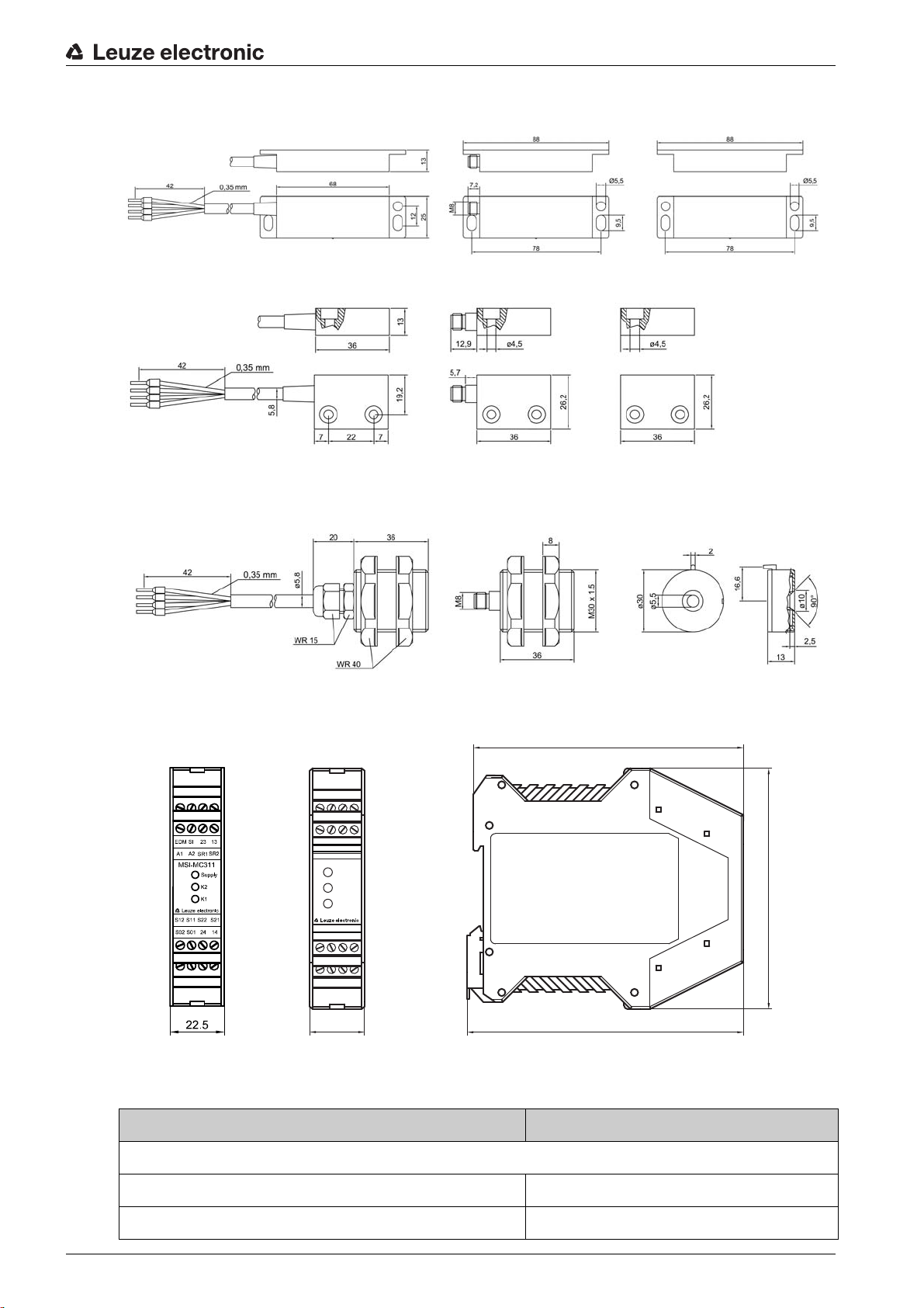
14 Dimensions and weights
22.5
99.0
113.6
111
24
S11
31
OUT
A2
A1
23
SR
13
A
S22
S33
S34
S12
32
14
MSI-MC310
Supply
K2
K1
Figure 14.1: Dimensions of MC388x sensor and actuator
Figure 14.2: Dimensions of MC336x sensor and actuator
Dimensions and weights
Figure 14.3: Dimensions of MC330x sensor and actuator
Figure 14.4: Dimensions of MSI-MC310/MSI-MC311 Safety Relay
Table 14.1: Weights
Description Weight (g)
Magnetically Coded Sensors of the MC388 series
MC388-S1C2-A 200
MC388-S1C5-A 345
Leuze electronic MC3x 53
Page 54
Description Weight (g)
MC388-S1C10-A 583
MC388-S1R2-A 190
MC388-S1R5-A 320
MC388-S1R10-A 531
MC388-S1M8-A 107
MC388-S1C02M12-A 134
MC388-S2C2-A 208
MC388-S2C5-A 353
MC388-S2M8-A 117
MC388-S2-C02M12-A 142
MC388 accessories
Dimensions and weights
MC388-S1-A 46
MC388-S2-A 47
MC388-SP-8 46
Magnetically Coded Sensors of the MC336 series
MC336-S1C2-A 160
MC336-S1C5-A 305
MC336-S1C10-A 540
MC336-S1R2-A 150
MC336-S1R5-A 280
MC336-S1R10-A 488
MC336-S1M8-A 67
MC366-S1-C02M12-A 94
MC336-S2C2-A 172
MC336-S2C5-A 317
MC336-S2M8-A 82
MC336-S2C02M12-A 106
MC336 accessories
MC336-S1-A 26
MC336-S2-A 25
MC336-SP-8 26
Magnetically Coded Sensors of the MC330 series
MC330-S1C2-A 188
MC330-S1C5-A 334
Leuze electronic MC3x 54
Page 55

Description Weight (g)
MC330-S1C10-A 572
MC330-S1R2-A 178
MC330-S1R5-A 309
MC330-S1R10-A 520
MC330-S1M8-A 95
MC330-S1-C02M12-A 122
MC330-S2C2-A 200
MC330-S2C5-A 345
MC330-S2M8-A 110
MC330-S2-C02M12-A 134
MC330 accessories
Dimensions and weights
MC330-S1-A 21
MC330-S2-A 21
MSI-MC3x Safety Relays
MSI-MC310 220
MSI-MC311 203
Leuze electronic MC3x 55
Page 56
15 Ordering information and accessories
Ordering information and accessories
Order number
Magnetically Coded Sensors of the MC388 series
63001000 MC388-S1C2-A Sensor, 1NO/1NC Connection cable 2 m, PVC
63001001 MC388-S1C5-A Sensor, 1NO/1NC Connection cable 5 m, PVC
63001002 MC388-S1C10-A Sensor, 1NO/1NC Connection cable 10 m, PVC
63001003 MC388-S1R2-A Sensor, 1NO/1NC Connection cable 2 m, PUR
63001004 MC388-S1R5-A Sensor, 1NO/1NC Connection cable 5 m, PUR
63001005 MC388-S1R10-A Sensor, 1NO/1NC Connection cable 10 m, PUR
63001006 MC388-S1M8-A Sensor, 1NO/1NC M8 plug 4-pin
63001007 MC388-S1C02M12-A Sensor, 1NO/1NC Connection cable
63001020 MC388-S2C2-A Sensor, 2NO Connection cable 2 m, PVC
63001021 MC388-S2C5-A Sensor, 2NO Connection cable 5 m, PVC
63001026 MC388-S2M8-A Sensor, 2NO M8 plug 4-pin
Description Description Connection
0.2 m, PVC
with M12 plug
63001027 MC388-S2-C02M12-A Sensor, 2NO Connection cable
with M12 plug
MC388 accessories
63001150 MC388-S1-A Actuator
63001155 MC388-S2-A Actuator
63001153 MC388-SP-8 Spacer, 8 mm
Magnetically Coded Sensors of the MC336 series
63001050 MC336-S1C2-A Sensor, 1NO/1NC Connection cable 2 m, PVC
63001051 MC336-S1C5-A Sensor, 1NO/1NC Connection cable 5 m, PVC
63001052 MC336-S1C10-A Sensor, 1NO/1NC Connection cable 10 m, PVC
63001053 MC336-S1R2-A Sensor, 1NO/1NC Connection cable 2 m, PUR
63001054 MC336-S1R5-A Sensor, 1NO/1NC Connection cable 5 m, PUR
63001055 MC336-S1R10-A Sensor, 1NO/1NC Connection cable 10 m, PUR
63001056 MC336-S1M8-A Sensor, 1NO/1NC M8 plug 4-pin
63001057 MC366-S1-C02M12-A Sensor, 1NO/1NC Connection cable
with M12 plug
0.2 m, PVC
0.2 m, PVC
63001070 MC336-S2C2-A Sensor, 2NO Connection cable 2 m, PVC
63001071 MC336-S2C5-A Sensor, 2NO Connection cable 5 m, PVC
63001076 MC336-S2M8-A Sensor, 2NO M8 plug 4-pin
63001077 MC336-S2C02M12-A Sensor, 2NO Connection cable
with M12 plug
Leuze electronic MC3x 56
0.2 m, PVC
Page 57
Ordering information and accessories
Order num-
Description Description Connection
ber
MC336 accessories
63001151 MC336-S1-A Actuator
63001156 MC336-S2-A Actuator
63001154 MC336-SP-8 Spacer, 8 mm
Magnetically Coded Sensors of the MC330 series
63001100 MC330-S1C2-A Sensor, 1NO/1NC Connection cable 2 m, PVC
63001101 MC330-S1C5-A Sensor, 1NO/1NC Connection cable 5 m, PVC
63001102 MC330-S1C10-A Sensor, 1NO/1NC Connection cable 10 m, PVC
63001103 MC330-S1R2-A Sensor, 1NO/1NC Connection cable 2 m, PUR
63001104 MC330-S1R5-A Sensor, 1NO/1NC Connection cable 5 m, PUR
63001105 MC330-S1R10-A Sensor, 1NO/1NC Connection cable 10 m, PUR
63001106 MC330-S1M8-A Sensor, 1NO/1NC M8 plug 4-pin
63001107 MC330-S1-C02M12-A Sensor, 1NO/1NC Connection cable
0.2 m, PVC
with M12 plug
63001120 MC330-S2C2-A Sensor, 2NO Connection cable 2 m, PVC
63001121 MC330-S2C5-A Sensor, 2NO Connection cable 5 m, PVC
63001126 MC330-S2M8-A Sensor, 2NO M8 plug 4-pin
63001127 MC330-S2-C02M12-A Sensor, 2NO Connection cable
0.2 m, PVC
with M12 plug
MC330 accessories
63001152 MC330-S1-A Actuator
63001157 MC330-S2-A Actuator
MSI-MC3x Safety Relays
549941 MSI-MC310 Safety Relay
549942 MSI-MC311 Safety Relay
Leuze electronic MC3x 57
Page 58

16 EC Declaration of Conformity
EC Declaration of Conformity
Leuze electronic MC3x 58
 Loading...