

Page 1

MA 235i
Fieldbus Gateway – CANopen
en 04-2017/01 50120388
We reserve the right to
make technical changes
Original operating instructions
Page 2

© 2017
Leuze electronic GmbH + Co. KG
In der Braike 1
D-73277 Owen / Germany
Phone: +49 7021 573-0
Fax: +49 7021 573-199
http://www.leuze.com
info@leuze.com
Leuze electronic MA 235i
Page 3

Table of contents
1 General information . . . . . . . . . . . . . . . . . . . . . . . . . . . . . . . . . . . . 5
1.1 Explanation of symbols . . . . . . . . . . . . . . . . . . . . . . . . . . . . . . . . . . . . . . . . . . . . . . . . . . . 5
1.2 Declaration of Conformity . . . . . . . . . . . . . . . . . . . . . . . . . . . . . . . . . . . . . . . . . . . . . . . . . 5
1.3 Description of functions . . . . . . . . . . . . . . . . . . . . . . . . . . . . . . . . . . . . . . . . . . . . . . . . . . 6
1.4 Definition of terms . . . . . . . . . . . . . . . . . . . . . . . . . . . . . . . . . . . . . . . . . . . . . . . . . . . . . . . 7
2 Safety . . . . . . . . . . . . . . . . . . . . . . . . . . . . . . . . . . . . . . . . . . . . . . . 8
2.1 Intended use . . . . . . . . . . . . . . . . . . . . . . . . . . . . . . . . . . . . . . . . . . . . . . . . . . . . . . . . . . . 8
2.2 Foreseeable misuse. . . . . . . . . . . . . . . . . . . . . . . . . . . . . . . . . . . . . . . . . . . . . . . . . . . . . . 8
2.3 Competent persons . . . . . . . . . . . . . . . . . . . . . . . . . . . . . . . . . . . . . . . . . . . . . . . . . . . . . . 9
2.4 Disclaimer. . . . . . . . . . . . . . . . . . . . . . . . . . . . . . . . . . . . . . . . . . . . . . . . . . . . . . . . . . . . . . 9
3 Fast commissioning / operating principle . . . . . . . . . . . . . . . . . . . 10
3.1 Mounting . . . . . . . . . . . . . . . . . . . . . . . . . . . . . . . . . . . . . . . . . . . . . . . . . . . . . . . . . . . . . 10
3.2 Device arrangement and selection of the mounting location . . . . . . . . . . . . . . . . . . . . 10
3.3 Electrical connection . . . . . . . . . . . . . . . . . . . . . . . . . . . . . . . . . . . . . . . . . . . . . . . . . . . . 10
3.3.1 Connecting the Leuze device . . . . . . . . . . . . . . . . . . . . . . . . . . . . . . . . . . . . . . . . . . . . . . 11
3.3.2 Connecting the power supply and the bus cable . . . . . . . . . . . . . . . . . . . . . . . . . . . . . . . 13
3.4 Starting the device. . . . . . . . . . . . . . . . . . . . . . . . . . . . . . . . . . . . . . . . . . . . . . . . . . . . . . 13
3.5 MA 235i on the CANopen . . . . . . . . . . . . . . . . . . . . . . . . . . . . . . . . . . . . . . . . . . . . . . . . 13
4 Device description . . . . . . . . . . . . . . . . . . . . . . . . . . . . . . . . . . . . 14
4.1 General Information to the connector units . . . . . . . . . . . . . . . . . . . . . . . . . . . . . . . . . . 14
4.2 Characteristics of the connector units . . . . . . . . . . . . . . . . . . . . . . . . . . . . . . . . . . . . . . 14
4.3 Device construction. . . . . . . . . . . . . . . . . . . . . . . . . . . . . . . . . . . . . . . . . . . . . . . . . . . . . 15
4.4 Operating modes . . . . . . . . . . . . . . . . . . . . . . . . . . . . . . . . . . . . . . . . . . . . . . . . . . . . . . . 16
4.5 Fieldbus systems . . . . . . . . . . . . . . . . . . . . . . . . . . . . . . . . . . . . . . . . . . . . . . . . . . . . . . . 17
4.5.1 CANopen . . . . . . . . . . . . . . . . . . . . . . . . . . . . . . . . . . . . . . . . . . . . . . . . . . . . . . . . . . . . . 17
5 Specifications . . . . . . . . . . . . . . . . . . . . . . . . . . . . . . . . . . . . . . . . 21
5.1 General specifications . . . . . . . . . . . . . . . . . . . . . . . . . . . . . . . . . . . . . . . . . . . . . . . . . . . 21
5.2 Dimensioned drawings . . . . . . . . . . . . . . . . . . . . . . . . . . . . . . . . . . . . . . . . . . . . . . . . . . 22
5.3 Type overview . . . . . . . . . . . . . . . . . . . . . . . . . . . . . . . . . . . . . . . . . . . . . . . . . . . . . . . . . 23
6 Installation and mounting . . . . . . . . . . . . . . . . . . . . . . . . . . . . . . . 24
6.1 Storage, transportation . . . . . . . . . . . . . . . . . . . . . . . . . . . . . . . . . . . . . . . . . . . . . . . . . . 24
Leuze electronic MA 235i 1
Page 4

Table of contents
6.2 Mounting . . . . . . . . . . . . . . . . . . . . . . . . . . . . . . . . . . . . . . . . . . . . . . . . . . . . . . . . . . . . . . 25
6.3 Device arrangement . . . . . . . . . . . . . . . . . . . . . . . . . . . . . . . . . . . . . . . . . . . . . . . . . . . . . 26
6.3.1 Selecting a mounting location . . . . . . . . . . . . . . . . . . . . . . . . . . . . . . . . . . . . . . . . . . . . . . 26
6.4 Cleaning . . . . . . . . . . . . . . . . . . . . . . . . . . . . . . . . . . . . . . . . . . . . . . . . . . . . . . . . . . . . . . 26
7 Electrical connection . . . . . . . . . . . . . . . . . . . . . . . . . . . . . . . . . . 27
7.1 Safety notices for the electrical connection . . . . . . . . . . . . . . . . . . . . . . . . . . . . . . . . . . 27
7.2 Electrical connection . . . . . . . . . . . . . . . . . . . . . . . . . . . . . . . . . . . . . . . . . . . . . . . . . . . .28
7.2.1 PWR IN – voltage supply / switching input/output . . . . . . . . . . . . . . . . . . . . . . . . . . . . . . 28
7.2.2 PWR OUT switching input/output . . . . . . . . . . . . . . . . . . . . . . . . . . . . . . . . . . . . . . . . . . . 30
7.3 BUS IN . . . . . . . . . . . . . . . . . . . . . . . . . . . . . . . . . . . . . . . . . . . . . . . . . . . . . . . . . . . . . . . . 30
7.4 BUS OUT . . . . . . . . . . . . . . . . . . . . . . . . . . . . . . . . . . . . . . . . . . . . . . . . . . . . . . . . . . . . . . 31
7.4.1 Termination of the CANopen bus . . . . . . . . . . . . . . . . . . . . . . . . . . . . . . . . . . . . . . . . . . . 31
7.5 Device interfaces . . . . . . . . . . . . . . . . . . . . . . . . . . . . . . . . . . . . . . . . . . . . . . . . . . . . . . . 32
7.5.1 RS 232 device interface (accessible after opening the device, internal) . . . . . . . . . . . . . . 32
7.5.2 Service interface (internal) . . . . . . . . . . . . . . . . . . . . . . . . . . . . . . . . . . . . . . . . . . . . . . . . . 33
8 Status displays and operational controls . . . . . . . . . . . . . . . . . . . . 34
8.1 LED status indicators . . . . . . . . . . . . . . . . . . . . . . . . . . . . . . . . . . . . . . . . . . . . . . . . . . . . 34
8.1.1 LED indicators on the circuit board . . . . . . . . . . . . . . . . . . . . . . . . . . . . . . . . . . . . . . . . . . 34
8.1.2 LED indicators on the housing . . . . . . . . . . . . . . . . . . . . . . . . . . . . . . . . . . . . . . . . . . . . 35
8.2 Internal interfaces and operational controls . . . . . . . . . . . . . . . . . . . . . . . . . . . . . . . . . .36
8.2.1 Overview of operational controls of the. . . . . . . . . . . . . . . . . . . . . . . . . . . . . . . . . . . . . . . 36
8.2.2 Connector X30 … connectors . . . . . . . . . . . . . . . . . . . . . . . . . . . . . . . . . . . . . . . . . . . . . . 38
8.2.3 RS 232 service interface – X33 . . . . . . . . . . . . . . . . . . . . . . . . . . . . . . . . . . . . . . . . . . . . . 38
8.2.4 S10 service switch. . . . . . . . . . . . . . . . . . . . . . . . . . . . . . . . . . . . . . . . . . . . . . . . . . . . . . . 38
8.2.5 Rotary switch S4 for device selection . . . . . . . . . . . . . . . . . . . . . . . . . . . . . . . . . . . . . . . . 39
8.2.6 Switch for address selection in the fieldbus . . . . . . . . . . . . . . . . . . . . . . . . . . . . . . . . . . . 40
8.2.7 Switch for setting the baud rate . . . . . . . . . . . . . . . . . . . . . . . . . . . . . . . . . . . . . . . . . . . . 40
9 Configuration . . . . . . . . . . . . . . . . . . . . . . . . . . . . . . . . . . . . . . . . 41
9.1 Connecting the service interface . . . . . . . . . . . . . . . . . . . . . . . . . . . . . . . . . . . . . . . . . . . 41
9.2 Reading out information in Service mode . . . . . . . . . . . . . . . . . . . . . . . . . . . . . . . . . . . . 41
10 Telegram . . . . . . . . . . . . . . . . . . . . . . . . . . . . . . . . . . . . . . . . . . . . 44
10.1 Structure of the fieldbus telegram . . . . . . . . . . . . . . . . . . . . . . . . . . . . . . . . . . . . . . . . . . 44
10.2 Description of the input bytes (status bytes). . . . . . . . . . . . . . . . . . . . . . . . . . . . . . . . . . 45
10.2.1 Structure and meaning of the input bytes (status bytes). . . . . . . . . . . . . . . . . . . . . . . . . . 45
10.2.2 Detailed description of the bits (input byte 0) . . . . . . . . . . . . . . . . . . . . . . . . . . . . . . . . . . 46
2 MA 235i Leuze electronic
Page 5

Table of contents
10.2.3 Detailed description of the bits (input byte 1) . . . . . . . . . . . . . . . . . . . . . . . . . . . . . . . . . . 48
10.3 Description of the output bytes (control bytes) . . . . . . . . . . . . . . . . . . . . . . . . . . . . . . . 48
10.3.1 Structure and meaning of the output bytes (control bytes) . . . . . . . . . . . . . . . . . . . . . . . 48
10.3.2 Detailed description of the bits (output byte 0). . . . . . . . . . . . . . . . . . . . . . . . . . . . . . . . . 49
10.3.3 Detailed description of the bits (output byte 1). . . . . . . . . . . . . . . . . . . . . . . . . . . . . . . . . 50
10.4 RESET function / deleting memory . . . . . . . . . . . . . . . . . . . . . . . . . . . . . . . . . . . . . . . . . 51
11 Modes. . . . . . . . . . . . . . . . . . . . . . . . . . . . . . . . . . . . . . . . . . . . . . 52
11.1 Functionality of the data exchange. . . . . . . . . . . . . . . . . . . . . . . . . . . . . . . . . . . . . . . . . 52
11.1.1 Reading slave data in Collective mode (gateway -> PLC) . . . . . . . . . . . . . . . . . . . . . . . . 53
11.1.2 Writing slave data in Collective mode (PLC -> gateway) . . . . . . . . . . . . . . . . . . . . . . . . . 53
11.1.3 Command mode . . . . . . . . . . . . . . . . . . . . . . . . . . . . . . . . . . . . . . . . . . . . . . . . . . . . . . . . 56
12 Commissioning and configuration. . . . . . . . . . . . . . . . . . . . . . . . . 58
12.1 Measures to be performed prior to the initial commissioning. . . . . . . . . . . . . . . . . . . . 58
12.1.1 Connecting the power supply and the bus cable . . . . . . . . . . . . . . . . . . . . . . . . . . . . . . . 60
12.2 Starting the device. . . . . . . . . . . . . . . . . . . . . . . . . . . . . . . . . . . . . . . . . . . . . . . . . . . . . . 60
12.3 MA 235i in the CANopen system . . . . . . . . . . . . . . . . . . . . . . . . . . . . . . . . . . . . . . . . . . 61
12.4 Starting the MA 235i in the CANopen system . . . . . . . . . . . . . . . . . . . . . . . . . . . . . . . . 62
12.4.1 Device profile . . . . . . . . . . . . . . . . . . . . . . . . . . . . . . . . . . . . . . . . . . . . . . . . . . . . . . . . . . 62
12.4.2 Object directories . . . . . . . . . . . . . . . . . . . . . . . . . . . . . . . . . . . . . . . . . . . . . . . . . . . . . . . 63
12.4.3 SDOs and PDOs . . . . . . . . . . . . . . . . . . . . . . . . . . . . . . . . . . . . . . . . . . . . . . . . . . . . . . . . 63
12.4.4 SDOs. . . . . . . . . . . . . . . . . . . . . . . . . . . . . . . . . . . . . . . . . . . . . . . . . . . . . . . . . . . . . . . . . 63
12.4.5 PDOs. . . . . . . . . . . . . . . . . . . . . . . . . . . . . . . . . . . . . . . . . . . . . . . . . . . . . . . . . . . . . . . . . 64
12.4.6 Object index . . . . . . . . . . . . . . . . . . . . . . . . . . . . . . . . . . . . . . . . . . . . . . . . . . . . . . . . . . . 65
12.5 Setting the read parameters on the Leuze device . . . . . . . . . . . . . . . . . . . . . . . . . . . . . 69
12.5.1 Specific feature for the use of hand-held scanners
(bar code and 2D devices, combi devices with RFID) . . . . . . . . . . . . . . . . . . . . . . . . . . . 70
12.5.2 Specific features in the operation of an RFM/RFI. . . . . . . . . . . . . . . . . . . . . . . . . . . . . . . 71
13 Diagnostics and troubleshooting . . . . . . . . . . . . . . . . . . . . . . . . . 72
13.1 General causes of errors . . . . . . . . . . . . . . . . . . . . . . . . . . . . . . . . . . . . . . . . . . . . . . . . . 72
13.2 Interface errors. . . . . . . . . . . . . . . . . . . . . . . . . . . . . . . . . . . . . . . . . . . . . . . . . . . . . . . . . 73
14 Type overview and accessories . . . . . . . . . . . . . . . . . . . . . . . . . . 74
14.1 Part number code . . . . . . . . . . . . . . . . . . . . . . . . . . . . . . . . . . . . . . . . . . . . . . . . . . . . . . 74
14.2 Type overview . . . . . . . . . . . . . . . . . . . . . . . . . . . . . . . . . . . . . . . . . . . . . . . . . . . . . . . . . 74
14.3 Accessory terminating resistor . . . . . . . . . . . . . . . . . . . . . . . . . . . . . . . . . . . . . . . . . . . . 74
14.4 Accessory connectors . . . . . . . . . . . . . . . . . . . . . . . . . . . . . . . . . . . . . . . . . . . . . . . . . . . 74
Leuze electronic MA 235i 3
Page 6

Table of contents
14.5 Accessory ready-made cables for voltage supply . . . . . . . . . . . . . . . . . . . . . . . . . . . . . 75
14.5.1 Contact assignment of PWR connection cable . . . . . . . . . . . . . . . . . . . . . . . . . . . . . . . . . 75
14.5.2 Specifications of the cables for voltage supply. . . . . . . . . . . . . . . . . . . . . . . . . . . . . . . . .75
14.5.3 Order codes of the cables for voltage supply . . . . . . . . . . . . . . . . . . . . . . . . . . . . . . . . . . 76
14.6 Accessory ready-made cables for bus connection . . . . . . . . . . . . . . . . . . . . . . . . . . . . 76
14.6.1 General information . . . . . . . . . . . . . . . . . . . . . . . . . . . . . . . . . . . . . . . . . . . . . . . . . . . . . . 76
14.6.2 Contact assignment of M12-CANopen connection cable KB DN…. . . . . . . . . . . . . . . . . 76
14.6.3 Specifications of M12-CANopen connection cable KB DN…. . . . . . . . . . . . . . . . . . . . . . 77
14.6.4 Order codes of M12-CANopen connection cable KB DN… . . . . . . . . . . . . . . . . . . . . . . . 77
14.7 Accessory ready-made cables for connecting Leuze Ident devices . . . . . . . . . . . . . . . 78
14.7.1 Order codes for the device connection cables . . . . . . . . . . . . . . . . . . . . . . . . . . . . . . . . . 78
14.7.2 Contact assignment for the device connection cables . . . . . . . . . . . . . . . . . . . . . . . . . . . 78
15 Maintenance . . . . . . . . . . . . . . . . . . . . . . . . . . . . . . . . . . . . . . . . . 79
15.1 General maintenance information . . . . . . . . . . . . . . . . . . . . . . . . . . . . . . . . . . . . . . . . . . 79
15.2 Repairs, servicing . . . . . . . . . . . . . . . . . . . . . . . . . . . . . . . . . . . . . . . . . . . . . . . . . . . . . . . 79
15.3 Disassembling, packing, disposing . . . . . . . . . . . . . . . . . . . . . . . . . . . . . . . . . . . . . . . . . 79
16 Specifications for Leuze end devices . . . . . . . . . . . . . . . . . . . . . . 80
16.1 Standard setting, KONTURflex (S4 switch position 0) . . . . . . . . . . . . . . . . . . . . . . . . . . 80
16.2 Bar code reader BCL 8 (S4 switch position 1) . . . . . . . . . . . . . . . . . . . . . . . . . . . . . . . . 82
16.3 Bar code reader BCL 22 (S4 switch position 2) . . . . . . . . . . . . . . . . . . . . . . . . . . . . . . . 83
16.4 Bar code reader BCL 300i, BCL 500i, BCL 600i (S4 switch position 4) . . . . . . . . . . . . . 84
16.5 Bar code reader BCL 90, BCL 900i (S4 switch position 5) . . . . . . . . . . . . . . . . . . . . . . . 85
16.6 LSIS 122, LSIS 222 (S4 switch position 6) . . . . . . . . . . . . . . . . . . . . . . . . . . . . . . . . . . . . 86
16.7 LSIS 4x2i, DCR 202i (S4 switch position 7) . . . . . . . . . . . . . . . . . . . . . . . . . . . . . . . . . . . 87
16.8 Hand-held scanner (S4 switch position 8) . . . . . . . . . . . . . . . . . . . . . . . . . . . . . . . . . . . . 88
16.9 RFI, RFM, RFU RFID readers (S4 switch position 9) . . . . . . . . . . . . . . . . . . . . . . . . . . . . 89
16.10 BPS 8 bar code positioning system (S4 switch position A) . . . . . . . . . . . . . . . . . . . . . . 90
16.11 BPS 300i bar code positioning system, ODSL xx optical distance sensors
with RS 232 interface (S4 switch position B). . . . . . . . . . . . . . . . . . . . . . . . . . . . . . . . . .91
16.12 Modular interfacing unit MA 3x (S4 switch position C) . . . . . . . . . . . . . . . . . . . . . . . . . . 93
16.13 Resetting the parameters (S4 switch position F) . . . . . . . . . . . . . . . . . . . . . . . . . . . . . . 94
17 Appendix . . . . . . . . . . . . . . . . . . . . . . . . . . . . . . . . . . . . . . . . . . . . 95
17.1 ASCII Table . . . . . . . . . . . . . . . . . . . . . . . . . . . . . . . . . . . . . . . . . . . . . . . . . . . . . . . . . . . . 95
4 MA 235i Leuze electronic
Page 7

1 General information
1.1 Explanation of symbols
The symbols used in this operating manual are explained below.
Attention!
This symbol precedes text messages which must strictly be observed. Failure to comply with
this information results in injuries to persons or damage to the equipment.
Notice!
This symbol indicates text passages containing important information.
1.2 Declaration of Conformity
The MA 235i modular interfacing units have been designed and manufactured in accordance with applicable European directives and standards.
Notice!
The Declaration of Conformity for these devices can be requested from the manufacturer.
General information
The manufacturer of the product, Leuze electronic GmbH + Co. KG in D-73277 Owen,
possesses a certified quality assurance system in accordance with ISO 9001.
The modular interfacing unit is "UL LISTED" in accordance with American and Canadian
safety standards and fulfills requirements of Underwriter Laboratories Inc. (UL).
Leuze electronic MA 235i 5
TNT 35/7-24V
Page 8

General information
1.3 Description of functions
The MA 235i modular interfacing unit is used to connect Leuze devices directly to the
fieldbus.
Bar code reader: BCL 8, 22, 300i, 500i, 600i, 90, 900i
2D-code reader: LSIS 122, LSIS 222, LSIS 4x2i, DCR 200i
Hand-held scanner ITxxxx, HFU/HFM
RFID read-write devices: RFM 12, 32, 62 & RFI 32, RFU 100, RFU 200
Bar code positioning system: BPS 8, BPS 300
Optical distance sensors: ODSL 9, ODSL 30, ODSL 96B
Measuring light curtain: KONTURflex to Quattro-RSX/M12
multiNet master connection box: MA 3x
Additional RS 232 devices: Scales, third-party devices
This is accomplished by transmitting the data from the DEV via an RS 232 (V.24) interface
to the MA 235i where a module converts it into the CANopen format. The data format on
the RS 232 interface corresponds to the Leuze standard data format (9600bd, 8N1 and STX,
data, CR, LF).
The corresponding Leuze devices are selected using a rotary code switch on the circuit
board of the connector unit. Many additional RS 232 devices can be connected through a
universal position.
Leuze electronic can only provide support for the devices offered in the product range.
6MA235i Leuze electronic
Page 9

1.4 Definition of terms
For better understanding of the explanations provided in this document, a definition of terms
follows below:
General information
• Bit designation:
The 1st bit or byte begins with count number "0" and means bit/byte 2
• Data length:
Size of a valid, continuous data packet in bytes.
• EDS file (electronic data sheet):
Description of the device for the control.
• Consistent:
Data which belongs together with regard to content and which must not be separated
is referred to as consistent data. When identifying objects, it must be ensured that
the data is transmitted completely and in the correct order, otherwise the result is
falsified.
• Leuze device (DEV):
Leuze devices, e.g., bar code readers, RFID readers, VisionReader…
• Online command:
These commands refer to the respective, connected ident device and may be different depending on the device. These commands are not interpreted by the MA 235i,
but are instead transmitted transparently (see description of Ident device).
• CR:
Cross reference.
• Perspective of I/O data in the description:
Output data is data which is sent by the control to the MA. Input data is data which
is sent by the MA to the control.
• Tog g le b its :
Status toggle bit
Each change of state indicates that an action was performed, e.g., bit ND (new data):
each change of state indicates that new received data was transmitted to the PLC.
Control toggle bit
An action is performed on each change of state, e.g., bit SDO: on each change of
state, the registered data is sent by the PLC to the MA 235i.
0
.
TNT 35/7-24V
Leuze electronic MA 235i 7
Page 10

Safety
2 Safety
This device was developed, manufactured and tested in line with the applicable safety standards. It corresponds to the state of the art.
2.1 Intended use
The MA 235i modular interfacing unit is used for connecting Leuze devices such as bar code
or 2D-code readers, hand-held scanners, RFID read-write devices, etc. directly to the
fieldbus.
CAUTION
Observe intended use!
Only operate the device in accordance with its intended use. The protection of per-
sonnel and the device cannot be guaranteed if the device is operated in a manner not
complying with its intended use.
Leuze electronic GmbH + Co. KG is not liable for damages caused by improper use.
Read the technical description before commissioning the device. Knowledge of this
technical description is an element of proper use.
NOTICE
Comply with conditions and regulations!
Observe the locally applicable legal regulations and the rules of the employer's liability
insurance association.
Attention
For UL applications, use is permitted exclusively in Class 2 circuits according to NEC
(National Electric Code).
2.2 Foreseeable misuse
Any use other than that defined under "Intended use" or which goes beyond that use is
considered improper use.
In particular, use of the device is not permitted in the following cases:
• Rooms with explosive atmospheres
• As stand-alone safety component in accordance with the machinery directive
• For medicinal purposes
1) Use as safety-related component within the safety function is possible, if the component combination is designed correspondingly by the machine manufacturer.
8MA235i Leuze electronic
1)
Page 11

NOTICE
Do not modify or otherwise interfere with the device.
Do not carry out modifications or otherwise interfere with the device.
The device must not be tampered with and must not be changed in any way.
The device must not be opened. There are no user-serviceable parts inside.
Repairs must only be performed by Leuze electronic GmbH + Co. KG.
2.3 Competent persons
Connection, mounting, commissioning and adjustment of the device must only be carried
out by competent persons.
Prerequisites for competent persons:
• They have a suitable technical education.
• They are familiar with the rules and regulations for occupational safety and safety at
work.
• They are familiar with the technical description of the device.
• They have been instructed by the responsible person on the mounting and operation
of the device.
Certified electricians
Electrical work must be carried out by a certified electrician.
Due to their technical training, knowledge and experience as well as their familiarity with
relevant standards and regulations, certified electricians are able to perform work on electrical systems and independently detect possible dangers.
In Germany, certified electricians must fulfill the requirements of accident-prevention regulations BGV A3 (e.g. electrician foreman). In other countries, there are respective regulations that must be observed.
Safety
2.4 Disclaimer
Leuze electronic GmbH + Co. KG is not liable in the following cases:
• The device is not being used properly.
• Reasonably foreseeable misuse is not taken into account.
• Mounting and electrical connection are not properly performed.
• Changes (e.g., constructional) are made to the device.
Leuze electronic MA 235i 9
TNT 35/7-24V
Page 12

Fast commissioning / operating principle
PWR OUT
VOUT
123
4
SWIO_2
GND
FE
5
PWR IN
SWIO_1
SWIO_2
321
4
5
GND VIN
FE
LEUZE Device
HOST / BUS IN
SWIO_1
V+
CAN_H
143
2
5
DRAIN
V-
CAN_L
1
2
3
4
5
BUS OUT
V+
CAN_H
DRAINV-
CAN_L
M12 connector
(A-coded)
M12 socket
(A-coded)
M12 connector
(A-coded)
M12 socket
(A-coded)
3 Fast commissioning / operating principle
Notice!
Below you will find a short description for the initial commissioning of the CANopen
gateway MA 235i. Detailed explanations for the listed points can be found throughout the
handbook.
3.1 Mounting
The gateway mounting plate MA 235i can be mounted in two different ways:
• using four threaded holes (M6) or
• using two M8x6 screws on the two lateral grooves.
3.2 Device arrangement and selection of the mounting location
Ideally, the MA 235i should be mounted so that it is easily accessible near the Ident device
in order to ensure good operability, e.g., for configuring the connected device.
Detailed information can be found in chapter 6.3.1.
3.3 Electrical connection
The devices from the MA 2xxi family feature four M12 connectors/sockets which are coded
differently depending on the interface.
The voltage supply (PWR IN) as well as the switching inputs/outputs (PWR OUT or PWR IN)
are connected there. The number and function of the switching inputs/outputs is dependent
on the connected end device.
An internal RS 232 interface is used for connecting the respective Leuze device. Another
internal RS 232 interface functions as a service interface for configuring the connected
device via a serial null modem cable.
Figure 3.1: MA 235i connections
Detailed information can be found in chapter 7.
10 MA 235i Leuze electronic
Page 13

3.3.1 Connecting the Leuze device
OnesTens
To connect the Leuze device to the internal RS 232 device interface, open the housing
of the MA 235i and lead the corresponding device cable (see chapter 14.7) through the
middle threaded opening.
Connect the cable to the internal device interface (X30, X31 or X32, see chapter 7.5.1).
Use rotary switch S4 (see chapter 8.2.5) to select the connected device.
Now screw the PG cable gland into the threaded opening to provide strain relief and
ensure protection class IP 65.
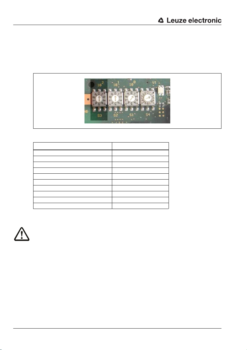
Set CANopen device address
By setting the CANopen address, the MA 235i is assigned its respective station number.
Each network device is thereby automatically informed that it is a slave on the CANopen
with its specific address and that it is initialized and queried by the PLC.
The CANopen permits an address range from 0 to 127, the MA a range from 0 to 99. Other
addresses must not be used for data communication.
Set the station address of the gateway using the two rotary switches S1 and S2 (ones
and tens places).
Fast commissioning / operating principle
Figure 3.2: Rotary switch for setting the address
Leuze electronic MA 235i 11
TNT 35/7-24V
Page 14
Fast commissioning / operating principle
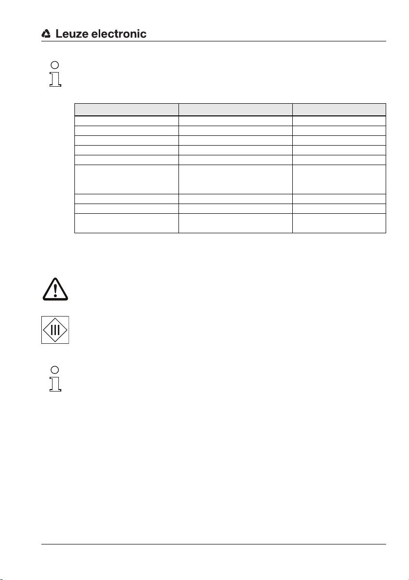
Set CANopen baud rate on the MA
The CANopen baud rate is defined for the entire network in the planning tool/control. The
baud rate is set on the MA 235i via the baud rate selector switch. Only if the baud rates are
the same is communication with the MA 235i possible.
Set the baud rate of the gateway via the S3 rotary switch to the value defined in the control.
Figure 3.3: Rotary switch for setting baud rate
Switch position Baud rate [kBd]
0 auto
1 10
2 20
3 50
4 100
5 125
6 250
7 500
8 800
9 1000
Finally, close the housing of the MA 235i.
Attention!
Only then may the supply voltage be applied.
Upon startup of the MA 235i, the device selection switch is queried and the gateway automatically sets itself to the Leuze device.
Connecting functional earth FE
Ensure that the functional earth (FE) is connected correctly.
Unimpaired operation is only guaranteed when the functional earth is connected properly.
All electrical disturbances (EMC couplings) are discharged via the functional earth connection.
12 MA 235i Leuze electronic
Page 15

Fast commissioning / operating principle
3.3.2 Connecting the power supply and the bus cable
Ideally, use the ready-made cables listed in chapter 14.5.3 to connect the gateway to the
power supply via the PWR IN connection.
The ready-made cables listed in chapter 14.6.4 are preferred for connecting the gateway
to the fieldbus via the HOST / BUS IN connection.
If applicable, use the BUS OUT connection if you would like to construct a network with
linear topology.
3.4 Starting the device
Apply the supply voltage +18 … 30VDC (typ. +24VDC); the MA 235i starts up.
The PWR LED displays that it is ready for operation.
3.5 MA 235i on the CANopen
Install the EDS file corresponding to the MA 235i in your planning tool/the control.
Notice!
You can find the EDS file at: www.leuze.com
The MA 235i is configured in the planning tool/control by means of the EDS file. The MA 235i
is assigned an address in the planning tool, which then has to be set in the MA 235i via the
S1 and S2 address switches. Only if the addresses are the same between the MA 235i and
the control can communication be established.
After all parameters have been set in the planning tool/control, the download to the MA 235i
takes place. The set parameters are now stored on the MA 235i.
Afterwards, all MA 235i parameters should be stored via upload in the control. This aids in
retaining the parameters during device exchanges, as they a re now also stored centrally in
the control.
The CANopen baud rate is defined for the entire network in the planning tool/control. The
baud rate is set on the MA 235i via the S3 baud rate selector switch.
Only if the baud rates are the same is communication with the MA 235i possible.
Detailed information can be found in chapter 12.
Leuze electronic MA 235i 13
TNT 35/7-24V
Page 16

Device description
4 Device description
4.1 General Information to the connector units
The modular interfacing unit of the MA 2xxi family is a versatile gateway for integrating Leuze
RS 232 devices (e.g., BCL 22 bar code readers, RFID devices, RFM 32, …) into the respective fieldbus. The MA 2xxi gateways are intended for use in industrial environments with a
high protection class. Various device versions are available for the conventional fieldbuses.
With a stored parameter structure for the connectable RS 232 devices, commissioning
could hardly be simpler.
4.2 Characteristics of the connector units
A special characteristic of the MA 235i device family are three function modes:
1. Transparent mode
In this function mode, the MA 235i functions as a pure gateway with automatic communication from and to the PLC. Absolutely no special programming by the user is
necessary for this purpose. The data is not buffered or stored temporarily, however.
Instead, it is "passed on".
The programmer must make certain to retrieve the data from the input memory of the
PLC at the right time, as it is otherwise overwritten by new data.
2. Collective mode
In this operating mode, data and telegram parts are temporarily stored in the memory
(buffer) of the MA and sent to the RS 232 interface or to the PLC in a telegram by means
of bit activation. In this mode, however, all communication control must be programmed on the PLC.
This function mode is helpful, for example, for very long telegrams or when one or
more codes with long code lengths are read.
3. Command mode
With this special operating mode, it is possible to use the first bytes of the data range
to transmit predefined commands to the connected device by means of bit activation.
For this purpose, device-dependent commands (so-called online commands) are predefined via the device selection switch, see chapter 16 "Specifications for Leuze end
devices".
14 MA 235i Leuze electronic
Page 17

4.3 Device construction
Fieldbus
Fieldbus
MA 235i
Leuze
device
Either
network or other devices
with RS 232
RS 232
(V.24)
The MA 235i modular interfacing unit is used for interconnecting Leuze devices, such as
the BCL 8, BCL 22, etc., directly to the fieldbus. This is accomplished by transmitting the
data from the Leuze device via an RS 232 (V.24) interface to the MA 235i where a module
converts it into the fieldbus format. The data format of the RS 232 interface corresponds to
the standard Leuze data format.
Device description
Figure 4.1: Connection of a Leuze device (BCL, RFI, RFM, …) to the fieldbus
The cable of the respective Leuze device is guided through cable bushings with PG cable
glands into the MA 235i and connected there with the PCB connectors.
The MA 235i is intended as a gateway for any RS 232 devices, e.g., BCL 300i, hand-held
scanners, scales or for coupling a multiNet network.
The RS 232 cables are internally connectable using JST plug connectors. The cable can be
connected to the device using a stable PG cable gland which provide strain relief and protection against contamination.
With the help of adapter cables with Sub-D 9 or open cable end, other RS 232 devices can
also be connected.
Leuze electronic MA 235i 15
TNT 35/7-24V
Page 18

Device description
4.4 Operating modes
For fast commissioning, the MA 235i offers an additional operating mode, the "Service
mode", in addition to the "Standard mode". In this operating mode, the Leuze device can,
for example, be configured on the MA 235i and the network settings of the MA can be
displayed. To do this, you need a PC/laptop with a suitable terminal program, as BCL-Config
from Leuze or similar.
Service switch
Select between "operation" and "service" modes with the service switch. You have the
following options:
Pos. RUN:
Operation
The Leuze device is connected to the fieldbus and communicates with the PLC.
Pos. DEV:
Service Leuze device
The connection between the Leuze device and the fieldbus is interrupted. With this
switch position, you can communicate directly with the Leuze device at the fieldbus
gateway via RS 232. You can send online commands via the service interface, configure the Leuze device using the corresponding BCL- BPS-, …-Config configuration
software and have the read data of the Leuze device output.
Pos. MA:
Service fieldbus gateway
With this switch setting, your PC/terminal is connected with the fieldbus gateway.In
doing so, the current setting values of the MA (e.g. address, RS 232 parameters) can
be called up via a command.
Figure 4.2: Service-switch switch positions
Notice!
If the service switch is on one of the service settings, the CAN LED flashes on the front side
of the device, see chapter 8.1.2 "LED indicators on the housing".
Furthermore, on the control, the SMA service bit of the status bytes signals that the MA is
in service mode.
16 MA 235i Leuze electronic
Page 19

Service interface
5 GND
3 TxD
2 RxD
GND 5
TxD 3
RxD 2
1
1
PC/terminal
COM interface
MA 235i
Service interface
Terminator
Trunk Line
Tap
Terminator
Drop
Line
PLC
The service interface can be accessed once the MA 235i housing cover has been removed
and features a 9-pin Sub-D connector (male). A crossed RS 232 connection cable is required
to make the RxD, TxD and GND connections.
Figure 4.3: Connecting the service interface to a PC/terminal
Attention!
For the service PC to function, the RS 232 parameters must be the same as those of the
MA. The Leuze standard setting of the interface is 9600bd, 8N1 and STX, data, CR, LF.
4.5 Fieldbus systems
Various product variants of the MA 2xxi series are available for connecting to different
fieldbus systems such as PROFIBUS DP, PROFINET-IO, DeviceNet, CANopen and Ethernet
or EtherCAT.
Device description
4.5.1 CANopen
General information on CANopen
Figure 4.4: Bus topology
Leuze electronic MA 235i 17
TNT 35/7-24V
Page 20

Device description
The CAN bus is a serial 2-wire bus system to which all participants are connected in parallel (i.e., using short stub cables). To avoid reflections, the bus must be terminated with a
terminating resistor of 120ohm at each end of the trunk line. Terminating resistors are also
required for very short trunk line cable lengths.
If the MA 235i is the last participant in the trunk line, the trunk line can be terminated via
the M12 bus OUT connection. For this purpose, Leuze electronic offers an M12 terminating resistor, see chapter 14 "Type overview and accessories".
Bus line (trunk line)
For CAN, the maximum cable length of the trunk line is predominantly limited by the signal
propagation time. The multi-master bus-access process (arbitration) requires that the signals are present virtually simultaneously at all nodes/participants. Therefore, the cable
length of the trunk cable must be adapted to the baud rate.
Baud rate Bus length
1Mbit/s < 20m
800kbit/s < 50m
500kbit/s < 100m
250kbit/s < 250m
125kbit/s < 500m
50kbit/s < 1000m
20kbit/s < 2500m
Stub cables (drop lines)
If possible, stub cables should be avoided because they cause signal reflections as a matter of principle. Generally, the reflections caused by stub cables are not critical, however, if
the following stub cable lengths are not exceeded.
Baud rate Length of stub cables Total length of all stub cables
1Mbit/s <1m < 5m
800kbit/s < 1m < 25m
500kbit/s < 1m < 25m
250kbit/s <10m <50m
125kbit/s < 20m < 100m
50kbit/s < 50m < 250 m
20kbit/s < 50m < 250 m
Attention!
Stub cables must not be fitted with terminating resistors. If the MA 235i is integrated into a
stub cable, the M12 bus OUT connection must not be terminated.
18 MA 235i Leuze electronic
Page 21

Device description
Terminator
Trunk Line
Tap Terminator
Drop
Line
Tap Tap
Figure 4.5: Prohibited networking within a stub cable
Attention!
MA 235i should not be networked with each other within a stub cable. The max. permissible
cable length of a stub cable must not be exceeded. Taps and multi-taps permit a wide range
of topologies.
Leuze electronic MA 235i 19
TNT 35/7-24V
Page 22

Device description
Address assignment
Notice!
The participant-specific address for CANopen is also called the Node ID. Throughout this
handbook, the term "address" is used, which is identical to "Node ID".
Each participant connected to CANopen is assigned its own address (Node ID). Up to
127 participants can be connected to one network. The addresses of the MA range from
1 to 99. The address 0 is usually reserved for the CANopen master.
Notice
The "Layer Setting Services (LSS)" function is not supported by the MA 235i. For this reason,
the address must be set manually. See "Switch for address selection in the fieldbus" on
page 40.
Baud rate setting
The MA 235i supports the following baud rates:
1Mbit/s
800kbit/s
500kbit/s
250kbit/s
125kbit/s
100kbit/s
50kbit/s
20kbit/s
10kbit/s
The default setting of the gateway is "auto".
Notice
The "Layer Setting Services (LSS)" function is not supported by the MA 235i. The baud rate
must be set manually. See "Switch for setting the baud rate" on page 40.
20 MA 235i Leuze electronic
Page 23

5 Specifications
5.1 General specifications
Electrical data
Interface type 1 CANopen, integrated switch,
Interface type 2 RS 232
Service interface RS 232, 9-pin Sub-D connector, Leuze standard
data format Data bit: 8, parity: None, stop bit: 1
Switching input/output 1 switching input/1 switching output
Operating voltage 18 … 30VDC (PELV, Class 2)
Power consumption Max. 5VA (without DEV, current consumption max.
Max stress on the connector
(PWR IN/OUT)
Hand-held scanner operating voltage4.75 … 5.25V DC / max. 1A
Indicators
CAN LED green Bus state ok
PWR LED green Power
Mechanical data
Protection class IP 65 (with screwed-on M12 and connected Leuze
Weight 700 g
Dimensions (Hx WxD) 130 x 90 x 41mm / with plate: 180 x 108 x 41mm
Housing Diecast aluminum
Connection 2 x M12: BUS IN / BUS OUT CANopen
Environmental data
Operating temperature range 0°C … +55°C
Storage temperature range -20°C … +60°C
Air humidity Max. 90% rel. humidity, non-condensing
Vibration IEC 60068-2-6, test FC
Specifications
BUS: 1x M12 connector (A-coded),
1x M12 socket (A-coded)
PWR/IO: 1x M12 connector (A-coded),
device-dependent voltage
300mA)
3A
red Bus error
red Collection error
device)
1 connector: RS 232
1 x M12: Power IN/GND and switching input/output
1 x M12: Power OUT/GND and switching input/output
1x M12 socket (A-coded)
1)
TNT 35/7-24V
Leuze electronic MA 235i 21
Page 24

Specifications
Shock IEC 60068-2-27, test Ea
Electromagnetic compatibility EN 61000-6-3:2007 (interference emissions for resi-
Certifications UL 60950-1, CSA C22.2 No. 60950-1
1) For UL applications: only for use in "Class 2" circuits acc. to NEC.
5.2 Dimensioned drawings
dential, commercial and light-industrial environments)
EN 61000-6-2:2005 (interference rejection for industrial sectors)
1)
Figure 5.1: MA 235i dimensioned drawing
22 MA 235i Leuze electronic
Page 25

5.3 Type overview
The following versions of the MA 2xxi gateway family are available for facilitating the integration of Leuze RS 232 devices in the various fieldbus types.
Fieldbus Device type Part no.
PROFIBUS DP V0 MA 204i 50112893
Ethernet TCP/IP MA 208i 50112892
PROFINET-IO RT MA 248i 50112891
DeviceNet MA 255i 50114156
CANopen MA 235i 50114154
EtherCAT MA 238i 50114155
EtherNet/IP MA 258i 50114157
Table 5.1: Type overview MA 2xxi
Specifications
Leuze electronic MA 235i 23
TNT 35/7-24V
Page 26

Installation and mounting
6 Installation and mounting
6.1 Storage, transportation
Attention!
When transporting or storing, package the device so that it is protected against collision and
humidity. Optimal protection is achieved when using the original packaging. Heed the
required environmental conditions specified in the technical data.
Unpacking
Check the packaging for any damage. If damage is found, notify the post office or shipping
agent as well as the supplier.
Check the delivery contents using your order and the delivery papers:
• Delivered quantity
• Device type and model as indicated on the name plate
• Brief manual
The name plate provides information as to what MA 2xxi type your device is. For specific
information, please refer to the package insert or chapter 14.2.
Name plate of the connector unit
Figure 6.1: MA 235i device name plate
Save the original packaging for later storage or shipping.
If you have any questions concerning your shipment, please contact your supplier or your
local Leuze electronic sales office.
Observe the applicable local regulations when disposing of the packaging materials.
24 MA 235i Leuze electronic
Page 27

6.2 Mounting
Fastening
options
The gateway mounting plate MA 235i can be mounted in two different ways:
•using four threaded holes (M6) or
• using two M8 screws on the two lateral grooves.
Fastening by means of four M 6 or two M8 screws
Installation and mounting
Figure 6.2: Fastening options
TNT 35/7-24V
Leuze electronic MA 235i 25
Page 28

Installation and mounting
6.3 Device arrangement
Ideally, the MA 235i should be mounted so that it is easily accessible near the Ident device
in order to ensure good operability - e.g., for configuring the connected device.
6.3.1 Selecting a mounting location
In order to select the right mounting location, several factors must be considered:
• The permissible cable lengths between the MA 235i and the host system depending
on which interface is used.
• The housing cover should be easily accessible, so that the internal interfaces (device
interface for connecting the Leuze device via PCB connectors, service interface) and
other operational controls are easy to reach.
• Maintaining the required environmental conditions (temperature, humidity).
• Lowest possible chance of damage to the MA 235i by mechanical collision or jammed
parts.
6.4 Cleaning
Clean the housing of the MA 235i with a soft cloth after mounting. Remove all packaging
remains, e.g. carton fibers or Styrofoam balls.
Attention!
Do not use aggressive cleaning agents such as thinner or acetone for cleaning the device.
26 MA 235i Leuze electronic
Page 29

7 Electrical connection
The fieldbus gateways MA 2xxi are connected using differently-coded M12 connectors.
An RS 232 device interface allows the respective devices to be connected with system
connectors. The device cables are equipped with a prefabricated PG cable gland.
Coding varies and the design is implemented as either socket or connector depending on
the HOST (fieldbus) interface and function. For the exact design, refer to the corresponding
description of the MA 2xxi device type.
Notice!
The corresponding mating connectors and ready-made cables are available as accessories
for all cables. For further information, see chapter 14 "Type overview and accessories".
Figure 7.1: Location of the electrical connections
7.1 Safety notices for the electrical connection
Attention!
Before connecting the device please ensure that the supply voltage matches the value printed on the nameplate.
Connection of the device and cleaning must only be carried out by a qualified electrician.
Ensure that the functional earth (FE) is connected correctly. Unimpaired operation is only
guaranteed when the functional earth is connected properly.
If faults cannot be corrected, the device should be removed from operation and protected
against possible commissioning.
Attention!
For UL applications, use is only permitted in class 2 circuits in accordance with the NEC
(National Electric Code).
Electrical connection
TNT 35/7-24V
The fieldbus gateways are designed in accordance with safety class III for supply by PELV
(protective extra-low voltage with reliable disconnection).
Notice!
Protection class IP65 is achieved only if the connectors and caps are screwed into place!
Leuze electronic MA 235i 27
Page 30

Electrical connection
PWR OUT
VOUT
123
4
SWIO_2
GND
FE
5
PWR IN
SWIO_1
SWIO_2
321
4
5
GND VIN
FE
LEUZE Device
HOST / BUS IN
SWIO_1
V+
CAN_H
143
2
5
DRAIN
V-
CAN_L
1
2
3
4
5
BUS OUT
V+
CAN_H
DRAINV-
CAN_L
M12 connector
(A-coded)
M12 socket
(A-coded)
M12 connector
(A-coded)
M12 socket
(A-coded)
PWR IN
SWIO_1
SWIO_2
3
2
1
4
5
GND VIN
FE
M12 connector
(A-coded)
7.2 Electrical connection
The MA 235i features two M12 connectors/sockets for voltage supply; each is A-coded.
The voltage supply (PWR IN) as well as the switching inputs/outputs (PWR OUT or PWR IN)
are connected there. The number and function of the switching inputs/outputs is dependent
on the connected end device. Two additional M12 connectors/sockets are used for connection to the fieldbus. Both of these connections are A-coded.
An internal RS 232 interface is used for connecting the respective Leuze device. Another
internal RS 232 interface functions as a service interface for configuring the connected
device via a serial null modem cable.
Figure 7.2: MA 235i connections
Described in detail in the following are the individual connections and pin assignments.
Attention!
Voltage supply and bus cable are coded in the same way. Please observe the printed
connection designations
7.2.1 PWR IN – voltage supply / switching input/output
PWR IN (5-pin connector, A-coded)
Pin Name Remark
1 VIN Positive supply voltage +18 … +30 VDC
2 SWIO_2 Switching input/switching output 2
3 GND Negative supply voltage 0VDC
4 SWIO_1 Switching input/switching output 1
5 FE Functional earth
Thread FE Functional earth (housing)
Table 7.1: PWR IN pin assignment
28 MA 235i Leuze electronic
Page 31
Electrical connection
Notice!
The designation and function of the SWIO depends on the connected device. Please observe
the following table!
Device PIN 2 PIN 4
BCL 22 SWOUT_1 SWIN_1
BCL 8 SW_0 SW_I
Hand-held scanner/BCL 90 n.c. n.c.
RFM/RFU/RFI SWOUT_1 SWIN_1
LSIS 122, LSIS 222, DCR 202i SWOUT SWIN
LSIS 4x2/BCL 300, BCL 500,
BCL 600i
KONTURflex n.c. n.c.
ODSL 9, ODSL 96B Q1 n.c.
ODSL 30 Q1 active/reference
Table 7.1: Device-specific function of the SWIOs
configurable
IO 1 / SWIO 3
IO 2 / SWIO 4
Supply voltage
Attention!
For UL applications, use is only permitted in class 2 circuits in accordance with the NEC
(National Electric Code).
configurable
(on SWIN_1, PWRIN)
The fieldbus gateways are designed in accordance with safety class III for supply by PELV
(protective extra-low voltage with reliable disconnection).
Connecting functional earth FE
Notice!
Ensure that the functional earth (FE) is connected correctly. Unimpaired operation is only
guaranteed when the functional earth is connected properly. All electrical disturbances (EMC
couplings) are discharged via the functional earth connection.
Switching input/output
The MA 235i is equipped with the SWIO_1 and SWIO_2 switching inputs/outputs. This is
located on the PWR IN M12 connector and on the PWR OUT M12 connector. The connection of the switching inputs/outputs from PWR IN to PWR OUT can be interrupted by means
of a jumper. In this case, only the switching input and output on PWR IN are active.
The function of the switching inputs and outputs is dependent on the connected Leuze
device. Detailed information on this topic can be found in the respective operating instructions.
Leuze electronic MA 235i 29
TNT 35/7-24V
Page 32

Electrical connection
PWR OUT
VOUT
1
2
3
4
SWIO_2
SWIO_1
GND
FE
5
M12 socket
(A-coded)
BUS IN
CAN_H
1
4
3
2
5
DRAIN
CAN_L
M12 connector
(A-coded)
7.2.2 PWR OUT switching input/output
PWR OUT (5-pin socket, A-coded)
Pin Name Remark
1VOUT
2 SWIO_2 Switching input/switching output 2
3 GND GND
4 SWIO_1 Switching input/switching output 1
5 FE Functional earth
Thread FE Functional earth (housing)
Table 7.2: PWR OUT pin assignment
Notice!
The maximum admissible current of the PWR OUT and IN connectors is maximum 3A. To
be subtracted from this is the current consumption of both the MA and of the connected
end device.
The function of the switching inputs and outputs is dependent on the connected Leuze
device. Detailed information on this topic can be found in the respective operating instructions.
On delivery, the SWIO 1/2 are connected in parallel on PWR IN/OUT. This connection can
be separated with a jumper.
Voltage supply for additional devices
(VOUT identical to VIN at PWR IN)
7.3 BUS IN
The MA 235i makes a CANopen interface available as host interface.
BUS IN (5-pin plug, A-coded)
Pin Name Remark
1 Drain Shield
2 V+ Supply voltage data V+
3 V- Supply voltage data V-
4 CAN_H Data signal CAN_H
5 CAN_L Data signal CAN_L
Thread FE Functional earth (housing)
30 MA 235i Leuze electronic
Table 7.3: Pin assignment HOST / BUS IN
Page 33

For the host connection of the MA 235i, the ready-made "KB DN/CAN-xxxxx-Bx" cables
M12 socket
(A-coded)
are preferred, see table 14.5 Bus connection cable for the MA 235ion page 77.
7.4 BUS OUT
BUS OUT
CAN_L
3
Table 7.4: Pin assignment HOST/BUS OUT
For the host connection of the MA 235i, the ready-made "KB DN/CAN-xxxxx-Bx" cables
are preferred, see table 14.5 Bus connection cable for the MA 235ion page 77.
If you use user-configurable cables, note the following:
Notice!
Ensure adequate shielding. For the devices and ready-made cables offered by
Leuze electronic, the shield is on PIN 1.
CAN_H
4
5
2
1
BUS OUT (5-pin socket, A-coded)
Pin Name Remark
1 Drain Shield
2 V+ Supply voltage data V+
DRAIN
3 V- Supply voltage data V-
4 CAN_H Data signal CAN_H
5 CAN_L Data signal CAN_L
Thread FE Functional earth (housing)
Electrical connection
7.4.1 Termination of the CANopen bus
If the gateway is the last physical CANopen participant in the trunk line, it must be terminated
with a terminating resistor (see "Accessory terminating resistor" on page 74).
Notice!
Stub cables must not be fitted with terminating resistors. If the MA 235i is integrated into a
stub cable, the BUS OUT connection must not be terminated.
Leuze electronic MA 235i 31
TNT 35/7-24V
Page 34

Electrical connection
7.5 Device interfaces
Figure 7.3: Open the MA 235i
7.5.1 RS 232 device interface (accessible after opening the device, internal)
The device interface is prepared for the system plugs (PCB connectors) for Leuze devices
RFI xx, RFM xx, BCL 22.
Figure 7.4: RS 232 device interface
The standard devices are connected with 6- or 10-pin connector piece to X31 or X32,
respectively. For hand-held scanners, BCL 8 and BPS 8 wit h 5 VD C ±1 0% su ppl y (from the
MA) on pin 9, the 12-pin X30 PCB connection is available as well.
By using an additional cable (cf. "Type overview and accessories" on page 74), the system
connection can be established on M12 or 9-pin Sub-D, e.g., for hand-held scanners.
Notice!
When using third-party devices, check the pin assignment and voltage without fail.
32 MA 235i Leuze electronic
Page 35

7.5.2 Service interface (internal)
5 GND
3 TxD
2 RxD
GND 5
TxD 3
RxD 2
1
1
PC/terminal
COM interface
MA 235i
Service interface
Figure 7.5: RS 232 service switch and service interface
Following activation, this interface enables access via the RS 232 to the connected Leuze
device and the MA for configuration using the 9-pin Sub-D. The connection between the
fieldbus interface and the device interface is switched off during access. The fieldbus itself
is, however, not interrupted as a result.
The service interface can be accessed once the MA 235i housing cover has been removed
and features a 9-pin Sub-D connector (male). A crossed RS 232 connection cable is required
to make the RxD, TxD and GND connections. A hardware handshake via RTS, CTS is not
supported at the service interface.
Electrical connection
Figure 7.6: Connecting the service interface to a PC/terminal
Attention!
For the service PC to function, the RS 232 parameters must be the same as those of the
MA. The Leuze standard setting of the interface is 9600Bd, 8N1 and STX, data, CR, LF.
Notice!
To configure the devices connected to the external interface, e.g., BCL 8 (JST plug connector "X30"), a cable specially configured for this purpose is necessary. The service switch must
be in the "DEV" or "MA" position (Service Leuze device/MA).
Leuze electronic MA 235i 33
TNT 35/7-24V
Page 36

Status displays and operational controls
8 Status displays and operational controls
Figure 8.1: LED indicators on the MA 235i
8.1 LED status indicators
8.1.1 LED indicators on the circuit board
LED (Status)
off Device OFF
- no operating voltage or device defect
continuous green light Device ok
- readiness for operation
continuous orange light Device error / firmware available
flashing green-orange Device in boot mode
-no firmware
34 MA 235i Leuze electronic
Page 37

8.1.2 LED indicators on the housing
PWR
PWR
CAN
PWR LED
off Device OFF
continuous green light Device ok
Status displays and operational controls
- no operating voltage or device error
- self test successfully finished
-ready
PWR
PWR
CAN LED
CAN
flashing green Device ok, device in service mode
flashing red Configuration error
- baud rate or address incorrect
continuous green light Bus operation ok
-network mode ok
- connection and communication to the
host established
continuous red light Configuration error
-network error
- no connection established
- no communication possible
TNT 35/7-24V
Leuze electronic MA 235i 35
Page 38

Status displays and operational controls
CB
A
D
E
G
F
= Standard settings
A Switches S1 and S2 for address selection
B Rotary switch S4 for device selection
C Service switch
D RS 232
Sub-D service interface
E Jumper for bridging, separating switching input/output PWR IN/OUT
F 3 JST plug connectors: connection of the Leuze devices
G Switch S3 for selecting the baud rate
8.2 Internal interfaces and operational controls
8.2.1 Overview of operational controls of the
The operational controls of the MA 235i are described in the following. The figure shows
the MA 235i with opened housing cover.
Figure 8.2: Front view: operational controls of the MA 235i
36 MA 235i Leuze electronic
Page 39

Status displays and operational controls
Circuit board element
desig.
X1
Operating voltage
X2
Output voltage
X4
HOST interface
X5
HOST interface
X30
Leuze device
X31
Leuze device
X32
Leuze device
X33
RS 232 service interface
S4
Rotary switch
S10
DIP switch
J1, J2
Jumper
S1
Rotary switch
S2
Rotary switch
S3
Rotary switch
Function
PWR IN
M12 connector for operating voltage (18 … 30VDC) MA 235i and connected
Leuze device xx
PWR OUT
M12 connector for other devices (MA, BCL, sensor, …)
VOUT = VIN max. 3A
BUS IN
HOST interface for connecting to the fieldbus
BUS OUT
Second BUS interface for creating a network with other participants in a linear
topology
JST plug connector with 12 pins
Connection of the Leuze devices with 4.75 … 5.25 VDC / 1A (BCL 8, BPS 8 and
hand-held scanner)
JST plug connector with 10 pins
Connection of the Leuze devices (BCL, RFI, RFM,…)
Pin VINBCL with standard setting = V+ (18 - 30V)
JST plug connector with 6 pins
Connection of the Leuze devices (BCL, RFI, RFM,…)
Pin VINBCL with standard setting = V+ (18 - 30V)
9-pin SUB-D connector
RS 232 interface for service/setup operation. Enables the connection of a PC via
serial null modem cable for configuring the Leuze device and the MA 235i.
Rotary switch (0 … F) for device selection
Standard setting = 0
Service switch
Switch between service Leuze device (DEV), service fieldbus gateway (MA) and
operation (RUN).
Standard setting = operation.
Bridging, separating switching input/output
(interruption of connection between the two PWR M12 connectors of the SWIO 1
or SWIO 2)
Rotary switch (0 … 9) for address selection 10^0
Standard setting: position 0
Rotary switch (0 … 9) for address selection 10^1
Standard setting: position 0
Baud rate selector switch pos 0-9 (auto, 10/20/50/100/125/250/500/800/
1000kBd)
Default setting = pos 0 (auto)
TNT 35/7-24V
Leuze electronic MA 235i 37
Page 40

Status displays and operational controls
8.2.2 Connector X30 … connectors
PCB connectors X30 … X32 are available in the MA 235i for connecting the respective
Leuze devices via RS 232.
Figure 8.3: Connections for Leuze devices
Attention!
Several Leuze devices may not be connected to the MA 235i simultaneously, as only one
RS 232 interface can be operated.
8.2.3 RS 232 service interface – X33
The X33 RS 232 interface facilitates the configuration of the Leuze device and the MA 235i
via PC, which is connected by means of a serial null modem cable.
X33 pin assignment – service connector
SERVICE (9-pin SUB-D connector)
Pin Name Remark
2RXD Receive Data
3TXD Transmit Data
5 GND Functional earth
Table 8.1: SERVICE pin assignment
8.2.4 S10 service switch
The S10 DIP switch can be used to select between the "operation" and "service" modes,
i.e. you switch between the following options here:
• Operation (RUN) = default setting
• Service Leuze device (DEV) and
• Service fieldbus gateway (MA)
Figure 8.4: DIP switch service - operation
38 MA 235i Leuze electronic
Page 41

Status displays and operational controls
For further information on the corresponding options, see chapter 4.4 "Operating modes".
8.2.5 Rotary switch S4 for device selection
The S4 rotary switch is used to select the Leuze end device.
Figure 8.5: Rotary switch for device selection
The following switch positions are assigned to the Leuze devices:
Leuze device Switch position Leuze device Switch position
Standard setting
Other RS 232 devices such as
KONTURflex QUATTRO
BCL 8 1 Hand scanner 8
BCL 22 2
n.c. 3 BPS 8 A
BCL 300i, BCL 500i,
BCL 600i
BCL 90, BCL 900i 5 MA 3x C
LSIS 122, LSIS 222 6 Reset to factory setting F
The gateway is set via the switch position on the Leuze device. If the switch position is
changed, the device must be restarted, since the switch position is only queried after
switching off completely and then restarting the device.
0 LSIS 4x2i, DCR 202i 7
4
RFID (RFI xx,
RFM xx, RFU xx)
ODS 9, ODSL 30, ODSL 96B,
BPS 300i
9
B
TNT 35/7-24V
Notice!
In switch position "0", a distance of >20ms must be maintained between two telegrams so
they can be distinguished from one another.
The parameters of the Leuze end devices are described in chapter 16.
Leuze electronic MA 235i 39
Page 42

Status displays and operational controls
OnesTens
Position 1-3
8.2.6 Switch for address selection in the fieldbus
The gateway features the S1 and S2 rotary switches (ones and tens digits) for setting the
station address.
Figure 8.6: Rotary switch for setting the address
Further information on the respective address ranges and the addressing procedure can be
found in chapter 12.1.
8.2.7 Switch for setting the baud rate
You can set the baud rate for data transmission with the S3 rotary switch.
Figure 8.7: Rotary switch for setting baud rate
Switch position Baud rate [kBd]
0 auto
1 10
2 20
3 50
4 100
5 125
6 250
7 500
8 800
9 1000
40 MA 235i Leuze electronic
Page 43
9 Configuration
The MA 235i is configured using the EDS file via the device manager of the control. The
connected device is normally configured via the service interface of the MA with the help
of a suitable configuration program.
The respective configuration programs – e.g. for bar code readers the BCL-Config, for RFID
devices the RF-Config etc. – and the associated documentation are provided on the Leuze
home page www.leuze.com.
Notice!
In order to display the help texts, a PDF viewer program (not included in the delivery contents)
must also be installed. For important information on configuring and on the configurable
functions, please refer to the description of the respective device.
Notice!
The size of the input and output data is permanently set for CANopen: the MA 235i always
provides the process data for transmission in this form: 8 bytes Tx and 8 bytes Rx.
9.1 Connecting the service interface
The RS 232 service interface is connected after opening the device cover of the MA 235i
via the 9-pin Sub-D and a cross-wired null modem cable (RxD/TXD/GND). For connection,
see chapter "Service interface (internal)" on page 33.
The service interface is activated with the help of the service switch and establishes a direct
connection to the connected device with the "DEV" (Leuze device) or "MA" (gateway)
setting.
Configuration
9.2 Reading out information in Service mode
After starting up in the "RUN" switch position, set the service switch of the MA to the
"MA" position.
Now start one of the following terminal programs: e.g., BCL, RF, BPS Config.
Alternatively, you can also use the Windows tool "Hyperterminal".
Start the program.
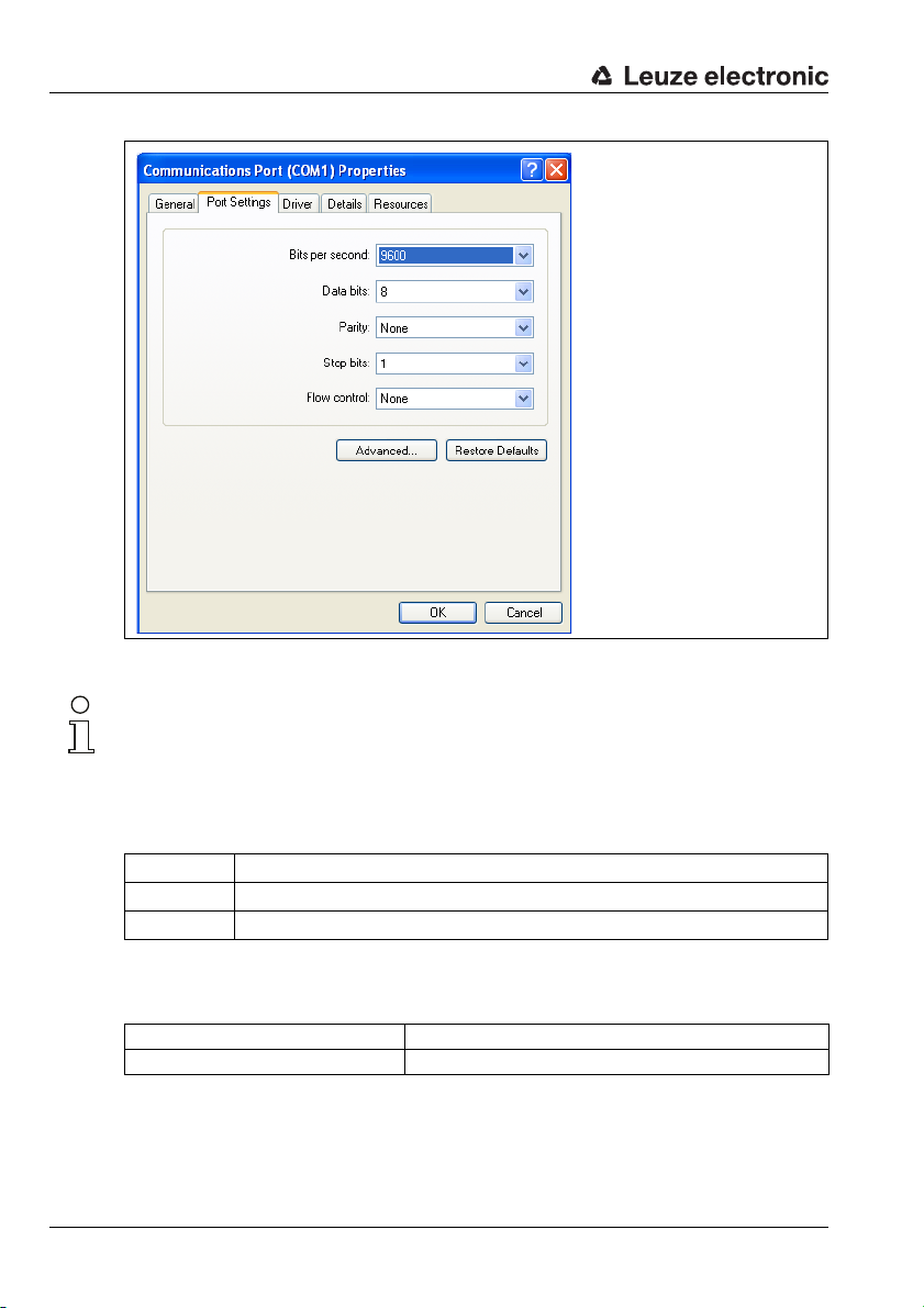
Select the correct COM port (e.g., COM1) and set the interface as follows:
Leuze electronic MA 235i 41
TNT 35/7-24V
Page 44
Configuration
Figure 9.1: COM port settings
Notice!
Observe that STX, data, CR, LF framing must be set on the PC terminal program so that
communication is possible with the connected Leuze device.
Commands
You can now call up information on the MA 235i by sending the following commands.
v General service information.
s Enable memory mode for the last frames.
l The memory mode shows the last RX and TX frames for ASCII and fieldbus.
Table 9.1: Available commands
Information
Version Version information.
Firmware date Firmware date.
Table 9.2: General firmware information
42 MA 235i Leuze electronic
Page 45

Configuration
Selected scanner Currently selected Leuze device (selected via switch S4).
Gateway mode Transparent or Collective mode.
Ring buffer fill level Current fill level of the ring memory in Collective mode (ASCII->Fieldbus).
Received ASCII Frames Number of received ASCII frames.
ASCII Framing Error (GW) Number of received framing errors.
Number of Received CTB's Number of CTB commands.
Number of Received SFB's Number of SFB commands.
Command-Buffer fill level Current fill level of the ring memory in Command mode (fieldbus->ASCII).
Number of send fieldbus frames Number of frames sent via the fieldbus.
Number of invalid commands Number of invalid commands.
Table 9.3: General gateway information
ND Current status of ND bit.
Data loss Current status of data loss bit.
Table 9.4: Current states of the status and control bits
1024 bytes max.
1024 bytes max.
ASCII-Start-Byte Currently configured start byte
ASCII-End-Byte1 Currently configured stop byte 1
ASCII-End-Byte2 Currently configured stop byte 2
ASCII baud rate Currently configured baud rate
ASCII warm start status Indicates whether the ASCII memory has detected and accepted a valid config-
(dependent on switch position S4).
(dependent on switch position S4).
(dependent on switch position S4).
(dependent on switch position S4).
uration.
Table 9.5: ASCII configuration
Input Data length Length of the data received (Rx, 8Byte).
Output Data length Length of the data supplied (Tx, 8Byte).
Node ID Participant address of the address switch.
Baud Rate[kBaud] Set baud rate.
Table 9.6: CANopen parameters MA 235i
TNT 35/7-24V
Leuze electronic MA 235i 43
Page 46

Telegram
10 Telegram
10.1 Structure of the fieldbus telegram
All operations are performed by control and status bits. Two bytes of control information
and two bytes of status information are available for this purpose. The control bits are a part
of the output module and the status bits are a part of the input bytes. The data starts with
the third byte.
If the actual data length is longer than the data length configured in the gateway, only part
of the data is transmitted; the remaining data is lost. In this case, the DL (data loss) bit is set.
The following telegram structure is used between PLC -> fieldbus gateway:
76543210
ND Address 4 Address 3 Address 2 Address 1 Address 0 Broadcast Command
CTB SFB R-ACK Control byte 1
Data byte / parameter byte 0 Data
Data byte / parameter byte 1
…
This telegram structure is used between fieldbus gateway -> PLC:
76543210
ND BO DL BLR DEX SMA W-ACK Status byte 0
mode
Control byte 0
DLC7DLC6DLC5DLC4DLC3DLC2DLC1DLC0 Status byte 1
Data byte / parameter byte 0
Data byte / parameter byte 1
…
Data
Only the data part with the corresponding frame (e.g., STX, CR & LF) is then transmitted
between the fieldbus gateway and the Leuze end device. The two control bytes are
processed by the fieldbus gateway.
The corresponding control and status bits and their meaning are specified in section 10.2
and section 10.3.
Further information on the broadcast control bytes and address bits 0 … 4 can be found in
chapter "Modular interfacing unit MA 3x (S4 switch position C)" on page 93.
44 MA 235i Leuze electronic
Page 47

10.2 Description of the input bytes (status bytes)
10.2.1 Structure and meaning of the input bytes (status bytes)
76543210
ND BO DL BLR DEX SMA W-ACK Status byte 0
DLC7 DLC6 DLC5 DLC4 DLC3 DLC2 DLC1 DLC0 Status byte 1
Telegram
Data byte / parameter byte 0
Data byte / parameter byte 1
…
Data
Table 10.1: Structure of the input bytes (status bytes)
Bits of the input byte (status byte) 0
Bit no. Designation Meaning
0 W-ACK Write-Acknowledge (write confirmation when using buffer)
2 SMA Service mode active(service mode activated)
3 DEX Data exist (data in transmit buffer)
4 BLR Next block ready (new block ready)
5 DL Data loss
6 BO Buffer overflow
7 ND New data only in Transparent mode
Bits of the input byte (status byte) 1
Bit no. Designation Meaning
0…7 DLC0… DLC7 Data Length Code (length of the following user data)
Notice!
T-bit means toggle bit, i.e. this bit changes its state on each event ("0" → "1" or "1" → "0").
TNT 35/7-24V
Leuze electronic MA 235i 45
Page 48

Telegram
10.2.2 Detailed description of the bits (input byte 0)
Bit 0: Write-Acknowledge: W-ACK
This bit is only relevant for writing slave data in blocks, see chapter 11.1.2 (buffer data on
RS 232). It toggles when data from the PLC are sent to the MA with CTB or SFB.
Input data Description Addr. Data
Write-Acknowledge
(write confirmation)
Write handshake
Indicates that the data was successfully sent by the PLC to
W-ACK
the gateway.
Write-Acknowledge is indicated via this bit. The W-ACK bit
is toggled by the fieldbus gateway whenever a transmit command has been successfully executed. This applies both for
the transmission of data to the transmit buffer with the CTB
command and for sending the transmit buffer contents with
the SFB command.
0.0 Bit
Value range Default
type
0->1: Successfully
written
1->0: Successfully
written
0
Bit 2: Service mode active: SMA
Input data Description Addr. Data
Service mode active (SMA)
The SMA bit is set if the service switch is set to "MA" or
SMA
"DEV", i.e. if the device is in either fieldbus gateway or Leuze
device service mode. This is also indicated by a flashing PWR
LED on the front side of the device. Upon changing to the normal operating mode "RUN", the bit is reset.
0.2 Bit
Value range Default
type
0: Device in
operating mode
1: Device in service
mode
0h
Bit 3: Data exist: DEX
This bit is only relevant for reading slave data in Collective mode relevant, see chapter 11.1.1.
Input data Description Addr. Data
Data exist
(data in transmit buffer)
DEX
Indicates that further data is stored in the transmit buffer
which is ready for transmission to the control. This flag bit is
always set to high ("1") by the fieldbus gateway as long as
data is in the buffer.
0.3 Bit
Value range Default
type
0: No data in the
transmit buffer
1: Further data in
the transmit buffer
0h
46 MA 235i Leuze electronic
Page 49

Telegram
Bit 4: Next block ready to transmit: BLR
This bit is only relevant for reading slave data in Collective mode relevant, see chapter 11.1.1.
Input data Description Addr. Data
Next block ready to transmit
(new block ready)
The Block Ready toggle bit changes its state whenever the
BLR
fieldbus gateway has removed received data from the
receive buffer and registered it in the corresponding receivedata bytes. This signals to the master that the quantity of data
indicated in the DLC bits to be present in the input data bytes
originated in the data buffer and is current.
0.4 Bit
Value range Default
type
0->1: Data transmitted
1->0: Data transmitted
0
Bit 5: Data loss: DL
This bit is important for monitoring data transmission in Transparent and Collective mode.
Input data Description Addr. Data
Data loss
(Data transmission monitoring)
This bit is set until the device is reset (bit pattern see chapter
10.4 "RESET function / deleting memory") in case gateway
DL
data was not able to be sent to the PLC and was lost. Furthermore, this bit is set in case the configured data frame,
e.g. 8 bit, should be smaller than the data to be transmitted
to the PLC, e.g. bar code with 20 digits. In this case, the first
8 digits are transmitted to the PLC, the rest are truncated and
are lost. In this process, the Data loss bit is also set.
0.6 Bit
Value range Default
type
0->1:
Data loss
0
Bit 6: Buffer overflow: BO
This bit is only relevant in Collective mode.
Input data Description Addr. Data
Buffer overflow
(buffer overflow)
This flag bit is set to high ("1") when the buffer overflows.
BO
The bit is automatically reset when the buffer again has
memory space available. While the BO bit is set, the RTS signal of the serial interface is deactivated.
The memory size of the gateway for the data of both the PLC
and the Leuze end device is 1 kByte.
0.6 Bit
Value range Default
type
0->1: Buffer overflow
1->0:
Buffer o.k.
0
TNT 35/7-24V
Leuze electronic MA 235i 47
Page 50

Telegram
Bit 7: New data: ND
This bit is only relevant in Transparent mode.
Input data Description Addr. Data
New data
ND
(new data)
This bit is toggled on each data set that is sent from the gateway to the PLC. This can be used to differentiate between
multiple, identical data sets that are sent to the PLC.
0.7 Bit
Value range Default
type
0->1; 1->0:
On each status
change for new data
10.2.3 Detailed description of the bits (input byte 1)
Bit 0 … 7: Data length code: DLC0 … DLC7
Input data Description Addr. Data
Data length code
DLC0 … DLC7
(number of user data in bytes)
Stored in these bits is the number of user data bytes transmitted to the PLC which follow.
1.0 …
1.7
Value range Default
type
1
Bit
FF
10.3 Description of the output bytes (control bytes)
10.3.1 Structure and meaning of the output bytes (control bytes)
76543210
ND Address 4 Address 3 Address 2 Address 1 Address 0 Broadcast
CTB SFB R-ACK Control byte 1
Data byte 1
…
Table 10.2: Structure of the output bytes (control bytes)
Command
(00001b) …
h
(00255b)
h
mode
0
0h (00000b)
Control byte 0
DataData byte 2
Bits of the output byte (control byte) 0
Bit no. Designation Meaning
0 Command mode Command mode
1 Broadcast Broadcast
(only relevant with a connected MA 3x)
2 … 6 Address 0 .. 4 Address bits 0 .. 4
(only relevant with a connected MA 3x)
7ND New data
48 MA 235i Leuze electronic
Page 51

Bits of the output byte (control byte) 1
Bit no. Designation Meaning
0R-ACK Read-Acknowledge
2SFB Send data from transmit buffer
3CTB Copy to transmit-buffer
10.3.2 Detailed description of the bits (output byte 0)
Bit 0: Command mode: Command mode
Telegram
Output data Description Addr. Data
Command mode
This bit is used to activate Command mode. In Command
Command mode
mode, no data is sent by the PLC to the Leuze end device via
the gateway. In Command mode, various bits that execute
corresponding commands depending on the selected Leuze
device can be set in the data- or parameter field. For further
information, see chapter 11.1.3 "Command mode".
0.0 Bit
Value range Default
type
0: Default, transparent data transmission
1: Command mode
0
The following two control bits ("Bit 1: Broadcast: Broadcast" on page 49 and "Bits 2 … 6:
address bits 0 .. 4: address 0 .. 4" on page 49) are only relevant with a connected MA 3x.
With other devices, these fields are ignored.
Bit 1: Broadcast: Broadcast
Output data Description Addr. Data
Broadcast
Broadcast
A broadcast only functions with a multiNet network connected via the MA 3x. If this bit is activated, the gateway
automatically adds the broadcast command "00B" before
the data. This is directed at all participants in the multiNet.
0.1 Bit
Value range Default
type
0: No broadcast
1: Broadcast
0
Bits 2 … 6: address bits 0 .. 4: address 0 .. 4
Output data Description Addr. Data
Address bits 0 .. 4
Address 0..4
As with the broadcast command, individual devices in the
multiNet can also be addressed via the MA 3x . In this case,
the corresponding address of the device precedes the data
field telegram.
0.2
…
0.6
Value range Default
type
00000: Addr. 0
00001: Addr. 1
Bit
00010: Addr. 2
00011: Addr. 3
…
0
Bit 7: New data: ND
TNT 35/7-24V
Output data Description Addr. Data
ND
New data
This bit is needed if several identical pieces of data are to be
sent in sequence.
0.7 Bit
Value range Default
type
0->1; 1->0:
On each status
change for new data
0
Leuze electronic MA 235i 49
Page 52

Telegram
10.3.3 Detailed description of the bits (output byte 1)
Bit 0: Read-Acknowledge: R-ACK
This bit is only relevant for writing slave data in blocks (Collective mode), see chapter 11.1.2.
Output data Description Addr. Data
Read-Acknowledge
(read confirmation)
Toggle bit: Indicates to the fieldbus gateway that the "old"
data has been processed and that new data can be
received. At the end of a read cycle, this bit must be toggled
R-ACK
in order to be able to receive the next data set. This toggle
bit is switched by the master after valid received data has
been read out of the input bytes and the next datablock can
be requested. If the gateway detects a signal change in the
R-ACK bit, the next bytes are automatically written from the
receive buffer to the input data words and the BLR bit toggled. Further toggling erases the memory (to 00h).
1.0 Bit
Value range Default
type
0->1 or
1->0: Successfully
written & ready for
the next transmission
0
Bit 2: Send data from buffer: SFB
This bit is only relevant for writing slave data in blocks (Collective mode), see chapter 11.1.2.
Output data Description Addr. Data
Send data from buffer
(send data from the gateway transmit buffer to the RS 232)
SFB
Toggle bit: changing this bit causes all data which was copied
to the transmit buffer of the fieldbus gateway via the CTB bit
to be transmitted to the RS 232 interface or the connected
Leuze device.
1.2 Bit
Value range Default
type
0->1: Data to
RS 232
1->0: Data to
RS 232
0
50 MA 235i Leuze electronic
Page 53

Telegram
Bit 3: Copy to transmit buffer: CTB
This bit is only relevant for writing slave data in blocks (Collective mode), see chapter 11.1.2.
Output data Description Addr. Data
Copy to transmit buffer
(transmission data to transmit buffer)
Toggle bit: Changing this bit writes the data from the PLC to
CTB
the transmit buffer of the fieldbus gateway. This is used, for
example, for long command strings which must be transmitted to the connected ident device.
The CTB toggle bit is switched whenever transmit data is not
to be sent directly via the serial interface, but instead transferred to the transmit buffer.
Notice!
The state change of the CTB bit signals the MA that the data is going into the buffer; therefore,
it's essential to observe the order!
When the CTB is not used, the telegram (which fits in one cycle) is transmitted directly to
the RS 232 interface. Please make sure it is complete!
10.4 RESET function / deleting memory
For many applications, it is helpful to be able to reset the MA buffer (in Collective mode) or
status bits.
The following bit pattern can be transmitted from the PLC for this purpose (if >20 ms is
pending):
Control byte 0: 10101010 (AAh)
Control byte 1: 10101010 (AAh)
OUT data byte 0/parameter byte 0: AAh
OUT data byte 1/parameter byte 1: AAh
1.3 Bit
Value range Default
type
0->1: Data in buffer
1->0: Data in buffer
0
This sets the memory or status/control bits to 00h.
Please observe that the data image may need to be updated by toggling in Collective mode.
Leuze electronic MA 235i 51
TNT 35/7-24V
Page 54

Modes
11 Modes
11.1 Functionality of the data exchange
The fieldbus gateway has two different modes that can be selected via the PLC:
• Transparent mode (standard setting)
In Transparent mode, all data is sent 1:1 and directly by the serial end device to the
PLC. It is not necessary to use status and control bits here. However, only data bytes
possible for one transmission cycle are transmitted - all others are lost.
The distance between two successive telegrams (without frame) must be more than
20ms, since there is otherwise no clear separation between them.
ASCII characters are typically expected as data content; under certain circumstances,
the MA therefore detects different control characters as invalid characters in the data
range and truncates them. At 00
because unnecessary bytes are also filled with 00
• Collective mode
In Collective mode, the data of the serial end device is stored temporarily in the fieldbus
gateway by toggling the CTB bit and is not sent to the PLC in blocks until prompted
to do so by the PLC.
On the PLC, a status bit (DEX) then signals that new data is ready for retrieval. This
data is then read out from the fieldbus gateway in blocks (toggle bit).
In order to distinguish between the individual telegrams on the PLC, in Collective mode
the serial frame is sent to the PLC in addition to the data.
The size of the buffer is 1 kByte.
in the data range, the MA cuts the telegram off
h
.
h
Notice!
In Collective mode, the CTB and SFB bits are needed for communication handling via the
buffer. Telegrams that can also be completely transmitted in one cycle in Collective mode
(including data frame) go directly through. If PLC data is provided and transferred without a
state change of the CTB bit, it goes directly to the RS 232 interface with the set telegram
data length. Incomplete (incl. data frame) or faulty telegrams can cause error messages in
the connected device!
Combination with the Command mode is possible.
Data exchange in blocks must be programmed on the PLC.
52 MA 235i Leuze electronic
Page 55

11.1.1 Reading slave data in Collective mode (gateway -> PLC)
If the Leuze device transmits data to the fieldbus gateway, the data is stored temporarily in
a buffer. The PLC is signaled via the "DEX" bit that data is ready for retrieval in the memory.
Data is not automatically transmitted.
If no further user data is present in the MA 235i ("DEX" bit = "0"), the "R-ACK" bit must be
toggled once as read confirmation to release data transmission for the next read cycle.
If the buffer still contains more data ("DEX" bit = "1"), the next remaining user data present
in the buffer is transmitted by toggling the "R-ACK" control bit. This process is to be repeated
until the "DEX" bit returns to "0"; all data has then been removed from the buffer. "R-ACK"
must be toggled here again once more as a terminating read confirmation in order to release
data transmission for the next read cycle.
Used status and control bits:
•DLC
•BLR
•DEX
•R-ACK
11.1.2 Writing slave data in Collective mode (PLC -> gateway)
Writing in blocks
The data sent by the master to the slave is first collected in a "transmit buffer" by setting
the "CTB" bit (Copy to transmit buffer). Please observe that data provided is transmitted
directly by toggling the bit.
The data is then sent in the order received from the buffer to the connected Leuze device
via the serial interface with the command: "SFB" (Send data from transmit buffer). Please
don't forget the suitable data frame!
Afterward, the buffer is again empty and can be written with new data.
Modes
Notice!
With this function, it is possible to temporarily store longer data strings in the gateway independent of how many bytes the used fieldbus can transmit at once. With this function, longer
PT sequences or RFID write sequences, for example, can be transmitted, since the connected devices can, in this way, receive their commands (e.g., PT or W) in a continuous string.
The respective frame (STX CR LF) is needed to differentiate between the individual telegrams.
Used status and control bits:
•CTB
•SFB
•W-ACK
Leuze electronic MA 235i 53
TNT 35/7-24V
Page 56

Modes
If PLC data is provided and transferred without a state change of the CTB bit, it goes directly
to the RS 232 interface with the set telegram data length. Incomplete (incl. data frame) or
faulty telegrams can cause error messages in the connected device!
Examples for the activation of a Leuze device
In the data part (starting at byte 2) of the telegram to the gateway, a "+" (ASCII) is sent for
activation.
This means that the hex value "2B" (corresponds to a " +" ) i s to b e e nt e red in control or output
byte 2. To deactivate the reading gate, a "2D" (hex) must be used instead (corresponds to
a "-" ASCII).
76543210
ND Address 4 Address 3 Address 2 Address 1 Address 0 Broadcast
CTB SFB R-ACK Control byte 1
Command
mode
Control byte 0
Data byte 1
…
76543210
00000000 Output byte 0
00000000 Output byte 1
000000
00000000 Output byte 3
76543210
00000000 Output byte 0
00000000 Output byte 1
000000
00000000 Output byte 3
B 2 Output byte 2
B 2 Output byte 2
DataData byte 2
54 MA 235i Leuze electronic
Page 57

Collective mode sequence diagram
Activate Collective
mode
Select
function mode in
PLC via EDS file?
Save toggle bits
as process image
Reception of data
Data is transferred
and must be saved
Is there still data
in the receive buffer?
DEX = 1 set
(status bit 0.3)
Transmit the next
data with toggle bit
R-ACK = ! R-ACK
(control bit 1.0)
Confirm data retrieval
with toggle bit
R-ACK = ! R-ACK
(control bit 1.0)
No
No
Yes
Yes
Sending of data
Number < 254
Enter user data that are to
be sent into output data
words starting at Out 2
DLC = number of
binary-coded data bytes
Send data in the transmit
buffer with the
CTB = ! CTB toggle bit
(control bit 1.3)
All desired data in the buf-
fer?
*)
Command ok?
W-ACK = ! W-ACK
(status bit 0.0)
(Display!)
*)
Command ok?
W-ACK = ! W-ACK
(status bit 0.0)
(Display!)
Send data with the
SFB = ! SFB toggle bit
(control bit 1.2)
No
No
No
Yes
Yes
Send long online commands to the DEV, read RS 232 answer from DEV
Modes
Figure 11.1: Data transmission scheme with long online commands
Leuze electronic MA 235i 55
TNT 35/7-24V
Page 58
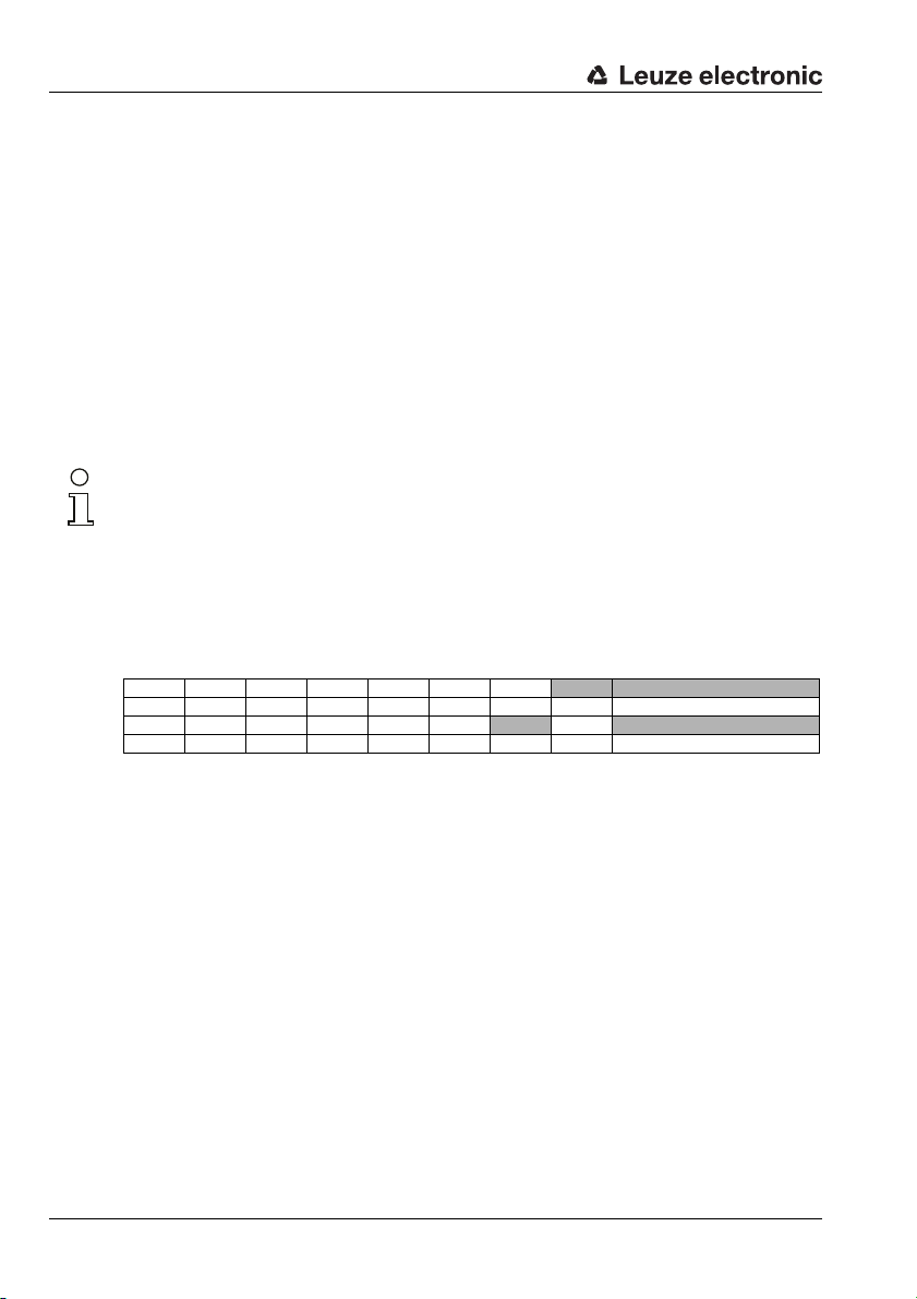
Modes
11.1.3 Command mode
One specific feature is the so-called Command mode, which is defined via the output control
byte 0 (bit 0) ... and enables the control of the connected device per bit.
If the Command mode is activated (Command mode = "1"), no data is sent by the PLC to
the Leuze end device via the gateway. The data from the MA to the PLC is transmitted in
the selected operating mode (Transparent/Collective).
With the Command mode, it is possible to set various device-specific bits in the data- or
parameter field that execute the corresponding serial commands (e.g., v, +, -, etc.). If, for
example, the version of the Leuze end device is to be queried, the corresponding bit is to
be set so that a "v" is sent to the Leuze device with the <STX> v <CR> <LF> frame.
The Leuze end device also answers the gateway with data (e.g. bar code content, NoRead,
device version, etc.) in response to most commands. The answer is immediately passed on
to the PLC by the gateway.
Notice!
The parameters available for the individual Leuze devices are listed in chapter 16.
Command mode cannot be used with hand-held scanners.
Examples for the activation of a Leuze device
In Command mode, control or output byte 0.0 is to be set for activating the Command mode.
Only the corresponding bit (control or output byte 2.1) then needs to be set for activating
and deactivating the reading gate.
76543210
0000000
00000000 Output byte 1
000000
00000000 Output byte 3
1 Output byte 0
10 Output byte 2
56 MA 235i Leuze electronic
Page 59
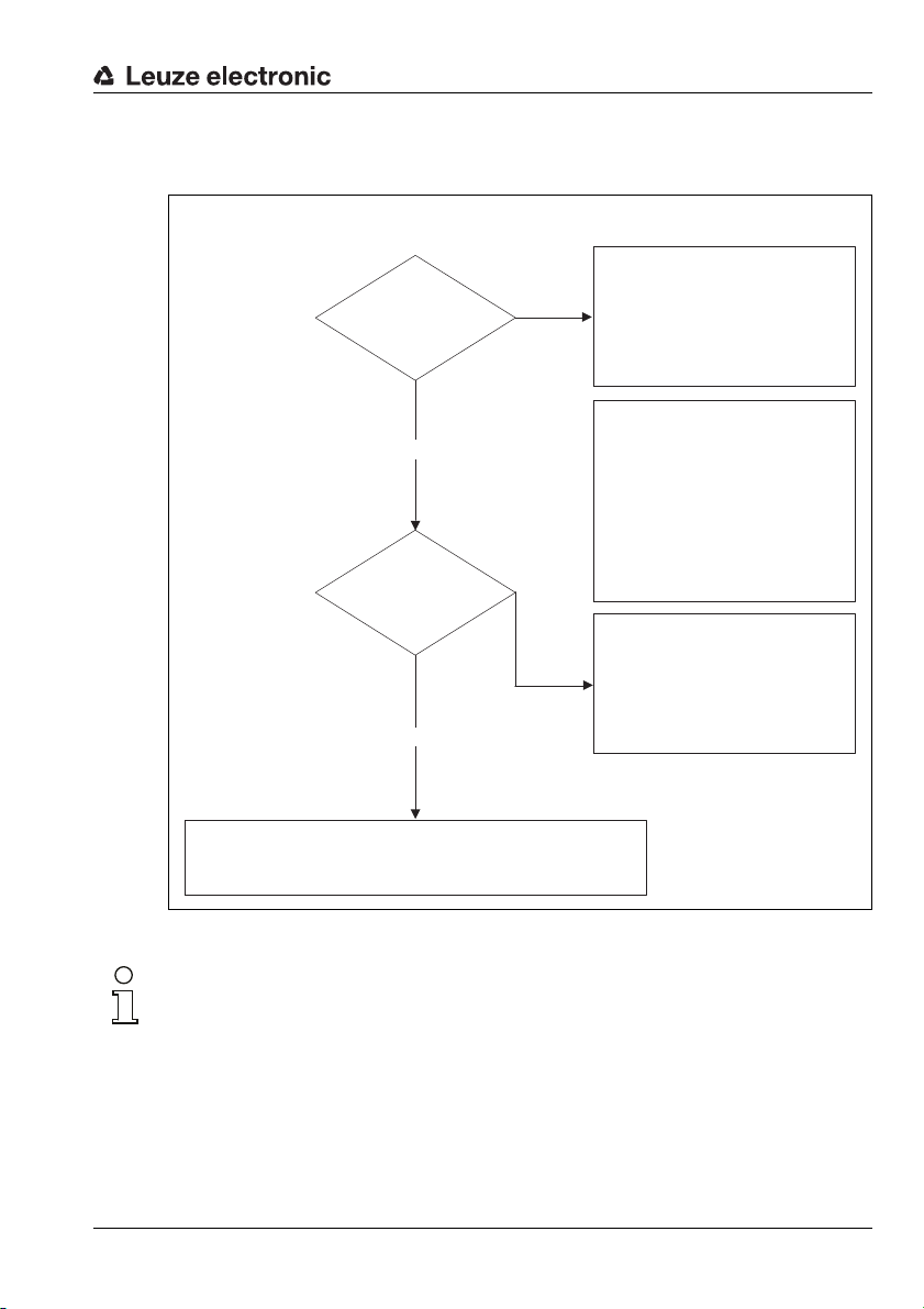
Command mode sequence diagram
Device executes the corresponding function (cf. chap. 16).
For function to be reestablished, the ND bit and the selected bit
in byte 2 must be toggled, byte 0.0 can stay.
No
No
Yes
Yes
Bit 0.0 =1?
Byte 2:
Bit set?
Connected device can only be
addressed via HW or PLC data
telegram
e.g. +
Bit 0.0 signals that the respective bit
is evaluated as a "control bit" in
byte 2, and according to the position of the device selection switch,
executes a corresponding function
on the device via the stored table.
No detectable function
Select bit, or incorrect byte
Set control byte 0, bit 0.0 to 1
Modes
Figure 11.2: Execution of command after activation of the Command mode
Notice!
Further information on fieldbus telegram structure can be found in chapter 10.1. A specification
of all usable commands can be found in chapter "Specifications for Leuze end devices" on
page 80.
Leuze electronic MA 235i 57
TNT 35/7-24V
Page 60

Commissioning and configuration
OnesTens
12 Commissioning and configuration
12.1 Measures to be performed prior to the initial commissioning
Before commissioning, familiarize yourself with the operation and configuration of the
MA 235i.
Before connecting the supply voltage, recheck all connections and ensure that they
have been properly made.
The Leuze device must be connected to the internal RS 232 device interface.
Connecting the Leuze device
Open the housing of the MA 235i and lead the corresponding device cable (see chapter
14.7) through the middle threaded opening.
Connect the cable to the internal device interface (X30, X31 or X32, see chapter 7.5.1).
Use rotary switch S4 (see chapter 8.2.5) to select the connected device.
Now screw the PG cable gland into the threaded opening to provide strain relief and
ensure protection class IP 65.
Set CANopen device address
By setting the CANopen address, the MA 235i is assigned its respective station number.
Each network device is thereby automatically informed that it is a slave on the CANopen
with its specific address and that it is initialized and queried by the PLC.
The CANopen permits an address range from 0 to 127, the MA a range from 0 to 99. Other
addresses must not be used for data communication.
Set the station address of the gateway using the two rotary switches S1 and S2 (ones
and tens places).
Figure 12.1: Rotary switch for setting the address
58 MA 235i Leuze electronic
Page 61

Commissioning and configuration
Set CANopen baud rate on the MA
The CANopen baud rate is defined for the entire network in the planning tool/control. The
baud rate is set on the MA 235i via the baud rate selector switch. Only if the baud rates are
the same is communication with the MA 235i possible.
Set the baud rate of the gateway via the S3 rotary switch to the value defined in the control.
Figure 12.2: Rotary switch for setting baud rate
Switch position Baud rate [kBd]
0 auto
1 10
2 20
3 50
4 100
5 125
6 250
7 500
8 800
9 1000
Finally, close the housing of the MA 235i.
Attention!
Only then may the supply voltage be applied.
Upon startup of the MA 235i, the device selection switch is queried and the gateway
automatically sets itself to the Leuze device.
Leuze electronic MA 235i 59
TNT 35/7-24V
Page 62
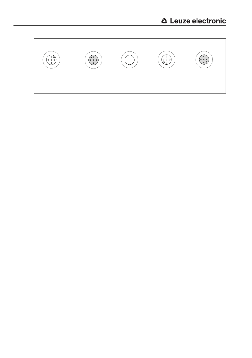
Commissioning and configuration
PWR OUT
VOUT
123
4
SWIO_2
GND
FE
5
PWR IN
SWIO_1
SWIO_2
321
4
5
GND VIN
FE
LEUZE Device
HOST / BUS IN
SWIO_1
V+
CAN_H
143
2
5
DRAIN
V-
CAN_L
1
2
3
4
5
BUS OUT
V+
CAN_H
DRAINV-
CAN_L
M12 connector
(A-coded)
M12 socket
(A-coded)
M12 connector
(A-coded)
M12 socket
(A-coded)
Figure 12.3: Connections of the MA 235i seen from below, device on mounting plate
Check the applied voltage. It must be in the range between +18V … 30VDC.
Connecting functional earth FE
Ensure that the functional earth (FE) is connected correctly.
Unimpaired operation is only guaranteed when the functional earth is connected properly.
All electrical disturbances (EMC couplings) are discharged via the functional earth connection.
On delivery, the SWIO 1/2 are connected in parallel on PWR IN/OUT. This connection can
be separated with a jumper.
12.1.1 Connecting the power supply and the bus cable
Ideally, use the ready-made cables listed in chapter 14.5.3 to connect the gateway to the
power supply via the PWR IN connection.
The ready-made cables listed in chapter 14.6.4 are preferred for connecting the gateway
to the fieldbus via the HOST / BUS IN connection.
If applicable, use the BUS OUT connection if you would like to construct a network with
linear topology.
12.2 Starting the device
Apply the supply voltage +18 … 30VDC (typ. +24VDC); the MA 235i starts up.
The PWR LED displays that it is ready for operation.
60 MA 235i Leuze electronic
Page 63
12.3 MA 235i in the CANopen system
Install the EDS file corresponding to the MA 235i in your planning tool/the control.
Notice!
You can find the EDS file at: www.leuze.com
The MA 235i is configured in the planning tool/control by means of the EDS file. The MA 235i
is assigned an address in the planning tool, which then has to be set in the MA 235i via the
S1 and S2 address switches. Only if the addresses are the same between the MA 235i and
the control can communication be established.
After all parameters have been set in the planning tool/control, the download to the MA 235i
takes place. The set parameters are now stored on the MA 235i.
Afterwards, all MA 235i parameters should be stored via upload in the control. This aids in
retaining the parameters during device exchanges, as they a re now also stored centrally in
the control.
The CANopen baud rate is defined for the entire network in the planning tool/control. The
baud rate is set on the MA 235i via the S3 baud rate selector switch.
Only if the baud rates are the same is communication with the MA 235i possible.
In a CANopen network, all participants have in principle equal privileges. Each participant
can initiate its data transmission independently. Here, the arbitration specified by the CIA
controls the access of the individual participants to the network. Generally, each CAN participant listens in on the bus. The transmission process is started only if the bus is not occupied
by another CAN participant. When transmitting, the current bus status is always compared
to the own transmitted frame.
If several participants start a transmission simultaneously, the arbitration process decides
which participant gains access to the network next. The individual participants are integrated into a prioritization scheme via their bus address and the type of data to be transmitted (index address of the data). Process data (PDOs) of a device are transmitted with a
higher priority than, for example, variable objects (SDOs) of a device.
The node address of the participant is another criterion for prioritizing a participant in the
network. The smaller the node address, the higher the priority of the participant in the
network.
Since every participant compares its own priority with that of the other participants at the
time of bus access, the participants with low priority discontinue their transmission activities
immediately. The participant with the highest priority obtains temporary access to the bus.
The arbitration process controls the access of all participants so that even participants with
a low priority have access to the bus.
Commissioning and configuration
TNT 35/7-24V
Leuze electronic MA 235i 61
Page 64

Commissioning and configuration
12.4 Starting the MA 235i in the CANopen system
During starting up, the gateway runs through different states which are explained in brief in
the following.
INIT
The MA 235i initializes itself. No direct communication between the master and MA 235i is
possible. The CANopen master will transfer the MA 235i step by step into the "operational"
state.
In the status change from "INIT" to "PREOP", the TwinCAT or master writes the so-called
CANopen address (=station address) to the respective register of the CANopen slave
controller (here: MA 235i). This CANopen address is typically specified in relation to the position, i.e., the master's address is 1000, the first slave's address is 1001, etc. This is also
called the auto-increment method.
PRE-OPERATIONAL
The master and the MA 235i exchange application-specific initializations and devicespecific parameters. In the PRE-OPERATIONAL state, configuration is initially possible via
SDOs only.
SAFE-OPERATIONAL
The "Start Input Update" command puts the gateway into the "Safe-Operational" state. The
master produces output data, but input data are not considered. This means the MA 235i
does not return output data (=PLC input data) in SAFEOP. The gateway does not process
input process data (=PLC output data). Mailbox communication via CoE services is possible.
OPERATIONAL
The "Start Output Update" command puts the gateway into the OPERATIONAL state. In
this state, the MA 235i supplies valid input data and the master valid output data. After the
MA 235i has detected the data received via the process data service, the state transition is
confirmed by the MA 235i. If the activation of the output data was not possible, the gateway
remains in the SAFE OPERATIONAL state and outputs an error message.
12.4.1 Device profile
CANopen describes the characteristics of participants in so-called profiles. However, a
device profile for gateways is not defined.
The MA 235i is designed as a slave participant and cannot take on master functionality.
62 MA 235i Leuze electronic
Page 65

12.4.2 Object directories
All process data and parameters are stored as objects in the MA 235i. The object directory
of the MA 235i is the compilation of all process data and parameters of the gateway.
An object directory is structured such that some objects within a device profile are mandatory while others are freely definable and stored in the manufacturer-specific object area.
The objects are uniquely identified using an index addressing scheme. The structure of the
object directory, the assignment of the index numbers, as well as some mandatory entries
are specified in the CIA standard DS301 for CANopen.
EDS file
For the user, the object directory of the MA 235i is stored as an EDS file (Electronic Data
Sheet).
The EDS file contains all objects with index, sub-index, name, data type, default value,
minimum and maximum, and access privileges. That means the EDS file describes the entire
functionality of the MA 235i, and it is possible to adjust both the communication of the
gateway with the control and the RS 232 interface.
Notice!
The size of the input and output data is permanently set for CANopen: the MA 235i always
provides the process data for transmission in this form: 8 bytes Tx and 8 bytes Rx.
The EDS file has the name MA 235i.eds and is available for download on the Leuze home
page.
Vendor ID for the MA 235i
The Vendor ID assigned by Leuze electronic for the MA 235i is 121h = 289d.
Detailed information on the device description file and the object directory can be
found in chapter 12.4.6.
Commissioning and configuration
12.4.3 SDOs and PDOs
The data exchange in CANopen distinguishes between service data objects (SDOs), which
are used for transmitting the service data (parameters) from and to the object directory, and
process data objects (PDOs), which are used to exchange the current process states.
12.4.4 SDOs
By using SDOs, all entries of the object directory can be accessed. Within one SDO call,
only one object can be accessed at any one time. For this reason, a service data telegram
must have a protocol structure which describes the exact target address by means of
index and sub-index addressing. SDO telegrams place a part of the SDO addressing into
the user data area. Eventually, a user data area with a width of 4 bytes out of the possible
8 bytes of user data remains for each SDO telegram.
The target address always responds to SDO transfers.
In the following, the index and sub-index address of the MA 235i parameters and vari-
ables can be found in the individual object descriptions.
Leuze electronic MA 235i 63
TNT 35/7-24V
Page 66

Commissioning and configuration
12.4.5 PDOs
PDOs are objects (data, variables and parameters) from the object directory compiled
(mapped) by the device manufacturer. A maximum of 8 bytes of user data from various
objects can be mapped into one PDO.
A PDO can be received and evaluated by each participant (node). The model is referred to
as the producer-consumer procedure.
Since there is no protocol structure in the telegra m of a PD O, t he p articipants in the network
for whom these data are intended mu st k now how the user data in the data area of the PDO
are structured (which data are stored where in the user data area).
The exchange of process data is supported by the MA 235i via the following accesses:
• Event-controlled data transfer
Here, the data of a node are transmitted as a message whenever a change to the present state occurs.
• Polling with remote frames
The CAN node which has been defined as master in the network requests the desired
information via query (via remote frame). The participant which has this information
(or the required data) responds by sending the requested data.
• Synchronized mode
CANopen permits simultaneous querying of inputs and states of different participants
and the simultaneous change of outputs or states. For this purpose, one uses the synchronization telegram (SYNC) transmitted by a master.
The SYNC telegram is a broadcast to all network devices with high priority and without
data content. Generally, the master sends the SYNC telegram cyclically.
Participants working in synchronized mode read their data when receiving the SYNC
message and then transmits them immediately afterwards as soon as the bus permits
this (see explanation regarding arbitration process).
As the SYNC process can very quickly lead to high bus loads, another distinction is
made between "event-controlled synchronization" and a "timer synchronization".
• Time-controlled transmission
In this case, the transmission of a PDO is triggered when an adjustable time period
has elapsed. The time-controlled transmissions are set individually for each PDO via
the so-called "inhibit time" or an "event timer". The respective parameters can be
found in the objects 1800
• Node monitoring
Heartbeat and guarding mechanisms are available for failure monitoring of the
MA 235i. This is particularly important for CANopen, as the MA 235i may not respond
regularly in the event-controlled operating mode. In case of guarding, the participants
are cyclically queried for their state via data request telegrams (remote frame). In case
of heartbeat, the nodes transmit their state themselves.
Heartbeat and guarding / life time are standard communication objects from the
DS301 CANopen specification. The corresponding objects here are:
- Heartbeat 1017
- Guarding / Life time factor 100Ch and 100D
to 1803h for the corresponding PDOs.
h
h
h
64 MA 235i Leuze electronic
Page 67

12.4.6 Object index
The object directory of the MA 235i is the compilation of all process data and parameters
of the MA.
The following overview table shows all objects supported by the MA 235i.
Object address in hex CANopen-specific object area
1000 Device Type
1008 Manufacturer Device Name (contains the device name of the manufacturer)
1018 Identity Object (contains general information regarding the device)
2000 Inputs (Input Data, 8 bytes by 8 bytes (Rx))
2200 Outputs (Output Data, 8 bytes by 8 bytes (Tx))
3000 Serial line mode
3001 Serial Settings (RS 232)
Afterwards, you will find the respective detailed descriptions of the individual objects.
12.4.6.1 Object 1000h Device Type
The object describes the MA 235i device type.
Commissioning and configuration
Index Sub-
(hex) (hex) Minimum Maximum Default
1000 -- Device type u32 ro -- -- 0000
Name Data type Access Value range Remark
index
TNT 35/7-24V
Leuze electronic MA 235i 65
Page 68

Commissioning and configuration
12.4.6.2 Object 1008h Manufacturer Device Name
This object contains the name of the gateway.
Index Sub-
(hex) (hex) Minimum Maximum Default
1008 --
Name Data type Access Value range Remark
index
Manufac-
turer Device
Name
u32 ro -- --
12.4.6.3 Object 1018h Manufacturer Device Name
This object contains general specifications about the MA 235i.
Index Sub-
(hex) (hex) Minimum Maximum Default
1018 01 Vendor ID u32 ro -- -- 121
Name Data type Access Value range Remark
index
Product
02
Code
03 Revision u32 ro -- --
Serial
04
Number
u32 ro -- -- F1
u32 ro -- --
The Vendor ID assigned by Leuze electronic for the MA 235i is 121
12.4.6.4 Object 2000h Inputs
The object describes the input data of the MA 235i, which is transmitted cyclically, 8 bytes
by 8 bytes (Rx).
Index Sub-
index
(hex) (hex) Minimum Maximum Default
2000 -- 8 Byte Input u32 rw -- x00
Name Data type Access Value range Remark
12.4.6.5 Object 2200h Outputs
The object describes the output data of the MA 235i, which is transmitted cyclically, 8 bytes
by 8 bytes (Tx).
MA235i
V1.x.x.x
h
h
--
--
= 289d.
h
Device names of
the manufacturer
Manufacturer ID
number
Index Sub-
index
(hex) (hex) Minimum Maximum Default
2200 -- 8 Byte Output u32 rw -- -- x00
Name Data type Access Value range Remark
66 MA 235i Leuze electronic
Page 69

12.4.6.6 Object 3000h Serial Line Mode
The object describes the function mode of the MA 235i.
Commissioning and configuration
Index Sub-
(hex) (hex) Minimum Maximum Default
3000 -- Data Mode u32 rw -- --
Name Data type Access Value range Remark
index
Parameter value:
0 = Transparent Mode
1 = Collective Mode
12.4.6.7 Object 3001h Serial Settings
The object describes the serial RS 232 settings of the MA 235i.
Index Sub-
(hex) (hex) Minimum Maximum Default
3001 --
Name Data type Access Value range Remark
index
Serial
Settings
Use Rotary
01
Switch
02 Baud Rate u32 rw -- --
03 Data Bits u32 rw -- -- 8 Data Bits (8)
04 Parity u32 rw -- -- None (1)
05 Stop Bits u32 rw -- -- 1 Stop Bit (1)
u32 rw -- --
u32 rw -- --
Use Rotary Switch
Parameter value:
0 = use rotary switch (default)
1 = use EDS settings
RS 232 Baud Rate
Parameter value:
3 = 300
6 = 600
12 = 1200
24 = 2400
48 = 4800
96 = 9600 (default)
192 = 19200
384 = 38400
576 = 57600
1152= 115200
Transparent
Mode (0)
Use Rotary
Switch (1)
9600 Baud
(96)
TNT 35/7-24V
Leuze electronic MA 235i 67
Page 70

Commissioning and configuration
RS 232 Data Bits
Parameter value:
7 = 7 bits
8 = 8 bits (default)
RS 232 Parity
Parameter value:
1 = none (default)
2 = even
3 = odd
RS 232 Stop Bits
Parameter value:
1 = 1 bit (default)
2 = 2 bits
68 MA 235i Leuze electronic
Page 71

Commissioning and configuration
12.5 Setting the read parameters on the Leuze device
Commissioning the Leuze device
To commission a read station, you must prepare the Leuze device on the MA 235i for its
reading task. Communication with the Leuze device occurs via the service interface.
Notice!
For further information on connecting and using the service interface, see chapter 9 "Configuration".
To do this, connect the Leuze device to the MA 235i.
Depending on the Leuze device, this occurs either via a connection cable (accessory no.:
KB 031-1000) or directly on the MA 235i. The service connector and corresponding
switches can be accessed with the housing cover open.
Select the "DEV" service switch position.
Connect the service interface; call up the terminal program
Connect your PC to the service connector via the RS 232 cable.
On the PC, call up a terminal program (e.g., BCL-Config) and check whether the interface
(COM 1 or COM 2) to which you have connected the MA 235i is set to the following Leuze
standard setting: 9600 baud, 8 data bits, no parity, 1 stop bit and STX, data, CR, LF.
You can download the config. tool from www.leuze.com for BCL, RFID, etc.
Leuze electronic MA 235i 69
TNT 35/7-24V
Page 72

Commissioning and configuration
In order to communicate with the connected Leuze device, the STX, data, CR, LF framing
must be set on the PC terminal program, as the Leuze device is preconfigured ex works for
this frame character.
STX (02h): Prefix 1
CR (0Dh): Postfix 1
LF (0Ah): Postfix 2
Operation
Switch the MA 235i to switch position "RUN" (operation).
The Leuze device is now connected to the fieldbus. Activation of the Leuze device can now
occur via the switching input on the MA 235i, via the process data word Out bit 1 (bit 0.2)
or by transmitting a "+" command to the Leuze device (see chapter 16 "Specifications for
Leuze end devices"). For further information on the fieldbus transmission protocol, see see
chapter 10 "Telegram".
Reading out information in service mode
Set the service switch of the gateway to switch position "MA" (gateway).
Send a "v" command to call up all service information of the MA 235i.
An overview of the available commands and information can be found in chapter "Reading
out information in Service mode" on page 41.
12.5.1 Specific feature for the use of hand-held scanners (bar code and 2D devices, combi devices with RFID)
Notice!
A description of the device configuration and the required codes can be found in the
respective documentation at www.leuze.com.
12.5.1.1 Cable-connected hand-held scanners on the MA 235i
All hand-held scanners and mobile combi devices available in the Leuze electronic product
line can be used with the corresponding connection cable.
When using the MA 235i, the voltage supply of the hand-held scanner (4.75 … 5.25VDC/
at 1A) can be connected to the interface by means of a cable via the 9-pin Sub-D connector
(voltage on PIN 9). The corresponding cable is to be selected for the respective hand-held
scanner and ordered separately. The 9-pin Sub-D cable (KB JST-HS-300, part no.
50113397) is connected to this cable, which is connected to the MA 235i. This cable must
also be ordered separately.
In this example, triggering occurs by means of a trigger button on the hand-held scanner.
Notice!
When using third-party devices, check the pin assignment and interface settings without fail
and adjust them if necessary.
70 MA 235i Leuze electronic
Page 73

Commissioning and configuration
12.5.1.2 Wireless hand-held scanners on the MA 235i
All wireless hand-held scanners and mobile combi devices available in the Leuze electronic
product line can be used with the corresponding connection cable via the base station.
A 230VAC connection (socket) is usually necessary for the charging station. Here, a data
connection of the charging station is established with the MA 235i. The corresponding cable
is to be selected for the respective hand-held scanner and ordered separately. The 9-pin
Sub-D cable (KB JST-HS-300, part no. 50113397) is connected to this cable, which is
connected to the MA 235i. This cable must also be ordered separately.
In this example, triggering occurs by means of a trigger button on the hand-held scanner.
The following codes for configuring the devices are necessary for these devices as well.
12.5.2 Specific features in the operation of an RFM/RFI
When using the MA 235i in connection with an RFID device, we recommend a data width
of at least 24 bytes to be able to transmit information to or from the reader in a telegram.
Shown here is a sample telegram for a write command in combination with an RFID device.
Notice!
Also note that all characters which are sent to a transponder are hex-encoded ASCII
characters. Each of these (hexadecimal) characters is, in turn, to be handled as an individual
ASCII character and converted to hexadecimal format for transmission via the fieldbus.
Example:
76543210
00 00 00 00 00 00 00 00 Control byte 0
00 00 00 00 00 00 00 00 Control byte 1
34 35 31 31 30 35 30 57
00 00 34 37 33 37 35 36
Data
HEX 5730353031313534363537333734
CHAR W0501154657374
Plain text T e s t
Leuze electronic MA 235i 71
TNT 35/7-24V
Page 74
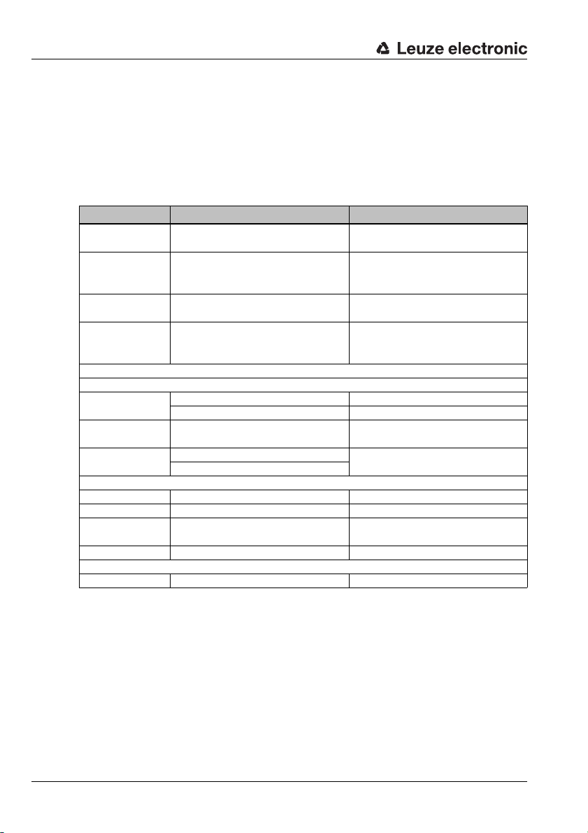
Diagnostics and troubleshooting
13 Diagnostics and troubleshooting
If problems should occur during commissioning of the MA 235i you can refer to the following
table. Typical errors and their possible causes are described here as well as tips for their
elimination.
13.1 General causes of errors
Error Possible error causes Measures
No data to the PLC Device setting incorrect.
No data sporadically
and/or the device
"stalls"
Data loss
(DL bit)
Data in the RS 232
instead of in the
buffer
PWR status LED on the circuit board
Off
Green/orange,
flashing
Continuous orange
light
PWR LED on the housing (see figure 5.1 on page 22)
Off No supply voltage connected to the device. Check supply voltage.
Green, flashing SERVICE active. Service switch on RUN.
Red, flashing Incorrect baud rate / address.
Red continuous light Device error. Send the device to customer service.
CAN LED on the housing (see figure 5.1 on page 22)
Off No connection Check wiring/IP address.
Table 13.1: General causes of errors
Problems with the voltage supply.
Data telegram longer than the bus
telegram in bus cycle/memory size.
Incorrect order
No supply voltage connected to the device. Check supply voltage.
Hardware error. Send the device to customer service.
Device in boot mode.
Device error.
Firmware update failed.
Adjust device settings (data protocol, baud
rate, etc.).
Check voltage range, supply separately if
needed.
Increase in bus telegram length.
Toggle out data earlier.
Correct order:
Provide data, toggle CTB.
No valid firmware, send device to customer service.
Send the device to customer service.
Check switch settings.
Check baud rate or address.
72 MA 235i Leuze electronic
Page 75

13.2 Interface errors
Error Possible error causes Measures
No communication via
CANopen interface
CAN continuous red
light LED
Diagnostics and troubleshooting
Incorrect wiring. Check wiring.
Check switch settings:
Incorrect baud rate / address
different baud rate setting in control and MA: no communication.
Address >99: no communication.
Baud rate selector switch S3.
Address switch S1, S2.
Incorrect wiring.
Sporadic errors at the
CANopen interface
Figure 13.1: Interface error
Notice!
Please use chapter 13 as a master copy should servicing be required.
Cross the items in the "Measures" column which you have already examined, fill out the
following address field and fax the pages together with your service contract to the fax
number listed below.
Effects due to EMC.
Overall network expansion
exceeded.
Check wiring.
In particular, check wire shielding.
Check the cable used.
Check shielding (shield covering in place up to
the clamping point).
Check grounding concept and connection to
functional earth (FE).
Avoid EMC coupling caused by power cables laid
parallel to device lines.
Check max. network expansion as a function of
the max. cable lengths.
Customer data (please complete)
Device type:
Company:
Contact partner / department:
Phone (direct):
Fax:
Street / No:
ZIP code/City:
Country:
TNT 35/7-24V
Leuze Service fax number:
+49 7021 573 - 199
Leuze electronic MA 235i 73
Page 76

Type overview and accessories
14 Type overview and accessories
14.1 Part number code
MA 2xx i
Interface 04 PROFIBUS DP
14.2 Type overview
Type designation Description Description
MA 204i PROFIBUS gateway 50112893
MA 208i Ethernet TCP/IP gateway 50112892
MA 235i CANopen gateway 50114154
MA 238i EtherCAT gateway 50114155
MA 248i PROFINET-IO RT gateway 50112891
MA 255i DeviceNet gateway 50114156
MA 258i EtherNet/IP gateway 50114157
Table 14.1: Type overview MA 2xxi
i = Integrated fieldbus technology
08 Ethernet TCP/IP
35 CANopen
38 EtherCAT
48 PROFINET RT
55 DeviceNet
58 EtherNet/IP
MA Modular interfacing unit
14.3 Accessory terminating resistor
Type designation Description Part no.
TS 01-4-SA 120 ohm M12 terminating resistor for CANopen 50040099
Table 14.2: Accessory terminating resistor
14.4 Accessory connectors
Type designation Description Description
KD 095-5A M12 socket for voltage supply 50020501
KS 095-4A M12 connector for SW IN/OUT 50040155
Table 14.3: Connectors for the MA 235i
74 MA 235i Leuze electronic
Page 77

Type overview and accessories
M12 socket
(A-coded)
M12 connector
(A-coded)
14.5 Accessory ready-made cables for voltage supply
14.5.1 Contact assignment of PWR connection cable
PWR IN (5-pin socket, A-coded)
PWR IN
SWIO_2
2
1
SWIO_1
GNDVIN
3
5
4
FE
PWR OUT
SWIO_2
2
GND VOUT
3
FE
5
4
SWIO_1
1
Pin Name Core color
1VIN brown
2SWIO_2 white
3GND blue
4SWIO_1 black
5FE gray
Thread FE bare
PWR OUT (5-pin connector, A-coded)
Pin Name Core color
1VOUT brown
2SWIO_2 white
3GND blue
4SWIO_1 black
5FE gray
Thread FE bare
14.5.2 Specifications of the cables for voltage supply
Operating temperature range in rest state: -30°C … +70°C
in motion: 5° C … +70°C
Material sheathing: PVC
Bending radius > 50mm
Leuze electronic MA 235i 75
TNT 35/7-24V
Page 78

Type overview and accessories
1
2
3
4
5
BUS IN
V+
CAN_H
DRAINV-
CAN_L
BUS OUT
V+
CAN_H
1
4
3
2
5
DRAIN
V-
CAN_L
M12 socket
(A-coded)
M12 connector
(A-coded)
14.5.3 Order codes of the cables for voltage supply
Type designation Description Part no.
K-D M12A-5P-5m-PVC
K-D M12A-5P-10m-PVC
Table 14.4: PWR cables for the MA 235i
M12 socket for PWR, axial plug outlet,
open cable end, cable length 5m
M12 socket for PWR, axial plug outlet,
open cable end, cable length 10m
50104557
50104559
14.6 Accessory ready-made cables for bus connection
14.6.1 General information
• Cable KB DN… for connecting to CANopen via M12 connector
• Standard cable available in lengths from 2 … 30m
• Special cables on request
14.6.2 Contact assignment of M12-CANopen connection cable KB DN…
CANopen connection cable (5-pin socket/plug, A-coded)
Pin Name Core color Remark
1Drain - Shield
2V+red Supply voltage data V+
3V-black Supply voltage data V-
4 CAN_H white Data signal CAN_H
5 CAN_L blue Data signal CAN_L
Thread FE - Functional earth (housing)
76 MA 235i Leuze electronic
Page 79

Type overview and accessories
14.6.3 Specifications of M12-CANopen connection cable KB DN…
Operating temperature range in rest state: -40°C … +80°C
in motion: -5°C … +80°C
Material the cables comply with the CANopen requirements,
free of halogens, silicone and PVC
Bending radius > 80 mm, suitable for drag chains
14.6.4 Order codes of M12-CANopen connection cable KB DN…
Type designation Remark Part no.
KB DN/CAN-2000-BA M12 socket for BUS IN, axial connector, open cable end,
KB DN/CAN-5000-BA M12 socket for BUS IN, axial connector, open cable end,
KB DN/CAN-10000-BA M12 socket for BUS IN, axial connector, open cable end,
KB DN/CAN-30000-BA M12 socket for BUS IN, axial connector, open cable end,
KB DN/CAN-2000-SA M12 connector for BUS OUT, axial connector, open cable end,
KB DN/CAN-5000-SA M12 connector for BUS OUT, axial connector, open cable end,
KB DN/CAN-10000-SA M12 connector for BUS OUT, axial connector, open cable end,
KB DN/CAN-30000-SA M12 connector for BUS OUT, axial connector, open cable end,
KB DN/CAN-1000-SBA M 12 plug + M12 socket for CANopen, axial connectors,
KB DN/CAN-2000-SBA M 12 plug + M12 socket for CANopen, axial connectors,
KB DN/CAN-5000-SBA M 12 plug + M12 socket for CANopen, axial connectors,
Table 14.5: Bus connection cable for the MA 235i
cable length 2m
cable length 5m
cable length 10m
cable length 30m
cable length 2m
cable length 5m
cable length 10m
cable length 30m
cable length 1m
cable length 2m
cable length 5m
50114692
50114696
50114699
50114701
50114693
50114697
50114700
50114702
50114691
50114694
50114698
TNT 35/7-24V
Leuze electronic MA 235i 77
Page 80

Type overview and accessories
14.7 Accessory ready-made cables for connecting Leuze Ident devices
14.7.1 Order codes for the device connection cables
Type designation Description Part no.
KB JST-3000 MA 31, BCL 90, IMRFU-1(RFU), cable length 3m 50115044
KB JST-HS-300 Hand-held scanner, cable length 0.3m 50113397
KB JST-M12A-5P-3000 BPS 8, BCL 8, cable length 3 m 50113467
KB JST-M12A-8P-Y-3000 LSIS 4x2i, cable length 3 m 50113468
KB JST-M12A-8P-3000 LSIS 122, LSIS 222, cable length 3m 50111225
K-D M12A-5P-5m-PVC Voltage supply, cable length 5m 50104557
K-D M12A-5P-10m-PVC Voltage supply, cable length 10m 50104559
K-DS M12A-MA-5P-3m-S-PUR ODS 96B with RS 232 50115049
K-DS M12A-MA-8P-3m-S-PUR ODSL 30/D 232-M12 50115050
K-DS M12A-MA-5P-3m-1S-PUR Konturflex Quattro RSX 50116791
KB 500-3000-Y BCL 500i, cable length 3m 50110240
KB 301-3000-MA200 BCL 300i, cable length 3 m 50120463
Table 14.6: Device connection cables for the MA 235i
Notice!
The BCL 22 devices with JST connector, RFM xx and RFI xx can be connected directly with
the injection molded device cable.
14.7.2 Contact assignment for the device connection cables
K-D M12A-5P-5000/10000 connection cable (5-pin with molded connector), open cable end
Pin Core color
1brown
2white
3blue
4black
5gray
KB JST 3000 (RS 232 connection cable, JST pin strip 10-pin, open cable end)
Signal Core color JST 10-pin
TxD 232 red 5
RxD 232 brown 4
GND orange 9
FE shield 10
78 MA 235i Leuze electronic
Page 81

15 Maintenance
15.1 General maintenance information
The MA 235i does not require any maintenance by the operator.
15.2 Repairs, servicing
Repairs to the device must only be carried out by the manufacturer.
Contact your Leuze distributor or service organization should repairs be required.
The addresses can be found on the inside of the cover and on the back.
Notice!
When sending devices to Leuze electronic for repair, please provide an accurate description
of the error.
15.3 Disassembling, packing, disposing
Repacking
For later reuse, the device is to be packed so that it is protected.
Notice!
Electrical scrap is a special waste product! Observe the locally applicable regulations
regarding disposal of the product.
Maintenance
Leuze electronic MA 235i 79
TNT 35/7-24V
Page 82

Specifications for Leuze end devices
16 Specifications for Leuze end devices
Serial interface and Command mode
The corresponding Leuze end device can be selected while configuring the fieldbus gateway
(see chapter 9 "Configuration").
The exact specifications for the individual Leuze end devices can be found in the following
sections and in the device description.
The corresponding serial command is sent to the Leuze end device in Command mode. To
send the corresponding command to the RS 232 device after activating the Command
mode in byte 0 (control bit 0.0), set the corresponding bit in byte 2.
The Leuze end device also responds to most commands by sending data, such as the bar
code contents, NoRead, device version, etc., back to the gateway. The answer is not evaluated by the gateway, but is instead passed on to the PLC.
For the BPS 8, BPS 300i and hand-held scanners, a number of specific features are to be
noted.
Notice!
Please note that Leuze only assumes liability for the function of Leuze products. When using
third-party devices, Leuze does not assume liability for the function of third-party devices!
16.1 Standard setting, KONTURflex (S4 switch position 0)
This switch position can be used with almost all devices, since a data frame is transmitted
along with it if necessary. A 00h in the data range of the control is interpreted as the end of
a telegram/invalid, however.
The distance between two successive telegrams (without frame) must be more than 20ms
in this switch position, since there is otherwise no clear separation between them. If necessary, the settings have to be adjusted on the device.
Leuze measuring sensors with RS 232 interface (such as a KONTURflex Quattro RS) do not
necessarily use a telegram frame, which is why these are also operated in switch position 0.
Specifications for the serial interface
Default parameter Standard
Baud rate 9600
Data mode 8N1
Handshake no
Protocol framing protocol without acknowledgment
Frame <Data>
Data Mode transparent
Notice!
The data frame is specified via the switch position.Only the data mode and the baud rate
can also be set via the EDS file.
The factory setting corresponds to S4 switch position 0.
80 MA 235i Leuze electronic
Page 83

Specifications for Leuze end devices
KONTURflex specifications
Settings on the MA 235i
• CANopen address is freely selectable
• Device selection switch at position "0"
Settings on the CANopen
• Produced/Consumed data settings:
Dependent on number of beams used, but at least "8 bytes In"
• User Parameters:
"Transparent Mode", "Use EDS Settings", Baudrate 38400, "8 Data Bits", "No parity",
"2 Stop Bits"
KONTURflex settings
First, the following settings are to be performed on the device using KONTURFlex-Soft:
• Either "Autosend (fast)" or "Autosend with data in Modbus format"
• Repeat time "31.5ms"
• Autosend baud rate "38.4 KB"
• 2 stop bits, no parity
Leuze electronic MA 235i 81
TNT 35/7-24V
Page 84

Specifications for Leuze end devices
16.2 Bar code reader BCL 8 (S4 switch position 1)
Specifications for the serial interface
Default parameter BCL 8
Baud rate 9600
Data mode 8N1
Handshake no
Protocol framing protocol without acknowledgment
Frame <STX> <Data> <CR> <LF>
Specifications for Command mode
To activate the Command mode, bit 0 must be set to 1 in control byte 0.
For further information, see chapter 11.1.3 "Command mode", figure 11.2.
Control bit Meaning Corresponds to
0 Version query v
1 Activation / deactivation reading gate + / 2 Reference-code 1 teach-in RT1
3 Reference-code 2 teach-in RT2
4 Automatic configuration of reading task activation / deactivation CA+ / CA5 Switching output 1 activation OA1
6
7 Switching output 1 deactivation OD1
8System standby SOS
9 System active SON
10 Query reflector polling AR?
11 Output version of the boot kernel with check sum VB
12 Output version of the decoder program with check sum VK
13 Reset parameters to default values PC20
14 Device restart H
serial command
(ASCII)
Recommended settings
• Input data: 8 bytes
Use of the Collective mode for codes with a number of digits > 4.
• Output data: 8 bytes
82 MA 235i Leuze electronic
Page 85

Specifications for Leuze end devices
16.3 Bar code reader BCL 22 (S4 switch position 2)
Specifications for the serial interface
Default parameter BCL 22
Baud rate 9600
Data mode 8N1
Handshake no
Protocol framing protocol without acknowledgment
Frame <STX> <Data> <CR> <LF>
Specifications for Command mode
To activate the Command mode, bit 0 must be set to 1 in control byte 0.
For further information, see chapter 11.1.3 "Command mode", figure 11.2.
Control bit Meaning Corresponds to
0 Version query v
1 Activation / deactivation reading gate + / 2 Reference-code 1 teach-in RT1
3 Reference-code 2 teach-in RT2
4 Automatic configuration of reading task activation / deactivation CA+ / CA5 Switching output 1 activation OA1
6 Switching output 2 activation OA2
7 Switching output 1 deactivation OD1
8 Switching output 2 deactivation OD2
9
10
11 Output version of the boot kernel with check sum VB
12 Output version of the decoder program with check sum VK
13 Reset parameters to default values PC20
14 Device restart H
15
serial command
(ASCII)
TNT 35/7-24V
Recommended settings
• Input data: 8 bytes
Use of the Collective mode for codes with a number of digits > 4.
• Output data: 8 bytes
Leuze electronic MA 235i 83
Page 86
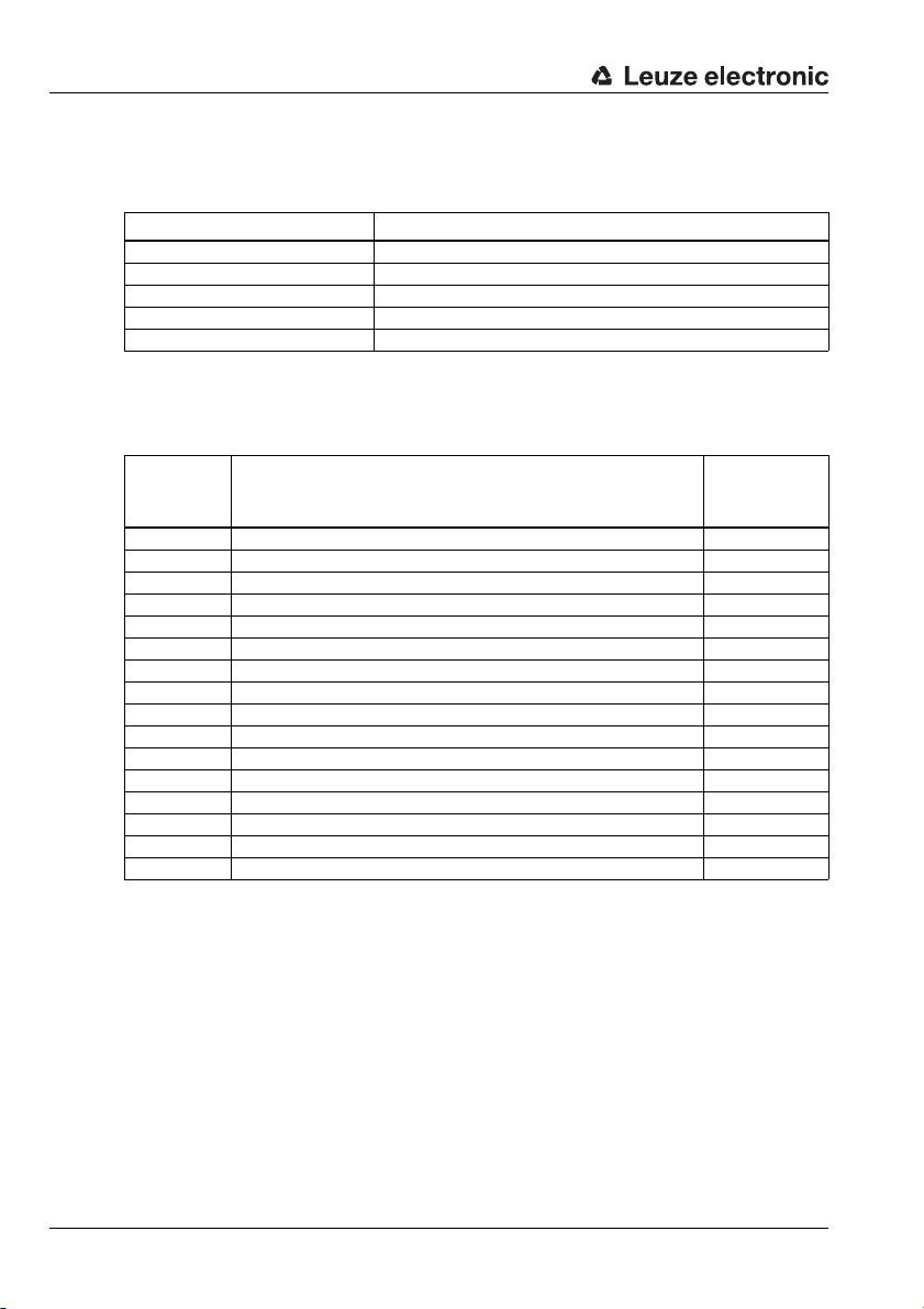
Specifications for Leuze end devices
16.4 Bar code reader BCL 300i, BCL 500i, BCL 600i (S4 switch position 4)
Specifications for the serial interface
Default parameter BCL 300i, BCL 500i, BCL 600i
Baud rate 9600
Data mode 8N1
Handshake no
Protocol framing protocol without acknowledgment
Frame <STX> <Data> <CR> <LF>
Specifications for Command mode
To activate the Command mode, bit 0 must be set to 1 in control byte 0.
For further information, see chapter 11.1.3 "Command mode", figure 11.2.
Control bit Meaning Corresponds to
serial command
(ASCII)
0 Version query v
1 Activation / deactivation reading gate + / 2 Reference code teach-in activation / deactivation RT+ / RT3
4 Autom. configuration of reading task activation / deact. CA+ / CA5 Switching output 1 activation OA1
6 Switching output 2 activation OA2
7 Switching output 1 deactivation OD1
8 Switching output 2 deactivation OD2
9
10
11
12
13 Parameter - difference to default parameter set PD20
14 Reset parameters to default values PC20
15 Device restart H
Recommended settings
• Input data: 8 bytes
Use of the Collective mode for codes with a number of digits > 4.
• Output data: 8 bytes
84 MA 235i Leuze electronic
Page 87

Specifications for Leuze end devices
16.5 Bar code reader BCL 90, BCL 900i (S4 switch position 5)
Specifications for the serial interface
Default parameter BCL 90, BCL 900i
Baud rate 9600
Data mode 8N1
Handshake no
Protocol framing protocol without acknowledgment
Frame <STX> <Data> <CR> <LF>
Specifications for Command mode
To activate the Command mode, bit 0 must be set to 1 in control byte 0.
For further information, see chapter 11.1.3 "Command mode", figure 11.2.
Control bit Meaning Corresponds to
0 Version query v
1 Activation / deactivation reading gate + / 2 Configuration mode 11
3 Alignment mode 12
4 Read operation 13
5
6
7
8
9
10
11
12
13
14 Reset parameters to default values PC20
15 Device restart H
serial command
(ASCII)
TNT 35/7-24V
Recommended settings
• Input data: 8 bytes
Use of the Collective mode for codes with a number of digits > 4.
• Output data: 8 bytes
Notice!
When using the command mode, make sure that 00H is shown in the data range; otherwise
the device only performs one alignment cycle.
Leuze electronic MA 235i 85
Page 88

Specifications for Leuze end devices
16.6 LSIS 122, LSIS 222 (S4 switch position 6)
Specifications for the serial interface
Default parameter LSIS 122, LSIS 222
Baud rate 9600
Data mode 8N1
Handshake no
Protocol framing protocol without acknowledgment
Frame <STX> <Data> <CR> <LF>
Specifications for Command mode
To activate the Command mode, bit 0 must be set to 1 in control byte 0.
For further information, see chapter 11.1.3 "Command mode", figure 11.2.
Control bit Meaning Corresponds to
0 Version query i
1 Activation/Deactivation of reading gate: 12h/14h (LSIS 122 only)<DC2> / <DC4>
2 Activation of reading gate (LSIS 222 only) <SYN>T<CR>
3 Deactivation of reading gate (LSIS 222 only) <SYN>U<CR>
4
5
6
7
8
9
10
11
12
13
14
15
serial command
(ASCII)
Recommended settings
• Input data: 8 bytes
Use of the Collective mode for codes with a number of digits > 4.
• Output data: 8 bytes
86 MA 235i Leuze electronic
Page 89

Specifications for Leuze end devices
16.7 LSIS 4x2i, DCR 202i (S4 switch position 7)
Specifications for the serial interface
Default parameter LSIS 4x2i, DCR 202i
Baud rate 9600
Data mode 8N1
Handshake no
Protocol framing protocol without acknowledgment
Frame <STX> <Data> <CR> <LF>
Specifications for Command mode
To activate the Command mode, bit 0 must be set to 1 in control byte 0.
For further information, see chapter 11.1.3 "Command mode", figure 11.2.
Control bit Meaning Corresponds to
0 Version query v
1 Image acquisition trigger +
2
3
4
5
6
7
8
9
10
11
12
13
14
15
serial command
(ASCII)
TNT 35/7-24V
Recommended settings
• Input data: 8 bytes
Use of the Collective mode for codes with a number of digits > 4.
• Output data: 8 bytes
Leuze electronic MA 235i 87
Page 90
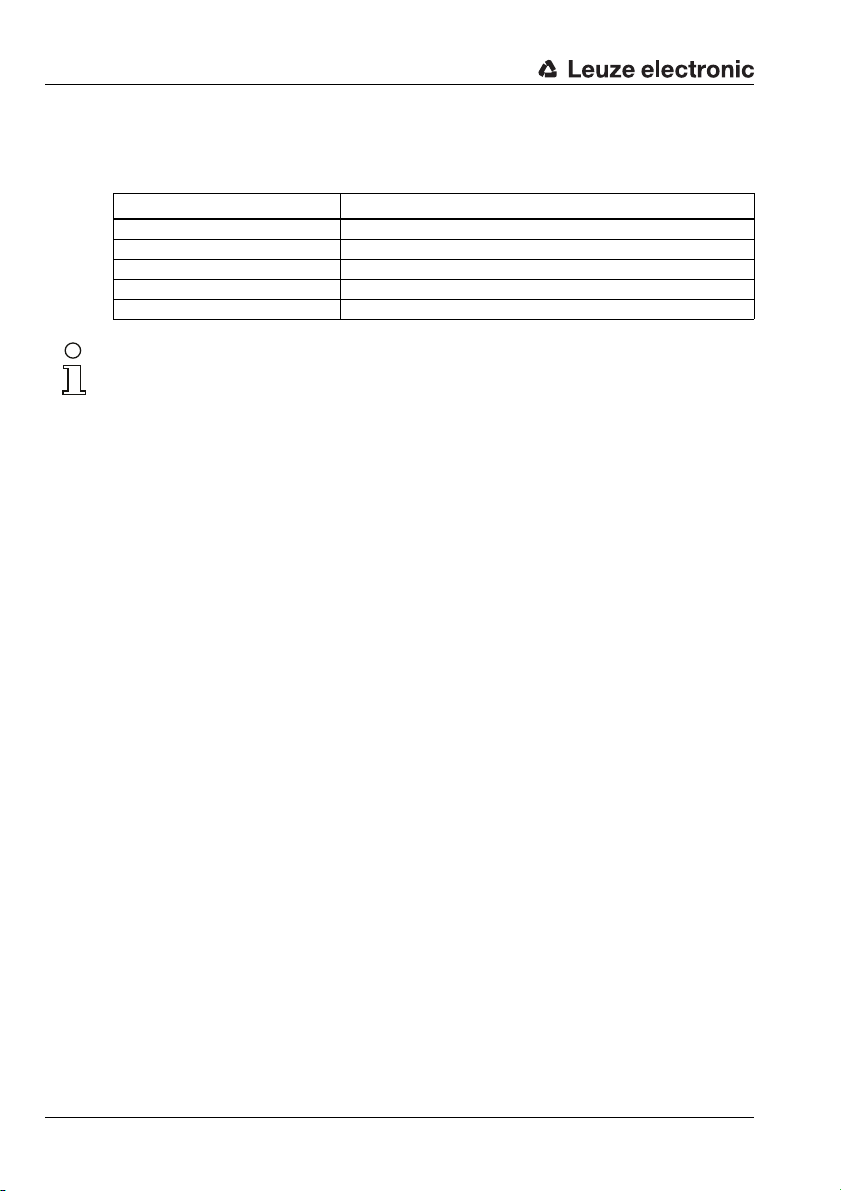
Specifications for Leuze end devices
16.8 Hand-held scanner (S4 switch position 8)
Specifications for the serial interface
Default parameter Hand-held scanner
Baud rate 9600
Data mode 8N1
Handshake no
Protocol framing protocol without acknowledgment
Frame <Data> <CR> <LF>
Notice!
Command mode cannot be used with hand-held scanners.
Recommended settings
• Input data: 8 bytes
Use of the Collective mode for codes with a number of digits > 4.
• Output data: none
88 MA 235i Leuze electronic
Page 91

Specifications for Leuze end devices
16.9 RFI, RFM, RFU RFID readers (S4 switch position 9)
Specifications for the serial interface
Default parameter RFM 12,RFM 32 and RFM 62
RFI 32
RFU (via IMRFU)
Baud rate 9600
Data mode 8N1
Handshake no
Protocol framing protocol without acknowledgment
Frame <STX> <Data> <CR> <LF>
Specifications for Command mode
To activate the Command mode, bit 0 must be set to 1 in control byte 0.
For further information, see chapter 11.1.3 "Command mode", figure 11.2.
Control bit Meaning Corresponds to
0 Version query v
1 Activation / deactivation reading gate + / 2
3
4
5
6
7
8
9
10
11
12
13
14 Reset parameters to default values R
15 Device restart H
1) Not for IMRFU/RFU
serial command
(ASCII)
1)
1)
TNT 35/7-24V
Recommended settings
• Input data: 8 bytes
Use of the Collective mode for codes with a number of digits > 4.
• Output data: 8 bytes
The RFID devices expect the telegrams / data in HEX format.
Leuze electronic MA 235i 89
Page 92

Specifications for Leuze end devices
16.10 BPS 8 bar code positioning system (S4 switch position A)
Specifications for the serial interface
Default parameter BPS 8
Baud rate 57600
Data mode 8N1
Handshake no
Protocol binary protocol without acknowledgment
Frame <Data>
Specifications for Command mode
To activate the Command mode, bit 0 must be set to 1 in control byte 0.
For further information, see chapter 11.1.3 "Command mode", figure 11.2.
Control bit Meaning Corresponds to serial
command (HEX)
byte 1 byte 2
0 Request diagnostic info 01 01
1 Request marker info 02 02
2 Request SLEEP mode 04 04
3 Request position info 08 08
4 Request individual measurement 10 10
5
6
7
8
9
10
11
12
13
14
15
Recommended settings
• Input data: 8 bytes
• Output data: 8 bytes
In this switch position, the MA automatically sends a position request to the BPS 8 every
10ms until another command comes via the control. Automatic request only restarts when
a new position request is sent by the PLC or when the MA is restarted.
90 MA 235i Leuze electronic
Page 93
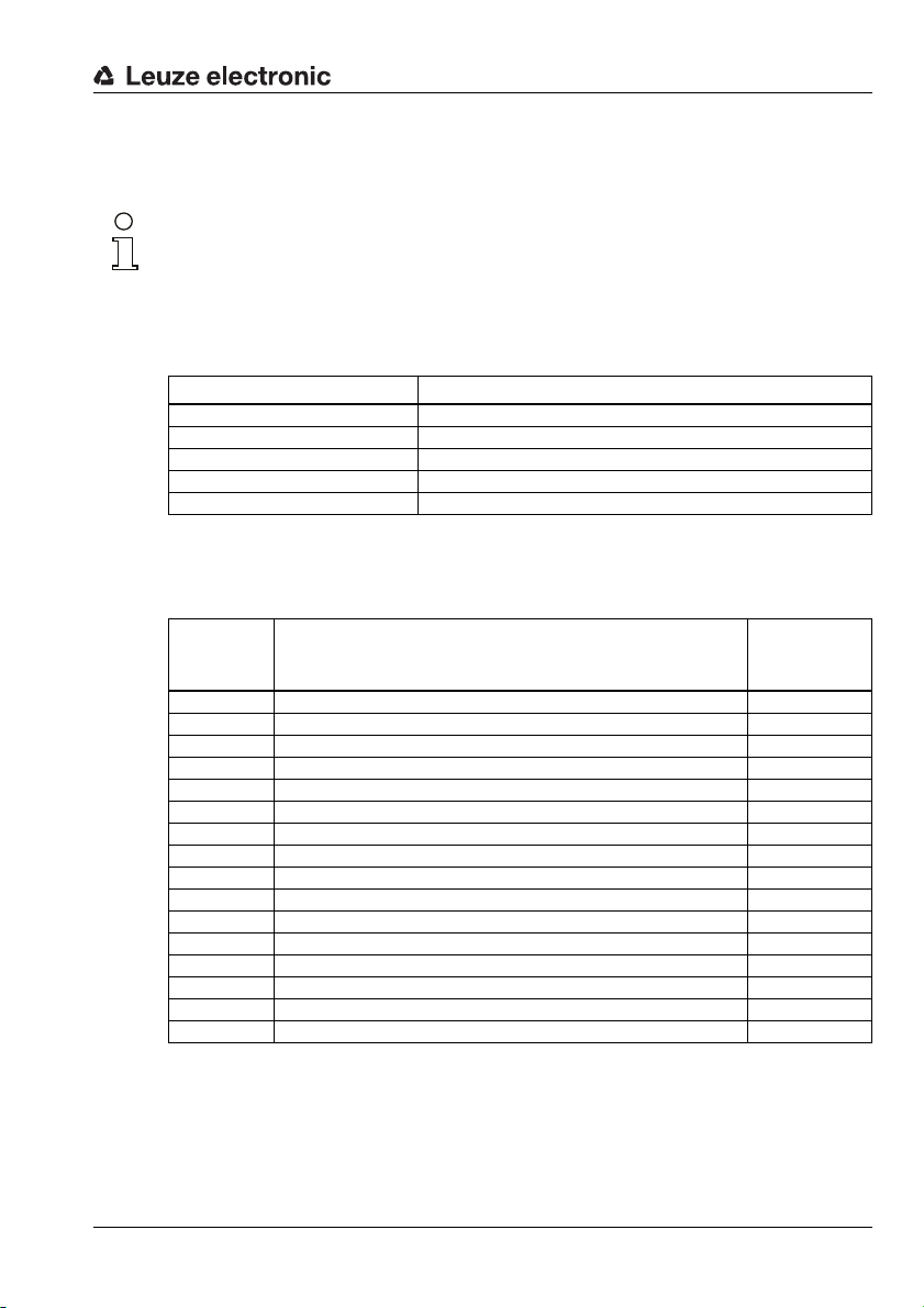
Specifications for Leuze end devices
16.11 BPS 300i bar code positioning system, ODSL xx optical distance sensors with RS 232 interface (S4 switch position B)
Notice!
In this switch position, 6-byte data (fixed) is always expected by the device. This is why a
quick telegram sequence can be transmitted reliably even without a data frame.
BPS 300i
Specifications for the serial interface
Default parameter BPS 300i
Baud rate 38400
Data mode 8N1
Handshake no
Protocol binary protocol without acknowledgment
Frame <Data>
Specifications for Command mode
To activate the Command mode, bit 0 must be set to 1 in control byte 0.
For further information, see chapter 11.1.3 "Command mode", figure 11.2.
Control bit Meaning Corresponds to
serial command
(ASCII)
0 Transmit individual position value = single shot C0F131
1 Cyclically transmit position values C0F232
2 Stop cyclical transmission C0F333
3 Laser diode on C0F434
4 Laser diode off C0F535
5 Transmit single speed value C0F636
6 Cyclically transmit speed values C0F737
7 Transmit single position and speed value C0F838
8 Cyclically transmit position and speed values C0F939
9 Transmit marker information C0FA3A
10 Not used / reserved
11 Transmit diagnostic information C0FC3C
12 Activate standby C0FD3D
13
14
15
Recommended settings
• Input data: 8 bytes
Use of the Collective mode for codes with a number of digits > 4.
• Output data: 8 bytes
Leuze electronic MA 235i 91
TNT 35/7-24V
Page 94

Specifications for Leuze end devices
ODSL 9, ODSL 30 and ODSL 96B
Notice!
The default settings of the ODS serial interface have to be adjusted! Further information on
configuration of the interface can be found in the technical description of the corresponding
device.
Specifications for the serial interface
Default parameter ODSL xx
Baud rate 38400
Data mode 8N1
Handshake no
Protocol ASCII transmission, 5-digit measurement value
Frame <Data>
Specifications for Command mode
Command mode cannot be used with the ODSL 9, ODSL 30 and ODSL 96B.
The ODSL 9/96B is to be operated in the "Precision" measure mode. The mode is set
through the display menu via Application -> Measure mode -> Precision. You can find
more details on this in the technical description.
92 MA 235i Leuze electronic
Page 95
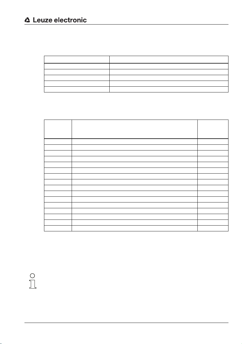
Specifications for Leuze end devices
16.12 Modular interfacing unit MA 3x (S4 switch position C)
Specifications for the serial interface
Default parameter MA 3x
Baud rate 9600
Data mode 8N1
Handshake no
Protocol framing protocol without acknowledgment
Frame <STX> <Data> <CR> <LF>
Specifications for Command mode
To activate the Command mode, bit 0 must be set to 1 in control byte 0.
For further information, see chapter 11.1.3 "Command mode", figure 11.2.
Control bit Meaning Corresponds to
0 Version query v
1
2
3
4
5
6
7
8
9
10
11
12
13
14 Reset parameters to default values PC20
15 Device restart H
serial command (ASCII)
TNT 35/7-24V
Recommended settings
• Input data: 8 bytes
Use of the Collective mode for codes with a number of digits > 4.
• Output data: 8 bytes
Notice!
In this switch position, the address of the multiNet slave is also transmitted in the first two
bytes of the data range!
Leuze electronic MA 235i 93
Page 96

Specifications for Leuze end devices
16.13 Resetting the parameters (S4 switch position F)
To reset all parameters of the MA that can be configured with software (such as baud rate,
IP address, dependent on type) to the factory settings, do the following:
Set device switch S4 to F in a voltage free state.
Switch the voltage on and wait until it is ready for operation.
If necessary, switch the voltage off to prepare for commissioning.
Set service switch S10 to the "RUN" position.
94 MA 235i Leuze electronic
Page 97
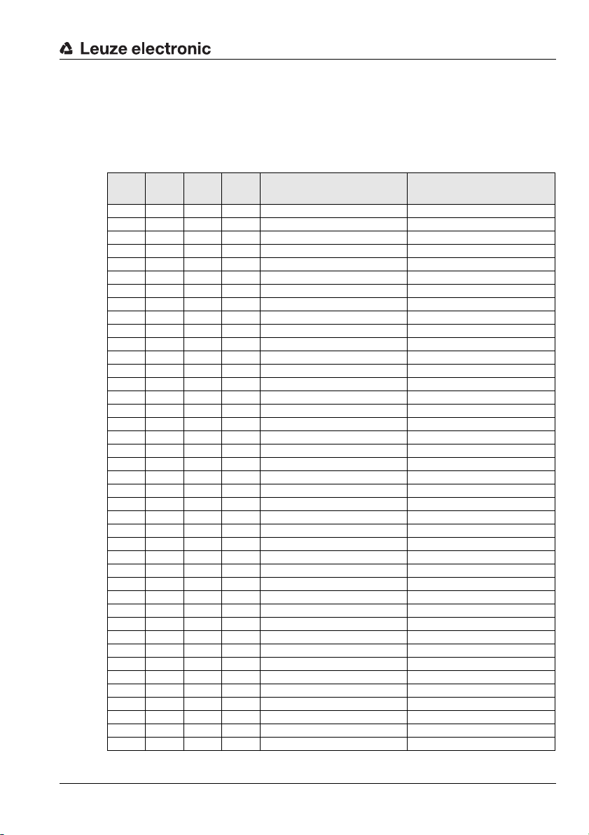
17 Appendix
17.1 ASCII Table
HEX DEC CTRL ABB DESIGNATION MEANING
00 0 ^@ NUL NULL Zero
01 1 ^A SOH START OF HEADING Start of heading
02 2 ^B STX START OF TEXT Start of text characters
03 3 ^C ETX END OF TEXT Last character of text
04 4 ^D EOT END OF TRANSMISSION End of transmission
05 5 ^E ENQ ENQUIRY Request to transmit data
06 6 ^F ACK ACKNOWLEDGE Positive acknowledgment
07 7 ^G BEL BELL Bell signal
08 8 ^H BS BACKSPACE Backspace
09 9 ^I HT HORIZONTAL TABULATOR Horizontal tabulator
0A 10 ^J LF LINE FEED Line feed
0B 11 ^K VT VERTICAL TABULATOR Vertical tabulator
0C 12 ^L FF FORM FEED Form feed
0D 13 ^M CR CARRIAGE RETURN Carriage return
0E 14 ^N SO SHIFT OUT Shift out
0F 15 ^O SI SHIFT IN Shift in
10 16 ^P DLE DATA LINK ESCAPE Data link escape
11 17 ^Q DC1 DEVICE CONTROL 1 (X-ON) Device control character 1
12 18 ^R DC2 DEVICE CONTROL 2 (TAPE) Device control character 2
13 19 ^S DC3 DEVICE CONTROL 3 (X-OFF) Device control character 3
14 20 ^T DC4 DEVICE CONTROL 4 Device control character 4
15 21 ^U NAK NEGATIVE (/Tape) ACKNOWLEDGE Negative acknowledge
16 22 ^V SYN SYNCHRONOUS IDLE Synchronization
17 23 ^W ETB END OF TRANSMISSION BLOCK End of data transmission block
18 24 ^X CAN CANCEL Invalid
19 25 ^Y EM END OF MEDIUM End of medium
1A 26 ^Z SUB SUBSTITUTE Substitution
1B 27 ^[ ESC ESCAPE Escape
1C 28 ^\ FS FILE SEPARATOR File separator
1D 29 ^] GS GROUP SEPARATOR Group separator
1E 30 ^^ RS RECORD SEPARATOR Record separator
1F 31 ^_ US UNIT SEPARATOR Unit separator
20 32 SP SPACE Space
21 33 ! EXCLAMATION POINT Exclamation point
22 34 " QUOTATION MARK Quotation mark
23 35 # NUMBER SIGN Number sign
24 36 $ DOLLAR SIGN Dollar sign
25 37 % PERCENT SIGN Percent sign
26 38 & AMPERSAND Ampersand
27 39 ' APOSTROPHE Apostrophe
28 40 ( OPENING PARENTHESIS Opening parenthesis
Appendix
TNT 35/7-24V
Leuze electronic MA 235i 95
Page 98

Appendix
HEX DEC CTRL ABB DESIGNATION MEANING
29 41 ) CLOSING PARENTHESIS Closing parenthesis
2A 42 * ASTERISK Asterisk
2B 43 + PLUS Plus sign
2C 44 , COMMA Comma
2D 45 - HYPHEN (MINUS) Hyphen (minus)
2E 46 . PERIOD (DECIMAL) Period (decimal)
2F 47 / SLANT Slant
30 48 0
31 49 1
32 50 2
33 51 3
34 52 4
35 53 5
36 54 6
37 55 7
38 56 8
39 57 9
3A 58 : COLON Colon
3B 59 ; SEMICOLON Semicolon
3C 60 < LESS THAN Less than
3D 61 = EQUALS Equals
3E 62 > GREATER THAN Greater than
3F 63 ? QUESTION MARK Question mark
40 64 @ COMMERCIAL AT Commercial AT
41 65 A
42 66 B
43 67 C
44 68 D
45 69 E
46 70 F
47 71 G
48 72 H
49 73 I
4A 74 J
4B 75 K
4C 76 L
4D 77 M
4E 78 N
4F 79 O
50 80 P
51 81 Q
52 82 R
53 83 S
54 84 T
55 85 U
56 86 V
57 87 W
58 88 X
96 MA 235i Leuze electronic
Page 99

HEX DEC CTRL ABB DESIGNATION MEANING
59 89 Y
5A 90 Z
5B 91 [ OPENING BRACKET Opening bracket
5C 92 \ REVERSE SLANT Reverse slant
5D 93 ] CLOSING BRACKET Closing bracket
5E 94 ^ CIRCUMFLEX Circumflex
5F 95 _ UNDERSCORE Underscore
60 96 ‘ GRAVE ACCENT Grave accent
61 97 a
62 98 b
63 99 c
64 100 d
65 101 e
66 102 f
67 103 g
68 104 h
69 105 i
6A 106 j
6B 107 k
6C 108 l
6D 109 m
6E 110 n
6F 111 o
70 112 p
71 113 q
72 114 r
73 115 s
74 116 t
75 117 u
76 118 v
77 119 w
78 120 x
79 121 y
7A 122 z
7B 123 { OPENING BRACE Opening brace
7C 124 | VERTICAL LINE Vertical line
7D 125 } CLOSING BRACE Closing brace
7E 126 ~ TILDE Tilde
7F 127 DEL DELETE (RUBOUT) Delete
Appendix
TNT 35/7-24V
Leuze electronic MA 235i 97
Page 100

Index
A
Accessories . . . . . . . . . . . . . . . . . . . . . . . . . 74
Bus connection cables
Cables for Leuze ident devices
Connector
Voltage supply cables
ASCII Table
C
CANopen
General information
Interface
Causes of errors
General
Interface
Collective mode
Command mode
Commissioning
Configuration
Connecting the Leuze device
PCB connectors X30 … X32
Connections
PWR IN
PWR OUT switching input/output
Control bytes
D
Declaration of Conformity . . . . . . . . . . . . . . . 5
Definition of terms
Description of functions
Device description
Device interface RS 232
Diagnosis
Dimensioned drawings
Disassembling
Disposing
E
Electrical connection . . . . . . . . . . . . . . . . . . 10
Connecting the Leuze device
Power supply and bus cable
Safety notices
F
Fast commissioning . . . . . . . . . . . . . . . . . . . 10
Fieldbus systems
. . . . . . . . . . . . . . . . . . . . . . . . 74
. . . . . . . . . . . . . . . . . . . . . . . . . 95
. . . . . . . . . . . . . . . . . . . . . . . . . 32
. . . . . . . . . . . . . . . . . . . . . . . . . . 72
. . . . . . . . . . . . . . . . . . . . . . . . . 73
. . . . . . . . . . . . . . . . . . . . . . 14
. . . . . . . . . . . . . . . . . . 14, 56
. . . . . . . . . . . . . . . . . . . . . . 58
. . . . . . . . . . . . . . . . . . . . . 41, 58
. . . . . . . . . . . . . . . . . . . . . . . . . . 28
. . . . . . . . . . . . . . . . . . . . . . . . 48
. . . . . . . . . . . . . . . . . . . . . . . . . . . 72
. . . . . . . . . . . . . . . . . . . . . . . 79
. . . . . . . . . . . . . . . . . . . . . . . . . . . 79
. . . . . . . . . . . . . . . . . . . . . 27
. . . . . . . . . . . . . . . . . . . . . 17
. . . . . . . . . . . . . . 76
. . . . . . . 78
. . . . . . . . . . . . . . 75
. . . . . . . . . . . . . . . . 17
. . . . . . . . . . . 11
. . . . . . . . . 38
. . . . . 30
. . . . . . . . . . . . . . . . . . . . . 7
. . . . . . . . . . . . . . . . . 6
. . . . . . . . . . . . . . . . . . . . 14
. . . . . . . . . . . . . . . 32
. . . . . . . . . . . . . . . . 22
. . . . . . . . . 11
. . . . . . 13, 60
I
Input byte 0
Buffer overflow
Data exist
Data loss
New data
Next block ready to transmit
Service mode active
Write-Acknowledge
Input byte 1
Data length code
Interface
CANopen
L
LED status indicators . . . . . . . . . . . . . . . . . . 34
Leuze device
2D-code reader
DCR 202i
LSIS 122
LSIS 222
LSIS 4x2i
Bar code positioning system (BPS)
BPS 300i
BPS 8
Bar code reader (BCL)
BCL 22
BCL 300i
BCL 500i
BCL 600i
BCL 8
BCL 90
BCL 900i
Hand-held scanner
Optical distance sensor (ODSL)
RFID read-write devices (RFM/RFI …)
RFM 12, 32 and 62
Setting the read parameters
Specific feature for hand-held scanners
Specifications for Command mode
Specifications for the serial interface
M
Maintenance . . . . . . . . . . . . . . . . . . . . . . . . . 79
Mounting
Device arrangement, selecting a mounting
location
. . . . . . . . . . . . . . . . . . . . 47
. . . . . . . . . . . . . . . . . . . . . . . . .46
. . . . . . . . . . . . . . . . . . . . . . . . . 47
. . . . . . . . . . . . . . . . . . . . . . . . . 48
. . . . . . . . . . 47
. . . . . . . . . . . . . . . . 46
. . . . . . . . . . . . . . . . . 46
. . . . . . . . . . . . . . . . . . . 48
. . . . . . . . . . . . . . . . . . . . . . . . . 32
. . . . . . . . . . . . . . . . . . . . . .87
. . . . . . . . . . . . . . . . . . . . . . . 86
. . . . . . . . . . . . . . . . . . . . . . . 86
. . . . . . . . . . . . . . . . . . . . . . 87
. . . . . . . . . . . . . . . . . . . . . . .91
. . . . . . . . . . . . . . . . . . . . . . . . . 90
. . . . . . . . . . . . . . . . . . . . . . . . 83
. . . . . . . . . . . . . . . . . . . . . . . 84
. . . . . . . . . . . . . . . . . . . . . . . 84
. . . . . . . . . . . . . . . . . . . . . . . 84
. . . . . . . . . . . . . . . . . . . . . . . . . 82
. . . . . . . . . . . . . . . . . . . . . . . . 85
. . . . . . . . . . . . . . . . . . . . . . . 85
. . . . . . . . . . . . . . . . . 88
. . . . . . . 91
. . . . . . . . . . . . . . . 89
. . . . . . . . . . 69
70
. . . . . 80
. . . 80
. . . . . . . . . . . . . . . . . . . . . . 10, 26
98 MA 235i Leuze electronic
 Loading...