

Page 1

MA 208i
Modular interfacing unit for Leuze Ident and
RS 232 devices on Ethernet TCP/IP
en 02–2012/04 50113024
TECHNICAL DESCRIPTION
Page 2

Condelectric S.A.
Tel. Int. + 54 1148 361053
Fax Int. + 54 1148 361053
Tel. Int. + 43 732 7646-0
Fax Int. + 43 732 7646-785
Balluff-Leuze Pty. Ltd.
Tel. Int. + 61 3 9720 4100
Fax Int. + 61 3 9738 2677
Leuze electronic nv/ sa
Tel. Int. + 32 2253 16-00
Fax Int. + 32 2253 15-36
ATICS
Tel. Int. + 359 2 847 6244
Fax Int. + 359 2 847 6244
Leuze electronic Ltda.
Tel. Int. + 55 11 5180-6130
Fax Int. + 55 11 5180-6141
Leuze electronic AG
Tel. Int. + 41 41 784 5656
Fax Int. + 41 41 784 5657
Imp. Tec. Vignola S.A.I.C.
Tel. Int. + 56 3235 11-11
Fax Int. + 56 3235 11-28
Leuze electronic Trading
(Shenzhen) Co. Ltd.
Tel. Int. + 86 755 862 64909
Fax Int. + 86 755 862 64901
Componentes Electronicas Ltda.
Tel. Int. + 57 4 3511049
Fax Int. + 57 4 3511019
Schmachtl CZ s.r.o.
Tel. Int. + 420 244 0015-00
Fax Int. + 420 244 9107-00
Leuze electronic Scandinavia ApS
Tel. Int. + 45 48 173200
SKS-automaatio Oy
Tel. Int. + 358 20 764-61
Fax Int. + 358 20 764-6820
Leuze electronic Sarl.
Tel. Int. + 33 160 0512-20
Fax Int. + 33 160 0503-65
Leuze electronic Ltd.
Tel. Int. + 44 14 8040 85-00
Fax Int. + 44 14 8040 38-08
UTECO A.B.E.E.
Tel. Int. + 30 211 1206 900
Fax Int. + 30 211 1206 999
ALL IMPEX 2001
Tel. Int. + 7 495 9213012
Fax Int. + 7 495 6462092
Leuze electronic Scandinavia ApS
Ingermark (M) SDN.BHD
Tel. Int. + 60 360 3427-88
Fax Int. + 60 360 3421-88
Movitren S.A.
Tel. Int. + 52 81 8371 8616
Fax Int. + 52 81 8371 8588
Leuze electronic BV
Tel. Int. + 31 418 65 35-44
Fax Int. + 31 418 65 38-08
LA2P, Lda.
Tel. Int. + 351 21 4 447070
Fax Int. + 351 21 4 447075
Balluff Sp. z o. o.
Tel. Int. + 48 71 338 49 29
Fax Int. + 48 71 338 49 30
O`BOYLE s.r.l
Tel. Int. + 40 2 56201346
Fax Int. + 40 2 56221036
Elteco A/S
Tel. Int. + 47 35 56 20-70
Fax Int. + 47 35 56 20-99
Great Cofue Technology Co., Ltd.
Tel. Int. + 886 2 2983 80-77
Fax Int. + 886 2 2985 33-73
Countapulse Controls (PTY.) Ltd.
11/2011
Tel. Int. + 27 116 1575-56
Fax Int. + 27 116 1575-13
Schmachtl SK s.r.o.
Tel. Int. + 421 2 58275600
Fax Int. + 421 2 58275601
Tipteh d.o.o.
Tel. Int. + 386 1200 51-50
Fax Int. + 386 1200 51-51
Industrial Elect
rical Co. Ltd.
Tel .
Int. + 66 2 642 6700
Fax Int. + 66 2 642 4250
Leuze electronic San.ve Tic.Ltd.Sti.
Tel. Int. + 90 216 456 6704
Fax Int. + 90 216 456 3650
Balluff Asia Pte Ltd
Tel. Int. + 65 6252 43-84
Fax Int. + 65 6252 90-60
Leuze electronic, Inc.
Tel. Int. + 1 248 486-4466
Fax Int. + 1 248 486-6699
SV Altera OOO
Tel. Int. + 38 044 4961888
Fax Int. + 38 044 4961818
C. Illies & Co., Ltd.
Tel. Int. + 81 3 3443 4143
Fax Int. + 81 3 3443 4118
Profa-Tech Ltd.
Tel. Int. + 254 20 828095/6
Fax Int. + 254 20 828129
Leuze electronic Co., Ltd.
Tel. Int. + 82 31 382822
8 Tel. Int. +46 380-490951
Fax Int. + 82 31 3828522
Leuze electronic S.A.
Tel. Int. + 34 93 4097900
Fax Int. + 34 93 49035820
Schmachtl GmbH
SABROW HI-TECH E. & A. LTD.
Tel. Int. + 234 80333 86366
Fax Int. + 234 80333 84463518
Tipteh d.o.o. Beograd
Tel. Int. + 381 11 3131 057
Fax Int. + 381 11 3018 326
Tipteh d.o.o. Skopje
Tel. Int. + 389 70 399 474
Fax Int. + 389 23 174 197
Leuze electronic S.r.l.
Tel. Int. + 39 02 26 1106-43
Fax Int. + 39 02 26 1106-40
Kvalix Automatika Kft.
Tel. Int. + 36 1 272 2242
Fax Int. + 36 1 272 2244
P.T. Yabestindo Mitra Utama
Tel. Int. + 62 21 92861859
Fax Int. + 62 21 6451044
Galoz electronics Ltd.
Tel. Int. + 972 3 9023456
Fax Int. + 972 3 9021990
M + V Marketing Sales Pvt Ltd.
Tel. Int. + 91 124 4121623
Fax Int. + 91 124 434233
Sensortech Company
Tel. Int. + 852 26510188
Fax Int. + 852 26510388
Tipteh Zagreb d.o.o.
Tel. Int. + 385 1 381 6574
Fax Int. + 385 1 381 6577
Leuze electronic GmbH + Co. KG
P.O. Box 1111, D- 73277 Owen
Tel. +49(0) 7021/ 57 3-0,
Fax +49(0 )7021 / 573-199
info@leuze.dew.leuze.com
Sales Region East
Phone 035027/629-106
Fax 035027/629-107
Postal code areas
01000-19999
39000-39999
98000-99999
Sales Region North
Phone 07021/573-306
Fax 07021/9850950
Postal code areas
20000-38999
40000-65999
97000-97999
Sales Region South
Phone 07021/573-307
Fax 07021/9850911
Postal code areas
66000-96999
Sales and Service
Worldwide
AT (Austria)
AR (Argentina)
AU + NZ (Australia + New Zealand)
BE (Belgium)
BG (Bulgaria)
BR (Brasil)
CH (Switzerland)
CO (Colombia)
CZ (Czech Republic)
CL (Chile)
CN (China)
DK (Denmark)
FI (Finland)
GB (United Kingdom)
GR (Greece)
FR (France)
RU (Russian Federation)
SE (Sweden)
MY (Malaysia)
MX (Mexico)
NL (Netherlands)
PT (Portugal)
PL (Poland)
RO (Romania)
NO (Norway)
TW (Taiwan)
ZA (South Africa)
SK (Slowakia)
SI (Slovenia)
TH (Thailand)
TR (Turkey)
SG + PH (Singapore +
Philippines)
US + CA (United States +
Canada)
UA (Ukraine)
JP (Japan)
KR (South Korea)
ES (Spain)
Germany
KE (Kenia)
NG (Nigeria)
RS (Republic of Serbia)
MK (Macedonia)
IT (Italy)
HU (Hungary)
ID (Indonesia)
IL (Israel)
IN (India)
HK (Hong Kong)
HR (Croatia)
© All rights reserved, especially the right of reproduction and translation. Copying
or reproduction in any form require the written consent of the manufacturer.
Product names are used without a guarantee of free usage.
Changes reflecting technical improvements may be made.
Page 3

Table of contents
1 General information . . . . . . . . . . . . . . . . . . . . . . . . . . . . . . . . . . . . 5
1.1 Explanation of symbols . . . . . . . . . . . . . . . . . . . . . . . . . . . . . . . . . . . . . . . . . . . . . . . . . . . 5
1.2 Declaration of Conformity . . . . . . . . . . . . . . . . . . . . . . . . . . . . . . . . . . . . . . . . . . . . . . . . . 5
1.3 Description of functions . . . . . . . . . . . . . . . . . . . . . . . . . . . . . . . . . . . . . . . . . . . . . . . . . . 6
1.4 Definition of terms . . . . . . . . . . . . . . . . . . . . . . . . . . . . . . . . . . . . . . . . . . . . . . . . . . . . . . . 7
2 Safety notices. . . . . . . . . . . . . . . . . . . . . . . . . . . . . . . . . . . . . . . . . 8
2.1 General safety notices . . . . . . . . . . . . . . . . . . . . . . . . . . . . . . . . . . . . . . . . . . . . . . . . . . . . 8
2.2 Safety standards . . . . . . . . . . . . . . . . . . . . . . . . . . . . . . . . . . . . . . . . . . . . . . . . . . . . . . . . 8
2.3 Intended use . . . . . . . . . . . . . . . . . . . . . . . . . . . . . . . . . . . . . . . . . . . . . . . . . . . . . . . . . . . 8
2.4 Working safely . . . . . . . . . . . . . . . . . . . . . . . . . . . . . . . . . . . . . . . . . . . . . . . . . . . . . . . . . . 9
3 Fast commissioning / operating principle . . . . . . . . . . . . . . . . . . . 10
3.1 Mounting . . . . . . . . . . . . . . . . . . . . . . . . . . . . . . . . . . . . . . . . . . . . . . . . . . . . . . . . . . . . . 10
3.2 Device arrangement and selection of the mounting location . . . . . . . . . . . . . . . . . . . . 10
3.3 Electrical connection . . . . . . . . . . . . . . . . . . . . . . . . . . . . . . . . . . . . . . . . . . . . . . . . . . . . 10
3.3.1 Connecting the Leuze device . . . . . . . . . . . . . . . . . . . . . . . . . . . . . . . . . . . . . . . . . . . . . . 11
3.3.2 Connecting the power supply and the bus cable . . . . . . . . . . . . . . . . . . . . . . . . . . . . . . . 11
3.4 Starting the device. . . . . . . . . . . . . . . . . . . . . . . . . . . . . . . . . . . . . . . . . . . . . . . . . . . . . . 11
3.5 MA 208i on Ethernet . . . . . . . . . . . . . . . . . . . . . . . . . . . . . . . . . . . . . . . . . . . . . . . . . . . . 12
3.5.1 Manually setting the IP address . . . . . . . . . . . . . . . . . . . . . . . . . . . . . . . . . . . . . . . . . . . . 12
3.5.2 Ethernet host communication. . . . . . . . . . . . . . . . . . . . . . . . . . . . . . . . . . . . . . . . . . . . . . 13
3.5.3 TCP/IP. . . . . . . . . . . . . . . . . . . . . . . . . . . . . . . . . . . . . . . . . . . . . . . . . . . . . . . . . . . . . . . . 14
3.5.4 UDP. . . . . . . . . . . . . . . . . . . . . . . . . . . . . . . . . . . . . . . . . . . . . . . . . . . . . . . . . . . . . . . . . . 14
4 Device description . . . . . . . . . . . . . . . . . . . . . . . . . . . . . . . . . . . . 15
4.1 General Information to the connector units . . . . . . . . . . . . . . . . . . . . . . . . . . . . . . . . . . 15
4.2 Characteristics of the connector units . . . . . . . . . . . . . . . . . . . . . . . . . . . . . . . . . . . . . . 15
4.3 Device construction. . . . . . . . . . . . . . . . . . . . . . . . . . . . . . . . . . . . . . . . . . . . . . . . . . . . . 16
4.4 Operating modes . . . . . . . . . . . . . . . . . . . . . . . . . . . . . . . . . . . . . . . . . . . . . . . . . . . . . . . 17
4.5 Fieldbus systems . . . . . . . . . . . . . . . . . . . . . . . . . . . . . . . . . . . . . . . . . . . . . . . . . . . . . . . 18
4.5.1 Ethernet. . . . . . . . . . . . . . . . . . . . . . . . . . . . . . . . . . . . . . . . . . . . . . . . . . . . . . . . . . . . . . . 18
5 Specifications . . . . . . . . . . . . . . . . . . . . . . . . . . . . . . . . . . . . . . . . 20
5.1 General specifications . . . . . . . . . . . . . . . . . . . . . . . . . . . . . . . . . . . . . . . . . . . . . . . . . . . 20
5.2 Dimensioned drawings . . . . . . . . . . . . . . . . . . . . . . . . . . . . . . . . . . . . . . . . . . . . . . . . . . 21
5.3 Type overview . . . . . . . . . . . . . . . . . . . . . . . . . . . . . . . . . . . . . . . . . . . . . . . . . . . . . . . . . 22
Leuze electronic MA 208i 1
Page 4

Table of contents
6 Installation and mounting . . . . . . . . . . . . . . . . . . . . . . . . . . . . . . . 23
6.1 Storage, transportation . . . . . . . . . . . . . . . . . . . . . . . . . . . . . . . . . . . . . . . . . . . . . . . . . . 23
6.2 Mounting . . . . . . . . . . . . . . . . . . . . . . . . . . . . . . . . . . . . . . . . . . . . . . . . . . . . . . . . . . . . . . 24
6.3 Device arrangement . . . . . . . . . . . . . . . . . . . . . . . . . . . . . . . . . . . . . . . . . . . . . . . . . . . . . 25
6.3.1 Selecting a mounting location . . . . . . . . . . . . . . . . . . . . . . . . . . . . . . . . . . . . . . . . . . . . . . 25
6.4 Cleaning . . . . . . . . . . . . . . . . . . . . . . . . . . . . . . . . . . . . . . . . . . . . . . . . . . . . . . . . . . . . . . 25
7 Electrical connection . . . . . . . . . . . . . . . . . . . . . . . . . . . . . . . . . . 26
7.1 Safety notices for the electrical connection . . . . . . . . . . . . . . . . . . . . . . . . . . . . . . . . . . 26
7.2 Electrical connection . . . . . . . . . . . . . . . . . . . . . . . . . . . . . . . . . . . . . . . . . . . . . . . . . . . .27
7.2.1 PWR IN – voltage supply / switching input/output . . . . . . . . . . . . . . . . . . . . . . . . . . . . . . 27
7.2.2 PWR OUT switching input/output . . . . . . . . . . . . . . . . . . . . . . . . . . . . . . . . . . . . . . . . . . . 29
7.3 BUS IN . . . . . . . . . . . . . . . . . . . . . . . . . . . . . . . . . . . . . . . . . . . . . . . . . . . . . . . . . . . . . . . . 29
7.4 BUS OUT . . . . . . . . . . . . . . . . . . . . . . . . . . . . . . . . . . . . . . . . . . . . . . . . . . . . . . . . . . . . . . 30
7.5 Device interfaces . . . . . . . . . . . . . . . . . . . . . . . . . . . . . . . . . . . . . . . . . . . . . . . . . . . . . . . 31
7.5.1 RS 232 device interface (accessible after opening the device, internal) . . . . . . . . . . . . . . 31
7.5.2 Service interface (internal) . . . . . . . . . . . . . . . . . . . . . . . . . . . . . . . . . . . . . . . . . . . . . . . . . 32
7.6 Ethernet wiring . . . . . . . . . . . . . . . . . . . . . . . . . . . . . . . . . . . . . . . . . . . . . . . . . . . . . . . . . 33
7.7 Cable lengths and shielding . . . . . . . . . . . . . . . . . . . . . . . . . . . . . . . . . . . . . . . . . . . . . . . 33
8 Status displays and operational controls . . . . . . . . . . . . . . . . . . . . 34
8.1 LED status indicators . . . . . . . . . . . . . . . . . . . . . . . . . . . . . . . . . . . . . . . . . . . . . . . . . . . . 34
8.1.1 LED indicators on the circuit board . . . . . . . . . . . . . . . . . . . . . . . . . . . . . . . . . . . . . . . . . . 34
8.1.2 LED indicators on the housing . . . . . . . . . . . . . . . . . . . . . . . . . . . . . . . . . . . . . . . . . . . . 35
8.2 Internal interfaces and operational controls . . . . . . . . . . . . . . . . . . . . . . . . . . . . . . . . . .36
8.2.1 Overview of operational controls of the. . . . . . . . . . . . . . . . . . . . . . . . . . . . . . . . . . . . . . . 36
8.2.2 Connector X30 … connectors . . . . . . . . . . . . . . . . . . . . . . . . . . . . . . . . . . . . . . . . . . . . . . 38
8.2.3 RS 232 service interface – X33 . . . . . . . . . . . . . . . . . . . . . . . . . . . . . . . . . . . . . . . . . . . . . 38
8.2.4 S10 service switch. . . . . . . . . . . . . . . . . . . . . . . . . . . . . . . . . . . . . . . . . . . . . . . . . . . . . . . 38
8.2.5 Rotary switch S4 for device selection . . . . . . . . . . . . . . . . . . . . . . . . . . . . . . . . . . . . . . . . 39
9 Configuration . . . . . . . . . . . . . . . . . . . . . . . . . . . . . . . . . . . . . . . . 40
9.1 Connecting the service interface . . . . . . . . . . . . . . . . . . . . . . . . . . . . . . . . . . . . . . . . . . . 40
9.2 Reading out information in Service mode . . . . . . . . . . . . . . . . . . . . . . . . . . . . . . . . . . . . 40
10 Telegram . . . . . . . . . . . . . . . . . . . . . . . . . . . . . . . . . . . . . . . . . . . . 44
10.1 Structure of the fieldbus telegram . . . . . . . . . . . . . . . . . . . . . . . . . . . . . . . . . . . . . . . . . . 44
10.2 Description of the input bytes (status bytes). . . . . . . . . . . . . . . . . . . . . . . . . . . . . . . . . . 45
2 MA 208i Leuze electronic
Page 5

Table of contents
10.2.1 Structure and meaning of the input bytes (status bytes) . . . . . . . . . . . . . . . . . . . . . . . . . 45
10.2.2 Detailed description of the bits (input byte 0) . . . . . . . . . . . . . . . . . . . . . . . . . . . . . . . . . . 46
10.2.3 Detailed description of the bits (input byte 1) . . . . . . . . . . . . . . . . . . . . . . . . . . . . . . . . . . 46
10.3 Description of the output bytes (control bytes) . . . . . . . . . . . . . . . . . . . . . . . . . . . . . . . 47
10.3.1 Structure and meaning of the output bytes (control bytes) . . . . . . . . . . . . . . . . . . . . . . . 47
10.3.2 Detailed description of the bits (output byte 0). . . . . . . . . . . . . . . . . . . . . . . . . . . . . . . . . 48
11 Modes. . . . . . . . . . . . . . . . . . . . . . . . . . . . . . . . . . . . . . . . . . . . . . 49
11.1 Functionality of the data exchange. . . . . . . . . . . . . . . . . . . . . . . . . . . . . . . . . . . . . . . . . 49
11.1.1 Writing slave data in Collective mode (PLC -> gateway) . . . . . . . . . . . . . . . . . . . . . . . . . 49
11.1.2 Command mode . . . . . . . . . . . . . . . . . . . . . . . . . . . . . . . . . . . . . . . . . . . . . . . . . . . . . . . . 50
12 Commissioning and configuration. . . . . . . . . . . . . . . . . . . . . . . . . 52
12.1 Measures to be performed prior to the initial commissioning. . . . . . . . . . . . . . . . . . . . 52
12.2 Starting the device and setting the communication parameters . . . . . . . . . . . . . . . . . 53
12.2.1 Manually setting the IP address . . . . . . . . . . . . . . . . . . . . . . . . . . . . . . . . . . . . . . . . . . . . 53
12.2.2 Ethernet host communication. . . . . . . . . . . . . . . . . . . . . . . . . . . . . . . . . . . . . . . . . . . . . . 54
12.2.3 TCP/IP. . . . . . . . . . . . . . . . . . . . . . . . . . . . . . . . . . . . . . . . . . . . . . . . . . . . . . . . . . . . . . . . 55
12.2.4 UDP. . . . . . . . . . . . . . . . . . . . . . . . . . . . . . . . . . . . . . . . . . . . . . . . . . . . . . . . . . . . . . . . . . 55
12.3 Setting the read parameters on the Leuze device . . . . . . . . . . . . . . . . . . . . . . . . . . . . . 55
12.3.1 Specific feature for the use of hand-held scanners
(bar code and 2D devices, combi devices with RFID) . . . . . . . . . . . . . . . . . . . . . . . . . . . 57
12.3.2 Specific features in the operation of an RFM/RFI. . . . . . . . . . . . . . . . . . . . . . . . . . . . . . . 58
13 Diagnostics and troubleshooting . . . . . . . . . . . . . . . . . . . . . . . . . 59
13.1 General causes of errors . . . . . . . . . . . . . . . . . . . . . . . . . . . . . . . . . . . . . . . . . . . . . . . . . 59
13.2 Interface errors. . . . . . . . . . . . . . . . . . . . . . . . . . . . . . . . . . . . . . . . . . . . . . . . . . . . . . . . . 60
14 Type overview and accessories . . . . . . . . . . . . . . . . . . . . . . . . . . 61
14.1 Part number code . . . . . . . . . . . . . . . . . . . . . . . . . . . . . . . . . . . . . . . . . . . . . . . . . . . . . . 61
14.2 Type overview . . . . . . . . . . . . . . . . . . . . . . . . . . . . . . . . . . . . . . . . . . . . . . . . . . . . . . . . . 61
14.3 Accessory connectors . . . . . . . . . . . . . . . . . . . . . . . . . . . . . . . . . . . . . . . . . . . . . . . . . . . 61
14.4 Accessory ready-made cables for voltage supply . . . . . . . . . . . . . . . . . . . . . . . . . . . . . 62
14.4.1 Contact assignment of PWR connection cable . . . . . . . . . . . . . . . . . . . . . . . . . . . . . . . . 62
14.4.2 Specifications of the cables for voltage supply . . . . . . . . . . . . . . . . . . . . . . . . . . . . . . . . 62
14.4.3 Order codes of the cables for voltage supply. . . . . . . . . . . . . . . . . . . . . . . . . . . . . . . . . . 63
14.5 Accessory ready-made cables for bus connection . . . . . . . . . . . . . . . . . . . . . . . . . . . . 63
14.5.1 General information . . . . . . . . . . . . . . . . . . . . . . . . . . . . . . . . . . . . . . . . . . . . . . . . . . . . . 63
14.5.2 Contact assignments of M 12 Ethernet connection cable KB ET… . . . . . . . . . . . . . . . . . 63
14.5.3 Technical data of M 12 Ethernet connection cable KB ET… . . . . . . . . . . . . . . . . . . . . . . 64
Leuze electronic MA 208i 3
Page 6

Table of contents
14.5.4 Order codes of M 12 Ethernet connection cable KB ET…. . . . . . . . . . . . . . . . . . . . . . . . . 64
14.6 Accessory ready-made cables for connecting Leuze Ident devices . . . . . . . . . . . . . . . 65
14.6.1 Order codes for the device connection cables . . . . . . . . . . . . . . . . . . . . . . . . . . . . . . . . . 65
14.6.2 Contact assignment for the device connection cables . . . . . . . . . . . . . . . . . . . . . . . . . . . 65
15 Maintenance . . . . . . . . . . . . . . . . . . . . . . . . . . . . . . . . . . . . . . . . . 66
15.1 General maintenance information . . . . . . . . . . . . . . . . . . . . . . . . . . . . . . . . . . . . . . . . . . 66
15.2 Repairs, servicing . . . . . . . . . . . . . . . . . . . . . . . . . . . . . . . . . . . . . . . . . . . . . . . . . . . . . . . 66
15.3 Disassembling, packing, disposing . . . . . . . . . . . . . . . . . . . . . . . . . . . . . . . . . . . . . . . . . 66
16 Specifications for Leuze end devices . . . . . . . . . . . . . . . . . . . . . . 67
16.1 Standard setting, KONTURflex (S4 switch position 0) . . . . . . . . . . . . . . . . . . . . . . . . . . 67
16.2 Bar code reader BCL 8 (S4 switch position 1) . . . . . . . . . . . . . . . . . . . . . . . . . . . . . . . . 69
16.3 Bar code reader BCL 22 (S4 switch position 2) . . . . . . . . . . . . . . . . . . . . . . . . . . . . . . . 70
16.4 Bar code reader BCL 32 (S4 switch position 3) . . . . . . . . . . . . . . . . . . . . . . . . . . . . . . . 71
16.5 Bar code reader BCL 300i, BCL 500i (S4 switch position 4). . . . . . . . . . . . . . . . . . . . . . 72
16.6 Bar code reader BCL 90 (S4 switch position 5) . . . . . . . . . . . . . . . . . . . . . . . . . . . . . . . 73
16.7 LSIS 122 (S4 switch position 6) . . . . . . . . . . . . . . . . . . . . . . . . . . . . . . . . . . . . . . . . . . . . 74
16.8 LSIS 4x2i (S4 switch position 7) . . . . . . . . . . . . . . . . . . . . . . . . . . . . . . . . . . . . . . . . . . . . 75
16.9 Hand-held scanner (S4 switch position 8) . . . . . . . . . . . . . . . . . . . . . . . . . . . . . . . . . . . . 76
16.10 RFI, RFM, RFU RFID readers (S4 switch position 9) . . . . . . . . . . . . . . . . . . . . . . . . . . . . 77
16.11 BPS 8 bar code positioning system (S4 switch position A) . . . . . . . . . . . . . . . . . . . . . . 78
16.12 AMS distance measurement device, ODSL xx optical distance sensors
16.13 Modular interfacing unit MA 3x (S4 switch position C) . . . . . . . . . . . . . . . . . . . . . . . . . . 81
16.14 Resetting the parameters (S4 switch position F) . . . . . . . . . . . . . . . . . . . . . . . . . . . . . . 82
with RS 232 interface (S4 switch position B). . . . . . . . . . . . . . . . . . . . . . . . . . . . . . . . . .79
17 Appendix . . . . . . . . . . . . . . . . . . . . . . . . . . . . . . . . . . . . . . . . . . . . 83
17.1 ASCII Table . . . . . . . . . . . . . . . . . . . . . . . . . . . . . . . . . . . . . . . . . . . . . . . . . . . . . . . . . . . . 83
4 MA 208i Leuze electronic
Page 7

1 General information
1.1 Explanation of symbols
The symbols used in this operating manual are explained below.
Attention!
This symbol precedes text messages which must stri
this information results in injuries to persons or damage to the equipment.
Notice!
This symbol indicates text passages containing important info
1.2 Declaration of Conformity
The MA 208i modular interfacing units have been designed and manufactured in
accordance with applicable European directives and standards.
Notice!
The Declaration of Conformity for these devices can
General information
ctly be observed. Failure to comply with
rmation.
be requested from the manufacturer.
The manufacturer of the product, Leuze electronic GmbH + Co. KG in D-73277 Owen,
possesses a certified quality assurance system in accordance with ISO 9001.
Leuze electronic MA 208i 5
TNT 35/7-24V
Page 8

General information
1.3 Description of functions
The MA 208i modular interfacing unit is used to connect Leuze devices directly to the
fieldbus.
Bar code reader: BCL 8, 22, 32, 300i, 500i, 90
2D code reader: LSIS 122, LSIS 4x2i
Hand-held scanner ITxxxx, HFU/HFM
RFID read-write devices: RFM 12, 32, 62 & RFI 32, RFU 61, 81
Bar code positioning system: BPS 8
Distance measurement device: AMS 200
Optical distance sensors: ODSL 9, ODSL 30, ODSL 96B
Measuring light curtain: KONTURflex to Quattro-RSX/M12
multiNet master connection box: MA 3x
Additional RS 232 devices: scales, third-party devices
This is accomplished by transmitting the data from the DEV via an RS 232 (V.24) interface
to the MA 208
on the RS 232 interface corresponds to the Leuze standard data format (9600 bd, 8N1 and
STX, data, CR, LF).
The corresponding Leuze devices are selected using a rotary code switch on the circuit
board of the connector unit. Many additional RS 232 devices can be connected through a
universal position.
i where a module converts it into the Ethernet TCP/IP format. The data format
6MA 208i Leuze electronic
Page 9

1.4 Definition of terms
For better understanding of the explanations provided in this document, a definition of terms
follows below:
General information
• Bit designation:
The 1st bit or byte begins with count number "0" and means bit/byte 2
• Data length:
Size of a valid, continuous data packet in bytes.
• Consistent:
Data which belongs together with regard to content and which must not be separated
is referred to as consistent data. When identifying objects, it must be ensured that
the data is transmitted completely and in the correct order, otherwise the result is
falsified.
• Leuze device (DEV):
Leuze devices, e.g., bar code readers, RFID readers, VisionReader…
• Online command:
These commands refer to the respective, connected ident device and may be different depending on the device. These commands are not interpreted by the MA 208
but are instead transmitted transparently (see description of Ident device).
• CR:
Cross reference.
• Perspective of I/O data in the description:
Output data is data which is sent by the control to the MA. Input data is data which
is sent by the MA to the control.
• Tog g le b its :
Status toggle bit
Each change of state indicates that an action was performed, e.g., bit ND (new data):
each change of state indicates that new received data was transmitted to the PLC.
Control toggle bit
An action is performed on each change of state, e.g., bit SDO: on each change of
state, the registered data is sent by the PLC to the MA 208
i.
0
.
i,
TNT 35/7-24V
Leuze electronic MA 208i 7
Page 10

Safety notices
2 Safety notices
2.1 General safety notices
Documentation
All entries in this technical description must strictly be observed, in particular those in the
"Safety notices" section. Keep this technical description in a safe place. It should be
available at all times.
Safety regulations
Observe the locally applicable legal regulations and the rules of the employer's liability
insurance association.
Repair
Repairs must only be carried out by the manufacturer or an authorized representative.
2.2 Safety standards
The devices of the series MA 2xx
with the applicable safety standards. They correspond to the state of the art.
2.3 Intended use
i were developed, manufactured and tested in accordance
Attention!
The protection of personnel and the device is guaranteed only if the device is operated in a
manner corresponding to its intended use.
Areas of application
The MA 208
or 2D code readers, hand-held scanners, RFID read-write devices, etc. directly to the
fieldbus. A detailed list can be found in "Description of functions" on page 6.
8 MA 208i Leuze electronic
i modular interfacing unit is used for connecting Leuze devices such as barcode-
Page 11

2.4 Working safely
Attention!
Access to or changes on the device, except where expressly described in this operating
manual, is not authorized.
Safety regulations
Observe the locally applicable legal regulations and the rules of the employer's liability
insurance association.
Qualified personnel
Mounting, commissioning and maintenance of the device must only be carried out by
qualified personnel.
Electrical work must be carried out by a certified electrician.
Safety notices
Leuze electronic MA 208i 9
TNT 35/7-24V
Page 12

Fast commissioning / operating principle
PWR OUT
VOUT
123
4
SWIO_2
SWIO_1
GND
FE
5
PWR IN
SWIO_1
SWIO_2
321
4
5
GND VIN
FE
HOST / BUS IN
TD+
123
4
RD+
RD-
TD-
LEUZE Device
BUS OUT
TD+
123
4
RD+
RD-
TD-
M 12 connector
(A-coded)
M 12 socket
(A-coded)
M 12 socket
(D-coded)
M 12 socket
(D-coded)
3 Fast commissioning / operating principle
Notice!
Below you will find a short description for the initial commissioning of the Ethernet
gateway MA 208
handbook.
3.1 Mounting
The gateway mounting plate MA 208
• using four threaded holes (M 6) or
• using two M8x6 screws on the two lateral grooves.
3.2 Device arrangement and selection of the mounting location
Ideally, the MA 208
in order to ensure good operability, e.g., for configuring the connected device.
Detailed information can be found in chapter 6.3.1.
3.3 Electrical connection
The devices from the MA 2xx
differently depending on the interface.
The voltage supply (PWR IN) as well as the switching inputs/outputs (PWR OUT or PWR IN)
are connected there. The number and function of the switching inputs/outputs is dependent
on the connected end device.
An internal RS 232 interface is used for connecting the respective Leuze device. Another
internal RS 232 interface functions as a service interface for configuring the connected
device via a serial null modem cable.
i. Detailed explanations for the listed points can be found throughout the
i can be mounted in two different ways:
i should be mounted so that it is easily accessible near the Ident device
i family feature four M 12 connectors/sockets which are coded
Figure 3.1: MA 208
i connections
Detailed information can be found in chapter 7.
10 MA 208i Leuze electronic
Page 13

Fast commissioning / operating principle
3.3.1 Connecting the Leuze device
To connect the Leuze device to the internal RS 232 device interface, open the housing
of the MA 208
for BCL 32) through the middle threaded opening.
Connect the cable to the internal device interface (X30, X31 or X32, see chapter 7.5.1).
Use rotary switch S4 (see chapter 8.2.5) to select the connected device.
Now screw the PG cable gland into the threaded opening to provide strain relief and
ensure protection class IP 65.
Finally, close the housing of the MA 208
Attention!
Only then may the supply voltage be applied.
Upon startup of the MA 208i, the device selection switch is queried and the gateway
automatically sets itself to the Leuze device.
Connecting functional earth FE
Ensure that the functional earth (FE) is connected correctly.
Unimpaired operation is only guaranteed when the functional earth is connected properly.
All electrical disturbances (EMC couplings) are discharged via the functional earth
connection.
3.3.2 Connecting the power supply and the bus cable
Ideally, use the ready-made cables listed in chapter 14.4.3 to connect the gateway to the
power supply via the PWR IN connection.
The ready-made cables listed in chapter 14.5.4 are preferred for connecting the gateway
to the fieldbus via the HOST / BUS IN connection.
If applicable, use the BUS OUT connection if you would like to construct a network with
linear topology.
i and guide the corresponding device cable (see chapter 14.6, e.g., KB 031
i.
TNT 35/7-24V
3.4 Starting the device
Apply the supply voltage +18 … 30 V DC (typ. +24 V DC); the MA 208
The PWR LED displays that it is ready for operation.
Leuze electronic MA 208i 11
i starts up.
Page 14

Fast commissioning / operating principle
3.5 MA 208i on Ethernet
Setting the communication parameters
With the communication parameters, you determine how data is exchanged between
i and host system, monitor PCs etc.
MA 208
The communication parameters are independent of the topology in which the MA 208i is
operated (see "Ethernet" on page 18).
On delivery from firmware 1.1.0.0, automatic address assignment is deactivated via DHCP
and a permanent IP address is set:
Device address: 192.168.61.100.
Net mask: 255.255.255.0
The setting can be adapted via Leuze configuration software BCL-Config, BPS-Config or
RF-Config. In these tools, the MA 208
parameters in the usual way via the service interface.
3.5.1 Manually setting the IP address
If the IP address of the devices should be permanently set on your system, proceed as
follows:
Have the network administrator specify the data for IP address, net mask and gateway
address of the MA 208
Select the connected device via the device selection switch.
Apply the supply voltage +18 … 30 V DC (typ. +24 V DC); the MA 208
Now switch the service switch to "MA".
i.
i has been created as a device to enable setting of
i starts up.
Notice!
The service switch must be in switch position "MA" here so that the MA 208
addressed via the service interface.
Connect the serial RS 232 Sub-D interface of the MA 208i to the serial interface of your
PC.
Make the necessary settings in the configuration window.
12 MA 208i Leuze electronic
i can be
Page 15

Fast commissioning / operating principle
Figure 3.2: Setting the parameters manually
3.5.2 Ethernet host communication
The Ethernet host communication enables the configuration of connections to an external
host system. Both UDP as well as TCP/IP (in either client or server mode) can be used. The
connection-free UDP protocol is used primarily to transfer process data to the host (monitor
operation). The connection-oriented TCP/IP protocol can also be used to transfer
commands from the host to the device. With this connection, the data is backed up by the
TCP/IP protocol itself.
If you would like to use the TCP/IP protocol, you must also define whether the MA 208
to operate as a TCP client or as a TCP server.
Contact your network administrator to determine which communication protocol is used.
Leuze electronic MA 208i 13
i is
TNT 35/7-24V
Page 16

Fast commissioning / operating principle
3.5.3 TCP/IP
Set the TCP/IP mode of the MA 208
In TCP client mode, the MA 208
system (PC / PLC as server). The MA 208
(host system) and the port number on which the server (host system) accepts a connection.
In this case, the MA 208
With a MA 208
In TCP server mode, the primary host system (PC / PLC) actively establishes the connection and the connected MA 208
requires information from the user regarding the local port of the MA 208
which the connection requests of a client application (host system) are to be accepted. If
there is a connection request and a connection is established by the primary host system
(PC / PLC as client), the MA 208
sent and received.
With a MA 208
The corresponding adjustment options can be found in the configuration tool.
3.5.4 UDP
The MA 208
cation partner. Correspondingly, the host system (PC / PLC) now also requires the set
IP address of the MA 208
a socket is formed via which the data can be sent and received.
Set the following values:
The corresponding adjustment options can be found in the configuration tool.
i determines when and with whom a connection is established!
i as TCP client, set the following values:
• IP address of the TCP server (normally the PLC/host computer)
• Port number of the TCP server
• Optional: Timeout for the wait time for an answer from the server
• Optional: Repetition time for renewed communication attempt following a timeout
i as TCP server, also set the following values:
• Port number for the communication of the MA 208
i requires from the user the IP address and the port number of the communi-
i and the selected port number. By assigning these parameters,
• IP address of the communication partner
• Port number of the communication partner
i.
i actively establishes the connection to the primary host
i requires from the user the IP address of the server
i waits for the connection to be set up. The TCP/IP stack
i (server mode) accepts the connection. Data can then be
i (port number) on
i with the TCP client
14 MA 208i Leuze electronic
Page 17

4 Device description
4.1 General Information to the connector units
The modular interfacing unit of the MA 2xx
RS 232 devices (e.g., BCL 22 bar code readers, RFID devices, RFM 32, AMS 200) in the
respective fieldbus. The MA 2xx
with a high protection class. Various device versions are available for the conventional fieldbuses. With a stored parameter structure for the connectable RS 232 devices, commissioning could hardly be simpler.
i gateways are intended for use in industrial environments
4.2 Characteristics of the connector units
A special characteristic of the MA 208
1. Transparent mode
In this function mode, the MA 208
munication from and to the PLC. Absolutely no special programming by the user is
necessary for this purpose. The data is not buffered or stored temporarily, however.
Instead, it is "passed on".
The programmer must make certain to retrieve the data from the input memory of the
PLC at the right time, as it is otherwise overwritten by new data.
2. Collective mode
In this operating mode, data and telegram parts are temporarily stored in the memory
(buffer) of the MA and sent to the RS 232 interface or to the PLC in a telegram by means
of bit activation. In this mode, however, all communication control must be programmed on the PLC.
This function mode is helpful, for example, for very long telegrams or when one or
more codes with long code lengths are read.
i family is a versatile gateway for integrating Leuze
i device family are three function modes:
i functions as a pure gateway with automatic com-
Device description
Notice!
The Collective mode is not available for the MA 208
length, data can always be transmitted in its entirety independent of its length. It is not
necessary to transfer data in blocks.
3. Command mode
With this special operating mode, it is possible to use the first bytes of the data range
to transmit predefined commands to the connected device by means of bit activation.
For this purpose, device-dependent commands (so-called online commands) are predefined via the device selection switch, see chapter 16 "Specifications for Leuze end
devices".
Leuze electronic MA 208i 15
i. Due to a variable telegram
TNT 35/7-24V
Page 18

Device description
Fieldbus
Fieldbus
MA 208
i
Leuze
device
Either
network or other devices
with RS 232
RS 232
(V.24)
4.3 Device construction
The MA 208i modular interfacing unit is used for interconnecting Leuze devices, such as
the BCL 8, BCL 22, etc., directly to the fieldbus. This is accomplished by transmitting the
data from the Leuze device via an RS 232 (V.24) interface to the MA 208
converts it into the fieldbus format. The data format of the RS 232 interface corresponds to
the standard Leuze data format.
i where a module
Figure 4.1: Connection of a Leuze device (BCL, RFI, RFM, VR) to the fieldbus
The cable of the respective Leuze device is guided through cable bushings with PG cable
glands into the MA 208
The MA 208i is intended as a gateway for any RS 232 devices, e.g., BCL 90 with MA 90,
hand-held scanners, scales or for coupling a multiNet network.
The RS 232 cables are internally connectable using JST plug connectors. The cable can be
connected to the device using a stable PG cable gland which provide strain relief and protection against contamination.
With the help of adapter cables with Sub-D 9 or open cable end, other RS 232 devices can
also be connected.
i and connected there with the PCB connectors.
16 MA 208i Leuze electronic
Page 19

4.4 Operating modes
For fast commissioning, the MA 208i offers an additional operating mode, the "Service
mode", in addition to the "Standard mode". To do this, you need a PC/laptop with a suitable
terminal program, as BCL-Config from Leuze or similar.
Service switch
Select between "operation" and "service" modes with the service switch. You have the
following options:
Pos. RUN:
Operation
The Leuze device is connected to the fieldbus and communicates with the PLC.
Pos. DEV:
Service Leuze device
The connection between the Leuze device and the fieldbus is interrupted. With this
switch position, you can communicate directly with the Leuze device at the fieldbus
gateway via RS 232. You can send online commands via the service interface, configure the Leuze device using the corresponding BCL- BPS-, …-Config configuration
software and have the read data of the Leuze device output.
Pos. MA:
Service fieldbus gateway
With this switch setting, your PC/terminal is connected with the fieldbus gateway. In
doing so, the current setting values of the MA (e.g. address, RS 232 parameters) can
be called up via a ’v’ command.
Device description
Figure 4.2: Service-switch switch positions
Notice!
If the service switch is on one of the service settings, the PWR LED flashes on the front side
of the device, see chapter 8.1.2 "LED indicators on the housing".
Furthermore, on the control, the SMA service bit of the status bytes signals that the MA is
in service mode.
Leuze electronic MA 208i 17
TNT 35/7-24V
Page 20

Device description
5 GND
3 TxD
2 RxD
GND 5
TxD 3
RxD 2
1
1
PC/terminal
COM interface
MA 208i
Service interface
Service interface
The service interface can be accessed once the MA 208
and features a 9-pin Sub-D connector (male). A crossed RS 232 connection cable is required
to make the RxD, TxD and GND connections.
Figure 4.3: Connecting the service interface to a PC/terminal
Attention!
For the service PC to function, the RS 232 parameters must be the same as those of the
MA. The Leuze standard setting of the interface is 9600 bd, 8N1 and STX, data, CR, LF.
4.5 Fieldbus systems
Various product variants of the MA 2xx
fieldbus systems such as PROFIBUS DP, PROFINET-IO, DeviceNet and Ethernet.
i housing cover has been removed
i series are available for connecting to different
4.5.1 Ethernet
The MA 208
rate of 10/100 Mbit. A fixed MAC ID is assigned to each MA 208
ID cannot be changed.
The MA 208
100 Mbit/s (10Base TX), as well as auto-negotiation and auto-crossover.
The MA 208
supply voltage, the interface and the switching inputs and outputs. Additional information
on the electrical connection can be found in chapter 7.
The MA 208
• TCP / IP (client / server)
•UDP
•DHCP
•ARP
•PING
18 MA 208i Leuze electronic
i is designed as an Ethernet device (acc. to IEEE 802.3) with a standard baud
i by the manufacturer; this
i automatically supports the transmission rates of 10 Mbit/s (10Base T) and
i features multiple M 12 connectors / sockets for the electrical connection of the
i supports the following protocols and services:
Page 21

Device description
MA 208i
192.168.60.xxx
PC / PLC host interface
Other network participants
PC / PLC host interface
MA 208
i
"192.168.60.xxx"
To other network participants
MA 208i
"192.168.60.yyy"
MA 208
i
"192.168.60.zzz"
For communication with the superior host system, the corresponding TCP/IP protocol
(client/server mode) or UDP must be selected.
Further information on commissioning can be found in chapter 12.
Ethernet – star topology
The MA 208
with individual IP address.
The IP address is either set permanently via the RS 232 interface or assigned dynamically
via a DHCP server.
Figure 4.4: Ethernet with star topology
Ethernet – linear topology
The innovative further development of the MA 208
the option of connecting multiple gateways of type MA 208
connection to a switch. In addition to the classic "star topology", a "linear topology" is thus
also possible.
i can be operated as a single device (standalone) in an Ethernet star topology
i with integrated switch functionality offers
i to one another without direct
Leuze electronic MA 208i 19
Figure 4.5: Ethernet with linear topology
Each participant in this network requires its own unique IP address, which must be assigned
to it via the RS 232 interface. Alternatively, the DHCP procedure can be used.
The maximum length of a segment (connection from the hub to the last participant) is limited
to 100 m.
TNT 35/7-24V
Page 22

Specifications
5 Specifications
5.1 General specifications
Electrical data
Interface type 1 Ethernet TCP/IP, integrated switch,
Protocols Ethernet TCP/IP communication (client/server)
Baud rate 10/100 MBd
Interface type 2 RS 232
Baud rate 300 bit/s … 115200 bit/s, default: 9600
Service interface RS 232, 9-pin Sub-D connector, Leuze standard
Data format data bit: 8, parity: None, stop bit: 1
Switching input/output 1 switching input/1 switching output
Operating voltage 18 … 30 V DC
Power consumption
Max stress on the connector
(PWR IN/OUT)
Indicators
LED LINK0 green connection possible
yellow RX/TX0 data transmission
LED LINK1 green connection possible
yellow RX/TX1 data transmission
COM LED green bus state ok
red bus error
PWR LED green power
red collection error
Mechanical data
Protection class IP 65 (with screwed-on M12 and connected Leuze device)
Weight 700 g
Dimensions (H x W x D) 130 x 90 x 41 mm / with plate: 180 x 108 x 41 mm
Housing diecast aluminum
Connection 2 x M 12: BUS IN / BUS OUT Ethernet TCP/IP
BUS: 2x M12 socket (D-coded)
PWR/IO: 1x M 12 connector (A-coded), 1x M 12 socket
(A-coded)
UDP
DHCP
ARP
PING
device-dependent voltage
max. 5VA (without DEV, current consumption max. 300 mA)
3 A
1 connector: RS 232
1 x M12: Power IN/GND and switching input/output
1 x M12: Power OUT/GND and switching input/output
20 MA 208i Leuze electronic
Page 23

Environmental data
Operating temperature range 0 °C … +55 °C
Storage temperature range -20 °C … +60 °C
Air humidity max. 90% rel. humidity, non-condensing
Vibration IEC 60068-2-6, test FC
Shock IEC 60068-2-27, test Ea
Electromagnetic compatibility EN 61000-6-3:2007 (interference emissions for residen-
5.2 Dimensioned drawings
Specifications
tial, commercial and light-industrial environments)
EN 61000-6-2:2005 (interference rejection for industrial
sectors)
LINK0
COM
LINK1
PWR
Figure 5.1: MA 208i dimensioned drawing
Leuze electronic MA 208i 21
TNT 35/7-24V
Page 24

Specifications
5.3 Type overview
The following versions of the MA 2xxi gateway family are available for facilitating the
integration of Leuze RS 232 devices in the various fieldbus types.
Fieldbus Device type Part no.
PROFIBUS DP V0 MA 204
Ethernet TCP/IP MA 208
PROFINET-IO RT MA 248i 50112891
DeviceNet MA 255
CANopen MA 235
EtherCAT MA 238
EtherNet/IP MA 258
Table 5.1: Type overview MA 2xx
i 50112893
i 50112892
i 50114156
i 50114154
i 50114155
i 50114157
i
22 MA 208i Leuze electronic
Page 25

6 Installation and mounting
6.1 Storage, transportation
Attention!
When transporting or storing, package the device s o that it is prot ected against collision and
humidity. Optimal protection is achieved when using the original packaging. Heed the
required environmental conditions specified in the technical data.
Unpacking
Check the packaging for any damage. If damage is found, notify the post office or shipping
agent as well as the supplier.
Check the delivery contents using your order and the delivery papers:
• Delivered quantity
• Device type and model as indicated on the name plate
• Brief manual
The name plate provides information as to what MA 2xx
information, please refer to the package insert or chapter 14.2.
Name plate of the connector unit
Installation and mounting
i type your device is. For specific
Figure 6.1: MA 208i device name plate
Save the original packaging for later storage or shipping.
If you have any questions concerning your shipment, please contact your supplier or your
local Leuze electronic sales office.
Observe the applicable local regulations when disposing of the packaging materials.
Leuze electronic MA 208i 23
TNT 35/7-24V
Page 26

Installation and mounting
Fastening
options
6.2 Mounting
The gateway mounting plate MA 208i can be mounted in two different ways:
• using four threaded holes (M 6) or
•using two M 8 screws on the two lateral grooves.
Fastening by means of four M 6 or two M 8 screws
Figure 6.2: Fastening options
24 MA 208i Leuze electronic
Page 27

6.3 Device arrangement
Ideally, the MA 208i should be mounted so that it is easily accessible near the Ident device
in order to ensure good operability - e.g., for configuring the connected device.
6.3.1 Selecting a mounting location
In order to select the right mounting location, several factors must be considered:
• The permissible cable lengths between the MA 208
on which interface is used.
• The housing cover should be easily accessible, so that the internal interfaces (device
interface for connecting the Leuze device via PCB connectors, service interface) and
other operational controls are easy to reach.
• Maintaining the required environmental conditions (temperature, humidity).
• Lowest possible chance of damage to the MA 208
parts.
6.4 Cleaning
Clean the housing of the MA 208i with a soft cloth after mounting. Remove all packaging
remains, e.g. carton fibers or Styrofoam balls.
Attention!
Do not use aggressive cleaning agents such as thinner or acetone for cleaning the device.
Installation and mounting
i and the host system depending
i by mechanical collision or jammed
Leuze electronic MA 208i 25
TNT 35/7-24V
Page 28

Electrical connection
7 Electrical connection
The fieldbus gateways MA 2xxi are connected using variously coded M 12 connectors.
An RS 232 device interface allows the respective devices to be connected with system
connectors. The device cables are equipped with a prefabricated PG cable gland.
Coding varies and the design is implemented as either socket or connector depending on
the HOST (fieldbus) interface and function. For the exact design, refer to the corresponding
description of the MA 2xx
Notice!
The corresponding mating connectors and ready-made cables are available as accessories
for all cables. For further information, see chapter 14 "Type overview and accessories".
Figure 7.1: Location of the electrical connections
7.1 Safety notices for the electrical connection
Attention!
Before connecting the device please ensure that the supply voltage matches the value
printed on the nameplate.
Connection of the device and cleaning must only be carried out by a qualified electrician.
Ensure that the functional earth (FE) is connected correctly. Unimpaired operation is only
guaranteed when the functional earth is connected properly.
If faults cannot be corrected, the device should be removed from operation and protected
against possible commissioning.
i device type.
Attention!
For UL applications, use is only permitted in class 2 circuits in accordance with the NEC
(National Electric Code).
The fieldbus gateways are designed in accordance with safety class III for supply by PELV
(protective extra-low voltage with reliable disconnection).
Notice!
Protection class IP65 is achieved only if the connectors and caps are screwed into place!
26 MA 208i Leuze electronic
Page 29

7.2 Electrical connection
PWR OUT
VOUT
123
4
SWIO_2
SWIO_1
GND
FE
5
PWR IN
SWIO_1
SWIO_2
321
4
5
GND VIN
FE
HOST / BUS IN
TD+
123
4
RD+
RD-
TD-
LEUZE Device
BUS OUT
TD+
123
4
RD+
RD-
TD-
M 12 connector
(A-coded)
M 12 socket
(A-coded)
M 12 socket
(D-coded)
M 12 socket
(D-coded)
PWR IN
SWIO_1
SWIO_2
3
2
1
4
5
GND VIN
FE
M 12 connector
(A-coded)
The MA 208i features two M 12 connectors/sockets for voltage supply; each is A-coded.
The voltage supply (PWR IN) as well as the switching inputs/outputs (PWR OUT or PWR IN)
are connected there. The number and function of the switching inputs/outputs is dependent
on the connected end device. Two additional M 12 sockets are used for connection to the
fieldbus. Both of these connections are D-coded.
An internal RS 232 interface is used for connecting the respective Leuze device. Another
internal RS 232 interface functions as a service interface for configuring the connected
device via a serial null modem cable.
Electrical connection
7.2.1 PWR IN – voltage supply / switching input/output
Leuze electronic MA 208i 27
Figure 7.2: MA 208
i connections
Described in detail in the following are the individual connections and pin assignments.
Attention!
Voltage supply and bus cable are coded in the same way. Please observe the printed connection designations
PWR IN (5-pin connector, A-coded)
Pin Name Remark
1 VIN Positive supply voltage +18 … +30 V DC
2 SWIO_2 Switching input/switching output 2
3 GND Negative supply voltage 0 V DC
4 SWIO_1 Switching input/switching output 1
5 FE Functional earth
Thread FE Functional earth (housing)
Table 7.1: PWR IN pin assignment
TNT 35/7-24V
Page 30

Electrical connection
Notice!
The designation and function of the SWIO depends on the connected device. Please observe
the following table!
Device PIN 2 PIN 4
BCL 22/BCL 32 SWOUT_1 SWIN_1
BCL 8 SW_0 SW_I
Hand-held scanner/BCL 90 n.c. n.c.
RFM/RFU/RFI SWOUT_1 SWIN_1
LSIS 122 SWOUT SWIN
LSIS 4x2/BCL 500 configurable
KONTURflex n.c. n.c.
ODSL 9, ODSL 96B Q1 n.c.
ODSL 30 Q1 active/reference
Table 7.1: Device-specific function of the SWIOs
Supply voltage
Attention!
For UL applications, use is only permitted in class 2 circuits in accordance with the NEC
(National Electric Code).
IO 1 / SWIO 3
configurable
IO 2 / SWIO 4
(on SWIN_1,
PWRIN)
The fieldbus gateways are designed in accordance with safety class III for supply by PELV
(protective extra-low voltage with reliable disconnection).
Connecting functional earth FE
Notice!
Ensure that the functional earth (FE) is connected correctly. Unimpaired operation is only
guaranteed when the functional earth is connected properly. All electrical disturbances (EMC
couplings) are discharged via the functional earth connection.
Switching input/output
The MA 208
located on the PWR IN M 12 connector and on the PWR OUT M 12 connector. The connection of the switching inputs/outputs from PWR IN to PWR OUT can be interrupted by means
of a jumper. In this case, only the switching input and output on PWR IN are active.
The function of the switching inputs and outputs is dependent on the connected Leuze
device. Detailed information on this topic can be found in the respective operating instructions.
28 MA 208i Leuze electronic
i is equipped with the SWIO_1 and SWIO_2 switching inputs/outputs. This is
Page 31

7.2.2 PWR OUT switching input/output
PWR OUT
VOUT
1
2
3
4
SWIO_2
SWIO_1
GND
FE
5
M 12 socket
(A-coded)
HOST / BUS IN
TD+
1
2
3
4
RD+
RD-
TD-
M 12 socket
(D-coded)
PWR OUT (5-pin socket, A-coded)
Pin Name Remark
1 VOUT
2 SWIO_2 Switching input/switching output 2
3 GND GND
4 SWIO_1 Switching input/switching output 1
5 FE Functional earth
Thread FE Functional earth (housing)
Table 7.2: PWR OUT pin assignment
Notice!
The maximum admissible current of the PWR OUT and IN connectors is maximum 3 A. To
be subtracted from this is the current consumption of both the MA and of the connected
end device.
The function of the switching inputs and outputs is dependent on the connected Leuze device.
Detailed information on this topic can be found in the respective operating instructions.
On delivery, the SWIO 1/2 are connected in parallel on PWR IN/OUT. This connection can
be separated with a jumper.
Electrical connection
Voltage supply for additional devices
(VOUT identical to VIN at PWR IN)
7.3 BUS IN
Leuze electronic MA 208i 29
The MA 208
i makes an Ethernet interface available as host interface.
Table 7.3: Pin assignment HOST / BUS IN
For the host connection of the MA 208
are preferred, see table 14.4 Bus connection cable for the MA 208ion page 64.
BUS IN (4-pin socket, D-coded)
Pin Name Remark
1 TD+ Transmit Data +
2 RD+ Receive Data +
3 TD- Transmit Data -
4 RD- Receive Data -
Thread FE Functional earth (housing)
i, the "KB ET - … - SA-RJ45" ready-made cables
TNT 35/7-24V
Page 32

Electrical connection
Twisted pair
Twisted pair
BUS OUT
TD+
1
2
3
4
RD+
RD-
TD-
M 12 socket
(D-coded)
Ethernet TCP/IP cable assignments
MA 208 HOST / BUS IN
RD+
TD+
1
RD-
Figure 7.3: HOST/BUS IN cable assignments on RJ-45 (shown here is the device connection)
Notice for connecting the Ethernet TCP/IP interface!
Ensure adequate shielding. The entire connection cable must be shielded and earthed. The
RD+/RD- and TD+/TD- wires must be stranded in pairs.
Use CAT 5 cable for the connection.
7.4 BUS OUT
To set up an Ethernet network with other participants with linear topology, the MA 208
makes available another Ethernet interface. The use of this interface drastically reduces the
cabling requirements, as only the first MA 208
via which it can communicate with the host. All other MA 208
the first MA 208
2
TD-
3
4
i,(see figure 4.5 on page 19).
BUS OUT (4-pin socket, D-coded)
RJ 45
TD+ (1)
TD- (2)
RD+ (3)
RD- (6)
i requires a direct connection to the switch,
i are connected in series to
Pin Name Remark
1 TD+ Tra ns mi t Data +
2 RD+ Receive Data +
3 TD- Transmit Dat a -
4 RD- Receive Data -
1
8
i
Thread FE Functional earth (housing)
Table 7.4: Pin assignment HOST/BUS OUT
For the host connection of the MA 208
i, the "KB ET - … - SSA" ready-made cables are
preferred, see table 14.4 Bus connection cable for the MA 208ion page 64.
If you use user-configurable cables, note the following:
30MA 208i Leuze electronic
Page 33

Notice!
Ensure adequate shielding. The entire connection cable must be shielded and earthed. The
signal lines must be stranded in pairs.
Use CAT 5 cable for the connection.
Notice!
For the MA 208
termination on the BUS OUT socket is not mandatory!
i as standalone device or as the last participant in a linear topology,
7.5 Device interfaces
Electrical connection
Figure 7.4: Open the MA 208
i
7.5.1 RS 232 device interface (accessible after opening the device, internal)
The device interface is prepared for the system plugs (PCB connectors) for Leuze devices
RFI xx, RFM xx, BCL 22 as well as BCL 32, VR with KB 031.
Figure 7.5: RS 232 device interface
Leuze electronic MA 208i 31
TNT 35/7-24V
Page 34

Electrical connection
5 GND
3 TxD
2 RxD
GND 5
TxD 3
RxD 2
1
1
PC/terminal
COM interface
MA 208i
Service interface
The standard devices are connected with 6- or 10-pin connector piece to X31 or X32,
respectively. For hand-held scanners, BCL 8 and BPS 8 with 5 V DC supply (from the MA)
on pin 9, the 12-pin X30 PCB connection is available as well.
By using an additional cable (cf. "Type overview and accessories" on page 61), the system
connection can be established on M 12 or 9-pin Sub-D, e.g., for hand-held scanners.
7.5.2 Service interface (internal)
Figure 7.6: RS 232 service switch and service interface
Following activation, this interface enables access via the RS 232 to the connected Leuze
device and the MA for configuration using the 9-pin Sub-D. The connection between the
fieldbus interface and the device interface is switched off during access. The fieldbus itself
is, however, not interrupted as a result.
The service interface can be accessed once the MA 208
and features a 9-pin Sub-D connector (male). A crossed RS 232 connection cable is required
to make the RxD, TxD and GND connections. A hardware handshake via RTS, CTS is not
supported at the service interface.
i housing cover has been removed
Figure 7.7: Connecting the service interface to a PC/terminal
Attention!
For the service PC to function, the RS 232 parameters must be the same as those of the
MA. The Leuze standard setting of the interface is 9600Bd, 8N1 and STX, data, CR, LF.
Notice!
To configure the devices connected to the external interface, e.g., BCL 8 (JST plug connector "X30"), a cable specially configured for this purpose is necessary. The service switch must
be in the "DEV" or "MA" position (Service Leuze device/MA).
32MA 208i Leuze electronic
Page 35

7.6 Ethernet wiring
A Cat. 5 Ethernet cable should be used for wiring.
For the connection technology transition from M 12 to RJ45, a "KDS ET M12 / RJ 45 W - 4P"
adapter is available that lets you connect standard network cables.
If no standard network cables are to be used (e.g., due to lacking IP… protection class),
you can use the "KB ET - … - SA" user-configurable cables on the side of the MA 208
table 14.4 Bus connection cable for the MA 208ion page 64.
The individual MA 208
"KB ET - … - SSA" cable, see "Bus connection cable for the MA 208i" on page 64.
For unavailable cable lengths, you can configure your cables yourself. When doing so, make
certain that you connect TD+ on the M 12 connector with RD+ on the RJ-45 connector and
TD- on the M 12 connector with RD- on the RJ-45 connector, respectively, etc.
Notice!
Use the recommended connectors / sockets or the ready-made cab les (see chapter 14 "Type
overview and accessories").
For further information on the topologies, see chapter 4.5.1 "Ethernet".
i devices in a linear topology are connected with the
7.7 Cable lengths and shielding
Observe the following maximum cable lengths and shielding types:
Connection Interface Max. cable length Shielding
Electrical connection
i, see
i– – Service RS 232 10 m not necessary
MA 208
MA 208i – Host Ethernet 100 m absolutely required, shielded
Network from the first
MA 208
i to the last
MA 208
i
MA 208
i – Power
supply unit
Switching input 10 m not necessary
Switching output 10 m not necessary
Table 7.5: Cable lengths and shielding
Leuze electronic MA 208i 33
Ethernet
the maximum segment length
must not exceed 100 m for
100Base-TX Twisted Pair
(min. Cat. 5)
30 m not necessary
absolutely required, shielded
TNT 35/7-24V
Page 36

Status displays and operational controls
8 Status displays and operational controls
Figure 8.1: LED indicators on the MA 208i
8.1 LED status indicators
8.1.1 LED indicators on the circuit board
LED (Status)
off Device OFF
- no operating voltage or device defect
continuous green light Device ok
- readiness for operation
continuous orange light Device error / firmware available
flashing green-orange Device in boot mode
-no firmware
34MA 208i Leuze electronic
Page 37

8.1.2 LED indicators on the housing
COM
PWR
PWR
Link 1
RX/TX 1
COM LED
Status displays and operational controls
COM
continuous green light Bus operation ok
continuous red light Configuration error
PWR LED
off Device OFF
continuous green light Device ok
PWR
PWR
flashing green Device ok, device in service mode
flashing red Configuration error
LINK 0/RX/TX 0 LED
Link 0
RX/TX 0
continuous green light LINK0
-network mode ok
- connection and communication to the
host established
-network error
- no connection established
- no communication possible
- no operating voltage or device error
for details, see chapter 15 "Diagnostics
and troubleshooting"
- self test successfully finished
-ready
- baud rate or address incorrect
TNT 35/7-24V
- connection exists
Link 0
RX/TX 0
flashing yellow RX/TX0
- data exchange
LINK 1/RX/TX 1 LED
continuous green light LINK1
- connection exists
Link 1
RX/TX 1
flashing yellow RX/TX1
- data exchange
Leuze electronic MA 208i 35
Page 38

Status displays and operational controls
CB
A
D
E
G
F
= Standard settings
A MA 208i: not equipped
B Rotary switch S4 for device selection
C Service switch
D RS 232
Sub-D service interface
E Jumper for bridging, separating switching input/output PWR IN/OUT
F 3 JST plug connectors: connection of the Leuze devices
G MA 208
i: without function/not equipped
8.2 Internal interfaces and operational controls
8.2.1 Overview of operational controls of the
The operational controls of the MA 208
the MA 208
i with opened housing cover.
i are described in the following. The figure shows
Figure 8.2: Front view: operational controls of the MA 208
i
36MA 208i Leuze electronic
Page 39

Status displays and operational controls
Circuit board element
desig.
X1
Operating voltage
X2
Output voltage
X4
HOST interface
X5
HOST interface
X30
Leuze device
X31
Leuze device
X32
Leuze device
X33
RS 232 service interface
S4
Rotary switch
S10
DIP switch
J1, J2
Jumper
Function
PWR IN
M 12 connector for operating voltage (18 … 30 V DC) MA 208
Leuze device xx
PWR OUT
M 12 connector for other devices (MA, BCL, sensor, …)
VOUT = VIN max. 3 A
BUS IN
HOST interface for connecting to the fieldbus
BUS OUT
Second BUS interface for creating a network with other participants in a linear
topology
JST plug connector with 12 pins
Connection of the Leuze devices with 5 V / 1 A (BCL 8, BPS 8 and hand-held scanner)
JST plug connector with 10 pins
Connection of the Leuze devices (BCL, RFI, RFM,…)
Pin VINBCL with standard setting = V+ (18 - 30 V)
JST plug connector with 6 pins
Connection of the Leuze devices (BCL, RFI, RFM,…)
Pin VINBCL with standard setting = V+ (18 - 30 V)
9-pin SUB-D connector
RS 232 interface for service/setup operation. Enables the connection of a PC via
serial null modem cable for configuring the Leuze device and the MA 208
Rotary switch (0 … F) for device selection
Standard setting = 0
Service switch
Switch between service Leuze device (DEV), service fieldbus gateway (MA) and
operation (RUN).
Standard setting = operation.
Bridging, separating switching input/output
(interruption of connection between the two PWR M12 connectors of the SWIO 1/
SWIO 2)
i and connected
i.
TNT 35/7-24V
Leuze electronic MA 208i 37
Page 40

Status displays and operational controls
8.2.2 Connector X30 … connectors
PCB connectors X30 … X32 are available in the MA 208
Leuze devices via RS 232.
Figure 8.3: Connections for Leuze devices
Attention!
Several Leuze devices may not be connected to the MA 208
RS 232 interface can be operated.
8.2.3 RS 232 service interface – X33
The X33 RS 232 interface facilitates the configuration of the Leuze device and the MA 208
via PC, which is connected by means of a serial null modem cable.
X33 pin assignment – service connector
SERVICE (9-pin SUB-D connector)
Pin Name Remark
2 RXD Receive Data
3 TXD Transmit Data
5 GND Functional earth
i for connecting the respective
i simultaneously, as only one
i
Table 8.1: SERVICE pin assignment
8.2.4 S10 service switch
The S10 DIP switch can be used to select between the "operation" and "service" modes,
i.e. you switch between the following options here:
• Operation (RUN) = default setting
• Service Leuze device (DEV) and
• Service fieldbus gateway (MA)
Figure 8.4: DIP switch service - operation
For further information on the corresponding options, see chapter 4.4 "Operating modes".
38 MA 208i Leuze electronic
Page 41

Status displays and operational controls
8.2.5 Rotary switch S4 for device selection
The S4 rotary switch is used to select the Leuze end device.
Figure 8.5: Rotary switch for device selection
The following switch positions are assigned to the Leuze devices:
Leuze device Switch position Leuze device Switch position
Standard setting
Other RS 232 devices such as
KONTURflex QUATTRO
BCL 8 1 Hand scanner 8
BCL 22 2
BCL 32 3 BPS 8 A
BCL 300i, BCL 500i 4
BCL 90 5 MA 3x C
LSIS 122 6 Reset to factory setting F
The gateway is set via the switch position on the Leuze device. If the switch position is
changed, the device must be restarted, since the switch position is only queried after
switching off completely and then restarting the device.
Notice!
In switch position "0", a distance of >20 ms must be maintained between two telegrams so
they can be distinguished from one another.
0 LSIS 4x2i 7
RFID (RFI xx,
RFM xx, RFU xx)
AMS,
ODS 9, ODSL 30, ODSL 96B
9
B
TNT 35/7-24V
The parameters of the Leuze end devices are described in chapter 16.
Leuze electronic MA 208i 39
Page 42

Configuration
9 Configuration
The connected device is normally configured via the service interface of the gateway with
the help of a suitable configuration program. In these tools, the MA 208
as a device to enable setting of gateway parameters as well in the usual way via the service
interface.
The respective configuration programs – e.g. for bar code readers the BCL-Config, for RFID
devices the RF-Config etc. – and the associated documentation is provided on the Leuze
home page in the Download area:
www.leuze.com \ download \ identify
Notice!
In order to display the help texts, a PDF viewer program (not included in the delivery contents)
must also be installed. For important information on configuring and on the configurable
functions, please refer to the description of the respective device.
9.1 Connecting the service interface
The RS 232 service interface is connected after opening the device cover of the MA 208
via the 9-pin Sub-D and a cross-wired null modem cable (RxD/TXD/GND). For connection,
see chapter "Service interface (internal)" on page 32.
The service interface is activated with the help of the service switch and establishes a direct
connection to the connected device with the "DEV" (Leuze device) or "MA" (gateway)
setting.
i has been created
i
9.2 Reading out information in Service mode
After starting up in the "RUN" switch position, set the service switch of the MA to the
"MA" position.
Now start one of the following terminal programs: e.g., BCL, RF, BPS Config.
Alternatively, you can also use the Windows tool "Hyperterminal".
Start the program.
Select the correct COM port (e.g., COM1) and set the interface as follows:
40 MA 208i Leuze electronic
Page 43

Configuration
Figure 9.1: COM port settings
Notice!
Observe that STX, data, CR, LF framing must be set on the PC terminal program so that
communication is possible with the connected Leuze device.
Commands
You can now call up information on the MA 208
v General service information.
s Enable memory mode for the last frames.
l The memory mode shows the last RX and TX frames for ASCII and fieldbus.
Table 9.1: Available commands
Leuze electronic MA 208i 41
i by sending the following commands.
TNT 35/7-24V
Page 44

Configuration
Information
Version Version information.
Firmware date Firmware date.
Table 9.2: General firmware information
Selected scanner Currently selected Leuze device (selected via switch S4).
Gateway mode Transparent or Collective mode.
State and Control Bytes Used Displays whether the status and control bytes can be used.
Separator Length Display of the separator length.
Separator (hex) Display of the set separator.
Ring buffer fill level Current fill level of the ring memory in Collective mode (ASCII->Fieldbus).
Received ASCII Frames Number of received ASCII frames.
ASCII Framing Error (GW) Number of received framing errors.
Number of Received CTB's Number of CTB commands.
Number of Received SFB's Number of SFB commands.
Command-Buffer fill level Current fill level of the ring memory in Command mode (fieldbus->ASCII).
Number of send serial frames Number of serial frames sent without CTB/SFB.
Number of send fieldbus frames Number of frames sent via the fieldbus.
Number of invalid commands Number of invalid commands.
Number of serial stack send errors Number of frames that the serial memory could not send.
Number of good serial send frames Number of frames that the serial memory sent successfully.
Table 9.3: General gateway information
1024 bytes max.
1024 bytes max.
ND Current status of ND bit.
Data loss Current status of data loss bit.
Table 9.4: Current states of the status and control bits
ASCII start byte Currently configured start byte
ASCII end byte1 Currently configured stop byte 1
ASCII end byte2 Currently configured stop byte 2
Rotary switch used Rotary switch used.
ASCII baud rate Currently configured baud rate
ASCII framing Character length, parity, stop bit(s).
ASCII warm start status Indicates whether the ASCII memory has detected and accepted a valid
(dependent on switch position S4).
(dependent on switch position S4).
(dependent on switch position S4).
(dependent on switch position S4).
configuration.
Table 9.5: ASCII configuration
42 MA 208i Leuze electronic
Page 45

Configuration
Lost packets while TCPIP in progress Lost packets.
DHCP DHCP.
IP address Displays the set IP address.
Gateway address Displays the set gateway address.
Network mask Displays the set network mask.
TCP-UDP mode Displays the configured mode: TCP client, TCP server or UDP.
Remote IP address Displays the IP address of the communication partner.
Local port Displays the local port address.
Remote port Displays the port address of the communication partner.
Table 9.6: MA 208i communication parameters
Leuze electronic MA 208i 43
TNT 35/7-24V
Page 46

Telegram
10 Telegram
10.1 Structure of the fieldbus telegram
All operations are performed by control and status bits. Two bytes of control information
and two bytes of status information are available for this purpose. The control bits are a part
of the output module and the status bits are a part of the input bytes. The data starts with
the third byte.
If the actual data length is longer than the data length configured in the gateway, only part
of the data is transmitted; the remaining data is lost. In this case, the DL (data loss) bit is set.
The following telegram structure is used between PLC -> fieldbus gateway:
7 6 5 4 3 2 1 0
ND Address 4 Address 3 Address 2 Address 1 Address 0 Broadcast Command
Reserved Reserved Reserved Control byte 1
Data byte / parameter byte 0 Data
Data byte / parameter byte 1
…
This telegram structure is used between fieldbus gateway -> PLC:
7 6 5 4 3 2 1 0
ND Reserved DL Reserved Reserved SMA Reserved Status byte 0
mode
Control byte 0
DLC7 DLC6 DLC5 DLC4 DLC3 DLC2 DLC1 DLC0 Status byte 1
Data byte / parameter byte 0
Data byte / parameter byte 1
…
Data
Only the data part with the corresponding frame (e.g., STX, CR & LF) is then transmitted
between the fieldbus gateway and the Leuze end device. The two control bytes are
processed by the fieldbus gateway.
The corresponding control and status bits and their meaning are specified in section 10.2
and section 10.3.
Further information on the broadcast control bytes and address bits 0 … 4 can be found in
chapter "Modular interfacing unit MA 3x (S4 switch position C)" on page 81.
44 MA 208i Leuze electronic
Page 47
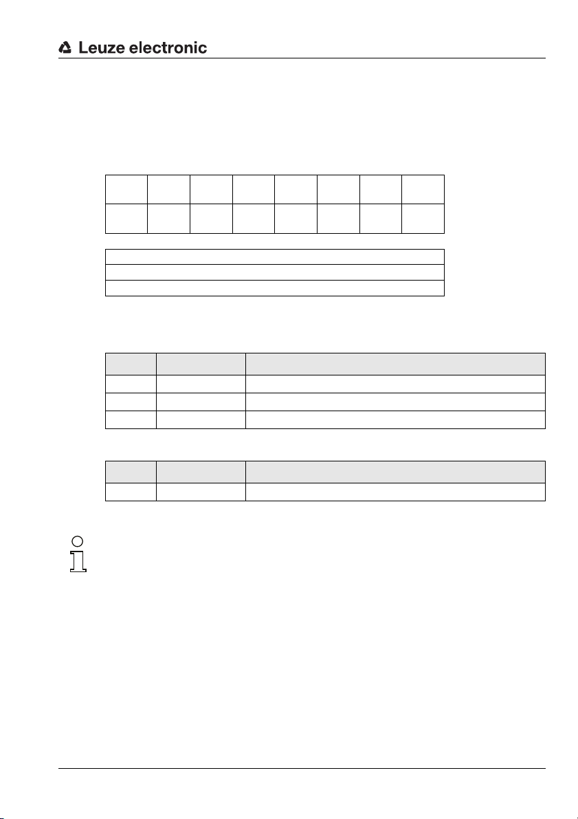
10.2 Description of the input bytes (status bytes)
10.2.1 Structure and meaning of the input bytes (status bytes)
7 6 5 4 3 2 1 0
ND Reserved DL Reserved Reserved SMA Reserved Status byte 0
DLC7 DLC6 DLC5 DLC4 DLC3 DLC2 DLC1 DLC0 Status byte 1
Telegram
Data byte / parameter byte 0
Data byte / parameter byte 1
…
Data
Table 10.1: Structure of the input bytes (status bytes)
Bits of the input byte (status byte) 0
Bit no. Designation Meaning
2 SMA Service mode active(service mode activated)
5 DL Data loss
7 ND New data only in Transparent mode
Bits of the input byte (status byte) 1
Bit no. Designation Meaning
0 … 7 DLC0 … DLC7 Data Length Code (length of the following user data)
Notice!
T-bit means toggle bit, i.e. this bit changes its state on each event ("0" "1" or "1" "0").
TNT 35/7-24V
Leuze electronic MA 208i 45
Page 48
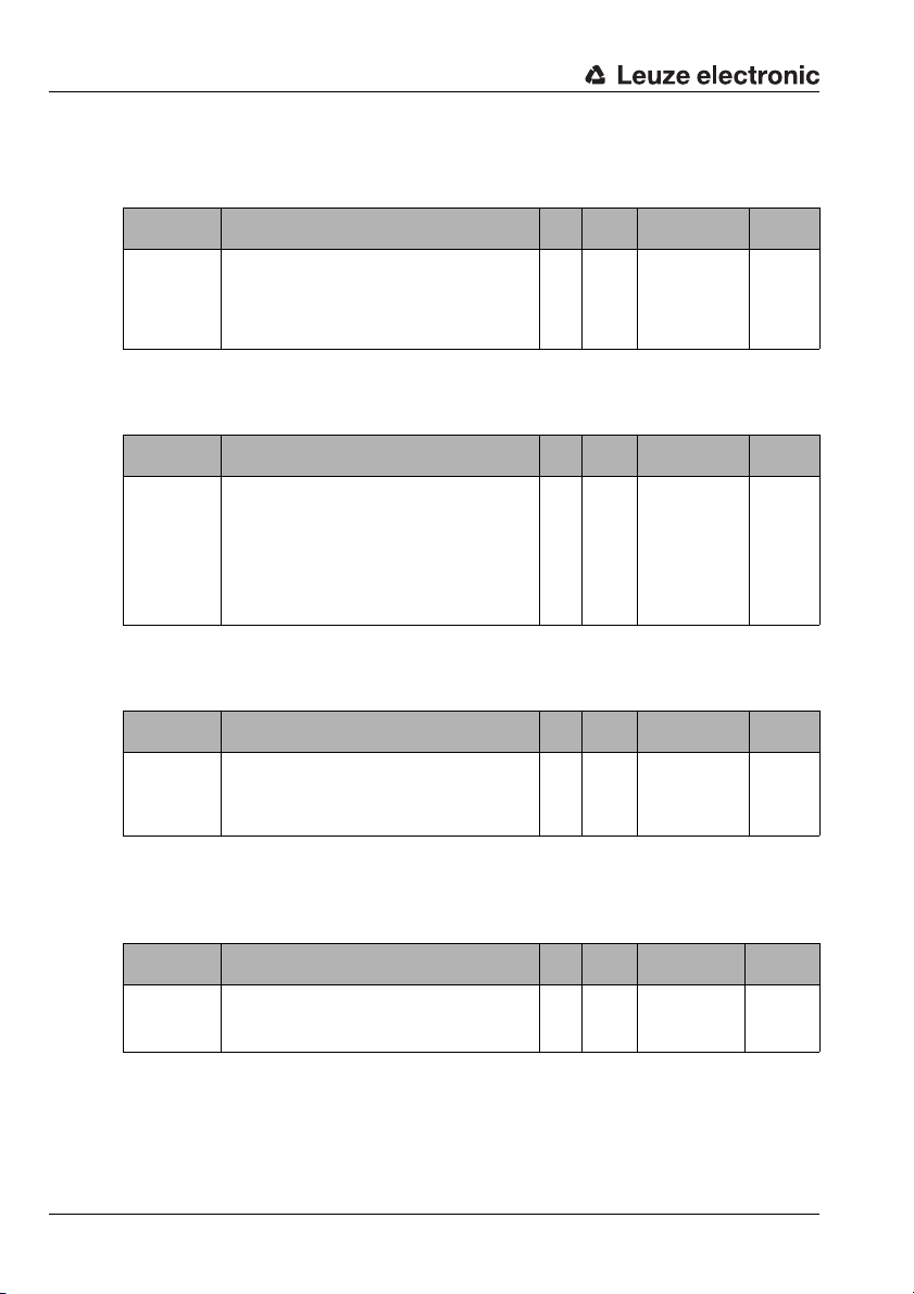
Telegram
10.2.2 Detailed description of the bits (input byte 0)
Bit 2: Service mode active: SMA
Input data Description Addr. Data
Service mode active (SMA)
The SMA bit is set if the service switch is set to "MA" or
SMA
"DEV", i.e. if the device is in either fieldbus gateway or Leuze
device service mode. This is also indicated by a flashing PWR
LED on the front side of the device. Upon changing to the
normal operating mode "RUN", the bit is reset.
0.2 Bit
Value range Default
type
0: Device in
operating mode
1: Device in service
mode
0h
Bit 5: Data loss: DL
This bit is important for monitoring data transmission in Transparent and Collective mode.
Input data Description Addr. Data
Data loss
(Data transmission monitoring)
This bit is set if gateway data could not be sent to the PLC
DL
and were lost. Furthermore, this bit is set in case the configured data frame, e.g. 8 bit, should be smaller than the data
to be transmitted to the PLC, e.g. bar code with 20 digits. In
this case, the first 8 digits are transmitted to the PLC, the rest
are truncated and are lost. In this process, the Data loss bit
is also set.
0.6 Bit
Value range Default
type
0->1:
Data loss
0
Bit 7: New data: ND
This bit is only relevant in Transparent mode.
Input data Description Addr. Data
New data
ND
(new data)
This bit is toggled on each data set that is sent from the gateway to the PLC. This can be used to differentiate between
multiple, identical data sets that are sent to the PLC.
0.7 Bit
Value range Default
type
0->1; 1->0:
On each status
change for new data
0
10.2.3 Detailed description of the bits (input byte 1)
Bit 0 … 7: Data length code: DLC0 … DLC7
Input data Description Addr. Data
Data length code
DLC0 … DLC7
(number of user data in bytes)
Stored in these bits is the number of user data bytes transmitted to the PLC which follow.
1.0 …
1.7
Value range Default
type
1h (00001b) …
Bit
FFh (00255b)
0h (00000b)
46 MA 208i Leuze electronic
Page 49

10.3 Description of the output bytes (control bytes)
10.3.1 Structure and meaning of the output bytes (control bytes)
7 6 5 4 3 2 1 0
ND Address 4 Address 3 Address 2 Address 1 Address 0 Broadcast
Reserved Reserved Reserved Reserved Control byte 1
Command
mode
Telegram
Control byte 0
Data byte 1
…
Table 10.2: Structure of the output bytes (control bytes)
Bits of the output byte (control byte) 0
Bit no. Designation Meaning
0 Command mode Command mode
1 Broadcast Broadcast
(only relevant with a connected MA 3x)
2 … 6 Address 0 .. 4 Address bits 0 .. 4
(only relevant with a connected MA 3x)
7 ND New data
DataData byte 2
TNT 35/7-24V
Leuze electronic MA 208i 47
Page 50

Telegram
10.3.2 Detailed description of the bits (output byte 0)
Bit 0: Command mode: Command mode
Output data Description Addr. Data
Command mode
This bit is used to activate Command mode. In Command
Command mode
mode, no data is sent by the PLC to the Leuze end device via
the gateway. In Command mode, various bits that execute
corresponding commands depending on the selected Leuze
device can be set in the data- or parameter field. For further
information, see chapter 11.1.2 "Command mode".
0.0 Bit
Value range Default
type
0: Default, transparent data transmission
1: Command mode
0
The following two control bits ("Bit 1: Broadcast: Broadcast" on page 48 and "Bits 2 … 6:
address bits 0 .. 4: address 0 .. 4" on page 48) are only relevant with a connected MA 3x.
With other devices, these fields are ignored.
Bit 1: Broadcast: Broadcast
Output data Description Addr. Data
Broadcast
Broadcast
A broadcast only functions with a multiNet network connected via the MA 3x. If this bit is activated, the gateway
automatically adds the broadcast command "00B" before
the data. This is directed at all participants in the multiNet.
0.1 Bit
Value range Default
type
0: No broadcast
1: Broadcast
0
Bits 2 … 6: address bits 0 .. 4: address 0 .. 4
Output data Description Addr. Data
Address bits 0 .. 4
Address 0..4
As with the broadcast command, individual devices in the
multiNet can also be addressed via the MA 3x . In this case,
the corresponding address of the device precedes the data
field telegram.
0.2
…
0.6
Value range Default
type
00000: Addr. 0
00001: Addr. 1
Bit
00010: Addr. 2
00011: Addr. 3
…
0
Bit 7: New data: ND
Output data Description Addr. Data
ND
New data
This bit is needed if several identical pieces of data are to be
sent in sequence.
0.7 Bit
Value range Default
type
0->1; 1->0:
On each status
change for new data
0
48 MA 208i Leuze electronic
Page 51

11 Modes
11.1 Functionality of the data exchange
Transparent mode (standard setting)
In Transparent mode, all data is sent 1:1 and directly by the serial end device to the PLC.
It is not necessary to use status and control bits here. However, only data bytes possible
for one transmission cycle are transmitted - all others are lost.
The distance between two successive telegrams (without frame) must be more than 20 ms,
since there is otherwise no clear separation between them.
ASCII characters are typically expected as data content; under certain circumstances, the
MA therefore detects different control characters as invalid characters in the data range and
truncates them. At 00
bytes are also filled with 00h .
11.1.1 Writing slave data in Collective mode (PLC -> gateway)
Examples for the activation of a Leuze device
In the data part (starting at byte 2) of the telegram to the gateway, a "+" (ASCII) is sent for
activation.
This means that the hex value "2B" (corresponds to a "+") is to be entered in control or output
byte 2. To deactivate the reading gate, a "2D" (hex) must be used instead (corresponds to
a "-" ASCII).
7 6 5 4 3 2 1 0
ND Address 4 Address 3 Address 2 Address 1 Address 0 Broadcast
in the data range, the MA cuts the telegram off because unnecessary
h
Command
mode
Modes
Control byte 0
Reserved Reserved Reserved Control byte 1
Data byte 1
…
7 6 5 4 3 2 1 0
0 0 0 0 0 0 0 0 Output byte 0
0 0 0 0 0 0 0 0 Output byte 1
0 0 0 0 0 0
0 0 0 0 0 0 0 0 Output byte 3
B 2 Output byte 2
DataData byte 2
Leuze electronic MA 208i 49
TNT 35/7-24V
Page 52

Modes
11.1.2 Command mode
One specific feature is the so-called Command mode, which is defined via the output control
byte 0 (bit 0) ... and enables the control of the connected device per bit.
If the command mode is activated (command mode = 1), no data is sent by the PLC to the
Leuze end device via the gateway. The data from the MA to the PLC is transmitted in the
selected operating mode (Transparent/Collective).
With the Command mode, it is possible to set various device-specific bits in the data- or
parameter field that execute the corresponding serial commands (e.g., v, +, -, etc.). If, for
example, the version of the Leuze end device is to be queried, the corresponding bit is to
be set so that a "v" is sent to the Leuze device with the <STX> v <CR> <LF> frame.
The Leuze end device also answers the gateway with data (e.g. bar code content, NoRead,
device version, etc.) in response to most commands. The answer is immediately passed on
to the PLC by the gateway.
Notice!
The parameters available for the individual Leuze devices are listed in chapter 16.
Command mode cannot be used with hand-held scanners.
Examples for the activation of a Leuze device
In Command mode, control or output byte 0.0 is to be set for activating the Command mode.
Only the corresponding bit (control or output byte 2.1) then needs to be set for activating
and deactivating the reading gate.
7 6 5 4 3 2 1 0
0 0 0 0 0 0 0
0 0 0 0 0 0 0 0 Output byte 1
0 0 0 0 0 0
0 0 0 0 0 0 0 0 Output byte 3
1 Output byte 0
1 0 Output byte 2
50 MA 208i Leuze electronic
Page 53

Command mode sequence diagram
Device executes the corresponding function (cf. chap. 16).
For function to be reestablished, the ND bit and the selected bit
in byte 2 must be toggled, byte 0.0 can stay.
No
No
Yes
Yes
Bit 0.0 =1?
Byte 2:
Bit set?
Connected device can only be
addressed via HW or PLC data
telegram
e.g. +
Bit 0.0 signals that the respective bit
is evaluated as a "control bit" in
byte 2, and according to the position of the device selection switch,
executes a corresponding function
on the device via the stored table.
No detectable function
Select bit, or incorrect byte
Set control byte 0, bit 0.0 to 1
Modes
Figure 11.1: Execution of command after activation of the Command mode
Notice!
Further information on fieldbus telegram structure can be found in chapter 10.1. A specification
of all usable commands can be found in chapter "Specifications for Leuze end devices" on
page 67.
Leuze electronic MA 208i 51
TNT 35/7-24V
Page 54

Commissioning and configuration
M 12 connector
(A-coded)
M 12 socket
(A-coded)
M 12 socket
(D-coded)
M 12 socket
(D-coded)
12 Commissioning and configuration
12.1 Measures to be performed prior to the initial commissioning
Before commissioning, familiarize yourself with the operation and configuration of the
MA 208
i.
Before connecting the supply voltage, recheck all connections and ensure that they
have been properly made.
The Leuze device must be connected to the internal RS 232 device interface.
Connecting the Leuze device
Open the housing of the MA 208
for BCL 32) through the middle threaded opening.
Connect the cable to the internal device interface (X30, X31 or X32, see chapter 7.5.1).
Use rotary switch S4 (see chapter 8.2.5) to select the connected device.
Now screw the PG cable gland into the threaded opening to provide strain relief and
ensure protection class IP 65.
Finally, close the housing of the MA 208
Attention!
Only then may the supply voltage be applied.
Upon startup of the MA 208i, the device selection switch is queried and the gateway
automatically sets itself to the Leuze device.
i and guide the corresponding device cable (e.g., KB 031
i.
PWR IN
SWIO_2
GND VIN
321
5
4
FE
SWIO_1
VOUT
PWR OUT
SWIO_2
123
5
4
SWIO_1
GND
FE
Figure 12.1: Connections of the MA 208
LEUZE Device
i seen from below, device on mounting plate
HOST / BUS IN
RD+
TD+
123
4
RD-
TD-
TD+
Check the applied voltage. It must be in the range between +18V … 30 V DC.
Connecting functional earth FE
Ensure that the functional earth (FE) is connected correctly.
Unimpaired operation is only guaranteed when the functional earth is connected properly.
All electrical disturbances (EMC couplings) are discharged via the functional earth connection.
On delivery, the SWIO 1/2 are connected in parallel on PWR IN/OUT. This connection can
be separated with a jumper.
52 MA 208i Leuze electronic
BUS OUT
RD+
123
4
RD-
TD-
Page 55

Commissioning and configuration
12.2 Starting the device and setting the communication parameters
First, you must start the device and set the communication parameters of the MA 208i. With
the communication parameters, you determine how data is exchanged between MA 208
and host system, monitor PCs etc.
The communication parameters are independent of the topology in which the MA 208i is
operated (see "Ethernet" on page 18).
On delivery, the MA 208
Notice!
The default address of the MA is 192.168.61.100.
The setting can be adapted via Leuze configuration software BCL-Config, BPS-Config or
RF-Config. In these tools, the MA 208
parameters in the usual way via the service interface.
12.2.1 Manually setting the IP address
If the IP address of the devices should be permanently set on your system, proceed as
follows:
Have the network administrator specify the data for IP address, net mask and gateway
address of the MA 208
Select the connected device via the device selection switch.
Apply the supply voltage +18 … 30 V DC (typ. +24 V DC); the MA 208
Now switch the service switch to "MA".
i is assigned a permanent IP address.
i has been created as a device to enable setting of
i.
i starts up.
i
Notice!
The service switch must be in switch position "MA" here so that the MA 208
addressed via the service interface.
Connect the serial RS 232 Sub-D interface of the MA 208
PC.
Make the necessary settings in the configuration window.
Leuze electronic MA 208i 53
i to the serial interface of your
i can be
TNT 35/7-24V
Page 56

Commissioning and configuration
Figure 12.2: Setting the parameters manually
12.2.2 Ethernet host communication
The Ethernet host communication enables the configuration of connections to an external
host system. Both UDP as well as TCP/IP (in either client or server mode) can be used. The
connection-free UDP protocol is used primarily to transfer process data to the host (monitor
operation). The connection-oriented TCP/IP protocol can also be used to transfer
commands from the host to the device. With this connection, the data is backed up by the
TCP/IP protocol itself.
If you would like to use the TCP/IP protocol, you must also define whether the MA 208
to operate as a TCP client or as a TCP server.
Contact your network administrator to determine which communication protocol is used.
54 MA 208i Leuze electronic
i is
Page 57

12.2.3 TCP/IP
Set the TCP/IP mode of the MA 208
In TCP client mode, the MA 208
system (PC / PLC as server). The MA 208
(host system) and the port number on which the server (host system) accepts a connection.
In this case, the MA 208
With a MA 208
• IP address of the TCP server (normally the PLC/host computer)
• Port number of the TCP server
• Optional: Timeout for the wait time for an answer from the server
• Optional: Repetition time for renewed communication attempt following a timeout
In TCP server mode, the primary host system (PC / PLC) actively establishes the connection and the connected MA 208
requires information from the user regarding the local port of the MA 208
which the connection requests of a client application (host system) are to be accepted. If
there is a connection request and a connection is established by the primary host system
(PC / PLC as client), the MA 208
sent and received.
With a MA 208
• Port number for the communication of the MA 208
The corresponding adjustment options can be found in the configuration tool.
12.2.4 UDP
The MA 208
cation partner. Correspondingly, the host system (PC / PLC) now also requires the set IP
address of the MA 208
socket is formed via which the data can be sent and received.
Set the following values:
• IP address of the communication partner
• Port number of the communication partner
The corresponding adjustment options can be found in the configuration tool.
Commissioning and configuration
i.
i actively establishes the connection to the primary host
i requires from the user the IP address of the server
i determines when and with whom a connection is established!
i as TCP client, set the following values:
i waits for the connection to be set up. The TCP/IP stack
i (port number) on
i (server mode) accepts the connection. Data can then be
i as TCP server, also set the following values:
i with the TCP client
i requires from the user the IP address and the port number of the communi-
i and the selected port number. By assigning these parameters, a
TNT 35/7-24V
12.3 Setting the read parameters on the Leuze device
Commissioning the Leuze device
To commission a read station, you must prepare the Leuze device on the MA 208
reading task. Communication with the Leuze device occurs via the service interface.
Leuze electronic MA 208i 55
i for its
Page 58

Commissioning and configuration
Notice!
For further information on connecting and using the service interface, see chapter 9 "Configuration".
To do this, connect the Leuze device to the MA 208i.
Depending on the Leuze device, this occurs either via a connection cable (accessory no.:
KB 031-1000) or directly on the MA 208
switches can be accessed with the housing cover open.
Select the "DEV" service switch position.
Connect the service interface; call up the terminal program
Connect your PC to the service connector via the RS 232 cable.
On the PC, call up a terminal program (e.g., BCL-Config) and check whether the interface
(COM 1 or COM 2) to which you have connected the MA 208
standard setting: 9600 baud, 8 data bits, no parity, 1 stop bit and STX, data, CR, LF.
You can download the config. tool from www.leuze.com -> Download -> Identify for BCL,
RFID, VR etc.
In order to communicate with the connected Leuze device, the STX, data, CR, LF framing
must be set on the PC terminal program, as the Leuze device is preconfigured ex works for
this frame character.
STX (02h): Prefix 1
CR (0Dh): Postfix 1
LF (0Ah): Postfix 2
i. The service connector and corresponding
i is set to the following Leuze
Operation
Switch the MA 208
The Leuze device is now connected to the fieldbus. Activation of the Leuze device can now
occur via the switching input on the MA 208
or by transmitting a "+" command to the Leuze device (see chapter 16 "Specifications for
Leuze end devices"). For further information on the fieldbus transmission protocol, see
chapter 10 "Telegram".
i to switch position "RUN" (operation).
i, via the process data word Out bit 1 (bit 0.2)
Reading out information in service mode
Set the service switch of the gateway to switch position "MA" (gateway).
Send a "v" command to call up all service information of the MA 208
An overview of the available commands and information can be found in chapter "Reading
out information in Service mode" on page 40.
56 MA 208i Leuze electronic
i.
Page 59

Commissioning and configuration
12.3.1 Specific feature for the use of hand-held scanners
(bar code and 2D devices, combi devices with RFID)
Notice!
For a description of device configuration and the required codes, please see the
corresponding documentation at www.leuze.com -> Download -> identify -> Bar code
hand-held readers or 2D code hand-held readers.
12.3.1.1 Cable-connected hand-held scanners on the MA 208
All hand-held scanners and mobile combi devices available in the Leuze electronic product
line can be used with the corresponding connection cable.
When using the MA 208
connected to the interface by means of a cable via the 9-pin Sub-D connector (voltage on
PIN 9). The corresponding cable is to be selected for the respective hand-held scanner and
ordered separately. The 9-pin Sub-D cable (KB JST-HS-300, Part No. 50113397) is
connected to this cable, which is connected to the MA 208
separately.
In this example, triggering occurs by means of a trigger button on the hand-held scanner.
12.3.1.2 Wireless hand-held scanners on the MA 208
All wireless hand-held scanners and mobile combi devices available in the Leuze electronic
product line can be used with the corresponding connection cable via the base station.
A 230 VAC connection (socket) is usually necessary for the charging station. Here, a data
connection of the charging station is established with the MA 208
is to be selected for the respective hand-held scanner and ordered separately. The 9-pin
Sub-D cable (KB JST-HS-300, part no. 50113397) is connected to this cable, which is
connected to the MA 208
In this example, triggering occurs by means of a trigger button on the hand-held scanner.
The following codes for configuring the devices are necessary for these devices as well.
i, the voltage supply of the hand-held scanner (5 V/at 1 A) can be
i. This cable must also be ordered
i
i. This cable must also be ordered separately.
i
i. The corresponding cable
TNT 35/7-24V
Leuze electronic MA 208i 57
Page 60

Commissioning and configuration
12.3.2 Specific features in the operation of an RFM/RFI
Shown here is a sample telegram for a write command in combination with an RFID device.
Notice!
Also note that all characters which are sent to a transponder are hex-encoded ASCII
characters. Each of these (hexadecimal) characters is, in turn, to be handled as an individual
ASCII character and converted to hexadecimal format for transmission via the fieldbus.
Example:
7 6 5 4 3 2 1 0
00 00 00 00 00 00 00 00 Control byte 0
00 00 00 00 00 00 00 00 Control byte 1
34 35 31 31 30 35 30 57
00 00 34 37 33 37 35 36
Data
HEX 5730353031313534363537333734
CHAR W0501154657374
Plain text T e s t
58 MA 208i Leuze electronic
Page 61

Diagnostics and troubleshooting
13 Diagnostics and troubleshooting
If problems should occur during commissioning of the MA 208i you can refer to the following
table. Typical errors and their possible causes are described here as well as tips for their
elimination.
13.1 General causes of errors
Error Possible error causes Measures
Data loss
(DL bit)
Data telegram longer than the bus
telegram in bus cycle/memory size.
Increase in bus telegram length.
Toggle out data earlier.
PWR status LED on the circuit board
Off
Green/orange,
flashing
Continuous orange
light
COM LED on the housing (see figure 8.1 on page 34)
Red continuous light Configuration error. Check interface.
PWR LED on the housing (see figure 8.1 on page 34)
Off No supply voltage connected to the device. Check supply voltage.
Green, flashing SERVICE active. Service switch on RUN.
Red, flashing Incorrect baud rate / address.
Red continuous light Device error. Send the device to customer service.
LINK /RX/TX LEDs on the housing (see figure 8.1 on page 34)
Off No connection. Check wiring/IP address.
Table 13.1: General causes of errors
No supply voltage connected to the device. Check supply voltage.
Hardware error. Send the device to customer service.
Device in boot mode.
Device error.
Firmware update failed.
No valid firmware, send device to
customer service.
Send the device to customer service.
Check switch settings.
Check baud rate or address.
TNT 35/7-24V
Leuze electronic MA 208i 59
Page 62

Diagnostics and troubleshooting
13.2 Interface errors
Error Possible error causes Measures
No communication via
Ethernet interface
COM continuous red
light LED
Sporadic errors at the
Ethernet interface
Figure 13.1: Interface error
Notice!
Please use chapter 13 as a master copy should servicing be required.
Cross the items in the "Measures" column which you have already examined, fill out the
following address field and fax the pages together with your service contract to the fax
number listed below.
Customer data (please complete)
Device type:
Company:
Contact partner / department:
Phone (direct):
Fax:
Street / No:
ZIP code/City:
Country:
Incorrect wiring. Check wiring.
Different protocol settings. Check protocol settings.
Protocol not released. Activate TCP/ IP or UDP.
Incorrect wiring.
Effects due to EMC.
Overall network expansion
exceeded.
Check wiring.
In particular, check wire shielding.
Check the cable used.
Check shielding (shield covering in place up to
the clamping point).
Check grounding concept and connection to
functional earth (FE).
Avoid EMC coupling caused by power cables laid
parallel to device lines.
Check max. network expansion as a function of
the max. cable lengths.
Leuze Service fax number:
+49 7021 573 - 199
60 MA 208i Leuze electronic
Page 63

14 Type overview and accessories
14.1 Part number code
MA
2xx i
i = Integrated fieldbus technology
08 Ethernet TCP/IP
35 CANopen
38 EtherCAT
48 PROFINET RT
55 DeviceNet
58 EtherNet/IP
MA Modular interfacing unit
14.2 Type overview
Type designation Description Description
MA 204
i PROFIBUS gateway 50112893
i Ethernet TCP/IP gateway 50112892
MA 208
MA 235
i CANopen gateway 50114154
MA 238
i EtherCAT gateway 50114155
i PROFINET-IO RT gateway 50112891
MA 248
MA 255
i DeviceNet gateway 50114156
MA 258
i EtherNet/IP gateway 50114157
Table 14.1: Type overview MA 2xxi
Interface 04 PROFIBUS DP
Type overview and accessories
14.3 Accessory connectors
Type designation Description Description
KD 095-5A M 12 socket for voltage supply 50020501
KS 095-4A M 12 connector for SW IN/OUT 50040155
D-ET1 RJ45 connector for user-configuration 50108991
KDS ET M12 / RJ 45 W - 4P Converter from M 12 D-coded to RJ 45 socket 50109832
Table 14.2: Connectors for the MA 208
Leuze electronic MA 208i 61
i
TNT 35/7-24V
Page 64

Type overview and accessories
PWR IN
1
2
3
4
SWIO_2
SWIO_1
FE
5
GNDVIN
M 12 socket
(A-coded)
M 12 connector
(A-coded)
14.4 Accessory ready-made cables for voltage supply
14.4.1 Contact assignment of PWR connection cable
PWR IN (5-pin socket, A-coded)
Pin Name Core color
1 VIN brown
2 SWIO_2 white
3 GND blue
4 SWIO_1 black
5 FE gray
Thread FE bare
PWR OUT (5-pin connector, A-coded)
Pin Name Core color
1VOUT brown
2SWIO_2 white
3GND blue
4SWIO_1 black
5FE gray
Thread FE bare
GND
FE
PWR OUT
SWIO_2
2
3
5
4
SWIO_1
1
VOUT
14.4.2 Specifications of the cables for voltage supply
Operating temperature range in rest state: -30° C … +70° C
in motion: 5° C … +70° C
Material sheathing: PVC
Bending radius > 50 mm
62 MA 208i Leuze electronic
Page 65

Type overview and accessories
Ethernet
TD+
RD+
TD
RD
SH
M12 connector
(D-coded)
Core color
Conductor class: VDE 0295, EN 60228, IEC 60228 (class 5)
WH
YE
BU
OG
14.4.3 Order codes of the cables for voltage supply
Type designation Description Part no.
K-D M12A-5P-5m-PVC
K-D M12A-5P-10m-PVC
Table 14.3: PWR cables for the MA 208i
M 12 socket for PWR, axial plug outlet,
open cable end, cable length 5 m
M 12 socket for PWR, axial plug outlet,
open cable end, cable length 10 m
50104557
50104559
14.5 Accessory ready-made cables for bus connection
14.5.1 General information
• Cable KB ET… for connecting to Industrial Ethernet via M 12 connector
• Standard cable available in lengths from 2 … 30 m
• Special cables on request
14.5.2 Contact assignments of M 12 Ethernet connection cable KB ET…
M 12 Ethernet connection cable (4-pin connector, D-coded, on both sides)
Pin Name Core color
1 TD+ yellow
2 RD+ white
3 TD- orange
4 RD- blue
SH (thread) FE bare
Figure 14.1: Cable structure of Industrial Ethernet connection cable
Leuze electronic MA 208i 63
TNT 35/7-24V
Page 66

Type overview and accessories
14.5.3 Technical data of M 12 Ethernet connection cable KB ET…
Operating temperature range in rest state: -50°C … +80°C
in motion: -25°C … +80°C
in motion: -25°C … +60°C (when used with drag chains)
Material cable sheath: PUR (green), wire insulation: PE foam,
free of halogens, silicone and PVC
Bending radius > 65 mm, suitable for drag chains
Bending cycles > 106, perm. acceleration < 5 m/s
14.5.4 Order codes of M 12 Ethernet connection cable KB ET…
Type designation Description Part no.
M 12 connector for BUS IN, axial connector, open cable end
KB ET - 1000 - SA Cable length 1 m 50106738
KB ET - 2000 - SA Cable length 2 m 50106739
KB ET - 5000 - SA Cable length 5 m 50106740
KB ET - 10000 - SA Cable length 10 m 50106741
M 12 connector for BUS IN to RJ-45 connector
KB ET - 1000 - SA-RJ45 Cable length 1 m 50109879
KB ET - 2000 - SA-RJ45 Cable length 2 m 50109880
KB ET - 5000 - SA-RJ45 Cable length 5 m 50109881
KB ET - 10000 - SA-RJ45 Cable length 10 m 50109882
M 12 connector + M 12 connector for BUS OUT to BUS IN
KB ET - 1000 - SSA Cable length 1 m 50106898
KB ET - 2000 - SSA Cable length 2 m 50106899
KB ET - 5000 - SSA Cable length 5 m 50106900
KB ET - 10000 - SSA Cable length 10 m 50106901
Table 14.4: Bus connection cable for the MA 208i
2
64 MA 208i Leuze electronic
Page 67

Type overview and accessories
14.6 Accessory ready-made cables for connecting Leuze Ident devices
14.6.1 Order codes for the device connection cables
Type designation Description Part no.
KB JST-3000 MA 31, BCL 90, IMRFU-1(RFU), cable length 3 m 50115044
KB JST-HS-300 Hand-held scanner, cable length 0.3 m 50113397
KB JST-M12A-5P-3000 BPS 8, BCL 8, cable length 3 m 50113467
KB JST-M12A-8P-Y-3000 LSIS 4x2i, cable length 3 m 50113468
KB JST-M12A-8P-3000 LSIS 122, cable length 3 m 50111225
K-D M12A-5P-5m-PVC Voltage supply, cable length 5 m 50104557
K-D M12A-5P-10m-PVC Voltage supply, cable length 10 m 50104559
K-DS M12A-MA-5P-3m-S-PUR ODS 96B with RS 232 50115049
K-DS M12A-MA-8P-3m-S-PUR ODSL 30/D 232-M12 50115050
K-DS M12A-MA-5P-3m-1S-PUR Konturflex Quattro RSX 50116791
KB AMS 1000 SA AMS 200, cable length 1 m 50106978
KB 500-3000-Y BCL 300i, BCL 500i,cable length 3 m 50110240
KB 031 1000 BCL 32, cable length 1 m 50103621
KB 031 3000 BCL 32, cable length 3 m 50035355
Table 14.5: Device connection cables for the MA 208
Notice!
The BCL 22 devices with JST connector, RFM xx and RFI xx can be connected directly with
the injection molded device cable.
14.6.2 Contact assignment for the device connection cables
i
K-D M12A-5P-5000/10000 connection cable (5-pin with injection molded connector), open cable end
Pin Core color
1brown
2white
3blue
4black
5gray
KB JST 3000 (RS 232 connection cable, JST pin strip 10-pin, open cable end)
Signal Core color JST 10-pin
TxD 232 red 5
RxD 232 brown 4
GND orange 9
FE shield 10
Leuze electronic MA 208i 65
TNT 35/7-24V
Page 68

Maintenance
15 Maintenance
15.1 General maintenance information
The MA 208
15.2 Repairs, servicing
Repairs to the device must only be carried out by the manufacturer.
Contact your Leuze distributor or service organization should repairs be required.
The addresses can be found on the inside of the cover and on the back.
Notice!
When sending devices to Leuze electronic for repair, please provide an accurate description
of the error.
15.3 Disassembling, packing, disposing
Repacking
For later reuse, the device is to be packed so that it is protected.
Notice!
Electrical scrap is a special waste product! Observe the locally applicable regulations
regarding disposal of the product.
i does not require any maintenance by the operator.
66 MA 208i Leuze electronic
Page 69

Specifications for Leuze end devices
16 Specifications for Leuze end devices
Serial interface and Command mode
The corresponding Leuze end device can be selected while configuring the fieldbus gateway
(see chapter 9 "Configuration").
The exact specifications for the individual Leuze end devices can be found in the following
sections and in the device description.
The corresponding serial command is sent to the Leuze end device in Command mode. To
send the corresponding command to the RS 232 device after activating the Command
mode in byte 0 (control bit 0.0), set the corresponding bit in byte 2.
The Leuze end device also responds to most commands by sending data, such as the bar
code contents, NoRead, device version, etc., back to the gateway. The answer is not evaluated by the gateway, but is instead passed on to the PLC.
For the BPS 8, AMS and hand-held scanners, a number of specific features are to be noted.
16.1 Standard setting, KONTURflex (S4 switch position 0)
This switch position can be used with almost all devices, since a data frame is transmitted
along with it if necessary. A 00h in the data range of the control is interpreted as the end of
a telegram/invalid, however.
The distance between two successive telegrams (without frame) must be more than 20 ms
in this switch position, since there is otherwise no clear separation between them. If necessary, the settings have to be adjusted on the device.
Leuze measuring sensors with RS 232 interface (such as a KONTURflex Quattro RS) do not
necessarily use a telegram frame, which is why these are also operated in switch position 0.
Specifications for the serial interface
Default parameter Standard
Baud rate 9600
Data mode 8N1
Handshake no
Protocol framing protocol without acknowledgment
Frame <Data>
Data mode transparent
Notice!
The data frame is specified via the switch position.
In the factory setting, the S4 switch position is 0. Resetting the settings to these is possible
in S4 switch position F. The procedure for doing this is described in chapter 16.14.
Leuze electronic MA 208i 67
TNT 35/7-24V
Page 70

Specifications for Leuze end devices
KONTURflex specifications
Settings on the MA 208
• Ethernet address is freely selectable
• Device selection switch at position "0"
Ethernet settings
• Setting the data length is not required.
• User parameters:
"Transparent mode", baud rate 38400, "4 data bits", "no parity", "2 stop bits"
KONTURflex settings
First, the following settings are to be performed on the device using KONTURFlex-Soft:
• Either "Autosend (fast)" or "Autosend with data in Modbus format"
• Repeat time "31.5 ms"
• Autosend baud rate "38.4 KB"
• 2 stop bits, no parity
i
68 MA 208i Leuze electronic
Page 71

Specifications for Leuze end devices
16.2 Bar code reader BCL 8 (S4 switch position 1)
Specifications for the serial interface
Default parameter BCL 8
Baud rate 9600
Data mode 8N1
Handshake no
Protocol framing protocol without acknowledgment
Frame <STX> <Data> <CR> <LF>
Specifications for Command mode
To activate the Command mode, bit 0 must be set to 1 in control byte 0.
For further information, see chapter 11.1.2 "Command mode", figure 11.1.
Control bit Meaning Corresponds to
0 Version query v
1 Activation / deactivation reading gate + / 2 Reference-code 1 teach-in RT1
3 Reference-code 2 teach-in RT2
4 Automatic configuration of reading task activation / deactivation CA+ / CA5 Switching output 1 activation OA1
6
7 Switching output 1 deactivation OD1
8 System standby SOS
9 System active SON
10 Query reflector polling AR?
11 Output version of the boot kernel with check sum VB
12 Output version of the decoder program with check sum VK
13 Reset parameters to default values PC20
14 Device restart H
Recommended settings
Setting the data length is not required.
serial command
(ASCII)
TNT 35/7-24V
Leuze electronic MA 208i 69
Page 72

Specifications for Leuze end devices
16.3 Bar code reader BCL 22 (S4 switch position 2)
Specifications for the serial interface
Default parameter BCL 22
Baud rate 9600
Data mode 8N1
Handshake no
Protocol framing protocol without acknowledgment
Frame <STX> <Data> <CR> <LF>
Specifications for Command mode
To activate the Command mode, bit 0 must be set to 1 in control byte 0.
For further information, see chapter 11.1.2 "Command mode", figure 11.1.
Control bit Meaning Corresponds to
0 Version query v
1 Activation / deactivation reading gate + / 2 Reference-code 1 teach-in RT1
3 Reference-code 2 teach-in RT2
4 Automatic configuration of reading task activation / deactivation CA+ / CA5 Switching output 1 activation OA1
6 Switching output 2 activation OA2
7 Switching output 1 deactivation OD1
8 Switching output 2 deactivation OD2
9
10
11 Output version of the boot kernel with check sum VB
12 Output version of the decoder program with check sum VK
13 Reset parameters to default values PC20
14 Device restart H
15
serial command
(ASCII)
Recommended settings
Setting the data length is not required.
70 MA 208i Leuze electronic
Page 73

Specifications for Leuze end devices
16.4 Bar code reader BCL 32 (S4 switch position 3)
Specifications for the serial interface
Default parameter BCL 32
Baud rate 9600
Data mode 8N1
Handshake no
Protocol framing protocol without acknowledgment
Frame <STX> <Data> <CR> <LF>
Specifications for Command mode
To activate the Command mode, bit 0 must be set to 1 in control byte 0.
For further information, see chapter 11.1.2 "Command mode", figure 11.1.
Control bit Meaning Corresponds to
0 Version query v
1 Activation / deactivation reading gate + / 2 Reference code teach-in activation / deactivation , / .
3
4 Automatic configuration of reading task activation / deactivation CA+ / CA5 Switching output 1 activation OA1
6 Switching output 2 activation OA2
7 Switching output 1 deactivation OD1
8 Switching output 2 deactivation OD2
9
10
11
12
13
14 Reset parameters to default values PC20
15 Device restart H
serial command
(ASCII)
TNT 35/7-24V
Recommended settings
Setting the data length is not required.
Leuze electronic MA 208i 71
Page 74

Specifications for Leuze end devices
16.5 Bar code reader BCL 300i, BCL 500i (S4 switch position 4)
Specifications for the serial interface
Default parameter BCL 300i, BCL 500i
Baud rate 9600
Data mode 8N1
Handshake no
Protocol framing protocol without acknowledgment
Frame <STX> <Data> <CR> <LF>
Specifications for Command mode
To activate the Command mode, bit 0 must be set to 1 in control byte 0.
For further information, see chapter 11.1.2 "Command mode", figure 11.1.
Control bit Meaning Corresponds to
0 Version query v
1 Activation / deactivation reading gate + / 2 Reference code teach-in activation / deactivation RT+ / RT3
4 Autom. configuration of reading task activation / deact. CA+ / CA5 Switching output 1 activation OA1
6 Switching output 2 activation OA2
7 Switching output 1 deactivation OD1
8 Switching output 2 deactivation OD2
9
10
11
12
13 Parameter - difference to default parameter set PD20
14 Reset parameters to default values PC20
15 Device restart H
serial command
(ASCII)
Recommended settings
Setting the data length is not required.
72 MA 208i Leuze electronic
Page 75

Specifications for Leuze end devices
16.6 Bar code reader BCL 90 (S4 switch position 5)
Specifications for the serial interface
Default parameter BCL 90
Baud rate 9600
Data mode 8N1
Handshake no
Protocol framing protocol without acknowledgment
Frame <STX> <Data> <CR> <LF>
Specifications for Command mode
To activate the Command mode, bit 0 must be set to 1 in control byte 0.
For further information, see chapter 11.1.2 "Command mode", figure 11.1.
Control bit Meaning Corresponds to
0 Version query v
1 Activation / deactivation reading gate + / 2 Configuration mode 11
3 Alignment mode 12
4 Read operation 13
5
6
7
8
9
10
11
12
13
14 Reset parameters to default values PC20
15 Device restart H
serial command
(ASCII)
TNT 35/7-24V
Recommended settings
Setting the data length is not required.
Leuze electronic MA 208i 73
Page 76

Specifications for Leuze end devices
16.7 LSIS 122 (S4 switch position 6)
Specifications for the serial interface
Default parameter LSIS 122
Baud rate 9600
Data mode 8N1
Handshake no
Protocol framing protocol without acknowledgment
Frame <STX> <Data> <CR> <LF>
Specifications for Command mode
To activate the Command mode, bit 0 must be set to 1 in control byte 0.
For further information, see chapter 11.1.2 "Command mode", figure 11.1.
Control bit Meaning Corresponds to
0 Version query i
1 Activation/Deactivation of reading gate: 12h/14h <DC2> / <DC4>
2
3
4
5
6
7
8
9
10
11
12
13
14
15
serial command
(ASCII)
Recommended settings
Setting the data length is not required.
74 MA 208i Leuze electronic
Page 77

16.8 LSIS 4x2i (S4 switch position 7)
Specifications for the serial interface
Default parameter LSIS 4x2i
Baud rate 9600
Data mode 8N1
Handshake no
Protocol framing protocol without acknowledgment
Frame <STX> <Data> <CR> <LF>
Specifications for Command mode
To activate the Command mode, bit 0 must be set to 1 in control byte 0.
For further information, see chapter 11.1.2 "Command mode", figure 11.1.
Control bit Meaning Corresponds to
0 Version query v
1 Image acquisition trigger +
2
3
4
5
6
7
8
9
10
11
12
13
14
15
Specifications for Leuze end devices
serial command
(ASCII)
TNT 35/7-24V
Recommended settings
Setting the data length is not required.
Leuze electronic MA 208i 75
Page 78

Specifications for Leuze end devices
16.9 Hand-held scanner (S4 switch position 8)
Specifications for the serial interface
Default parameter Hand-held scanner
Baud rate 9600
Data mode 8N1
Handshake no
Protocol framing protocol without acknowledgment
Frame <Data> <CR> <LF>
Notice!
Command mode cannot be used with hand-held scanners.
Recommended settings
Setting the data length is not required.
76 MA 208i Leuze electronic
Page 79

Specifications for Leuze end devices
16.10 RFI, RFM, RFU RFID readers (S4 switch position 9)
Specifications for the serial interface
Default parameter RFM 12,RFM 32 and RFM 62
RFI 32
RFU (via IMRFU)
Baud rate 9600
Data mode 8N1
Handshake no
Protocol framing protocol without acknowledgment
Frame <STX> <Data> <CR> <LF>
Specifications for Command mode
To activate the Command mode, bit 0 must be set to 1 in control byte 0.
For further information, see chapter 11.1.2 "Command mode", figure 11.1.
Control bit Meaning Corresponds to
0 Version query v
1 Activation / deactivation reading gate + / 2
3
4
5
6
7
8
9
10
11
12
13
14 Reset parameters to default values R
15 Device restart H
1) Not for IMRFU/RFU
serial command
(ASCII)
1)
1)
TNT 35/7-24V
Recommended settings
Setting the data length is not required.
The RFID devices expect the telegrams / data in HEX format.
Leuze electronic MA 208i 77
Page 80

Specifications for Leuze end devices
16.11 BPS 8 bar code positioning system (S4 switch position A)
Specifications for the serial interface
Default parameter BPS 8
Baud rate 57600
Data mode 8N1
Handshake no
Protocol binary protocol without acknowledgment
Frame <Data>
Specifications for Command mode
To activate the Command mode, bit 0 must be set to 1 in control byte 0.
For further information, see chapter 11.1.2 "Command mode", figure 11.1.
Control bit Meaning Corresponds to serial
command (HEX)
byte 1 byte 2
0 Request diagnostic info 01 01
1 Request marker info 02 02
2 Request SLEEP mode 04 04
3 Request position info 08 08
4 Request individual measurement 10 10
5
6
7
8
9
10
11
12
13
14
15
Recommended settings
Setting the data length is not required.
In this switch position, the MA automatically sends a position request to the BPS 8 every
10 ms until another command comes via the control. Automatic request only restarts when
a new position request is sent by the PLC or when the MA is restarted.
78 MA 208i Leuze electronic
Page 81

Specifications for Leuze end devices
16.12 AMS distance measurement device, ODSL xx optical distance sensors
with RS 232 interface (S4 switch position B)
Notice!
In this switch position, 6-byte data (fixed) is always expected by the device. This is why a
quick telegram sequence can be transmitted reliably even without a data frame.
AMS
Specifications for the serial interface
Default parameter AMS
Baud rate 38400
Data mode 8N1
Handshake no
Protocol binary protocol without acknowledgment
Frame <Data>
Specifications for Command mode
To activate the Command mode, bit 0 must be set to 1 in control byte 0.
For further information, see chapter 11.1.2 "Command mode", figure 11.1.
Control bit Meaning Corresponds to
serial command
(HEX)
0 Transmit individual position value = single shot C0F131
1 Cyclically transmit position values C0F232
2 Stop cyclical transmission C0F333
3 Laser diode on C0F434
4 Laser diode off C0F535
5 Transmit single speed value C0F636
6 Cyclically transmit speed values C0F737
7
8
9
10
11
12
13
14
15
Recommended settings
Setting the data length is not required.
Leuze electronic MA 208i 79
TNT 35/7-24V
Page 82

Specifications for Leuze end devices
ODSL 9, ODSL 30 and ODSL 96B
Notice!
The default settings of the ODS serial interface have to be adjusted! Further information on
configuration of the interface can be found in the technical description of the corresponding
device.
Specifications for the serial interface
Default parameter AMS
Baud rate 38400
Data mode 8N1
Handshake no
Protocol ASCII transmission, 5-digit measurement value
Frame <Data>
Specifications for Command mode
Command mode cannot be used with the ODSL 9, ODSL 30 and ODSL 96B.
The ODSL 9/96B is to be operated in the "Precision" measure mode. The mode is set
through the display menu via Application -> Measure mode -> Precision. You can find
more details on this in the technical description.
80MA 208i Leuze electronic
Page 83

Specifications for Leuze end devices
16.13 Modular interfacing unit MA 3x (S4 switch position C)
Specifications for the serial interface
Default parameter MA 3x
Baud rate 9600
Data mode 8N1
Handshake no
Protocol framing protocol without acknowledgment
Frame <STX> <Data> <CR> <LF>
Specifications for Command mode
To activate the Command mode, bit 0 must be set to 1 in control byte 0.
For further information, see chapter 11.1.2 "Command mode", figure 11.1.
Control bit Meaning Corresponds to
0 Version query v
1
2
3
4
5
6
7
8
9
10
11
12
13
14 Reset parameters to default values PC20
15 Device restart H
serial command
(ASCII)
TNT 35/7-24V
Recommended settings
Setting the data length is not required.
Notice!
In this switch position, the address of the multiNet slave is also transmitted in the first two
bytes of the data range!
Leuze electronic MA 208i 81
Page 84

Specifications for Leuze end devices
16.14 Resetting the parameters (S4 switch position F)
To reset all parameters of the MA that can be configured with software (such as baud rate,
IP address, dependent on type) to the factory settings, do the following:
Set device switch S4 to F in a voltage free state.
Switch the voltage on and wait until it is ready for operation.
If necessary, switch the voltage off to prepare for commissioning.
Set service switch S10 to the "RUN" position.
82MA 208i Leuze electronic
Page 85

17 Appendix
17.1 ASCII Table
HEX DEC CTRL ABB DESIGNATION MEANING
00 0 ^@ NUL NULL Zero
01 1 ^A SOH START OF HEADING Start of heading
02 2 ^B STX START OF TEXT Start of text characters
03 3 ^C ETX END OF TEXT Last character of text
04 4 ^D EOT END OF TRANSMISSION End of transmission
05 5 ^E ENQ ENQUIRY Request to transmit data
06 6 ^F ACK ACKNOWLEDGE Positive acknowledgment
07 7 ^G BEL BELL Bell signal
08 8 ^H BS BACKSPACE Backspace
09 9 ^I HT HORIZONTAL TABULATOR Horizontal tabulator
0A 10 ^J LF LINE FEED Line feed
0B 11 ^K VT VERTICAL TABULATOR Vertical tabulator
0C 12 ^L FF FORM FEED Form feed
0D 13 ^M CR CARRIAGE RETURN Carriage return
0E 14 ^N SO SHIFT OUT Shift out
0F 15 ^O SI SHIFT IN Shift in
10 16 ^P DLE DATA LINK ESCAPE Data link escape
11 17 ^Q DC1 DEVICE CONTROL 1 (X-ON) Device control character 1
12 18 ^R DC2 DEVICE CONTROL 2 (TAPE) Device control character 2
13 19 ^S DC3 DEVICE CONTROL 3 (X-OFF) Device control character 3
14 20 ^T DC4 DEVICE CONTROL 4 Device control character 4
15 21 ^U NAK NEGATIVE (/Tape) ACKNOWLEDGE Negative acknowledge
16 22 ^V SYN SYNCHRONOUS IDLE Synchronization
17 23 ^W ETB END OF TRANSMISSION BLOCK End of data transmission block
18 24 ^X CAN CANCEL Invalid
19 25 ^Y EM END OF MEDIUM End of medium
1A 26 ^Z SUB SUBSTITUTE Substitution
1B 27 ^[ ESC ESCAPE Escape
1C 28 ^\ FS FILE SEPARATOR File separator
1D 29 ^] GS GROUP SEPARATOR Group separator
1E 30 ^^ RS RECORD SEPARATOR Record separator
1F 31 ^_ US UNIT SEPARATOR Unit separator
20 32 SP SPACE Space
21 33 ! EXCLAMATION POINT Exclamation point
22 34 " QUOTATION MARK Quotation mark
23 35 # NUMBER SIGN Number sign
24 36 $ DOLLAR SIGN Dollar sign
25 37 % PERCENT SIGN Percent sign
26 38 & AMPERSAND Ampersand
27 39 ' APOSTROPHE Apostrophe
28 40 ( OPENING PARENTHESIS Opening parenthesis
Appendix
TNT 35/7-24V
Leuze electronic MA 208i 83
Page 86

Appendix
HEX DEC CTRL ABB DESIGNATION MEANING
29 41 ) CLOSING PARENTHESIS Closing parenthesis
2A 42 * ASTERISK Asterisk
2B 43 + PLUS Plus sign
2C 44 , COMMA Comma
2D 45 - HYPHEN (MINUS) Hyphen (minus)
2E 46 . PERIOD (DECIMAL) Period (decimal)
2F 47 / SLANT Slant
30 48 0
31 49 1
32 50 2
33 51 3
34 52 4
35 53 5
36 54 6
37 55 7
38 56 8
39 57 9
3A 58 : COLON Colon
3B 59 ; SEMICOLON Semicolon
3C 60 < LESS THAN Less than
3D 61 = EQUALS Equals
3E 62 > GREATER THAN Greater than
3F 63 ? QUESTION MARK Question mark
40 64 @ COMMERCIAL AT Commercial AT
41 65 A
42 66 B
43 67 C
44 68 D
45 69 E
46 70 F
47 71 G
48 72 H
49 73 I
4A 74 J
4B 75 K
4C 76 L
4D 77 M
4E 78 N
4F 79 O
50 80 P
51 81 Q
52 82 R
53 83 S
54 84 T
55 85 U
56 86 V
57 87 W
58 88 X
84MA 208i Leuze electronic
Page 87

HEX DEC CTRL ABB DESIGNATION MEANING
59 89 Y
5A 90 Z
5B 91 [ OPENING BRACKET Opening bracket
5C 92 \ REVERSE SLANT Reverse slant
5D 93 ] CLOSING BRACKET Closing bracket
5E 94 ^ CIRCUMFLEX Circumflex
5F 95 _ UNDERSCORE Underscore
60 96 ‘ GRAVE ACCENT Grave accent
61 97 a
62 98 b
63 99 c
64 100 d
65 101 e
66 102 f
67 103 g
68 104 h
69 105 i
6A 106 j
6B 107 k
6C 108 l
6D 109 m
6E 110 n
6F 111 o
70 112 p
71 113 q
72 114 r
73 115 s
74 116 t
75 117 u
76 118 v
77 119 w
78 120 x
79 121 y
7A 122 z
7B 123 { OPENING BRACE Opening brace
7C 124 | VERTICAL LINE Vertical line
7D 125 } CLOSING BRACE Closing brace
7E 126 ~ TILDE Tilde
7F 127 DEL DELETE (R UBOUT) Delete
Appendix
TNT 35/7-24V
Leuze electronic MA 208i 85
Page 88

Index
A
Accessories . . . . . . . . . . . . . . . . . . . . . . . . . 61
Bus connection cables . . . . . . . . . . . . . . 63
Cables for Leuze ident devices . . . . . . . 65
Connector . . . . . . . . . . . . . . . . . . . . . . . . 61
Voltage supply cables . . . . . . . . . . . . . . 62
Areas of application for the fieldbus gateway 8
ASCII Table . . . . . . . . . . . . . . . . . . . . . . . . . 83
C
Causes of errors
General . . . . . . . . . . . . . . . . . . . . . . . . . . 59
Interface . . . . . . . . . . . . . . . . . . . . . . . . . 60
Collective mode . . . . . . . . . . . . . . . . . . . . . . 15
Command mode . . . . . . . . . . . . . . . . . . 15, 50
Commissioning . . . . . . . . . . . . . . . . . . . . . . 52
Configuration . . . . . . . . . . . . . . . . . . . . . 40, 52
Connecting the Leuze device . . . . . . . . . . . 11
PCB connectors X30 … X32 . . . . . . . . . 38
Connections
PWR IN . . . . . . . . . . . . . . . . . . . . . . . . . . 27
PWR OUT switching input/output . . . . . 29
Control bytes . . . . . . . . . . . . . . . . . . . . . . . . 47
D
Declaration of Conformity . . . . . . . . . . . . . . . 5
Definition of terms . . . . . . . . . . . . . . . . . . . . . 7
Description of functions . . . . . . . . . . . . . . . . . 6
Device description . . . . . . . . . . . . . . . . . . . . 15
Device interface RS 232 . . . . . . . . . . . . . . . 31
Diagnosis . . . . . . . . . . . . . . . . . . . . . . . . . . . 59
Dimensioned drawings . . . . . . . . . . . . . . . . 21
Disassembling . . . . . . . . . . . . . . . . . . . . . . . 66
Disposing . . . . . . . . . . . . . . . . . . . . . . . . . . . 66
E
Electrical connection . . . . . . . . . . . . . . . . . . 10
Connecting the Leuze device . . . . . . . . . 11
Power supply and bus cable . . . . . . . . . 11
Safety notices . . . . . . . . . . . . . . . . . . . . . 26
Ethernet
Cable lengths and shielding . . . . . . . . . . 33
Wiring . . . . . . . . . . . . . . . . . . . . . . . . . . . 33
Ethernet connection cable . . . . . . . . . . . . . . 63
F
Fast commissioning . . . . . . . . . . . . . . . . . . . 10
Fieldbus systems . . . . . . . . . . . . . . . . . . . . . 18
I
Input byte 0
Data loss . . . . . . . . . . . . . . . . . . . . . . . . .46
New data . . . . . . . . . . . . . . . . . . . . . . . . . 46
Service mode active . . . . . . . . . . . . . . . .46
Input byte 1
Data length code . . . . . . . . . . . . . . . . . . .46
Intended use . . . . . . . . . . . . . . . . . . . . . . . . . . 8
Interface
Ethernet TCP/IP . . . . . . . . . . . . . . . . . . . . 31
L
LED status indicators . . . . . . . . . . . . . . . . . . 34
Leuze device
2D code reader
LSIS 122
LSIS 4x2i . . . . . . . . . . . . . . . . . . . . . . 75
Bar code positioning system (BPS)
BPS 8 . . . . . . . . . . . . . . . . . . . . . . . . . 78
Bar code reader (BCL)
BCL 22 . . . . . . . . . . . . . . . . . . . . . . . . 70
BCL 300i . . . . . . . . . . . . . . . . . . . . . . . 72
BCL 32 . . . . . . . . . . . . . . . . . . . . . . . . 71
BCL 500i . . . . . . . . . . . . . . . . . . . . . . . 72
BCL 8 . . . . . . . . . . . . . . . . . . . . . . . . . 69
BCL 90 . . . . . . . . . . . . . . . . . . . . . . . . 73
Distance measurement device
AMS . . . . . . . . . . . . . . . . . . . . . . . . . . 79
Hand-held scanner . . . . . . . . . . . . . . . . . 76
RFID read-write devices (RFM/RFI …)
RFM 12, 32 and 62 . . . . . . . . . . . . . . . 77
Setting the read parameters . . . . . . . . . . 55
Specific feature for hand-held scanners 57
Specifications for Command mode . . . . . 67
Specifications for the serial interface . . . 67
. . . . . . . . . . . . . . . . . . . . . . . 74
M
Maintenance . . . . . . . . . . . . . . . . . . . . . . . . . 66
Mounting
Device arrangement, selecting a mounting
location
. . . . . . . . . . . . . . . . . . . . . . 10, 25
Mounting the device . . . . . . . . . . . . 10, 24
86 MA 208i Leuze electronic
Page 89

Index
O
Operating modes
Operation . . . . . . . . . . . . . . . . . . . . . . . . . 17
Service fieldbus gateway . . . . . . . . . . . . . 17
Service Leuze device . . . . . . . . . . . . . . . . 17
Output byte 0
Address bits 0 .. 4 . . . . . . . . . . . . . . . . . . 48
Broadcast . . . . . . . . . . . . . . . . . . . . . . . . 48
Command mode . . . . . . . . . . . . . . . . . . . 48
New data . . . . . . . . . . . . . . . . . . . . . . . . . 48
P
Packing . . . . . . . . . . . . . . . . . . . . . . . . . . . . . 66
Q
Quality assurance . . . . . . . . . . . . . . . . . . . . . . 5
R
Repair . . . . . . . . . . . . . . . . . . . . . . . . . . . 8, 66
S
Safety notices . . . . . . . . . . . . . . . . . . . . . . . . . 8
Service interface . . . . . . . . . . . . . . . . . . 32, 38
Service mode
Commands . . . . . . . . . . . . . . . . . . . . . . . 41
Information . . . . . . . . . . . . . . . . . . . . . . . . 42
Service switch . . . . . . . . . . . . . . . . . . . . . . . . 38
Servicing . . . . . . . . . . . . . . . . . . . . . . . . . . . . 66
Specifications . . . . . . . . . . . . . . . . . . . . . . . . 20
Electrical data . . . . . . . . . . . . . . . . . . . . . 20
Environmental data . . . . . . . . . . . . . . . . . 21
Indicators . . . . . . . . . . . . . . . . . . . . . . . . . 20
Mechanical data . . . . . . . . . . . . . . . . . . . 20
Starting the device . . . . . . . . . . . . . . . . 11, 53
Status bytes . . . . . . . . . . . . . . . . . . . . . . . . . 45
Structure of the fieldbus telegram . . . . . . . . 44
Symbols . . . . . . . . . . . . . . . . . . . . . . . . . . . . . 5
W
Writing slave data . . . . . . . . . . . . . . . . . . . . 49
T
Telegram structure
Input bytes . . . . . . . . . . . . . . . . . . . . . . . . 45
Output bytes . . . . . . . . . . . . . . . . . . . . . . 47
Transparent mode . . . . . . . . . . . . . . . . . . . . 15
Troubleshooting . . . . . . . . . . . . . . . . . . . . . . 59
Type overview . . . . . . . . . . . . . . . . . . . . 22, 61
Leuze electronic MA 208i 87
 Loading...