

Page 1
LSIS 222 / LSIS 223
Code reader
en 01-2012/07 50119062
TECHNICAL DESCRIPTION
Page 2

Condelectric S.A
.
Tel. Int. + 54 1148 361053
Fax Int. + 54 1148 361053
Tel. Int. + 43 732 7646-0
Fax Int. + 43 732 7646-785
Balluff-Leuze Pty. Ltd.
Tel. Int. + 61 3 9720 4100
Fax Int. + 61 3 9738 2677
Leuze electronic nv/ sa
Tel. Int. + 32 2253 16-00
Fax Int. + 32 2253 15-36
ATICS
Tel. Int. + 359 2 847 6244
Fax Int. + 359 2 847 6244
Leuze electronic Ltda.
Tel. Int. + 55 11 5180-6130
Fax Int. + 55 11 5180-6141
Leuze electronic AG
Tel. Int. + 41 41 784 5656
Fax Int. + 41 41 784 5657
Imp. Tec. Vignola S.A.I.C.
Tel. Int. + 56 3235 11-11
Fax Int. + 56 3235 11-28
Leuze electronic Trading
(Shenzhen) Co. Ltd.
Tel. Int. + 86 755 862 64909
Fax Int. + 86 755 862 64901
Componentes Electronicas Ltda.
Tel. Int. + 57 4 3511049
Fax Int. + 57 4 3511019
Schmachtl CZ s.r.o.
Tel. Int. + 420 244 0015-00
Fax Int. + 420 244 9107-00
Leuze electronic Scandinavia ApS
Tel. Int. + 45 48 173200
SKS-automaatio Oy
Tel. Int. + 358 20 764-61
Fax Int. + 358 20 764-6820
Leuze electronic Sarl.
Tel. Int. + 33 160 0512-20
Fax Int. + 33 160 0503-65
Leuze electronic Ltd.
Tel. Int. + 44 14 8040 85-00
Fax Int. + 44 14 8040 38-08
UTECO A.B.E.E.
Tel. Int. + 30 211 1206 900
Fax Int. + 30 211 1206 999
ALL IMPEX 2001
Tel. Int. + 7 495 9213012
Fax Int. + 7 495 6462092
Leuze electronic Scandinavia ApS
Ingermark (M) SDN.BHD
Tel. Int. + 60 360 3427-88
Fax Int. + 60 360 3421-88
Movitren S.A.
Tel. Int. + 52 81 8371 8616
Fax Int. + 52 81 8371 8588
Leuze electronic BV
Tel. Int. + 31 418 65 35-44
Fax Int. + 31 418 65 38-08
LA2P, Lda.
Tel. Int. + 351 21 4 447070
Fax Int. + 351 21 4 447075
Balluff Sp. z o. o.
Tel. Int. + 48 71 338 49 29
Fax Int. + 48 71 338 49 30
O`BOYLE s.r.l
Tel. Int. + 40 2 56201346
Fax Int. + 40 2 56221036
Elteco A/S
Tel. Int. + 47 35 56 20-70
Fax Int. + 47 35 56 20-99
Great Cofue Technology Co., Ltd.
Tel. Int. + 886 2 2983 80-77
Fax Int. + 886 2 2985 33-73
Countapulse Controls (PTY.) Ltd.
11/2011
Tel. Int. + 27 116 1575-56
Fax Int. + 27 116 1575-13
Schmachtl SK s.r.o.
Tel. Int. + 421 2 58275600
Fax Int. + 421 2 58275601
Tipteh d.o.o.
Tel. Int. + 386 1200 51-50
Fax Int. + 386 1200 51-51
Industrial Elect
rical Co. Ltd.
Tel .
Int. + 66 2 642 6700
Fax Int. + 66 2 642 4250
Leuze electronic San.ve Tic.Ltd.Sti.
Tel. Int. + 90 216 456 6704
Fax Int. + 90 216 456 3650
Balluff Asia Pte Ltd
Tel. Int. + 65 6252 43-84
Fax Int. + 65 6252 90-60
Leuze electronic, Inc.
Tel. Int. + 1 248 486-4466
Fax Int. + 1 248 486-6699
SV Altera OOO
Tel. Int. + 38 044 4961888
Fax Int. + 38 044 4961818
C. Illies & Co., Ltd.
Tel. Int. + 81 3 3443 4143
Fax Int. + 81 3 3443 4118
Profa-Tech Ltd.
Tel. Int. + 254 20 828095/6
Fax Int. + 254 20 828129
Leuze electronic Co., Ltd.
Tel. Int. + 82 31 382822
8 Tel. Int. +46 380-490951
Fax Int. + 82 31 3828522
Leuze electronic S.A.
Tel. Int. + 34 93 4097900
Fax Int. + 34 93 49035820
Schmachtl GmbH
SABROW HI-TECH E. & A. LTD.
Tel. Int. + 234 80333 86366
Fax Int. + 234 80333 84463518
Tipteh d.o.o. Beograd
Tel. Int. + 381 11 3131 057
Fax Int. + 381 11 3018 326
Tipteh d.o.o. Skopje
Tel. Int. + 389 70 399 474
Fax Int. + 389 23 174 197
Leuze electronic S.r.l.
Tel. Int. + 39 02 26 1106-43
Fax Int. + 39 02 26 1106-40
Kvalix Automatika Kft.
Tel. Int. + 36 1 272 2242
Fax Int. + 36 1 272 2244
P.T. Yabestindo Mitra Utama
Tel. Int. + 62 21 92861859
Fax Int. + 62 21 6451044
Galoz electronics Ltd.
Tel. Int. + 972 3 9023456
Fax Int. + 972 3 9021990
M + V Marketing Sales Pvt Ltd.
Tel. Int. + 91 124 4121623
Fax Int. + 91 124 434233
Sensortech Company
Tel. Int. + 852 26510188
Fax Int. + 852 26510388
Tipteh Zagreb d.o.o.
Tel. Int. + 385 1 381 6574
Fax Int. + 385 1 381 6577
Leuze electronic GmbH + Co. KG
P.O. Box 1111, D- 73277 Owen
Tel. +49(0) 7021/ 57 3-0,
Fax +49(0 )7021 / 573-199
info@leuze.desWWw.leuze.com
Sales Region East
Phone 035027/629-106
Fax 035027/629-107
Postal code areas
01000-19999
39000-39999
98000-99999
Sales Region North
Phone 07021/573-306
Fax 07021/9850950
Postal code areas
20000-38999
40000-65999
97000-97999
Sales Region South
Phone 07021/573-307
Fax 07021/9850911
Postal code areas
66000-96999
Sales and Service
Worldwide
AT (Austria)
AR (Argentina)
AU + NZ (Australia + New Zealand)
BE (Belgium)
BG (Bulgaria)
BR (Brasil)
CH (Switzerland)
CO (Colombia)
CZ (Czech Republic)
CL (Chile)
CN (China)
DK (Denmark)
FI (Finland)
GB (United Kingdom)
GR (Greece)
FR (France)
RU (Russian Federation)
SE (Sweden)
MY (Malaysia)
MX (Mexico)
NL (Netherlands)
PT (Portugal)
PL (Poland)
RO (Romania)
NO (Norway)
TW (Taiwan)
ZA (South Africa)
SK (Slowakia)
SI (Slovenia)
TH (Thailand)
TR (Turkey)
SG + PH (Singapore +
Philippines)
US + CA (United States +
Canada)
UA (Ukraine)
JP (Japan)
KR (South Korea)
ES (Spain)
Germany
KE (Kenia)
NG (Nigeria)
RS (Republic of Serbia)
MK (Macedonia)
IT (Italy)
HU (Hungary)
ID (Indonesia)
IL (Israel)
IN (India)
HK (Hong Kong)
HR (Croatia)
© All rights reserved, especially the right of reproduction, diffusion and translation. Copying or
reproductions in any form require the written consent of the manufacturer.
Changes reflecting technical improvements may be made.
Page 3
Table of contents
1 General information........................................................................................... 6
1.1 Explanation of symbols..................................................................................................... 6
1.2 Declaration of Conformity ................................................................................................. 6
2 Safety notices .................................................................................................... 7
2.1 General safety notices....................................................................................................... 7
2.2 Safety standards ................................................................................................................ 7
2.3 Approved purpose ............................................................................................................. 7
2.4 Working safely ................................................................................................................... 8
3 Device description............................................................................................. 9
3.1 About the code readers of the LSIS 22x series............................................................... 9
3.2 Characteristics of the code readers of the LSIS 22x series......................................... 13
3.3 Device construction......................................................................................................... 14
3.4 Stand-alone connection .................................................................................................. 15
4Installation and mounting ............................................................................... 16
4.1 Storage, transportation ................................................................................................... 16
4.2 Mounting the LSIS 22x .................................................................................................... 17
4.2.1 Fastening with M4 screws ...........................................................................................................17
4.2.2 Mounting devices .........................................................................................................................18
4.3 Device arrangement......................................................................................................... 19
4.3.1 Selecting a mounting location ...................................................................................................... 19
4.3.2 Determining the reading distance................................................................................................20
4.4 Cleaning............................................................................................................................ 20
5 Electrical connection....................................................................................... 21
5.1 Safety notices for the electrical connection.................................................................. 22
5.2 Electrical connection of the LSIS 22x M5M-R1 ............................................................. 23
5.2.1 LSIS 222 M5M-R1 - RS 232 interface .........................................................................................25
5.2.2 LSIS 223 M5M-R1 - USB interface..............................................................................................26
6 Commissioning ................................................................................................ 27
6.1 Starting the LSIS 222 M5M-R1 - RS 232 interface ......................................................... 27
6.2 Starting the LSIS 223 M5M-R1 - USB-interface ............................................................. 28
6.3 Operating modes ............................................................................................................. 28
6.4 LED indicators.................................................................................................................. 29
Leuze electronic Technical description LSIS 22x 1
Page 4
Table of contents
7Configuration using configuration codes ..................................................... 30
7.1 Configuration of interface ............................................................................................... 30
7.1.1 RS 232 parameter - LSIS 222 M5M-R1 .......................................................................................30
7.1.2 USB parameter - LSIS 223 M5M-R1 ............................................................................................33
7.2 Configuration of the reading gate control (trigger) ...................................................... 34
7.2.1 Manual/serial trigger mode...........................................................................................................35
7.2.2 Presentation mode .......................................................................................................................37
7.2.3Streaming presentation mode ......................................................................................................38
7.3 Configuration of the reading properties ........................................................................ 39
7.3.1 Reading the same code multiple times ........................................................................................39
7.3.2 Reading multiple different codes in one reading gate ..................................................................40
7.3.3 Restricting the read field (centering) ............................................................................................41
7.3.4 Reading inverted bar codes (video reverse) ................................................................................43
7.3.5 Reading codes on LED displays (mobile phone read mode) .......................................................44
7.4 Configuring input / output............................................................................................... 45
7.4.1 Prefix / suffix (framing) .................................................................................................................45
7.4.2 NoRead output .............................................................................................................................47
7.5 Configuring decoding (code selection) ......................................................................... 48
7.5.1 Code selection of all supported code types .................................................................................49
7.5.2 Codabar code selection ...............................................................................................................50
7.5.3 Code 39 code selection................................................................................................................51
7.5.4 Code 32 Pharmaceutical code selection (PARAF).......................................................................53
7.5.5 Interleaved 2/5 code selection .....................................................................................................54
7.5.6 Code 93 code selection................................................................................................................56
7.5.7 Code 128 code selection..............................................................................................................57
7.5.8 GS1-128 code selection...............................................................................................................58
7.5.9 UPC-A code selection ..................................................................................................................59
7.5.10 UPC-E0 code selection ................................................................................................................60
7.5.11 UPC-E1 code selection ................................................................................................................60
7.5.12 EAN/JAN-13 code selection.........................................................................................................61
7.5.13 EAN/JAN-8 code selection...........................................................................................................62
7.5.14 GS1 DataBar Omnidirectional code selection..............................................................................63
7.5.15 GS1 DataBar Limited code selection ...........................................................................................63
7.5.16 GS1 DataBar Expanded code selection.......................................................................................64
7.5.17 PDF417 code selection ................................................................................................................65
7.5.18 MicroPDF417 code selection .......................................................................................................66
7.5.19 GS1 Composite code selection....................................................................................................67
7.5.20 QR Code code selection ..............................................................................................................68
7.5.21 Data Matrix code selection...........................................................................................................69
7.5.22 MaxiCode code selection.............................................................................................................70
7.5.23 Aztec Code code selection...........................................................................................................71
2 Technical description LSIS 22x Leuze electronic
Page 5

Table of contents
7.6 Service codes................................................................................................................... 72
7.6.1 Code ID prefix..............................................................................................................................72
7.6.2 Decoder revision .......................................................................................................................... 74
7.6.3Software revision .........................................................................................................................74
7.6.4 Reset to factory settings .............................................................................................................. 75
8Configuration using online commands ......................................................... 76
9Diagnostics and troubleshooting................................................................... 77
9.1 State signaling via LED ...................................................................................................77
10 Type overview and accessories..................................................................... 78
10.1 Type overview LSIS 22x .................................................................................................. 78
10.2 Mounting device accessories......................................................................................... 78
10.3 Ready-made cable accessories...................................................................................... 78
10.3.1 Connection cables .......................................................................................................................78
10.3.2 Connection cables (8-pin, socket - open cable ends)..................................................................79
10.3.3 Connector, user-configurable, not shielded .................................................................................79
11 Maintenance ..................................................................................................... 80
11.1 General maintenance information .................................................................................. 80
11.2 Repairs, servicing ............................................................................................................ 80
11.3 Disassembling, packing, disposing ............................................................................... 80
12 Specifications .................................................................................................. 81
12.1 General specifications of the code readers .................................................................. 81
12.2 Dimensioned drawing...................................................................................................... 82
13 Appendix .......................................................................................................... 83
13.1 Declaration of conformity ............................................................................................... 83
13.2 ASCII character set .......................................................................................................... 84
13.3 Sample codes................................................................................................................... 88
13.3.1 Bar codes module 0.3.................................................................................................................. 88
13.3.2 Bar codes module 0.5..................................................................................................................89
13.3.3 Other sample codes.....................................................................................................................90
13.4 Programming codes for the configuration .................................................................... 92
Leuze electronic Technical description LSIS 22x 3
Page 6

Figures and tables
Figure 3.1: Application example: omnidirectional reading of 1D-codes......................................................... 11
Figure 3.2: Application example: reading 1D-codes in automatic handling machines................................... 11
Figure 3.3: Application example: reading 2D-codes in presentation mode ...................................................12
Figure 3.4: Application example: reading of 2D-codes in intralogistics .........................................................12
Figure 3.5: Device construction .....................................................................................................................14
Figure 3.6: Stand-alone connection............................................................................................................... 15
Figure 4.1: Device name plate LSIS 22x .......................................................................................................16
Figure 4.2: Fastening options using M4 threaded holes ............................................................................... 17
Figure 4.3: BT 8-0 mounting device...............................................................................................................18
Figure 4.4: BTU 300M - D… mounting device............................................................................................... 19
Figure 4.5: Reading distance as a function of resolution/code type .............................................................. 20
Figure 5.1: Location of the electrical connection ........................................................................................... 21
Figure 5.2: Connections of the LSIS 22x ....................................................................................................... 23
Figure 5.3: External wiring of the switching input .......................................................................................... 24
Figure 5.4: External wiring of the switching output ........................................................................................ 24
Figure 5.5: RS 232 pin assignments.............................................................................................................. 25
Figure 5.6: USB pin assignment.................................................................................................................... 26
Figure 6.1: LEDs of the LSIS 22x ..................................................................................................................29
Figure 7.1: Configuration code RS 232 standard parameters ....................................................................... 30
Figure 7.2: Configuration codes RS 232 baud rate ....................................................................................... 31
Figure 7.3: Configuration codes RS 232 data format .................................................................................... 32
Figure 7.4: Configuration code USB standard parameters (keyboard emulation) .........................................33
Figure 7.5: Configuration code for USB COM port emulation........................................................................33
Figure 7.6: Configuration codes for setting the manual/serial trigger mode .................................................. 35
Figure 7.7: Configuration code for setting the read time-out time.................................................................. 35
Figure 7.8: Example: Setting a read time-out time of 5 seconds ...................................................................36
Figure 7.9: Configuration code for setting the presentation mode.................................................................37
Figure 7.10: Configuration code for setting the hands free time-out time ........................................................ 37
Figure 7.11: Configuration codes for setting the streaming presentation mode ..............................................38
Figure 7.12: Configuration codes for setting the reread delay time .................................................................39
Figure 7.13: Configuration code for setting the read time-out time..................................................................40
Figure 7.14: Configuration codes for switching the multiple read option on/off ............................................... 40
Figure 7.15: Restricting the read field with the centering option...................................................................... 41
Figure 7.16: Configuration codes for switching the centering option on/off ..................................................... 42
Figure 7.17: Configuration code for switching the video reverse option on and off ......................................... 43
Figure 7.18: Configuration codes for switching-on the mobile phone read mode option ................................. 44
Figure 7.19: Configuration codes for setting the prefix.................................................................................... 45
Figure 7.20: Configuration codes for setting the prefix.................................................................................... 46
Figure 7.21: Configuration code for switching the NoRead output option on/off ............................................. 47
Figure 7.22: Configuration codes for activating/deactivating all code types .................................................... 49
Figure 7.23: Configuration codes for activating/deactivating the Codabar code type...................................... 50
Figure 7.24: Configuration codes for activating/deactivating the Code 39 code type ...................................... 51
Figure 7.25: Configuration codes for handling the check character with Code 39 ..........................................52
Figure 7.26: Configuration codes for activating/deactivating the Code 32 Pharmaceutical code type............53
Figure 7.27: Configuration codes for activating/deactivating the Interleaved 2/5 code type............................54
Figure 7.28: Configuration codes for handling the check character with Code Interleaved 2/5.......................55
Figure 7.29: Configuration codes for activating/deactivating the Code 93 code type ...................................... 56
Figure 7.30: Configuration codes for activating/deactivating the Code 128 code type .................................... 57
4 Technical description LSIS 22x Leuze electronic
Page 7

Figures and tables
Figure 7.31: Configuration codes for activating/deactivating the GS1-128 code type.....................................58
Figure 7.32: Configuration codes for activating/deactivating the UPC-A code type ........................................ 59
Figure 7.33: Configuration codes for activating/deactivating the UPC-E0 code type...................................... 60
Figure 7.34: Configuration codes for activating/deactivating the UPC-E1 code type...................................... 60
Figure 7.35: Configuration codes for activating/deactivating the EAN/JAN-13 code type...............................61
Figure 7.36: Configuration codes for activating/deactivating the EAN/JAN-8 code type.................................62
Figure 7.37: Configuration codes for activating/deactivating the GS1 DataBar Omnidirectional code type.... 63
Figure 7.38: Configuration codes for activating/deactivating the GS1 DataBar Limited code type................. 63
Figure 7.39: Configuration codes for activating/deactivating the GS1 DataBar Expanded code type.............64
Figure 7.40: Configuration codes for activating/deactivating the PDF417 code type...................................... 65
Figure 7.41: Configuration codes for activating/deactivating the MicroPDF417 code type ............................. 66
Figure 7.42: Configuration codes for activating/deactivating the GS1 Composite code type.......................... 67
Figure 7.43: Configuration codes for activating/deactivating the QR Code code type .................................... 68
Figure 7.44: Configuration codes for activating/deactivating the Data Matrix code type.................................69
Figure 7.45: Configuration codes for activating/deactivating the MaxiCode code type................................... 70
Figure 7.46: Configuration codes for activating/deactivating the Aztec Code code type................................. 71
Figure 7.47: Service code for temporarily transmitting the code ID as prefix.................................................. 72
Table 7.1: Code IDs of the code types for the LSIS 22x .............................................................................. 72
Figure 7.48: Service code for outputting the revision number of the decoder hardware ................................. 74
Figure 7.49: Service code for outputting the revision number of the decoder software .................................. 74
Figure 7.50: Service code for resetting to factory settings .............................................................................. 75
Table 9.1: LED states................................................................................................................................... 77
Table 10.1: Type overview LSIS 22x.............................................................................................................. 78
Table 10.2: Mounting devices for the LSIS 22x..............................................................................................78
Table 10.3: Connection cables for LSIS 222 M5M-R1................................................................................... 78
Table 10.4: Connection cables for LSIS 223 M5M-R1................................................................................... 78
Table 10.5: Pin assignments KB M 12/8-…-BA.............................................................................................. 79
Table 10.6: Connection cable for the LSIS 22x.............................................................................................. 79
Table 10.7: Connectors for the LSIS 22x ....................................................................................................... 79
Table 12.1: Specifications of the LSIS 22x M5M-R1 code reader.................................................................. 81
Figure 12.1: Dimensioned drawing code reader LSIS 22x.............................................................................. 82
Figure 13.1: Bar code sample (module 0.3) .................................................................................................... 88
Figure 13.2: Bar code sample (module 0.5) .................................................................................................... 89
Figure 13.3: Sample codes.............................................................................................................................. 90
Figure 13.4: Sample codes.............................................................................................................................. 91
Figure 13.5: Programming codes for configuration ......................................................................................... 92
Figure 13.6: Programming codes for configuration ......................................................................................... 93
Leuze electronic Technical description LSIS 22x 5
Page 8

General information
1 General information
1.1 Explanation of symbols
The symbols used in this technical description are explained below.
Attention!
This symbol precedes text messages which must strictly be observed. Failure to comply
with this information results in injuries to persons or damage to the equipment.
Notice!
This symbol indicates text passages containing important information.
1.2 Declaration of Conformity
The code readers of the LSIS 22x series have been developed and manufactured in
accordance with the applicable European standards and directives.
Notice!
You can find the Declaration of Conformity of the devices in chapter 13.1 on page 83.
The manufacturer of the product, Leuze electronic GmbH & Co. KG in D-73277 Owen,
possesses a certified quality assurance system in accordance with ISO 9001.
U
L
C
US
LISTED
6 Technical description LSIS 22x Leuze electronic
Page 9
2 Safety notices
2.1 General safety notices
Documentation
All entries in this technical description must be heeded, in particular the present chapter
"Safety notices". Keep this technical description in a safe place. It should be available at all
times.
Safety regulations
Observe the locally applicable regulations and the rules of the employer's liability insurance
association.
Repair
Repairs must only be carried out by the manufacturer or an authorized representative.
2.2 Safety standards
The code readers of the LSIS 22x series were developed, manufactured and tested in
accordance with the applicable safety standards. They correspond to the state of the art.
2.3 Approved purpose
Safety notices
Attention!
The protection of personnel and the device cannot be guaranteed if the device is operated
in a manner not complying with its intended use.
Code readers of the LSIS 22x series are designed for all applications involving industrial
code reading of 1- and 2-dimensional codes, e.g., in storage and materials handling.
In particular, unauthorized uses include:
• in rooms with explosive atmospheres
• operation for medical purposes
Leuze electronic Technical description LSIS 22x 7
TNT 35/7-24V
Page 10

Safety notices
2.4 Working safely
Attention!
Access to or changes on the device, except where expressly described in this operating
manual, is not authorized.
Safety regulations
Observe the locally applicable legal regulations and the rules of the employer's liability
insurance association.
Qualified personnel
Mounting, commissioning and maintenance of the device must only be carried out by qualified personnel.
Electrical work must be carried out by a certified electrician.
Notice!
The code readers of the LSIS 22x family conform with the free group acc.to EN 62471:2008.
Illumination systems of the free group pose no photobiological danger.
8 Technical description LSIS 22x Leuze electronic
Page 11

3 Device description
3.1 About the code readers of the LSIS 22x series
Code readers of the LSIS 22x series perform numerous tasks in industrial code reading
such as:
• automatic handling and testing machines
• manual reading by having the worker hold up the code
• automatic reading in robot systems
• reading stationary codes
• in analysis automation
• part traceability with code labels
• reading moving codes
• omnidirectional reading of bar codes
Code readers from the LSIS 22x 2 series are available with various interface models:
• LSIS 222 M5M-R1 with RS 232 interface
• LSIS 223 M5M-R1 with USB interface
The extensive options for device configuration using configuration codes enable adaptation
to a multitude of reading tasks.
Device description
Leuze electronic Technical description LSIS 22x 9
TNT 35/7-24V
Page 12

Device description
Functions overview
General performance characteristics
Sturdy metal housing XX
RS 232 interface X
Voltage supply 10 … 30VDC X
USB interface X
Voltage supply 5VDC X
1D-code reading
1D-codes (Code 39, Code 128, Interleaved 2/5, Codabar, EAN/UPC,
GS1 128, GS1 Databar, among others)
Omnidirectional reading XX
Multiple code reading XX
2D-code reading
2D-codes (Data Matrix Code ECC 200, Aztec, QR Code, PDF417,
Micro PDF, Composite codes and similar)
Omnidirectional reading XX
Multiple code reading XX
Features LSIS 222 … LSIS 223 …
XX
XX
10 Technical description LSIS 22x Leuze electronic
Page 13

1D-code reading application examples
Figure 3.1: Application example: omnidirectional reading of 1D-codes
Figure 3.1 shows the omnidirectional reading of 1D-codes.
Device description
Figure 3.2: Application example: reading 1D-codes in automatic handling machines
Figure 3.2 shows the reading of 1D-codes in automatic handling machines.
Leuze electronic Technical description LSIS 22x 11
TNT 35/7-24V
Page 14

Device description
2D-code reading application examples
Figure 3.3: Application example: reading 2D-codes in presentation mode
Figure 3.3 shows the reading of 2D-codes in presentation mode.
Figure 3.4: Application example: reading of 2D-codes in intralogistics
Figure 3.4 shows the reading of 2D-codes in intralogistics.
12 Technical description LSIS 22x Leuze electronic
Page 15

Device description
3.2 Characteristics of the code readers of the LSIS 22x series
Performance characteristics:
• Diverse mounting options with dovetail technology or mounting threads on the rear,
bottom and narrow side of the device.
• Integrated red LED illumination for homogeneous illumination of the rectangular field
of view.
• Green target LED (aimer) for perfect alignment on the code.
• Trigger button for manual triggering.
• Adjustment of all device parameters via configuration codes.
No additional software needs to be installed.
• M12 connection.
• 1 switching input for activation (trigger).
• 1 switching output for the signaling of states.
• Heavy-duty housing of protection class IP 65.
Notice!
Information on technical data and characteristics can be found in chapter 12.1 on page 81.
General information
Code reading occurs by actuating the trigger button, by a trigger signal at the switching
input, by a trigger command via the serial interface and in the permanent reading mode
(presentation mode).
Two LEDs provide optical information on the current operating state of the device.
The read code contents are output via the serial interface and, depending on device,
RS 232 or USB (either keyboard emulation or COM port emulation).
A switching input SWI and a switching output SWO control, e.g., the triggering of the
LSIS 22x or the communication with external devices such as a PLC.
Leuze electronic Technical description LSIS 22x 13
TNT 35/7-24V
Page 16
Device description
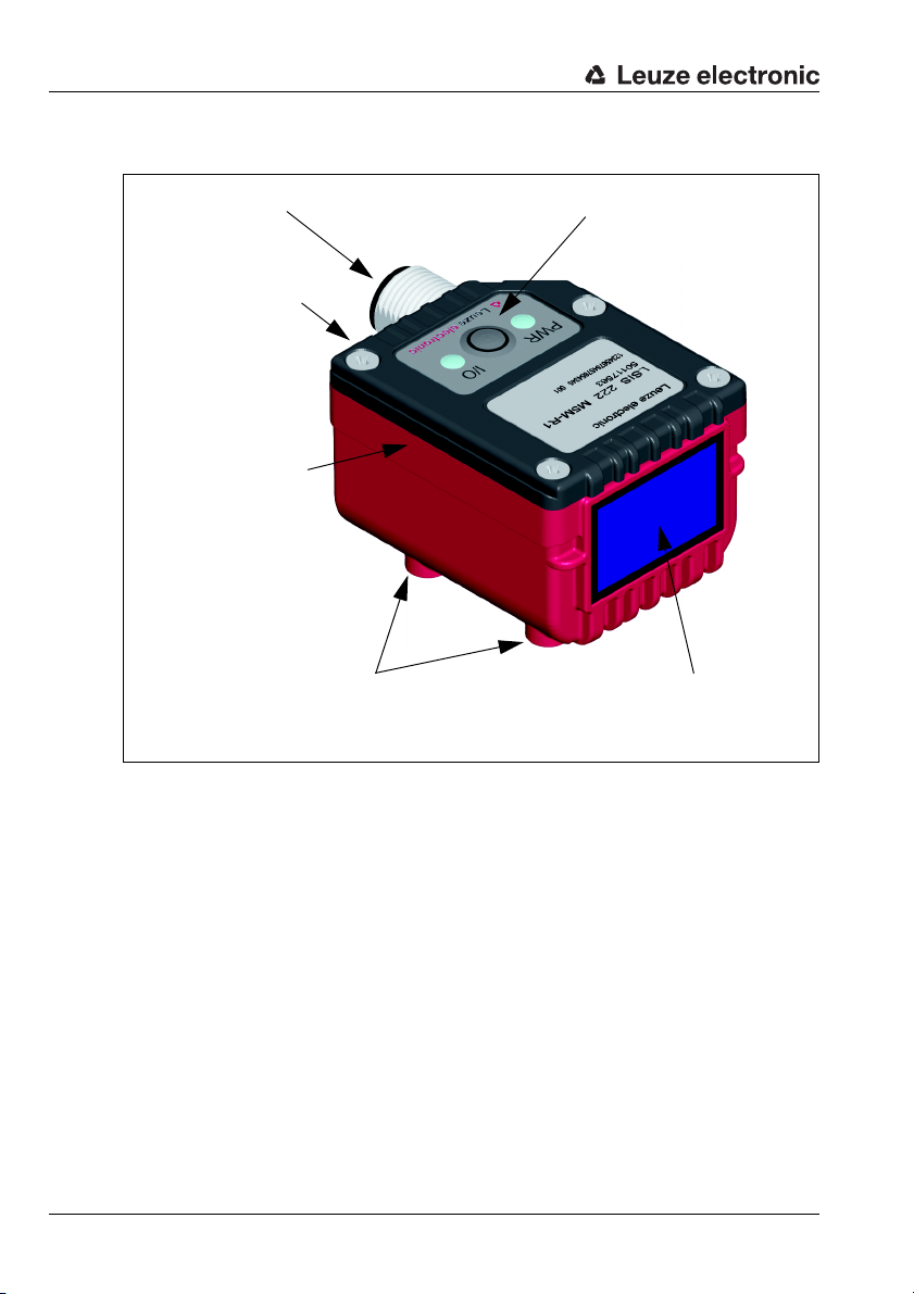
LEDs and buttons
Reading window with
LED illumination
and aimer
4 mounting threads below
Dovetail mounts and
2 mounting threads on
the rear
M12 connection technology
2 dovetail mounts on the
left and right side
3.3 Device construction
14 Technical description LSIS 22x Leuze electronic
Figure 3.5: Device construction
Page 17
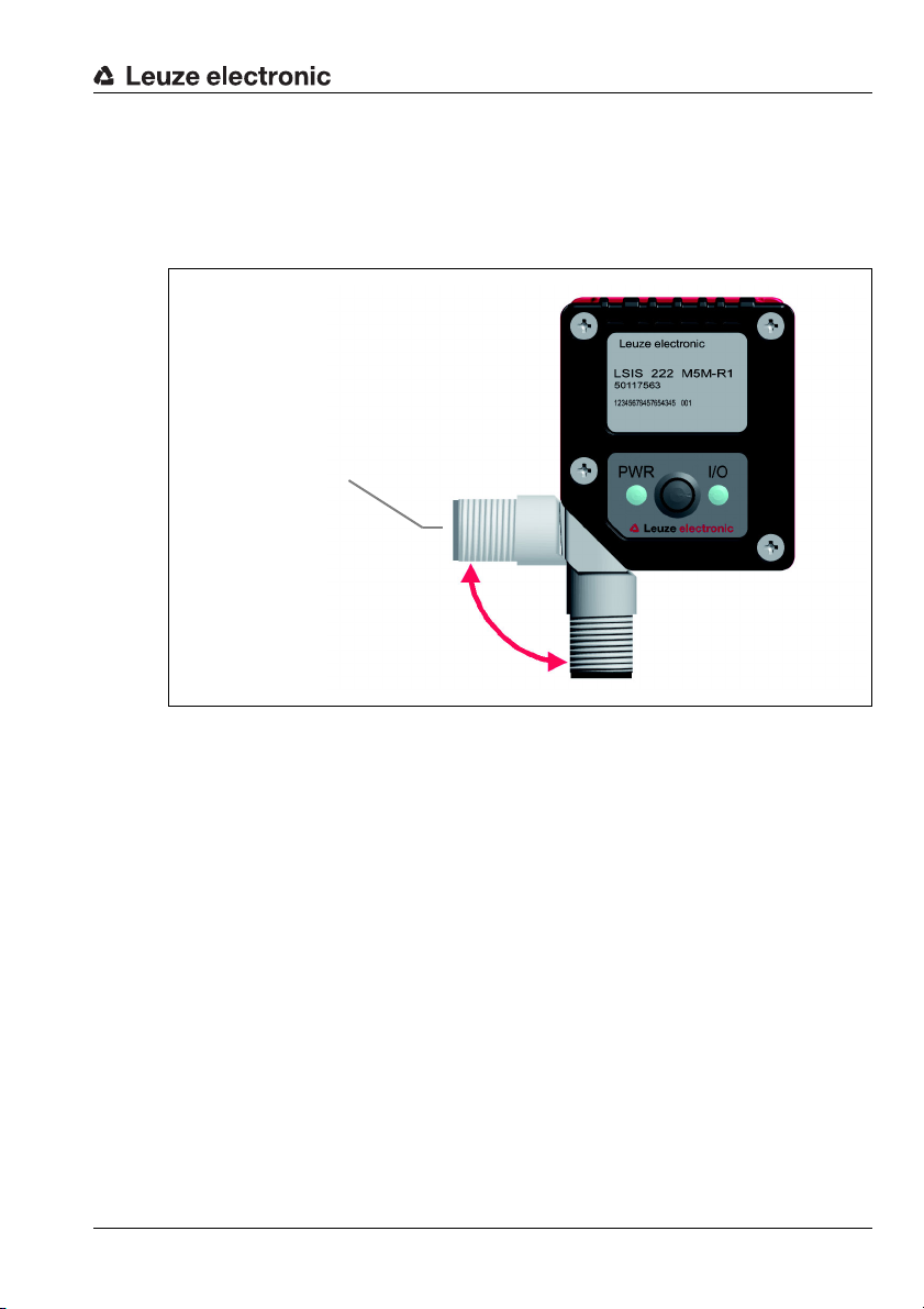
3.4 Stand-alone connection
Turning connector, turnable by 90°
Host interface (RS 232 or USB),
supply voltage + 2 I/O
The code readers of the LSIS 22x series can be operated as individual "stand alone"
devices. The LSIS 22x features an 8-pin M12 connector for the electrical connection of the
supply voltage, the interface and the switching input and output. The connector can be
turned 90°, thereby allowing cables to be laid optimally even in constrained spaces.
Device description
Figure 3.6: Stand-alone connection
Typically, the configuration codes are used to configure the LSIS 22x. Configuration via
online commands is also possible.
The switching input and output are used for reading-gate control and for signaling
successful reading.
The LSIS 22x can exchange data with the host computer via the RS 232 or USB interface.
The framing protocol used for this purpose can be adapted to the specific application. With
the USB interface, keyboard emulation is also possible.
Leuze electronic Technical description LSIS 22x 15
TNT 35/7-24V
Page 18
Installation and mounting
4 Installation and mounting
4.1 Storage, transportation
Attention!
When transporting or storing, package the device so tha t it is pro tected against collision and
humidity. Optimal protection is achieved when using the original packaging. Heed the
required environmental conditions specified in the technical data.
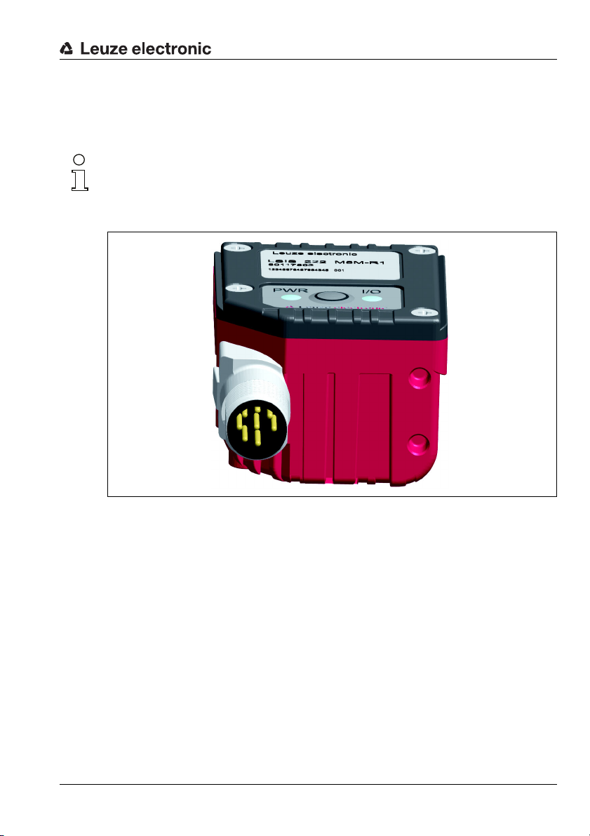
Unpacking
Check the packaging for any damage. If damage is found, notify the post office or ship-
ping agent as well as the supplier.
Check the delivery contents using your order and the delivery papers:
• Delivered quantity
• Device type and model as indicated on the name plate
•Package insert
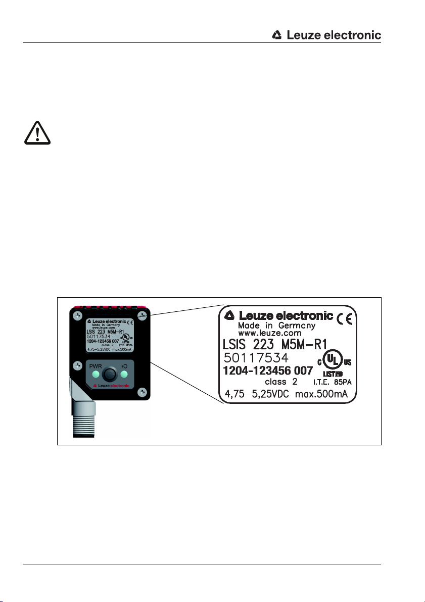
The name plate provides information as to what LSIS type your device is. For specific information, please refer to chapter 10.
Name plates of the code readers of the LSIS 22x series
Figure 4.1: Device name plate LSIS 22x
Save the original packaging for later storage or shipping.
If you have any questions concerning your shipment, please contact your supplier or your
local Leuze electronic sales office.
Observe the applicable local regulations when disposing of the packaging materials.
16 Technical description LSIS 22x Leuze electronic
Page 19
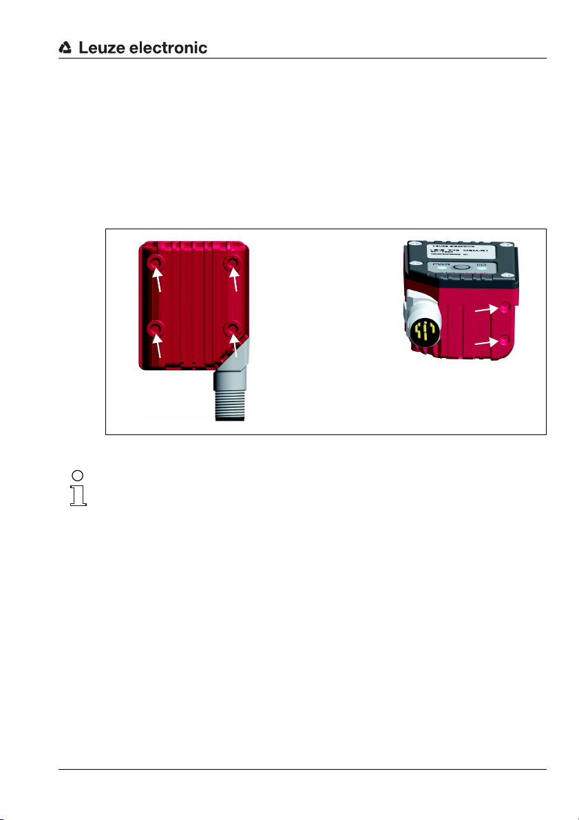
4.2 Mounting the LSIS 22x
M4, thread depth 3.5mm
The LSIS 22x code readers can be mounted in various ways:
• Via four M4 mounting threads on the bottom of the device
• Via two M4 mounting threads on the rear side of the device
• Via three dovetail mounts on the housing sides and the sensor back.
Appropriate mounting devices are available for all types of fastening.
4.2.1 Fastening with M4 screws
Figure 4.2: Fastening options using M4 threaded holes
Installation and mounting
Notice!
Dimensioned drawing can be found in chapter 12.2 on page 82.
Leuze electronic Technical description LSIS 22x 17
TNT 35/7-24V
Page 20
Installation and mounting
Clamped holding device
for dovetail fitting of the
LSIS 22x
All dimensions in mm
Dovetail fitting
of the LSIS 22x
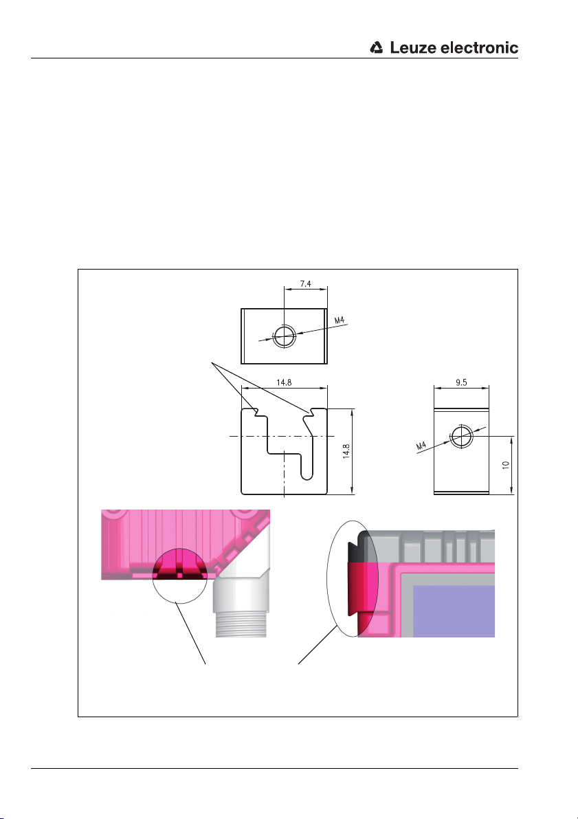
4.2.2 Mounting devices
The following mounting devices are available for fastening the LSIS 22x to the dovetail
fittings:
• BT 8-0 mounting block for dovetail (part no. 50036196)
• BTU 300M - D10 through hole fastening for rod D = 10 mm or cheek 1.5 … 4mm
• BTU 300M - D12 through hole fastening for rod D = 12 mm or cheek 1.5 … 4mm
• BTU 300M - D14 through hole fastening for rod D = 14 mm or cheek 1.5 … 4mm
BT 8-0 mounting device
(part no. 50117253)
(part no. 50117252)
(part no. 50117251)
Figure 4.3: BT 8-0 mounting device
18 Technical description LSIS 22x Leuze electronic
Page 21
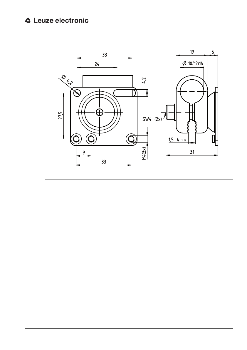
BTU 300M - D… mounting device
All dimensions in mm
Figure 4.4: BTU 300M - D… mounting device
Installation and mounting
4.3 Device arrangement
4.3.1 Selecting a mounting location
In order to select the right mounting location, several factors must be considered:
• The reading distance resulting from the code size and code type (see figure 4.5).
• The permissible cable lengths between the LSIS 22x and the host system depending
on which interface is used.
• The control panel with LEDs and trigger button should be very visible and
accessible.
• Mount the LSIS 22x so that the codes that are to be read are not exposed to direct
sunlight or strong ambient light.
When selecting a mounting location, pay further attention to:
• Maintaining the required environmental conditions (temperature, humidity).
• Possible soiling of the viewing window due to liquids, abrasion by boxes, or
packaging-material residues.
• Lowest possible chance of damage to the LSIS 22x by mechanical collision or
jammed parts.
Leuze electronic Technical description LSIS 22x 19
TNT 35/7-24V
Page 22
Installation and mounting
10 Mil (0.
254
mm) Code 128
0 100 200 30050 150 250 350 400
2D-Codes
1D-Codes
20 Mil (0.508 mm) Data Matrix Code
10 Mil (0.254 mm) Data Matrix Code
13 Mil (0.330 mm) UPC-A / EAN-13
Reading distance [mm]
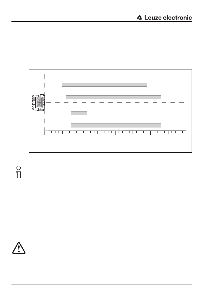
4.3.2 Determining the reading distance
The typical reading distances are shown in figure 4.5.
In general, the read field increases with the reading distance. This also results in a decrease
in the resolution, however.
For reading distances between 100 mm and 130 mm, particularly homogeneous illumination of the image field is ensured by the integrated illumination.
Figure 4.5: Reading distance as a function of resolution/code type
Notice!
Please notice that the real reading distances are also influenced by factors such as labeling
material, printing quality, scanning angle, printing contrast etc., and may thus deviate from
the reading distances specified here.
Depending on code type, code size, cell or modulus size and position of the code in the
field of view, reading can also occur while in motion.
4.4 Cleaning
Clean the housing window of the LSIS 22x with a soft cloth after mounting. Remove all
packaging remains, e.g. carton fibers or Styrofoam balls. In doing so, avoid leaving
fingerprints on the front cover of the LSIS 22x.
Attention!
Do not use aggressive cleaning agents such as thinner or acetone for cleaning the device.
Use of improper cleaning agents can damage the housing window and display.
20 Technical description LSIS 22x Leuze electronic
Page 23
5 Electrical connection
The code readers of the LSIS 22x series are connected using an 8-pin, A-coded M12
connector.
Notice!
Ready-made cables are provided for the 8-pin M12 connection.
See "Ready-made cable accessories" on page 78.
For order codes, see chapter 10.3 on page 78.
Electrical connection
Figure 5.1: Location of the electrical connection
Leuze electronic Technical description LSIS 22x 21
TNT 35/7-24V
Page 24
Electrical connection
5.1 Safety notices for the electrical connection
Attention!
Do not open the device yourself under any circumstances! The housing of the LSIS 22x contains no parts that need to be adjusted or maintained by the user.
Before connecting the device please ensure that the supply voltage matches the value printed on the nameplate.
Connection of the device and cleaning must only be carried out by a qualified electrician.
Ensure that the functional earth (FE) is connected correctly. Unimpaired operation is only
guaranteed when the functional earth is connected properly.
If faults cannot be corrected, the device should be removed from operation and protected
against possible commissioning.
Attention!
For UL applications, use is only permitted in class 2 circuits in accordance with the NEC
(National Electric Code).
The code readers of the LSIS 22x series are designed in accordance with safety class III for
supply by PELV (protective extra-low voltage).
Notice!
Protection class IP 65 is only achieved with screwed-on connector!
22 Technical description LSIS 22x Leuze electronic
Page 25
5.2 Electrical connection of the LSIS 22x M5M-R1
PIN
Signal
3
LSIS 223LSIS 222
GNDIN
USBRS232
1 Vin 10 … 30 V DC
VB 4.75
…
5.25 V DC
2 SWI
SWI
GND
4 SWO SWO
5 not connected not connected
6 RXD - Data D+ - Data
7 TXD - Data D
-
- Data
8 FE - Shield FE - Shield
SH FE - Shield FE - Shield
M12, 8-pole
male, A-cod.
M12 plug
8-pin
(A-coded)
The LSIS 22x is equipped with an A-coded M12 connector.
•The voltage supply (10 … 30VDC) is connected at pin 1 and pin 3 (VB, GND).
•The switching input is connected at pin 2 (SWI).
•The switching output is connected at pin 4 (SWO).
•The RS 232 interface is the host interface of the LSIS 222 M5M-R1.
It is connected at pin 6 and pin 7 (TXD - data, RXD - data).
•The USB interface is the host interface of the LSIS 223 M5M-R1.
It is connected at pin 6 and pin 7 (D+ - data, D– - data).
Electrical connection
Leuze electronic Technical description LSIS 22x 23
Figure 5.2: Connections of the LSIS 22x
Described in detail in the following are the individual connections.
Attention!
Ensure that the functional earth (FE) is connected correctly. Unimpaired operation is only
guaranteed when the functional earth is connected properly.
Preferably, use the ready-made connection cables from Leuze electronic (see chapter 10.3
on page 78).
Supply voltage
Attention!
For UL applications, use is only permitted in class 2 circuits in accordance with the NEC
(National Electric Code).
The code readers of the LSIS 22x … series are designed in accordance with safety class III
for supply by PELV (protective extra-low voltage).
TNT 35/7-24V
Page 26

Electrical connection
Switching input
5 V DC (LSIS 223 M5M-R1)
10…30 V DC (LSIS 222 M5M-R1)
LSIS 22x
SWO
VB
GND
max. 20 mA !
Switching output
Connecting functional earth FE
Attention!
Ensure that the functional earth (FE) is connected correctly. Unimpaired operation is only
guaranteed when the functional earth is connected properly. All electrical disturbances
(EMC couplings) are discharged via the functional earth connection.
Switching input/output
The LSIS 22x code readers are equipped with both an opto-decoupled SWI switching input
and SWO switching output.
The LSIS 22x can be activated with the switching input (triggering of code reading).
The switching output is used to signal 'good read' read processes. If a read process is
successful, a high pulse lasting 80 ms is output at the switching output.
External wiring of the switching input
10…30 V DC (LSIS 222 M5M-R1)
5 V DC (LSIS 223 M5M-R1)
VB
SWI
GND
LSIS 22x
Figure 5.3: External wiring of the switching input
External wiring of the switching output
Figure 5.4: External wiring of the switching output
Attention!
24 Technical description LSIS 22x Leuze electronic
The switching output is short-circuit proof! However, do not load the switching output of
the LSIS 22x with more than 20mA in normal operation!
Page 27

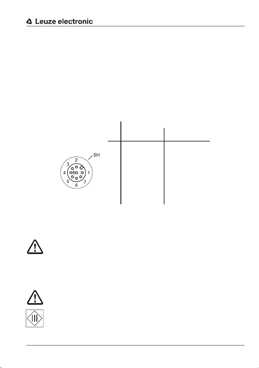
5.2.1 LSIS 222 M5M-R1 - RS 232 interface
SWI
SWOVB
n. c.
RXD
TXD
GNDFE
7
Host
GND
FE
Tx
Rx
up to 10m!
shield
The RS 232 interface is used primarily for outputting the read and decoded code contents
of the activated code types.
Notice!
Preferably, use the ready-made connection cables from Leuze electronic (see chapter 10.3
on page 78).
Attention!
Observe the maximum cable length of 10m!
If using self-made cables, observe the following notice:
Notice for connecting the RS 232 interface!
Ensure adequate shielding. The entire connection cable must be shielded and earthed.
RS 232 cable assignments
Electrical connection
Figure 5.5: RS 232 pin assignments
MA 2 / MA 4… / MA 2xxi modular interfacing units
To convert the RS 232 to other interfaces (RS 485, RS 422, …) or to connect to fieldbus
systems (PROFIBUS, PROFINET, Ethernet, etc.), an entire series of Leuze connector units
are available .
The KB JST-M12A-8P-3000 system connection cable (part no. 50111225) can be used to
directly connect the LSIS 222 M5M-R1 to these connector units.
Leuze electronic Technical description LSIS 22x 25
TNT 35/7-24V
Page 28

Electrical connection
SWI
SWOVB
n. c.
D+ Data
D
-
Data
GNDFE
7
Host
4
SH
1
3
2
GND
VB
D+
D
-
rt/RD
ws/WH
gn/GN
sw/BK
up to 3m!
shield
5.2.2 LSIS 223 M5M-R1 - USB interface
The USB interface is used primarily for outputting the read and decoded code contents of
the activated code types.
Notice!
Preferably, use the ready-made connection cables from Leuze electronic (see chapter 10.3
on page 78).
Attention!
Observe the maximum cable length of 3m!
If using self-made cables, observe the following notice:
Notice for connecting the USB interface!
Ensure adequate shielding. The entire connection cable must be shielded and earthed. Use
only full-/high-speed data lines acc. to USB 2.0 specifications.
USB cable assignments
Figure 5.6: USB pin assignment
26 Technical description LSIS 22x Leuze electronic
Page 29

6 Commissioning
6.1 Starting the LSIS 222 M5M-R1 - RS 232 interface
Connect the voltage supply and, if applicable, the switching input and the serial interface
as described in chapter 5.
Notice!
For the host and LSIS 222 to be able to communicate with one another, the interface
parameters (transmission rate, data format) must match!
Factory setting LSIS 222:
• 9600 baud
• 8 data bits
•no parity
•1 stop bit
Set the host interface to the same parameters as the LSIS 222 or set the LSIS 222 to the
same parameters as the host (see chapter 7.1 "Configuration of interface").
Start the Leuze operating software BCLconfig on the connected host (PC/terminal) and call
up the terminal function.
Connect the +10 … +30V DC supply voltage (typ. +24VDC).
The LSIS 222 starts up; readiness for operation is indicated by the illumination of the green
PWR LED.
By default, the LSIS 222 is in manual trigger mode after switching on for the first time.
Press and hold down the trigger button or apply a high signal to the SWI switching input to
now activate the code reader (reading gate open). Further information on possible operating modes can be found in chapter 7.1 on page 30.
Hold a sample code in front of the LSIS 222 at a distance of approx. 100mm (see chapter
13.3 "Sample codes" in the appendix). If the read operation is successful, the green alignment aid and red illumination are switched off. The read result is displayed on the screen.
Close the reading gate by releasing the trigger button or, if applied, removing the high
signal at the SWI switching input.
Commissioning
TNT 35/7-24V
Leuze electronic Technical description LSIS 22x 27
Page 30

Commissioning
6.2 Starting the LSIS 223 M5M-R1 - USB-interface
USB keyboard emulation
Connect the voltage supply and, if applicable, the switching input and the USB interface as
described in chapter 5.
Start the display software (e.g., Editor) on the connected host (PC/terminal).
Connect the +4.75 … +5.25 V DC supply voltage (typ. +5 V DC). A Windows driver is
installed.
The LSIS 223 starts up; readiness for operation is indicated by the illumination of the green
PWR LED.
By default, the LSIS 223 is in streaming presentation mode (permanent reading) after
switching on for the first time; illumination is activated. Further information on possible
operating modes can be found in chapter 7.2 on page 37.
Hold a sample code in front of the LSIS 223 at a distance of approx. 100mm (see chapter
13.3 "Sample codes" in the appendix). If the read operation is successful, the I/O LED
briefly illuminates green for 80ms. The read result is displayed on the screen.
The LSIS 223 is then immediately again ready for further code readings. The reading gate
remains open.
Notice!
With USB keyboard emulation, data can only be sent in one direction: from the LSIS 22x to
the host.
USB COM port emulation
You can optionally operate the LSIS 223 in the USB COM port emulation operating mode
without considerable configuration effort. You can then operate the code reader with the
BCLconfig software; data can be sent bidirectionally.
First install the USB COM port driver for the LSIS 223, which you can download from the
Leuze home page www.leuze.com
"Configuration code for USB COM port emulation" on page 33.
. Then simply read in the configuration code in figure 7.5
6.3 Operating modes
The LSIS 22x can be configured for various operating modes.
• Manual/serial trigger mode
• Presentation mode
• Streaming presentation mode
Notice!
The description of the operating modes and instructions on configuring them can be found
in chapter 7.2 "Configuration of the reading gate control (trigger)" on page 34.
28 Technical description LSIS 22x Leuze electronic
Page 31

6.4 LED indicators
The LSIS 22x has two LEDs, PWR and I/O.
Figure 6.1: LEDs of the LSIS 22x
The LEDs have the following function:
PWR LED
off Device OFF
green continuous light Readiness for operation
I/O LED
Commissioning
-No supply voltage
- Code reading possible
- Self test successfully finished
green, briefly on (80ms) Good read, successful reading
- Code reading successful
continuous red light Reading gate open
- Code reading active
off No supply voltage
-No communication possible
Leuze electronic Technical description LSIS 22x 29
TNT 35/7-24V
Page 32
Configuration using configuration codes
7 Configuration using configuration codes
The LSIS 22x is configured with the aid of configuration codes. After reading in these
codes, the device parameters are set in the device and permanently stored.
Notice!
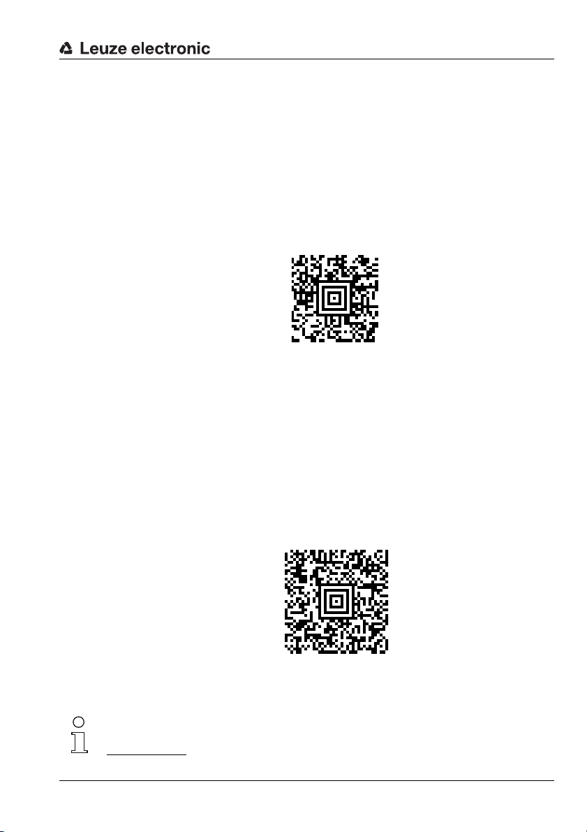
Using Aztec configuration codes, many parameters can be set simultaneously; using
1-dimensional configuration codes, on the other hand, it is generally only possible to set
individual parameters.
7.1 Configuration of interface
7.1.1 RS 232 parameter - LSIS 222 M5M-R1
By reading in the following configuration code, the RS 232 interface is set to the following
standard parameters (factory settings):
•Baud rate 9600bit/s
• Data format 8 data bits, no parity, 1 stop bit
•Framing <STX>DATA<CR><LF>
• No read character ’?’
• Manual trigger mode start command: <SYN>T<CR>
stop command: <SYN>U<CR>
Figure 7.1: Configuration code RS 232 standard parameters
Notice!
The LSIS 222 M5M-R1 and the connected host must be set to the same interface parameters.
30 Technical description LSIS 22x Leuze electronic
Page 33
Configuration using configuration codes
300 bit/s
600 bit/s
1.2 kbit/s
2.4 kbit/s
4.8 kbit/s
9.6 kbit/s
19.2 kbit/s
38.4 kbit/s
57.6 kbit/s
115.2 kbit/s
By reading in one of the following configuration codes, the RS 232 baud rate can be set.
Baud rates from 300 bit/s … 115.2 kbit/s are available.
Figure 7.2: Configuration codes RS 232 baud rate
Leuze electronic Technical description LSIS 22x 31
TNT 35/7-24V
Page 34
Configuration using configuration codes
7 data bits, even parity, 1 stop bit
7 data bits, no parity, 1 stop bit
7 data bits, odd parity, 1 stop bit
7 data bits, even parity, 2 stop bits
7 data bits, no parity, 2 stop bits
7 data bits, odd parity, 2 stop bits
8 data bits, even parity, 1 stop bit
8 data bits, no parity, 1 stop bit
8 data bits, odd parity, 1 stop bit
By reading in one of the following configuration codes, the RS 232 data format can be set.
Figure 7.3: Configuration codes RS 232 data format
Notice!
For further RS 232 settings, please contact Leuze electronic.
32 Technical description LSIS 22x Leuze electronic
Page 35
Configuration using configuration codes
7.1.2 USB parameter - LSIS 223 M5M-R1
By reading in the following configuration code, the USB interface is set to the following
standard parameters for USB keyboard emulation (factory setting):
•USB operating mode USB keyboard emulation
• Keyboard layout GERMAN
•Framing ’ENTER’
• No read character none
•Streaming presentation mode
Figure 7.4: Configuration code USB standard parameters (keyboard emulation)
As an alternative to USB keyboard emulation, USB COM port emulation is also possible
with the following parameters:
•Framing <STX>DATA<CR><LF>
• No read character ’?’
• Manual trigger mode start command: <SYN>T<CR>
Please read in the following configuration code to set these parameters.
stop command: <SYN>U<CR>
Figure 7.5: Configuration code for USB COM port emulation
Notice!
The Windows driver for USB COM port emulation can be found in the download area at
www.leuze.com
Leuze electronic Technical description LSIS 22x 33
.
TNT 35/7-24V
Page 36
Configuration using configuration codes
7.2 Configuration of the reading gate control (trigger)
Multiple trigger modes are available for controlling the reading gate (start/stop reading):
• Manual/serial trigger mode
(factory setting for RS 232 and USB COM port)
With manual/serial trigger mode, the reading gate opens if the trigger button is
pressed, the trigger input is activated by applying a high signal, or if the
<SYN>T<CR> read start command is sent to the LSIS 22x via the serial interface.
The reading gate closes if a code is read successfully, the trigger button released,
the trigger input deactivated by removing the high signal, or if the <SYN>U<CR>
read stop command is sent to the LSIS 22x via the serial interface.
With serial trigger (trigger commands via the serial interface), a read time-out time
can optionally be set, after which the reading gate is closed if no code was read.
• Presentation mode
In presentation mode, the LSIS 22x is set to permanent reading for ambient light.
The reading gate is continuously open. If a change in the image area is detected, the
LSIS 22x first tries to read a code. If this is not successful, the intensity of the LED
illumination is continuously increased until a code is read. Following the successful
reading of a code, the LED illumination is switched off again after a few seconds.
• Streaming presentation mode
(factory setting for USB keyboard emulation)
In streaming presentation mode, the LSIS 22x is set to permanent reading with permanently switched-on LED illumination. The reading gate is continuously open.
Normal / enhanced mode
With manual/serial trigger mode and with streaming presentation mode, a distinction
is also made between the normal and enhanced settings:
•The normal setting (factory setting) offers good reading speed at maximum operat-
ing range.
•The enhanced setting, on the other hand, offers maximum reading speed at a
slightly reduced operating range.
Notice!
If in doubt, test which setting, normal or enhanced, delivers the best results in your application.
34 Technical description LSIS 22x Leuze electronic
Page 37
7.2.1 Manual/serial trigger mode
Manual/serial trigger mode - normal
Manual/serial trigger mode - enhanced
Read time-out
By reading in one of the following configuration codes, the manual/serial trigger mode is
set to either the normal or enhanced variant.
Figure 7.6: Configuration codes for setting the manual/serial trigger mode
Read time-out for serial trigger
If the reading gate is to be closed after sending the <SYN>T<CR> read start command if
no code was read after a defined time, you can set a read time-out time. Values can be
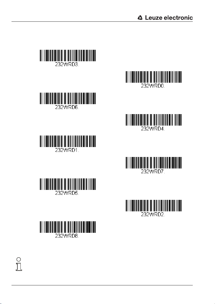
set in the range 0 … 300,000ms.
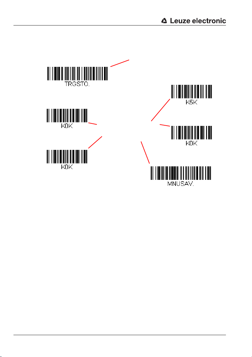
To do this, first read in the following configuration code and then, digit by digit, the
programming codes (see "Programming codes for the configuration" on page 92) for the
numerical value of the read time-out time in milliseconds. Conclude parameter entry by
reading in the Save programming code.
Configuration using configuration codes
Figure 7.7: Configuration code for setting the read time-out time
Shown below is an example illustrating the principle for entering a parameter value.
Leuze electronic Technical description LSIS 22x 35
TNT 35/7-24V
Page 38
Configuration using configuration codes
1. Read time-out
2. Digit ’5’
3. Digit ’0’
4. Digit ’0’
5. Digit ’0’
6. SAVE
"Programming codes for
the configuration" on
page 92
Configuration code
’read time-out’
Example: Setting a read time-out time of 5 seconds = 5000 ms.
Read in the following codes in the specified order to set the time.
Figure 7.8: Example: Setting a read time-out time of 5 seconds
36 Technical description LSIS 22x Leuze electronic
Page 39
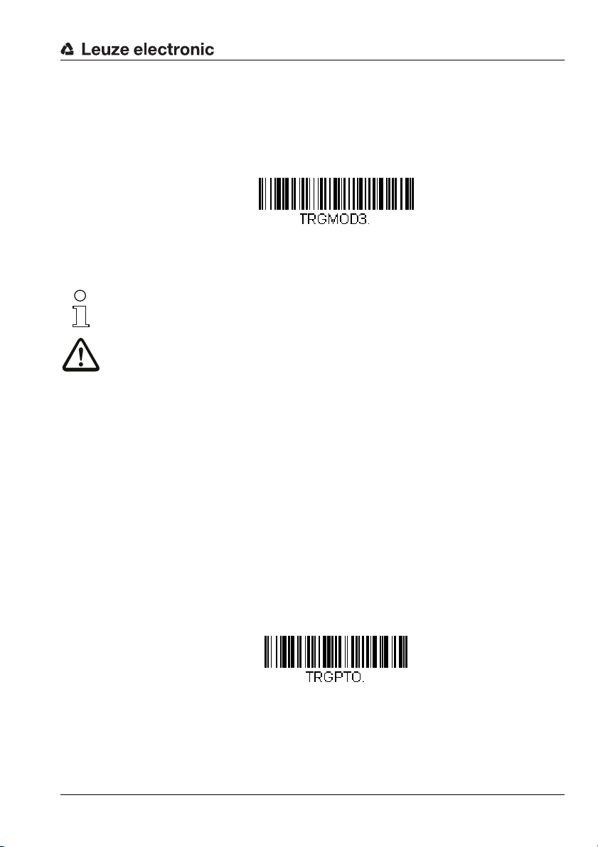
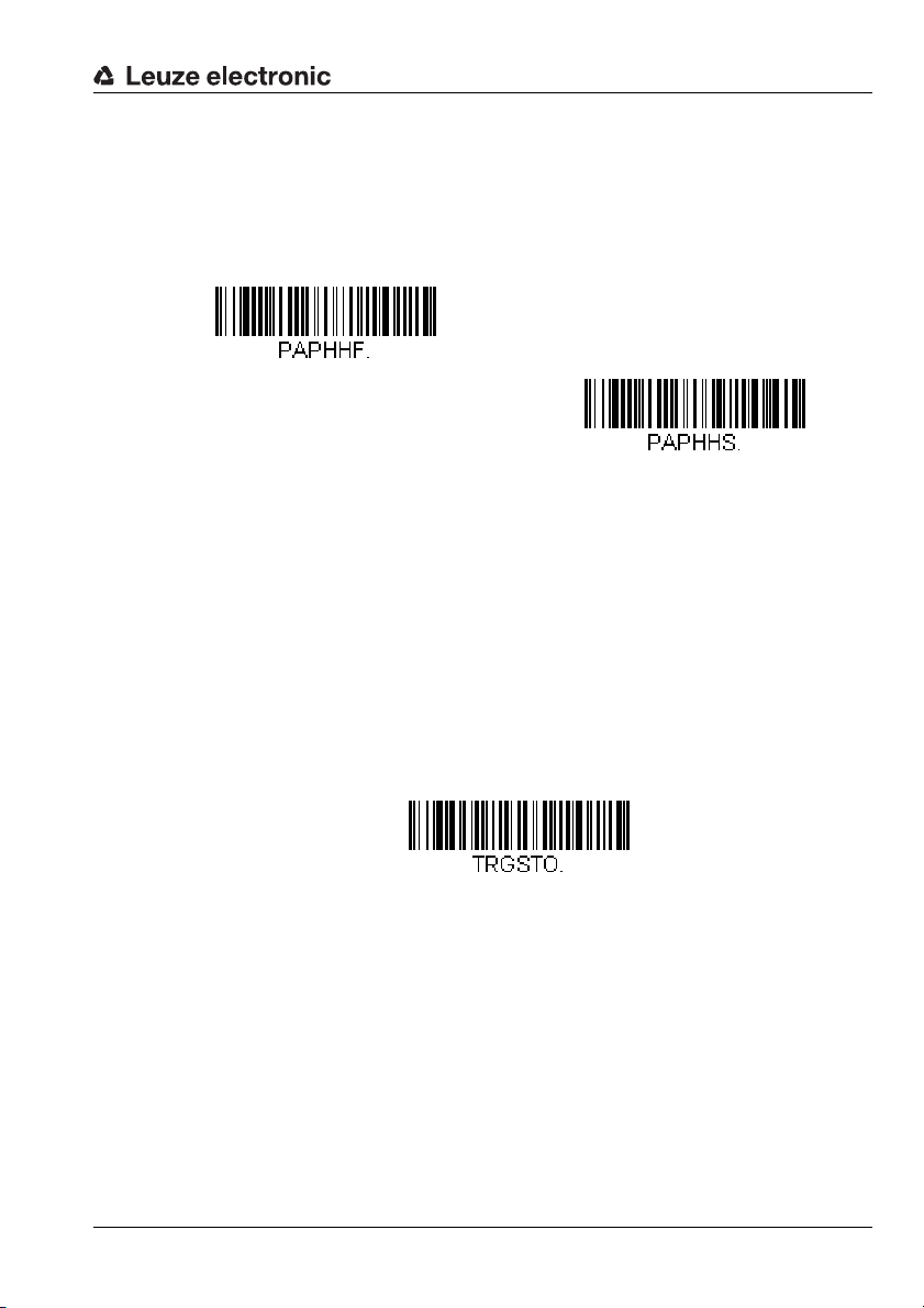
7.2.2 Presentation mode
Presentation mode
Hands free time-out
By reading in the following configuration code, presentation mode is set.
Figure 7.9: Configuration code for setting the presentation mode
Notice!
For further optional settings on this parameter, please contact Leuze electronic.
Attention!
If a trigger occurs by means of a button or trigger input while the LSIS 22x is in
presentation mode, the LSIS 22x switches to manual/serial trigger mode!
Each time the trigger button is pressed or trigger input is activated, the LSIS 22x is again
activated as long as the trigger button is pressed or a high-signal is applied at the trigger
input.
If no trigger is initiated via the button or the switching input for the duration of the hands
free time-out time (factory setting: 5s), the LSIS 22x returns to presentation mode.
In manual/serial trigger mode, the hands free time-out time is not active.
Configuration using configuration codes
Configuring the hands free time-out time
First read in the following configuration code and then, digit by digit, the programming
codes (see "Programming codes for the configuration" on page 92) for the numerical value
of the hands free time-out time in milliseconds. Conclude parameter entry by reading in the
Save programming code.
Values can be set in the range 0 … 300,000ms (factory setting: 5000 ms) .
Figure 7.10: Configuration code for setting the hands free time-out time
Leuze electronic Technical description LSIS 22x 37
TNT 35/7-24V
Page 40
Configuration using configuration codes
Streaming presentation mode - normal
Streaming presentation mode - enhanced
7.2.3 Streaming presentation mode
By reading in one of the following configuration codes, streaming presentation mode is
set to either the normal or enhanced variant.
Figure 7.11: Configuration codes for setting the streaming presentation mode
Attention!
If a trigger occurs by means of a button or trigger input while the LSIS 22x is in
presentation mode, the LSIS 22x switches to manual/serial trigger mode!
Each time the trigger button is pressed or trigger input is activated, the LSIS 22x is again
activated as long as the trigger button is pressed or a high-signal is applied at the trigger
input.
If no trigger is initiated via the button or the switching input for the duration of the hands
free time-out time (factory setting: 5s), the LSIS 22x returns to presentation mode.
In manual/serial trigger mode, the hands free time-out time is not active.
See "Configuring the hands free time-out time" on page 37.
38 Technical description LSIS 22x Leuze electronic
Page 41
Configuration using configuration codes
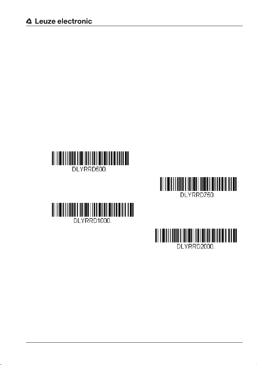
Short = 500ms
Medium = 750ms
Long = 1000ms
Extra long = 2000ms
7.3 Configuration of the reading properties
7.3.1 Reading the same code multiple times
To prevent the same code from being repeatedly read and output in presentation mode, a
reread delay delay time can be configured that must elapse before the same code can be
read again.
By default, four preset times are available for selection for reread delay:
• Short = 500ms
• Medium = 750ms
• Long = 1000ms
• Extra long = 2000ms
By reading in one of the following configuration codes, the reread delay time is set to the
corresponding value.
Figure 7.12: Configuration codes for setting the reread delay time
If these four preset times are not sufficient, you can define an application-specific time for
reread delay in the range from 0 … 30,000ms.
Leuze electronic Technical description LSIS 22x 39
TNT 35/7-24V
Page 42

Configuration using configuration codes
Application-specific reread delay time
Multiple read ON
Multiple read OFF
To do this, first read in the following code and then, digit by digit, the programming codes
(see "Programming codes for the configuration" on page 92) for the numerical value of the
reread delay time in milliseconds. Conclude parameter entry by reading in the Save
programming code.
Figure 7.13: Configuration code for setting the read time-out time
To illustrate the principle of parameter value entry, see example on page 36.
7.3.2 Reading multiple different codes in one reading gate
By activating the multiple read option, multiple codes can simultaneously be read in one
reading gate. The LSIS 22x attempts to find new codes in the read field as long as the
reading gate is open. If the option is deactivated (factory setting), the LSIS 22x reads the
code that is closest to the target beam and, thus, to the center of the read field.
By reading in one of the following configuration codes, the multiple read option is set on
or off.
Figure 7.14: Configuration codes for switching the multiple read option on/off
40 Technical description LSIS 22x Leuze electronic
Page 43

Configuration using configuration codes
Read field 844 x 640 pixels (gray)
Reading window
169 x 128 pixels
with the centering option active
Code 1
Code 2
Standard
position of the
reading window in
the read field
7.3.3 Restricting the read field (centering)
The read field of the LSIS 22x has a size of 844 x 640 pixels, shown above in figure 7.15 in
gray. If the centering option is activated, only codes that are partially or completely within
the reading window are read. Thus, code 2 in figure 7.15 is read but code 1 is not read.
Figure 7.15: Restricting the read field with the centering option
Leuze electronic Technical description LSIS 22x 41
TNT 35/7-24V
Page 44

Configuration using configuration codes
Centering ON
Centering OFF
By reading in one of the following configuration codes, the centering option is switched on
or off.
Figure 7.16: Configuration codes for switching the centering option on/off
Notice!
For a different size/position of the reading window within the read field, please contact
Leuze electronic.
42 Technical description LSIS 22x Leuze electronic
Page 45

Configuration using configuration codes
Only read inverted bar codes
Read inverted and
non-inverted bar codes
Read inverted bar codes OFF
VIDREV0.
7.3.4 Reading inverted bar codes (video reverse)
Activate the video reverse option to read inverted bar codes. When activating, you can
select whether only inverted codes or both inverted as well as non-inverted codes can be
read.
By reading in one of the following configuration codes, the video reverse option is
switched on or off.
Figure 7.17: Configuration code for switching the video reverse option on and off
Attention!
If you activate the option for only reading inverted bar codes, you can then no longer read
in any configuration codes. To again be able to read in configuration codes, please
deactivate the video reverse option by reading in the ’VIDREV0. code.
Notice!
2D-codes can always be read in both inverted and non-inverted, regardless of the video
reverse option.
Leuze electronic Technical description LSIS 22x 43
TNT 35/7-24V
Page 46

Configuration using configuration codes
Mobile phone read - manual trigger mode
Mobile phone read - streaming presentation mode
7.3.5 Reading codes on LED displays (mobile phone read mode)
The decoder of theLSIS 22x can be optimized to read codes on the display of mobile
devices such as smartphones or on other LED displays with reflective surfaces. If this
option is selected, printed codes may be decoded at a slightly reduced reading speed.
By reading in one of the following configuration codes, the mobile phone read mode
option in the manual trigger mode or streaming presentation mode trigger mode is
switched on.
To switch off this option, please read in the configuration code for the manual/serial
trigger mode in the normal or enhanced variant (see figure 7.6)
Figure 7.18: Configuration codes for switching-on the mobile phone read mode option
44 Technical description LSIS 22x Leuze electronic
Page 47

7.4 Configuring input / output
Delete all prefix characters
Set <STX> prefix
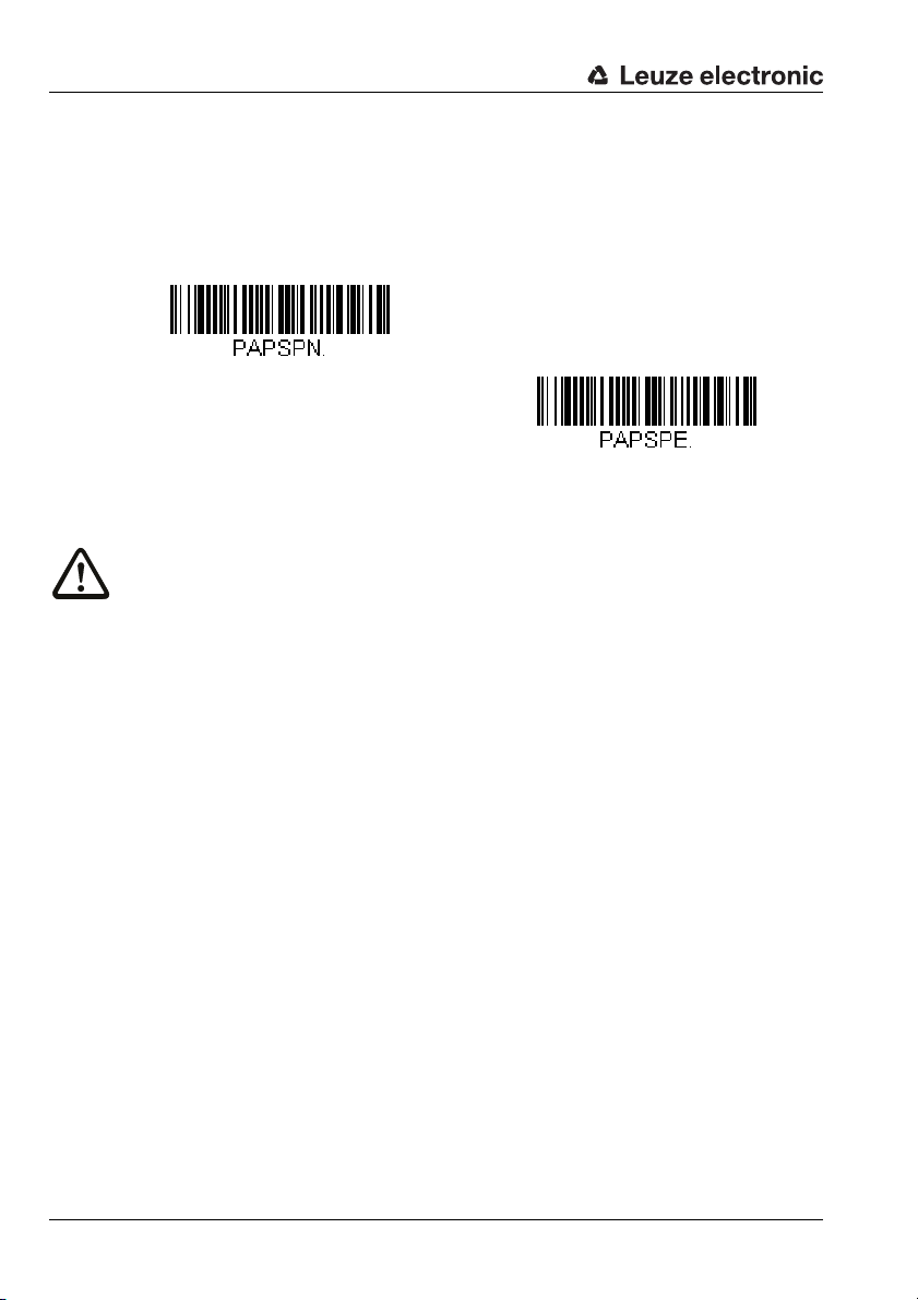
7.4.1 Prefix / suffix (framing)
For communication with the host, the read code information is contained in a message
string (frame format). With the LSIS 22x, the frame format has the following structure:
Prefix (1 … 11 ASCII characters) Decoded code content Suffix (1 … 11 ASCII characters)
For the prefix and the suffix, the following characters are preset at the factory for all code
types:
•Prefix: <STX>
• Suffix: <CR><LF>
You can set the prefix with the following configuration codes.
Configuration using configuration codes
Figure 7.19: Configuration codes for setting the prefix
Leuze electronic Technical description LSIS 22x 45
TNT 35/7-24V
Page 48
Configuration using configuration codes
Delete all suffix characters
Set <CR> suffix
Set <CR><LF> suffix
Set <ETX> suffix
Set <HT> suffix
Use the following configuration codes to set the suffix.
Figure 7.20: Configuration codes for setting the prefix
Notice!
With the LSIS 22x, an individual frame format can be defined for each code type. Further
information on this topic and on setting other prefix/suffix characters is available from Leuze
electronic.
46 Technical description LSIS 22x Leuze electronic
Page 49
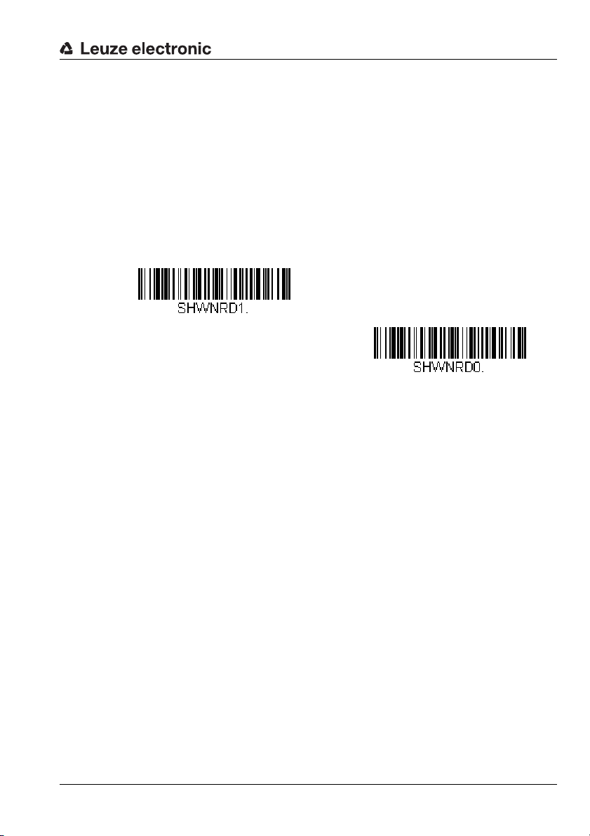
7.4.2 NoRead output
NoRead output ON
NoRead output OFF
You can set whether or not the ’NoRead’ character ’?’ is output i f a code could not be read.
Factory settings:
• LSIS 222 M5M-R1 (RS 232) NoRead output = ’?’
• LSIS 223 M5M-R1 (USB keyboard emulation) no NoRead output
• LSIS 223 M5M-R1 (USB COM port emulation) NoRead output = ’?’
By reading in one of the following configuration codes, the NoRead output option is
switched on or off.
Figure 7.21: Configuration code for switching the NoRead output option on/off
Configuration using configuration codes
Leuze electronic Technical description LSIS 22x 47
TNT 35/7-24V
Page 50
Configuration using configuration codes
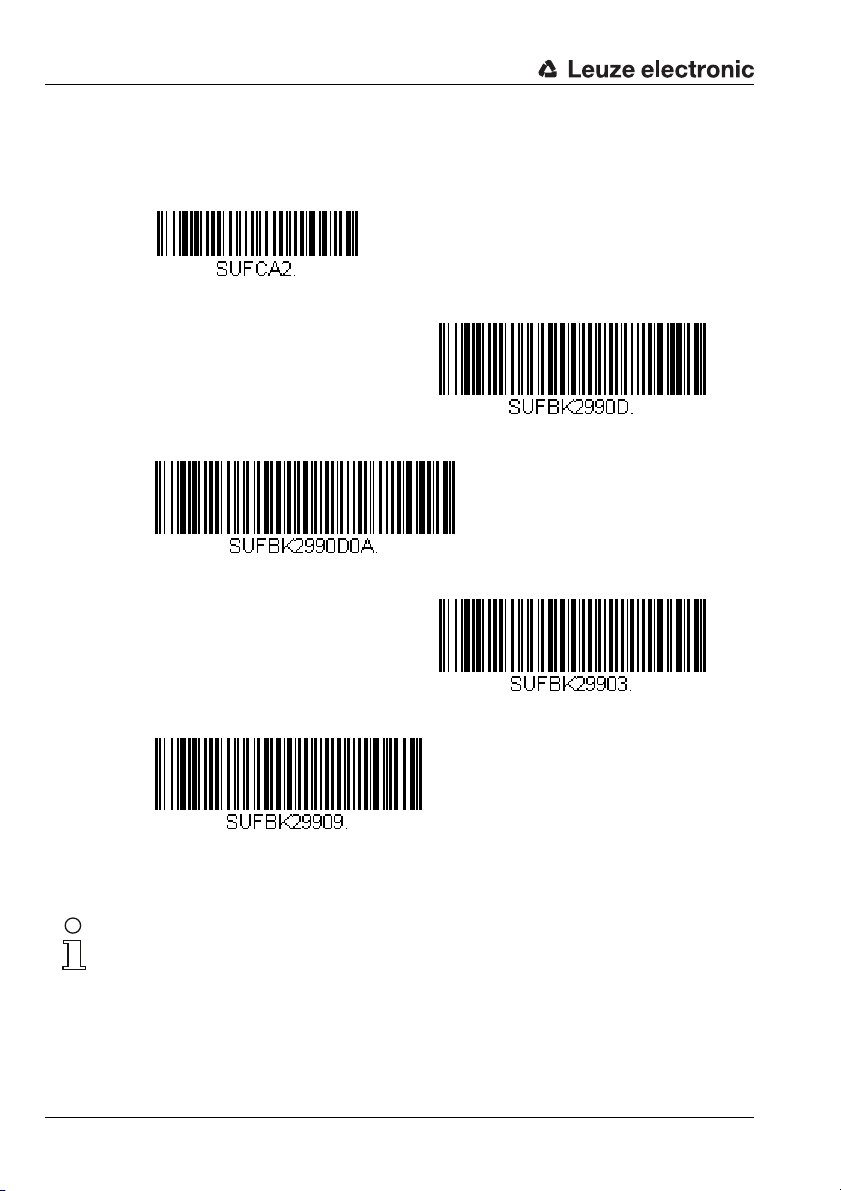
7.5 Configuring decoding (code selection)
The LSIS 22x supports nearly all common code types.
For each of the code types listed in the following, you can use configuration codes to individually set whether or not a given code type is to be decoded and output.
In addition, for some codes you can define that only codes with a configured number of
digits are output and whether check characters are to be output.
• All code types chapter 7.5.1 on page 49
• Codabar chapter 7.5.2 on page 50
• Code 39 chapter 7.5.3 on page 51
• Code 32 pharmaceutical (PARAF) chapter 7.5.4 onpage 53
• Interleaved 2/5 chapter 7.5.5 on page 54
• Code 93 chapter 7.5.6 on page 56
• Code 128 chapter 7.5.7 on page 57
• GS-1-128 chapter 7.5.8 on page 58
• UPC-A chapter 7.5.9 on page 59
• UPC-E chapter 7.5.10 on page 60
• UPC-E1 chapter 7.5.11 on page 60
• EAN/JAN-13 chapter 7.5.12 on page 61
• EAN/JAN-8 chapter 7.5.13 on page 62
• GS1 DataBar Omnidirectional chapter 7.5.14 on page 63
• GS1 DataBar Limited chapter 7.5.15 on page 63
• GS1 DataBar Expanded chapter 7.5.16 on page 64
• PDF417 chapter 7.5.17 on page 65
• MicroPDF417 chapter 7.5.18 on page 66
• GS1 Composite chapter 7.5.19 on page 67
• QR Code chapter 7.5.20 on page 68
• Data Matrix chapter 7.5.21 on page 69
• MaxiCode chapter 7.5.22 on page 70
• Aztec Code chapter 7.5.23 on page 71
Notice!
In addition to the common code types listed here, other code types can also be read. For
further information, please contact Leuze electronic.
48 Technical description LSIS 22x Leuze electronic
Page 51
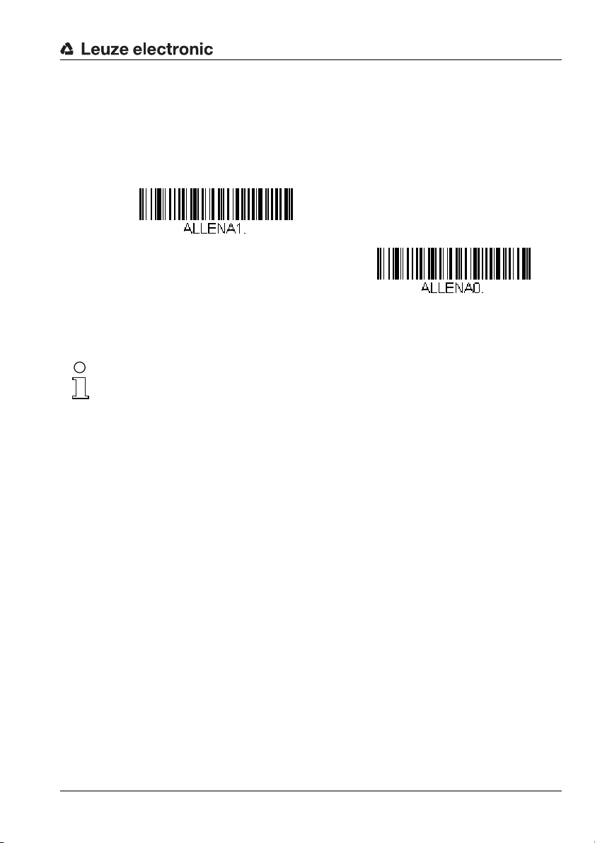
Configuration using configuration codes
read all code types ON
read all code types OFF
7.5.1 Code selection of all supported code types
By reading in one of the following configuration codes, reading of all code types listed in
section 7.5 is activated or deactivated.
Figure 7.22: Configuration codes for activating/deactivating all code types
Notice!
Other code types can be read on request.
For further information, please contact Leuze electronic.
Leuze electronic Technical description LSIS 22x 49
TNT 35/7-24V
Page 52
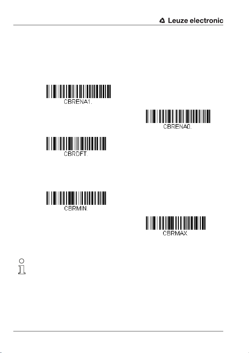
Configuration using configuration codes
Read code type Codabar ON
Read code type Codabar OFF
Codabar - standard settings
Codabar - minimum number of digits
Codabar - maximum number of digits
7.5.2 Codabar code selection
By reading in one of the following configuration codes, reading of the Codabar code type
is activated or deactivated. In addition, it is possible to configure the number of digits that
are to be read (value range for number of digits: 2 … 60, factory setting: 4 … 60).
Figure 7.23: Configuration codes for activating/deactivating the Codabar code type
Notice!
To set the minimum or maximum number of digits, please first read in the above configuration code and then the digits for the desired number of digits (see "Programming codes for
the configuration" on page 92). Conclude parameter entry by reading in the Save programming code.
For further code settings for the Codabar code type, please contact Leuze electronic.
50 Technical description LSIS 22x Leuze electronic
Page 53

7.5.3 Code 39 code selection
Read code type Code 39 ON
Read code type Code 39 OFF
Code 39 - standard settings
Code 39 - minimum number of digits
Code 39 - maximum number of digits
By reading in one of the following configuration codes, reading of the Code 39 code type
is activated or deactivated. In addition, it is possible to configure the number of digits that
are to be read (value range for number of digits: 0 … 48, factory setting: 0 … 48).
Also optionally configurable is the check-character evaluation and output.
Configuration using configuration codes
Figure 7.24: Configuration codes for activating/deactivating the Code 39 code type
Notice!
To set the minimum or maximum number of digits, please first read in the above configuration code and then the digits for the desired number of digits (see "Programming codes for
the configuration" on page 92). Conclude parameter entry by reading in the Save programming code.
Leuze electronic Technical description LSIS 22x 51
TNT 35/7-24V
Page 54
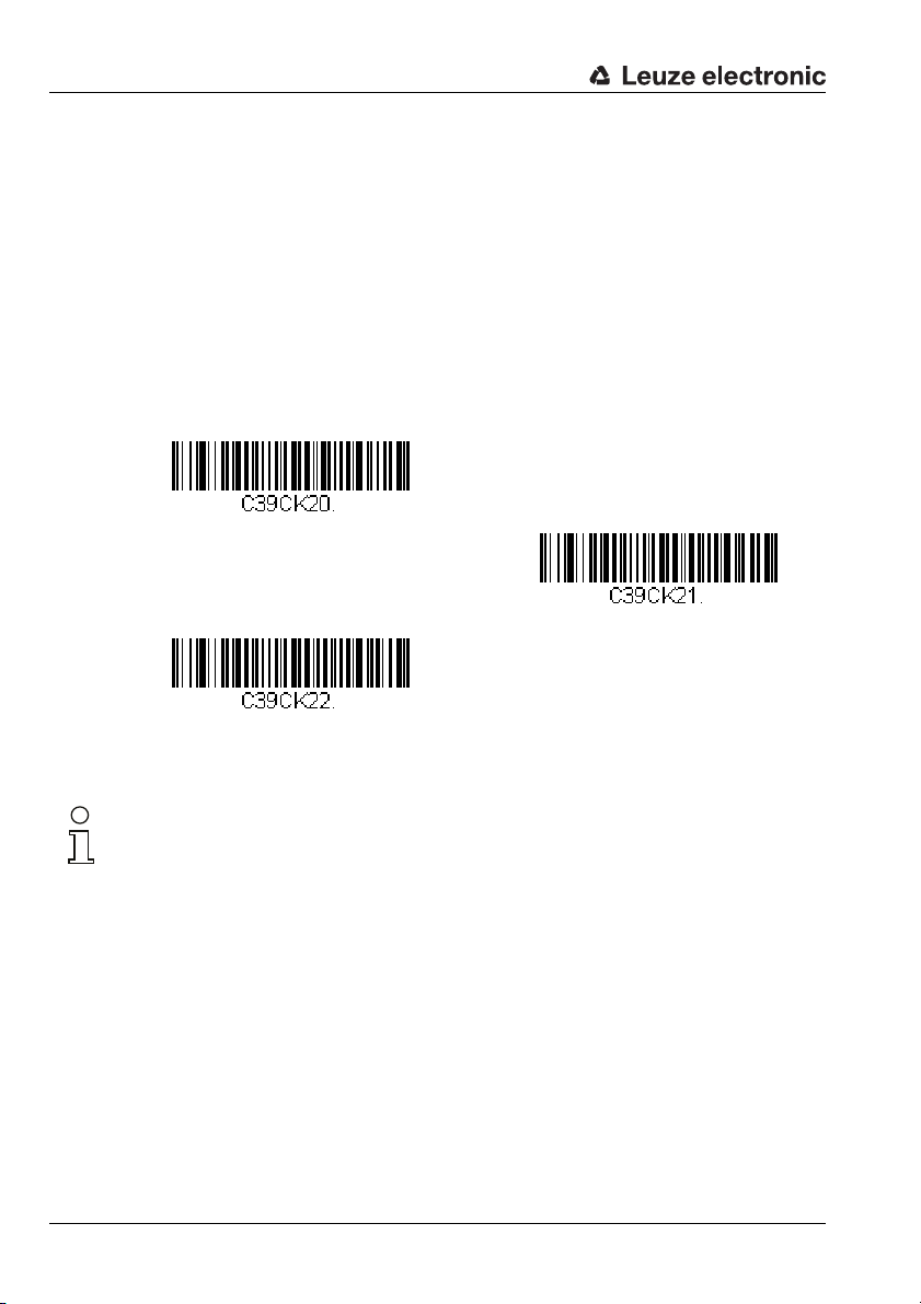
Configuration using configuration codes
Ignore check character
Evaluate check character but do not transmit
Evaluate and transmit check character
Handling of the Code 39 check character
For the handling of the optional check character present with Code 39, you can make the
following settings by reading in one of the following configuration codes:
• Ignore check character
Codes with and without check character are read (factory setting).
• Evaluate check character but do not transmit
Only codes with check character are read. The check character is validated.
• Evaluate and transmit check character
Only codes with check character are read. The check character is validated and output in the message string following the code content.
Figure 7.25: Configuration codes for handling the check character with Code 39
Notice!
For other code settings for the Code 39 code type, please contact Leuze electronic.
52 Technical description LSIS 22x Leuze electronic
Page 55
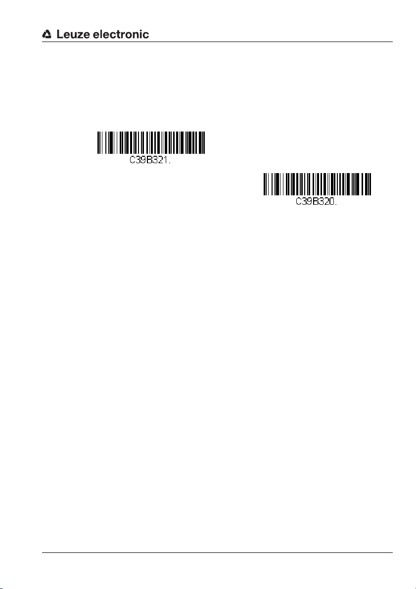
Configuration using configuration codes
Read code type Code 32 Pharmaceutical ON
Read code type Code 32 Pharmaceutical OFF
7.5.4 Code 32 Pharmaceutical code selection (PARAF)
By reading in one of the following configuration codes, reading of the Code 32 Pharmaceutical (PARAF) code type is activated or deactivated.
Figure 7.26: Configuration codes for activating/deactivating the Code 32 Pharmaceutical code type
Leuze electronic Technical description LSIS 22x 53
TNT 35/7-24V
Page 56
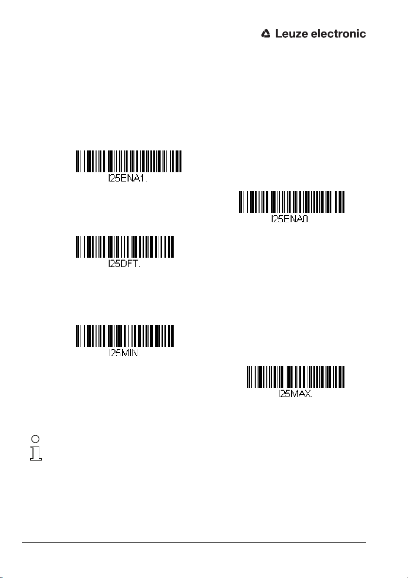
Configuration using configuration codes
Read code type Interleaved 2/5 ON
Read code type Interleaved 2/5 OFF
Interleaved 2/5 - standard settings
Interleaved 2/5 - minimum number of digits
Interleaved 2/5 - maximum number of digits
7.5.5 Interleaved 2/5 code selection
By reading one of the following configuration codes, reading of the Interleaved 2/5 code
type is activated or deactivated. In addition, it is possible to configure the number of digits
that are to be read (value range for number of digits: 2 … 80, factory setting: 4 … 80).
Also optionally configurable is the check-character evaluation and output.
Figure 7.27: Configuration codes for activating/deactivating the Interleaved 2/5 code type
Notice!
To set the minimum or maximum number of digits, please first read in the above configuration code and then the digits for the desired number of digits (see "Programming codes for
the configuration" on page 92). Conclude parameter entry by reading in the Save programming code.
54 Technical description LSIS 22x Leuze electronic
Page 57
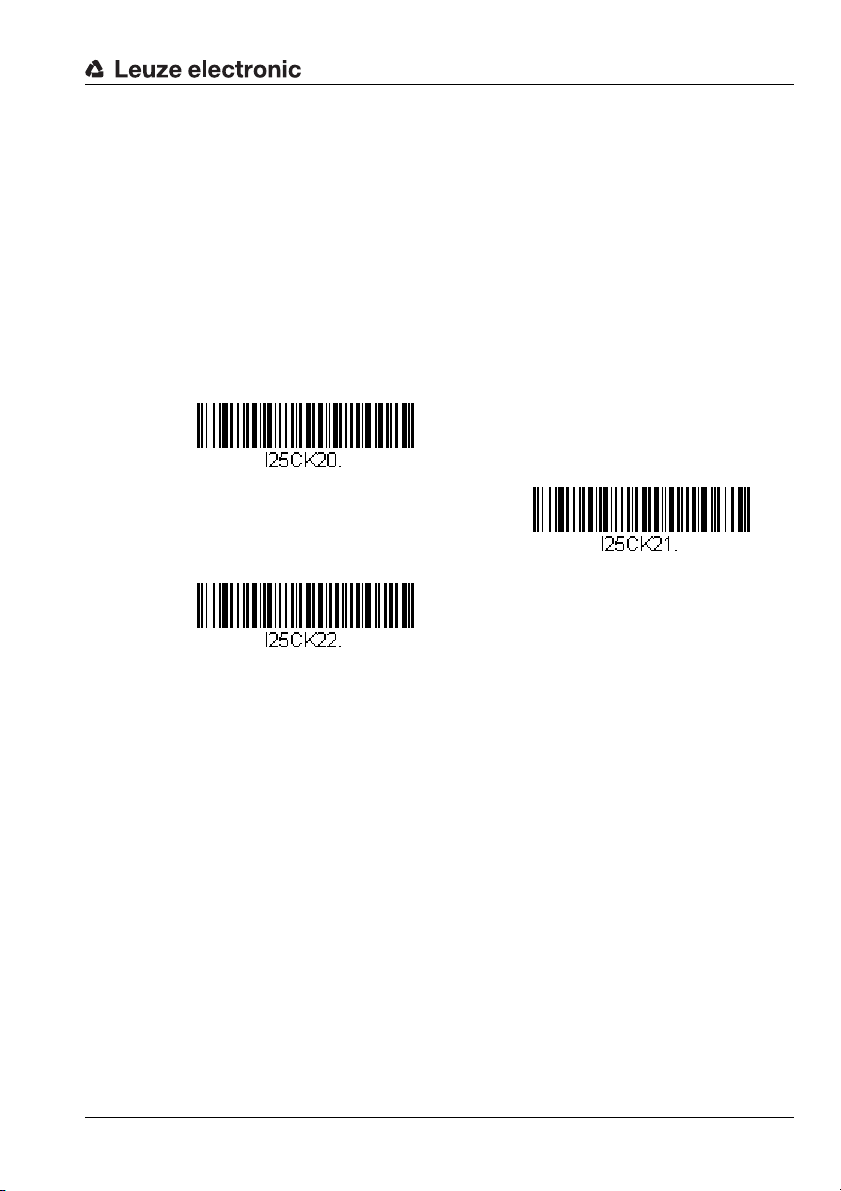
Configuration using configuration codes
Ignore check character
Evaluate check character but do not transmit
Evaluate and transmit check character
Handling of the Interleaved 2/5 check character
For the handling of the optional check character present with Code Interleaved 2/5, you can
make the following settings by reading in one of the following configuration codes:
• Ignore check character
Codes with and without check character are read (factory setting).
• Evaluate check character but do not transmit
Only codes with check character are read. The check character is validated.
• Evaluate and transmit check character
Only codes with check character are read. The check character is validated and output in the message string following the code content.
Figure 7.28: Configuration codes for handling the check character with Code Interleaved 2/5
Leuze electronic Technical description LSIS 22x 55
TNT 35/7-24V
Page 58

Configuration using configuration codes
Read code type Code 93 ON
Read code type Code 93 OFF
Code 93 - standard settings
Code 93 - minimum number of digits
Code 93 - maximum number of digits
7.5.6 Code 93 code selection
By reading in one of the following configuration codes, reading of the Code 93 code type
is activated or deactivated. In addition, it is possible to configure the number of digits that
are to be read (value range for number of digits: 0 … 80, factory setting: 0 … 80).
Figure 7.29: Configuration codes for activating/deactivating the Code 93 code type
Notice!
To set the minimum or maximum number of digits, please first read in the above configuration code and then the digits for the desired number of digits (see "Programming codes for
the configuration" on page 92). Conclude parameter entry by reading in the Save programming code.
Notice!
For other code settings for the Code 93 code type, please contact Leuze electronic.
56 Technical description LSIS 22x Leuze electronic
Page 59
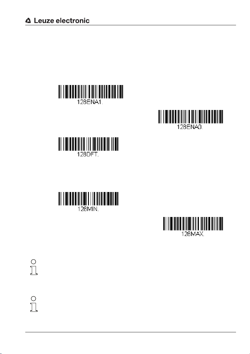
7.5.7 Code 128 code selection
Read code type Code 128 ON
Read code type Code 128 OFF
Code 128 - standard settings
Code 128 - minimum number of digits
Code 128 - maximum number of digits
By reading in one of the following configuration codes, reading of the Code 128 code type
is activated or deactivated. In addition, it is possible to configure the number of digits that
are to be read (value range for number of digits: 0 … 90, factory setting: 0 … 90).
Configuration using configuration codes
Figure 7.30: Configuration codes for activating/deactivating the Code 128 code type
Notice!
To set the minimum or maximum number of digits, please first read in the above configuration code and then the digits for the desired number of digits (see "Programming codes for
the configuration" on page 92). Conclude parameter entry by reading in the Save programming code.
Notice!
For other code settings for the Code 128 code type, please contact Leuze electronic.
Leuze electronic Technical description LSIS 22x 57
TNT 35/7-24V
Page 60

Configuration using configuration codes
Read code type GS1-128 ON
Read code type GS1-128 OFF
GS1-128 - standard settings
GS1-128 - minimum number of digits
GS1-128 - maximum number of digits
7.5.8 GS1-128 code selection
By reading in one of the following configuration codes, reading of the GS1-128 code type
is activated or deactivated. In addition, it is possible to configure the number of digits that
are to be read (value range for number of digits: 1 … 80, factory setting: 1 … 80).
Figure 7.31: Configuration codes for activating/deactivating the GS1-128 code type
Notice!
To set the minimum or maximum number of digits, please first read in the above configuration code and then the digits for the desired number of digits (see "Programming codes for
the configuration" on page 92). Conclude parameter entry by reading in the Save programming code.
58 Technical description LSIS 22x Leuze electronic
Page 61

7.5.9 UPC-A code selection
Read code type UPC-A ON
Read code type UPC-A OFF
UPC-A - standard settings
By reading in one of the following configuration codes, reading of the UPC-A code type is
activated or deactivated.
Figure 7.32: Configuration codes for activating/deactivating the UPC-A code type
Notice!
For further code settings for the UPC-A code type, please contact Leuze electronic.
Configuration using configuration codes
Leuze electronic Technical description LSIS 22x 59
TNT 35/7-24V
Page 62

Configuration using configuration codes
Read code type UPC-E0 ON
Read code type UPC-E0 OFF
UPC-E0 - standard settings
Read code type UPC-E1 ON
Read code type UPC-E1 OFF
7.5.10 UPC-E0 code selection
By reading in one of the following configuration codes, reading of the UPC-E0 code type
is activated or deactivated.
Figure 7.33: Configuration codes for activating/deactivating the UPC-E0 code type
Notice!
For further code settings for the UPC-E0 code type, please contact Leuze electronic.
7.5.11 UPC-E1 code selection
By reading in one of the following configuration codes, reading of the UPC-E1 code type
is activated or deactivated.
Figure 7.34: Configuration codes for activating/deactivating the UPC-E1 code type
60 Technical description LSIS 22x Leuze electronic
Page 63

7.5.12 EAN/JAN-13 code selection
Read code type EAN/JAN-13 ON
Read code type EAN/JAN-13 OFF
EAN/JAN-13 - standard settings
By reading in one of the following configuration codes, reading of the EAN/JAN-13 code
type is activated or deactivated.
Figure 7.35: Configuration codes for activating/deactivating the EAN/JAN-13 code type
Notice!
For other code settings for the EAN/JAN-13 code type, please contact Leuze electronic.
Configuration using configuration codes
Leuze electronic Technical description LSIS 22x 61
TNT 35/7-24V
Page 64
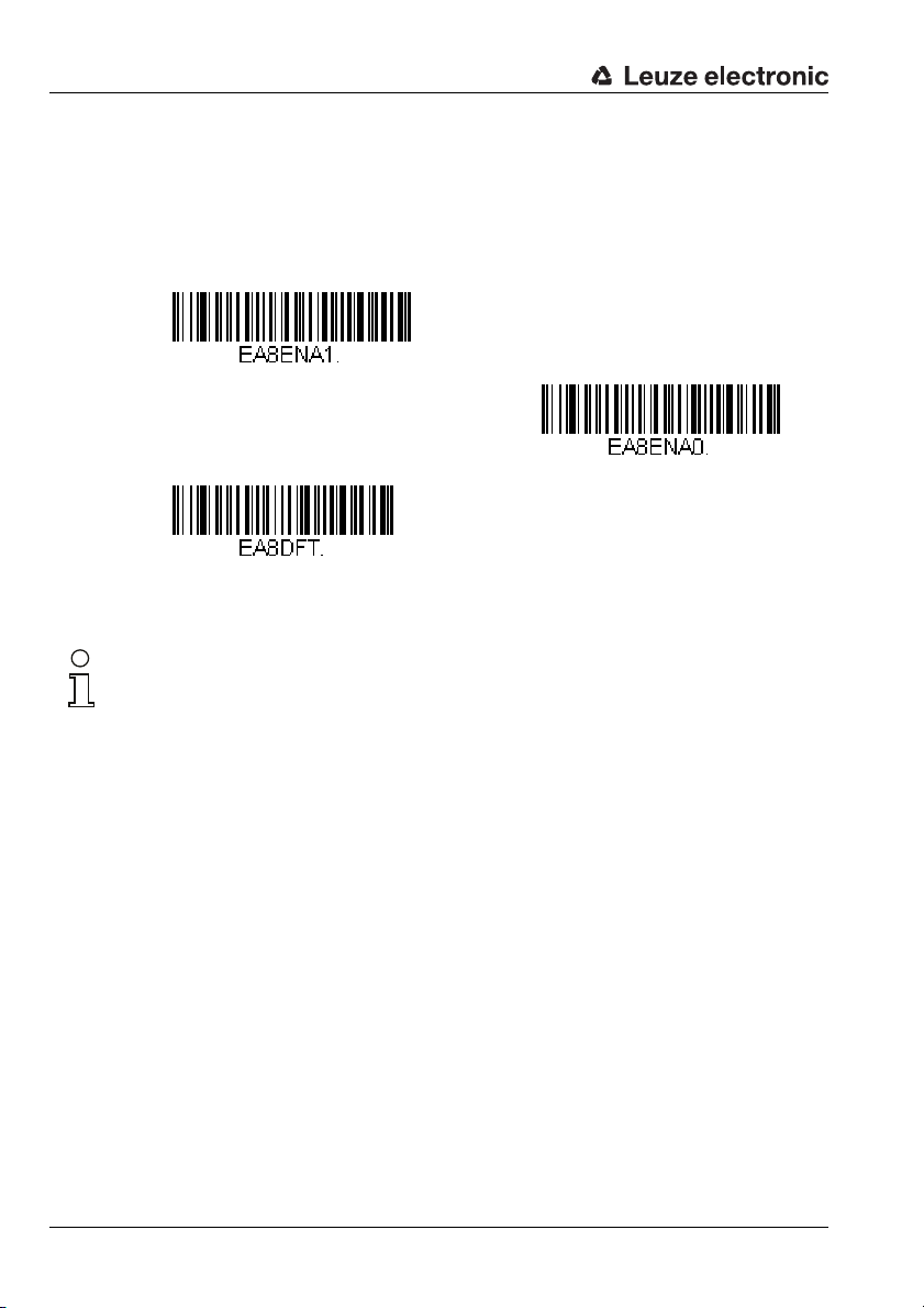
Configuration using configuration codes
Read code type EAN/JAN-8 ON
Read code type EAN/JAN-8 OFF
EAN/JAN-8 - standard settings
7.5.13 EAN/JAN-8 code selection
By reading in one of the following configuration codes, reading of the EAN/JAN-8 code
type is activated or deactivated.
Figure 7.36: Configuration codes for activating/deactivating the EAN/JAN-8 code type
Notice!
For other code settings for the EAN/JAN-8 code type, please contact Leuze electronic.
62 Technical description LSIS 22x Leuze electronic
Page 65
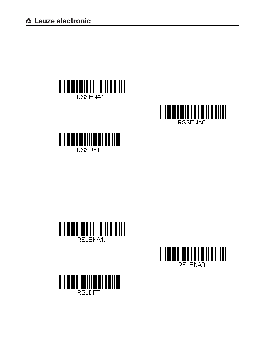
Configuration using configuration codes
Read code type GS1 DataBar Omnidirectional ON
Read code type GS1 DataBar Omnidirectional OFF
GS1 DataBar Omnidirectional -
standard settings
Read code type GS1 DataBar Limited ON
Read code type GS1 DataBar Limited OFF
GS1 DataBar Limited -
standard settings
7.5.14 GS1 DataBar Omnidirectional code selection
By reading in one of the following configuration codes, reading of the GS1 DataBar
Omnidirectional code type is activated or deactivated.
Figure 7.37: Configuration codes for activating/deactivating the GS1 DataBar Omnidirectional code type
7.5.15 GS1 DataBar Limited code selection
By reading in one of the following configuration codes, reading of the GS1 DataBar
Limited code type is activated or deactivated.
Figure 7.38: Configuration codes for activating/deactivating the GS1 DataBar Limited code type
Leuze electronic Technical description LSIS 22x 63
TNT 35/7-24V
Page 66

Configuration using configuration codes
Read code type GS1 DataBar Expanded ON
Read code type GS1 DataBar Expanded OFF
GS1 DataBar Expanded -
standard settings
GS1 DataBar Expanded -
minimum number of digits
GS1 DataBar Expanded -
maximum number of digits
7.5.16 GS1 DataBar Expanded code selection
By reading in one of the following configuration codes, reading of the GS1 DataBar
Expanded code type is activated or deactivated. In addition, it is possible to configure the
number of digits that are to be read (value range for number of digits: 4 … 74, factory
setting: 4 … 74).
Figure 7.39: Configuration codes for activating/deactivating the GS1 DataBar Expanded code type
Notice!
To set the minimum or maximum number of digits, please first read in the above configuration code and then the digits for the desired number of digits (see "Programming codes for
the configuration" on page 92). Conclude parameter entry by reading in the Save programming code.
64 Technical description LSIS 22x Leuze electronic
Page 67
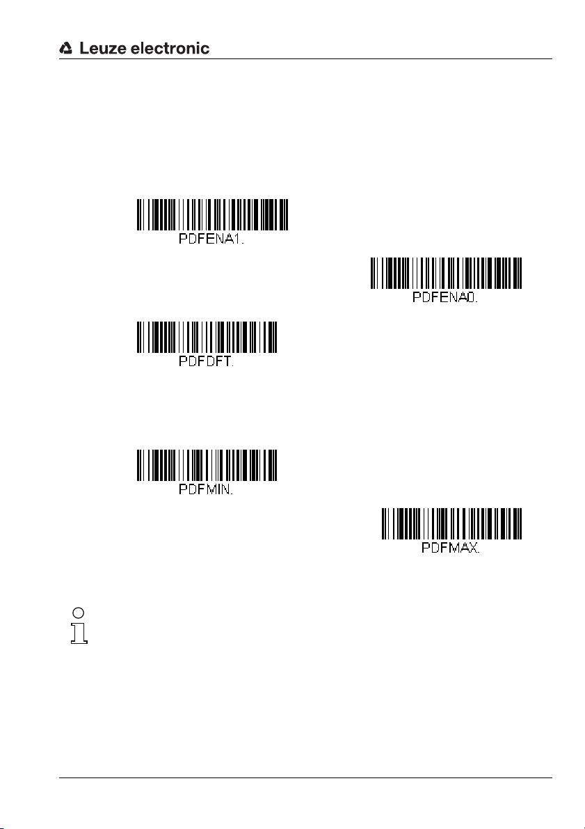
7.5.17 PDF417 code selection
Read code type PDF417 ON
Read code type PDF417 OFF
PDF417 - standard settings
PDF417 - minimum number of digits
PDF417 - maximum number of digits
By reading in one of the following configuration codes, reading of the PDF417 code type is
activated or deactivated. In addition, it is possible to configure the number of digits that are
to be read (value range for number of digits: 1 … 2750, factory setting: 1 … 2750).
Configuration using configuration codes
Figure 7.40: Configuration codes for activating/deactivating the PDF417 code type
Notice!
To set the minimum or maximum number of digits, please first read in the above configuration code and then the digits for the desired number of digits (see "Programming codes for
the configuration" on page 92). Conclude parameter entry by reading in the Save programming code.
Leuze electronic Technical description LSIS 22x 65
TNT 35/7-24V
Page 68
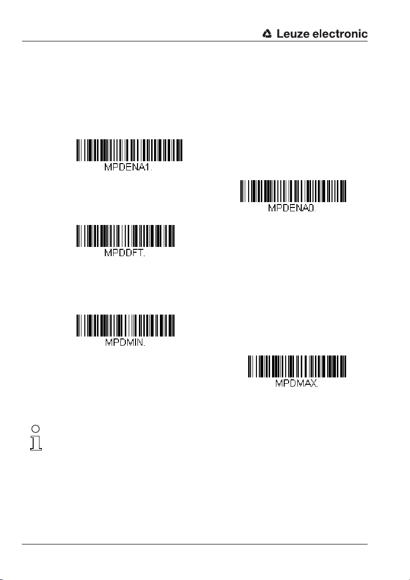
Configuration using configuration codes
Read code type MicroPDF417 ON
Read code type MicroPDF417 OFF
MicroPDF417 - standard settings
MicroPDF417 - minimum number of digits
MicroPDF417 - maximum number of digits
7.5.18 MicroPDF417 code selection
By reading in one of the following configuration codes, reading of the MicroPDF417 code
type is activated or deactivated. In addition, it is possible to configure the number of digits
that are to be read (value range for number of digits: 1 … 366, factory setting: 1 … 366).
Figure 7.41: Configuration codes for activating/deactivating the MicroPDF417 code type
Notice!
To set the minimum or maximum number of digits, please first read in the above configuration code and then the digits for the desired number of digits (see "Programming codes for
the configuration" on page 92). Conclude parameter entry by reading in the Save programming code.
66 Technical description LSIS 22x Leuze electronic
Page 69
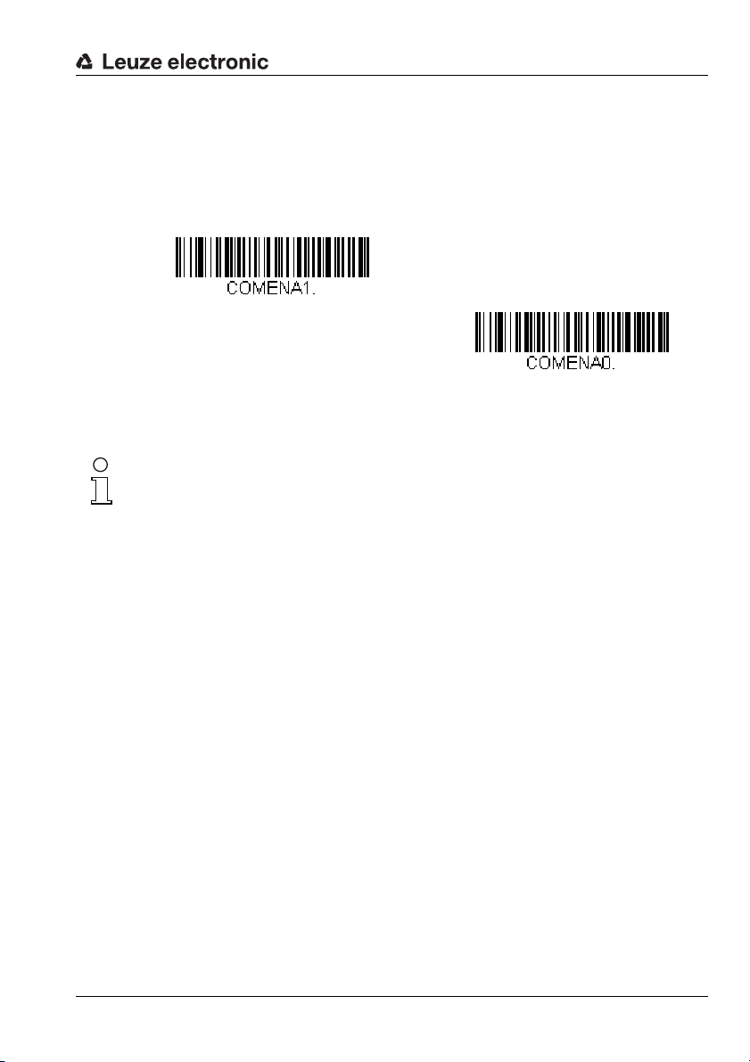
7.5.19 GS1 Composite code selection
Read code type GS1 Composite ON
Read code type GS1 Composite OFF
By reading in one of the following configuration codes, reading of the GS1 Composite
code type is activated or deactivated.
Figure 7.42: Configuration codes for activating/deactivating the GS1 Composite code type
Notice!
For further code settings for the
GS1 Composite
Configuration using configuration codes
code type, please contact Leuze electronic.
Leuze electronic Technical description LSIS 22x 67
TNT 35/7-24V
Page 70
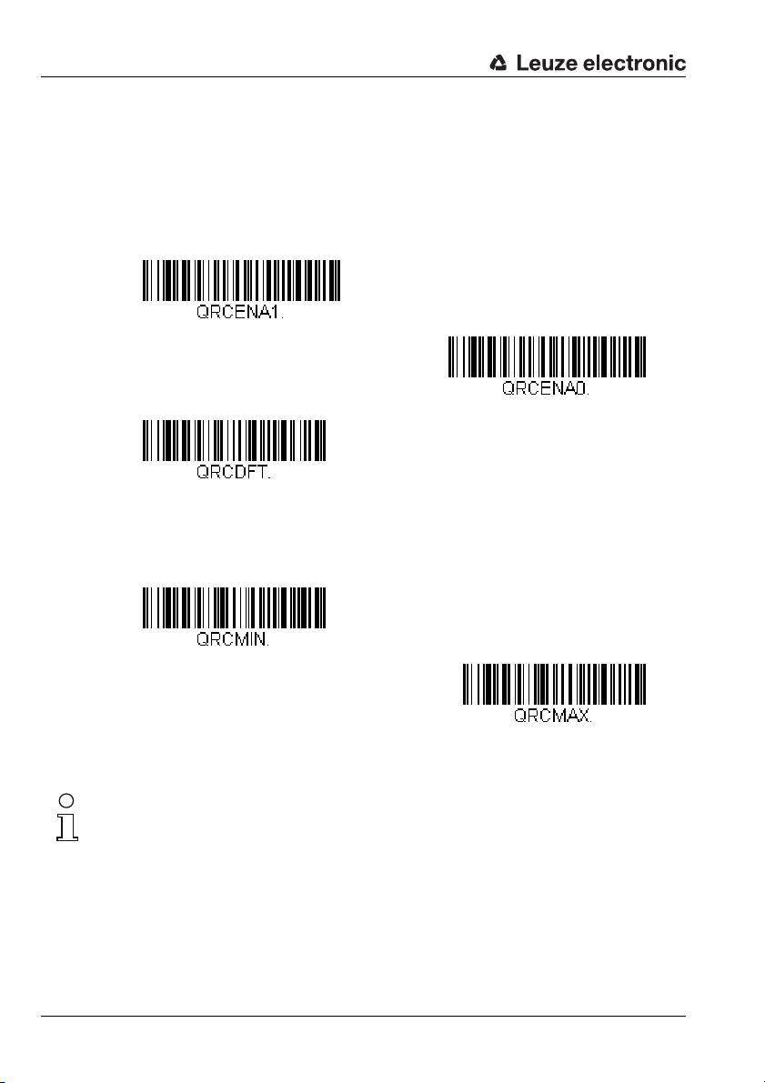
Configuration using configuration codes
Read code type QR Code ON
Read code type QR Code OFF
QR Code - standard settings
QR Code - minimum number of digits
QR Code - maximum number of digits
7.5.20 QR Code code selection
By reading in one of the following configuration codes, reading of the QR Code code type
is activated or deactivated. In addition, it is possible to configure the number of digits that
are to be read (value range for number of digits: 1 … 7089, factory setting: 1 … 7089).
Figure 7.43: Configuration codes for activating/deactivating the QR Code code type
Notice!
To set the minimum or maximum number of digits, please first read in the above configuration code and then the digits for the desired number of digits (see "Programming codes for
the configuration" on page 92). Conclude parameter entry by reading in the Save programming code.
68 Technical description LSIS 22x Leuze electronic
Page 71
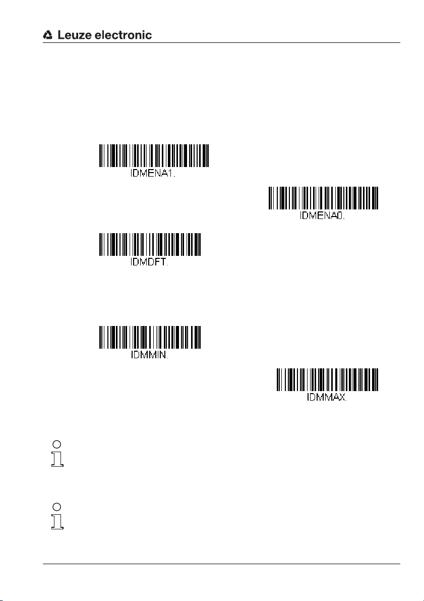
7.5.21 Data Matrix code selection
Read code type Data Matrix ON
Read code type Data Matrix OFF
Data Matrix - standard settings
Data Matrix - minimum number of digits
Data Matrix - maximum number of digits
By reading in one of the following configuration codes, reading of the Data Matrix code
type is activated or deactivated. In addition, it is possible to configure the number of digits
that are to be read (value range for number of digits: 1 … 3116, factory setting: 1 … 3116).
Configuration using configuration codes
Figure 7.44: Configuration codes for activating/deactivating the Data Matrix code type
Notice!
To set the minimum or maximum number of digits, please first read in the above configuration code and then the digits for the desired number of digits (see "Programming codes for
the configuration" on page 92). Conclude parameter entry by reading in the Save programming code.
Notice!
For further code settings for the Data Matrix code type, please contact Leuze electronic.
Leuze electronic Technical description LSIS 22x 69
TNT 35/7-24V
Page 72
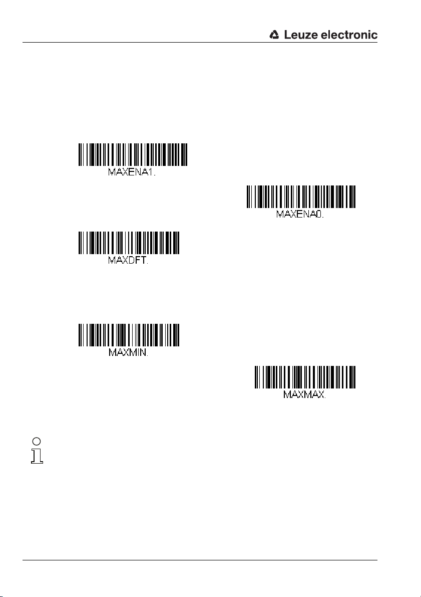
Configuration using configuration codes
Read code type MaxiCode ON
Read code type MaxiCode OFF
MaxiCode - standard settings
MaxiCode - minimum number of digits
MaxiCode - maximum number of digits
7.5.22 MaxiCode code selection
By reading in one of the following configuration codes, reading of the MaxiCode code type
is activated or deactivated. In addition, it is possible to configure the number of digits that
are to be read (value range for number of digits: 1 … 150, factory setting: 1 … 150).
Figure 7.45: Configuration codes for activating/deactivating the MaxiCode code type
Notice!
To set the minimum or maximum number of digits, please first read in the above configuration code and then the digits for the desired number of digits (see "Programming codes for
the configuration" on page 92). Conclude parameter entry by reading in the Save programming code.
70 Technical description LSIS 22x Leuze electronic
Page 73

7.5.23 Aztec Code code selection
Read code type Aztec Code ON
Read code type Aztec Code OFF
Aztec Code - standard settings
Aztec Code - minimum number of digits
Aztec Code - maximum number of digits
By reading in one of the following configuration codes, reading of the Aztec Code code
type is activated or deactivated. In addition, it is possible to configure the number of digits
that are to be read (value range for number of digits: 1 … 3832, factory setting: 1 … 3832).
Configuration using configuration codes
Figure 7.46: Configuration codes for activating/deactivating the Aztec Code code type
Notice!
To set the minimum or maximum number of digits, please first read in the above configuration code and then the digits for the desired number of digits (see "Programming codes for
the configuration" on page 92). Conclude parameter entry by reading in the Save programming code.
Notice!
For other code settings for the Aztec Code code type, please contact Leuze electronic.
Leuze electronic Technical description LSIS 22x 71
TNT 35/7-24V
Page 74

Configuration using configuration codes
Code ID temporary as prefix
7.6 Service codes
7.6.1 Code ID prefix
For test purposes, the code ID of the code type of the read code can be transmitted in the
message string as a prefix. The existing prefixes are then temporarily deleted and replaced
by the code ID as prefix. By reading in the following service code, this function is temporarily activated until the next power-OFF-ON.
Figure 7.47: Service code for temporarily transmitting the code ID as prefix
Listed in the following table are the code IDs of all code types supported by the LSIS 22x.
Code type Code ID - ASCII Code ID - hex
all code types 0x99
Australian Post A 0x41
Aztec Code z 0x7A
British Post B 0x42
Canadian Post C 0x43
China Post Q 0x51
Chinese Sensible Code (Han Xin Code) H 0x48
Codabar a 0x61
Codablock A V 0x56
Codablock F q 0x71
Code 11 h 0x68
Code 128 j 0x6A
GS1-128 I 0x49
Code 32 Pharmaceutical (PARAF) < 0x3C
Code 39 (supports Full ASCII mode) b 0x62
Code 49 l 0x6C
Code 93 and 93i i 0x69
Data Matrix w 0x77
EAN-13 (including Bookland EAN) d 0x64
EAN-13 with Add-On d 0x64
EAN-13 with Extended Coupon Code d 0x64
EAN-8 D 0x44
EAN-8 with Add-On D 0x44
Table 7.1: Code IDs of the code types for the LSIS 22x
72 Technical description LSIS 22x Leuze electronic
Page 75

Configuration using configuration codes
GS1 Composite y 0x79
GS1 DataBar y 0x79
InfoMail , 0x2C
Intelligent Mail Barcode M 0x4D
Interleaved 2 of 5 e 0x65
Japanese Post J 0x4A
KIX (Netherlands) Post K 0x4B
Korea Post ? 0x3F
Matrix 2 of 5 m 0x6D
MaxiCode x 0x78
MicroPDF417 R 0x52
MSI g 0x67
NEC 2 of 5 Y 0x59
OCR MICR (E 13 B) O 0x4F
OCR SEMI Font O 0x4F
OCR-A O 0x4F
OCR-B O 0x4F
PDF417 r 0x72
Planet Code L 0x4C
Postal-4i N 0x4E
Postnet P 0x50
QR Code and Micro QR Code s 0x73
Straight 2 of 5 IATA f 0x66
Straight 2 of 5 Industrial f 0x66
TCIF Linked Code 39 (TLC39) T 0x54
Telepen T 0x54
UPC-A c 0x63
UPC-A with Add-On c 0x63
UPC-A with Extended Coupon Code c 0x63
UPC-E E 0x45
UPC-E with Add-On E 0x45
UPC-E1 E 0x45
Table 7.1: Code IDs of the code types for the LSIS 22x
TNT 35/7-24V
Leuze electronic Technical description LSIS 22x 73
Page 76

Configuration using configuration codes
Revision number of the decoder hardware
Revision number of the decoder software
7.6.2 Decoder revision
By reading in the following service code, the revision number of the decoder hardware is
output.
Figure 7.48: Service code for outputting the revision number of the decoder hardware
7.6.3 Software revision
By reading in the following service code, the revision number of the decoder software is
output.
Figure 7.49: Service code for outputting the revision number of the decoder software
74 Technical description LSIS 22x Leuze electronic
Page 77

7.6.4 Reset to factory settings
Reset to factory settings
By reading in the following service code, the LSIS 22x is reset to factory settings.
Attention!
When resetting to factory settings, the entire configuration of the LSIS 22x is lost and
all parameters are reset to their standard values.
Figure 7.50: Service code for resetting to factory settings
Listed in the following are the most important factory settings according to device model:
Factory settings LSIS 222 M5M-R1 - RS 232 interface
•Baud rate 9600bit/s
• Data format 8 data bits, no parity, 1 stop bit
•Framing <STX>DATA<CR><LF>
• No read character ’?’
• Manual trigger mode start command: <SYN>T<CR>
Configuration using configuration codes
stop command: <SYN>U<CR>
Factory settings LSIS 223 M5M-R1 - USB interface
•USB operating mode USB keyboard emulation
• Keyboard layout GERMAN
•Framing ’ENTER’
• No read character none
•Streaming presentation mode
Leuze electronic Technical description LSIS 22x 75
TNT 35/7-24V
Page 78

Configuration using online commands
8 Configuration using online commands
Configuration can be performed via the RS 232 interface or via the USB interface with COM
port emulation with online commands.
Examples for online commands
Example 1:
To, e.g., configure a <STX> as prefix, the following command string must be sent:
<SYN>M<CR>PREBK29902.
The response from the LSIS 22x is:
PREBK29902<ACK>.
If an <ENQ> is sent as response, the command syntax was incorrect.
If an <NAK> is sent, the command could not be executed because the permissible value/
range was exceeded.
Notice!
If no response is received to the sent command, the interface is probably not correctly set.
Example 2:
To deactivate Code 128 as a readable code, the following command string must be sent:
<SYN>M<CR>128ENA0.
The response from the LSIS 22x is:
128ENA0<ACK>.
Notice!
The commands correspond to the content of the configuration codes that are printed in this
technical description. For further information on the topic of online commands, please contact Leuze electronic.
# Technical description LSIS 22x Leuze electronic
Page 79

9 Diagnostics and troubleshooting
9.1 State signaling via LED
Error Possible error causes Measures
Status LED 'PWR'
Off
Green continuous light • No error
Status LED ’IO’
Off
Green 0.3s • Decoding successful
Orange 0.3s
Red continuous light • Trigger signal present
Illumination LED behind the lens cover
Off
On • Trigger is activated
Table 9.1: LED states
Notice!
Please use chapter 9 as a master copy should servicing be required.
Cross the items in the "Measures" column which you have already examined, fill out the following address field and fax the pages together with your service contract to the fax number
listed below.
•No supply voltage connected to the
device
•Hardware error
•No trigger signal present
• No decoding
• Trigger present and decoding was
successful
•No trigger signal
•No supply voltage
•No USB connection (LSIS 223… only)
Diagnostics and troubleshooting
Check supply voltage
Send device to customer service
None
Switching signal for trigger
No decoding result
None
None
None
Press button
Connect voltage
Establish USB connection and check
driver
Hold up code
Customer data (please complete)
Device type:
Software version :
Company:
Customer order number:
Contact person/ Department:
Phone (direct):
Fax:
Street / No:
ZIP code/City:
Country:
Leuze Service fax number:
+49 7021 573 - 199
Leuze electronic Technical description LSIS 22x 77
TNT 35/7-24V
Page 80

Type overview and accessories
10 Type overview and accessories
10.1 Type overview LSIS 22x
Type designation Connection Interface Part no.
LSIS 222 M5M-R1 M12 connector RS 232, 300 … 115,200 baud 50117536
LSIS 223 M5M-R1 M12 connector USB 2.0 50117534
Table 10.1: Type overview LSIS 22x
10.2 Mounting device accessories
Type designation Description Part no.
BT 8-0 Mounting block for dovetail 50036196
BTU 300M - D10 Through hole fastening for rod D = 10mm or cheek 1.5 … 4 mm 50117253
BTU 300M - D12 Through hole fastening for rod D = 12mm or cheek 1.5 … 4 mm 50117252
BTU 300M - D14 Through hole fastening for rod D = 14mm or cheek 1.5 … 4 mm 50117251
Table 10.2: Mounting devices for the LSIS 22x
10.3 Ready-made cable accessories
10.3.1 Connection cables
Order codes of the connection cables for LSIS 222 M5M-R1
Type designation Description Part no.
KB JST-M12A-8P-3000
KB M12A-8P-PC-IO-3000
KB 034-2000
3m connection cable, M12 socket axial, 8-pin, A-coded, shielded,
JST 10/6 system plug for connecting directly to MA 2 / MA 4… / MA 2xxi
3m connection cable, M12 socket axial, 8-pin, A-coded, shielded,
M12 connector axial, 4-pin + SUB-D9 socket
2m extension cable, M12 socket axial, 8-pin, A-coded, shielded,
M12 connector axial, 8-pin, A-coded
50111225
50111226
50037543
Table 10.3: Connection cables for LSIS 222 M5M-R1
Order codes of the connection cables for LSIS 223 M5M-R1
Type designation Description Part no.
KB M12A-8P-USB-3000
KB M12A-8P-USB-IO-3000
3m connection cable, M12 socket axial, 8-pin, A-coded, shielded,
type A USB connector
3m connection cable, M12 socket axial, 8-pin, A-coded, shielded,
M12 connector axial, 4-pin + type A USB connector
50111227
50111228
Table 10.4: Connection cables for LSIS 223 M5M-R1
78 Technical description LSIS 22x Leuze electronic
Page 81
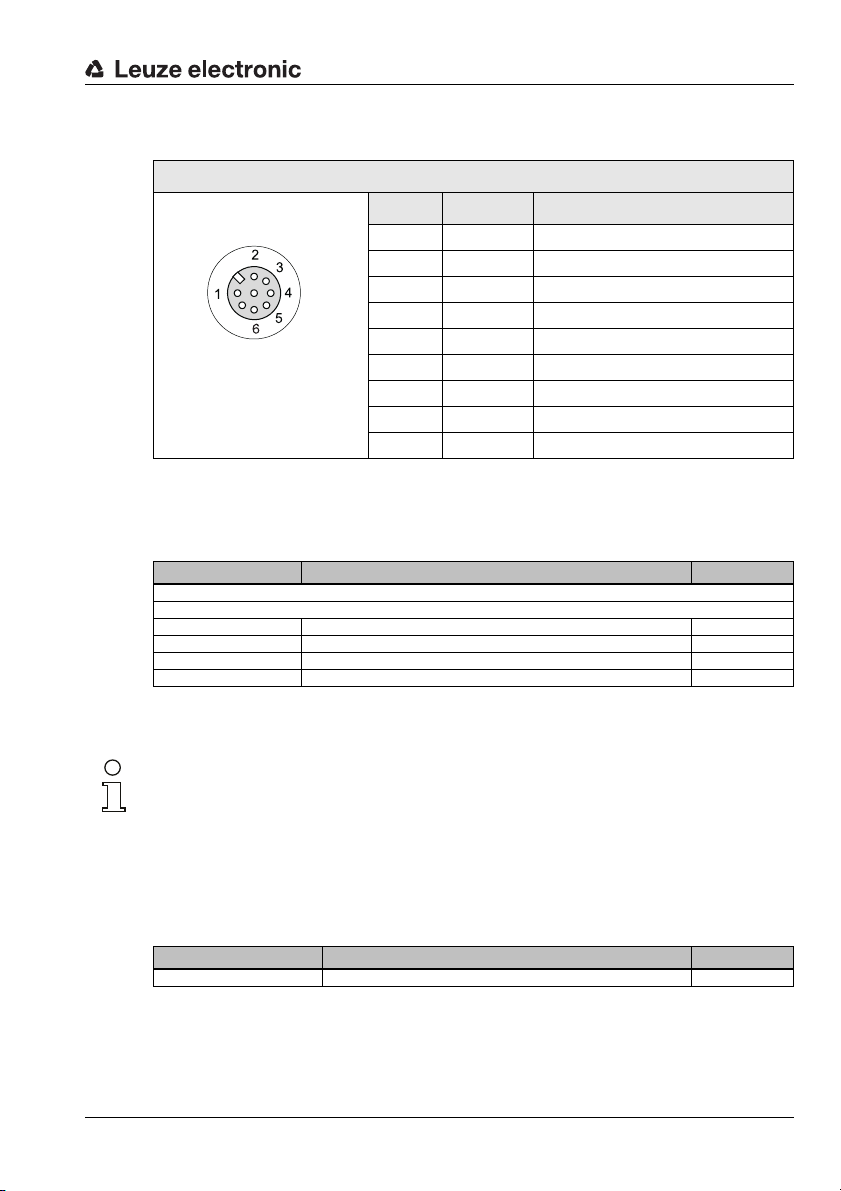
Type overview and accessories
SWI
SWO
n.c.
RXD / D+
TXD / D
-
VB
GNDFE
7
M12 socket
(A-coded)
10.3.2 Connection cables (8-pin, socket - open cable ends)
Connection cable (8-pin socket, A-coded)
Pin Name Core color
1Vin / VB brown
2SWI white
3 GNDIN / GND Blue
4SWO black
5n.c. gray
6 RXD / D+ pink
7 TXD / D- violet
8 FE orange
Thread FE bright
Table 10.5: Pin assignments KB M 12/8-…-BA
Order codes of the cables
Type designation Description Part no.
M12 socket, axial connector, open cable end
KB M12/8-1000-BA Cable length 1 m 50110170
KB M12/8-2000-BA Cable length 2 m 50110171
KB M12/8-5000-BA Cable length 5 m 50110172
KB M12/8-10000-BA Cable length 10 m 50110173
Table 10.6: Connection cable for the LSIS 22x
Notice!
Operation of the RS 232 host interface is only permissible with shielded cables with
maximum cable length of 10m.
Operation of the USB 2.0 host interface is only permissible with shielded cables with
maximum cable length of 3m.
10.3.3 Connector, user-configurable, not shielded
Type designation Description Part no.
KD 01-8-BA M12 connector, axial, socket, 8-pin, A-coded, terminals 50112157
Table 10.7: Connectors for the LSIS 22x
Leuze electronic Technical description LSIS 22x 79
TNT 35/7-24V
Page 82
Maintenance
11 Maintenance
11.1 General maintenance information
Usually, the code reader LSIS 22x does not require any maintenance by the operator.
Cleaning
Clean glass surface with a damp sponge soaked in commercial cleaning detergent. Then
rub it with a soft, clean, dry cloth.
Notice!
Do not use aggressive cleaning agents such as thinner or acetone for cleaning the device.
Use of improper cleaning agents can damage the housing window.
11.2 Repairs, servicing
Repairs to the device must only be carried out by the manufacturer.
Contact your Leuze distributor or service organization should repairs be required.
The addresses can be found on the inside of the cover and on the back.
Notice!
When sending devices to Leuze electronic for repair, please provide an accurate description
of the error.
11.3 Disassembling, packing, disposing
Repacking
For later reuse, the device is to be packed so that it is protected.
Notice!
Electrical scrap is a special waste product! Observe the locally applicable regulations
regarding disposal of the product.
80 Technical description LSIS 22x Leuze electronic
Page 83
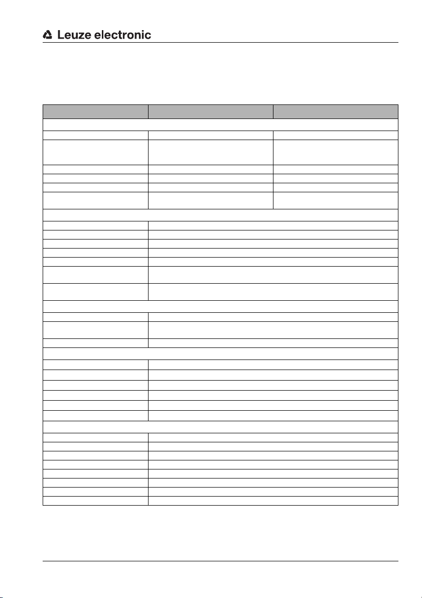
12 Specifications
12.1 General specifications of the code readers
Specifications
Typ e
Electrical data
Operating voltage
Current consumption
(recommended power
supply unit)
Process interface RS 232 USB
Transmission rate 300 … 115,200 bit/s USB 2.0
Switching input SWI (pin 2): 10VDC SWI (pin 2): 5V DC
Switching output SWO (pin 4): 10 … 30V DC
Optical data
Image sensor global shutter CMOS
Number of pixels 844 x 640
Integrated LED illumination red (approx. 624nm)
Integrated target LED (aimer) green (approx. 528 nm)
Code types all common 1D- and 2D-codes
Resolution 1D-codes: m = 0.127mm (5mil)
Object distance 1D-codes: 50 … 400mm (code-dependent, see reading distances)
Operating and display elements
PWR LED green operational readiness
Two-color I/O LED green 80ms: reading successful
Button manual trigger
Mechanical data
Housing
Lens cover
Protection class
VDE safety class
Weight
Dimensions (Hx W x D)
Environmental data
Operating temperature range 0°C … +40 °C
Storage temperature range -20°C … +70 °C
Air humidity max. 90% rel. humidity, non-condensing
LED illumination free group (no photobiological danger) acc. to EN 62471:2008
Vibration IEC 60068-2-6, test FC
Shock IEC 60068-2-27, test Ea
Electromagnetic compatibility EN 61000-6-2, EN 61000-6-3
Conformity CE, FCC Class B, UL
1)
LSIS 222 M5M-R1 LSIS 223 M5M-R1
10 … 30VDC (PELV, Class II) 4.75 … 5.25 VDC (PELV, Class II)
< 300mA (3 W) < 500mA (2.5 W)
max. = 20mA (short-circuit proof)
2D-codes: m = 0.169mm (6.67 mil)
2D-code: 50 … 200mm (code-dependent, see reading distances)
red: reading gate active
diecast zinc
Glass
IP 65 (with M12-connector screwed on)
III
130g
32 x 40 x 65.5mm
SWO (pin 4): 5VDC
max. = 20mA (short-circuit proof)
Table 12.1: Specifications of the LSIS 22x M5M-R1 code reader
1) Protective Extra Low Voltage (PELV) - protective extra-low voltage with reliable disconnection.
For UL Applications: for use in class 2 circuits according to NEC only!
TNT 35/7-24V
Leuze electronic Technical description LSIS 22x 81
Page 84

Specifications
A I/O indicator diode
B Control button (trigger)
C PWR indicator diode
D Optical axis
E Turning connector, turnable by 90°
F Thread depth 3.5 mm
12.2 Dimensioned drawing
Figure 12.1: Dimensioned drawing code reader LSIS 22x
82 Technical description LSIS 22x Leuze electronic
Page 85
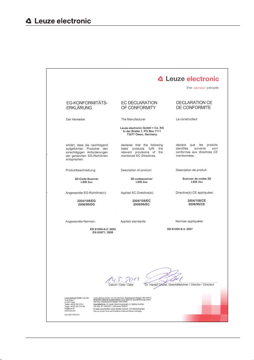
13 Appendix
13.1 Declaration of conformity
Appendix
Leuze electronic Technical description LSIS 22x 83
TNT 35/7-24V
Page 86

Appendix
13.2 ASCII character set
ASCII
NUL 0 00 0 NULL Zero
SOH 1 01 1 START OF HEADING Start of heading
STX 2 02 2 START OF TEXT Start of text characters
ETX 3 03 3 END OF TEXT Last character of text
EOT 4 04 4 END OF TRANSMISS. End of transmission
ENQ 5 05 5 ENQUIRY Request for data trans.
ACK 6 06 6 ACKNOWLEDGE Positive acknowledgment
BEL 7 07 7 BELL Bell signal
BS 8 08 10 BACKSPACE Backspace
HT 9 09 11 HORIZ. TABULATOR Horizontal tabulator
LF 10 0A 12 LINE FEED Line feed
VT 11 0B 13 VERT. TABULATOR Vertical tabulator
FF 12 0C 14 FORM FEED Form feed
CR 13 0D 15 CARRIAGE RETURN Carriage return
SO 14 0E 16 SHIFT OUT Shift out
SI 15 0F 17 SHIFT IN Shift in
DLE 16 10 20 DATA LINK ESCAPE Data link escape
DC1 17 11 21 DEVICE CONTROL 1 Device control character 1
DC2 18 12 22 DEVICE CONTROL 2 Device control character 2
DC3 19 13 23 DEVICE CONTROL 3 Device control character 3
DC4 20 14 24 DEVICE CONTROL 4 Device control character 4
NAK 21 15 25 NEG. ACKNOWLEDGE Negative acknowledge
SYN 22 16 26 SYNCHRONOUS IDLE Synchronization
ETB 23 17 27 EOF TRANSM. BLOCK End of data transmission block
CAN 24 18 30 CANCEL Invalid
EM 25 19 31 END OF MEDIUM End of medium
SUB 26 1A 32 SUBSTITUTE Substitution
ESC 27 1B 33 ESCAPE Escape
FS 28 1C 34 FILE SEPARATOR File separator
GS 29 1D 35 GROUP SEPARATOR Group separator
RS 30 1E 36 RECORD SEPARATOR Record separator
US 31 1F 37 UNIT SEPARATOR Unit separator
SP 32 20 40 SPACE Space
! 33 21 41 EXCLAMATION POINT Exclamation point
Dec. Hex. Oct. Designation Meaning
84 Technical description LSIS 22x Leuze electronic
Page 87

Appendix
ASCII
" 34 22 42 QUOTATION MARK Quotation mark
# 35 23 43 NUMBER SIGN Number sign
$ 36 24 44 DOLLAR SIGN Dollar sign
% 372545 PERCENT SIGN Percent sign
& 382646 AMPERSAND Ampersand
’ 392747 APOSTROPHE Apostrophe
( 40 28 50 OPEN. PARENTHESIS Open parenthesis
) 41 29 51 CLOS. PARENTHESIS Closed parenthesis
* 42 2A 52 ASTERISK Asterisk
+ 43 2B 53 PLUS Plus sign
,442C54 COMMA Comma
- 45 2D 55 HYPHEN (MINUS) Hyphen
. 46 2E 56 PERIOD (DECIMAL) Period (decimal)
/ 47 2F 57 SLANT Slant
0 483060 0 Number
1 493161 1 Number
2 503262 2 Number
3 513363 3 Number
4 523464 4 Number
5 533565 5 Number
6 543666 6 Number
7 553767 7 Number
8 563870 8 Number
9 573971 9 Number
: 58 3A 72 COLON Colon
; 59 3B 73 SEMICOLON Semicolon
< 60 3C 74 LESS THAN Less than
= 61 3D 75 EQUALS Equals
> 62 3E 76 GREATER THAN Greater than
? 63 3F 77 QUESTION MARK Question mark
Dec. Hex. Oct. Designation Meaning
@ 64 40 100 COMMERCIAL AT Commercial AT
A 65 41 101 A Capital letter
B 66 42 102 B Capital letter
C 67 43 103 C Capital letter
D 68 44 104 D Capital letter
TNT 35/7-24V
Leuze electronic Technical description LSIS 22x 85
Page 88

Appendix
ASCII
Dec. Hex. Oct. Designation Meaning
E 69 45 105 E Capital letter
F 70 46 106 F Capital letter
G 71 47 107 G Capital letter
H 72 48 110 H Capital letter
I 73 49 111 I Capital letter
J 74 4A 112 J Capital letter
K 75 4B 113 K Capital letter
L 76 4C 114 L Capital letter
M 77 4D 115 M Capital letter
N 78 4E 116 N Capital letter
O 79 4F 117 O Capital letter
P 80 50 120 P Capital letter
Q 81 51 121 Q Capital letter
R 82 52 122 R Capital letter
S 83 53 123 S Capital letter
T 84 54 124 T Capital letter
U 85 55 125 U Capital letter
V 86 56 126 V Capital letter
W 87 57 127 W Capital letter
X 88 58 130 X Capital letter
Y 89 59 131 Y Capital letter
Z 90 5A 132 Z Capital letter
[ 91 5B 133 OPENING BRACKET Opening bracket
\ 92 5C 134 REVERSE SLANT Reverse slant
] 93 5D 135 CLOSING BRACKET Closing bracket
^ 94 5E 136 CIRCUMFLEX Circumflex
_ 95 5F 137 UNDERSCORE Underscore
‘ 96 60 140 GRAVE ACCENT Grave accent
a 97 61 141 a Lower case letter
b 98 62 142 b Lower case letter
c 99 63 143 c Lower case letter
d 100 64 144 d Lower case letter
e 101 65 145 e Lower case letter
f 102 66 146 f Lower case letter
g 103 67 147 g Lower case letter
86 Technical description LSIS 22x Leuze electronic
Page 89
Appendix
ASCII
Dec. Hex. Oct. Designation Meaning
h 104 68 150 h Lower case letter
i 105 69 151 i Lower case letter
j 106 6A 152 j Lower case letter
k 107 6B 153 k Lower case letter
l 108 6C 154 l Lower case letter
m 109 6D 155 m Lower case letter
n 110 6E 156 n Lower case letter
o 111 6F 157 o Lower case letter
p 112 70 160 p Lower case letter
q 113 71 161 q Lower case letter
r 114 72 162 r Lower case letter
s 115 73 163 s Lower case letter
t 116 74 164 t Lower case letter
u 117 75 165 u Lower case letter
v 118 76 166 v Lower case letter
w 119 77 167 w Lower case letter
x 120 78 170 x Lower case letter
y 121 79 171 y Lower case letter
z 122 7A 172 z Lower case letter
{ 123 7B 173 OPENING BRACE Opening brace
| 124 7C 174 VERTICAL LINE Vertical line
} 125 7D 175 CLOSING BRACE Closing brace
~ 126 7E 176 TILDE Tilde
DEL 127 7F 177 DELETE (RUBOUT) Delete
TNT 35/7-24V
Leuze electronic Technical description LSIS 22x 87
Page 90

Appendix
SC 2
SC 3
SC 0 S
Modul 0,3
Modul 0,3
Modul 0,3
Modul 0,3
Modul 0,3
1122334455
135AC
A121314A
abcde
leuze
23456278901
1
3456 7890
1
122334 455666
77889
Code type 01: Interleaved 2 of 5
Code type 02: Code 39
Code type 11: Codabar
Code 128
Code type 08: GS1-128
Code type 06: UPC-A
Code type 07: EAN 8
Code type 10: EAN 13 Add-on
13.3 Sample codes
13.3.1 Bar codes module 0.3
88 Technical description LSIS 22x Leuze electronic
Figure 13.1: Bar code sample (module 0.3)
Page 91
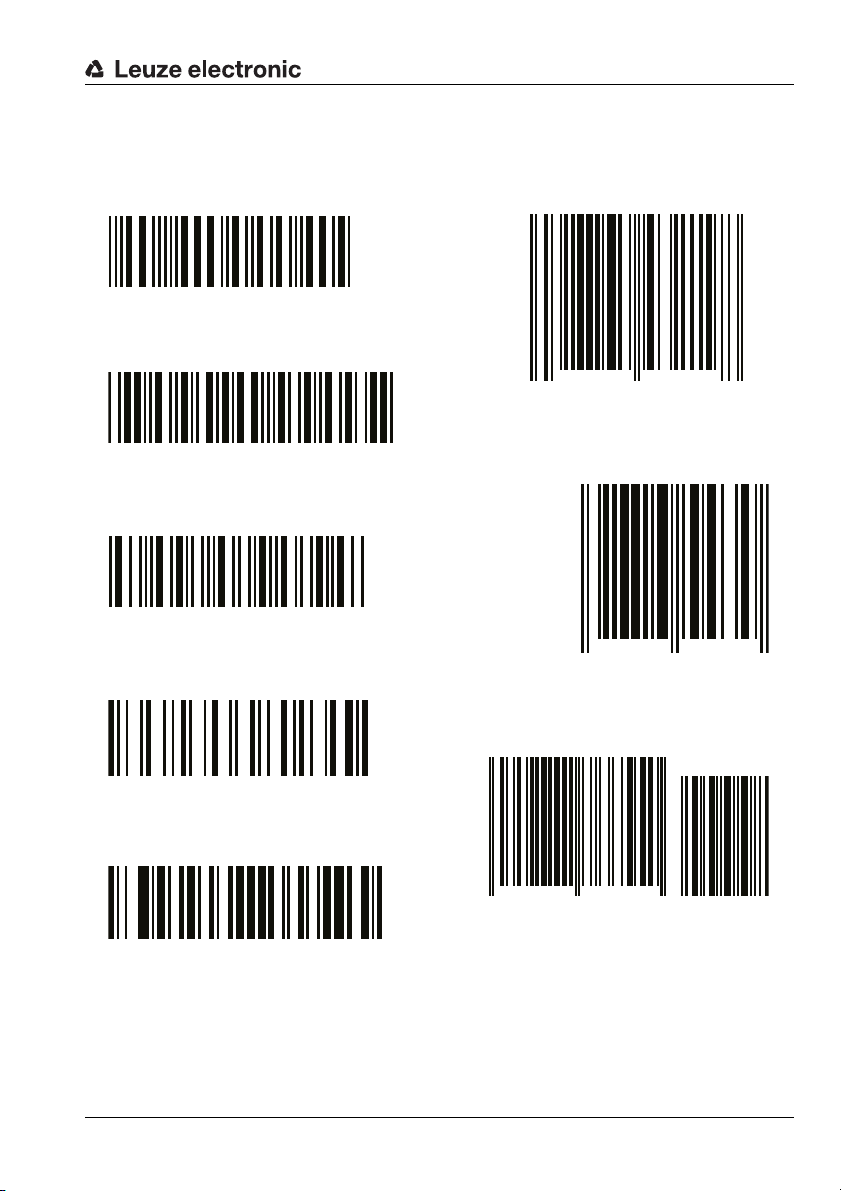
13.3.2 Bar codes module 0.5
Modul 0,5
6677889900
Modul 0,5
246BD
Modul 0,5
A151617A
Modul 0,5
fghij
Modul 0,5
LEUZE
SC 4
98765 43219
0 8
SC 6
9876 5430
SC 2
0
099887 766550
44332
Code type 01: Interleaved 2 of 5
Code type 02: Code 39
Code type 11: Codabar
Code 128
Code type 08: GS1-128
Code type 06: UPC-A
Code type 07: EAN 8
Code type 10: EAN 13 Add-on
Appendix
TNT 35/7-24V
Leuze electronic Technical description LSIS 22x 89
Figure 13.2: Bar code sample (module 0.5)
Page 92

Appendix
13.3.3 Other sample codes
Figure 13.3: Sample codes
90 Technical description LSIS 22x Leuze electronic
Page 93

Appendix
Figure 13.4: Sample codes
Leuze electronic Technical description LSIS 22x 91
TNT 35/7-24V
Page 94

Appendix
Digit ’0’
Digit ’1’
Digit ’2’
Digit ’3’
Digit ’4’
Digit ’5’
Digit ’6’
Digit ’7’
Digit ’8’
Digit ’9’
13.4 Programming codes for the configuration
Figure 13.5: Programming codes for configuration
92 Technical description LSIS 22x Leuze electronic
Page 95

Character ’A’
Character ’B’
Character ’C’
Character ’D’
Character ’E’
Character ’F’
SAVE
DISCARD
RESET
Appendix
Figure 13.6: Programming codes for configuration
Notice!
If you made an error while entering values, simply read in the DISCARD code and then again
read in the code for the value.
Conclude parameter entry by reading in the SAVE code.
Leuze electronic Technical description LSIS 22x 93
TNT 35/7-24V
 Loading...