

Leuze electronic CSL710-T05-1280.A-M12, CSL710-R05-1280.A/L-M12 Original Operating Instructions
Page 1

CSL 710
Switching light curtain
EN 2016/0750128684
We reserve the right to
make technical changes
Original operating instructions
Page 2

Leuze electronic GmbH + Co. KG
In der Braike 1
D-73277 Owen / Germany
Phone: +49 7021 573-0
Fax: +49 7021 573-199
http://www.leuze.com
info@leuze.de
Leuze electronic CSL 710 2
Page 3

1 About this document . . . . . . . . . . . . . . . . . . . . . . . . . . . . . . . . . . . . . . . . . . . . . . 6
1.1 Used symbols and signal words . . . . . . . . . . . . . . . . . . . . . . . . . . . . . . . . . . . . . . . . . . . . . 6
1.2 Terms and abbreviations . . . . . . . . . . . . . . . . . . . . . . . . . . . . . . . . . . . . . . . . . . . . . . . . . . . 6
2 Safety . . . . . . . . . . . . . . . . . . . . . . . . . . . . . . . . . . . . . . . . . . . . . . . . . . . . . . . . . . 8
2.1 Intended use . . . . . . . . . . . . . . . . . . . . . . . . . . . . . . . . . . . . . . . . . . . . . . . . . . . . . . . . . . . . 8
2.2 Foreseeable misuse . . . . . . . . . . . . . . . . . . . . . . . . . . . . . . . . . . . . . . . . . . . . . . . . . . . . . . 8
2.3 Competent persons . . . . . . . . . . . . . . . . . . . . . . . . . . . . . . . . . . . . . . . . . . . . . . . . . . . . . . . 8
2.4 Exemption of liability . . . . . . . . . . . . . . . . . . . . . . . . . . . . . . . . . . . . . . . . . . . . . . . . . . . . . . 9
3 Device description . . . . . . . . . . . . . . . . . . . . . . . . . . . . . . . . . . . . . . . . . . . . . . . 10
3.1 General information . . . . . . . . . . . . . . . . . . . . . . . . . . . . . . . . . . . . . . . . . . . . . . . . . . . . . . 10
3.2 General performance characteristics. . . . . . . . . . . . . . . . . . . . . . . . . . . . . . . . . . . . . . . . . 10
3.3 Connection technology . . . . . . . . . . . . . . . . . . . . . . . . . . . . . . . . . . . . . . . . . . . . . . . . . . . 11
3.4 Display elements . . . . . . . . . . . . . . . . . . . . . . . . . . . . . . . . . . . . . . . . . . . . . . . . . . . . . . . . 11
3.4.1 Operation indicators on the receiver control panel . . . . . . . . . . . . . . . . . . . . . . . . . . . . . . 11
3.4.2 Display on the receiver control panel . . . . . . . . . . . . . . . . . . . . . . . . . . . . . . . . . . . . . . . . 12
3.4.3 Operating indicators on the transmitter . . . . . . . . . . . . . . . . . . . . . . . . . . . . . . . . . . . . . . . 13
3.5 Operating elements on the receiver control panel. . . . . . . . . . . . . . . . . . . . . . . . . . . . . . . 13
3.6 Menu structure of the receiver control panel . . . . . . . . . . . . . . . . . . . . . . . . . . . . . . . . . . . 13
3.7 Menu navigation on the receiver control panel . . . . . . . . . . . . . . . . . . . . . . . . . . . . . . . . . 15
3.7.1 Meaning of the display icons . . . . . . . . . . . . . . . . . . . . . . . . . . . . . . . . . . . . . . . . . . . . . . . 15
3.7.2 Level display . . . . . . . . . . . . . . . . . . . . . . . . . . . . . . . . . . . . . . . . . . . . . . . . . . . . . . . . . . . 15
3.7.3 Menu navigation . . . . . . . . . . . . . . . . . . . . . . . . . . . . . . . . . . . . . . . . . . . . . . . . . . . . . . . . 16
3.7.4 Editing value parameters. . . . . . . . . . . . . . . . . . . . . . . . . . . . . . . . . . . . . . . . . . . . . . . . . . 16
3.7.5 Editing selection parameters . . . . . . . . . . . . . . . . . . . . . . . . . . . . . . . . . . . . . . . . . . . . . . . 17
4 Functions . . . . . . . . . . . . . . . . . . . . . . . . . . . . . . . . . . . . . . . . . . . . . . . . . . . . . . 19
4.1 Beam modes . . . . . . . . . . . . . . . . . . . . . . . . . . . . . . . . . . . . . . . . . . . . . . . . . . . . . . . . . . . 19
4.1.1 Parallel. . . . . . . . . . . . . . . . . . . . . . . . . . . . . . . . . . . . . . . . . . . . . . . . . . . . . . . . . . . . . . . . 19
4.1.2 Diagonal . . . . . . . . . . . . . . . . . . . . . . . . . . . . . . . . . . . . . . . . . . . . . . . . . . . . . . . . . . . . . . 19
4.1.3 Crossed-beam . . . . . . . . . . . . . . . . . . . . . . . . . . . . . . . . . . . . . . . . . . . . . . . . . . . . . . . . . . 20
4.2 Blanking. . . . . . . . . . . . . . . . . . . . . . . . . . . . . . . . . . . . . . . . . . . . . . . . . . . . . . . . . . . . . . . 21
4.3 Power-Up Teach . . . . . . . . . . . . . . . . . . . . . . . . . . . . . . . . . . . . . . . . . . . . . . . . . . . . . . . . 23
4.4 Smoothing . . . . . . . . . . . . . . . . . . . . . . . . . . . . . . . . . . . . . . . . . . . . . . . . . . . . . . . . . . . . . 23
4.5 External triggering . . . . . . . . . . . . . . . . . . . . . . . . . . . . . . . . . . . . . . . . . . . . . . . . . . . . . . . 24
4.6 Block evaluation of beam areas . . . . . . . . . . . . . . . . . . . . . . . . . . . . . . . . . . . . . . . . . . . . 25
4.6.1 Defining beam area . . . . . . . . . . . . . . . . . . . . . . . . . . . . . . . . . . . . . . . . . . . . . . . . . . . . . . 25
4.6.2 Autosplitting . . . . . . . . . . . . . . . . . . . . . . . . . . . . . . . . . . . . . . . . . . . . . . . . . . . . . . . . . . . . 25
4.6.3 Mapping beam area to switching output . . . . . . . . . . . . . . . . . . . . . . . . . . . . . . . . . . . . . . 25
4.6.4 Teach height area . . . . . . . . . . . . . . . . . . . . . . . . . . . . . . . . . . . . . . . . . . . . . . . . . . . . . . . 27
4.7 Switching outputs . . . . . . . . . . . . . . . . . . . . . . . . . . . . . . . . . . . . . . . . . . . . . . . . . . . . . . . 29
4.7.1 Light/dark switching . . . . . . . . . . . . . . . . . . . . . . . . . . . . . . . . . . . . . . . . . . . . . . . . . . . . . . 29
4.7.2 Time functions . . . . . . . . . . . . . . . . . . . . . . . . . . . . . . . . . . . . . . . . . . . . . . . . . . . . . . . . . . 29
4.8 Interference suppression (filter depth). . . . . . . . . . . . . . . . . . . . . . . . . . . . . . . . . . . . . . . . 29
5 Applications . . . . . . . . . . . . . . . . . . . . . . . . . . . . . . . . . . . . . . . . . . . . . . . . . . . . 31
5.1 Object counting . . . . . . . . . . . . . . . . . . . . . . . . . . . . . . . . . . . . . . . . . . . . . . . . . . . . . . . . . 31
5.2 Height monitoring and sorting of packets . . . . . . . . . . . . . . . . . . . . . . . . . . . . . . . . . . . . . 32
5.3 Hole recognition. . . . . . . . . . . . . . . . . . . . . . . . . . . . . . . . . . . . . . . . . . . . . . . . . . . . . . . . . 33
6 Mounting and installation . . . . . . . . . . . . . . . . . . . . . . . . . . . . . . . . . . . . . . . . . . 34
6.1 Mounting the light curtain . . . . . . . . . . . . . . . . . . . . . . . . . . . . . . . . . . . . . . . . . . . . . . . . . 34
Leuze electronic CSL 710 3
Page 4

6.2 Definition of directions of movement . . . . . . . . . . . . . . . . . . . . . . . . . . . . . . . . . . . . . . . . . 35
6.3 Fastening via sliding blocks. . . . . . . . . . . . . . . . . . . . . . . . . . . . . . . . . . . . . . . . . . . . . . . . 36
6.4 Fastening via swivel mount . . . . . . . . . . . . . . . . . . . . . . . . . . . . . . . . . . . . . . . . . . . . . . . . 36
6.5 Fastening via swiveling mounting brackets . . . . . . . . . . . . . . . . . . . . . . . . . . . . . . . . . . . . 37
7 Electrical connection . . . . . . . . . . . . . . . . . . . . . . . . . . . . . . . . . . . . . . . . . . . . . 38
7.1 Shielding and line lengths . . . . . . . . . . . . . . . . . . . . . . . . . . . . . . . . . . . . . . . . . . . . . . . . . 38
7.1.1 Shielding . . . . . . . . . . . . . . . . . . . . . . . . . . . . . . . . . . . . . . . . . . . . . . . . . . . . . . . . . . . . . . 38
7.1.2 Cable lengths for shielded cables . . . . . . . . . . . . . . . . . . . . . . . . . . . . . . . . . . . . . . . . . . . 40
7.2 Connection and interconnection cables. . . . . . . . . . . . . . . . . . . . . . . . . . . . . . . . . . . . . . . 40
7.3 Device connections . . . . . . . . . . . . . . . . . . . . . . . . . . . . . . . . . . . . . . . . . . . . . . . . . . . . . . 41
7.4 Digital inputs/outputs on connection X1 . . . . . . . . . . . . . . . . . . . . . . . . . . . . . . . . . . . . . . 41
7.5 Electrical connection – CSL 710 . . . . . . . . . . . . . . . . . . . . . . . . . . . . . . . . . . . . . . . . . . . . 41
7.5.1 X1 pin assignment – CSL 710 . . . . . . . . . . . . . . . . . . . . . . . . . . . . . . . . . . . . . . . . . . . . . . 42
7.5.2 X2/X3 pin assignment – CSL 710 . . . . . . . . . . . . . . . . . . . . . . . . . . . . . . . . . . . . . . . . . . . 43
7.6 Electrical supply. . . . . . . . . . . . . . . . . . . . . . . . . . . . . . . . . . . . . . . . . . . . . . . . . . . . . . . . . 43
8 Starting up the device - Basic configuration. . . . . . . . . . . . . . . . . . . . . . . . . . . . 44
8.1 Aligning transmitter and receiver . . . . . . . . . . . . . . . . . . . . . . . . . . . . . . . . . . . . . . . . . . . . 44
8.2 Teaching the environmental conditions . . . . . . . . . . . . . . . . . . . . . . . . . . . . . . . . . . . . . . . 46
8.2.1 Teach via receiver control panel . . . . . . . . . . . . . . . . . . . . . . . . . . . . . . . . . . . . . . . . . . . . 47
8.2.2 Teaching via a control signal from the control . . . . . . . . . . . . . . . . . . . . . . . . . . . . . . . . . . 48
8.3 Check alignment . . . . . . . . . . . . . . . . . . . . . . . . . . . . . . . . . . . . . . . . . . . . . . . . . . . . . . . . 49
8.4 Setting the function reserve. . . . . . . . . . . . . . . . . . . . . . . . . . . . . . . . . . . . . . . . . . . . . . . . 49
8.5 Extended configurations on the receiver control panel menu . . . . . . . . . . . . . . . . . . . . . . 50
8.5.1 Define digital inputs/outputs . . . . . . . . . . . . . . . . . . . . . . . . . . . . . . . . . . . . . . . . . . . . . . . 50
8.5.2 Inversion of the switching behavior (light/dark switching) . . . . . . . . . . . . . . . . . . . . . . . . . 52
8.5.3 Defining the filter depth . . . . . . . . . . . . . . . . . . . . . . . . . . . . . . . . . . . . . . . . . . . . . . . . . . . 52
8.5.4 Defining the display properties . . . . . . . . . . . . . . . . . . . . . . . . . . . . . . . . . . . . . . . . . . . . . 53
8.5.5 Changing the language . . . . . . . . . . . . . . . . . . . . . . . . . . . . . . . . . . . . . . . . . . . . . . . . . . . 53
8.5.6 Product information . . . . . . . . . . . . . . . . . . . . . . . . . . . . . . . . . . . . . . . . . . . . . . . . . . . . . . 54
8.5.7 Reset to factory settings . . . . . . . . . . . . . . . . . . . . . . . . . . . . . . . . . . . . . . . . . . . . . . . . . . 54
9 Starting up the CSL 710 with IO-Link interface . . . . . . . . . . . . . . . . . . . . . . . . . 55
9.1 Defining IO-Link configurations on the receiver control panel . . . . . . . . . . . . . . . . . . . . . . 55
9.2 Defining configurations via the IO-Link master module of the PLC-specific software . . . . 56
9.3 Parameter/process data for IO-Link . . . . . . . . . . . . . . . . . . . . . . . . . . . . . . . . . . . . . . . . . 56
10 Example configurations . . . . . . . . . . . . . . . . . . . . . . . . . . . . . . . . . . . . . . . . . . . 65
10.1 Example configuration - Mapping of beams 1 … 32 to output pin 2 . . . . . . . . . . . . . . . . . 65
10.1.1Configuration of area/output mapping (general) . . . . . . . . . . . . . . . . . . . . . . . . . . . . . . . . 65
10.2 Example configuration – Teach height area . . . . . . . . . . . . . . . . . . . . . . . . . . . . . . . . . . . 66
10.3 Example configuration - Activating and deactivating blanking areas. . . . . . . . . . . . . . . . . 67
10.3.1Configuration of blanking areas (general) . . . . . . . . . . . . . . . . . . . . . . . . . . . . . . . . . . . . . 67
10.4 Example configuration – smoothing. . . . . . . . . . . . . . . . . . . . . . . . . . . . . . . . . . . . . . . . . . 67
10.4.1Smoothing configuration (general) . . . . . . . . . . . . . . . . . . . . . . . . . . . . . . . . . . . . . . . . . . 67
11 Connecting to a PC –
11.1 System requirements. . . . . . . . . . . . . . . . . . . . . . . . . . . . . . . . . . . . . . . . . . . . . . . . . . . . . 68
11.2 Installing
11.2.1Installing the
11.2.2Installing drivers for IO-Link USB master . . . . . . . . . . . . . . . . . . . . . . . . . . . . . . . . . . . . . 69
11.2.3Connecting IO-Link USB master to the PC . . . . . . . . . . . . . . . . . . . . . . . . . . . . . . . . . . . . 70
11.2.4Connect the IO-Link USB master to the light curtain. . . . . . . . . . . . . . . . . . . . . . . . . . . . . 70
Sensor Studio
Sensor Studio
configuration software and IO-Link USB master. . . . . . . . . . . . . 69
Sensor Studio
. . . . . . . . . . . . . . . . . . . . . . . . . . . . . . . . . 68
FDT frame. . . . . . . . . . . . . . . . . . . . . . . . . . . . . . . . . . . . . . . 69
Leuze electronic CSL 710 4
Page 5

11.2.5Installing the DTM and IODD. . . . . . . . . . . . . . . . . . . . . . . . . . . . . . . . . . . . . . . . . . . . . . . 71
11.3 Starting the
11.4 Short description of the
11.4.1FDT frame menu . . . . . . . . . . . . . . . . . . . . . . . . . . . . . . . . . . . . . . . . . . . . . . . . . . . . . . . . 73
11.4.2
IDENTIFICATION
11.4.3
CONFIGURATION
11.4.4
PROCESS
11.4.5
DIAGNOSIS
Exiting Sensor Studio
11.4.6
Sensor Studio
function . . . . . . . . . . . . . . . . . . . . . . . . . . . . . . . . . . . . . . . . . . . . . . . . 73
function. . . . . . . . . . . . . . . . . . . . . . . . . . . . . . . . . . . . . . . . . . . . . . . . 73
function . . . . . . . . . . . . . . . . . . . . . . . . . . . . . . . . . . . . . . . . . . . . . . . . . . . . . . 74
function . . . . . . . . . . . . . . . . . . . . . . . . . . . . . . . . . . . . . . . . . . . . . . . . . . . . . 75
configuration software . . . . . . . . . . . . . . . . . . . . . . . . . . . . . . 71
Sensor Studio
. . . . . . . . . . . . . . . . . . . . . . . . . . . . . . . . . . . . . . . . . . . . . . . . . . . . 75
configuration software . . . . . . . . . . . . . . . . . . . . . 73
12 Troubleshooting . . . . . . . . . . . . . . . . . . . . . . . . . . . . . . . . . . . . . . . . . . . . . . . . . 76
12.1 What to do in case of failure? . . . . . . . . . . . . . . . . . . . . . . . . . . . . . . . . . . . . . . . . . . . . . . 76
12.2 Operating indicators of the LEDs. . . . . . . . . . . . . . . . . . . . . . . . . . . . . . . . . . . . . . . . . . . . 76
12.3 Error codes in the display . . . . . . . . . . . . . . . . . . . . . . . . . . . . . . . . . . . . . . . . . . . . . . . . . 77
13 Care, maintenance and disposal . . . . . . . . . . . . . . . . . . . . . . . . . . . . . . . . . . . . 80
13.1 Cleaning . . . . . . . . . . . . . . . . . . . . . . . . . . . . . . . . . . . . . . . . . . . . . . . . . . . . . . . . . . . . . . 80
13.2 Servicing . . . . . . . . . . . . . . . . . . . . . . . . . . . . . . . . . . . . . . . . . . . . . . . . . . . . . . . . . . . . . . 80
13.2.1Firmware update . . . . . . . . . . . . . . . . . . . . . . . . . . . . . . . . . . . . . . . . . . . . . . . . . . . . . . . . 80
13.3 Disposing. . . . . . . . . . . . . . . . . . . . . . . . . . . . . . . . . . . . . . . . . . . . . . . . . . . . . . . . . . . . . . 80
14 Service and support . . . . . . . . . . . . . . . . . . . . . . . . . . . . . . . . . . . . . . . . . . . . . . 81
15 Technical data . . . . . . . . . . . . . . . . . . . . . . . . . . . . . . . . . . . . . . . . . . . . . . . . . . 82
15.1 General specifications . . . . . . . . . . . . . . . . . . . . . . . . . . . . . . . . . . . . . . . . . . . . . . . . . . . . 82
15.2 Timing . . . . . . . . . . . . . . . . . . . . . . . . . . . . . . . . . . . . . . . . . . . . . . . . . . . . . . . . . . . . . . . . 85
15.3 Minimum object diameter for stationary objects . . . . . . . . . . . . . . . . . . . . . . . . . . . . . . . . 87
15.4 Dimensioned drawings . . . . . . . . . . . . . . . . . . . . . . . . . . . . . . . . . . . . . . . . . . . . . . . . . . . 88
15.5 Dimensioned drawings: Accessories. . . . . . . . . . . . . . . . . . . . . . . . . . . . . . . . . . . . . . . . . 89
16 Ordering information and accessories . . . . . . . . . . . . . . . . . . . . . . . . . . . . . . . . 92
16.1 Nomenclature . . . . . . . . . . . . . . . . . . . . . . . . . . . . . . . . . . . . . . . . . . . . . . . . . . . . . . . . . . 92
16.2 Accessories – CSL 710 . . . . . . . . . . . . . . . . . . . . . . . . . . . . . . . . . . . . . . . . . . . . . . . . . . . 93
16.2.1Connection to the switch cabinet (screw terminals) . . . . . . . . . . . . . . . . . . . . . . . . . . . . . 93
16.2.2Connection to IO-Link master . . . . . . . . . . . . . . . . . . . . . . . . . . . . . . . . . . . . . . . . . . . . . . 95
16.3 Accessories – fastening technology . . . . . . . . . . . . . . . . . . . . . . . . . . . . . . . . . . . . . . . . . 96
16.4 Accessories – PC connection . . . . . . . . . . . . . . . . . . . . . . . . . . . . . . . . . . . . . . . . . . . . . . 97
16.5 Accessories - Device columns. . . . . . . . . . . . . . . . . . . . . . . . . . . . . . . . . . . . . . . . . . . . . . 97
16.6 Scope of delivery . . . . . . . . . . . . . . . . . . . . . . . . . . . . . . . . . . . . . . . . . . . . . . . . . . . . . . . . 97
17 EC Declaration of Conformity. . . . . . . . . . . . . . . . . . . . . . . . . . . . . . . . . . . . . . . 98
Leuze electronic CSL 710 5
Page 6

1 About this document
These original operating instructions contain information regarding the proper use of the CSL 710
switching light curtain series. They are included in the delivery contents.
1.1 Used symbols and signal words
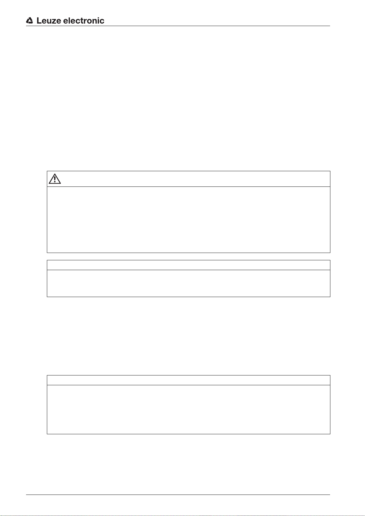
Table 1.1: Warning symbols, signal words and symbols
Pay attention to passages marked with this symbol. Failure to observe the provided instructions could lead to personal injury or damage to equipment.
Signal word for property damage
NOTE
Indicates dangers that may result in property damage if the measures for danger avoidance are not followed.
Symbol for tips
Text passages with this symbol provide you with further information.
About this document
Table 1.2: Operating on the display
Main Settings
Digital IOs
Symbols for action steps
Text passages with this symbol instruct you to perform actions.
1.2 Terms and abbreviations
Table 1.3: Terms and abbreviations
DTM (Device Type Manager) Software device manager of the sensor
IO Input Output
FB (First Beam) First beam
FDT (Field Device Tool) Software frame for management of device managers (DTM)
Bold text
Indicates that this field is currently selected and appears highlighted in
the receiver display.
Normal text
Indicates that this field is not currently selected (is not highlighted in the
receiver display).
LB (Last Beam) Last beam
TIB (Total Interrupted Beams) Total of interrupted beams
n Number of all logical beams of a light curtain; dependent on the
selected measurement field length and resolution as well as the
beam mode (parallel- / diagonal- / crossed-beam scanning)
IODD IO Device Description (IODD file for IO-Link interface)
Description of the device for the control
GUI (Graphical User Interface) Graphical user interface
PLC Programmable Logic Control
(corresponds to Programmable Logic Controller (PLC))
Response time per beam Length of time for the evaluation of a beam
Leuze electronic CSL 710 6
Page 7

About this document
Resolution The minimum size of an object that can be reliably detected.
With parallel-beam evaluation, the smallest object to be
detected corresponds to the sum of beam spacing and optic
diameter.
Delay before start-up Duration between the switching on of the supply voltage and
the start of operational readiness of the light curtain
Function reserve (sensitivity adjustment)
Ratio of the optical reception power set during the teach event
and the minimum light quantity required to switch the individual
beam. This compensates for the light attenuation caused by
dirt, dust, smoke, humidity and vapor.
High function reserve = low sensitivity
Low function reserve = high sensitivity
Measurement field length Optical detection range between the first and last beam
Beam spacing Center-to-center spacing between two beams
Cycle time Sum of the response times of all beams of a light curtain plus
the duration of the internal evaluation.
Cycle time =
number of beams x response time per beam + evaluation time
Leuze electronic CSL 710 7
Page 8
2 Safety
This sensor was developed, manufactured and tested in line with the applicable safety standards. It corresponds to the state of the art.
2.1 Intended use
The device is designed as a switching and object-detecting, configurable, multi-sensor unit.
Areas of application
The switching light curtain is designed for the detection of objects for the following areas of application in
handling and warehousing systems, the packaging industry or a comparable environment:
• Object detection
• Projection monitoring
• Height monitoring or packet sorting
• Area monitoring
• Hole recognition
CAUTION
Observe intended use!
Only operate the device in accordance with its intended use.
The protection of personnel and the device cannot be guaranteed if the device is operated in a manner
not complying with its intended use.
Leuze electronic GmbH + Co. KG is not liable for damages caused by improper use.
Read the original operating instructions before commissioning the device.
Knowledge of the original operating instructions is an element of proper use.
Safety
NOTICE
Comply with conditions and regulations!
Observe the locally applicable legal regulations and the rules of the employer's liability insurance asso-
ciation.
2.2 Foreseeable misuse
Any use other than that defined under “Intended use” or which goes beyond that use is considered
improper use.
In particular, use of the device is not permitted in the following cases:
• Rooms with explosive atmospheres
• Circuits relevant to safety
• Operation for medical purposes
NOTICE
Do not modify or otherwise interfere with the device!
Do not carry out modifications or otherwise interfere with the device.
The device must not be tampered with and must not be changed in any way.
The device must not be opened. There are no user-serviceable parts inside.
Repairs must only be performed by Leuze electronic GmbH + Co. KG.
2.3 Competent persons
Connection, mounting, commissioning and adjustment of the device must only be carried out by competent
persons.
Leuze electronic CSL 710 8
Page 9

Prerequisites for competent persons:
• They have a suitable technical education.
• They are familiar with the rules and regulations for occupational safety and safety at work.
• They are familiar with the original operating instructions of the device.
• They have been instructed by the responsible person on the mounting and operation of the device.
Certified electricians
Electrical work must be carried out by a certified electrician.
Due to their technical training, knowledge and experience as well as their familiarity with relevant stan-
dards and regulations, certified electricians are able to perform work on electrical systems and independently detect possible dangers.
In Germany, certified electricians must fulfill the requirements of accident-prevention regulations BGV A3
(e.g. electrician foreman). In other countries, there are respective regulations that must be observed.
2.4 Exemption of liability
Leuze electronic GmbH + Co. KG is not liable in the following cases:
• The device is not being used properly.
• Reasonably foreseeable misuse is not taken into account.
• Mounting and electrical connection are not properly performed.
• Changes (e.g., constructional) are made to the device.
Safety
Leuze electronic CSL 710 9
Page 10

3 Device description
X2X3
3
2 41
X1
5 6
3.1 General information
The light curtains of the CSL 710 series are designed as switching and object-detecting, configurable,
multi-sensor units. Depending on the configuration and model, the devices are suitable for a variety of
tasks with various resolutions and can be integrated in different control environments.
The total system of the light curtain consists of a transmitter and a receiver, including the connection and
interconnection cables.
• Transmitter and receiver are connected to one another via a synchronization cable.
• The integrated control panel with indicators and operational controls for configuring the total system
is located on the receiver.
• The shared power supply is provided via connection X1 on the receiver.
Device description
1 Transmitter
2 Receiver
3 IO Logic with control panel
4 Control (PLC)
5 Synchronization cable
6 Connection cable for supply voltage and communication interface
Figure 3.1: Total system in combination with a programmable logic control
3.2 General performance characteristics
The most important performance characteristics of the CSL 710 series are:
• Operating range up to 7000 mm
• Measurement field length from 150 mm to 2960 mm
• Beam spacings of 5 mm, 10 mm, 20 mm, 40 mm
• Response time 30 µs per beam
• Beam modes: parallel, diagonal, crossed-beam
• Status of beam areas 1 … 8
Status of the digital inputs/outputs
• Local control panel with display
• Interfaces to the machine control:
• IO-Link:
Leuze electronic CSL 710 10
Page 11

Up to four digital inputs/outputs (configurable)
1
2
• Blanking of unnecessary beams
• Smoothing for interference suppression
• Block evaluation of beam areas
3.3 Connection technology
The transmitter and receiver feature an M12 connector with the following number of pins:
Device type Designation on device Plug/socket
Receiver X1 M12 plug, 8-pin
Receiver X2 M12 socket, 5-pin
Transmitter X3 M12 plug, 5-pin
3.4 Display elements
The display elements show the device status in operation and provide support during commissioning and
error analysis.
Located on the receiver is a control panel with the following display elements:
•two LEDs
• one OLED display (Organic Light-Emitting Diode), two-line
Device description
Located on the transmitter is the following display element:
•one LED
3.4.1 Operation indicators on the receiver control panel
Two function indicator LEDs are located on the receiver control panel.
1 LED1, green
2 LED2, yellow
Figure 3.2: LED indicators on the receiver
Table 3.1: Meaning of the LEDs on the receiver
LED Color State Description
1 Green ON (continuous
Light curtain ready (normal mode)
light)
Flashing see chapter 12.2
OFF Sensor not ready
2 Yellow ON (continuous
light)
All active beams free – with function reserve or configured as trigger slave without trigger pulses
Flashing see chapter 12.2
OFF At least one beam interrupted (object detected)
Leuze electronic CSL 710 11
Page 12
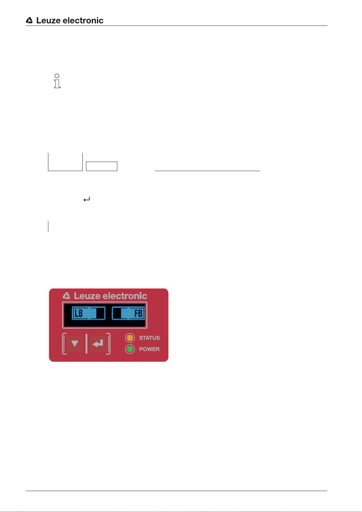
3.4.2 Display on the receiver control panel
1
234 5
Located on the receiver is an OLED display which serves as a function indicator.
Figure 3.3: OLED display on the receiver
The type of display on the OLED display is different for the following operating modes:
• Alignment mode
• Process mode
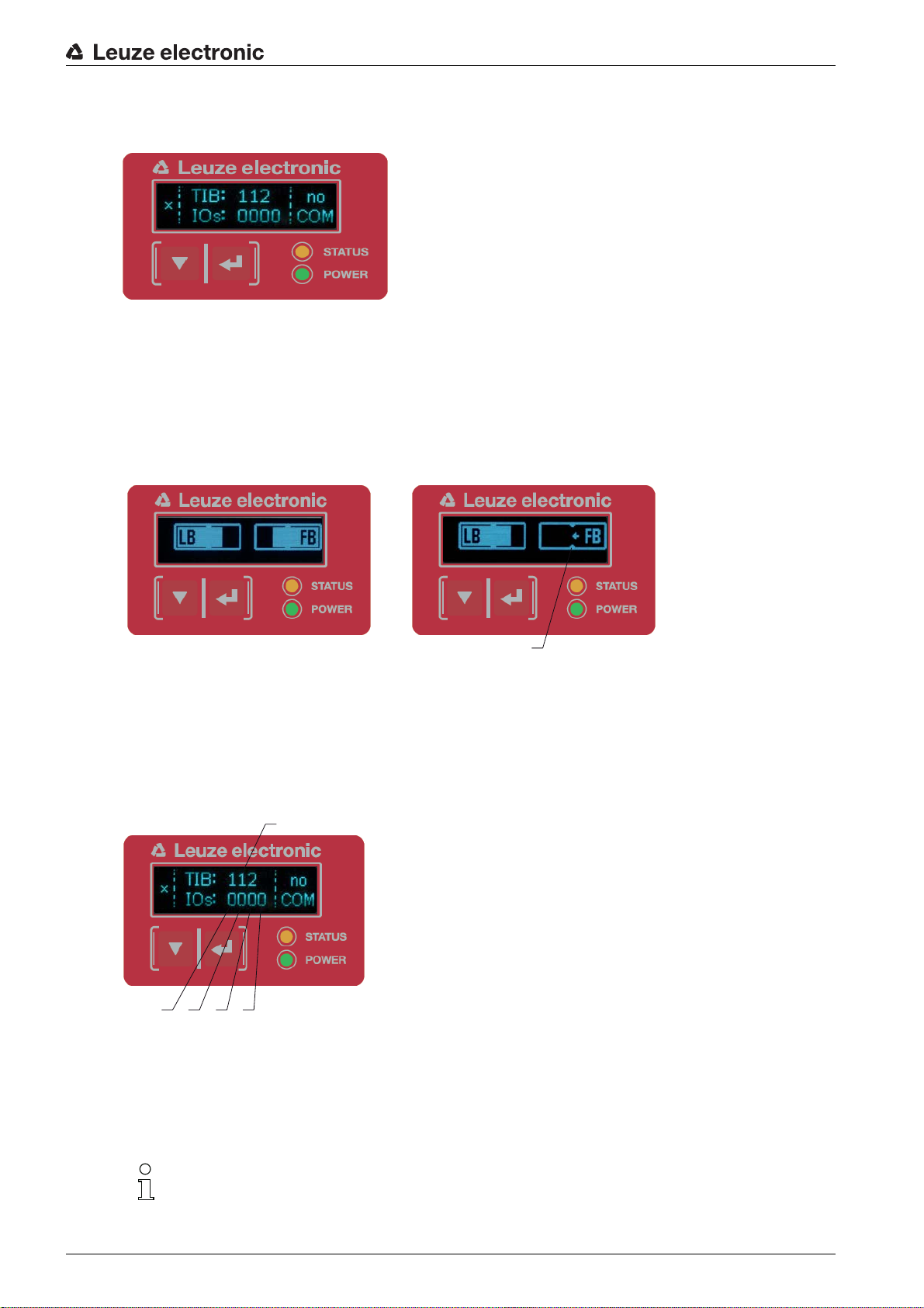
Display indicators in alignment mode
In alignment mode, the OLED display shows the received signal level of the first active logical beam (FB)
and of the last active logical beam (LB) via two bar graph indicators.
Device description
12
1 Evenly aligned light curtain
2 No reception signal from first beam (FB); good reception signal from last beam (LB)
3 Marker for the minimum signal level which is to be achieved
3
Figure 3.4: OLED display on the receiver in alignment mode
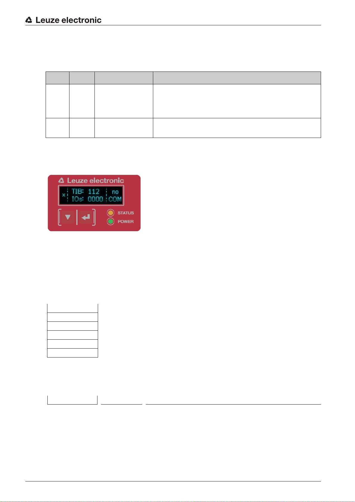
Display indicators in process mode
In process mode, the upper line shows the number of interrupted beams (TIB) and the lower line shows
the logic state of the digital outputs. The value to be displayed is configurable.
1 Total of interrupted beams
2 Logic state at pin 2 (0 = not active, 1 = active)
3 Logic state at pin 5 (0 = not active, 1 = active)
4 Logic state at pin 6 (0 = not active, 1 = active)
5 Logic state at pin 7 (0 = not active, 1 = active)
Figure 3.5: OLED display on the receiver in process mode
If the control panel is not used for several minutes, the display darkens and switches off. Press
a function button to again make the display visible. Settings for visibility, display duration, etc.
can be changed via the Display menu.
Leuze electronic CSL 710 12
Page 13
3.4.3 Operating indicators on the transmitter
Located on the transmitter is an LED which serves as a function indicator.
Table 3.2: Meaning of the LED on the transmitter
LED Color State Description
Device description
1GreenON
(continuous light or
Light curtain operates continuously with maximum measure-
ment frequency
flashing in sync with
the measurement)
OFF No communication with the receiver
Light curtain waits for external trigger signal
3.5 Operating elements on the receiver control panel
Located on the receiver below the OLED display is a membrane keyboard with two function buttons for
entering various functions.
Figure 3.6: Function buttons on the receiver
3.6 Menu structure of the receiver control panel
The following summary shows the structure of all menu items. In a given device model, only the actually
available menu items are present for entering values or for selecting settings.
Menu level 0
Level 0
Main Settings
Digital IOs
Analog Output
Display
Information
Exit
Menu “Main Settings”
Level 1 Level 2 Description
Commands Teach Reset Factory settings Exit
Leuze electronic CSL 710 13
Page 14

Level 1 Level 2 Description
Operational setting Filter depth (enter value)
Beam mode Parallel Diagonal Crossed-beam
Function reserve High Medium Low
Blanking teach Not active Active
Power-Up teach Not active Active
Smoothing (enter value)
IO-Link Bit rate COM3: 230.4 kbit/s COM2: 38.4 kbit/s
Data Storage Deactivated Activated
min = 1
max = 255
min = 1
max = 255
Menu “Digital IOs”
Level 1 Level 2 Description
IO Logic Positive PNP Negative NPN
IO Pin 2
IO Pin 5
IO Pin 6
IO Pin 7
IO Function Trigger input Teach input Area output Warning output
Inversion Normal Inverted
Teach height Execute Exit
Area logic AND OR
Start beam (enter value)
End beam (enter value)
min = 1
max = 1774
min = 1
max = 1774
Device description
Menu “Display”
Level 1 Level 2 Description
Language English German French Italian Spanish
Operating mode Process mode Alignment
Visibility Off Dark Normal Bright Dynamic
Time unit (s) (enter value)
min = 1
max = 240
Menu “Information”
Level 1 Level 2 Description
Product name CSL710-R05-320.A/L-M12
Product ID Receiver part no. (e.g., 50119835)
Serial number Receiver serial number (e.g., 01436000288)
Tx.transmitter-ID Transmitter part no. (e.g., 50119407)
Tx.transmitter-SN Transmitter serial no. (e.g., 01436000289)
FW version e.g., 01.61
HW version e.g., A001
Kx version e.g., P01.30e
Leuze electronic CSL 710 14
Page 15

3.7 Menu navigation on the receiver control panel
The and buttons have different functions depending on the operating situation. These functions
are displayed at the left edge of the display above the icons.
3.7.1 Meaning of the display icons
Icon Position Function
Symbolizes that you can select the next parameter within a menu level by
First line
First line
Second line
Second line
pressing the button.
Symbolizes that you have reached the lowest menu level (not highlighted).
Symbolizes the respective, next menu level that you have not yet selected
(not highlighted).
Press the button to exit the menu level or the menu.
Device description
Second line
Second line
Second line
Second line
3.7.2 Level display
The display of bars between icons and text that span both lines indicates the open menu levels. The
example shows a configuration in the menu level 2:
Symbolizes the input mode.
The selected (highlighted) option field can be a fixed selection parameter or a
multi-digit input field. With a multi-digit input field, you can increase the active
digit by one with the button and use the button to switch from one
digit to the next.
Symbolizes the confirmation of a selection.
This icon appears when you complete an option field with the button.
Symbolizes the rejection of a selection.
This icon is accessed from the previous icon (check mark) by pressing
the button. This mode allows you to reject the current value or option
parameter by pressing the button.
Symbolizes the return to the selection.
This icon is accessed from the previous icon (cross) by pressing
the button. This mode allows you to reset the current value or option
parameter for the purpose of entering a new value or selecting an option
parameter by pressing the button.
Start Beam
End beam
Leuze electronic CSL 710 15
Page 16

3.7.3 Menu navigation
Main Settings
Digital IOs
Selects the next menu item (“Digital IOs”); the other menu items follow if pressed again.
Selects the highlighted submenu (“Main Settings”).
3.7.4 Editing value parameters
Start Beam
End beam
Device description
Selects the “Start Beam” menu item with the bright background.
Start beam
0001
Changes the value of the first digit (0).
Selects additional numbers for configuring values.
After entering the last number, the total value can be saved, rejected or reset.
Start beam
0010
Saves the new value (0010).
Changes the action mode; first and then appears on the second line.
If the selected option is not saved in the window above, but rather the action mode is selected with
the button, this means:
Leuze electronic CSL 710 16
Page 17

Start beam
0010
Rejects the current input value. The display returns to the higher-order menu level: Start Beam/
End Beam
If the action mode is selected with the button, this means:
Start beam
0010
Device description
Resets the current input value (0001) and allows the entry of new values.
3.7.5 Editing selection parameters
IO Logic
IO Pin 2
Selects the “IO Logic” menu item with the bright background.
IO Logic
Positive PNP
With each actuation, displays the next option on this menu level, i.e., the display switches
between:
• Negative NPN
• Positive PNP
Selects the “Positive PNP” menu item with the bright background.
Leuze electronic CSL 710 17
Page 18

Device description
IO Logic
Positive PNP
Changes the action mode; appears; subsequent actuation displays or again.
Saves the selected option “Positive PNP”.
Leuze electronic CSL 710 18
Page 19
4 Functions
1
This chapter describes the functions of the light curtain for adaptation to different applications and operating conditions.
4.1 Beam modes
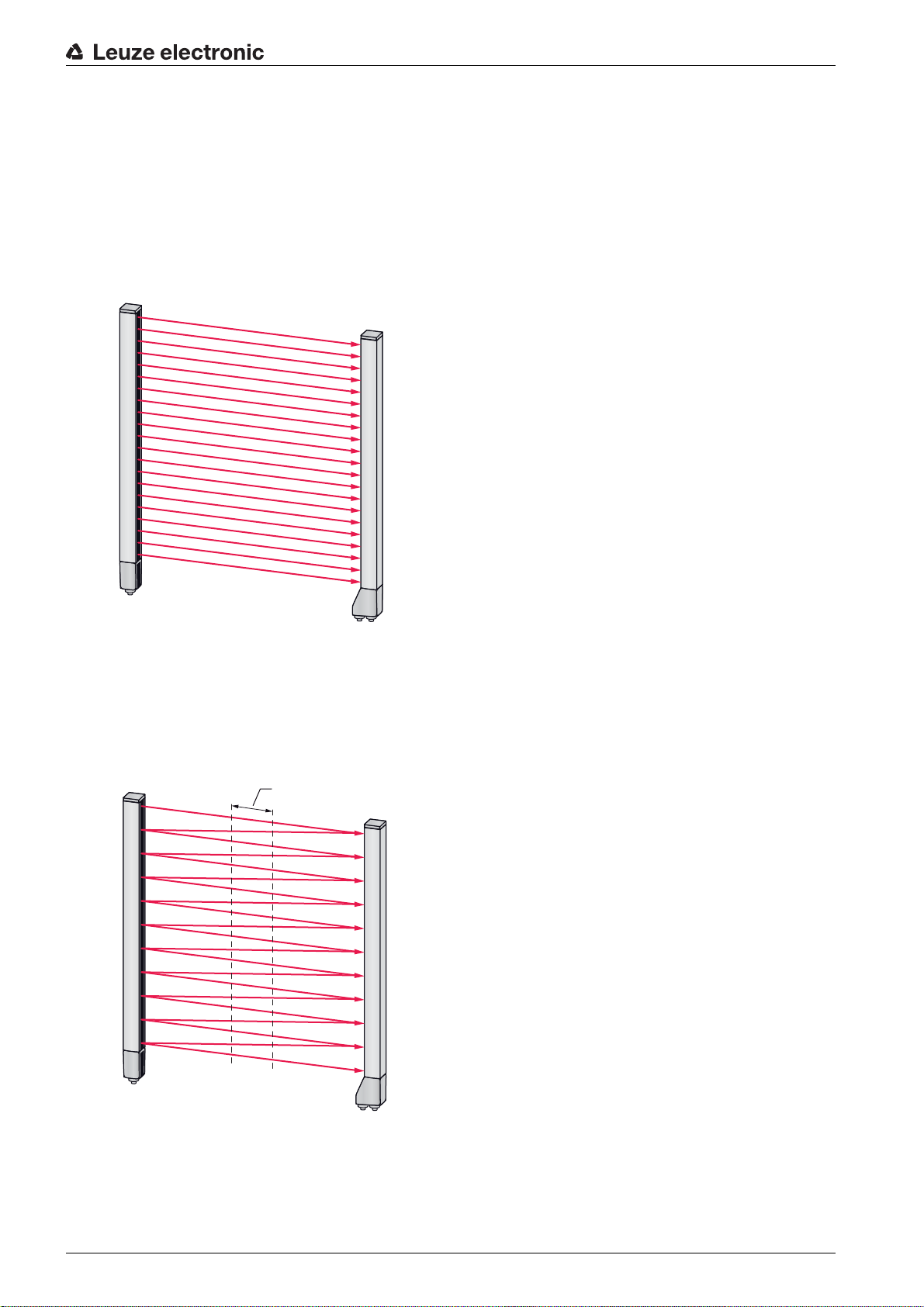
4.1.1 Parallel
In “parallel”-beam mode (parallel-beam scanning), the light beam of each transmitter LED is detected by
the directly opposing receiver LED.
Functions
Figure 4.1: Beam path in “parallel”
4.1.2 Diagonal
In “diagonal” beam mode, the light beam of each transmitter diode is received in succession both by the
directly opposing receiver diode as well as by the next receiver diode in the counting direction (i-1) (parallel
and diagonal beam path). This increases the resolution in the middle between the transmitter and receiver.
1 Area with increased resolution
Figure 4.2: Beam path in “diagonal”
Calculation
The number of beams for diagonal-beam scanning n
beam scanning n
Leuze electronic CSL 710 19
.
d
is calculated from the number of beams for parallel-
p
Page 20

Functions
nd2np1–=
1
Formula for calculating the number of beams for diagonal-beam scanning
n
[number] = number of beams for diagonal-beam scanning
d
n
[number] = number of beams for parallel-beam scanning
p
Example: 288 beams in parallel-beam scanning become 575 logical individual beams in diagonal-beam
scanning, which must be taken into account during evaluation functions. With a beam spacing of 5 mm,
this spacing is reduced to 2.5 mm in the center area.
The “diagonal” beam mode (diagonal-beam scanning) can be activated via the interface (see
chapter 9) or via the
Sensor Studio
configuration software (see chapter 11).
NOTICE
Minimum distance for diagonal-beam scanning!
For diagonal-beam scanning, the minimum distance that must be maintained between transmitter and
receiver changes, whereby the values vary depending on beam spacing (see chapter 15).
NOTICE
Teach after changing the beam mode!
Changing the beam mode changes the number of beams used for the evaluation. Perform a teach
after changing the beam mode (see chapter 8.2).
4.1.3 Crossed-beam
The “crossed-beam” mode (crossed-beam scanning) is available for increasing the resolution for an area
of the measurement field. In “crossed-beam” mode, the light beam of each transmitter LED is detected in
succession both by the directly opposing receiver LED as well as by the two adjacent receiver LEDs (i+1,
i-1).
1 Area with increased resolution
Figure 4.3: Beam path in “crossed-beam”
Leuze electronic CSL 710 20
Page 21

Functions
nk3np2–=
1
2
4
3
3
Calculation
The number of beams for crossed-beam scanning n
beam scanning n
.
k
is calculated from the number of beams for parallel-
p
Formula for calculating the number of beams for crossed-beam scanning
n
[number] = number of beams for crossed-beam scanning
K
[number] = number of beams for parallel-beam scanning
n
p
NOTICE
Minimum distance for crossed-beam scanning!
For crossed-beam scanning, the minimum distance that must be maintained between transmitter and
receiver changes, whereby the values vary depending on beam spacing (see chapter 15).
Example: 288 beams in parallel-beam scanning become 862 logical beams in crossed-beam scanning.
With a beam spacing of 5 mm, this spacing is reduced to 2.5 mm in the center area.
The “crossed-beam” mode (crossed-beam scanning) can be activated via the interface (see
chapter 9) or via the
Sensor Studio
configuration software (see chapter 11).
4.2 Blanking
If light curtains are installed such that existing frames / cross bars etc. continuously interrupt some beams,
these beams must be suppressed.
During blanking, beams that are not to be included in the evaluation are suppressed. The numbering of
the beams is not affected, i.e., the suppression of beams does not change the beam numbers.
1 Interrupted beams
2 Suppressed beams (blanking)
3 Free beams
4 Object present at the installation site
Figure 4.4: Beam states
Up to four adjacent beam areas can be suppressed.
The beams can be activated or suppressed via the interface, via the
Sensor Studio
configuration
software (see chapter 11) and partially via the operational controls on the receiver.
Leuze electronic CSL 710 21
Page 22

Functions
The behavior of each blanking area can be adapted to the requirements of the application:
Logical value of a blanking area Meaning in the application
No beams are blanked All beams of the device are included in the evaluation.
Logical value 0 for blanked beams All beams of the blanking area are taken into account
as interrupted beams (logical value 0) in the evaluation.
Logical value 1 for blanked beams All beams of the blanking area are taken into account
as free beams (logical value 1) in the evaluation.
Logical value is the same as the adjacent
beam with lower beam number
Logical value is the same as the adjacent
beam with higher beam number
All beams of the blanking area behave in the evaluation like the previous beam.
All beams of the blanking area behave in the evaluation like the subsequent beam.
For an example configuration, see chapter 10.3.
NOTICE
Teach after changing the blanking configuration!
Perform a teach after changing the blanking configuration (see chapter 8.2).
Auto blanking during teaching
If there are obstacles present in the measurement field at the installation site and at least one blanking
area is activated, interrupted beams can be mapped to the blanking area(s) during teaching. Existing
settings for the blanking areas are then overwritten (see chapter 8.2).
If no beams are interrupted during teaching, no blanking areas are configured.
Auto blanking cannot be used to detect transparent objects.
Deactivated beams are lost if the beam mode is changed while auto blanking is active.
NOTICE
Deactivate auto blanking in process mode!
Deactivate auto blanking in process mode.
Activate auto blanking only during commissioning of the device to suppress distracting objects.
NOTICE
Deactivate auto blanking during Power-Up Teach!
Deactivate auto blanking if “Power-Up Teach” is activated (see chapter 4.3).
NOTICE
Resetting all blanking areas!
To deactivate blanking areas, leave auto blanking active with at least the same number of blanking
areas.
Perform a new teach in a free measurement field.
To deactivate blanking with the
Sensor Studio
configuration software, configure the number of blank-
ing areas as zero and, at the same time, deactivate each area.
Perform a new teach.
Leuze electronic CSL 710 22
Page 23

4.3 Power-Up Teach
After applying operating voltage, the “Power-Up Teach” function performs a teach event when the device
is ready for operation.
• If the Power-Up teach is successful, the new teach values are adopted if they are different from the
previously stored teach values.
• If the Power-Up teach is not successful (e.g. object in the light path), the previously saved teach values are used.
The Power-Up teach event can be activated via the interface, via the receiver control panel and
via the
NOTICE
Deactivate auto blanking during Power-Up Teach!
Deactivate auto blanking if “Power-Up Teach” is activated.
NOTICE
No objects in the light path!
During “Power-Up Teach”, ensure that no beams are partially covered by an object.
Sensor Studio
Functions
configuration software (see chapter 11).
4.4 Smoothing
With the smoothing function, interrupted beams are then only taken into account in the evaluation if the set
minimum number of adjacent beams is reached at the same time.
Smoothing can be used, e.g., to suppress interference caused by spot soiling of the lens cover.
Smoothing “1” means that every interrupted beam is evaluated and the device switches.
Figure 4.5: Smoothing configuration “1” – device switches
If smoothing is set to a value of “3”"
Leuze electronic CSL 710 23
Page 24

Functions
Figure 4.6: Smoothing configuration “3”, but a maximum of two adjacent beams interrupted – device
does not switch
Figure 4.7: Smoothing configuration “3” and three or more adjacent beams interrupted – device switches
NOTICE
Configuration values for smoothing!
Values from 1 to 255 can be entered for smoothing.
4.5 External triggering
Trigger input
For an exact time assignment, it is possible to start the measurement cycle of a light curtain in a targeted
manner by means of a pulse at the trigger input.
Leuze electronic CSL 710 24
Page 25
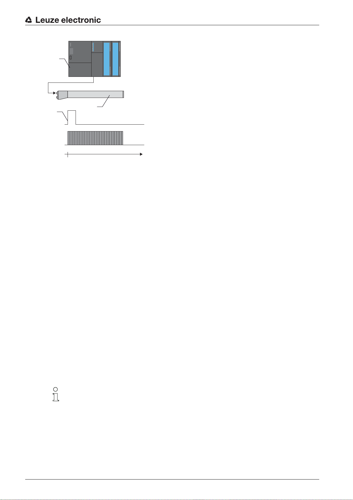
1PLC
0
LV 1
t [ms]
2
1
3
2 Light curtain 1
3 Trigger signal (PLC)
Figure 4.8: Activation via external trigger
Functions
4.6 Block evaluation of beam areas
This function can be used to define beam areas and evaluate them individually.
4.6.1 Defining beam area
To read out the beam states block-wise with an 8-bit telegram, the individual beams can be mapped to up
to eight areas independent of the maximum beam number. The individual beam information of grouped
beams is linked to a logical bit, i.e., each area is represented as 1 bit.
The number of beams in an area can be freely defined. However, the beams must be adjacent to one
another. The start beam and the end beam are to be defined as well as the conditions for switching of the
area.
4.6.2 Autosplitting
The beams of the device are automatically divided into the selected number of areas of the same size. The
states of the areas generated in this way can be read out in the process data by means of the “Evaluation
function” parameter.
Procedure:
• Select logic combination of the beams within the areas (logical AND / logical OR)
• Define number of desired areas
The autosplitting configuration can be defined via the interface (see chapter 9) or via the
Sensor Studio
configuration software (see chapter 11).
4.6.3 Mapping beam area to switching output
If grouping individual beams or if creating a block, the beam state of any number of adjacent beams (area)
Leuze electronic CSL 710 25
can be signaled at a switching output.
Page 26
Functions
The following options are possible here:
• To use a specific, single beam for the evaluation, e.g., as trigger signal for a primary control.
• To group the complete measurement field into one switching area and thereby signal at the switching
output whether an object (at any position) is located in the measurement field.
• To configure up to eight switching areas for a reference check or height monitoring; in many cases,
this can make beam-data processing in the primary programmable logic control (PLC) unnecessary.
The switching conditions for the areas can be either AND or OR linked:
Logic function
Group bit (area status)
[logic 1/0]
AND 1 If all beams mapped to the area are interrupted
0 If at least one beam is not interrupted in the selected area
OR 1 If at least one beam is interrupted in the selected area
0 If none of the beams mapped to the area are interrupted
Areas may be sequential or overlapping. A maximum of 8 areas are available.
The switching behavior or the conditions for switching a beam area on and off can be defined via
the interface (see chapter 9) or via the
Sensor Studio
configuration software (see chapter 11).
For an example configuration, see chapter 10.1.
Example for the configuration of an OR or AND link for a light curtain with 32 beams
OR AND
Start beam 1 1
End beam 32 32
Switch-on condition 1 beam interrupted 32 beams interrupted
Switch-off condition 0 beams interrupted 31 beams interrupted
The following figure shows how the beam areas can be arranged directly next to one another or freely overlapping.
Leuze electronic CSL 710 26
Page 27

Functions
1
160
1
1
5
2
6
24
3
15
157
4
140
160
1 Beam area 1
2 Beam area 2
3 Beam area 3
4 Beam area 4
Figure 4.9: Beam areas
For a mapping of previously defined beam areas to, e.g., four switching outputs (Q1 to Q4), see
chapter 10.1.
NOTICE
Increased number of logical beams for the diagonal- or crossed-beam function!
Take into account the (increased) number of beams if the “diagonal”- or “crossed-beam” mode is acti-
vated (see chapter 4.1.2 or see chapter 4.1.3).
4.6.4 Teach height area
With the “Teach height area” function, it is possible to teach in up to eight height areas, e.g. for height monitoring or sorting packets. In many cases, this saves time for programming.
• A maximum of eight height areas are available.
• A height area is automatically defined using an object.
When teaching a height area, all free beams above or below the object are combined into one height
area. Therefore, the object cannot be located in the center of the measurement field length; the first
or last beam must be interrupted.
Leuze electronic CSL 710 27
Page 28

1 Teaching height area 1
1 2
2 Teaching height area 2
Figure 4.10: Teaching the height area with the “Teach in height area”
Functions
• To define the entire beam area as a height area, teaching of the height area is performed without an
object (all beams free).
Figure 4.11: Teaching of the total beam area as height area without object
• The switching behavior or the conditions for switching the height area on or off via the “Teach height
area” function is permanently defined as OR.
• Every IO pin can be assigned to a height area via the receiver control panel.
Example: Digital IOs > IO Pin 2 > Teach height > Execute
On the receiver control panel, the “Teach height area” function is activated via the Teach height
menu item. Example: Digital IOs > IO Pin 2 > Teach height > Execute
If the “Teach height area” function is activated via the receiver control panel, the IO pins are auto-
matically assigned to the height areas.
Leuze electronic CSL 710 28
Page 29
Example configurations for the assignment of previously defined height areas to switching outputs Q1 to
Q4:
• see chapter 10.1 "Example configuration - Mapping of beams 1 … 32 to output pin 2"
• see chapter 10.2 "Example configuration – Teach height area"
4.7 Switching outputs
4.7.1 Light/dark switching
The behavior of switching outputs Q1 to Q4 (or Q1 to Q2) can be configured with respect to light/dark
switching. The setting ex works is “light switching”, i.e., the outputs are activated if the light paths are free
and become inactive if an object is detected in the measurement field.
The output behavior can be changed to “dark switching” via the interface (see chapter 9), via the
receiver control panel and via the
4.7.2 Time functions
Each of the individual switching outputs can be assigned one of the time functions described in the
following table.
Sensor Studio
Functions
configuration software (see chapter 11).
The accuracy of the switching delay is dependent on the measurement frequency. Observe this
especially in cascaded operation.
Time function Selectable
Duration
Start-up delay
with re-trigger
Switch-off delay
with re-trigger
Pulse stretching 0 … 65000 ms Minimum time that the state of the output is retained
Pulse suppression
with re-trigger
0 … 65000 ms Time that the sensor delays the start-up process after
0 … 65000 ms Time that the sensor delays the switching back of the
0 … 65000 ms Minimum time that a measurement signal must be pres-
Description
detecting an object.
By means of a start-up delay, it is possible to suppress,
e.g., upward-protruding packaging remnants (stretch
wrap, etc.) during pallet height monitoring.
output if the object leaves the detection range.
independent of what the sensor detects during this time.
Pulse stretching is necessary for, e.g., hole recognition if
the PLC cycle time does not register short pulses.
ent in order for the output to switch. Short interference
pulses are thereby suppressed.
The various time functions can be configured via the interface (see chapter 9) or via the
Sensor Studio
configuration software (see chapter 11).
4.8 Interference suppression (filter depth)
To suppress any faulty measurement values that may occur due to interference (ambient light, electromagnetic fields, …), the filter depth of the light curtain can be increased.
“Filter depth” means that an interrupted/free beam is not included in the further data evaluation until the
same beam status is recorded for the set number of measurement cycles.
Filter depth “1” = the beam states of each measurement cycle are output.
Filter depth “3” = only those beam states that were stable over three measurement cycles are output.
Leuze electronic CSL 710 29
Page 30

Functions
The configuration of the filter depth can be defined via the interface (see chapter 9) or via the
Sensor Studio
configuration software (see chapter 11).
Leuze electronic CSL 710 30
Page 31
5 Applications
The following typical applications with corresponding function (see chapter 4) exist for the switching light
curtain.
5.1 Object counting
Applications
Figure 5.1: Object counting
For object counting, the switching output is assigned to an IO pin. The evaluation is done by an external
program.
Function:
For more precise object counting, e.g. when several small objects are located in the measurement field,
you can select crossed-beam scanning and divide the measurement field into up to eight areas. The states
of the areas generated are read out in the process data by means of the
Function:
Function:
mapping beam area to switching output
beam mode: crossed beam
autosplitting
and
evaluation function (process data content)
Evaluation function
parameter.
Leuze electronic CSL 710 31
Page 32

5.2 Height monitoring and sorting of packets
Applications
Figure 5.2: Sorting packets
Packets can be sorted into up to eight height classes.
Example: sorting into classes S (small), M (medium) and L (large):
• Teach the three height areas (see chapter 4.6.4).
• Assign a switching output to every height area (see chapter 4.6.3).
Function:
teach height area
Leuze electronic CSL 710 32
Page 33

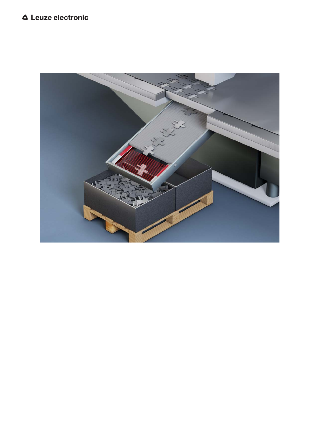
5.3 Hole recognition
Applications
Figure 5.3: Hole recognition
For hole recognition within a web material, a beam area must be defined over the area to be monitored
and mapped to an output. All beams in this area are interrupted. If a beam becomes “free” due to a flaw in
the material, the output switches.
Function:
block evaluation of beam areas
(see chapter 4.6)
Leuze electronic CSL 710 33
Page 34

6 Mounting and installation
6.1 Mounting the light curtain
NOTICE
No reflective surfaces, no mutual interference!
Avoid reflective surfaces near the light curtains.
Objects may otherwise not be precisely detected due to halation.
Ensure sufficient distance, suitable positioning or partitioning.
Optical sensors (e.g., other light curtains, photoelectric sensors, etc.) must not interfere with one
another.
Avoid interference from outside light (e.g., from flash lamps, direct sunlight) on the receiver.
Mount the transmitter and receiver as follows:
Select the fastening type for transmitter and receiver.
- Fastening via the T-groove on one side of the standard profile (see chapter 6.3).
- Fastening via the rotating bracket on the ends of the profile (see chapter 6.4).
- Fastening via the swiveling mounting brackets or parallel brackets (see chapter 6.5).
Have a suitable tool at hand and mount the light curtain in accordance with the notices regarding the
mounting locations.
Mount the transmitter and receiver at the same height or with the same housing reference edge, free of
tension and with the base in full contact with the mounting surface.
Mounting and installation
NOTICE
Must be observed!
For horizontally mounted measuring light curtains with lengths of more than 2,000 mm, use an addi-
tional mounting bracket in the middle of the light curtain.
The optical surfaces of transmitter and receiver must be parallel to and opposite one another.
The transmitter and receiver connections must point in the same direction.
Secure transmitter and receiver against turning or sliding.
Leuze electronic CSL 710 34
Page 35

1 Same height position / upper edge
4 3
1
2
2
a) b) c) d)
2 Parallel alignment
3 Receiver
4 Transmitter
Figure 6.1: Arrangement of transmitter and receiver
Mounting and installation
To achieve the maximum operating range limit, transmitter and receiver must be aligned with one
another as accurately as possible.
After mounting, you can electrically connect (see chapter 7) and start up (see chapter 8) the light curtain.
6.2 Definition of directions of movement
The following terms for alignment movements of the light curtain around one of its individual beams are
used:
a Sliding: movement along the longitudinal axis
b Turning: movement around the longitudinal axis
c Tilting: lateral turning movement diagonal to the lens cover
d Pitching: lateral turning movement in the direction of the lens cover
Figure 6.2: Directions of movement during alignment of the light curtain
Leuze electronic CSL 710 35
Page 36
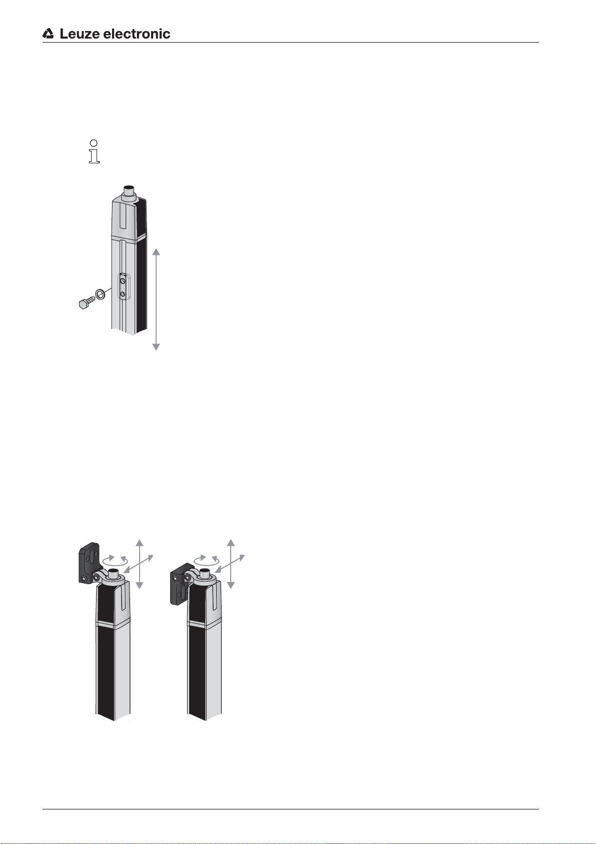
6.3 Fastening via sliding blocks
By default, transmitter and receiver are delivered with two sliding blocks (three sliding blocks for measurement field lengths of more than 2,000 mm) each in the side groove (see chapter 16).
Fasten transmitter and receiver to the machine or system via the lateral T-groove with M6 screws.
Sliding in the direction of the groove is possible, but turning, tilting and pitching is not.
Mounting and installation
Figure 6.3: Mounting via sliding blocks
6.4 Fastening via swivel mount
When mounting with the BT-2R1 swivel mount (see table 16.7), sold separately, the light curtain can be
aligned as follows:
• Sliding through the vertical threaded holes in the wall plate of the swivel mount
• Turning by 360° around the longitudinal axis by fixing on the screw-on cone
• Tilting around main axis
• Pitching through horizontal threaded holes in the wall mounting
The wall mounting through threaded holes makes it possible to lift the mounting bracket after the screws
have been loosened over the connection cap. Therefore, the mounting brackets do not need to be
removed from the wall when exchanging the device. Loosening the screws is sufficient.
Figure 6.4: Mounting via swivel mount
Leuze electronic CSL 710 36
Page 37

Mounting and installation
One-sided mounting on the machine table
The sensor can be mounted directly on the machine table via an M5 screw on the blind hole in the end
cap. On the other end, a BT-2R1 swivel mount can be used, for example, so that turning movements for
alignment are possible despite the fact that the sensor is mounted on one side.
NOTICE
Avoid reflection bypasses at the machine table!
Make sure that reflections on the machine table and in the vicinity are prevented reliably.
Figure 6.5: Mounting directly on the machine table
6.5 Fastening via swiveling mounting brackets
When mounting with the BT-2SSD/BT-4SSD or BT-2SSD-270 swiveling mounting brackets (see
table 16.7), sold separately, the light curtain can be aligned as follows:
• Sliding in the direction of slot
• Turning +/- 8° around the longitudinal axis
The BT-SSD (see figure 15.5) swiveling mounting brackets are also equipped with a vibration damper.
Leuze electronic CSL 710 37
Page 38
7 Electrical connection
7.1 Shielding and line lengths
The light curtains are equipped with modern electronics developed for industrial applications. In industrial
environments, a number of sources of interference may affect the light curtains.
In the following, information is provided on the EMC-compliant wiring of the light curtains and the other
components in the switch cabinet.
7.1.1 Shielding
NOTICE
General shielding information!
Avoid interference emissions when using power components (frequency inverters, …).
The necessary specifications under which the power component satisfies its CE Declaration of
Conformity can be found in the technical descriptions of the power components.
In practice, the following measures have proven effective:
Properly ground the total system.
Screw mains filter, frequency inverter, etc., flat to a galvanized mounting plate (thickness 3 mm) in the
switch cabinet.
Keep cable between mains filter and inverter as short as possible and twist cables.
Shield both ends of the motor cable.
Carefully ground all parts of the machine and of the switch cabinet using copper strips, ground rails or
grounding cables with large cross section.
Keep the length of the shieldless end of the cable as short as possible.
Guide the shielding untwisted to a terminal (no “RF braid”).
Electrical connection
NOTICE
Separate power and control cables!
Lay the cables for the power components (mains filter, frequency inverter, …) as far from the light cur-
tain cables as possible (distance > 30 cm).
Avoid laying power and light curtain cables parallel to one another.
Cable crossings should be laid as perpendicular as possible.
NOTICE
Lay cables close to grounded metal surfaces!
Lay the cables on grounded metal surfaces
This measure reduces interference coupling in the cables.
NOTICE
Avoid leakage currents in the cable shielding!
Carefully ground all parts of the machine.
Leakage currents arise from incorrectly implemented equipotential bonding.
You can measure leakage currents with a clip-on ammeter.
NOTICE
Star-shaped cable connections!
Ensure that the devices are connected in a star-shaped arrangement.
You thereby avoid mutual influences from various loads.
This prevents cable loops.
Leuze electronic CSL 710 38
Page 39

Electrical connection
Grounding the light curtain housings
Connect the transmitter housing and receiver housing of the light curtain to the protective conductor on
the FE machine star point via the PE screw on the grounding slot nut (see figure 7.1).
The cable should have an impedance as low as possible for high-frequency signals, i.e., be as short as
possible and have a large cross-sectional area (grounding strip, …).
Use a lock washer and check the penetration of the anodized layer.
Check the small Allen screw to ensure a secure connection between the grounding slot nut and housing.
The Allen screw is correctly tightened upon delivery from the factory.
If you have changed the position of the grounding slot nut or the PE screw, tighten the small Allen screw.
Figure 7.1: Connecting the ground potential to the light curtain
Example for shielding both ends of the connection cables from the switch cabinet to the light curtain
Ground the transmitter housing and receiver housing of the light curtain (see chapter "Grounding the
light curtain housings").
Clamp the shield in the switch cabinet flat to FE (see figure 7.2).
Use special shielding terminals (e.g., Wago, Weidmüller, …).
Figure 7.2: Connecting the cable shielding in the switch cabinet
Depicted shielding components from Wago, series 790 …:
- 790 … 108 screen clamping saddle 11 mm
- 790 … 300 busbar holder for TS35
Leuze electronic CSL 710 39
Page 40

Electrical connection
Example for shielding both ends of the connection cables from the PLC to the light curtain
Ground the transmitter housing and receiver housing of the light curtain (see chapter "Grounding the
light curtain housings").
Only lay shielded light curtain cables to the PLC.
Clamp the shield flat to FE in the PLC (see figure 7.3).
Use special shielding terminals (e.g., Wago, Weidmüller, …).
Make certain that the mounting rail is well grounded.
Figure 7.3: Connecting the cable shielding to the PLC
Depicted shielding components from Wago, series 790 …:
- 790 … 108 screen clamping saddle 11 mm
- 790 … 112 carrier with grounding foot for TS35
7.1.2 Cable lengths for shielded cables
Observe the maximum cable lengths for shielded cables.
Table 7.1: Cable lengths for shielded cables
Connection to the CSL 710 Interface Max. cable length Shielding
PWR IN/digital IO, IO-Link X1 20 m required
Synchronization cable X2/X3 20 m required
Designation of the interface connections: see chapter 7.3 "Device connections"
7.2 Connection and interconnection cables
Use only the cables listed in the accessories (see chapter 16) for all connections (connection
cable, interconnection cable, cable between transmitter and receiver).
Use only shielded cables for the cable between transmitter and receiver.
Leuze electronic CSL 710 40
Page 41

NOTICE
X1-1
X1-6/7
GND
18 - 30 VDC
100 mA (max. 250 mA)
X1-3
X1-2/5
10k
10k
X1-3
Competent persons and approved purpose!
Only allow competent persons to perform the electrical connection.
Select the functions so that the light curtain can be used as intended (see chapter 2.1).
7.3 Device connections
The light curtain is provided with the following connections:
Electrical connection
Device con-
Type Function
nection
X1 on receiver M12 connector,
Control interface and data interface:
8-pin
X2 on receiver M12 socket,
Synchronization interface
4-/5-pin
X3 on
transmitter
M12 connector,
5-pin
Synchronization interface (for all controller types)
7.4 Digital inputs/outputs on connection X1
In the factory settings, the digital inputs/outputs are assigned with the following functions:
• IO 1 (pin 2): teach input
• IO 2 (pin 5): switching output (dark/inverted)
• IO 3 (pin 6): switching output (light/normal)
• IO 4 (pin 7): warning output
• Voltage supply
• Switching outputs and control inputs
• Configuration interface
Figure 7.4: Digital input/output schematic diagram
NOTICE
Single assignment of input functions!
Each input function may only be used one time. If multiple inputs are assigned the same function, mal-
functions may occur.
7.5 Electrical connection – CSL 710
NOTICE
Light curtain grounding!
Ground the light curtain before establishing an electrical connection or connecting the voltage supply
(see chapter "Grounding the light curtain housings").
Leuze electronic CSL 710 41
Page 42
1 Receiver (R)
PWR IN/OUT
X1 X
2
X3
1
2
3
4
1
2 Transmitter (T)
3 Connection cable (M12 socket, 8-pin), see table 16.3
4 Synchronization cable (M12 plug/socket, 5-pin), see table 16.4
Figure 7.5: Electrical connection – CSL 710
Electrical connection
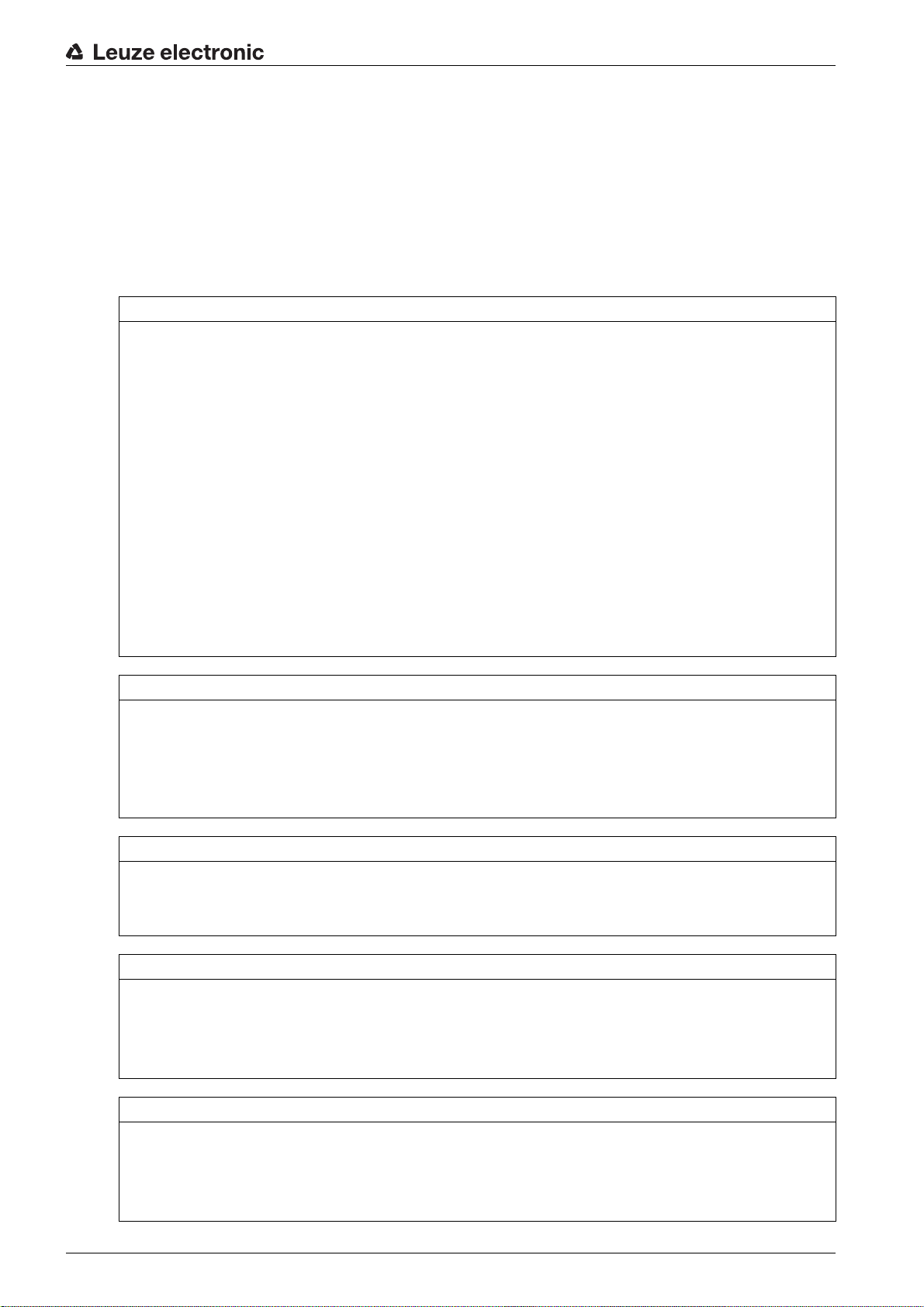
7.5.1 X1 pin assignment – CSL 710
Connect connection X2 to connection X3 using the appropriate synchronization cable.
Connect connection X1 to the voltage supply and the control using the appropriate connection cable.
8-pin, M12 plug (A-coded) for connecting to PWR IN/digital IO and IO-Link interface.
1 M12 plug (8-pin, A-coded)
Figure 7.6: X1 connection – CSL 710
Table 7.2: X1 pin assignment – CSL 710
Pin X1 - Logic and power on the receiver
1 VIN: +24 V DC supply voltage
2 IO 1: input/output (configurable)
Ex works: teach input (Teach In)
3 GND: ground (0 V)
Leuze electronic CSL 710 42
4 C/Q: IO-Link communication
5 IO 2: input/output (configurable)
Factory setting: switching output (dark/inverted)
Page 43

Pin X1 - Logic and power on the receiver
6 IO 3: input/output (configurable)
Factory setting: switching output (light/normal)
7 IO 4: input/output (configurable)
Factory setting: warning output
8 GND: ground (0 V)
Connection cables: see table 16.3.
7.5.2 X2/X3 pin assignment – CSL 710
5-pin, M12 socket/plug (A-coded) for the connection between transmitter and receiver.
1 2
Electrical connection
1 M12 socket X2 (5-pin, A-coded)
2 M12 plug X3 (5-pin, A-coded)
Figure 7.7: X2/X3 connection – CSL 710
Table 7.3: X2/X3 pin assignment – CSL 710
Pin X2/X3 - Transmitter and receiver
1 SHD: FE functional earth, shield
2 VIN: +24 V DC supply voltage
3 GND: ground (0 V)
4 RS 485 Tx+: synchronization
5 RS 485 Tx-: synchronization
Interconnection cables: see table 16.4.
7.6 Electrical supply
With regard to the data for the electrical supply, see table 15.6.
Leuze electronic CSL 710 43
Page 44

8 Starting up the device - Basic configuration
The basic configuration includes the alignment of transmitter and receiver and the basic configuration
steps via the receiver control panel.
The following optional basic functions are available for operation and configuration via the receiver control
panel:
• Define digital inputs/outputs
• Defining the filter depth
• Defining the display properties
• Changing the language
• Product information
• Resetting to factory settings
8.1 Aligning transmitter and receiver
NOTICE
Alignment during commissioning!
The alignment performed during commissioning should only be performed by qualified personnel.
Observe the data sheets and mounting instructions of the individual components.
Starting up the device - Basic configuration
Prerequisites:
• The light curtain has been mounted (see chapter 6) and connected (see chapter 7) correctly.
Switch on the light curtain.
NOTICE
Alignment mode!
When switched on for the first time ex works, the light curtain automatically starts in process mode.
You can switch from process mode to alignment mode via the control panel.
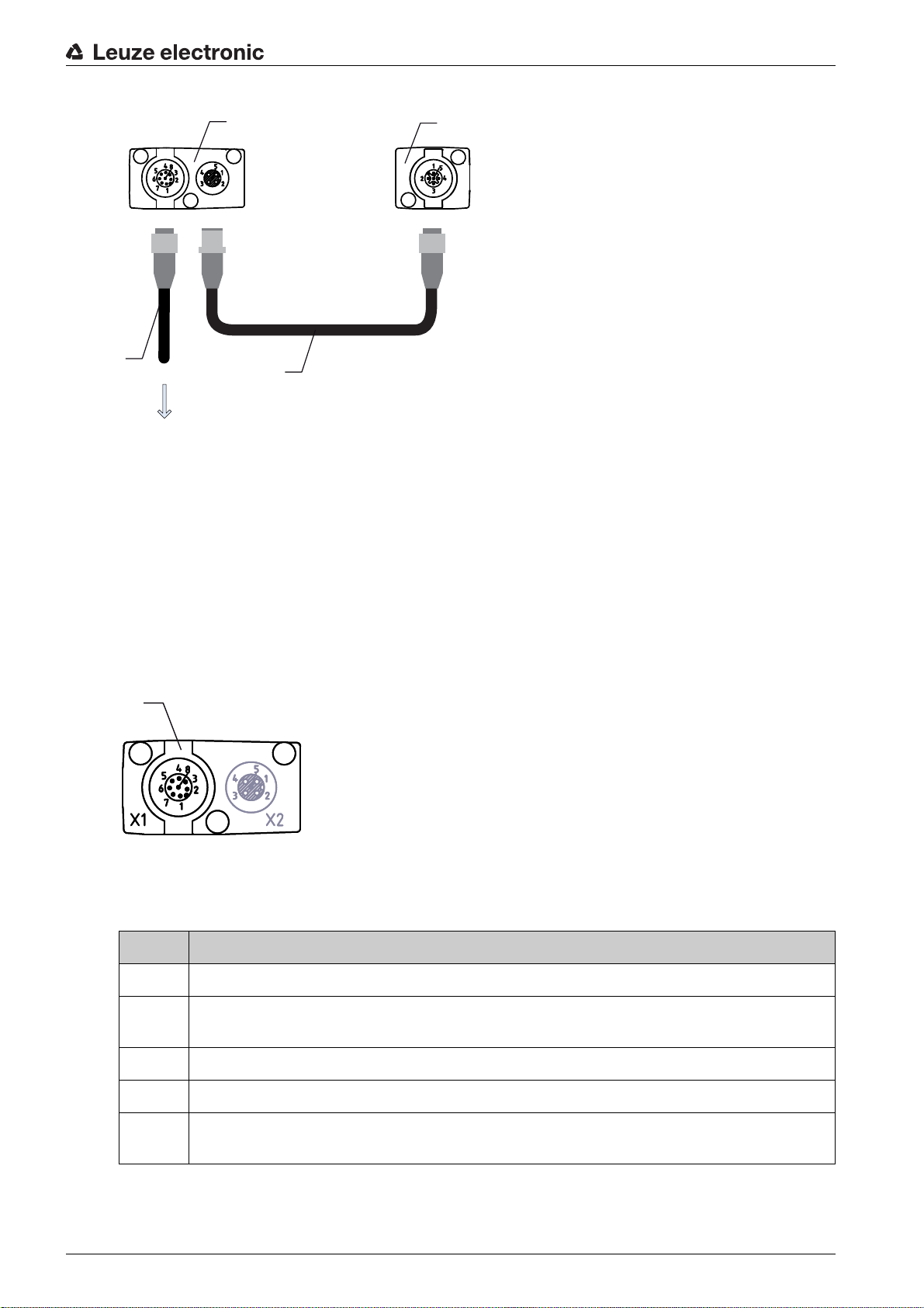
Check whether the green LEDs on the receiver control panel and transmitter illuminate continuously.
The display shows the alignment state of the first beam (FB) and last beam (LB) via two bar graph indicators.
Figure 8.1: Example: display showing an incorrectly aligned light curtain
Loosen the fastening screws of the transmitter and receiver.
Loosen the screws only enough so that the devices can just be moved.
Turn or slide the transmitter and receiver until the optimum position is reached and the bar graph indi-
cators show the maximum values for the alignment.
Leuze electronic CSL 710 44
Page 45
Starting up the device - Basic configuration
NOTICE
Minimum sensitivity of the sensor!
In order to perform a teach, a minimum level must be reached in the bar graph indicator (mark in the
middle of the display).
Figure 8.2: Display showing an optimally aligned light curtain
Tighten the fastening screws of the transmitter and receiver.
Transmitter and receiver are aligned.
Switching to process mode
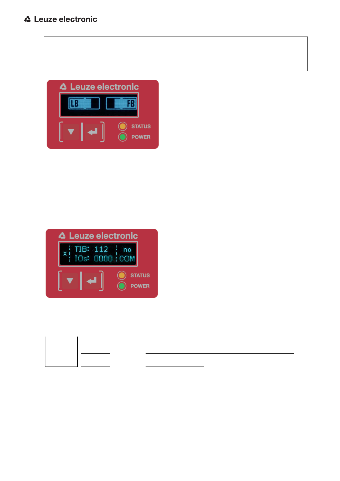
After aligning, switch to process mode.
Select Display > Mode > Process mode.
The display in the receiver of the light curtain shows the process mode states with the total of interrupted
beams (TIB) and the logic states of the digital inputs/outputs (digital IOs).
Figure 8.3: Display showing the process mode state of the light curtain
The structure of the configuration in the receiver control panel menu is as follows:
Level 0 Level 1 Level 2 Description
Display
Language English German French Spanish Italian
Operating
mode
Process mode Alignment
Switching to alignment mode
You can switch from process mode to alignment mode via the menu.
Select Display > Mode > Alignment.
The structure of the configuration in the receiver control panel menu is as follows:
Leuze electronic CSL 710 45
Page 46
Level 0 Level 1 Level 2 Description
Display
Language English German French Spanish Italian
Operating
mode
The next configuration step is teaching the environmental conditions (teach).
8.2 Teaching the environmental conditions
During teaching, the system checks whether the signals of all beams are within a certain corridor.
This means that a teach event generally regulates all beams to the preset function reserve (or sensitivity)
for the current operating range. This ensures that all beams exhibit an identical switching behavior.
NOTICE
Conditions for performing a teach!
When teaching without preconfigured blanking areas, the light path must always be completely free.
A teaching error will otherwise occur.
In this case, remove the obstacles and repeat the teach.
If the light path is partially interrupted by structural elements, the permanently interrupted beams can
be suppressed by means of blanking (
this case.
To automatically suppress the affected beams during teaching, configure the number of blanking
areas via the configuration software
Sensor Studio
Process mode Alignment
auto blanking
function). Interrupted beams are “deactivated” in
(see chapter 11).
Starting up the device - Basic configuration
The configuration can be performed via the interface (see chapter 9) or via the
Sensor Studio
configuration software (see chapter 11).
You can choose whether the teach values are to be stored permanently or only temporarily (while
the operating voltage is applied). The configuration ex works is for permanent (non-volatile) stor-
age.
A teach event can be performed both directly from process mode as well as from alignment
mode.
NOTICE
Execute teach after changing the beam mode!
Always perform a teach after changing the beam mode (parallel-/diagonal-/crossed-beam scanning)
as well.
Prerequisites:
• The light curtain must be correctly aligned (see chapter 8.1).
• The bar graph indicator must show a minimum level.
You can use one of the following teach types:
Teach via receiver control panel (see chapter 8.2.1).
Teach via teach input (see chapter 8.2.2).
Teach via interface (IO-Link, see chapter 9).
Teach via
Sensor Studio
configuration software (see chapter 11).
Leuze electronic CSL 710 46
Page 47
8.2.1 Teach via receiver control panel
If blanking areas are configured via the configuration software interface, a teach event is performed that
takes these blanking areas into account (blanking teach or auto blanking, see chapter 4.2).
During a blanking teach or auto blanking, an “additional distance” is always added to the beams
detected as interrupted. Safer operation is thereby achieved, e.g., in the case of vibrating guides,
etc., in the “blanked” area.
Optimization of the blanked beams is to be performed via a software interface configuration.
A maximum of four adjacent areas of suppressed beams (blanking areas) can be configured.
The structure of the configuration in the receiver control panel menu is as follows:
Level 0 Level 1 Level 2 Description
Main Settings
Commands Teach Reset Factory settings
Select Main Settings > Command > Teach.
Press the button to execute the teach.
The display shows
Starting up the device - Basic configuration
Wait...
If the teach was started while in process mode, the display returns to the process mode display after a
successful teach (see chapter 8.1).
If the teach was started from alignment mode, the display returns to the bar graph indicator following a
successful teach and shows the received signal level of the first beam (FB) and the last beam (LB) (see
chapter 8.1).
If teach is successful, both bars display the maximum value.
Figure 8.4: Display after successful teach
If no bars are visible in the bar graph indicator for the first beam (FB) and the last beam (LB), an error has
occurred. It is possible, e.g., that the reception signal is too low. You can correct errors according to the
error list (see chapter 12).
Power-Up Teach
After applying operating voltage, the “Power-Up Teach”"
The structure of the configuration in the receiver control panel menu is as follows:
Leuze electronic CSL 710 47
Page 48

Level 0 Level 1 Level 2 Description
Main Settings
Commands Teach Reset Factory settings
Operational setting
Filter depth
Beam mode
Function reserve
Blanking teach
Power-Up Teach Not active Active
Select Main Settings > Operation Settings > Power-Up Teach > Active.
8.2.2 Teaching via a control signal from the control
Teach input (Teach In)
This input can be used to perform a teach following initial commissioning, change of the alignment or
during operation. During this procedure, the transmitter and receiver adjust themselves to the maximum
function reserve according to the distance.
To trigger a teach, a pulse must be applied on connection X1 on the receiver IO1 = pin 2 (factory setting)
for longer than 20 ms … but less than 80 ms.
Depending on the configuration (PNP or NPN), this corresponds to the following signal response:
Starting up the device - Basic configuration
1
High
Low
1 Teach is performed here
Figure 8.5: Control signals for line teach with PNP configuration
1
High
Low
1 Teach is performed here
Figure 8.6: Control signals for line teach with NPN configuration
Performing a teach via the line input
Prerequisites:
• The light curtain must be correctly aligned (see chapter 8.1).
• A connection must be established between PLC and the line input (teach-in).
Send a teach signal to the teach input via th e control (s e e chapter "Teach input (Teach In)" for the data)
to trigger a teach.
The display on the receiver control panel shows
Wait...
Following a successful teach, the display switches back to the bar graph (alignment mode).
Leuze electronic CSL 710 48
Page 49

If teach is successful, both bars display the maximum value.
Figure 8.7: Display after successful teach
The next configuration step is to check the alignment.
8.3 Check alignment
Prerequisites:
• The light curtain must first be correctly aligned and a teach must be performed.
Check whether the green LEDs on the receiver control panel and transmitter illuminate continuously.
Use the bar graph indicator to check whether the light curtain is optimally aligned, i.e., whether the max-
imum is reached for both the first beam (FB) and the last beam (LB) in the bar graph indicator.
Use the bar graph indicator to check the optimum alignment of the light curtain if you have corrected an
error that occurred.
Starting up the device - Basic configuration
The next configuration steps:
• Perform extended configurations on the receiver control panel if necessary (see chapter 8.5)
• Starting up the CSL 710 light curtains (see chapter 9)
8.4 Setting the function reserve
The function reserve can be set to three levels:
• High function reserve (low sensitivity)
• Medium function reserve
• Low function reserve (high sensitivity)
The function reserve can be set via the receiver control panel and the
ware (see chapter 11).
The function reserve can be set via the receiver control panel, via the interface (see chapter 9) or via the
Sensor Studio
The structure of the configuration in the receiver control panel menu is as follows:
Level 0 Level 1 Level 2 Description
Main Settings
configuration software (see chapter 11).
The sensitivity levels (e.g., high function reserve for stable operation, medium function reserve
and low function reserve) are configured ex works with “high function reserve for stable
operation”. The “low function reserve” configuration enables the detection of partially transparent
objects.
Commands Teach Reset Factory settings
Operational setting
Sensor Studio
Filter depth
Beam mode
Function reserve High Medium Low
configuration soft-
Leuze electronic CSL 710 49
Page 50

Starting up the device - Basic configuration
Select Main Settings > Operational Settings > Function Reserve
8.5 Extended configurations on the receiver control panel menu
It is not mandatory that extended configurations be performed on the receiver control panel menu
in order to start up a light curtain.
8.5.1 Define digital inputs/outputs
The digital IOs, IO pin x configurations (IO function, inversion, area logic, start beam, end beam, etc.) are
used to configure the parameters for the switching outputs.
The individual configuration steps for the extended configuration combinations are not described
separately.
When configuring start and end beam, you can configure values of up to 1774. Values above
1774 (to 1999) are not accepted and must be entered again.
The structure of these configurations in the receiver control panel menu is as follows (multiple configurations displayed simultaneously):
Examples
Configuration of pin 2 as PNP switching output
The following example shows a configuration of pin 2 as PNP switching output with additional configura-
tions, such as area logic “OR” with a beam area of 1 … 32 and beam 1 as start beam according to the
following table.
OR
Start beam 1
End beam 32
Switch-on condition 1 beam interrupted
Switch-off condition 0 beams interrupted
Level 0 Level 1 Level 2 Description
Digital IOs
IO Logic Positive PNP Negative NPN
IO Pin 2
IO Function Trigger input Teach input Area Output Warning output Trigger output
Inversion Normal Inverted
Teach height Execute Exit
Area Logic AND OR
Start Beam 001
End beam 032
Select Digital IOs > IO Logic > Positive PNP.
Select Digital IOs > IO Pin 2 > IO Function > Area Output.
Select Digital IOs > IO Pin 2 > Inversion > Inverted.
Select Digital IOs > IO Pin 2 > Area Logic > OR.
Select Digital IOs > IO Pin 2 > Start Beam > 001.
Select Digital IOs > IO Pin 2 > End Beam > 032.
Leuze electronic CSL 710 50
Page 51
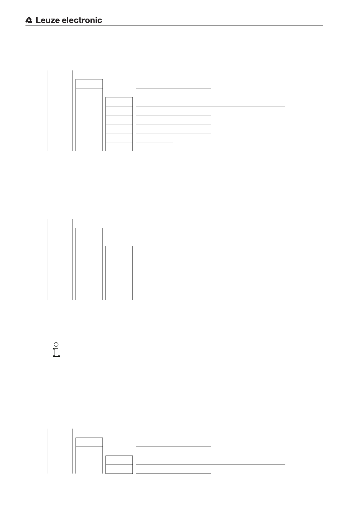
Starting up the device - Basic configuration
Configuration of pin 2 as PNP warning output
The following example shows the configuration of pin 2 as PNP warning output.
Level 0 Level 1 Level 2 Description
Digital IOs
IO Logic Positive PNP Negative NPN
IO Pin 2
IO Function Trigger input Teach input Area output Warning output
Inversion Normal Inverted
Teach height Execute Exit
Area logic AND OR
Start beam (enter value)
End beam (enter value)
Select Digital IOs > IO Logic > Positive PNP.
Select Digital IOs > IO Pin 2 > IO Function > Warn Out.
Configuration of pin 2 as PNP trigger input
The following example shows the configuration of pin 2 as PNP trigger input.
Level 0 Level 1 Level 2 Description
Digital IOs
IO Logic Positive PNP Negative NPN
IO Pin 2
IO Function Trigger input Teach input Area output Warning output
Inversion Normal Inverted
Teach height Execute Exit
Area logic AND OR
Start beam (enter value)
End beam (enter value)
Select Digital IOs > IO Logic > Positive PNP.
Select Digital IOs > IO Pin 2 > IO Function > Trigger In.
Trigger input and output are only active if cascading (triggered operation) was activated via the
configuration interface or process interface.
A teach input is configured according to the same principle.
Select Digital IOs > IO Logic > Positive PNP.
Select Digital IOs > IO Pin 2 > IO Function > Teach input.
Configuration of pin 5 as PNP height area
The following example shows the configuration of pin 5 as PNP height area.
Level 0 Level 1 Level 2 Description
Digital IOs
IO Logic Positive PNP Negative NPN
IO Pin 5
IO Function Trigger input Teach input Area output Warning output
Inversion Normal Inverted
Leuze electronic CSL 710 51
Page 52

Level 0 Level 1 Level 2 Description
Teach height Execute Exit
Area logic AND OR
Start beam (enter value)
End beam (enter value)
Select Digital IOs > IO Logic > Positive PNP.
Select Digital IOs > IO pin 5 > Teach height > Execute.
The height area is automatically configured as an area output.
IO Function > Area Out must also be selected.
8.5.2 Inversion of the switching behavior (light/dark switching)
Light/dark switching is configured with this configuration.
For all digital process interfaces, the configuration can also be performed via the interface (see
chapter 9) or via the
Sensor Studio
configuration software (see chapter 11).
Starting up the device - Basic configuration
The following example shows how the switching output is switched from light switching (normal) to dark
switching (inverted).
The structure of the configuration in the receiver control panel menu is as follows:
Level 0 Level 1 Level 2 Description
Digital IOs
IO Logic Positive PNP Negative NPN
IO Pin 2
Select Digital IOs > IO Pin 2 > Inversion > Inverted.
8.5.3 Defining the filter depth
The filter depth is used to specify that an evaluation of the measurement values occurs only once the beam
states are stable over multiple measurement cycles.
Example: with a filter depth of “5”, five measurement cycles must be consistent before an evaluation is
performed. For further information, see also the description of interference suppression (see chapter 4.8).
IO Function Trigger input Teach input Area output Warning output
Inversion Normal Inverted
Teach height Execute Exit
Area logic AND OR
Start beam (enter value)
End beam (enter value)
For all digital process interfaces, the configuration can also be performed via the interface (see
chapter 9) or via the
Sensor Studio
configuration software (see chapter 11).
When configuring the filter depth, you can enter values of up to 255. Values above 255 (to 299)
are not accepted and must be entered again.
The structure of the configuration in the receiver control panel menu is as follows:
Leuze electronic CSL 710 52
Page 53

Level 0 Level 1 Level 2 Description
Main Settings
Commands Teach Reset Factory settings
Operational setting
Select Main Settings > Operational Settings > Filter Depth.
8.5.4 Defining the display properties
With these configurations for the display, the brightness and a time unit for darkening the display are
defined.
Visibility:
• Off: no display; the display remains dark until a button is pressed.
• Dark: text is only slightly visible.
• Normal: text is visible with good contrast.
• Bright: text appears very bright.
• Dynamic: The display darkens gradually over the number of seconds configured under Time Unit (s).
During this time span, the display passes through all levels, from bright to off.
Filter Depth (enter value)
min = 1
max = 255
Starting up the device - Basic configuration
After approx. 5 minutes without button actuation, configuration mode is exited and the display
changes to the previous mode.
When configuring the Visibility in the dark, normal and bright modes, the display is completely
inverted after approx. 15 minutes to prevent the LEDs from burning in.
When configuring the Time Unit (s), you can enter values of up to 240 seconds. Values above
240 (to 299) are not accepted and must be entered again.
The structure of these configurations in the receiver control panel menu is as follows:
Level 0 Level 1 Level 2 Description
Display
Language English German French Italian Spanish
Operating
mode
Visibility Off Dark Normal Bright Dynamic
Time Unit (s) (enter value)
Process mode Alignment
min = 1
max = 240
Select Display > Visibility.
Select Display > Time Unit (s).
8.5.5 Changing the language
The system language can be configured with this configuration.
The structure of the configuration in the receiver control panel menu is as follows:
Leuze electronic CSL 710 53
Page 54
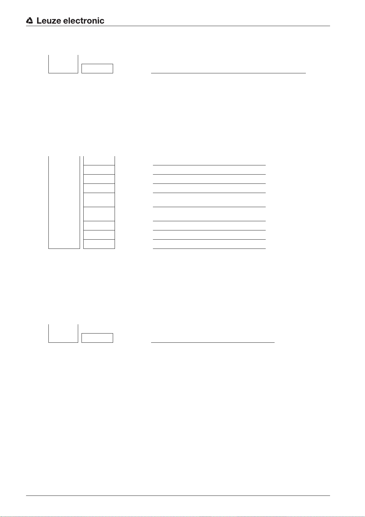
Level 0 Level 1 Level 2 Description
Display
Language English German French Italian Spanish
Select Display > Language.
8.5.6 Product information
With this configuration, you can read out product data (part number, type designation and other production-specific data) of the light curtain.
The structure of the configuration in the receiver control panel menu is as follows:
Level 0 Level 1 Level 2 Description
Information
Product name CSL710-R05-320.A/L-M12
Product ID Receiver part no. (e.g., 50119835)
Serial number Receiver serial number (e.g., 01436000288)
Tx.transmitterID
Tx.transmitterSN
FW version e.g., 01.61
HW version e.g., A001
Kx version e.g., P01.30e
Starting up the device - Basic configuration
Transmitter part no. (e.g., 50119407)
Transmitter serial no. (e.g., 01436000289)
Select Information.
8.5.7 Reset to factory settings
Factory settings can be restored with this configuration.
The structure of this menu item in the receiver control panel menu is as follows:
Level 0 Level 1 Level 2 Description
Main Settings
Commands Teach Reset Factory Settings
Select Main Settings > Command > Factory Settings.
Leuze electronic CSL 710 54
Page 55

Starting up the CSL 710 with IO-Link interface
9 Starting up the CSL 710 with IO-Link interface
The configuration of an IO-Link interface involves the following steps on the receiver control panel and the
IO-Link master module of the control-specific configuration software.
The configuration described in the following is not necessary if you only use the switching out-
puts.
General prerequisites:
• The light curtain has been mounted (see chapter 6) and connected (see chapter 7) correctly.
• The basic configuration has been performed (see chapter 8).
9.1 Defining IO-Link configurations on the receiver control panel
The parameters for the IO-Link interface are configured with the configuration of the bit rate. By changing
the bit rate, the light curtain receives a new IO-Link device ID and must be operated with the compatible
IO Device Description (IODD).
NOTICE
Changes take effect immediately!
The changes become effective directly (without restart), but are not automatically stored in non-volatile
memory.
The IODD file is supplied with the device and is available for download at www.leuze.com.
Factory settings
• Bit rate (COM2) = 38.4 kbit/s
The bit rate is configurable
• Process data length (PD length) and process data content are defined as follows (not configurable):
16 bit PD: vccc cccc aaaa aaaa
• v: PD validity or status information
• c: Measurement cycle counter
• a: Switching state of beam areas 8 … 1
The structure of this configuration in the receiver control panel menu is as follows:
Level 1 Level 2 Description
Commands Teach Reset Factory settings Exit
Operational setting Filter depth (enter value)
Beam mode Parallel Diagonal Crossed-beam
Function reserve High Medium Low
Blanking teach Not active Active
Power-Up teach Not active Active
Smoothing (enter value)
IO-Link Bit rate COM3: 230.4 kbit/s COM2: 38.4 kbit/s
Select Main Settings > IO-Link > Bit rate.
The bit rate is configured.
Other possible configuration steps are performed via the
Sensor Studio
configuration software (see
chapter 11).
Process mode is configured via the IO-Link master module of the control-specific software.
Leuze electronic CSL 710 55
Page 56

Starting up the CSL 710 with IO-Link interface
9.2 Defining configurations via the IO-Link master module of the PLC-specific software
General prerequisites:
• The light curtain has been mounted (see chapter 6) and connected (see chapter 7) correctly.
• The basic configuration has been performed (see chapter 8).
• IO-Link-specific basic configurations have been performed.
IO-Link bit rate selected
The IO Device Description (IODD) can be used both with connected light curtain for direct con-
figuration or without connected light curtain for creating device configurations.
The IODD files are supplied with the product. The IODD can also be downloaded from the
Internet at www.leuze.com.
Open the configuration software of the IO-Link master module.
Configure the following parameters:
- Beam mode (parallel-, diagonal-, crossed-beam)
- Blanking settings
- Teach settings
Perform a teach. This is possible via the receiver control panel or the control group in the IO-Link pro-
cess data (IO-Link object 2).
If necessary, configure additional parameter/process data (see chapter 9.3).
Save the configuration via the control group in the IO-Link process data (IO-Link object 2).
The IO-Link-specific configurations are performed and copied to the device. The device is prepared for
process mode.
9.3 Parameter/process data for IO-Link
The parameter data and process data are described in the IO-Link Device Description (IODD) file.
Details on the parameters and on the structure of the process data can be found in the .html document,
which is contained in the IODD zip file.
Sub-index access is not supported.
Overview
Group Group name
Group 1 System commands (see page 57)
Group 2 CSL 710 status information (see page 57)
Group 3 Device description (see page 57)
Group 4 General configurations (see page 59)
Group 5 Blanking settings (see page 59)
Group 6 Teach settings (see page 61)
Group 7 Digital IO pin N settings (N = 2, 5, 6, 7) (see page 61)
Group 8 Autosplitting (see page 62)
Group 9 Configuration for block evaluation of beam areas (see page 63)
Group 10 Evaluation functions (see page 64)
Leuze electronic CSL 710 56
Page 57
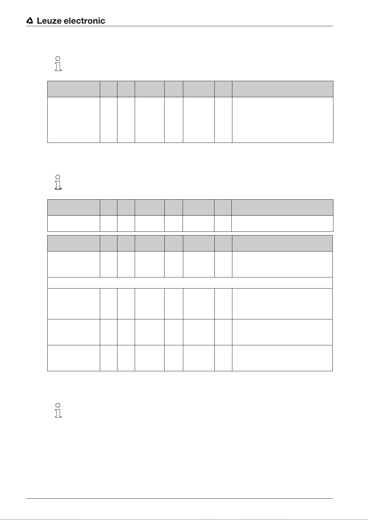
System commands (group 1)
The system commands trigger a direct action in the device.
Starting up the CSL 710 with IO-Link interface
Parameter Index Sub-
System command 2 unsigned 8 WO 128, 130, 162,
Data type Access Value range Default Explanation
index
163
128: Reset device
130: Factory reset
162: Perform teach
163: Save settings
Note:
Processing of the Save command takes up to
600 ms. During this time, no other data/telegrams
are accepted.
CSL 710 status information (group 2)
The status information consists of operating state information or error messages.
Parameter Index Sub-
CSL 710i status information
Parameter Index Sub-
Status of teach event 69 0 unsigned 8 RO 0, 1, 128 0 Status information on teach event
72 0 unsigned 16 RO Operating state information or error messages
Data type Access Value range Default Explanation
index
Data type Access Value range Default Explanation
index
0: Teach successful
1: Teach running
128: Teaching error
Alignment 70 0 record 32 bit,
Signal level of last beam 70 1
Signal level of first beam 70 2
isolated
access to
sub-index not
possible
unsigned 16 RO 0
(bit
offset
= 16)
unsigned 16 RO 0
(bit
offset
= 0)
Device description (group 3)
The device description specifies the device characteristics, e.g., beam spacing, the number of
physical/logical individual beams, the number of cascades (16 individual beams) in the device
and the cycle time.
RO Information on the signal level of the first and last
beam. The value changes depending on the
selected function reserve.
Leuze electronic CSL 710 57
Page 58

Starting up the CSL 710 with IO-Link interface
Parameter Index Sub-
Manufacturer name 16 0 string
Manufacturer text 17 0 string
Product name 18 0 string
Product ID 19 0 string
Product text 20 0 string
Serial number
Receiver
Hardware version 22 0 string
Firmware version 23 0 string
User-specific name 24 0 string
Device status 36 0 unsigned 8 R 0 … 4 Value: 0 device is OK
21 0 string
Data type Access Value range Default Explanation
index
32 bytes
64 bytes
64 bytes
20 bytes
64 bytes
16 bytes
20 bytes
20 bytes
32 bytes
RO Leuze electronic GmbH + Co. KG
RO Leuze electronic - the sensor people
RO Receiver type designation
RO Order number of the receiver (8-digit)
RO “Switching Light Curtain CSL 710”
RO Serial number of the receiver for unique product
RO
RO
RW *** Device designation defined by the user
identification
Value: 1 maintenance required
Value: 2 outside of specifications
Value: 3 function test
Value: 4 error
Receiver part no. 64 0 string
Transmitter product designation
Transmitter part no. 66 0 string
Transmitter serial
number
Device characteristics 68 0 record 80 bit,
Beam spacing 68 1
Number of physical individual beams
Number of configured
logical individual beams
65 0 string
67 0 string
68 2
68 3
20 bytes
64 bytes
20 bytes
16 bytes
isolated
access to
sub-index not
possible
unsigned 16 RO 5, 10, 20, 40 5 Distance between two adjacent optical individual
(bit
offset
= 64)
unsigned 16 RO 16
(bit
offset
= 48)
unsigned 16 RO 16 The number of logical individual beams is depen(bit
offset
= 32)
RO Order number of the receiver (8-digit)
RO Type designation
RO Order number of the transmitter (8-digit)
RO Transmitter serial number for unique product identi-
RO The device characteristics specify the beam spac-
fication
ing, the number of physical/logical individual
beams, the number of cascades (16 individual
beams) in the device and the cycle time.
beams.
dent on the selected operating mode.
The evaluation functions of the light curtain are calculated on the basis of the logical individual beams.
Number of optical cascades
Device cycle time 68 5
68 4
unsigned 16 RO 1 The light curtain is modular. 16 individual beams
(bit
offset
= 16)
unsigned 16 RO 1000 The device cycle time defines the duration of a
(bit
offset
= 0)
are always grouped into a cascade.
measurement cycle of the light curtain.
Leuze electronic CSL 710 58
Page 59

General configurations (group 4)
The type of scanning (parallel/diagonal/crossed beam), the minimum object diameter for evalu-
ation (smoothing), and filter depth and button lock on the receiver control panel are configured
under group 4 “General configurations”.
Starting up the CSL 710 with IO-Link interface
Parameter Index Sub-
General settings 71 0 record 32 bit,
Beam mode 71 1
Smoothing 71 3
Filter depth 74 2
Switching level of the
inputs/outputs
Button lock and display 78 0 unsigned 8 RW 0 … 1 0 Lock operational controls on the device.
77 0 unsigned 8 RW 0 … 1 1 0: Transistor, NPN
Data type Access Value range Default Explanation
index
isolated
access to
sub-index not
possible
unsigned 8 RW 0 … 2 0 0: Parallel-beam scanning
(bit
offset
= 24)
unsigned 8 RW 1 … 255 1 Smoothing:
(bit
offset
= 8)
unsigned 8 RW 1 … 255 1 The filter depth indicates the necessary number of
(bit
offset
= 16)
RW
1: Diagonal-beam scanning
2: Crossed-beam scanning
Less than i interrupted beams are ignored.
consistent beam states before the evaluation of the
measurement values. The filter depth corresponds
to the number of passes with interrupted beam so
that the result leads to switching.
1: Transistor, PNP
0: Enabled
1: Locked
Blanking settings (group 5)
Up to four beam areas can be deactivated. Deactivated beams can be assigned the logical
values 0, 1 or the value of the adjacent beam. With auto blanking activated, up to four beam
areas are automatically suppressed during teaching.
Activate auto blanking only during commissioning of the device to suppress distracting objects.
Deactivate auto blanking in process mode.
For details on this topic see chapter 10.3.
NOTICE
Perform teach after changing the blanking configuration!
Perform a teach after changing the blanking configuration.
A teach can be performed via the receiver control panel or via the teach command.
Leuze electronic CSL 710 59
Page 60

Starting up the CSL 710 with IO-Link interface
Parameter Index Sub-
Blanking settings 73 0 record
Number of auto-blanking
areas
Auto blanking (during
teaching)
Logical value for blanking
area 1
Start beam of blanking
area 1
End beam of blanking
area 1
73 1
73 2
73 3
73 4
73 5
Data type Access Value range Default Explanation
index
208 bit, iso-
lated access
to sub-index
not possible
unsigned 8 RW 0 … 4 0 Permissible number of auto-blanking areas
(bit
offset
= 200)
unsigned 8 RW 0 … 1 0 0: Not active (manual blanking area configuration)
(bit
offset
= 192)
unsigned 16 RW 0 … 4 0 0: No beams blanked
(bit
offset
= 176)
unsigned 16 RW 1 … 1774 1
(bit
offset
= 160)
unsigned 16 RW 1 … 1774 1
(bit
offset
= 160)
RW
0: 0 auto-blanking areas
1: 1 auto-blanking area
2: 2 auto-blanking areas
3: 3 auto-blanking areas
4: 4 auto-blanking areas
1: Active (automatic area configuration through
teach)
1: Logical value 0 for blanked beams
2: Logical value 1 for blanked beams
3: Logical value = same as adjacent beam with
lower beam number
4: Logical value = same as adjacent beam with
higher beam number
Logical value for blanking
area 2
Start beam of blanking
area 2
End beam of blanking
area 2
...... .... .... .. .. .. .......
...... .... .... .. .. .. .......
Logical value for blanking
area 4
Start beam of blanking
area 4
73 6
73 7
73 8
73 12
73 13
unsigned 16 RW 0 … 4 0 0: No beams blanked
(bit
offset
= 128)
unsigned 16 RW 1 … 1774 1
(bit
offset
= 112)
unsigned 16 RW 1 … 1774 1
(bit
offset
= 96)
unsigned 16 RW 0 … 4 0 0: No beams blanked
(bit
offset
= 32)
unsigned 16 RW 1 … 1774 1
(bit
offset
= 16)
1: Logical value 0 for blanked beams
2: Logical value 1 for blanked beams
3: Logical value = same as adjacent beam with
lower beam number
4: Logical value = same as adjacent beam with
higher beam number
1: Logical value 0 for blanked beams
2: Logical value 1 for blanked beams
3: Logical value = same as adjacent beam with
lower beam number
4: Logical value = same as adjacent beam with
higher beam number
End beam of blanking
area 4
73 14
unsigned 16 RW 1 … 1774 1
(bit
offset
= 0)
Leuze electronic CSL 710 60
Page 61
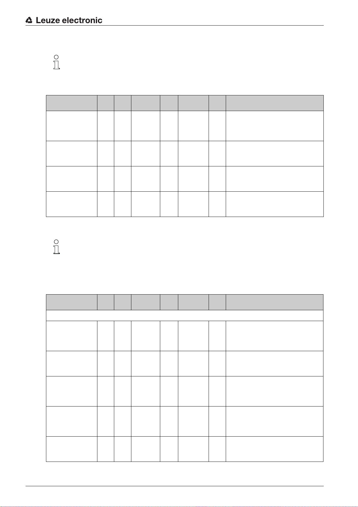
Teach settings (group 6)
In most applications, it is recommended that teach values be stored in non-volatile memory
(remanent).
Depending on the function reserve selected for the teach event, the sensitivity is higher or lower
(high function reserve = low sensitivity; low function reserve = high sensitivity).
Starting up the CSL 710 with IO-Link interface
Parameter Index Sub-
Teach settings 74 0 record 32 bit,
Type of storage for teach
values
Sensitivity adjustment for
teach event
Power-Up Teach 74 3
74 1
74 2
Data type Access Value range Default Explanation
index
isolated
access to
sub-index not
possible
unsigned 8 RW 0 … 1 0 0: Non-volatile storage of teach values
(bit
offset
= 16)
unsigned 8 RW 0 … 2 0 Sensitivity of the measurement system:
(bit
offset
= 8)
unsigned 8 RW 0 … 1 0 0: Deactivated
(bit
offset
= 0)
RW
Digital IO pin N settings (N = 2, 5, 6, 7) (group 7)
In this group, the inputs/outputs can be set to positive switching (PNP) or to negative switching
(NPN). The switching behavior applies the same for all inputs/outputs.
The inputs/outputs can be configured via this group: pin 2, pin 5, pin 6, pin 7.
1: Teach values stored only while voltage is ON
0: High function reserve (for stable operation)
1: Medium function reserve
2: Low function reserve
1: Activated - teach when applying operating voltage
In this group, the beam areas can be mapped to the switching outputs and assigned a time func-
tion.
Parameter Index Sub-
Configuration of pin 2
Digital IO Pin 2 Settings 80 0 record 32 bit,
Switching behavior 80 1
IO Function 80 2
Operating mode of the
time module
Time constant for
selected function
80 1
80 2
Data type Access Value range Default Explanation
index
isolated
access to
sub-index not
possible
unsigned 8 RW 0 … 1 0 0: Normal - light switching
(bit
offset
= 16)
unsigned 8 RW 0 … 4 2 0: Not active
(bit
offset
= 8)
unsigned 8 RW 0 … 4 0 0: Not active
(bit
offset
= 48)
unsigned 8 RW 0 … 65,000 0 Unit: ms
(bit
offset
= 32)
RW
1: Inverted - dark switching
1: Trigger input
2: Teach input
3: Switching output (area 1 … 8)
4: Warning output
1: Start-up delay
2: Switch-off delay
3: Pulse stretching
4: Pulse suppression
Leuze electronic CSL 710 61
Page 62
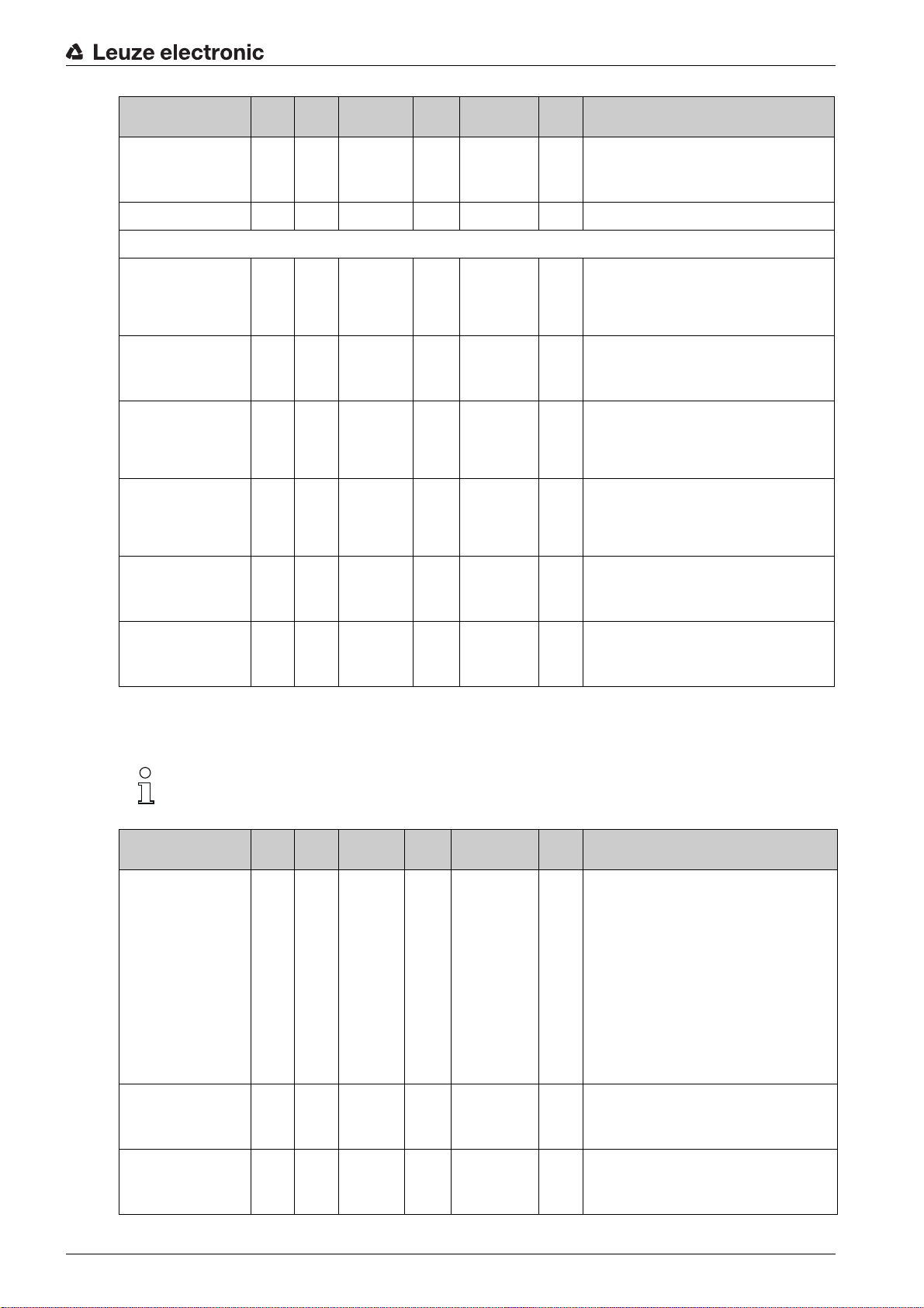
Starting up the CSL 710 with IO-Link interface
Parameter Index Sub-
Area mapping 8 … 1 80 6
...... .... .... .. .. .. .......
Configuration of pin 7
Digital IO Pin 7 Settings 83 0 record 32 bit,
Switching behavior 83 2
IO Function 83 2
Operating mode of the
time module
83 1
Data type Access Value range Default Explanation
index
unsigned 8 RW 0b000
(bit
offset
= 0)
isolated
access to
sub-index not
possible
unsigned 8 RW 0 … 1 0 0: Normal - light switching
(bit
offset
= 16)
unsigned 8 RW 0 … 4 4 0: Not active
(bit
offset
= 8)
unsigned 8 RW 0 … 4 0 0: Not active
(bit
offset
= 48)
RW
00001
1: Inverted - dark switching
1: Trigger input
2: Teach input
3: Switching output (area 1 … 8)
4: Warning output
1: Start-up delay
2: Switch-off delay
3: Pulse stretching
4: Pulse suppression
Time constant for
selected function
Area mapping 8 … 1 83 6
83 2
unsigned 16 RW 0 … 65,000 8 Unit: ms
(bit
offset
= 32)
unsigned 8 RW 0b000
(bit
offset
= 0)
Autosplitting (group 8)
In this group, it is possible to split all logical beams into areas of identical size. The fields of areas
1 … 8 are thereby automatically configured.
Parameter Index Sub-
Automatic splitting 76 0 unsigned 16RW 1 … 8
Data type Access Value range Default Explanation
index
1: (active: all
beams free - not
active: = one
beam interrupted)
257 … 264
2: (active: one
beam free - not
active: = all
beams interrupted)
00001
1:
Splitting of all logical beams into areas of identical
(active
size according to the number of areas set under
: all
“Number of areas”. The fields of areas 1 … 8 are
beams
thereby automatically configured.
free not
1: (active: all beams free –
active:
not active: ≥ one beam interrupted)
= one
1: One area
beam
…
inter-
8: Eight areas
rupted)
2: (active: one beam free –
not active: = all beams interrupted)
257: One area
…
264: Eight areas
Evaluation of the beams
in the area
Number of areas (evenly
split)
76 1
76 2
unsigned 8 RW 0 … 1 0 0: OR combination
(bit
offset
= 8)
unsigned 8 RW 1 … 8 1
(bit
offset
= 0)
1: AND combination
Leuze electronic CSL 710 62
Page 63
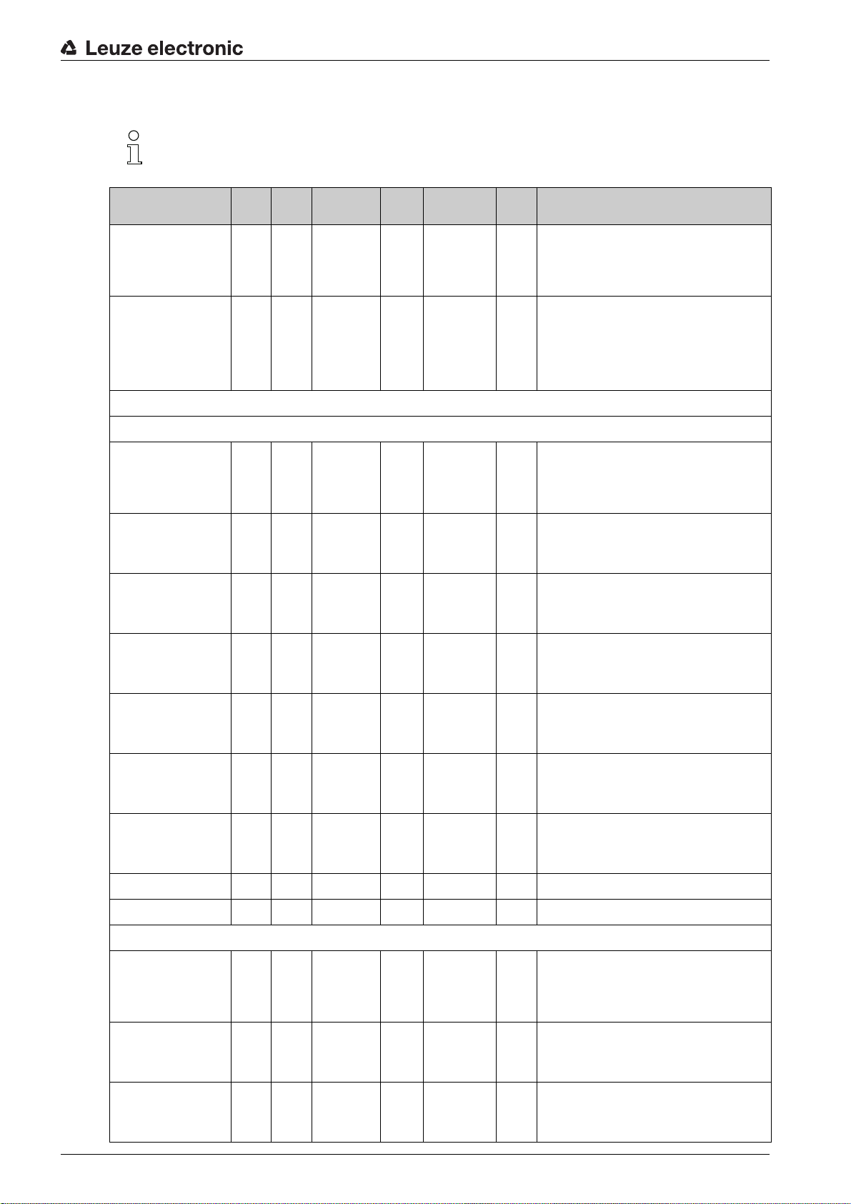
Configuration for block evaluation of beam areas (group 9)
In this group, a detailed area configuration can be displayed and a beam area configured for the
block evaluation.
Starting up the CSL 710 with IO-Link interface
Parameter Index Sub-
Teach height area 75 0 unsigned 8 RW 0 … 7 0 Active: all beams free
Display detailed area
configuration
Configuration of area 1
Configuration of area 01 90 1 record
Area 90 1
Active beam 90 1
77 0 unsigned 8 WO 1 … 8 Select the desired area (1 … 8) for which the con-
Data type Access Value range Default Explanation
index
Not active: at least one beam interrupted
1: Area 1
…
8: Area 8
figuration is to be edited in detail.
0: Area 01
1: Area 02
2: Area 03
…
7: Area 08
112 bit, iso-
lated access
to sub-index
not possible
unsigned 8 RW 0 … 1 0 0: Not active
(bit
offset
= 104)
unsigned 8 RW 0 … 1 0 0: Light switching (beam is active if light path is
(bit
offset
= 96)
RW Configuration of the area: definition of the status
conditions so that the area takes on a logical 1 or 0.
For diagonal- or crossed-beam mode, the numbers
of the logical beams are to be entered.
1: Active
free)
1: Dark switching (beam is active if light path is
interrupted)
Start beam of the area 90 1
End beam of the area 90 1
Number of active beams
for area ON
Number of active beams
for area OFF
...... .... .... .. .. .. .......
...... .... .... .. .. .. .......
Configuration of area 08
Configuration of area 08 97 8 record
Area 97 8
90 1
90 1
unsigned 8 RW 1 … 1774 1
(bit
offset
= 80)
unsigned 8 RW 1 … 1774 1
(bit
offset
= 64)
unsigned 16 RW 0 … 1774 0
(bit
offset
= 48)
unsigned 16 RW 0 … 1774 0
(bit
offset
= 32)
112 bit, iso-
lated access
to sub-index
not possible
unsigned 8 RW 0 … 1 0 0: Not active
(bit
offset
= 104)
RW Configuration of the area: definition of the status
conditions so that the area takes on a logical 1 or 0.
For diagonal- or crossed-beam mode, the numbers
of the logical beams are to be entered.
1: Active
Active beam 97 8
unsigned 8 RW 0 … 1 0 0: Light switching (beam is active if light path is
(bit
offset
= 96)
free)
1: Dark switching (beam is active if light path is
interrupted)
Leuze electronic CSL 710 63
Page 64

Starting up the CSL 710 with IO-Link interface
Parameter Index Sub-
Start beam of the area 97 8
End beam of the area 97 8
Number of active beams
for area ON
Number of active beams
for area OFF
97 8
97 8
index
(bit
offset
= 80)
(bit
offset
= 64)
(bit
offset
= 48)
(bit
offset
= 32)
Evaluation functions (group 10)
In this group, all evaluation functions can be configured.
The beam-stream values are updated in 1-second cycles.
Parameter Index Sub-
index
Data type Access Value range Default Explanation
unsigned 8 RW 1 … 1774 1
unsigned 16 RW 1 … 1774 1
unsigned 16 RW 1 … 1774 0
unsigned 16 RW 1 … 1774 0
Data type Access Value range Default Explanation
Evaluation function 40 0 unsigned 16 RO 16 bit process data (PD):
Beam-stream 100 0 array RO 8 bytes
Beam-stream 101 0 array RO 16 bytes
Beam-stream 102 0 array RO 32 bytes
Beam-stream 103 0 array RO 64 bytes
Beam-stream 104 0 array RO 128 bytes
Beam-stream 105 0 array RO 222 bytes
Beam-stream mask 106 0 array RO 222 bytes
vccc cccc aaaa aaaa
v: PD validity or status information
c: Measurement cycle counter
a: Switching state of areas 8 … 1
Bit N = 0: beam (N-1) assigned
Bit N = 1: beam (N-1) free
Bit N = 0: beam (N-1) is suppressed
Bit N = 1: beam (N-1) is active
Leuze electronic CSL 710 64
Page 65

10 Example configurations
10.1 Example configuration - Mapping of beams 1 … 32 to output pin 2
10.1.1 Configuration of area/output mapping (general)
The following table shows an example configuration for an area mapping to an output. In this example,
beams 1 … 32 are to be applied to output pin 2 on interface X1.
Map beams 1 … 32 to area 01.
Description / variables
Display detailed area configuration
Value: 0 = area 01
Configuration of area 01
Area
Value: 1 = active
Example configurations
Logical behavior of the area Value: 0
Start beam of the area
Value:1111
End beam of the area
Value: 32 32 32 32
Number of active beams for
area ON
Value: 32 32 1 1
Number of active beams for
area OFF
Value: 31 31 0 0
Switching behavior
Value: 0 = normal - light
switching (i.e., switching if
beams are free)
Switching behavior
Value: 1 = inverted - dark
switching (i.e., switching if
beams are interrupted)
Normal - light switching
(i.e., switching if beams are
free)
Output 1 if all beams are
free.
Output 0 if a beam is interrupted or if more than a
beam are interrupted.
Output 0 if all beams are
free.
Output 1 if one or more
beams are interrupted.
OR function
Value: 1
Inverted - dark switching
(i.e., switching if beams are
interrupted)
Output 0 if all beams are
free or 1 … 31 beams are
free.
Output 1 only if 32 beams
are interrupted.
Output 1 if all beams are
free or 1 … 31 beams are
free.
Output 0 only if 32 beams
are interrupted.
AND function
Value: 0
Normal - light switching
Output 1 if all beams are
free or as long as 1 … 31
beams are free.
Output 0 if 32 beams are
interrupted.
Output 0 if all beams are
free or as long as 1 … 31
beams are free.
Output 1 if 32 beams are
interrupted.
Value: 1
Inverted - dark switching
Output 0 if all beams are
free.
Output 1 as soon as a
beam is interrupted.
Output 1 if all beams are
free.
Output 0 as soon as a
beam is interrupted.
Configure pin 2 as area output.
Description / variables
Configuration of digital inputs/outputs
IO Function Value: 3 = Area output (area 1 … 8) The area output signals the logical states of beam
areas 1 … 8
Map pin 2 to configured area 1.
Digital Output 2 Settings
Area mapping 8 … 1
(OR combination)
0b00000001 Every area is displayed as a bit.
Possible additional area-to-pin configurations:
Map pin 2 to configured area 8.
Leuze electronic CSL 710 65
Page 66

Digital Output 2 Settings
Example configurations
Area mapping 8 … 1
(OR combination)
0b10000000
Map the configured areas 1 and 8 (OR-linked) to the corresponding switching output.
Digital Output 2 Settings
Area mapping 8 … 1
(OR combination)
0b10000001
10.2 Example configuration – Teach height area
The following tables show an example configuration for teaching two height areas and the assignment of
two outputs.
• Height area 01 is to be applied to output pin 2 of interface X1.
• Height area 02 is to be applied to output pin 5 of interface X1.
Teach height area 1.
A height area is automatically defined using an object.
When teaching a height area, all free beams are combined into one height area.
To define the entire beam area as a height area, a height area is taught without an object.
Description / variables
Configuration of beams in areas
Teach height area Value: area 1
Active: all beams free
Not active: one beam interrupted
All free beams are configured as area 1.
Configure pin 2 as area output.
Description / variables
Configuration of digital inputs/outputs
IO Function Value: 3 = Area output (area 1 … 8) The area output signals the logical states of beam
areas 1 … 8.
Map pin 2 to configured height area 1.
Description / variables
Configuration of pin 2
Area mapping 8 … 1
(OR combination)
0b00000001 Every area is displayed as a bit.
Teach height area 2.
Description / variables
Configuration of beams in areas
Teach height Value: area 2
Active: all beams free
Not active: one beam interrupted
All free beams are configured as area 2.
Configure pin 5 as area output.
Leuze electronic CSL 710 66
Page 67

Description / variables
Configuration of digital inputs/outputs
Example configurations
IO Function Value: 3 = Area output (area 1 … 8) The area output signals the logical states of beam
areas 1 … 8
Map pin 5 to configured height area 2.
Description / variables
Configuration of pin 5
Area mapping 8 … 1
(OR combination)
0b00000010
10.3 Example configuration - Activating and deactivating blanking areas
10.3.1 Configuration of blanking areas (general)
Perform the following settings to activate or deactivate blanking areas.
Example: automatic blanking of two areas during teaching
Blanking settings Parameter
Parameter
System commands Parameter
Number of auto blanking areas
Auto blanking (during teaching)
Teach command
: = 1 Execute teach command
: = 2 Two blanking areas permitted
: = 1 Automatic blanking-area configuration active
Example: Deactivation/resetting of auto blanking
Blanking settings Parameter
Parameter
Blanking settings Parameter
System commands Parameter
for blanking area 1
Parameter Function for blanking area/logical value
for blanking area 2:
Number of auto blanking areas
Auto blanking (during teaching)
Function for blanking area/logical value
:
Teach command
10.4 Example configuration – smoothing
10.4.1 Smoothing configuration (general)
Make the following settings for smoothing.
Example: Smoothing of four interrupted beams
Smoothing settings Parameter
beams are ignored
(see table 16.8
(see table 16.9
Smoothing -– less than i interrupted
:
: = 0 No blanking areas permitted
: = 0 Automatic blanking area configuration not active
= 0 No beams blanked
= 0 No beams blanked
: = 1 Execute teach command
= 4 Beams are taken into account in the evaluation once
there are four or more interrupted beams
Leuze electronic CSL 710 67
Page 68

Connecting to a PC – Sensor Studio
11 Connecting to a PC –
The
Sensor Studio
graphical user interface for the operation, configuration and diagnosis of sensors with IO-Link configuration
interface (IO-Link devices), independent of the selected process interface.
Each IO-Link device is described by a corresponding IO Device Description (IODD file). After importing the
IODD file into the configuration software, the IO-Link device connected to the IO-Link USB master can be
operated, configured and checked – conveniently and in multiple languages. An IO-Link device that is not
connected to the PC can be configured offline.
Configurations can be saved and reopened as projects for transferring back to the IO-Link device at a later
time.
Only use the
Leuze electronic.
The
lish, French, Italian and Spanish.
The FDT frame application of the
be supported in the IO-Link device DTM (Device Type Manager).
The
Sensor Studio
• Make individual configuration settings for the light curtain in the Device Type Manager (DTM).
• The individual DTM configurations of a project can be called up via the frame application of the Field
Device Tool (FDT).
• Communication DTM: IO-Link USB master
• Device DTM: IO-Link device/IODD for CSL 710
configuration software – in combination with an IO-Link USB master – provides a
Sensor Studio
configuration software is designed according to the FDT/DTM concept:
Sensor Studio
Sensor Studio
configuration software is offered in the following languages: German, Eng-
configuration software for products manufactured by
Sensor Studio
supports all languages; all languages may not
NOTICE
Configuration changes only via the control!
Always perform the configuration for process mode via the control and, if applicable, the interface.
In process mode, only the configuration conveyed via the control is active. The configuration changes
made via
control.
Procedure for the installation of the software and hardware:
Install the
Install the driver for the IO-Link USB master on the PC.
Connect the IO-Link USB master to the PC.
Connect the CSL 710 (IO-Link device) to the IO-Link USB master.
Install IO-Link device DTM with IODD file for CSL 710 in the
Sensor Studio
Sensor Studio
11.1 System requirements
To u se the
Sensor Studio
are only active in process mode if they were previously transmitted 1:1 to the
configuration software on the PC.
Sensor Studio
configuration software, you need a PC or laptop with the following specifications:
FDT frame.
Leuze electronic CSL 710 68
Page 69

Connecting to a PC – Sensor Studio
Table 11.1:
Operating system Windows 7
Computer
Graphics card DirectX 9 graphic device with WDDM 1.0 or higher driver
Additionally required
capacity for
Studio
device DTM
Administrator privileges on the PC are necessary for installing
System requirements for Sensor Studio
Windows 8
• Processor type: 1 GHz or higher
• USB interface
• CD-ROM drive
• Main memory
• 1 GB RAM (32-bit operating system)
• 2 GB RAM (64-bit operating system)
• Keyboard and mouse or touchpad
350 MB hard drive memory
Sensor
and IO-Link
64 MB main memory
installation
Sensor Studio
.
11.2 Installing
11.2.1 Installing the
NOTICE
First install the software!
Do not yet connect the IO-Link USB master to the PC.
First install the software.
Start the PC and insert the Sensor Studio & IO-Link USB Master data carrier.
The language selection menu starts automatically.
If the language selection menu does not start automatically, double-click the
Select a language for the interface text in the Installation Wizard and software.
The installation options are displayed.
Select Leuze electronic Sensor Studio and follow the instructions on the screen.
The Installation Wizard installs the software and places a shortcut on the desktop ( ).
Sensor Studio
The installation of the
Sensor Studio & IO-Link USB master.
For subsequent updates, you can fin d the most recent version of the
software on the Internet at www.leuze.com
If FDT frame software is already installed on your PC, you do not need the
lation.
You can install the communication DTM (IO-Link USB master) and the device DTM (IO-Link de-
vice CSL 710) in the existing FDT frame.
Sensor Studio
configuration software and IO-Link USB master
Sensor Studio
configuration software is done via supplied data carrier
Sensor Studio
FDT frame
start.exe
configuration
Sensor Studio
file.
instal-
11.2.2 Installing drivers for IO-Link USB master
Select the IO-Link USB Master installation option and follow the instruction on the screen.
Leuze electronic CSL 710 69
Page 70

The Installation Wizard installs the software and places a shortcut on the desktop ( ).
1
2
3
11.2.3 Connecting IO-Link USB master to the PC
The light curtain is connected to the PC via the IO-Link USB master (see table 16.8).
Connect the IO-Link USB master to the plug-in power supply unit or the mains supply.
Included in the delivery contents of the IO-Link USB master is a USB interconnection cable for
connecting the PC to the IO-Link USB master as well as a plug-in power supply unit and a short
description.
The mains supply of the IO-Link USB master via the plug-in power supply unit is only activated
if IO-Link USB master and PC are connected via the USB interconnection cable.
Connect the PC to the IO-Link USB master.
Connecting to a PC – Sensor Studio
1 IO-Link USB master
2 Plug-in power supply unit
3PC
Figure 11.1: PC connection via the IO-Link USB master
The wizard for searching for new hardware starts and installs the driver for the IO-Link USB master on
the PC.
11.2.4 Connect the IO-Link USB master to the light curtain
Prerequisites:
• IO-Link USB master and PC are connected via the USB interconnection cable.
• IO-Link USB master is connected to the mains supply with the plug-in power supply unit.
NOTICE
Connect the plug-in power supply unit for IO-Link USB master!
To connect a light curtain, the plug-in power supply unit must be connected to the IO-Link USB master
and the mains supply.
The voltage supply via the USB interface of the PC is permissible only for IO-devices with a current
consumption of up to 40 mA at 24 V.
Included in the delivery contents of the IO-Link USB master is a USB interconnection cable for
connecting the PC to the IO-Link USB master as well as a plug-in power supply unit and a short
description.
The voltage supply of the IO-Link USB master and the light curtain via the plug-in power supply
unit is only activated if IO-Link USB master and PC are connected via the USB interconnection
cable.
Leuze electronic CSL 710 70
Page 71

Connecting to a PC – Sensor Studio
2
31
4
Connect the IO-Link USB master to the receiver.
CSL 710 with IO-Link interface:
Connect the IO-Link USB master to interface X1 on the receiver with the connection cable (see
figure 0.1).
Connect the IO-Link USB master to interface X1 on the receiver with the connection cable (see
figure 11.2).
The connection cable is not included in the delivery contents and must be ordered separately if needed
(see chapter 16.4).
1 Receiver
2 IO-Link USB master
3 Plug-in power supply unit
4PC
Figure 11.2: CSL 710 connection to the IO-Link USB master
11.2.5 Installing the DTM and IODD
Prerequisites:
• The light curtain is connected to the PC via the IO-Link USB master.
• FDT frame and driver for IO-Link USB master are installed on the PC.
Select the IO-Link device DTM (User Interface) installation option and follow the instructions on the
screen.
The Installation Wizard installs the DTM and the IO Device Description (IODD) for the light curtain.
DTM and IODD for all IO-Link devices currently available from Leuze electronic are installed.
11.3 Starting the
Sensor Studio
Prerequisites:
• The light curtain has been mounted (see chapter 6) and connected (see chapter 7) correctly.
•The
Sensor Studio
configuration software is installed on the PC (see chapter 11.2 "Installing
Sensor Studio configuration software and IO-Link USB master").
• The light curtain is connected to the PC via the IO-Link USB master (see chapter 11.2 "Installing
Sensor Studio configuration software and IO-Link USB master").
Start the
Sensor Studio
configuration software by double-clicking the
The Mode selection of the Project Wizard is displayed automatically or under the File menu item.
configuration software
Sensor Studio
icon ( ).
Leuze electronic CSL 710 71
Page 72

Connecting to a PC – Sensor Studio
Select the Device selection without communication connection (offline) configuration mode and click on
[Next].
The Project Wizard displays the device selection list of the configurable devices.
Figure 11.3: Device selection for CSL 710i switching light curtain
Select the connected light curtain according to the configuration in the device selection and click on
[Next].
The device description in the device selection list contains the value for the bit rate configuration param-
eter for the respective light curtain. Factory setting on delivery: COM2
The device manager (DTM) of the connected light curtain starts with the offline view for the
configuration project.
Establish the online connection to the connected light curtain.
In the
Sensor Studio
In the
Sensor Studio
The IO-Link USB master synchronizes with the connected light curtain and the current configuration data
and process data are displayed in the device manager (DTM).
The menus of the
uration of the connected light curtain.
The user interface of the
The online help system provides information on the menu items and adjustment parameters. Select the
Help menu item in the menu [?].
Error message when [establishing connection with the device]
If the device selected in the device selection list of the
configuration (bit rate) of the connected light curtain, an error message is displayed.
Under IDENTIFICATION > CxL-7XX Device IDs, you will find a list with the assignment of the device IDs
displayed in the error message to the device description in the device selection list.
FDT frame, click on the [Establish connection with device] button ( ).
FDT frame, click on the [Online parameters] button ( ).
Sensor Studio
Sensor Studio
device manager (DTM) can be used to change or read out the config-
device manager (DTM) is largely self-explanatory.
Sensor Studio
Project Wizard does not match the
Sensor Studio
Leuze electronic CSL 710 72
Page 73

Connecting to a PC – Sensor Studio
Change the device selection in the device selection list according to the configuration (bit rate) of the
connected light curtain.
Alternatively, you can set the configuration (bit rate) of the light curtain in the receiver control panel cor-
responding to the device selection in the Device selection list.
In the
Sensor Studio
FDT frame, click on the [Establish connection with device] button ( ).
11.4 Short description of the
This chapter contains information and explanations on the individual menu items and adjustment parameters of the
light curtains.
The device managers (DTM) for light curtains of the
following main menus and functions:
•
IDENTIFICATION
•
CONFIGURATION
•
PROCESS
•
DIAGNOSIS
11.4.1 FDT frame menu
Sensor Studio
This chapter does not include a complete description of the
ware.
Complete information on the FDT frame menu and on the functions in the device manager (DTM)
can be found in the online help system.
(see chapter 11.4.2)
(see chapter 11.4.3)
(see chapter 11.4.4)
(see chapter 11.4.5)
The online help system displays information on the menu items and adjustment parameters for
each function. Select the Help menu item in the menu [?]
Sensor Studio
configuration software and the device manager (DTM) for CSL 710 switching
configuration software
Sensor Studio
Sensor Studio
configuration software have the
configuration soft-
11.4.2
11.4.3
You can find complete information on the FDT frame menu in the online help system. Select the
Help menu item in the menu [?].
IDENTIFICATION
•
Operating information
•
Technical description
•
CSL-7XX
list in the
The information is needed if an error message is displayed when connecting with the device.
CONFIGURATION
•
Save permanently
the device is de-energized.
With
Save permanently
the device.
function
: Information on operating the device manager (DTM)
: The available original operating instructions of the device in pdf format
: Table with the assignment of device IDs to the device description in the device selection
Sensor Studio
function
Project Wizard.
: Configuration changes via
, the configuration set via
Sensor Studio
Sensor Studio
are effective immediately but are lost if
is stored in non-volatile memory in
Leuze electronic CSL 710 73
Page 74
Connecting to a PC – Sensor Studio
NOTICE
Configuration for process mode only via the control!
Always perform the configuration for process mode via the control and, if applicable, the interface.
In process mode, only the configuration conveyed via the control is active. The configuration changes
made via
control.
•
Teach
can only be set via the
Sensor Studio
: The sensitivity of the teach event (see chapter 8.2 "Teaching the environmental conditions")
are only active in process mode if they were previously transmitted 1:1 to the
Sensor Studio
configuration software.
11.4.4
Upload device data set from device
•
device manager (DTM), e.g., to update the online view in
changed via the receiver control panel.
•
Upload device data set from device
• If the [Upload device data set from device] button ( ) is displayed in the device manager
(DTM), the
• If the [Synchronize with device] button ( ) is displayed in the device manager (DTM), the
Sensor Studio
If parameters are changed in the device manager (DTM) that affect other parameters (e.g., if
changing the beam mode causes the configured logical beams to change), the changes to these
parameters are configured in the device – but are not yet displayed in the
Click on the [Synchronize with device] button ( ) to synchronize the
the current configuration of the light curtain. Following successful synchronization, the [Upload
device data set from device] button ( ) is displayed in the device manager (DTM).
PROCESS
•The
• [Cyclical refresh] button ( ): Starts the cyclical acquisition of the process data, which are graphi-
function
Process
tain.
cally depicted under
display covers up to 300 seconds.
Sensor Studio
display is not consistent with the current configuration of the light curtain.
function offers graphical visualizations of the process data of the connected light cur-
Numerical display, Beam-stream display
display shows the current configuration of the light curtain.
( ): The configuration is uploaded from the device to the
( ) /
Sensor Studio
Synchronize with device
and Areas and outputs. Each graphical
after the configuration was
( ):
Sensor Studio
Sensor Studio
display.
display with
•
Beam-stream display
graphical cursor in the visualization, e.g., to evaluate the time difference between two events.
: Using the [Show or hide the graphical cursor] button ( ), you can move the
Leuze electronic CSL 710 74
Page 75

Connecting to a PC – Sensor Studio
Figure 11.4: Graphical visualization: Beam-stream display
11.4.5
11.4.6 Exiting
DIAGNOSIS
The
DIAGNOSIS
• Reset device, i.e., restart the connected light curtain
• Store configuration in non-volatile memory (see chapter 11.4.3)
After completing the configuration settings, close the
Exit the program via File > Exit.
Save the configuration settings as a configuration project on the PC.
You can open the configuration project again at later time via File > Open or via the
Wizard ( ).
function
function offers the following commands.
Sensor Studio
Sensor Studio
configuration software
Sensor Studio
Project
Leuze electronic CSL 710 75
Page 76

12 Troubleshooting
12.1 What to do in case of failure?
After switching on the light curtain, display elements (see chapter 3.4) assist in checking the proper function and troubleshooting.
In case of error, you can determine the error from the LED displays. With the error message you can determine the cause of the error and initiate measures to rectify it.
NOTICE
If the light curtain responds with an error display, you will often be able to eliminate the cause yourself!
Switch off the system and leave it switched off.
Analyze and eliminate the cause of the fault using the following table.
If you are unable to rectify the fault, contact the Leuze electronic branch responsible for you or call the
Leuze electronic customer service (see chapter 14 "Service and support").
12.2 Operating indicators of the LEDs
Table 12.1: Receiver LED displays - state and causes
LED green LED yellow State Possible cause
Troubleshooting
ON
(continuous
light)
OFF OFF Sensor not ready Interruption of the operating voltage;
OFF Flashing
Flashing synchronously
(3 Hz)
Flashing synchronously
(9 Hz)
Flashing alternately (9 Hz) System error No connection between transmitter
- Sensor ready
Missing function reserve Soiling of the lens covers
(15 Hz)
Teach running
Teach error Soiling of the lens covers
Light curtain in start-up phase
Misalignment of transmitter or
receiver
Operating range exceeded
Operating range exceeded
and receiver
Operating voltage too low
Receiver is not compatible with the
transmitter
Leuze electronic CSL 710 76
Page 77
Table 12.2: LED displays - causes and measures
Error Possible cause Measure
Troubleshooting
Teach error Soiling of the lens covers
Poor alignment of transmitter and
receiver
Function reserve too low Poor alignment of transmitter and
receiver
Soiling of the lens covers
Alignment signal too low Poor alignment of transmitter and
receiver
Soiling of the lens covers
Outputs are not active or
change their state without a
Configuration data is read or written
contour change in the measurement field
During teaching, the system checks whether the signals of all beams are within a certain corridor.
If there are considerable deviations in the signal strength, this results in a teaching error and is
indicated on the LEDs. The cause may be partial soiling of the lens cover.
Clean the lens cover on the receiver
and on the transmitter.
Check alignment.
Adjust alignment.
Test with shorter distance between
transmitter and receiver.
Clean the lens cover on the receiver
and on the transmitter.
Adjust alignment.
Test with shorter distance between
transmitter and receiver.
Clean the lens cover on the receiver
and on the transmitter.
End configuration communication.
Measure: clean the lens covers on the transmitter and receiver!
12.3 Error codes in the display
The following error messages can be output in the form of status codes in the device display.
Table 12.3: Normal mode
Status code Description
RxS 0x0100 CxL in normal mode, start-up phase still running
RxS 0x0180 CxL reconfigures itself after a configuration. Process data is invalid.
RxS 0x0190 The measurement system is not active (after a stop command or if the first trigger pulse
is missing).
RxS 0x0200 The “Leuze AutoControl ACON function” has detected soiling.
RxS 0x0300 Teach parameters have been changed (teaching must be done) or default values are
active.
RxS 0x0FFF CxL shuts down. Process data is invalid.
Leuze electronic CSL 710 77
Page 78
Table 12.4: Warnings
Error code Description Possible cause (s)
Troubleshooting
RxS 0x1000 Device in teach mode, no new
process data available
• Distance between transmitter and receiver too large
or too small
• Poor alignment
RxS 0x1100
RxS 0x1001
RxS 0x11xy
Teaching error
Trigger frequency too high
The device could not end
teach, no new process data
available
• Soiling
• Extraneous light, especially mutual interference
• Beams are interrupted, but blanking is deactivated
• The maximum number of blanking areas is not sufficient
• The number of beams to be blanked is greater than
RxS 0x111x Blanking error
or equal to the number of all logical beams
RxS 0x112x Error due to weak signal
Individual beams do not reach
the minimum reception level
RxS 0x113x Internal error
Device has reached the
power limit
Table 12.5: Errors (can be corrected)
Error code Description Measures
RxS 0x2000 No communication possible between transmitter and
Check cable.
receiver.
RxS 0x2001 Receiver/transmitter inconsistency.
Replace transmitter.
The receiver is not compatible with the transmitter.
RxS 0x2100 The supply voltage is not sufficient. Check voltage supply.
RxS 0x2200 EEPROM data corrupt. Reset device to factory set-
tings.
RxS 0x23xy Configuration error.
xy gives information on the type of configuration error.
Contact service (see
chapter 14).
Reset device to factory settings.
Check parameters and
parameter relation.
Leuze electronic CSL 710 78
Page 79
Table 12.6: Serious errors (cannot be corrected)
Error Description Measures
RxS 0x3000 Hardware error, no details available
RxS 0x3001 Hardware error, transmitter 9V supply
RxS 0x3002 Hardware error, transmitter 5V supply
Troubleshooting
RxS 0x3003 Hardware error, receiver 5V supply
RxS 0x3005 Hardware error, receiver cascade
No receiver cascade or different LED number of transmitter
and receiver
RxS 0x3006 Hardware error, transmitter
RxS 0x3007 Hardware error, inter-controller communication is inter-
rupted
RxS 0x3008 Hardware error, different number of diodes at transmitter
and receiver
RxS 0x3009
RxS 0x300A
RxS 0x3100
RxS 0x3101
Hardware error, no Rx cascades
Hardware error, no Tx cascades
Error in the factory settings. Can only be rectified by reprogramming the device firmware.
Return device following
consultation with Service
department (see
chapter 14)
Leuze electronic CSL 710 79
Page 80

13 Care, maintenance and disposal
13.1 Cleaning
In the event of dust build-up on the sensor:
Clean the sensor with a soft cloth; use a cleaning agent (commercially available glass cleaner) if nec-
essary.
NOTICE
Do not use aggressive cleaning agents!
Do not use aggressive cleaning agents such as thinner or acetone for cleaning the light curtains.
Use of improper cleaning agents can damage the lens cover.
13.2 Servicing
Usually, the light curtain does not require any maintenance by the operator.
Repairs to the device must only be carried out by the manufacturer.
For repairs, contact your responsible Leuze electronic subsidiary or Leuze electronic customer service
(see chapter 14).
Care, maintenance and disposal
13.2.1 Firmware update
A firmware update can only be performed by Leuze electronic customer service on-site or at the company
headquarters.
For firmware updates, contact your responsible Leuze electronic subsidiary or Leuze electronic cus-
tomer service (see chapter 14).
13.3 Disposing
For disposal observe the applicable national regulations regarding electronic components.
Leuze electronic CSL 710 80
Page 81

14 Service and support
Defective devices are repaired in our service center competently and quickly. Leuze electronic offers you
an extensive service packet to keep any necessary system downtimes to a minimum.
Our service center requires the following information:
• Customer number
• Part designation or part number
• Serial number or batch number
• Reason for return with description
24-hour on-call service at:
+49 (0) 7021 573-0
Service hotline:
+49 (0) 7021 573-123
Monday to Thursday, 8.00 a.m. to 5.00 p.m. (UTC+1)
Friday, 8.00 a.m. to 4.00 p.m. (UTC+1)
E-mail:
service.detect@leuze.de
Repair service and returns:
Procedure and Internet form can be found at
www.leuze.com/repair
Return address for repairs:
Service center
Leuze electronic GmbH + Co. KG
In der Braike 1
D-73277 Owen / Germany
Service and support
Leuze electronic CSL 710 81
Page 82

15 Technical data
15.1 General specifications
Table 15.1: Optical data
Light source LED (modulated light)
Wavelength 940 nm (infrared light)
Table 15.2: Measurement field data: Operating range limit and measurement field length of the
CSL 710i
Technical data
Beam spacing [mm]
Typ. op. range limit a) [m] Measurement field length b) [mm]
min. max. min. max.
5 0.1 4.5 160 2960
10 0.2 9.0 160 2880
20 0.2 9.0 150 2870
40 0.2 9.0 290 2850
a) Typ. operating range limit: min./max. attainable range without function reserve for parallel-beam scanning.
b) Measurement field lengths and beam spacings specified in fixed rasters, see ordering table.
Table 15.3: Operating ranges CSL 710
Beam spacing [mm] Operating range [m]
Parallel-beam
Operating range [m]
Diagonal-beam
Operating range [m]
Crossed-beam
min. max. min. max. min. max.
5 0.1 3.5 0.2 2.6 0.2 2.2
10 0.3 7.0 0.3 5.2 0.3 4.4
20 0.3 7.0 0.3 5.2 0.3 4.4
40 0.3 7.0 0.6 5.2 0.6 4.4
Table 15.4: CSL 710 profile and measurement field lengths
Measurement field
length B [mm]
with beam spacing A
5 mm
Measurement field
length B [mm]
with beam spacing A
10 mm
Measurement field
length B [mm]
with beam spacing A
20 mm
Measurement field
length B [mm]
with beam spacing A
40 mm
Profile length L
[mm]
160 160 150 - 168
240 - - - 248
320 320 310 290 328
400 - - - 408
480 480 470 - 488
560 - - - 568
Leuze electronic CSL 710 82
Page 83

Technical data
Measurement field
length B [mm]
with beam spacing A
5 mm
Measurement field
length B [mm]
with beam spacing A
10 mm
Measurement field
length B [mm]
with beam spacing A
20 mm
Measurement field
length B [mm]
with beam spacing A
40 mm
Profile length L
[mm]
640 640 630 610 648
720 - - - 728
800 800 790 808
880 - - - 888
960 960 950 930 968
1040 - - - 1048
1120 1120 1110 - 1128
1200 - - - 1208
1280 1280 1270 1250 1288
1360 - - - 1368
1440 1440 1430 - 1448
1520 - - - 1528
1600 1600 1590 1570 1608
1680 - - - 1688
1760 1760 1750 - 1768
1840 - - - 1848
1920 1920 1910 1890 1928
2000 - - - 2008
2080 2080 2070 - 2088
2160 - - - 2168
2240 2240 2230 2210 2248
2320 - - - 2328
2400 2400 2390 - 2408
2480 - - - 2488
2560 2560 2550 2530 2568
2640 - - - 2648
2720 2720 2710 - 2728
2800 - - - 2808
2880 2880 2870 2850 2888
2960 - - - 2968
Leuze electronic CSL 710 83
Page 84

Table 15.5: Data on the time behavior of the CSL 710
Technical data
Response time per beam
a)
30 µs
Readiness delay ≤ 1.5 s
a) Cycle time = number of beams x 0.03 ms + 0.4 ms. The minimum cycle time is 1 ms.
Table 15.6: Electrical data
Operating voltage U
B
Residual ripple ≤ 15% within the limits of U
18 … 30 VDC (incl. residual ripple)
B
Open-circuit current see table 15.7
Table 15.7: Open-circuit current CSL 710
Measurement field length
Current consumption [mA] (without load at switching output)
[mm]
24 VDC at UB 18 VDC at UB 30 VDC
at U
B
160 135 165 125
320 165 200 145
640 215 275 190
960 270 345 235
1440 350 455 300
1920 435 650 365
2880 600 780 500
Table 15.8: Interface data
Inputs/outputs 4 pins can be configured as input or output
Switching output current Max. 100 mA
Signal voltage active/not active ≥ 8 V / ≤ 2 V
Activation delay ≤ 1 ms
Input resistance Approx. 6 k Ω
Digital interfaces IO-Link (230.4 kbit/s; 38.4 kbit/s)
Table 15.9: Mechanical data
Housing Continuous-cast aluminum
Optics cover PMMA plastic
Connection technology M12 connectors
(8-pin / 5-pin)
Leuze electronic CSL 710 84
Page 85

Table 15.10: Environmental data
Ambient temperature (operation) -30 °C … +60 °C
Ambient temperature (storage) -40 °C … +70 °C
Protective circuit Transient protection
Polarity reversal protection
Short circuit protection for all outputs (provide external
protective circuit for inductive load for this purpose!)
Table 15.11: Certifications
Degree of protection IP 65
Safety class III
Certifications UL 508, CSA C22.2 No.14
Light source: exempt group (in acc. with EN 62471)
Standards applied IEC 60947-5-2
Electromagnetic compatibility IEC 61000-6-2 and EN 1000-6-4
Industrial interference emission
This is a Class A product. In a domestic environment, this
product may cause radio interference. In this case the
operator may be required to take appropriate measures.
Technical data
15.2 Timing
In principle, the individual beams are always processed sequentially for light curtains. The internal
controller starts transmitter 1 and then activates only the corresponding receiver 1 to measure the received
light power. If the measured value exceeds the switch-on threshold, this first beam is evaluated as an uninterrupted/free beam.
The time between activation of the transmitter and evaluation in the receiver is referred to as the response
time per beam.
In the CSL 710 the response time per beam is = 30 µs.
The total cycle time for the evaluation of all beams and transmission to the interface is calculated as
follows:
Cycle time = number of beams x response time per beam + constant
Example: cycle time = 192 beams x 0.03 ms + 0.4 ms = 6.16 ms
Table 15.12: Profile and measurement field lengths, cycle times for CSL 710
Measurement
field length B
[mm]
with beam spacing A
5 [mm]
The minimum cycle time is 1 ms, i.e., the cycle time is never less than 1 ms, even with very short
light curtains with a small number of beams.
Cycle time
[ms]
Measurement
field length B
[mm]
with beam spacing A
10 [mm]
Cycle time
[ms]
Measurement
field length B
[mm]
with beam spacing A
20 [mm]
Cycle time
[ms]
Measurement
field length B
[mm]
with beam spacing A
40 [mm]
Cycle time
[ms]
Profile length
L [mm]
160 1.36 160 1.00 150 1.00 - - 168
240 1.84 - - - - - - 248
320 2.32 320 1.36 310 1.00 290 1.00 328
400 2.8 - - - - - - 408
480 3.28 480 1.84 470 1.12 - - 488
Leuze electronic CSL 710 85
Page 86

Technical data
Measurement
field length B
[mm]
with beam spacing A
5 [mm]
560 3.76 - - - - - - 568
640 4.24 640 2.32 630 1.36 610 1.00 648
720 4.72 - - - - - - 728
800 5.2 800 2.8 790 808
880 5.68 - - - - - - 888
960 6.16 960 3.28 950 1.84 930 1.12 968
1040 6.64 - - - - - - 1048
1120 7.12 1120 3.76 1110 2.08 - - 1128
1200 7.6 - - - - - - 1208
1280 8.08 1280 4.24 1270 2.23 1250 1.36 1288
1360 8.56 - - - - - - 1368
1440 9.04 1440 4.72 1430 2.56 - - 1448
1520 9.52 - - - - - - 1528
Cycle time
[ms]
Measurement
field length B
[mm]
with beam spacing A
10 [mm]
Cycle time
[ms]
Measurement
field length B
[mm]
with beam spacing A
20 [mm]
Cycle time
[ms]
Measurement
field length B
[mm]
with beam spacing A
40 [mm]
Cycle time
[ms]
Profile length
L [mm]
1600 10.0 1600 5.2 1590 2.8 1570 1.6 1608
1680 10.48 - - - - - - 1688
1760 10.96 1760 5.68 1750 3.04 - - 1768
1840 11.44 - - - - - - 1848
1920 11.92 1920 6.16 1910 3.28 1890 1.84 1928
2000 12.4 - - - - - - 2008
2080 12.88 2080 6.64 2070 3.52 - - 2088
2160 13.36 - - - - - - 2168
2240 13.84 2240 7.12 2230 3.76 2210 2.08 2248
2320 14.32 - - - - - - 2328
2400 14.8 2400 7.6 2390 4.0 - - 2408
2480 15.28 - - - - - - 2488
2560 15.76 2560 8.08 2550 4.24 2530 2.32 2568
2640 16.24 - - - - - - 2648
2720 16.72 2720 8.56 2710 4.48 - - 2728
2800 17.2 - - - - - - 2808
2880 17.68 2880 9.04 2870 4.72 2850 2.56 2888
2960 18.16 - - - - - - 2968
Limits for detecting objects
The detection of objects and the evaluation of the data depend on the following factors:
• Beam resolution and cycle time of the light curtain
• Movement speed of the objects
• Transmission rate of the data bytes
• Cycle time of the PLC
Leuze electronic CSL 710 86
Page 87

Technical data
v
max
L10mm–tz=
L
min
vtz10m m+=
Minimum object diameter for detection perpendicular to beam plane
For a moving object, the cycle time of the light curtain must be shorter than the period of time that the object
to be detected is located in the beam plane.
For an object that moves vertically to the beam plane, the following apply:
v
[m/s] = Maximum object speed
max
L [m] = Length of the object in the direction of movement
t
[s] = Cycle time of the light curtain
z
or
L
[m] = Length of the object in the direction of movement (minimum length)
min
v [m/s] = Object speed
[s] = Cycle time of the light curtain
t
z
NOTICE
Minimum length of the gap between two successive objects!
The gap between two successive objects must be greater than the minimum object diameter.
15.3 Minimum object diameter for stationary objects
The minimum object diameter of a stationary object is determined by the beam spacing and optic diameter.
Minimum object diameter for “parallel”-beam mode:
The minimum object diameter depends on the beam spacing because objects also need to be reliably
detected in the transition area between two beams.
Beam spacing Minimum object diameter
5 mm Beam spacing + 5 mm = 10 mm
10 mm / 20 mm / 40 mm Beam spacing + 10 mm = 20 mm / 30 mm / 50 mm
NOTICE
Minimum object diameter for “crossed beam” mode!
In “crossed beam” mode, the object diameter in the center area is reduced to 1/2 x beam spacing.
Leuze electronic CSL 710 87
Page 88

15.4 Dimensioned drawings
Technical data
all dimensions in mm
A Beam spacing (see chapter 15.1)
B Measurement field length
C PWR IN/digital IO and IO-Link interface
D Connection to transmitter - synchronization
E Connection to receiver - synchronization
F M6 thread
G Fastening groove
L Profile length (see table 15.12)
R Receiver
T Transmitter
Y Devices with beam spacing 5 mm: Y = 2.5 mm
Y Devices with beam spacing 10, 20, 40 mm: Y = 5 mm
Figure 15.1: CSL 710 with axial connector outlet
Leuze electronic CSL 710 88
Page 89

15.5 Dimensioned drawings: Accessories
73
61
6.2
6.2
R3.1
R10
R10
22
10
R3.1
10.8
4
25
12.1
4
R10
Technical data
12
12
R3.1
R6
30
R3.1
R10
39
R3.1
29
16
18.4
31.7
all dimensions in mm
Figure 15.2: BT-2L mounting bracket
all dimensions in mm
Figure 15.3: BT-2Z parallel bracket
Leuze electronic CSL 710 89
Page 90

Technical data
Ø6,2
Ø6,2
34
20
8,2
28,3
23,75
9,1
41,2
8
7
51
Ø18
Ø28
37
41,4
17,3
12,8
21,8
8,2
20
34
8
7
37
51
Ø18
Ø28
0,75
29,4
~26.5
11. 3
a
b
~40
~34
70
10
35
60
all dimensions in mm
Figure 15.4: BT-2R1 swivel mount (shown in two mounting views)
Figure 15.5: BT-2SSD and BT-2SSD-270 swiveling mounting
all dimensions in mm
brackets
40
26,5
270
34
7
6
235
35
11,3
Leuze electronic CSL 710 90
Page 91

Technical data
20
8
5
0
20,5
39
6
0
Ø 5,3 (2x)
Ø 5,3 (2x)
3
4
65
80
40
20
14
all dimensions in mm
Figure 15.6: BT-2SB10/BT-2SB10-S swiveling mounting brackets
all dimensions in mm
Figure 15.7: BT-2P40 clamp bracket
Leuze electronic CSL 710 91
Page 92
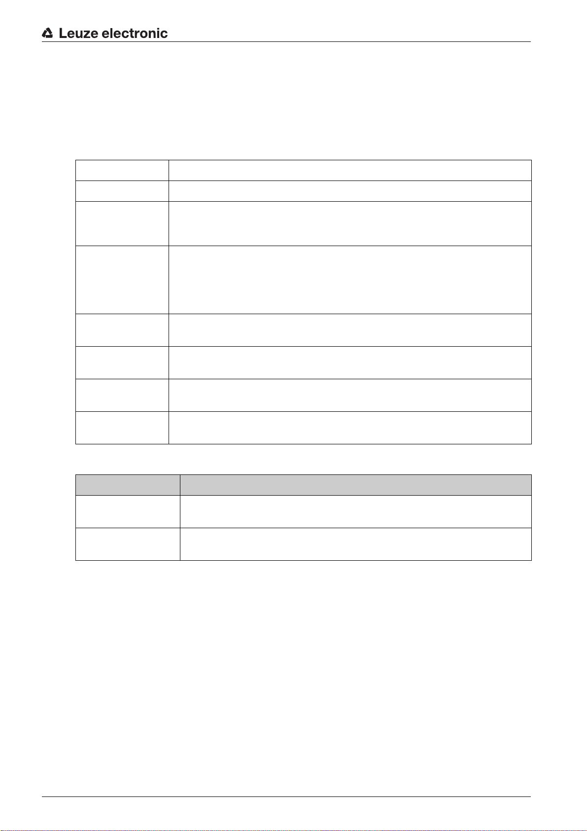
16 Ordering information and accessories
16.1 Nomenclature
Part designation:
CSLbbb- fss-xxxx.a/ii-eee
Table 16.1: Part number code
CSL Operating principle: switching light curtain
bbb Series: 710 for CSL 710
f Function classes:
T: Transmitter
R: Receiver
ss Beam spacing:
05: 5 mm
10: 10 mm
20: 20 mm
40: 40 mm
Ordering information and accessories
xxxx Measurement field length [mm], dependent on beam spacing:
For values see tables
a Equipment:
A: axial connector outlet
ii Interface:
L: IO-Link
eee Electrical connection:
M12: M12 connector
Table 16.2: Part descriptions, examples
Part designation Properties
CSL710-T20-2720.AM12
CSL710-R20-2720.A/
L-M12
CSL 710, transmitter, beam spacing 20 mm, measurement field length
2720 mm, axial connector outlet, M12 connector
CSL 710, receiver, beam spacing 20 mm, measurement field length 2720 mm,
axial connector outlet, IO-Link interface, M12 connector
Leuze electronic CSL 710 92
Page 93
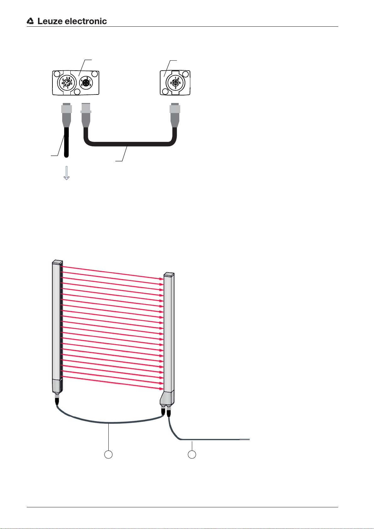
16.2 Accessories – CSL 710
PWR IN/OUT
X1 X
2
X3
1
2
3
4
1 Receiver (R)
2 Transmitter (T)
3 Connection cable (M12 socket, 8-pin)
4 Synchronization cable (M12 plug/socket, 5-pin)
Figure 16.1: Electrical connection – CSL 710
Ordering information and accessories
16.2.1 Connection to the switch cabinet (screw terminals)
Leuze electronic CSL 710 93
21
1 X2/X3 interconnection cable (transmitter – receiver synchronization), see table 16.4
2 X1 connection cable (IO-Link signal, digital IO, power for connection to control in switch cabinet),
see table 16.3
Figure 16.2: CSL 710 connection
Page 94

Ordering information and accessories
Table 16.3: X1 cable accessories – CSL 710
Part no. Part designation Description
X1 connection cables for CSL 710 (IO-Link signal, digital IO, power for connection to control in switch
cabinet); see figure 16.2
50104591 K-D M12A-8P-2m-PUR Connection cable, M12 socket, axial, 8-pin, length
2,000 mm, shielded PUR cable, open cable end
50104590 K-D M12A-8P-5m-PUR Connection cable, M12 socket, 8-pin, length
5,000 mm, shielded PUR cable, open cable end
50106882 K-D M12A-8P-10m-PUR Connection cable, M12 socket, 8-pin, length
10,000 mm, shielded PUR cable, open cable end
429178 CB-M12-8GF M12 socket, axial, 8-pin, user configurable
X1 cable (IO-Link/analog): core colors
• Pin1 = white
• Pin2 = brown
• Pin3 = green
• Pin4 = yellow
• Pin5 = gray
• Pin6 = pink
• Pin7 = blue
•Pin8 = red
The specified core colors apply only if the cables from Leuze electronic are used.
Table 16.4: X2/X3 cable accessories – CSL 710
Part no. Part designation Description
X2/X3 interconnection cables for CSL 710 (transmitter – receiver synchronization); see figure 16.2
50129779 KDS DN-M12-5A-M12-5A-P3-010 Interconnection cable, M12 plug/socket, axial,
5-pin, A-coded, length 1,000 mm, shielded, PUR
50129780 KDS DN-M12-5A-M12-5A-P3-020 Interconnection cable, M12 plug/socket, axial,
5-pin, A-coded, length 2,000 mm, shielded, PUR
50129781 KDS DN-M12-5A-M12-5A-P3-050 Interconnection cable, M12 plug/socket, axial,
5-pin, A-coded, length 5,000 mm, shielded, PUR
50129782 KDS DN-M12-5A-M12-5A-P3-100 Interconnection cable, M12 plug/socket, axial,
5-pin, A-coded, length 10,000 mm, shielded, PUR
50129783 KDS DN-M12-5A-M12-5A-P3-200 Interconnection cable, M12 plug/socket, axial,
5-pin, A-coded, length 20,000 mm, shielded, PUR
Leuze electronic CSL 710 94
Page 95

16.2.2 Connection to IO-Link master
21
Ordering information and accessories
1 X2/X3 interconnection cables (transmitter – receiver synchronization), see table 16.6
2 X1 connection cable (IO-Link, power to IO-Link master with M12 connections), see table 16.5
Figure 16.3: Connection to IO-Link master
Table 16.5: X1 cable accessories – CSL 710
Part no. Part designation Description
X1 interconnection cables for CSL 710 (IO-Link, power to IO-Link master with M12 connections); see
figure 16.3
50120999 K-DS M12A-8P-4P-2m-L-PUR Interconnection cable: M12 socket, 8-pin,
A-coded; shielded PUR cable, length 2,000 mm;
M12 plug, 4-pin, A-coded
50121000 K-DS M12A-8P-4P-5m-L-PUR Interconnection cable: M12 socket, 8-pin,
A-coded; shielded PUR cable, length 5,000 mm;
M12 plug, 4-pin, A-coded
Table 16.6: X2/X3 cable accessories – CSL 710
Part no. Part designation Description
X2/X3 interconnection cables for CSL 710 (transmitter – receiver synchronization); see figure 16.3
50129779 KDS DN-M12-5A-M12-5A-P3-010 Interconnection cable, M12 plug/socket, axial,
5-pin, A-coded, length 1,000 mm, shielded, PUR
50129780 KDS DN-M12-5A-M12-5A-P3-020 Interconnection cable, M12 plug/socket, axial,
5-pin, A-coded, length 2,000 mm, shielded, PUR
Leuze electronic CSL 710 95
Page 96

Part no. Part designation Description
50129781 KDS DN-M12-5A-M12-5A-P3-050 Interconnection cable, M12 plug/socket, axial,
50129782 KDS DN-M12-5A-M12-5A-P3-100 Interconnection cable, M12 plug/socket, axial,
50129783 KDS DN-M12-5A-M12-5A-P3-200 Interconnection cable, M12 plug/socket, axial,
16.3 Accessories – fastening technology
Table 16.7: Mounting technology accessories
Part no. Part designation Description
Mounting technology
429056 BT-2L L mounting bracket (angled), 2x
Ordering information and accessories
5-pin, A-coded, length 5,000 mm, shielded, PUR
5-pin, A-coded, length 10,000 mm, shielded, PUR
5-pin, A-coded, length 20,000 mm, shielded, PUR
429057 BT-2Z Z mounting bracket (parallel), 2x
429046 BT-2R1 360° swivel mount, 2x incl. 1 MLC cylinder
429058 BT-2SSD Swiveling mounting bracket with vibration damper,
8°, 70 mm long, 2x
429059 BT-4SSD Swiveling mounting bracket with vibration damper,
8°, 70 mm long, 4x
429049 BT-2SSD-270 Swiveling mounting bracket with vibration damper,
8°, 270 mm long, 2x
424422 BT-2SB10 Swiveling mounting bracket,
8°, 2x
424423 BT-2SB10-S Swiveling mounting bracket with vibration damper,
8°, 2x
424417 BT-2P40 Clamp bracket
425740 BT-10NC60 Sliding block with M6 thread, 10x
425741 BT-10NC64 Sliding block with M6 and M4 thread, 10x
425742 BT-10NC65 Sliding block with M6 and M5 thread, 10x
Leuze electronic CSL 710 96
Page 97
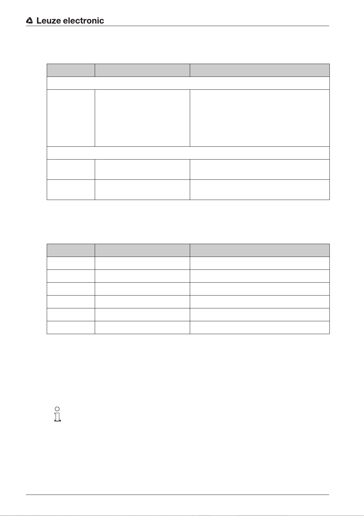
16.4 Accessories – PC connection
Table 16.8: Accessories - PC connection configuration
Part no. Part designation Description
IO-Link USB master V2.0
Ordering information and accessories
50121098 SET MD12-US2-
IL1.1 + accessories
Adapter cables for CSL 710 (IO-Link)
50120999 K-DS M12A-8P-4P-2m L-PUR Adapter cable: M12 socket, 8-pin, B-coded; PUR
50121000 K-DS M12A-8P-4P-5m L-PUR Adapter cable: M12 socket, 8-pin, B-coded; PUR
16.5 Accessories - Device columns
For devices with axial connector outlet only
Table 16.9: Accessories - Device columns
Part no. Part designation Description
549881 UDC-1000-S2-R Device column, U-shaped, profile height 1000 mm
IO-Link USB master V2.0
Plug-in power supply unit (24 V/24 W) with international adapters
High-speed USB 2.0 connection cable; USB A to
Mini-USB
Data carrier with software, drivers and documentation
cable, length 2,000 mm; M12 plug, 5-pin, B-coded
cable, length 5,000 mm; M12 plug, 5-pin, B-coded
549882 UDC-1300-S2-R Device column, U-shaped, profile height 1300 mm
549883 UDC-1600-S2-R Device column, U-shaped, profile height 1600 mm
549884 UDC-1900-S2-R Device column, U-shaped, profile height 1900 mm
549885 UDC-2500-S2-R Device column, U-shaped, profile height 2500 mm
549886 UDC-3100-S2-R Device column, U-shaped, profile height 3100 mm
16.6 Scope of delivery
• 1 transmitter incl. 2 sliding blocks (profile length from 2 m: 3 sliding blocks; profile length from 2.5 m:
4 sliding blocks)
• 1 receiver incl. 2 sliding blocks, (profile length from 2 m: 3 sliding blocks; profile length from 2.5 m: 4
sliding blocks)
• 1 set of operating instructions (PDF file on data carrier)
Connection and interconnection cables, mounting brackets, IO-Link USB master (incl.
Sensor Studio
rather be ordered separately.
configuration software), etc., are not included in the delivery contents but must
Leuze electronic CSL 710 97
Page 98

17 EC Declaration of Conformity
The switching light curtains of the CSL series have been developed and manufactured in accordance with
the applicable European standards and directives.
The manufacturer of the product, Leuze electronic GmbH + Co. KG in D-73277 Owen, possesses a certified quality assurance system in accordance with ISO 9001.
EC Declaration of Conformity
Leuze electronic CSL 710 98
 Loading...