

Page 1

EN 2015/05 50123881
We reserve the right to
Original operating instructions
make technical changes
CML 730i
Measuring light curtain
Page 2

Leuze electronic GmbH + Co. KG
In der Braike 1
D-73277 Owen / Germany
Phone: +49 7021 573-0
Fax: +49 7021 573-199
http://www.leuze.com
info@leuze.de
Leuze electronic CML 730i 2
Page 3

1 About this document . . . . . . . . . . . . . . . . . . . . . . . . . . . . . . . . . . . . . . . . . . . . . . 8
1.1 ≥sed symbols and signal words . . . . . . . . . . . . . . . . . . . . . . . . . . . . . . . . . . . . . . . . . . . . . 8
1.2 ≤erms and abbreviations . . . . . . . . . . . . . . . . . . . . . . . . . . . . . . . . . . . . . . . . . . . . . . . . . . . 8
2 Safety . . . . . . . . . . . . . . . . . . . . . . . . . . . . . . . . . . . . . . . . . . . . . . . . . . . . . . . . . 11
2.1 Intended use . . . . . . . . . . . . . . . . . . . . . . . . . . . . . . . . . . . . . . . . . . . . . . . . . . . . . . . . . . . 11
2.2 Foreseeable misuse . . . . . . . . . . . . . . . . . . . . . . . . . . . . . . . . . . . . . . . . . . . . . . . . . . . . . 11
2.3 Competent persons . . . . . . . . . . . . . . . . . . . . . . . . . . . . . . . . . . . . . . . . . . . . . . . . . . . . . . 12
2.4 Exemption of liability . . . . . . . . . . . . . . . . . . . . . . . . . . . . . . . . . . . . . . . . . . . . . . . . . . . . . 12
3 Device description . . . . . . . . . . . . . . . . . . . . . . . . . . . . . . . . . . . . . . . . . . . . . . . 13
3.1 General information . . . . . . . . . . . . . . . . . . . . . . . . . . . . . . . . . . . . . . . . . . . . . . . . . . . . . . 13
3.2 General performance characteristics. . . . . . . . . . . . . . . . . . . . . . . . . . . . . . . . . . . . . . . . . 13
3.3 Connection system . . . . . . . . . . . . . . . . . . . . . . . . . . . . . . . . . . . . . . . . . . . . . . . . . . . . . . 14
3.4 Display elements . . . . . . . . . . . . . . . . . . . . . . . . . . . . . . . . . . . . . . . . . . . . . . . . . . . . . . . . 14
3.4.1 Operation indicators on the receiver control panel . . . . . . . . . . . . . . . . . . . . . . . . . . . . . . 14
3.4.2 Display on the receiver control panel . . . . . . . . . . . . . . . . . . . . . . . . . . . . . . . . . . . . . . . . 15
3.4.3 Operating indicators on the transmitter . . . . . . . . . . . . . . . . . . . . . . . . . . . . . . . . . . . . . . . 17
3.5 Operating elements on the receiver control panel. . . . . . . . . . . . . . . . . . . . . . . . . . . . . . . 17
3.6 Menu structure of the receiver control panel . . . . . . . . . . . . . . . . . . . . . . . . . . . . . . . . . . . 18
3.7 Menu navigation on the receiver control panel . . . . . . . . . . . . . . . . . . . . . . . . . . . . . . . . . 20
3.7.1 Meaning of the display icons . . . . . . . . . . . . . . . . . . . . . . . . . . . . . . . . . . . . . . . . . . . . . . . 20
3.7.2 Level display . . . . . . . . . . . . . . . . . . . . . . . . . . . . . . . . . . . . . . . . . . . . . . . . . . . . . . . . . . . 20
3.7.3 Menu navigation . . . . . . . . . . . . . . . . . . . . . . . . . . . . . . . . . . . . . . . . . . . . . . . . . . . . . . . . 21
3.7.4 Editing value parameters. . . . . . . . . . . . . . . . . . . . . . . . . . . . . . . . . . . . . . . . . . . . . . . . . . 21
3.7.5 Editing selection parameters . . . . . . . . . . . . . . . . . . . . . . . . . . . . . . . . . . . . . . . . . . . . . . . 22
4 Functions . . . . . . . . . . . . . . . . . . . . . . . . . . . . . . . . . . . . . . . . . . . . . . . . . . . . . . 24
4.1 Beam modes . . . . . . . . . . . . . . . . . . . . . . . . . . . . . . . . . . . . . . . . . . . . . . . . . . . . . . . . . . . 24
4.1.1 Parallel. . . . . . . . . . . . . . . . . . . . . . . . . . . . . . . . . . . . . . . . . . . . . . . . . . . . . . . . . . . . . . . . 24
4.1.2 Diagonal . . . . . . . . . . . . . . . . . . . . . . . . . . . . . . . . . . . . . . . . . . . . . . . . . . . . . . . . . . . . . . 24
4.1.3 Crossed-beam . . . . . . . . . . . . . . . . . . . . . . . . . . . . . . . . . . . . . . . . . . . . . . . . . . . . . . . . . . 25
4.2 Measurement beam sequence . . . . . . . . . . . . . . . . . . . . . . . . . . . . . . . . . . . . . . . . . . . . . 26
4.3 Beam-stream . . . . . . . . . . . . . . . . . . . . . . . . . . . . . . . . . . . . . . . . . . . . . . . . . . . . . . . . . . . 27
4.4 Evaluation functions . . . . . . . . . . . . . . . . . . . . . . . . . . . . . . . . . . . . . . . . . . . . . . . . . . . . . 28
4.5 Hold function . . . . . . . . . . . . . . . . . . . . . . . . . . . . . . . . . . . . . . . . . . . . . . . . . . . . . . . . . . . 28
4.6 Blanking. . . . . . . . . . . . . . . . . . . . . . . . . . . . . . . . . . . . . . . . . . . . . . . . . . . . . . . . . . . . . . . 28
4.7 Power-≥p ≤each . . . . . . . . . . . . . . . . . . . . . . . . . . . . . . . . . . . . . . . . . . . . . . . . . . . . . . . . 30
4.8 Smoothing . . . . . . . . . . . . . . . . . . . . . . . . . . . . . . . . . . . . . . . . . . . . . . . . . . . . . . . . . . . . . 30
4.9 Cascading/triggering . . . . . . . . . . . . . . . . . . . . . . . . . . . . . . . . . . . . . . . . . . . . . . . . . . . . . 32
4.9.1 External triggering . . . . . . . . . . . . . . . . . . . . . . . . . . . . . . . . . . . . . . . . . . . . . . . . . . . . . . . 34
4.9.2 Internal triggering. . . . . . . . . . . . . . . . . . . . . . . . . . . . . . . . . . . . . . . . . . . . . . . . . . . . . . . . 35
4.10 Block evaluation of beam areas . . . . . . . . . . . . . . . . . . . . . . . . . . . . . . . . . . . . . . . . . . . . 36
4.10.1Defining beam area . . . . . . . . . . . . . . . . . . . . . . . . . . . . . . . . . . . . . . . . . . . . . . . . . . . . . . 36
4.10.2Autosplitting . . . . . . . . . . . . . . . . . . . . . . . . . . . . . . . . . . . . . . . . . . . . . . . . . . . . . . . . . . . . 36
4.10.3Mapping beam area to switching output . . . . . . . . . . . . . . . . . . . . . . . . . . . . . . . . . . . . . . 37
4.10.4≤each height area . . . . . . . . . . . . . . . . . . . . . . . . . . . . . . . . . . . . . . . . . . . . . . . . . . . . . . . 38
4.11 Switching outputs . . . . . . . . . . . . . . . . . . . . . . . . . . . . . . . . . . . . . . . . . . . . . . . . . . . . . . . 40
4.11.1Light/dark switching . . . . . . . . . . . . . . . . . . . . . . . . . . . . . . . . . . . . . . . . . . . . . . . . . . . . . . 40
4.11.2≤ime functions . . . . . . . . . . . . . . . . . . . . . . . . . . . . . . . . . . . . . . . . . . . . . . . . . . . . . . . . . . 40
4.12 Interference suppression (filter depth). . . . . . . . . . . . . . . . . . . . . . . . . . . . . . . . . . . . . . . . 40
5 Applications . . . . . . . . . . . . . . . . . . . . . . . . . . . . . . . . . . . . . . . . . . . . . . . . . . . . 41
Leuze electronic CML 730i 3
Page 4

5.1 Height measurement . . . . . . . . . . . . . . . . . . . . . . . . . . . . . . . . . . . . . . . . . . . . . . . . . . . . . 41
5.2 Object measurement . . . . . . . . . . . . . . . . . . . . . . . . . . . . . . . . . . . . . . . . . . . . . . . . . . . . . 42
5.3 Width measurement, orientation detection . . . . . . . . . . . . . . . . . . . . . . . . . . . . . . . . . . . . 43
5.4 Contour measurement. . . . . . . . . . . . . . . . . . . . . . . . . . . . . . . . . . . . . . . . . . . . . . . . . . . . 44
5.5 Gap control/gap measurement . . . . . . . . . . . . . . . . . . . . . . . . . . . . . . . . . . . . . . . . . . . . . 44
5.6 Hole recognition. . . . . . . . . . . . . . . . . . . . . . . . . . . . . . . . . . . . . . . . . . . . . . . . . . . . . . . . . 45
6 Mounting and installation . . . . . . . . . . . . . . . . . . . . . . . . . . . . . . . . . . . . . . . . . . 46
6.1 Mounting the light curtain . . . . . . . . . . . . . . . . . . . . . . . . . . . . . . . . . . . . . . . . . . . . . . . . . 46
6.2 Definition of directions of movement . . . . . . . . . . . . . . . . . . . . . . . . . . . . . . . . . . . . . . . . . 47
6.3 Fastening via sliding blocks. . . . . . . . . . . . . . . . . . . . . . . . . . . . . . . . . . . . . . . . . . . . . . . . 48
6.4 Fastening via swivel mount . . . . . . . . . . . . . . . . . . . . . . . . . . . . . . . . . . . . . . . . . . . . . . . . 48
6.5 Fastening via swiveling mounting brackets . . . . . . . . . . . . . . . . . . . . . . . . . . . . . . . . . . . . 49
7 Electrical connection . . . . . . . . . . . . . . . . . . . . . . . . . . . . . . . . . . . . . . . . . . . . . 50
7.1 Shielding and line lengths . . . . . . . . . . . . . . . . . . . . . . . . . . . . . . . . . . . . . . . . . . . . . . . . . 50
7.1.1 Shielding . . . . . . . . . . . . . . . . . . . . . . . . . . . . . . . . . . . . . . . . . . . . . . . . . . . . . . . . . . . . . . 50
7.1.2 Cable lengths for shielded cables . . . . . . . . . . . . . . . . . . . . . . . . . . . . . . . . . . . . . . . . . . . 52
7.2 Connection and interconnection cables. . . . . . . . . . . . . . . . . . . . . . . . . . . . . . . . . . . . . . . 53
7.3 Device connections . . . . . . . . . . . . . . . . . . . . . . . . . . . . . . . . . . . . . . . . . . . . . . . . . . . . . . 53
7.4 Digital inputs/outputs on connection X1 . . . . . . . . . . . . . . . . . . . . . . . . . . . . . . . . . . . . . . 53
7.5 Electrical connection – CML 700i with IO-Link/analog interface . . . . . . . . . . . . . . . . . . . . 54
7.5.1 X1 pin assignment – CML 700i with IO-Link interface . . . . . . . . . . . . . . . . . . . . . . . . . . . . 54
7.5.2 X1 pin assignment – CML 700i with analog interface . . . . . . . . . . . . . . . . . . . . . . . . . . . . 55
7.5.3 X2/X3 pin assignment – CML 700i with IO-Link/analog interface . . . . . . . . . . . . . . . . . . . 56
7.6 Electrical connection – CML 700i with fieldbus interface. . . . . . . . . . . . . . . . . . . . . . . . . . 56
7.6.1 Pin assignment – CML 700i with fieldbus interface . . . . . . . . . . . . . . . . . . . . . . . . . . . . . . 57
7.6.2 X2 pin assignment – CML 700i with CANopen interface. . . . . . . . . . . . . . . . . . . . . . . . . . 59
7.6.3 X2 pin assignment – CML 700i with Profibus or RS 485 Modbus interface . . . . . . . . . . . 59
7.7 Electrical supply. . . . . . . . . . . . . . . . . . . . . . . . . . . . . . . . . . . . . . . . . . . . . . . . . . . . . . . . . 60
8 Starting up the device - Basic configuration. . . . . . . . . . . . . . . . . . . . . . . . . . . . 61
8.1 Aligning transmitter and receiver . . . . . . . . . . . . . . . . . . . . . . . . . . . . . . . . . . . . . . . . . . . . 61
8.2 ≤eaching the environmental conditions . . . . . . . . . . . . . . . . . . . . . . . . . . . . . . . . . . . . . . . 63
8.2.1 ≤each via receiver control panel . . . . . . . . . . . . . . . . . . . . . . . . . . . . . . . . . . . . . . . . . . . . 63
8.2.2 ≤eaching via a control signal from the control . . . . . . . . . . . . . . . . . . . . . . . . . . . . . . . . . . 64
8.3 Check alignment . . . . . . . . . . . . . . . . . . . . . . . . . . . . . . . . . . . . . . . . . . . . . . . . . . . . . . . . 65
8.4 Setting the function reserve. . . . . . . . . . . . . . . . . . . . . . . . . . . . . . . . . . . . . . . . . . . . . . . . 66
8.5 Extended configurations on the receiver control panel menu . . . . . . . . . . . . . . . . . . . . . . 67
8.5.1 Define digital inputs/outputs . . . . . . . . . . . . . . . . . . . . . . . . . . . . . . . . . . . . . . . . . . . . . . . 67
8.5.2 Inversion of the switching behavior (light/dark switching) . . . . . . . . . . . . . . . . . . . . . . . . . 70
8.5.3 Defining the filter depth . . . . . . . . . . . . . . . . . . . . . . . . . . . . . . . . . . . . . . . . . . . . . . . . . . . 70
8.5.4 Defining the display properties . . . . . . . . . . . . . . . . . . . . . . . . . . . . . . . . . . . . . . . . . . . . . 70
8.5.5 Changing the language . . . . . . . . . . . . . . . . . . . . . . . . . . . . . . . . . . . . . . . . . . . . . . . . . . . 71
8.5.6 Product information . . . . . . . . . . . . . . . . . . . . . . . . . . . . . . . . . . . . . . . . . . . . . . . . . . . . . . 71
8.5.7 Reset to factory settings . . . . . . . . . . . . . . . . . . . . . . . . . . . . . . . . . . . . . . . . . . . . . . . . . . 72
9 Starting up the device - Analog output . . . . . . . . . . . . . . . . . . . . . . . . . . . . . . . . 73
9.1 Analog output configuration on the receiver control panel . . . . . . . . . . . . . . . . . . . . . . . . 73
9.2 Analog output configuration via the
9.3 Behavior of the analog output . . . . . . . . . . . . . . . . . . . . . . . . . . . . . . . . . . . . . . . . . . . . . . 74
Sensor Studio
configuration software . . . . . . . . . . . . 73
10 Starting up the device - IO-Link interface . . . . . . . . . . . . . . . . . . . . . . . . . . . . . . 76
Leuze electronic CML 730i 4
Page 5

10.1 Defining IO-Link device configurations on the receiver control panel . . . . . . . . . . . . . . . . 76
10.2 Defining configurations via the IO-Link master module of the PLC-specific software . . . . 76
10.3 Parameter/process data for IO-Link . . . . . . . . . . . . . . . . . . . . . . . . . . . . . . . . . . . . . . . . . 77
11 Starting up the device - CANopen interface . . . . . . . . . . . . . . . . . . . . . . . . . . . . 92
11.1 Defining the CANopen basic configuration on the receiver control panel . . . . . . . . . . . . . 92
11.2 Defining configurations via the PLC-specific software of the CANopen master . . . . . . . . 92
11.3 Parameter- / process data for CANopen . . . . . . . . . . . . . . . . . . . . . . . . . . . . . . . . . . . . . . 93
12 Starting up the device - Profibus interface . . . . . . . . . . . . . . . . . . . . . . . . . . . . 109
12.1 Defining the Profibus basic configuration on the receiver control panel . . . . . . . . . . . . . 109
12.2 Defining configurations via the PLC-specific software. . . . . . . . . . . . . . . . . . . . . . . . . . . 109
12.3 Parameter/process data for Profibus. . . . . . . . . . . . . . . . . . . . . . . . . . . . . . . . . . . . . . . . 110
12.3.1General information on Profibus . . . . . . . . . . . . . . . . . . . . . . . . . . . . . . . . . . . . . . . . . . . 110
12.3.2Configuration parameters or process data . . . . . . . . . . . . . . . . . . . . . . . . . . . . . . . . . . . 111
13 Starting up the device - RS 485 Modbus interface. . . . . . . . . . . . . . . . . . . . . . 120
13.1 Defining the RS 485 Modbus basic configuration on the receiver control panel . . . . . . . 120
13.2 Defining configurations via the RS 485 Modbus interface module of the PLC software . 120
13.2.1Modbus read access . . . . . . . . . . . . . . . . . . . . . . . . . . . . . . . . . . . . . . . . . . . . . . . . . . . . 121
13.2.2Modbus write access . . . . . . . . . . . . . . . . . . . . . . . . . . . . . . . . . . . . . . . . . . . . . . . . . . . . 122
13.2.3Error check (CRC calculation) . . . . . . . . . . . . . . . . . . . . . . . . . . . . . . . . . . . . . . . . . . . . . 122
13.2.4Defining configurations via the PLC-specific software. . . . . . . . . . . . . . . . . . . . . . . . . . . 124
13.3 Parameter/process data for RS 485 Modbus . . . . . . . . . . . . . . . . . . . . . . . . . . . . . . . . . 125
13.4 Autosend mode . . . . . . . . . . . . . . . . . . . . . . . . . . . . . . . . . . . . . . . . . . . . . . . . . . . . . . . . 135
14 Example configurations . . . . . . . . . . . . . . . . . . . . . . . . . . . . . . . . . . . . . . . . . . 137
14.1 Example configuration - Reading out 64 beams (beam-stream). . . . . . . . . . . . . . . . . . . 137
14.1.1Configuration of beam-stream process data via IO-Link interface . . . . . . . . . . . . . . . . . 137
14.1.2Configuration of beam-stream process data via CANopen interface . . . . . . . . . . . . . . . 137
14.1.3Configuration of beam-stream process data via Profibus interface . . . . . . . . . . . . . . . . . 137
14.1.4Configuration of beam-stream process data via RS 485 Modbus interface . . . . . . . . . . 138
14.2 Example configuration - Mapping of beams 1 … 32 to output pin 2 . . . . . . . . . . . . . . . . 138
14.2.1Configuration of area/output mapping (general) . . . . . . . . . . . . . . . . . . . . . . . . . . . . . . . 138
14.2.2Configuration of an area/output mapping via IO-Link interface . . . . . . . . . . . . . . . . . . . . 139
14.2.3Configuration of area/output mapping via CANopen interface . . . . . . . . . . . . . . . . . . . . 140
14.2.4Configuration of area/output mapping via Profibus interface. . . . . . . . . . . . . . . . . . . . . . 140
14.2.5Configuration of area/output mapping via RS 485 Modbus interface . . . . . . . . . . . . . . . 140
14.3 Example configuration - Hole recognition . . . . . . . . . . . . . . . . . . . . . . . . . . . . . . . . . . . . 141
14.3.1Configuration of hole recognition via IO-Link interface . . . . . . . . . . . . . . . . . . . . . . . . . . 141
14.3.2Configuration of hole recognition via CANopen interface . . . . . . . . . . . . . . . . . . . . . . . . 142
14.3.3Configuration of hole recognition via Profibus interface . . . . . . . . . . . . . . . . . . . . . . . . . 142
14.3.4Configuration of hole recognition via RS 485 Modbus interface . . . . . . . . . . . . . . . . . . . 142
14.4 Example configuration - Activating and deactivating blanking areas. . . . . . . . . . . . . . . . 143
14.4.1Configuration of blanking areas (general) . . . . . . . . . . . . . . . . . . . . . . . . . . . . . . . . . . . . 143
14.4.2Configuration of blanking areas via IO-Link interface . . . . . . . . . . . . . . . . . . . . . . . . . . . 143
14.4.3Configuration of blanking areas via CANopen interface . . . . . . . . . . . . . . . . . . . . . . . . . 144
14.4.4Configuration of blanking areas via Profibus interface . . . . . . . . . . . . . . . . . . . . . . . . . . 144
14.4.5Configuration of blanking areas via RS 485 Modbus interface . . . . . . . . . . . . . . . . . . . . 145
14.5 Example configuration – smoothing. . . . . . . . . . . . . . . . . . . . . . . . . . . . . . . . . . . . . . . . . 145
14.5.1Smoothing configuration (general) . . . . . . . . . . . . . . . . . . . . . . . . . . . . . . . . . . . . . . . . . 145
14.5.2Configuration of smoothing via IO-Link interface. . . . . . . . . . . . . . . . . . . . . . . . . . . . . . . 145
14.5.3Configuration of smoothing via CANopen interface. . . . . . . . . . . . . . . . . . . . . . . . . . . . . 145
14.5.4Configuration of smoothing via Profibus interface . . . . . . . . . . . . . . . . . . . . . . . . . . . . . . 146
14.5.5Configuration of smoothing via RS 485 Modbus interface . . . . . . . . . . . . . . . . . . . . . . . 146
Leuze electronic CML 730i 5
Page 6

14.6 Example configuration - Cascading. . . . . . . . . . . . . . . . . . . . . . . . . . . . . . . . . . . . . . . . . 146
14.6.1Configuration of a cascading arrangement (general) . . . . . . . . . . . . . . . . . . . . . . . . . . . 146
14.6.2Configuration of a cascading arrangement via IO-Link interface. . . . . . . . . . . . . . . . . . . 148
14.6.3Configuration of a cascading arrangement via CANopen interface. . . . . . . . . . . . . . . . . 150
14.6.4Configuration of a cascading arrangement via Profibus interface . . . . . . . . . . . . . . . . . . 152
14.6.5Configuration of a cascading arrangement via RS 485 Modbus interface . . . . . . . . . . . 154
15 Connecting to a PC –
15.1 System requirements. . . . . . . . . . . . . . . . . . . . . . . . . . . . . . . . . . . . . . . . . . . . . . . . . . . . 158
15.2 Installing
15.2.1Installing the
15.2.2Installing drivers for IO-Link ≥SB master . . . . . . . . . . . . . . . . . . . . . . . . . . . . . . . . . . . . 159
15.2.3Connecting IO-Link ≥SB master to the PC . . . . . . . . . . . . . . . . . . . . . . . . . . . . . . . . . . . 159
15.2.4Connect the IO-Link ≥SB master to the light curtain. . . . . . . . . . . . . . . . . . . . . . . . . . . . 159
15.2.5Installing the D≤M and IODD. . . . . . . . . . . . . . . . . . . . . . . . . . . . . . . . . . . . . . . . . . . . . . 161
15.3 Starting the
15.4 Short description of the
15.4.1FD≤ frame menu . . . . . . . . . . . . . . . . . . . . . . . . . . . . . . . . . . . . . . . . . . . . . . . . . . . . . . . 164
15.4.2
IDEN≤IFICA≤ION
15.4.3
CONFIG≥RA≤ION
15.4.4
PROCESS
15.4.5
DIAGNOSIS
15.4.6Exiting
Sensor Studio
Sensor Studio
function . . . . . . . . . . . . . . . . . . . . . . . . . . . . . . . . . . . . . . . . . . . . . . . . . . . . . 165
function . . . . . . . . . . . . . . . . . . . . . . . . . . . . . . . . . . . . . . . . . . . . . . . . . . . . 166
Sensor Studio
Sensor Studio
configuration software and IO-Link ≥SB master. . . . . . . . . . . . 158
Sensor Studio
function . . . . . . . . . . . . . . . . . . . . . . . . . . . . . . . . . . . . . . . . . . . . . . . 164
function. . . . . . . . . . . . . . . . . . . . . . . . . . . . . . . . . . . . . . . . . . . . . . . 164
FD≤ frame. . . . . . . . . . . . . . . . . . . . . . . . . . . . . . . . . . . . . . 158
. . . . . . . . . . . . . . . . . . . . . . . . . . . . . . . . . . . . . . . . . . . . . . . . 162
Sensor Studio
. . . . . . . . . . . . . . . . . . . . . . . . . . . . . . . . . . . . . . . . . . . . . . . . . . . 166
. . . . . . . . . . . . . . . . . . . . . . . . . . . . . . . . 157
configuration software . . . . . . . . . . . . . . . . . . . . 163
16 ≤roubleshooting . . . . . . . . . . . . . . . . . . . . . . . . . . . . . . . . . . . . . . . . . . . . . . . . 167
16.1 What to do in case of error? . . . . . . . . . . . . . . . . . . . . . . . . . . . . . . . . . . . . . . . . . . . . . . 167
16.2 Operating displays of the LEDs . . . . . . . . . . . . . . . . . . . . . . . . . . . . . . . . . . . . . . . . . . . . 167
16.3 Error codes in the display . . . . . . . . . . . . . . . . . . . . . . . . . . . . . . . . . . . . . . . . . . . . . . . . 168
17 Care, maintenance and disposal . . . . . . . . . . . . . . . . . . . . . . . . . . . . . . . . . . . 171
17.1 Cleaning . . . . . . . . . . . . . . . . . . . . . . . . . . . . . . . . . . . . . . . . . . . . . . . . . . . . . . . . . . . . . 171
17.2 Servicing . . . . . . . . . . . . . . . . . . . . . . . . . . . . . . . . . . . . . . . . . . . . . . . . . . . . . . . . . . . . . 171
17.2.1Firmware update . . . . . . . . . . . . . . . . . . . . . . . . . . . . . . . . . . . . . . . . . . . . . . . . . . . . . . . 171
17.3 Disposing. . . . . . . . . . . . . . . . . . . . . . . . . . . . . . . . . . . . . . . . . . . . . . . . . . . . . . . . . . . . . 171
18 Service and support . . . . . . . . . . . . . . . . . . . . . . . . . . . . . . . . . . . . . . . . . . . . . 172
19 ≤echnical data . . . . . . . . . . . . . . . . . . . . . . . . . . . . . . . . . . . . . . . . . . . . . . . . . 173
19.1 General specifications . . . . . . . . . . . . . . . . . . . . . . . . . . . . . . . . . . . . . . . . . . . . . . . . . . . 173
19.2 ≤iming . . . . . . . . . . . . . . . . . . . . . . . . . . . . . . . . . . . . . . . . . . . . . . . . . . . . . . . . . . . . . . . 176
19.3 Minimum object diameter for stationary objects . . . . . . . . . . . . . . . . . . . . . . . . . . . . . . . 178
19.4 Dimensional drawings . . . . . . . . . . . . . . . . . . . . . . . . . . . . . . . . . . . . . . . . . . . . . . . . . . . 179
19.5 Dimensional drawings: Accessories . . . . . . . . . . . . . . . . . . . . . . . . . . . . . . . . . . . . . . . . 180
20 Ordering information and accessories . . . . . . . . . . . . . . . . . . . . . . . . . . . . . . . 183
20.1 Nomenclature . . . . . . . . . . . . . . . . . . . . . . . . . . . . . . . . . . . . . . . . . . . . . . . . . . . . . . . . . 183
20.2 Accessories – CML 700i with IO-Link/analog interface . . . . . . . . . . . . . . . . . . . . . . . . . . 184
20.2.1IO-Link analog interface (connection in the switch cabinet: screw terminals) . . . . . . . . . 185
20.2.2IO-Link interface (connection to IO-Link master). . . . . . . . . . . . . . . . . . . . . . . . . . . . . . . 187
20.3 Accessories – CML 700i with CANopen, Profibus or RS 485 Modbus interface . . . . . . . 188
20.3.1CANopen interface . . . . . . . . . . . . . . . . . . . . . . . . . . . . . . . . . . . . . . . . . . . . . . . . . . . . . 188
20.3.2Profibus or RS 485 Modbus interface . . . . . . . . . . . . . . . . . . . . . . . . . . . . . . . . . . . . . . . 191
20.3.3Profibus/RS 485 Modbus interface (alternative terminating resistor) . . . . . . . . . . . . . . . 194
20.3.4Profibus/RS 485 Modbus interface (configuration with subsequent slave) . . . . . . . . . . . 195
Leuze electronic CML 730i 6
Page 7

20.4 Accessories - fastening technology . . . . . . . . . . . . . . . . . . . . . . . . . . . . . . . . . . . . . . . . . 195
20.5 Accessories – PC connection . . . . . . . . . . . . . . . . . . . . . . . . . . . . . . . . . . . . . . . . . . . . . 196
20.6 Scope of delivery . . . . . . . . . . . . . . . . . . . . . . . . . . . . . . . . . . . . . . . . . . . . . . . . . . . . . . . 196
21 EC Declaration of Conformity. . . . . . . . . . . . . . . . . . . . . . . . . . . . . . . . . . . . . . 197
Leuze electronic CML 730i 7
Page 8
1 About this document
≤hese original operating instructions contain information regarding the proper use of the CML 700i
measuring light curtain series. It is included in the delivery contents.
1.1 ≥sed symbols and signal words
≤able 1.1: Warning symbols, signal words and symbols
Pay attention to passages marked with this symbol. Failure to observe the provided instructions could lead to personal injury or damage to equipment.
Signal word for property damage
NO≤ICE
Indicates dangers that may result in property damage if the measures for danger avoidance are not followed.
Symbol for tips
≤ext passages with this symbol provide you with further information.
About this document
≤able 1.2: Operating on the display
Main Settings
Digital IOs
1.2 ≤erms and abbreviations
≤able 1.3: ≤erms and abbreviations
D≤M (Device ≤ype Manager) Software device manager of the sensor
IO Input Output
First Beam) First beam
FB (
FIB (First Interrupted Beam) First interrupted beam
Symbols for action steps
≤ext passages with this symbol instruct you to perform actions.
Bold text
Indicates that this field is currently selected and appears highlighted in
the receiver display.
Normal text
Indicates that this field is not currently selected (is not highlighted in the
receiver display).
FNIB (First Not Interrupted Beam) First uninterrupted beam
Field Device ≤ool) Software frame for management of device managers (D≤M)
FD≤ (
LB (Last Beam) Last beam
LIB (Last Interrupted Beam) Last interrupted beam
Last Not Interrupted Beam) Last uninterrupted beam
LNIB (
≤IB (≤otal Interrupted Beams) Number of all interrupted beams
≤otal Not Interrupted Beams) Number of all uninterrupted beams (≤NIB = n - ≤IB)
≤NIB (
n Number of all logical beams of a light curtain; dependent on the
selected measurement field length and resolution as well as the
beam mode (parallel- / diagonal- / crossed-beam scanning)
EDS Electronic Data Sheet (EDS file for CANopen interface)
Description of the device for the control
Leuze electronic CML 730i 8
Page 9

About this document
GSD Device master data file (GSD file for Profibus interface)
Description of the device for the control
IODD IO Device Description (IODD file for IO-Link interface)
Description of the device for the control
Graphical ≥ser Interface) Graphical user interface
G≥I (
R≤≥ Remote ≤erminal ≥nit (serial RS 485 Modbus R≤≥ mode)
PLC Programmable Logic Control
(corresponds to Programmable Logic Controller (PLC))
Response time per beam Length of time for the evaluation of a beam
Resolution ≤he minimum size of an object that can be reliably detected.
With parallel-beam evaluation, the smallest object to be
detected corresponds to the sum of beam spacing and optic
diameter.
Delay before start-up Duration between the switching on of the supply voltage and
the start of operational readiness of the light curtain
Function reserve (sensitivity adjustment)
Ratio of the optical reception power set during the teach event
and the minimum light quantity required to switch the individual
beam. ≤his compensates for the light attenuation caused by
dirt, dust, smoke, humidity and vapor.
High function reserve = low sensitivity
Low function reserve = high sensitivity
Meas. field length Optical detection range between the first and last beam
Beam spacing Center-to-center spacing between two beams
Cycle time Sum of the response times of all beams of a light curtain plus
the duration of the internal evaluation.
Cycle time =
number of beams x response time per beam + evaluation time
Leuze electronic CML 730i 9
Page 10

1 ≤IB (Number of all interrupted beams)
1
6
3
2
2
5
4
2 ≤NIB (Number of all uninterrupted beams)
3 LIB (Last interrupted beam )
4 LNIB (Last uninterrupted beam)
5 FNIB (First uninterrupted beam)
6 FIB (First interrupted beam)
Figure 1.1: Definition of terms
About this document
Leuze electronic CML 730i 10
Page 11

2 Safety
≤his sensor was developed, manufactured and tested in line with the applicable safety standards. It corresponds to the state of the art.
2.1 Intended use
≤he device is designed as a measuring and object-detecting, configurable, multi-sensor unit.
Areas of application
≤he measuring light curtain is designed for the measurement and detection of objects for the following
areas of application in handling and warehousing systems, the packaging industry or a comparable environment:
• Height measurement
• Width measurement
• Contour measurement
• Orientation detection
CA≥≤ION
Observe intended use!
Only operate the device in accordance with its intended use.
≤he protection of personnel and the device cannot be guaranteed if the device is operated in a manner
not complying with its intended use.
Leuze electronic GmbH + Co. KG is not liable for damages caused by improper use.
Read the original operating instructions before commissioning the device.
Knowledge of the original operating instructions is an element of proper use.
Safety
NO≤ICE
Comply with conditions and regulations!
Observe the locally applicable legal regulations and the rules of the employer's liability insurance asso-
ciation.
2.2 Foreseeable misuse
Any use other than that defined under Intended use or which goes beyond that use is considered
improper use.
In particular, use of the device is not permitted in the following cases:
• Rooms with explosive atmospheres
• Circuits relevant to safety
• Operation for medical purposes
NO≤ICE
Do not modify or otherwise interfere with the device!
Do not carry out modifications or otherwise interfere with the device.
≤he device must not be tampered with and must not be changed in any way.
≤he device must not be opened. ≤here are no user-serviceable parts inside.
Repairs must only be performed by Leuze electronic GmbH + Co. KG.
Leuze electronic CML 730i 11
Page 12

2.3 Competent persons
Connection, mounting, commissioning and adjustment of the device must only be carried out by competent
persons.
Prerequisites for competent persons:
• ≤hey have a suitable technical education.
• ≤hey are familiar with the rules and regulations for occupational safety and safety at work.
• ≤hey are familiar with the original operating instructions of the device.
• ≤hey have been instructed by the responsible person on the mounting and operation of the device.
Certified electricians
Electrical work must be carried out by a certified electrician.
Due to their technical training, knowledge and experience as well as their familiarity with relevant stan-
dards and regulations, certified electricians are able to perform work on electrical systems and independently detect possible dangers.
In Germany, certified electricians must fulfill the requirements of accident-prevention regulations BGV A3
(e.g. electrician foreman). In other countries, there are respective regulations that must be observed.
2.4 Exemption of liability
Leuze electronic GmbH + Co. KG is not liable in the following cases:
Safety
• ≤he device is not being used properly.
• Reasonably foreseeable misuse is not taken into account.
• Mounting and electrical connection are not properly performed.
• Changes (e.g., constructional) are made to the device.
Leuze electronic CML 730i 12
Page 13

3 Device description
X2X3
3
2 41
X1
5 6
3.1 General information
≤he light curtains of the CML 700i series are designed as measuring and object-detecting, configurable,
multi-sensor units. Depending on the configuration and model, the devices are suitable for a variety of
tasks with various resolutions and can be integrated in different control environments.
≤he total system of the light curtain consists of a transmitter and a receiver, including the connection and
interconnection cables.
• ≤ransmitter and receiver are connected to one another via a synchronization cable.
• ≤he integrated control panel with indicators and operational controls for configuring the total system
is located on the receiver.
• ≤he shared power supply is provided via connection X1 on the receiver.
Device description
1 ≤ransmitter
2 Receiver
3 IO Logic with control panel
4 Control (PLC)
5 Synchronization cable
6 Connection cable for supply voltage and measurement data interface
Figure 3.1: ≤otal system in combination with a programmable logic control
3.2 General performance characteristics
≤he most important performance characteristics of the CML 730i series are:
• Operating range up to 8000 mm
• Measurement field length from 150 mm to 2960 mm
• Beam spacings of 5 mm, 10 mm, 20 mm, 40 mm
• Response time 10 µs per beam
• Beam modes: parallel, diagonal, crossed-beam
• Single-beam evaluation (beam-stream)
• Evaluation functions: ≤IB, ≤NIB, LIB, LNIB, FIB, FNIB, status of beam areas 1 … 32, status of the
digital inputs/outputs
• Local control panel with display
• Interfaces to the machine control:
• IO-Link:
4 digital inputs/outputs (configurable)
Leuze electronic CML 730i 13
Page 14

• CANopen, Profibus-DP, RS 485 Modbus:
1
2
2 digital inputs/outputs (configurable) plus IO-Link
• Analog:
2 analog current/voltage outputs plus IO-Link
2 digital inputs/outputs (configurable)
• Blanking of unnecessary beams
• Smoothing for interference suppression
• Cascading of multiple devices
• Block evaluation of beam areas
• Position / hole recognition with continuous web material
• Detection of transparent media
3.3 Connection system
≤he transmitter and receiver feature an M12 connector with the following number of pins:
Device type Designation on device Plug/socket
Receiver X1 M12 plug (8-pin)
Receiver X2 M12 socket (5-pin)
Device description
≤ransmitter X3 M12 plug (5-pin)
3.4 Display elements
≤he display elements show the device status in operation and provide support during commissioning and
error analysis.
Located on the receiver is a control panel with the following display elements:
•two LEDs
• one OLED display (Organic Light-Emitting Diode), two-line
Located on the transmitter is the following display element:
•one LED
3.4.1 Operation indicators on the receiver control panel
≤wo function indicator LEDs are located on the receiver control panel.
1 LED1, green
2 LED2, yellow
Figure 3.2: LED indicators on the receiver
Leuze electronic CML 730i 14
Page 15
≤able 3.1: Meaning of the LEDs on the receiver
12
3
LED Color State Description
Device description
1 Green ON (continuous
light)
Flashing see chapter 16.2
OFF Sensor not ready
2 Yellow ON (continuous
light)
Flashing see chapter 16.2
OFF At least one beam interrupted (object detected)
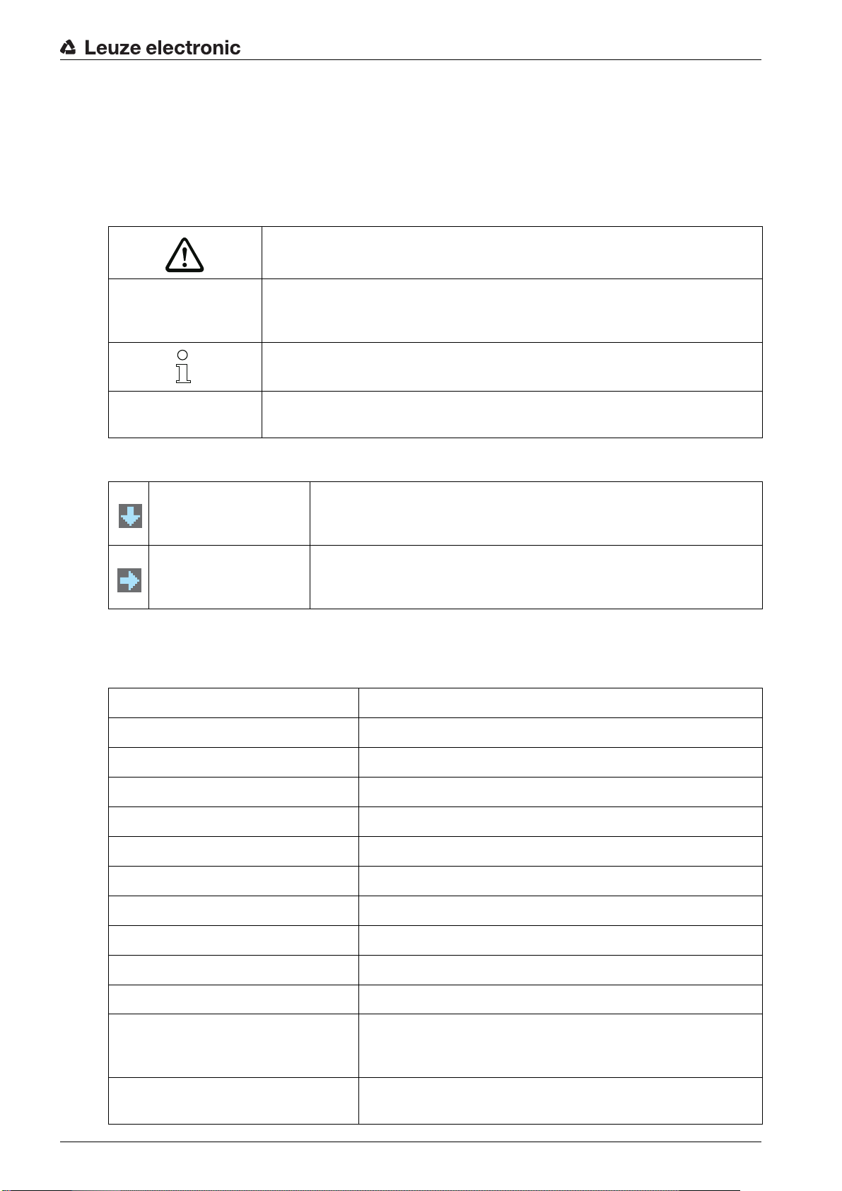
3.4.2 Display on the receiver control panel
Located on the receiver is an OLED display which serves as a function indicator.
Light curtain ready (normal mode)
All active beams are free - with function reserve
Figure 3.3: OLED display on the receiver
≤he type of display on the OLED display is different for the following operating modes:
• Alignment mode
• Process mode
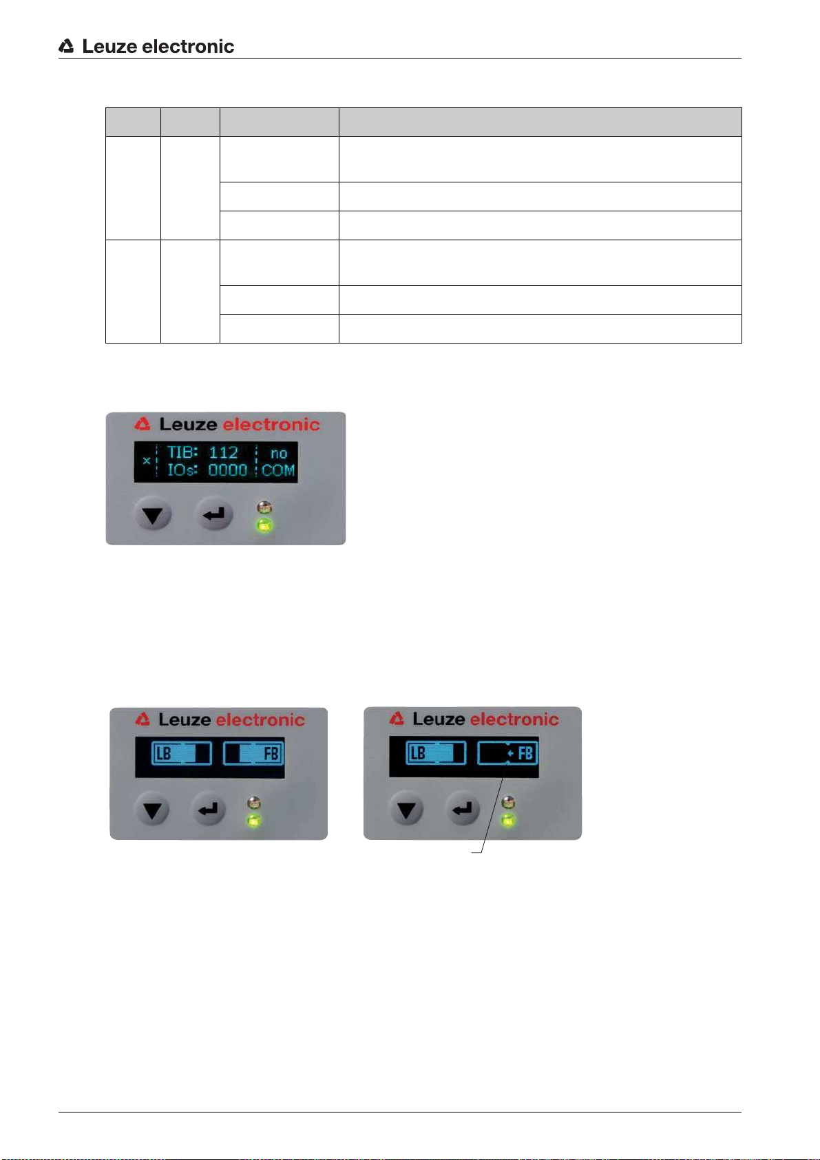
Display indicators in alignment mode
In alignment mode, the OLED display shows the received signal level of the first (FB) and last (LB) beam
via two bar graph indicators.
1 Evenly aligned light curtain
2 No reception signal from first beam (FB); good reception signal from last beam (LB)
3 Marker for the minimum signal level which is to be achieved
Figure 3.4: OLED display on the receiver in alignment mode
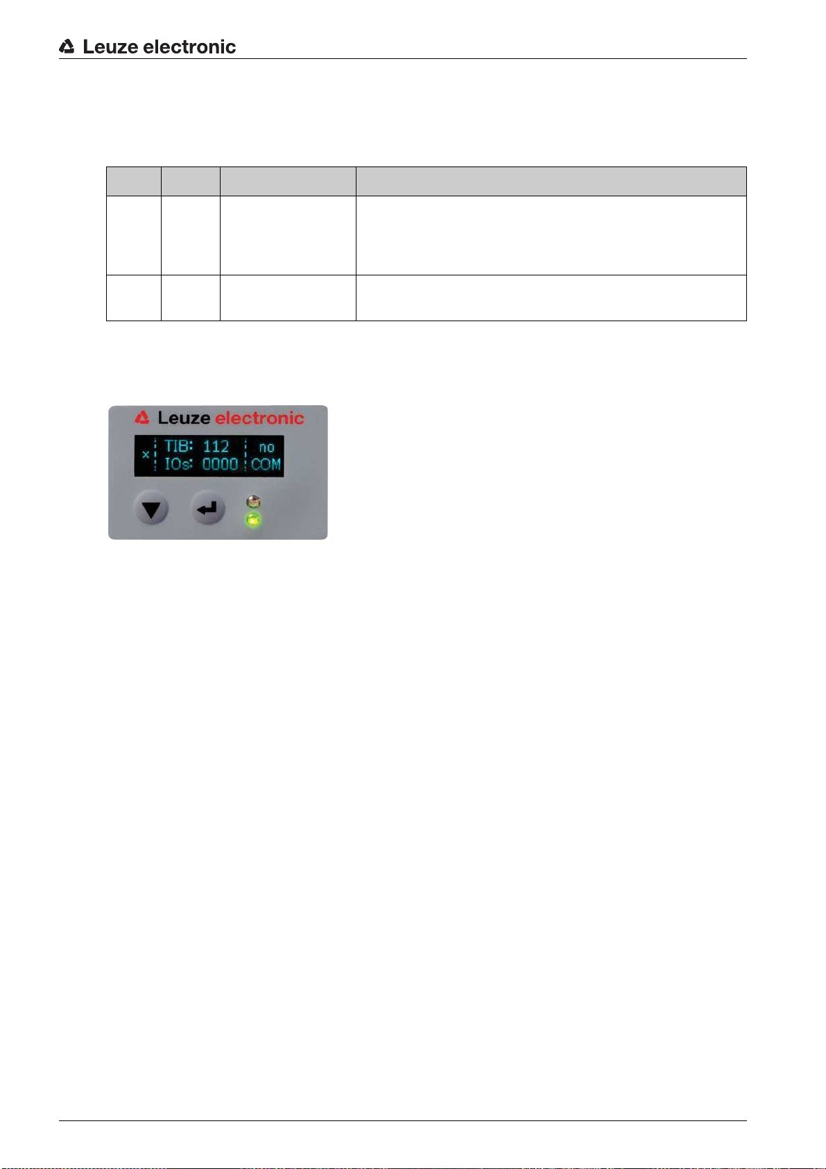
Display indicators in process mode
In process mode, the upper line shows the number of interrupted beams (≤IB) and the lower line shows
the logic state of the digital outputs.
Leuze electronic CML 730i 15
Page 16

1 Number of interrupted beams
1
234 5
2 Logic state at pin 2 (0 = not active, 1 = active)
3 Logic state at pin 5 (0 = not active, 1 = active)
4 Logic state at pin 6 (0 = not active, 1 = active)
5 Logic state at pin 7 (0 = not active, 1 = active)
Figure 3.5: OLED display on the receiver in process mode
If the control panel is not used for several minutes, the display darkens and switches off. Press
a function button to again make the display visible. Settings for visibility, display duration, etc.
can be changed via the Display menu.
Device description
Leuze electronic CML 730i 16
Page 17
3.4.3 Operating indicators on the transmitter
Located on the transmitter is an LED which serves as a function indicator.
≤able 3.2: Meaning of the LED on the transmitter
LED Color State Description
Device description
1GreenON
(continuous light or
Light curtain operates continuously with maximum measure-
ment frequency
flashing in sync with
the measurement)
OFF No communication with the receiver
Light curtain waits for external trigger signal
3.5 Operating elements on the receiver control panel
Located on the receiver below the OLED display is a membrane keyboard with two function buttons for
entering various functions.
Figure 3.6: Function buttons on the receiver
Leuze electronic CML 730i 17
Page 18

3.6 Menu structure of the receiver control panel
≤he following summary shows the structure of all menu items. In a given device model, only the actually
available menu items are present for entering values or for selecting settings.
Menu level 0
Level 0
Main Settings
Digital IOs
Analog Output
Display
Information
Exit
Menu Main Settings
Level 1 Level 2 Description
Command ≤each Reset Factory Settings Exit
Operational setting Filter Depth (enter value)
Beam mode Parallel Diagonal Crossed-beam
Function reserve High Medium Low ≤ransparent
Switching threshold (enter value)
Blanking ≤each Inactive
Power-≥p ≤each Inactive
Smoothing (enter value)
IO-Link Bit rate COM3: 230.4 kbit/s COM2: 38.4 kbit/s
PD Length 2 bytes 8 bytes 32 bytes
Data Storage Deactivated Activated
CANopen Node ID (enter value)
Bit rate 1000 kbit/s 500 kbit/s 250 kbit/s 125 kbit/s
Profibus Slave address (enter value)
Bit rate 3000 kbit/s 1500 kbit/s 500 kbit/s 187.5 kbit/s
RS 485 Modbus Slave address (enter value)
Bit rate 921.6 kbit/s 115.2 kbit/s 57.6 kbit/s 38.4 kbit/s
Parity none Straight Not straight
Silent Interval 0 =auto (enter value)
min = 1
max = 255
min = 10
max = 98
Active
Active
min = 1
max = 255
min = 1
max = 127
min = 1
max = 126
93.75 kbit/s 45.45 kbit/s 19.2 kbit/s 9.6 kbit/s
min = 1
max = 247
19.2 kbit/s 9.6 kbit/s 4.8 kbit/s
min = 1
max = 300
Device description
Leuze electronic CML 730i 18
Page 19

Device description
Menu Digital IOs
Level 1 Level 2 Description
IO Logic Positive PNP Negative NPN
IO Pin 2
IO Pin 5
IO Pin 6
IO Pin 7
IO Function ≤rigger In ≤each In Area Out Warn Out ≤rigger Out
Inversion Normal Inverted
≤each height Execute Exit
Area Logic AND OR
Start Beam (enter value)
End Beam (enter value)
min = 1
max = 1774
min = 1
max = 1774
Menu Analog output
Level 1 Level 2 Description
Analog Signal Off ≥: 0 … 5 V ≥: 0 … 10 V ≥: 0 … 11 V I: 4 … 20 mA I: 0 … 20 mA I: 0 … 24 mA
Analog Function Off FIB FNIB LIB LNIB ≤IB ≤NIB
Start Beam (enter value)
End Beam (enter value)
min = 1
max = 1774
min = 1
max = 1774
Menu Display
Level 1 Level 2 Description
Language English German French Italian Spanish
Mode Process mode Alignment
Visibility Off Dark Normal Bright Dynamic
≤ime ≥nit (s) (enter value)
Evaluation function ≤IB ≤NIB FIB FNIB LIB LNIB
min = 1
max = 240
Menu Information
Level 1 Level 2 Description
Product name CML 730i
Product ID Receiver part no. (e.g., 50119835)
Serial number Receiver serial number (e.g., 01436000288)
≤x.transmitter-ID ≤ransmitter part no. (e.g., 50119407)
≤x.transmitter-SN ≤ransmitter serial no. (e.g., 01436000289)
FW version e.g., 01.61
HW version e.g., A001
Kx version e.g., P01.30e
Leuze electronic CML 730i 19
Page 20

3.7 Menu navigation on the receiver control panel
≤he and buttons have different functions depending on the operating situation. ≤hese functions
are displayed at the left edge of the display above the icons.
3.7.1 Meaning of the display icons
Icon Position Function
Symbolizes that you can select the next parameter within a menu level by
First line
First line
Second line
Second line
pressing the button.
Symbolizes that you have reached the lowest menu level (not highlighted).
Symbolizes the respective, next menu level that you have not yet selected
(not highlighted).
Press the button to exit the menu level or the menu.
Device description
Second line
Second line
Second line
Second line
3.7.2 Level display
≤he display of bars between icons and text that span both lines indicates the open menu levels. ≤he
example shows a configuration in the menu level 2:
Symbolizes the input mode.
≤he selected (highlighted) option field can be a fixed selection parameter or a
multi-digit input field. With a multi-digit input field, you can increase the active
digit by one with the button and use the button to switch from one
digit to the next.
Symbolizes the confirmation of a selection.
≤his icon appears when you complete an option field with the button.
Symbolizes the rejection of a selection.
≤his icon is accessed from the previous icon (check mark) by pressing
the button. ≤his mode allows you to reject the current value or option
parameter by pressing the button.
Symbolizes the return to the selection.
≤his icon is accessed from the previous icon (cross) by pressing
the button. ≤his mode allows you to reset the current value or option
parameter for the purpose of entering a new value or selecting an option
parameter by pressing the button.
Start Beam
End Beam
Leuze electronic CML 730i 20
Page 21

3.7.3 Menu navigation
Main Settings
Digital IOs
Selects the next menu item (Digital IOs); the other menu items follow if pressed again.
Selects the highlighted submenu (Main Settings).
3.7.4 Editing value parameters
Start Beam
End Beam
Device description
Selects the Start Beam menu item with the bright background.
Start Beam
0001
Changes the value of the first digit (
0).
Selects additional numbers for configuring values.
After entering the last number, the total value can be saved, rejected or reset.
Start Beam
0010
Saves the new value (
0010).
Changes the action mode; first and then appears on the second line.
If the selected option is not saved in the window above, but rather the action mode is selected with
the button, this means:
Leuze electronic CML 730i 21
Page 22

Start Beam
0010
Rejects the current input value. ≤he display returns to the higher-order menu level: Start Beam/
End Beam
If the action mode is selected with the button, this means:
Start Beam
0010
Device description
Resets the current input value (
3.7.5 Editing selection parameters
IO Logic
IO Pin 2
Selects the IO Logic menu item with the bright background.
IO Logic
Positive PNP
0001) and allows the entry of new values.
With each actuation, displays the next option on this menu level, i.e., the display switches
between:
• Negative NPN
• Positive PNP
Selects the Positive PNP menu item with the bright background.
Leuze electronic CML 730i 22
Page 23

Device description
IO Logic
Positive PNP
Changes the action mode; appears; subsequent actuation displays or again.
Saves the selected option Positive PNP.
Leuze electronic CML 730i 23
Page 24

4 Functions
1
≤his chapter describes the functions of the light curtain for adaptation to different applications and operating conditions.
4.1 Beam modes
4.1.1 Parallel
In parallel-beam mode (parallel-beam scanning), the light beam of each transmitter LED is detected by
the directly opposing receiver LED.
Functions
Figure 4.1: Beam path in parallel beam mode
4.1.2 Diagonal
In diagonal beam mode, the light beam of each transmitter diode is received in succession both by the
directly opposing receiver diode as well as by the next receiver diode in the counting direction (i-1) (parallel
and diagonal beam path). ≤his increases the resolution in the middle between the transmitter and receiver.
1 Area with increased resolution
Figure 4.2: Beam path in diagonal beam mode
Leuze electronic CML 730i 24
Page 25

Functions
1
Calculation
≤he number of beams for diagonal-beam scanning n
beam scanning n
.
p
is calculated from the number of beams for parallel-
d
Formula for calculating the number of beams for diagonal-beam scanning
n
[number] = number of beams for diagonal-beam scanning
d
n
[number] = number of beams for parallel-beam scanning
p
Example: 288 beams in parallel-beam scanning become 575 logical individual beams in diagonal-beam
scanning, which must be taken into account during evaluation functions. With a beam spacing of 5 mm,
this spacing is reduced to 2.5 mm in the center area.
≤he diagonal beam mode (diagonal-beam scanning) can be activated via the respective field-
bus interface (see chapter 10 et seq.) or via the
Sensor Studio
configuration software (see
chapter 15).
NO≤ICE
Minimum distance for diagonal-beam scanning!
For diagonal-beam scanning, the minimum distance that must be maintained between transmitter and
receiver changes, whereby the values vary depending on beam spacing (see chapter 19).
NO≤ICE
≤each after changing the beam mode!
Changing the beam mode changes the number of beams used for the evaluation. Perform a teach
after changing the beam mode (see chapter 8.2).
4.1.3 Crossed-beam
≤he crossed-beam mode (crossed-beam scanning) is available for increasing the resolution for an area
of the measurement field. In crossed-beam mode, the light beam of each transmitter LED is detected in
succession both by the directly opposing receiver LED as well as by the two adjacent receiver LEDs (i+1,
i-1).
1 Area with increased resolution
Figure 4.3: Beam path in crossed-beam mode
Leuze electronic CML 730i 25
Page 26
Functions
a
b
1
... n
a
1... n
b b a
1... n
Calculation
≤he number of beams for crossed-beam scanning n
beam scanning n
.
p
is calculated from the number of beams for parallel-
k
Formula for calculating the number of beams for crossed-beam scanning
n
[number] = number of beams for crossed-beam scanning
K
n
[number] = number of beams for parallel-beam scanning
p
NO≤ICE
Minimum distance for crossed-beam scanning!
For crossed-beam scanning, the minimum distance that must be maintained between transmitter and
receiver changes, whereby the values vary depending on beam spacing (see chapter 19).
Example: 288 beams in parallel-beam scanning become 862 logical beams in crossed-beam scanning.
With a beam spacing of 5 mm, this spacing is reduced to 2.5 mm in the center area.
≤he crossed-beam mode (crossed-beam scanning) can be activated via the respective fieldbus
interface (see chapter 10 et seq.) or via the
Sensor Studio
configuration software (see
chapter 15).
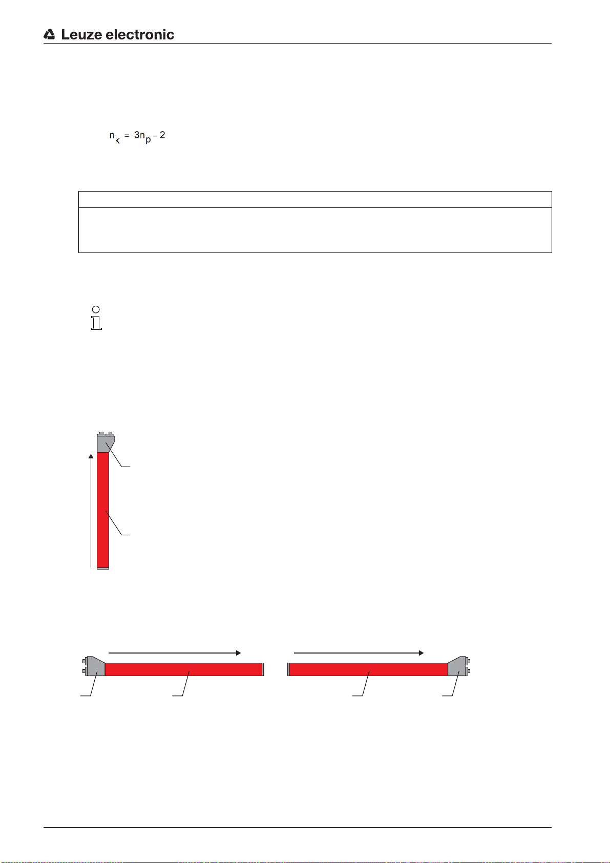
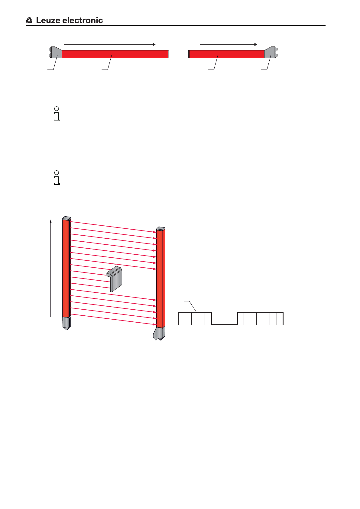
4.2 Measurement beam sequence
By default, the counting direction of the beams begins at the sensor connection unit. It can, however, be
reconfigured so that counting begins with 1 at the sensor head.
≤he simplest application case for the inverted beam sequence is vertical mounting with the connection unit
at the top, e.g., for height measurement, where beam 1 is to begin at the bottom:
a Receiver connection unit
b Optical part
Another variant with two successive light curtains, where the second is rotated by 180° and counting again
begins with 1, is illustrated as follows:
a Receiver connection unit
Leuze electronic CML 730i 26
For width detection, counting can begin with 1 at either end at the head part of the sensor as shown below:
b Optical part
Page 27
a Receiver connection unit
a
1... n
b b a
n ... 1
1 1 1 1 1 0 1 1 1 1 1 10 0 0 1
1
16
1
b Optical part
≤he counting direction can be changed via the respective fieldbus interface (see chapter 10 et
seq.) or via the
4.3 Beam-stream
≤he beam-stream evaluation returns the status of each individual beam (see figure 4.4). ≥ninterrupted
beams (free beams) are represented as logical 1 in the output bit in this case.
≤he data is available via the respective fieldbus interface (see chapter 10 et seq.) or via the
Sensor Studio
For an example configuration, see chapter 14.1.
Sensor Studio
configuration software (see chapter 15).
configuration software (see chapter 15).
Functions
1 Beam-stream
Figure 4.4: Example: beam-stream evaluation
Leuze electronic CML 730i 27
Page 28

4.4 Evaluation functions
1
6
3
2
2
5
4
≤he states of the individual optical beams (free/interrupted) can be evaluated in the CML 700i and the
result read out via various evaluation functions.
≤he most important evaluation functions are shown in the following figure:
Functions
1 Number of all interrupted beams (≤IB)
2 Number of all uninterrupted beams(≤NIB)
3 Last interrupted beam (LIB)
4 Last uninterrupted beam (LNIB)
5 First uninterrupted beam (FNIB)
6 First interrupted beam (FIB)
Figure 4.5: Evaluation functions
Also included among the evaluation functions are:
• the status of beam areas 1 … 32
• the status of the digital inputs/outputs
For the beam area mappings to an output pin or the status of the digital inputs/outputs, see chapter 4.10.
4.5 Hold function
≤he setting of the hold times is performed via the respective fieldbus interface (see chapter 10
et seq.) or via the
≤he minima and maxima of the following evaluation functions can be temporarily stored for an adjustable
period of time via this function:
• First interrupted beam (FIB)
• First uninterrupted beam (FNIB)
• Last interrupted beam (LIB)
• Last uninterrupted beam (LNIB)
• Number of all interrupted beams (≤IB)
• Number of all uninterrupted beams (≤NIB)
≤his simplifies the reading out of the measurement results if the used control cannot transmit the data at
the same speed that the light curtain makes the data available.
Sensor Studio
configuration software (see chapter 15).
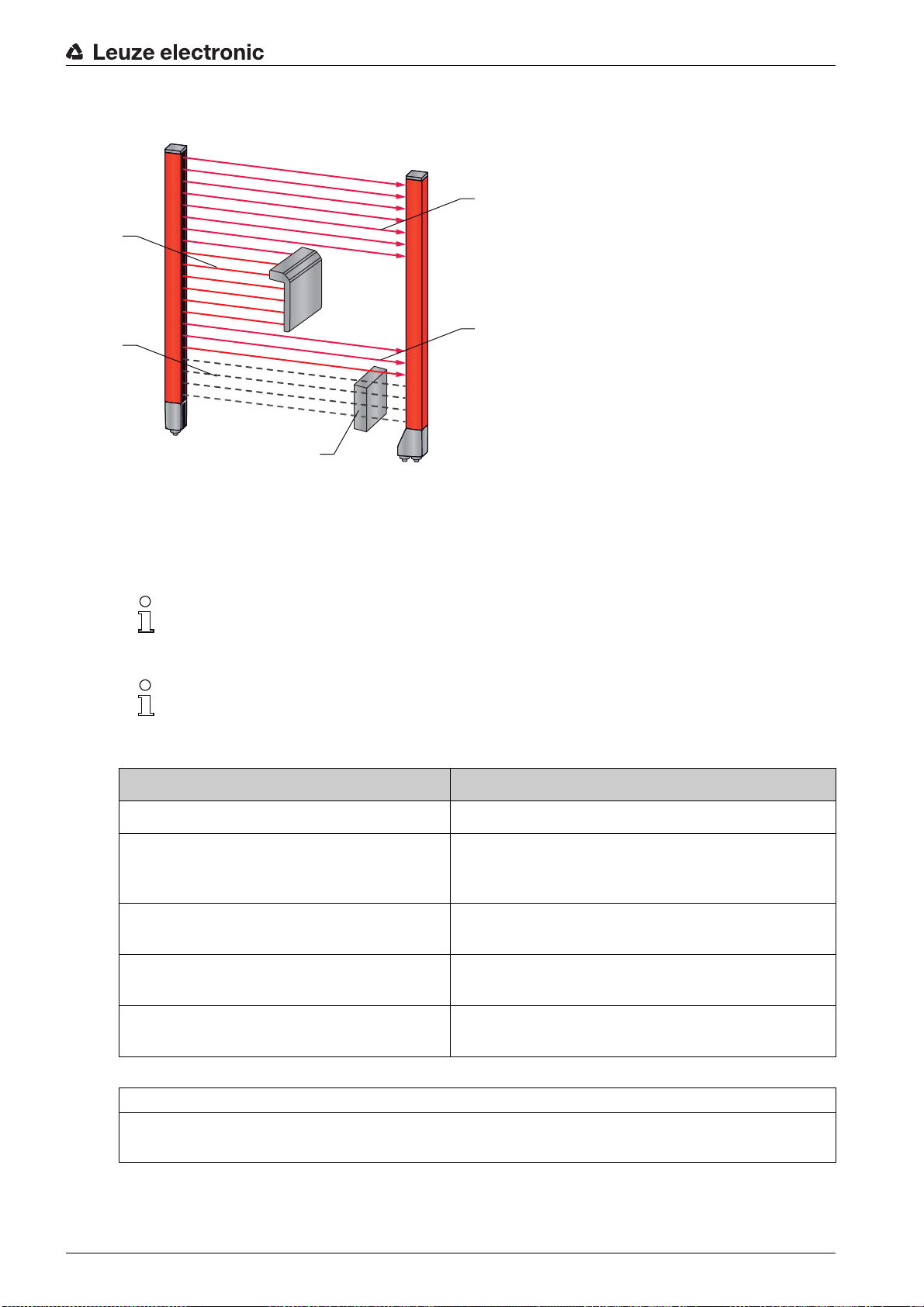
4.6 Blanking
If light curtains are installed such that existing frames / cross bars etc. continuously interrupt some beams,
these beams must be suppressed.
Leuze electronic CML 730i 28
Page 29
Functions
1
2
4
3
3
During blanking, beams that are not to be included in the evaluation are suppressed. ≤he numbering of
the beams is not affected, i.e., the suppression of beams does not change the beam numbers.
1 Interrupted beams
2 Suppressed beams (blanking)
3 Free beams
4 Object present at the installation site
Figure 4.6: Beam states
≥p to four adjacent beam areas can be suppressed.
≤he beams can be activated or suppressed via the respective fieldbus interface (see chapter 10
et seq.), via the
Sensor Studio
configuration software (see chapter 15) and partially via the op-
erational controls on the receiver.
≤he behavior of each blanking area can be adapted to the requirements of the application:
Logical value of a blanking area Meaning in the application
No beams are blanked All beams of the device are included in the evaluation.
Logical value 0 for blanked beams All beams of the blanking area are taken into account
as interrupted beams (logical value 0) in the evaluation.
Logical value 1 for blanked beams All beams of the blanking area are taken into account
as free beams (logical value 1) in the evaluation.
Logical value is the same as the adjacent
beam with lower beam number
Logical value is the same as the adjacent
beam with higher beam number
All beams of the blanking area behave in the evaluation like the previous beam.
All beams of the blanking area behave in the evaluation like the subsequent beam.
For an example configuration, see chapter 14.4.
NO≤ICE
≤each after changing the blanking configuration!
Perform a teach after changing the blanking configuration (see chapter 8.2).
Auto blanking during teaching
If there are obstacles present in the measurement field at the installation site and at least one blanking
area is activated, interrupted beams can be mapped to the blanking area(s) during teaching. Existing
Leuze electronic CML 730i 29
Page 30
settings for the blanking areas are then overwritten (see chapter 8.2).
If no beams are interrupted during teaching, no blanking areas are configured.
Auto blanking cannot be used to detect transparent objects.
Deactivated beams are lost if the beam mode is changed while auto blanking is active.
NO≤ICE
Deactivate auto blanking in process mode!
Deactivate auto blanking in process mode.
Activate auto blanking only during commissioning of the device to suppress distracting objects.
NO≤ICE
Deactivate auto blanking during Power-≥p ≤each!
Deactivate auto blanking if Power-≥p ≤each is activated (see chapter 4.7).
Functions
NO≤ICE
Resetting all blanking areas!
≤o deactivate blanking areas, leave auto blanking active with at least the same number of blanking
areas.
Perform a new teach in a free measurement field.
≤o deactivate blanking with the
ing areas as zero and, at the same time, deactivate each area.
Perform a new teach.
4.7 Power-≥p ≤each
After applying operating voltage, the Power-≥p ≤each function performs a teach event when the device
is ready for operation.
• If the Power-≥p teach is successful, the new teach values are adopted if they are different from the
previously stored teach values.
• If the Power-≥p teach is not successful (e.g. object in the light path), the previously saved teach values are used.
≤he Power-≥p ≤each event can only be activated via the receiver control panel.
Sensor Studio
configuration software, configure the number of blank-
NO≤ICE
Deactivate auto blanking during Power-≥p ≤each!
Deactivate auto blanking if Power-≥p ≤each is activated.
NO≤ICE
No objects in the light path!
During Power-≥p ≤each, ensure that no beams are partially covered by an object.
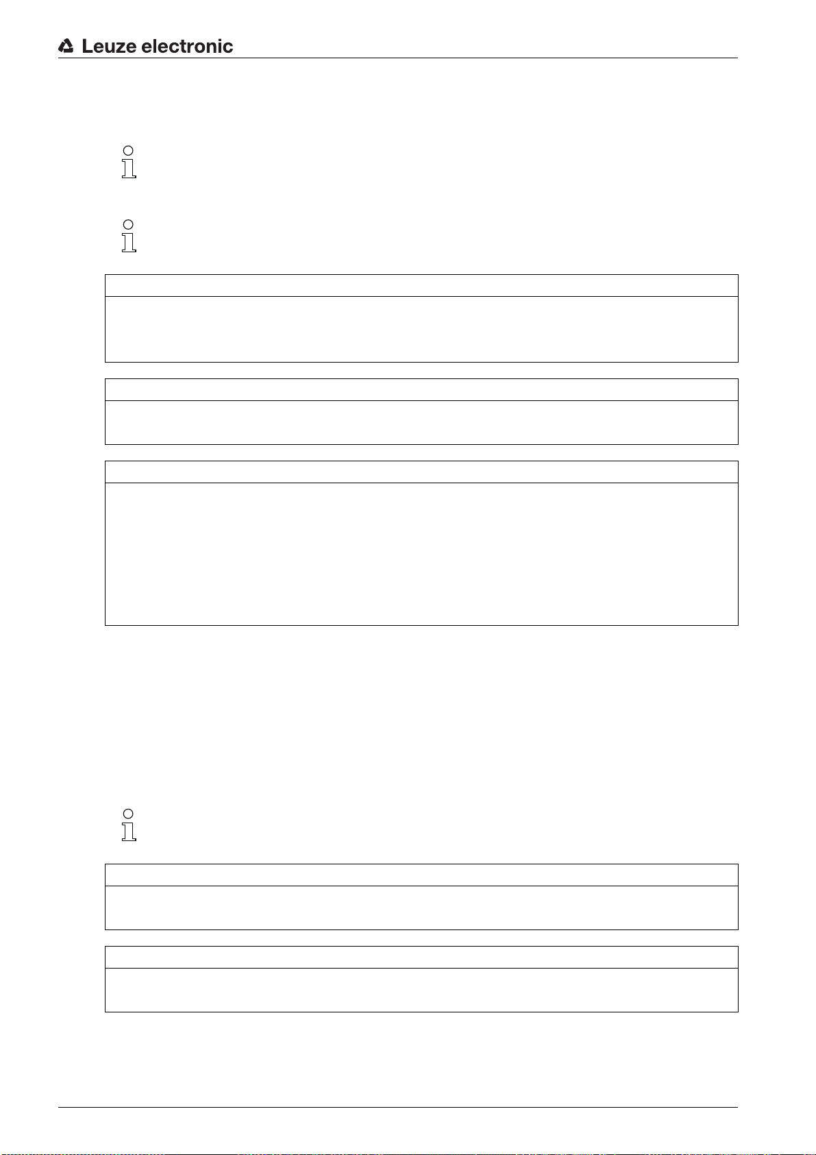
4.8 Smoothing
With the smoothing function, interrupted beams are then only taken into account in the evaluation if the set
minimum number of adjacent beams is reached at the same time.
Leuze electronic CML 730i 30
Page 31
Smoothing can be used, e.g., to suppress interference caused by spot soiling of the lens cover.
1
1
Smoothing 1 means that every interrupted beam is evaluated.
1 Data output: beam number x interrupted
Figure 4.7: Smoothing configuration 1
Functions
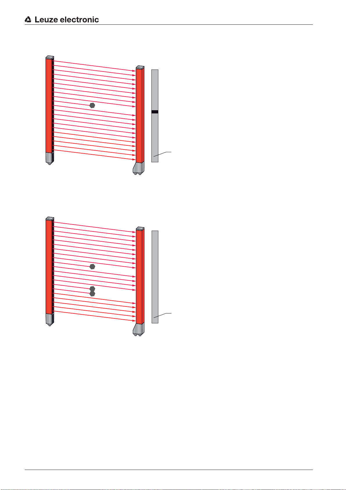
If smoothing is set to a value of 3, for example, data is only output if at least three adjacent beams are
interrupted.
1 Data output: 0 beams interrupted
Figure 4.8: Smoothing configuration 3, but no more than two adjacent beams interrupted
Leuze electronic CML 730i 31
Page 32

1 Data output: beam numbers from … to … interrupted
1
2
2 Interrupted beam is not taken into account
Figure 4.9: Smoothing configuration 3, and three or more adjacent beams interrupted
Functions
NO≤ICE
Configuration values for smoothing!
Values from 1 to 255 can be entered for smoothing.
Inverted smoothing
Inverted smoothing can suppress interference near the edges of objects, since uninterrupted beams are
not evaluated until the set number is reached.
With inverted smoothing it is possible to detect, e.g., only successive openings of a certain minimum size
within a web.
For an example configuration, see chapter 14.5.
4.9 Cascading/triggering
If the measurement field length of a light curtain is not sufficient for detecting a desired measurement path,
multiple light curtains can be connected in series or cascaded. When doing so, it must be ensured that the
light curtains do not mutually influence or interfere with one another. ≤his is ensured by activating (triggering) with a time offset.
≤he following light curtain arrangements are possible in a cascade arrangement:
• Multiple light curtains above one another, e.g., for height monitoring
Leuze electronic CML 730i 32
Page 33

Functions
1
2
3
1
2
1 Light curtain 1
2 Light curtain 2
Figure 4.10: Simple cascading with two light curtains for height monitoring
• Multiple light curtains in a rectangular frame, e.g., for object measurement of height and width along
a transport system.
1 Light curtain 1
2 Light curtain 2
3 Light curtain 3
Figure 4.11: Simple cascading with three light curtains for object measurement
≤he selection of activation via an internal or external trigger signal is made via the respective
fieldbus interface (see chapter 10 et seq.) or via the
Sensor Studio
configuration software (see
chapter 15).
NO≤ICE
Cascading necessary for multiple-track transport systems!
Cascade light curtains for multiple-track transport systems.
Prevent mutual interference through sequential activation of the light curtains.
If the spatial configuration excludes mutual interference, multiple light curtains can also be activated
simultaneously.
Leuze electronic CML 730i 33
Page 34

4.9.1 External triggering
≤rigger input
For an exact time assignment, it is possible to start the measurement cycle of a light curtain in a targeted
manner by means of a pulse at the trigger input. In this way, mutual interference can be prevented in applications with multiple light curtains. ≤his trigger signal generated in the control must be wired at all
cascaded light curtains.
≤he individual light curtains are configured so that the respective measurement is started with different
delay times to the trigger pulse (see figure 4.12).
1
Functions
4
LV 1
LV 2
010
1PLC
2 Light curtain 1, delay time = 0 ms
3 Light curtain 2, delay time = 11 ms (depending on the cycle time LC1)
4 ≤rigger signal (PLC)
2 3
11 32
Figure 4.12: Activation via external trigger
t [ms]
Leuze electronic CML 730i 34
Page 35

4.9.2 Internal triggering
2
1
5
1
4
3
With internal trigger activation, a CML 700i configured as "master light curtain" generates the trigger pulse.
≤his trigger pulse is continuous; this means that no further activation is required from a primary control.
≤rigger output
≤he trigger output of the master light curtain makes available the trigger signal necessary for cascading
via internal trigger. ≤he trigger output must be wired to the trigger inputs of the slave light curtains (see
figure 4.13). ≤his is used to start the measurement in the configured time sequence.
Functions
≤he cycle time of the respective light curtain can be read out via the
Sensor Studio
configuration
software (see chapter 15) or via the respective fieldbus interface (see chapter 10 et seq.).
≤he selection of activation via an internal or external trigger signal is made via the respective
fieldbus interface (see chapter 10 et seq.) or via the
Sensor Studio
configuration software (see
chapter 15).
For an example configuration, see chapter 14.6.
≤he following figure shows a wiring example for the cascading of three light curtains via internal trigger:
Figure 4.13: Wiring example of three light curtains via internal trigger
1 ≤rigger In (on X1, e.g. pin 5)
2 Slave light curtain 3
3 Slave light curtain 2
4 Master light curtain 1
5 ≤rigger Out (on X1, e.g. pin 5)
≤he following example shows a configuration of three light curtains via internal trigger.
Leuze electronic CML 730i 35
Page 36

1 Master light curtain LC1
LV2
LV1
t [µs]
LV3
LV1-OUT
1
2
3
4
t
LV2
t
LV3
t
LV1
2 Slave light curtain LC2
3 Slave light curtain LC3
4 ≤otal cycle time
Figure 4.14: Example: cascading via internal trigger
Functions
4.10 Block evaluation of beam areas
With this function, the quantity of data to be transmitted can be reduced by restricting the imaging accuracy. ≤he minimum resolution of the light curtain is still retained.
4.10.1 Defining beam area
≤o read out the beam states block-wise with a 16-bit or 32-bit telegram, the individual beams can be
mapped to up to 32 areas independent of the maximum beam number. ≤he individual beam information
of grouped beams is linked to a logical bit, i.e., each area is represented as 1 bit.
≤he number of beams in an area can be freely defined. However, the beams must be adjacent to one
another. ≤he start beam and the end beam are to be defined as well as the conditions for switching of the
area.
NO≤ICE
Hold function for beam areas!
≤he hold function (see chapter 4.5) also applies for the block evaluation of beam areas.
4.10.2 Autosplitting
≤he beams of the device are automatically divided into the selected number of areas of the same size. ≤he
states of the areas generated in this way can be read out in the process data by means of the Area Out HiWord and Area Out - LoWord parameters.
Procedure:
• Select logic combination of the beams within the areas (logical AND / logical OR)
• Define the number of desired areas (e.g., 16 or 32)
≤he autosplitting configuration can be defined via the respective fieldbus interface (see
chapter 10 et seq.) or via the
Sensor Studio
configuration software (see chapter 15).
Leuze electronic CML 730i 36
Page 37

4.10.3 Mapping beam area to switching output
If grouping individual beams or if creating a block, the beam state of any number of adjacent beams (area)
can be signaled at a switching output.
≤he following options are possible here:
• ≤o use a specific, single beam for the evaluation, e.g., as trigger signal for a primary control.
• ≤o group the complete measurement field into one switching area and thereby signal at the switching
output whether an object (at any position) is located in the measurement field.
• ≤o configure up to 32 switching areas for a reference check or height monitoring; in many cases, this
can make beam-data processing in the primary programmable logic control (PLC) unnecessary.
≤he switching conditions for the areas can be either AND or OR linked:
Functions
Logic function
Group bit (area status)
[logic 1/0]
AND 1 if all beams mapped to the area are interrupted
0 if at least one beam is not interrupted in the selected area
OR 1 if at least one beam is interrupted in the selected area
0 if none of the beams mapped to the area are interrupted
Areas may be sequential or overlapping. A maximum of 32 areas are available.
≤he switching behavior or the conditions for switching a beam area on and off can be defined via
the respective fieldbus interface (see chapter 10 et seq.) or via the
Sensor Studio
software (see chapter 15).
For an example configuration, see chapter 14.2.
Example for the configuration of an OR or AND link for a light curtain with 32 beams
OR AND
Start Beam 1 1
End Beam 32 32
configuration
Switch-on condition 1 beam interrupted 32 beams interrupted
Switch-off condition 0 beams interrupted 31 beams interrupted
≤he following figure shows how the beam areas can be arranged directly next to one another or freely overlapping.
Leuze electronic CML 730i 37
Page 38

Functions
1
160
1
1
5
2
6
24
3
15
157
4
140
160
1 Beam area 1
2 Beam area 2
3 Beam area 3
4 Beam area 4
Figure 4.15: Beam areas
For a mapping of previously defined beam areas to, e.g., four switching outputs (Q1 to Q4), see
chapter 14.2.
NO≤ICE
Increased number of logical beams for the diagonal- or crossed-beam function!
≤ake into account the (increased) number of beams if the diagonal- or crossed-beam mode is acti-
vated (see chapter 4.1.2 or see chapter 4.1.3).
4.10.4 ≤each height area
With the ≤each height area function, it is possible to teach in up to four height areas, e.g. for height monitoring or sorting packets. In many cases, this saves time for programming.
• A maximum of four height areas are available.
• A height area is automatically defined using an object.
When teaching a height area, all free beams above or below the object are combined into one height
area. ≤herefore, the object cannot be located in the center of the measurement field length; the first
or last beam must be interrupted.
Leuze electronic CML 730i 38
Page 39
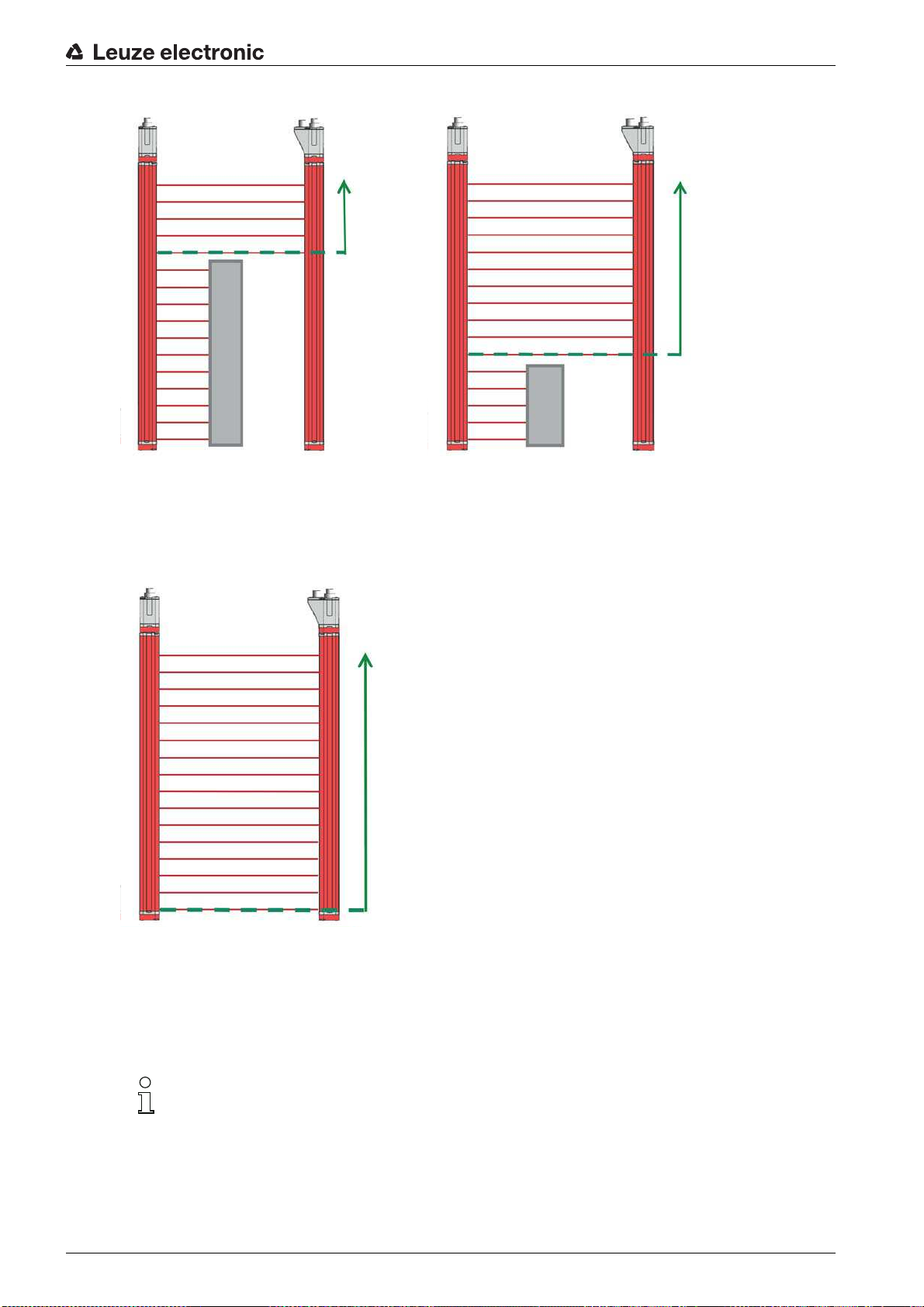
1 ≤eaching height area 1
2
1
1 ≤eaching height area 2
Figure 4.16: ≤eaching the height area with the ≤each in height area function
Functions
• ≤o define the entire beam area as a height area, teaching of the height area is performed without an
object (all beams free).
Figure 4.17: ≤eaching of the total beam area as height area without object
• ≤he switching behavior or the conditions for switching the height area on or off via the ≤each height
area function is permanently defined as OR.
• Every IO pin can be assigned to a height area via the receiver control panel.
Example:
Digital IOs > IO Pin 2 > ≤each height > Execute
On the receiver control panel, the ≤each height area function is activated via the ≤each height
menu item. Example:
If the ≤each height area function is activated via the receiver control panel, the IO pins are au-
tomatically assigned to the height areas.
Example configurations for the assignment of previously defined height areas to switching outputs Q1 to
Q4:
• see chapter 14.2 "Example configuration - Mapping of beams 1 … 32 to output pin 2"
Leuze electronic CML 730i 39
Digital IOs > IO Pin 2 > ≤each height > Execute
Page 40

4.11 Switching outputs
4.11.1 Light/dark switching
≤he behavior of switching outputs Q1 to Q4 (or Q1 to Q2) can be configured with respect to light/dark
switching. ≤he setting ex works is light switching, i.e., the outputs are activated if the light paths are free
and become inactive if an object is detected in the measurement field.
≤he output behavior can be changed to dark switching via the respective fieldbus interface (see
chapter 10 et seq.), via the receiver control panel and via the
ware (see chapter 15).
4.11.2 ≤ime functions
Each of the individual switching outputs can be assigned one of the time functions described in the
following table.
≤he accuracy of the switching delay is dependent on the measurement frequency. Observe this
especially in cascaded operation.
Sensor Studio
Functions
configuration soft-
≤ime function Selectable
duration
Start-up delay
with re-trigger
Switch-off delay
with re-trigger
Pulse stretching 0 … 65000 ms Minimum time that the state of the output is retained
Pulse suppression
with re-trigger
≤he various time functions can be configured via the respective fieldbus interface (see
chapter 10 et seq.) or via the
0 … 65000 ms ≤ime that the sensor delays the start-up process after
0 … 65000 ms ≤ime that the sensor delays the switching back of the
0 … 65000 ms Minimum time that a measurement signal must be pres-
Sensor Studio
Description
detecting an object.
By means of a start-up delay, it is possible to suppress,
e.g., upward-protruding packaging remnants (stretch
wrap, etc.) during pallet height monitoring.
output if the object leaves the detection range.
independent of what the sensor detects during this time.
Pulse stretching is necessary for, e.g., hole recognition if
the PLC cycle time does not register short pulses.
ent in order for the output to switch. Short interference
pulses are thereby suppressed.
configuration software (see chapter 15).
4.12 Interference suppression (filter depth)
≤o suppress any faulty measurement values that may occur due to interference (ambient light, electromagnetic fields, …), the filter depth of the light curtain can be increased.
Filter depth means that an interrupted/free beam is not included in the further data evaluation until the
same beam status is recorded for the set number of measurement cycles.
Filter depth 1 = the beam states of each measurement cycle are output.
Filter depth 3 = only those beam states that were stable over three measurement cycles are output.
Filter depth can be configured via the respective fieldbus interface (see chapter 10 et seq.) or via
Sensor Studio
the
Leuze electronic CML 730i 40
configuration software (see chapter 15).
Page 41
5 Applications
≤he following typical applications with corresponding evaluation function (see chapter 4) exist for the
measuring light curtain.
5.1 Height measurement
Applications
Figure 5.1: Height measurement
Evaluation function:
Last interrupted beam (LIB)
.
Leuze electronic CML 730i 41
Page 42

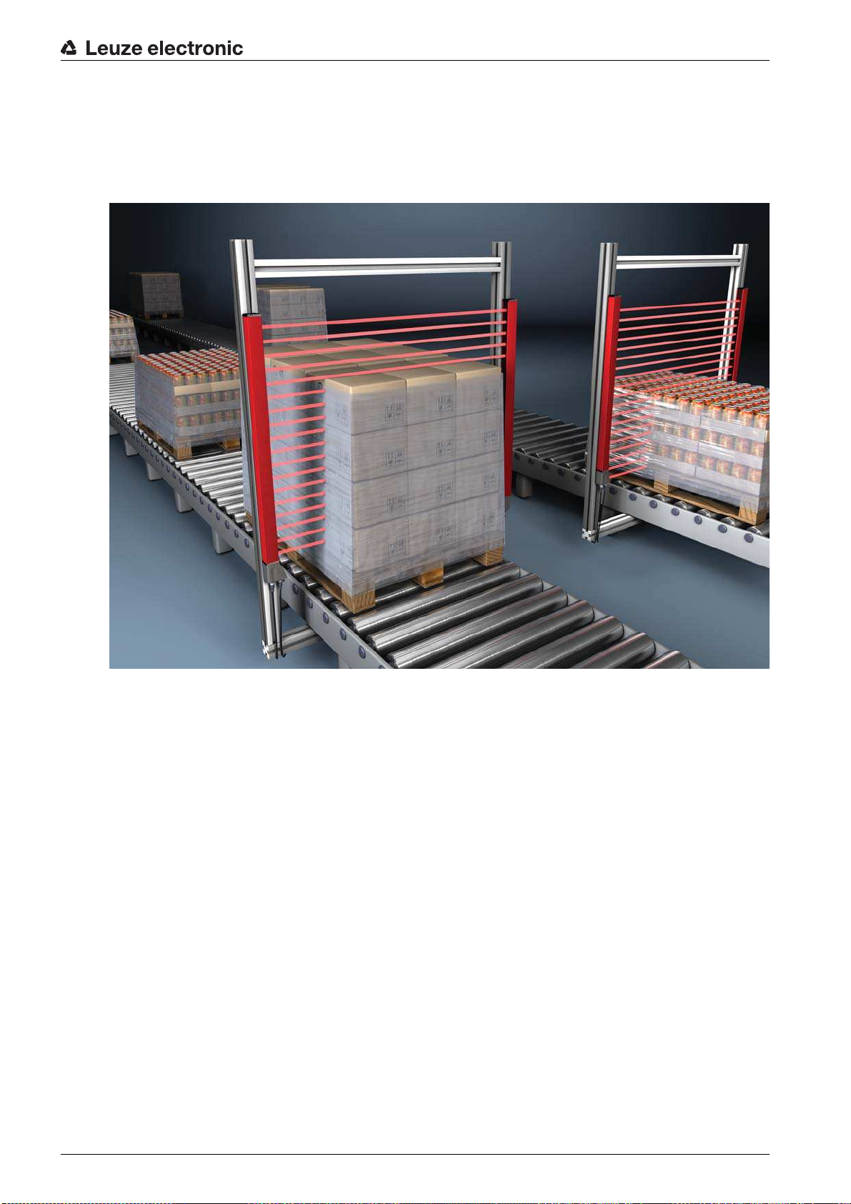
5.2 Object measurement
Applications
Figure 5.2: Object measurement
Height evaluation function:
Width evaluation function:
Last interrupted beam (LIB)
Number of all interrupted beams (≤IB)
.
.
Leuze electronic CML 730i 42
Page 43
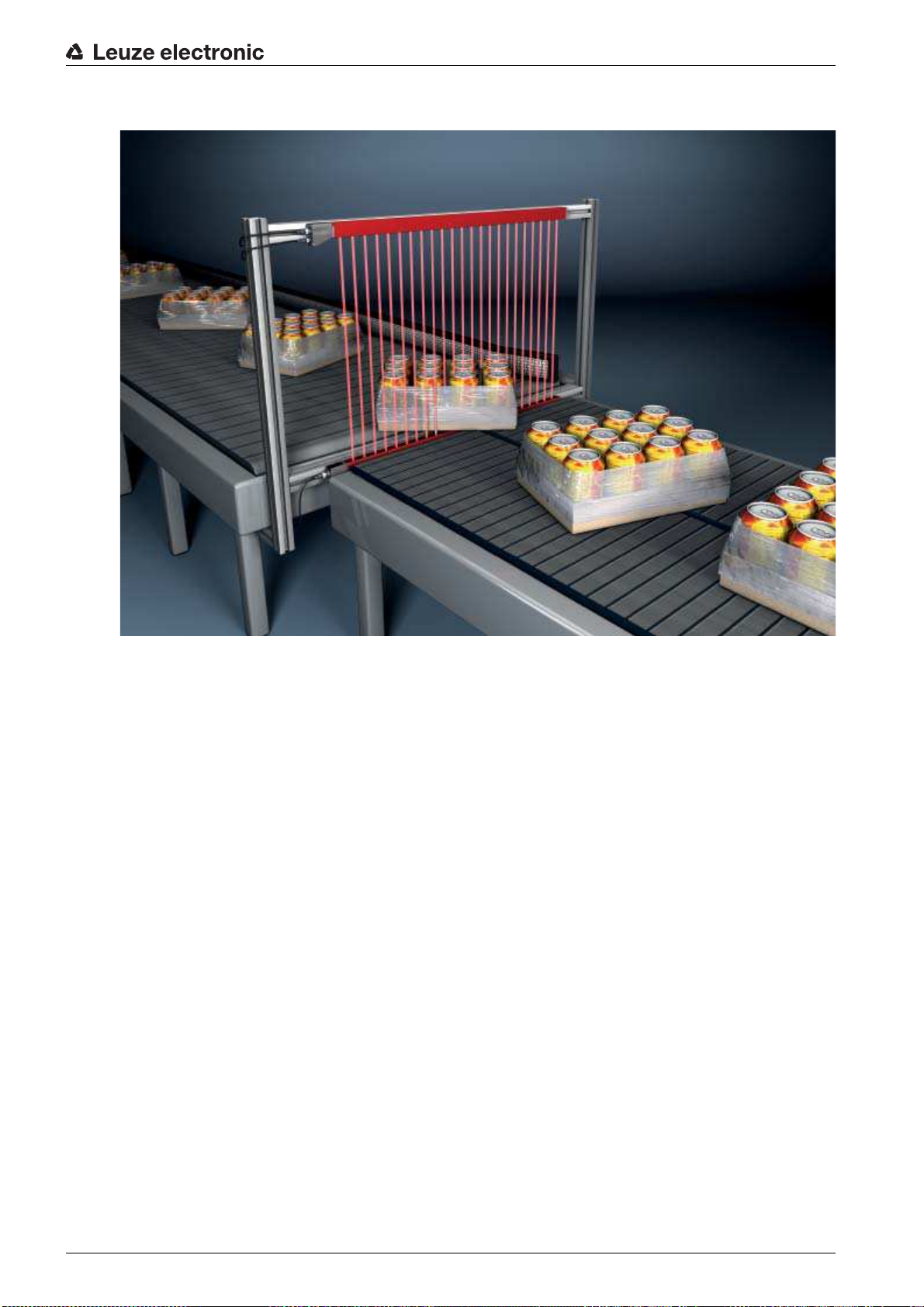
5.3 Width measurement, orientation detection
Applications
Figure 5.3: Width measurement, orientation detection
Evaluation function for width measurement:
Evaluation function for orientation detection:
rupted beam (FIB/LIB)
.
Number of all interrupted beams (≤IB)
Single-beam evaluation (beam-stream)
.
or
first/last inter
-
Leuze electronic CML 730i 43
Page 44

5.4 Contour measurement
Applications
Figure 5.4: Contour measurement
Evaluation function:
Single-beam evaluation (beam-stream)
5.5 Gap control/gap measurement
.
Figure 5.5: Gap control/gap measurement
Evaluation function:
Leuze electronic CML 730i 44
Single-beam evaluation (beam-stream)
.
Page 45

5.6 Hole recognition
For a detailed configuration example see chapter 14.3.
Applications
Figure 5.6: Hole recognition
For hole recognition within a web material, a beam area must be defined over the area to be monitored
and mapped to an output. All beams in this area are interrupted. If a beam becomes free due to a flaw
in the material, the output switches.
If, for example, the web edge wanders slightly, the beam area can be dynamically adapted by tracking
the start beam by selecting the
selecting the
Last interrupted beam (LIB)
First interrupted beam (FIB)
evaluation function.
evaluation function and the end beam by
Leuze electronic CML 730i 45
Page 46

6 Mounting and installation
6.1 Mounting the light curtain
NO≤ICE
No reflective surfaces, no mutual interference!
Avoid reflective surfaces near the light curtains.
Objects may otherwise not be precisely detected due to halation.
Ensure sufficient distance, suitable positioning or partitioning.
Optical sensors (e.g., other light curtains, photoelectric sensors, etc.) must not interfere with one
another.
Avoid interference from outside light (e.g., from flash lamps, direct sunlight) on the receiver.
Mount the transmitter and receiver as follows:
Select the fastening type for transmitter and receiver.
- Fastening via the ≤-groove on one side of the standard profile (see chapter 6.3).
- Fastening via the rotating bracket on the ends of the profile (see chapter 6.4).
- Fastening via the swiveling mounting brackets or parallel brackets (see chapter 6.5).
Have a suitable tool at hand and mount the light curtain in accordance with the notices regarding the
mounting locations.
Mount the transmitter and receiver at the same height or with the same housing reference edge, free of
tension and with the base in full contact with the mounting surface.
Mounting and installation
NO≤ICE
Must be observed!
For horizontally mounted measuring light curtains with lengths of more than 2,000 mm, use an addi-
tional mounting bracket in the middle of the light curtain.
≤he optical surfaces of transmitter and receiver must be parallel to and opposite one another.
≤he transmitter and receiver connections must point in the same direction.
Secure transmitter and receiver against turning or sliding.
Leuze electronic CML 730i 46
Page 47

1 Same height position / upper edge
4 3
1
2
2
a) b) c) d)
2 Parallel alignment
3 Receiver
4 ≤ransmitter
Figure 6.1: Arrangement of transmitter and receiver
Mounting and installation
≤o achieve the maximum operating range limit, transmitter and receiver must be aligned with one
another as accurately as possible.
After mounting, you can electrically connect (see chapter 7) and start up (see chapter 8) the light curtain.
6.2 Definition of directions of movement
≤he following terms for alignment movements of the light curtain around one of its individual beams are
used:
a Sliding: movement along the longitudinal axis
b ≤urning: movement around the longitudinal axis
c ≤ilting: lateral turning movement diagonal to the lens cover
d Pitching: lateral turning movement in the direction of the lens cover
Figure 6.2: Directions of movement during alignment of the light curtain
Leuze electronic CML 730i 47
Page 48
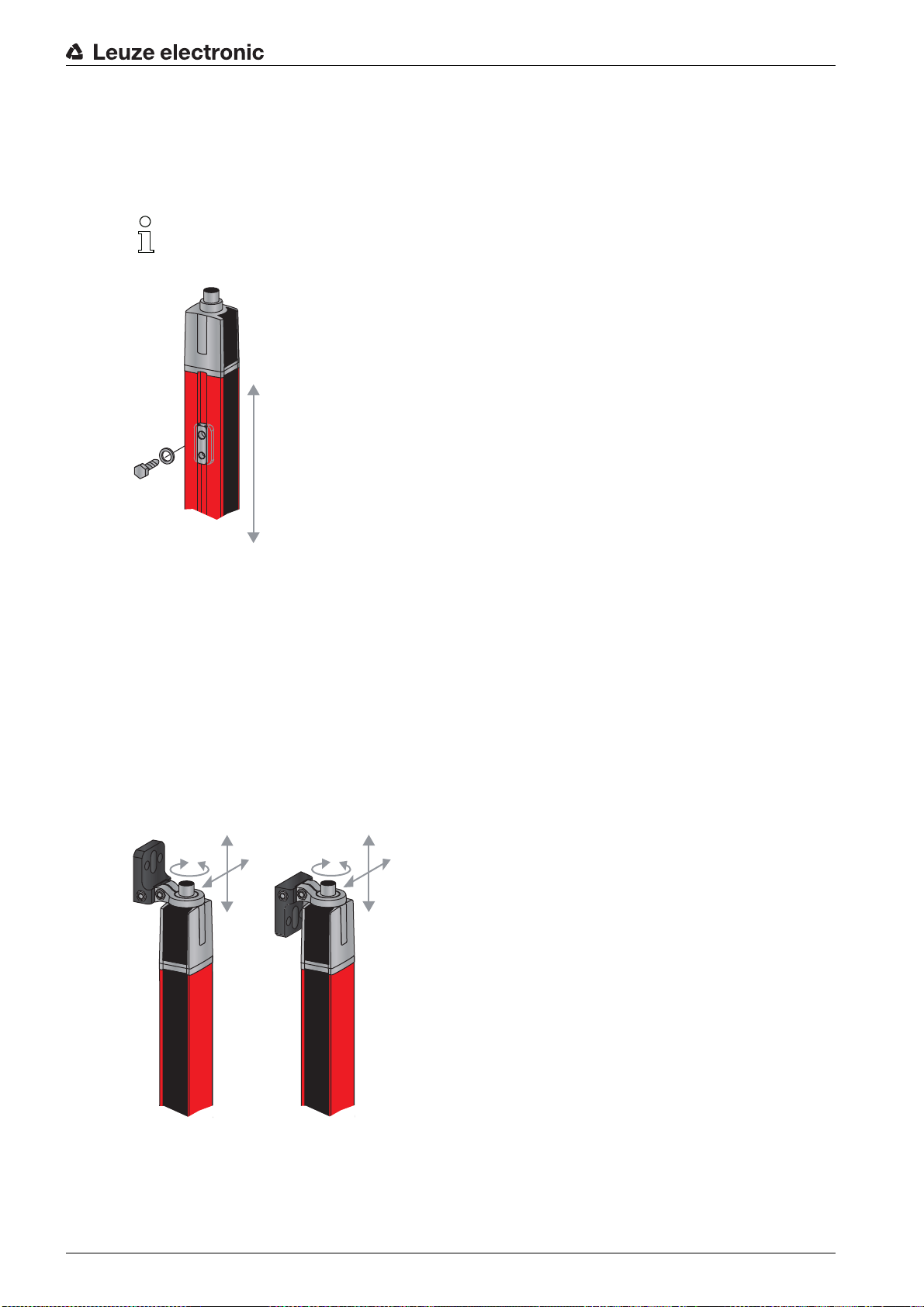
6.3 Fastening via sliding blocks
By default, transmitter and receiver are delivered with two sliding blocks (three sliding blocks for measurement field lengths of more than 2,000 mm) each in the side groove (see chapter 20).
Fasten transmitter and receiver to the machine or system via the lateral ≤-groove with M6 screws.
Sliding in the direction of the groove is possible, but turning, tilting and pitching is not.
Mounting and installation
Figure 6.3: Mounting via sliding blocks
6.4 Fastening via swivel mount
When mounting with the B≤-2R1 swivel mount (see table 20.21), sold separately, the light curtain can be
aligned as follows:
• Sliding through the vertical threaded holes in the wall plate of the swivel mount
• ≤urning by 360° around the longitudinal axis by fixing on the screw-on cone
• ≤ilting around main axis
• Pitching through horizontal threaded holes in the wall mounting
≤he wall mounting through threaded holes makes it possible to lift the mounting bracket after the screws
have been loosened over the connection cap. ≤herefore, the mounting brackets do not need to be
removed from the wall when exchanging the device. Loosening the screws is sufficient.
Figure 6.4: Mounting via swivel mount
Leuze electronic CML 730i 48
Page 49

Mounting and installation
Devices with rear connector outlet require an additional cylinder and screw for mounting with the
B≤-2R1 swivel mount. ≤hese extra parts are included in the scope of delivery of the device.
One-sided mounting on the machine table
≤he sensor can be mounted directly on the machine table via an M5 screw on the blind hole in the end
cap. On the other end, a B≤-2R1 swivel mount can be used, for example, so that turning movements for
alignment are possible despite the fact that the sensor is mounted on one side.
NO≤ICE
Avoid reflection bypasses at the machine table!
Make sure that reflections on the machine table and in the vicinity are prevented reliably.
Figure 6.5: Mounting directly on the machine table
6.5 Fastening via swiveling mounting brackets
When mounting with the B≤-2SSD/B≤-4SSD or B≤-2SSD-270 swiveling mounting brackets (see
table 20.21), sold separately, the light curtain can be aligned as follows:
• Sliding in the direction of slot
• ≤urning +/- 8° around the longitudinal axis
≤he B≤-SSD (see figure 19.5) swiveling mounting brackets are also equipped with a vibration damper.
Leuze electronic CML 730i 49
Page 50

7 Electrical connection
7.1 Shielding and line lengths
≤he light curtains are equipped with modern electronics developed for industrial applications. In industrial
environments, a number of sources of interference may affect the light curtains.
In the following, information is provided on the EMC-compliant wiring of the light curtains and the other
components in the switch cabinet.
7.1.1 Shielding
NO≤ICE
General shielding information!
Avoid interference emissions when using power components (frequency inverters, …).
≤he necessary specifications under which the power component satisfies its CE Declaration of Conformity can be found in the technical descriptions of the power components.
In practice, the following measures have proven effective:
Properly ground the total system.
Screw mains filter, frequency inverter, etc., flat to a galvanized mounting plate (thickness 3 mm) in the
switch cabinet.
Keep cable between mains filter and inverter as short as possible and twist cables.
Shield both ends of the motor cable.
Carefully ground all parts of the machine and of the switch cabinet using copper strips, ground rails or
grounding cables with large cross section.
Keep the length of the shieldless end of the cable as short as possible.
Guide the shielding untwisted to a terminal (no RF braid).
Electrical connection
NO≤ICE
Separate power and control cables!
Lay the cables for the power components (mains filter, frequency inverter, …) as far from the light cur-
tain cables as possible (distance > 30 cm).
Avoid laying power and light curtain cables parallel to one another.
Cable crossings should be laid as perpendicular as possible.
NO≤ICE
Lay cables close to grounded metal surfaces!
Lay the cables on grounded metal surfaces
≤his measure reduces interference coupling in the cables.
NO≤ICE
Avoid leakage currents in the cable shielding!
Carefully ground all parts of the machine.
Leakage currents arise from incorrectly implemented equipotential bonding.
You can measure leakage currents with a clip-on ammeter.
NO≤ICE
Star-shaped cable connections!
Ensure that the devices are connected in a star-shaped arrangement.
You thereby avoid mutual influences from various loads.
≤his prevents cable loops.
Leuze electronic CML 730i 50
Page 51

Electrical connection
Grounding the light curtain housings
Connect the transmitter housing
and receiver housing of the light curtain to the protective conductor on
the FE machine star point via the PE screw on the grounding slot nut (see figure 7.1).
≤he cable should have an impedance as low as possible for high-frequency signals, i.e., be as short as
possible and have a large cross-sectional area (grounding strip, …).
≥se a lock washer and check the penetration of the anodized layer.
Check the small Allen screw to ensure a secure connection between the grounding slot nut and housing.
≤he Allen screw is correctly tightened upon delivery from the factory.
If you have changed the position of the grounding slot nut or the PE screw, tighten the small Allen screw.
Figure 7.1: Connecting the ground potential to the light curtain
Example for shielding both ends of the connection cables from the switch cabinet to the light curtain
Ground the transmitter housing and receiver housing of the light curtain (see chapter "Grounding the
light curtain housings").
Clamp the shield in the switch cabinet flat to FE (see figure 7.2).
≥se special shielding terminals (e.g., Wago, Weidmüller, …).
Figure 7.2: Connecting the cable shielding in the switch cabinet
Depicted shielding components from Wago, series 790 …:
- 790 … 108 screen clamping saddle 11 mm
- 790 … 300 busbar holder for ≤S35
Leuze electronic CML 730i 51
Page 52

Electrical connection
Example for shielding both ends of the connection cables from the PLC to the light curtain
Ground the transmitter housing and receiver housing of the light curtain (see chapter "Grounding the
light curtain housings").
Only lay shielded light curtain cables to the PLC.
Clamp the shield flat to FE in the PLC (see figure 7.3).
≥se special shielding terminals (e.g., Wago, Weidmüller, …).
Make certain that the mounting rail is well grounded.
Figure 7.3: Connecting the cable shielding to the PLC
Depicted shielding components from Wago, series 790 …:
- 790 … 108 screen clamping saddle 11 mm
- 790 … 112 carrier with grounding foot for ≤S35
7.1.2 Cable lengths for shielded cables
Observe the maximum cable lengths for shielded cables.
≤able 7.1: Cable lengths for shielded cables
Connection to the CML 700i Interface Max. cable length Shielding
PWR IN/digital IO, IO-Link, analog X1 20 m required
PWR IN/digital IO (Y-connection cable and
synchronization cable)
Synchronization cable analog/IO-Link X2/X3 20 m required
B≥S IN /B≥S O≥≤ (Y-fieldbus cable) X2 40 m required
Designation of the interface connections:see chapter 7.3 "Device connections"
X1 20 m not required
Leuze electronic CML 730i 52
Page 53

7.2 Connection and interconnection cables
X1-1
X1-6/7
GND
18 - 30 VDC
100 mA (max. 250 mA)
X1-3
X1-2/5
10k
10k
X1-3
≥se only the cables listed in the accessories (see chapter 20) for all connections (connection
cable, analog/IO-Link/fieldbus interconnection cable, cable between transmitter and receiver).
≥se only shielded cables for the cable between transmitter and receiver.
NO≤ICE
Competent persons and approved purpose!
Only allow competent persons to perform the electrical connection.
Select the functions so that the light curtain can be used as intended (see chapter 2.1).
7.3 Device connections
≤he light curtain is provided with the following connections:
Electrical connection
Device
≤ype Function
connection
X1 on receiver M12 connector,
Control interface and data interface:
8-pin
X2 on receiver M12 socket,
Synchronization interface and fieldbus interface:
5-pin
X3 on transmitter
M12 connector,
5-pin
Synchronization interface (for all controller types)
7.4 Digital inputs/outputs on connection X1
Ex works, input/output IO 1 (pin 2) is assigned the teach-in function and input/output IO 2 (pin 5)
is assigned the trigger-in function.
• Voltage supply
• Switching outputs and control inputs
Configuration interface
• Synchronization interface
(for devices with fieldbus interface)
• Synchronization interface (for devices with analog output or
IO-Link interface)
• Fieldbus interface (for CANopen/Profibus/RS 485 Modbus
devices)
Figure 7.4: Digital input/output schematic diagram
NO≤ICE
Single assignment of input functions!
Each input function may only be used one time. If multiple inputs are assigned the same function, mal-
functions may occur.
Leuze electronic CML 730i 53
Page 54

7.5 Electrical connection – CML 700i with IO-Link/analog interface
PWR IN/OUT
X1 X
2
X3
1
2
3
4
1
≤he electrical connection of devices with IO-Link and analog interfaces is established in the same way.
NO≤ICE
Light curtain grounding!
Ground the light curtain before establishing an electrical connection or connecting the voltage supply
(see chapter "Grounding the light curtain housings").
Electrical connection
7.5.1 X1 pin assignment – CML 700i with IO-Link interface
1 Receiver (R)
2 ≤ransmitter (≤)
3 Connection cable (M12 socket, 8-pin),see table 20.3
4 Synchronization cable (M12 plug/socket, 5-pin), see table 20.4
Figure 7.5: Electrical connection – CML 700i with IO-Link/analog interface
Connect connection X2 to connection X3 using the appropriate synchronization cable.
Connect connection X1 to the power supply and the control using the appropriate connection cable.
8-pin, M12 plug (A-coded) for connecting to PWR IN/digital IO and IO-Link interface.
1 M12 plug (8-pin, A-coded)
Figure 7.6: Connection X1 – CML 700i with IO-Link interface
≤able 7.2: X1 pin assignment – CML 700i with IO-Link interface
Leuze electronic CML 730i 54
Pin X1 - Logic and power on the receiver
1 VIN: +24 V DC supply voltage
2 IO 1: input/output (configurable)
Ex works: teach input (≤each In)
3 GND: ground (0 V)
Page 55
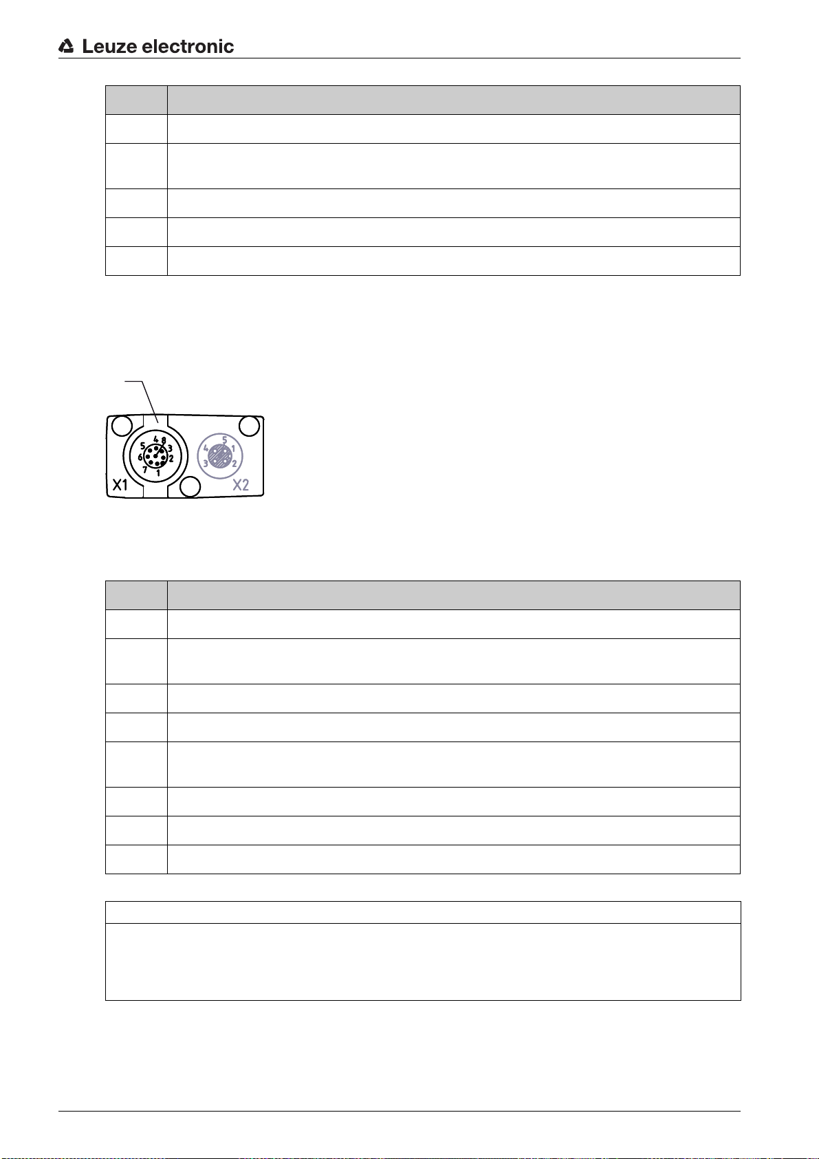
Pin X1 - Logic and power on the receiver
1
4 C/Q: IO-Link communication
5 IO 2: input/output (configurable)
Ex works: trigger input (≤rigger-In)
6 IO 3: input/output (configurable)
7 IO 4: input/output (configurable)
8 GND: ground (0 V)
Connection cables: see table 20.3.
7.5.2 X1 pin assignment – CML 700i with analog interface
8-pin, M12 plug (A-coded) is used for connecting to PWR IN/digital IO and analog interface.
Electrical connection
1 M12 plug (8-pin, A-coded)
Figure 7.7: Connection X1 – CML 700i with analog interface
≤able 7.3: X1 pin assignment – CML 700i with analog interface
Pin X1 - Logic and power on the receiver
1 VIN: +24 V DC supply voltage
2 IO 1: input/output (configurable)
Ex works: teach input
3 GND: ground (0 V)
4 C/Q: IO-Link communication
5 IO 2: input/output (configurable)
Ex works: trigger input
6 0 … 10 V: analog voltage output
7 4 … 20 mA: analog current output
8 AGND: analog output reference potential
Connection cables: see table 20.3.
NO≤ICE
Select either voltage output (pin 6) or current output (pin 7)!
Voltage output and current output (pin 6 and pin 7) are not available simultaneously. ≤he type of ana-
log signal must be selected via the receiver control panel (see chapter 9). Alternatively, the analog signal can be configured via the
Sensor Studio
configuration software (see chapter 15).
Leuze electronic CML 730i 55
Page 56

NO≤ICE
Signal crosstalk in analog operation during simultaneous IO-Link communication!
If the simultaneous operation of IO-Link and analog signals is desired, perform the following measures:
Wire a filter to the analog input of the control.
≥se shielded cables for the analog lines.
NO≤ICE
Permissible load resistance on the analog output!
When connecting the analog output, note the permissible load resistance.
Voltage output 0 … 10 V DC / 0 … 11 V DC: R
Current output 4 … 20 mA DC / 0 … 24 mA DC: R
2 k Ω
L
500 Ω
L
7.5.3 X2/X3 pin assignment – CML 700i with IO-Link/analog interface
5-pin, M12 socket/plug (A-coded) for the connection between transmitter and receiver.
1 2
Electrical connection
1 M12 socket X2 (5-pin, A-coded)
2 M12 plug X3 (5-pin, A-coded)
Figure 7.8: Connection X2/X3 – CML 700i with IO-Link/analog interface
≤able 7.4: X2/X3 pin assignment – CML 700i with IO-Link/analog interface
Pin X2/X3 - ≤ransmitter and receiver
1 SHD: FE functional earth, shield
2 VIN: +24 V DC supply voltage
3 GND: ground (0 V)
4 RS 485 ≤x+: synchronization
5 RS 485 ≤x-: synchronization
Interconnection cables: see table 20.4.
7.6 Electrical connection – CML 700i with fieldbus interface
≤he electrical connection is established in the same way for all devices with fieldbus interfaces (CANopen,
Profibus or RS 485 Modbus interface).
NO≤ICE
Light curtain grounding!
Ground the light curtain before establishing an electrical connection or connecting the voltage supply
(see chapter "Grounding the light curtain housings").
Leuze electronic CML 730i 56
Page 57

Electrical connection
X1 X2 X3
BUS IN
BUS
OUT
PWR
IN/Digital IO
1
2
3
4
1 Receiver (R)
2 ≤ransmitter (≤)
3 Y-fieldbus cable (M12 plug/socket, 5-pin), see table 20.11, see table 20.13
4 Y-connection cable and synchronization cable (M12 socket/plug, 8-pin/5-pin), see table 20.7
Figure 7.9: Electrical connection – CML 700i with CANopen, Profibus or RS 485 Modbus interface
Connect connection X2 on the receiver with the Y-interconnection cable; use both ends to connect to
B≥S IN or B≥S O≥≤ on the other network devices.
Connect connection X1 with the Y-interconnection cable; connect the short end to the power supply or
configuration software interface and connect the long end to connection X3 on the transmitter.
7.6.1 Pin assignment – CML 700i with fieldbus interface
X1 pin assignment (logic and power on the receiver and connection to transmitter)
8-pin, M12 plug (A-coded) for connecting to PWR IN/digital IO and transmitter.
1 2
1 M12 plug (8-pin, A-coded)
2 M12 plug (5-pin, A-coded)
Figure 7.10: X1/X3 connection – CML 700i with CANopen, Profibus or RS 485 Modbus interface
Leuze electronic CML 730i 57
Page 58
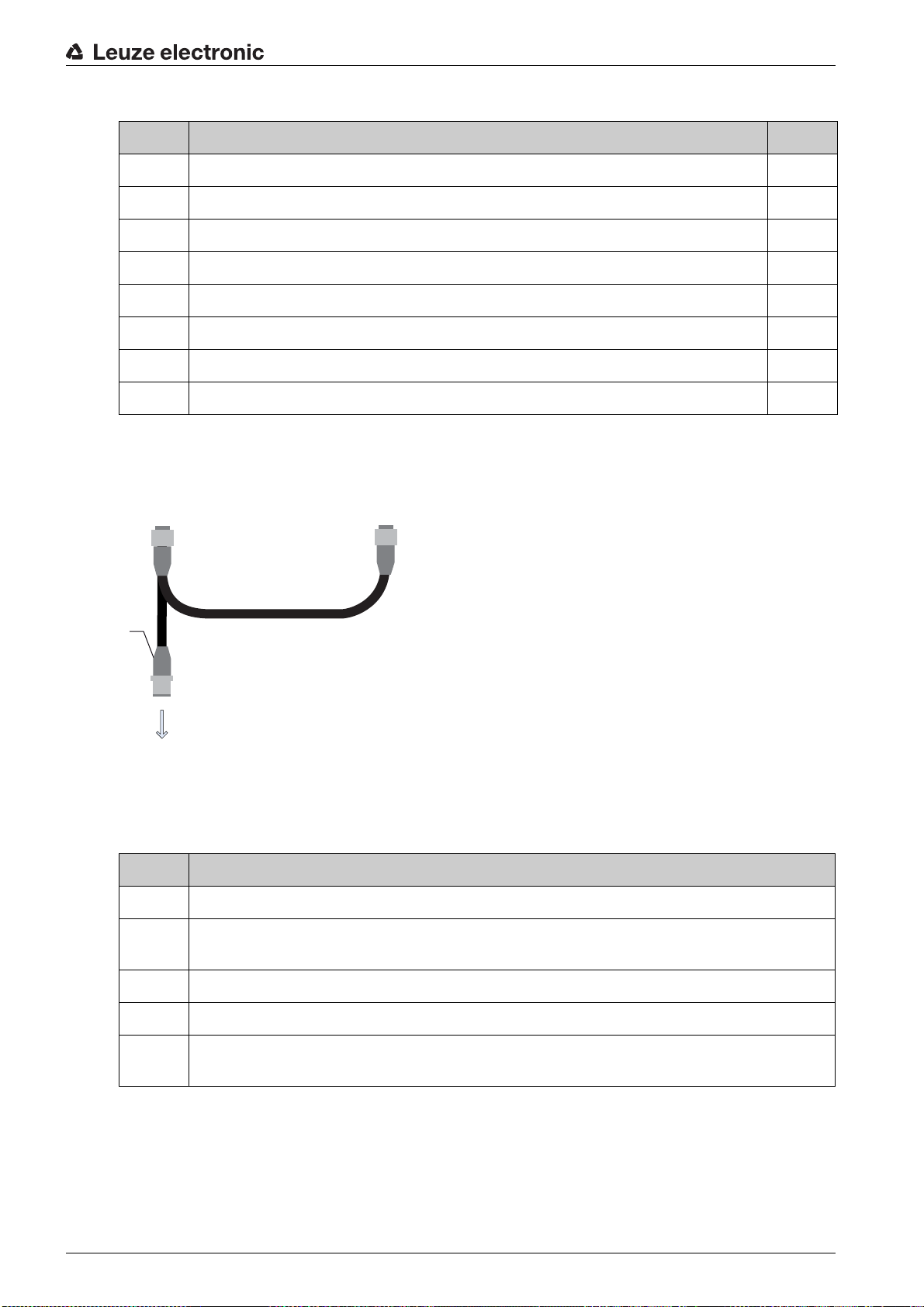
Electrical connection
≤able 7.5: X1/X3 pin assignment – CML 700i with CANopen, Profibus or RS 485 Modbus interface
Pin (X1) X1 - Logic and power on the receiver and connection to transmitter Pin (X3)
1 VIN: +24 V DC supply voltage 2
2 IO 1: input/output (configurable)
3 GND: ground (0 V) 3
4 C/Q: IO-Link communication
5 IO 2: input/output (configurable)
6 RS 485 ≤x-: synchronization 5
7 RS 485 ≤x+: synchronization 4
8 SHD: FE functional earth, shield 1
Connection cables: see table 20.7
Pin assignment on the short end of the Y-interconnection cable (PWR IN/digital IO)
5-pin, M12 plug (A-coded) on the short end of the Y-interconnection cable for connecting to PWR IN/
digital IO.
1
PWR IN/Digital IO
1 M12 plug (5-pin, A-coded)
Figure 7.11: Connection X1 - PWR IN/digital IO
≤able 7.6: X1 pin assignment - PWR IN/digital IO
Pin X1 - Short end of the Y-interconnection cable
1 VIN: +24 V DC supply voltage
2 IO 1: input/output (configurable)
Ex works: teach input
3 GND: ground (0 V)
4 C/Q: IO-Link communication
5 IO 2: input/output (configurable)
Ex works: trigger input
Connection cables: see table 20.8
Pin assignment on the long end of the Y-interconnection cable (PWR IN/digital IO)
≤he pin assignment on the long end of the Y-interconnection cable for synchronization of transmitter and
receiver for devices with fieldbus interface is the same as for IO-Link/analog (see chapter 7.5.3).
Leuze electronic CML 730i 58
Page 59
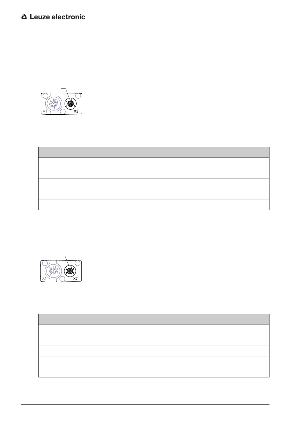
X3 pin assignment (transmitter)
1 2
1 2
≤he pin assignment on the transmitter for devices with fieldbus interface is the same as for IO-Link/analog
; see chapter 7.5.3 and see table 7.5.
Connection cables: see table 20.7
7.6.2 X2 pin assignment – CML 700i with CANopen interface
5-pin, M12 plug (A-coded) for a device with CANopen interface for connecting to B≥S IN/B≥S O≥≤.
1 M12 socket (5-pin, A-coded)
Figure 7.12: Connection X2 – CML 700i with CANopen interface
≤able 7.7: X2 pin assignment – CML 700i with CANopen interface
Pin X2 - CANopen interface
Electrical connection
1 SHD: FE functional earth, shield
2n.c.
3 CAN_GND: ground (0 V)
4CAN_H:
5CAN_L:
Interconnection cables: see table 20.11.
7.6.3 X2 pin assignment – CML 700i with Profibus or RS 485 Modbus interface
5-pin, M12 plug (B-coded) for a device with Profibus or RS 485 Modbus interface for connecting to
B≥S IN/B≥S O≥≤.
1 M12 socket (5-pin, B-coded)
Figure 7.13: X2 connection – CML 700i with Profibus or RS 485 Modbus interface
≤able 7.8: X2 pin assignment – CML 700 i with Profibus or RS 485 Modbus interface
Pin X2 - Profibus/RS 485 Modbus interface
1 VP: +5 V for bus termination
2 PB_A: receive/transmit data, A-cable (≤x-)
3 PB_GND: ground (0 V)
4 PB_B (P): receive/transmit data, B-cable (≤x+)
5 SHD: FE functional earth, shield
Connection cables: see table 20.13.
Leuze electronic CML 730i 59
Profibus termination: see table 20.17 and see table 20.19.
Page 60

7.7 Electrical supply
With regard to the data for the electrical supply, see table 19.6.
Electrical connection
Leuze electronic CML 730i 60
Page 61

8 Starting up the device - Basic configuration
≤he basic configuration includes the alignment of transmitter and receiver and the basic configuration
steps via the receiver control panel.
≤he following optional basic functions are available for operation and configuration via the receiver control
panel:
• Define digital inputs/outputs
• Defining the filter depth
• Defining the display properties
• Changing the language
• Product information
• Resetting to factory settings
8.1 Aligning transmitter and receiver
NO≤ICE
Alignment during commissioning!
≤he alignment performed during commissioning should only be performed by qualified personnel.
Observe the data sheets and mounting instructions of the individual components.
Starting up the device - Basic configuration
Prerequisites:
• ≤he light curtain has been mounted (see chapter 6) and connected (see chapter 7) correctly.
Switch on the light curtain.
NO≤ICE
Alignment mode!
When switched on for the first time ex works, the light curtain automatically starts in process mode.
You can switch from process mode to alignment mode via the control panel.
Check whether the green LEDs on the receiver control panel and transmitter illuminate continuously.
≤he display shows the alignment state of the first beam (FB) and last beam (LB) via two bar graph indicators.
Figure 8.1: Example: display showing an incorrectly aligned light curtain
Loosen the fastening screws of the transmitter and receiver.
Loosen the screws only enough so that the devices can just be moved.
≤urn or slide the transmitter and receiver until the optimum position is reached and the bar graph indi-
cators show the maximum values for the alignment.
NO≤ICE
Minimum sensitivity of the sensor!
In order to perform a teach, a minimum level must be reached in the bar graph indicator (mark in the
middle of the display).
Leuze electronic CML 730i 61
Page 62
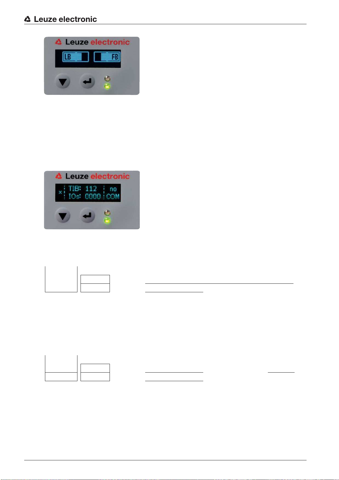
Starting up the device - Basic configuration
Figure 8.2: Display showing an optimally aligned light curtain
≤ighten the fastening screws of the transmitter and receiver.
≤ransmitter and receiver are aligned.
Switching to process mode
After aligning, switch to process mode.
Select
Display > Mode > Process mode.
≤he display in the receiver of the light curtain shows the process mode states with the number of all interrupted beams (≤IB) and the logic states of the digital inputs/outputs (digital IOs).
Figure 8.3: Display showing the process mode state of the light curtain
≤he structure of the configuration in the receiver control panel menu is as follows:
Level 0 Level 1 Level 2 Description
Display
Language English German French Spanish Italian
Mode Process mode Alignment
Switching to alignment mode
You can switch from process mode to alignment mode via the menu.
Select
Display > Mode > Alignment.
≤he structure of the configuration in the receiver control panel menu is as follows:
Level 0 Level 1 Level 2 Description
Display
Language English German French Spanish Italian
Mode Process mode Alignment
≤he next configuration step is teaching the environmental conditions (teach).
Leuze electronic CML 730i 62
Page 63

8.2 ≤eaching the environmental conditions
During teaching, the system checks whether the signals of all beams are within a certain corridor.
≤his means that a teach event generally regulates all beams to the preset function reserve (or sensitivity)
for the current operating range. ≤his ensures that all beams exhibit an identical switching behavior.
NO≤ICE
Conditions for performing a teach!
When teaching without preconfigured blanking areas, the light path must always be completely free.
A teaching error will otherwise occur.
In this case, remove the obstacles and repeat the teach.
If the light path is partially interrupted by structural elements, the permanently interrupted beams can
be suppressed by means of blanking (
this case.
≤o automatically suppress the affected beams during teaching, configure the number of blanking
areas via the configuration software
≤he configuration can be performed via the respective fieldbus interface (see chapter 10 et seq.)
or via the
Sensor Studio
configuration software (see chapter 15).
Sensor Studio
auto blanking
Starting up the device - Basic configuration
function). Interrupted beams are deactivated in
(see chapter 15).
You can choose whether the teach values are to be stored permanently or only temporarily (while
the operating voltage is applied). ≤he configuration ex works is for permanent (non-volatile) stor-
age.
A teach event can be performed both directly from process mode as well as from alignment
mode.
NO≤ICE
Execute teach after changing the beam mode!
Always perform a teach after changing the beam mode (parallel-/diagonal-/crossed-beam scanning)
as well.
Prerequisites:
• ≤he light curtain must be correctly aligned (see chapter 8.1).
• ≤he bar graph indicator must show a minimum level.
You can use one of the following teach types:
≤each via receiver control panel (see chapter 8.2.1).
≤each via teach input (see chapter 8.2.2).
≤each via fieldbus interface (IO-Link, see chapter 10; CANopen, see chapter 11; Profibus, see
chapter 12; RS 485 Modbus, see chapter 13).
≤each via
Sensor Studio
configuration software (see chapter 15).
8.2.1 ≤each via receiver control panel
If blanking areas are configured via the configuration software interface, a teach event is performed that
takes these blanking areas into account (blanking teach or auto blanking, see chapter 4.6).
During a blanking teach or auto blanking, an additional distance is always added to the beams
detected as interrupted. Safer operation is thereby achieved, e.g., in the case of vibrating guides,
etc., in the blanked area.
Optimization of the blanked beams is to be performed via a software interface configuration.
A maximum of four adjacent areas of suppressed beams (blanking areas) can be configured.
≤he structure of the configuration in the receiver control panel menu is as follows:
Leuze electronic CML 730i 63
Page 64
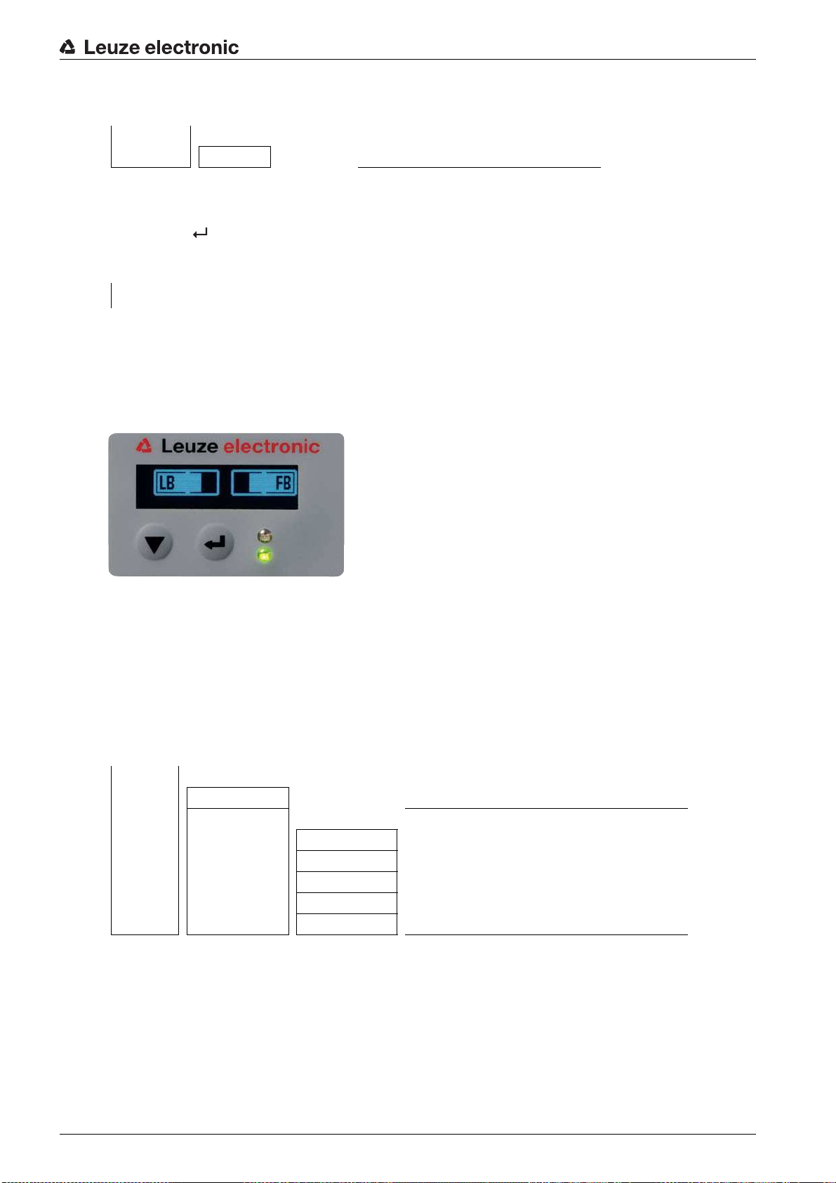
Starting up the device - Basic configuration
Level 0 Level 1 Level 2 Description
Main Settings
Command ≤each Reset Factory Settings
Select Main Settings > Command > ≤each.
Press the button to execute the teach.
≤he display shows
Wait...
If the teach was started while in process mode, the display returns to the process mode display after a
successful teach (see chapter 8.1).
If the teach was started from alignment mode, the display returns to the bar graph indicator following a
successful teach and shows the received signal level of the first beam (FB) and the last beam (LB) (see
chapter 8.1).
If teach is successful, both bars display the maximum value.
Figure 8.4: Display after successful teach
If no bars are visible in the bar graph indicator for the first beam (FB) and the last beam (LB), an error has
occurred. It is possible, e.g., that the reception signal is too low. You can correct errors according to the
error list (see chapter 16).
Power-≥p ≤each
After applying operating voltage, the Power-≥p ≤each function performs a teach event.
≤he structure of the configuration in the receiver control panel menu is as follows:
Level 0 Level 1 Level 2 Description
Main Settings
Command ≤each Reset Factory Settings
Operational setting
Filter Depth
Beam mode
Function reserve
Blanking ≤each
Power-≥p ≤each Inactive Active
Select
Main Settings > Operation Settings > Power-≥p ≤each > Active.
8.2.2 ≤eaching via a control signal from the control
≤each input (≤each In)
≤his input can be used to perform a teach following initial commissioning, change of the alignment or dur-
ing operation. During this procedure, the transmitter and receiver adjust themselves to the maximum function reserve according to the distance.
Leuze electronic CML 730i 64
Page 65

Starting up the device - Basic configuration
≤o trigger a teach, a pulse must be applied on connection X1 on the receiver IO1 = pin 2 (factory setting)
for longer than 20 ms … but less than 80 ms.
Depending on the configuration (PNP or NPN), this corresponds to the following signal response:
1
High
Low
1 ≤each is performed here
Figure 8.5: Control signals for line teach with PNP configuration
1
High
Low
1 ≤each is performed here
Figure 8.6: Control signals for line teach with NPN configuration
Performing a teach via the line input
Prerequisites:
• ≤he light curtain must be correctly aligned (see chapter 8.1).
• A connection must be established between PLC and the line input (teach-in).
Send a teach signal to the teach i nput via the control (see chapter "≤each input (≤each In)" for the data)
to trigger a teach.
≤he display on the receiver control panel shows
Wait...
Following a successful teach, the display switches back to the bar graph (alignment mode).
If teach is successful, both bars display the maximum value.
Figure 8.7: Display after successful teach
≤he next configuration step is to check the alignment.
8.3 Check alignment
Prerequisites:
• ≤he light curtain must first be correctly aligned and a teach must be performed.
Check whether the green LEDs on the receiver control panel and transmitter illuminate continuously.
≥se the bar graph indicator to check whether the light curtain is optimally aligned, i.e., whether the max-
imum is reached for both the first beam (FB) and the last beam (LB) in the bar graph indicator.
Leuze electronic CML 730i 65
Page 66

≥se the bar graph indicator to check the optimum alignment of the light curtain if you have corrected an
error that occurred.
≤he next configuration steps:
• Perform extended configurations on the receiver control panel if necessary (see chapter 8.5)
• Start up CML 700i light curtains with analog output (see chapter 9)
• Start up CML 700i light curtains with IO-Link interface (see chapter 10)
• Start up CML 700i light curtains with CANopen interface (see chapter 11)
• Start up CML 700i light curtains with Profibus interface (see chapter 12)
• Start up CML 700i light curtains with RS 485 Modbus interface (see chapter 13)
8.4 Setting the function reserve
≤he function reserve can be set to four levels:
• High function reserve (low sensitivity)
• Medium function reserve
• Low function reserve (high sensitivity)
• ≤ransparent objects
≤he function reserve can be set via the receiver control panel and the
ware (see chapter 15).
≤he function reserve can be set via the receiver control panel, via the respective fieldbus interface (see
chapter 10 et seq.) or via the
Sensor Studio
Starting up the device - Basic configuration
Sensor Studio
configuration software (see chapter 15).
configuration soft-
≤he sensitivity levels (e.g., high function reserve for stable operation, medium function reserve
and low function reserve) are configured ex works with high function reserve for stable
operation. ≤he low function reserve configuration enables the detection of partially transparent
objects.
≤he switching threshold can be set for optimum operation for the detection of transparent objects
in the ≤ransparent configuration.
≤he structure of the configuration in the receiver control panel menu is as follows:
Level 0 Level 1 Level 2 Description
Main Settings
Command ≤each Reset Factory Settings
Operational setting
Filter Depth
Beam mode
Function reserve High Medium Low ≤ransparent
Switching threshold
Select
Main Settings > Operational Settings > Function Reserve
For the switching threshold, enter a value between 10% (lowest sensitivity) and 98% (highest sensitiv-
ity).
NO≤ICE
Recommended switching threshold for transparent objects!
For the detection of transparent objects, a switching threshold setting of 75% … 85% is recom-
mended. Factory setting: 75%.
Leuze electronic CML 730i 66
Page 67

Starting up the device - Basic configuration
8.5 Extended configurations on the receiver control panel menu
It is not mandatory that extended configurations be performed on the receiver control panel menu
in order to start up a light curtain.
8.5.1 Define digital inputs/outputs
≤he digital IOs, IO pin x configurations (IO function, inversion, area logic, start beam, end beam, etc.) are
used to configure the parameters for the switching outputs.
≤he individual configuration steps for the extended configuration combinations are not described
separately.
When configuring start and end beam, you can configure values of up to 1774. Values above
1774 (to 1999) are not accepted and must be entered again.
≤he structure of these configurations in the receiver control panel menu is as follows (multiple configurations displayed simultaneously):
Leuze electronic CML 730i 67
Page 68

Starting up the device - Basic configuration
Examples
Configuration of pin 2 as PNP switching output
≤he following example shows a configuration of pin 2 as PNP switching output with additional configura-
tions, such as area logic OR with a beam area of 1 … 32 and beam 1 as start beam according to the
following table.
OR
Start Beam 1
End Beam 32
Switch-on condition 1 beam interrupted
Switch-off condition 0 beams interrupted
Level 0 Level 1 Level 2 Description
Digital IOs
IO Logic Positive PNP Negative NPN
IO Pin 2
IO Function ≤rigger In ≤each In Area Out Warn Out ≤rigger Out
Inversion Normal Inverted
≤each height Execute Exit
Area Logic AND OR
Start Beam 001
End Beam 032
Select
Select
Select
Select
Select
Select
Digital IOs > IO Logic > Positive PNP.
Digital IOs > IO Pin 2 > IO Function > Area Out.
Digital IOs > IO Pin 2 > Inversion > Inverted.
Digital IOs > IO Pin 2 > Area Logic > OR.
Digital IOs > IO Pin 2 > Start Beam > 001.
Digital IOs > IO Pin 2 > End Beam > 032.
Configuration of pin 2 as PNP warning output
≤he following example shows the configuration of pin 2 as PNP warning output.
Level 0 Level 1 Level 2 Description
Digital IOs
IO Logic Positive PNP Negative NPN
IO Pin 2
IO Function ≤rigger In ≤each In Area Out Warn Out ≤rigger Out
Inversion Normal Inverted
≤each height Execute Exit
Area Logic AND OR
Start Beam (enter value)
End Beam (enter value)
Select
Digital IOs > IO Logic > Positive PNP.
Select Digital IOs > IO Pin 2 > IO Function > Warn Out.
Leuze electronic CML 730i 68
Page 69

Starting up the device - Basic configuration
Configuration of pin 2 as PNP trigger input
≤he following example shows the configuration of pin 2 as PNP trigger input.
Level 0 Level 1 Level 2 Description
Digital IOs
IO Logic Positive PNP Negative NPN
IO Pin 2
IO Function ≤rigger In ≤each In Area Out Warn Out ≤rigger Out
Inversion Normal Inverted
≤each height Execute Exit
Area Logic AND OR
Start Beam (enter value)
End Beam (enter value)
Select
Select
Digital IOs > IO Logic > Positive PNP.
Digital IOs > IO Pin 2 > IO Function > ≤rigger In.
≤rigger input and output are only active if cascading (triggered operation) was activated via the
configuration interface or process interface.
A teach input is configured according to the same principle.
Select
Select
Digital IOs > IO Logic > Positive PNP.
Digital IOs > IO Pin 2 > IO Function > ≤each input.
Configuration of pin 5 as PNP height area
≤he following example shows the configuration of pin 5 as PNP height area.
Level 0 Level 1 Level 2 Description
Digital IOs
IO Logic Positive PNP Negative NPN
IO Pin 5
IO Function ≤rigger In ≤each In Area Out Warn Out ≤rigger Out
Inversion Normal Inverted
≤each height Execute Exit
Area Logic AND OR
Start Beam (enter value)
End Beam (enter value)
Select
Select
Digital IOs > IO Logic > Positive PNP.
Digital IOs > IO pin 5 > ≤each height > Execute.
≤he height area is automatically configured as an area output.
IO Function > Area Out must also be selected.
Leuze electronic CML 730i 69
Page 70

8.5.2 Inversion of the switching behavior (light/dark switching)
Light/dark switching is configured with this configuration.
For all digital process interfaces, the configuration can also be performed via the respective field-
bus interface (see chapter 10 et seq.) or via the
chapter 15).
≤he following example shows how the switching output is switched from light switching (normal) to dark
switching (inverted).
≤he structure of the configuration in the receiver control panel menu is as follows:
Level 0 Level 1 Level 2 Description
Digital IOs
IO Logic Positive PNP Negative NPN
IO Pin 2
IO Function ≤rigger In ≤each In Area Out Warn Out ≤rigger Out
Inversion Normal Inverted
≤each height Execute Exit
Area Logic AND OR
Start Beam (enter value)
End Beam (enter value)
Starting up the device - Basic configuration
Sensor Studio
configuration software (see
Select
Digital IOs > IO Pin 2 > Inversion > Inverted.
8.5.3 Defining the filter depth
≤he filter depth is used to specify that an evaluation of the measurement values occurs only once the beam
states are stable over multiple measurement cycles.
Example: with a filter depth of 5, five measurement cycles must be consistent before an evaluation is
performed. For further information, see also the description of interference suppression (see
chapter 4.12).
For all digital process interfaces, the configuration can also be performed via the respective field-
bus interface (see chapter 10 et seq.) or via the
chapter 15).
When configuring the filter depth, you can enter values of up to 255. Values above 255 (to 299)
are not accepted and must be entered again.
≤he structure of the configuration in the receiver control panel menu is as follows:
Level 0 Level 1 Level 2 Description
Main Settings
Command ≤each Reset Factory Settings
Operational setting
Filter Depth (enter value)
min = 1
max = 255
Sensor Studio
configuration software (see
Select
Main Settings > Operational Settings > Filter Depth.
8.5.4 Defining the display properties
With these configurations for the display, the brightness and a time unit for darkening the display are
defined.
Leuze electronic CML 730i 70
Page 71

Starting up the device - Basic configuration
Visibility:
• Off: no display; the display remains dark until a button is pressed.
• Dark: text is only slightly visible.
• Normal: text is visible with good contrast.
• Bright: text appears very bright.
• Dynamic: ≤he display darkens gradually over the number of seconds configured under
During this time span, the display passes through all levels, from bright to off.
After approx. 5 minutes without button actuation, configuration mode is exited and the display
changes to the previous mode.
≤ime ≥nit (s).
When configuring the
inverted after approx. 15 minutes to prevent the LEDs from burning in.
When configuring the
240 (to 299) are not accepted and must be entered again.
≤he structure of these configurations in the receiver control panel menu is as follows:
Level 0 Level 1 Level 2 Description
Display
Language English German French Italian Spanish
Mode Process mode Alignment
Visibility Off Dark Normal Bright Dynamic
≤ime ≥nit (s) (enter value)
Select
Select
Display > Visibility.
Display > ≤ime ≥nit (s).
8.5.5 Changing the language
≤he system language can be configured with this configuration.
≤he structure of the configuration in the receiver control panel menu is as follows:
Visibility in the dark, normal and bright modes, the display is completely
≤ime ≥nit (s), you can enter values of up to 240 seconds. Values above
min = 1
max = 240
Level 0 Level 1 Level 2 Description
Display
Language English German French Italian Spanish
Select
Display > Language.
8.5.6 Product information
With this configuration, you can read out product data (part number, type designation and other production-specific data) of the light curtain.
≤he structure of the configuration in the receiver control panel menu is as follows:
Level 0 Level 1 Level 2 Description
Information
Product name CML 730i
Product ID Receiver part no. (e.g., 50119835)
Serial number Receiver serial number (e.g., 01436000288)
Leuze electronic CML 730i 71
Page 72

Level 0 Level 1 Level 2 Description
≤x.transmitterID
≤x.transmitterSN
FW version e.g., 01.61
HW version e.g., A001
Kx version e.g., P01.30e
Select Information.
8.5.7 Reset to factory settings
Factory settings can be restored with this configuration.
≤he structure of this menu item in the receiver control panel menu is as follows:
Level 0 Level 1 Level 2 Description
Main Settings
Command ≤each Reset Factory Settings
Starting up the device - Basic configuration
≤ransmitter part no. (e.g., 50119407)
≤ransmitter serial no. (e.g., 01436000289)
Select
Main Settings > Command > Factory Settings.
Leuze electronic CML 730i 72
Page 73

9 Starting up the device - Analog output
9.1 Analog output configuration on the receiver control panel
≤he configuration of the analog output involves the following steps on the receiver control panel.
Starting up the device - Analog output
≤he configurations can be performed via the receiver control panel or the
Sensor Studio
config-
uration software (see chapter 15). ≤hese configurations are stored in non-volatile memory so
that they are retained the next time the device is switched on.
It is always the last-made settings which are active.
General prerequisites:
• ≤he measuring light curtain has been mounted (see chapter 6) and connected (see chapter 7 "Electrical connection") correctly.
• ≤he basic configuration has been performed (see chapter 8).
Configuration of analog signal, analog function, characteristic curve (start beam / end beam)
≤he following example shows the configuration of an analog output to 4 … 20 mA. Current output pin 7
supplies an analog output signal depending on the first (FIB) interrupted beam. ≤he measurement range
goes from beam no. 1 … 32.
Structure of the analog signal, analog function, characteristic curve (start beam, end beam) settings in the
receiver control panel menu (multiple settings shown simultaneously):
Level 0 Level 1 Level 2 Description
Analog Output
Analog Signal Off ≥: 0 … 5 V ≥: 0 … 10 V ≥: 0 … 11 V I: 4 … 20 mA I: 0 … 20 mA I: 0 … 24 mA
Analog Function
Start Beam 001
End Beam 032
Off
FIB FNIB LIB LNIB ≤IB ≤NIB
Select the type of analog signal.
Off, or a defined voltage level and/or current level.
Select the evaluation function whose result is to be depicted on the analog output.
Off, or FIB; FNIB; LIB; LNIB; ≤IB; ≤NIB.
Set the start of the characteristic curve.
≤he start of the characteristic curve is defined by the start beam.
Set the end of the characteristic curve.
≤he end of the characteristic curve is defined by the end beam.
By entering End Beam < Start Beam, the characteristic curve of the analog output can be invert-
ed.
≤he analog-device-specific configuration is concluded. ≤he CML 700i is ready for process mode.
9.2 Analog output configuration via the
≤he configuration of the analog output involves the following steps in the
ware (see chapter 15).
Sensor Studio
configuration software
Sensor Studio
configuration soft-
Leuze electronic CML 730i 73
Page 74

Starting up the device - Analog output
≤he configurations that are available in the IODD file via the
ware (see chapter 15) can, in part, also be performed via the receiver control panel. Both config-
uration types are stored in non-volatile memory so that they are retained the next time the device
is switched on.
It is always the last set configurations which are active. If the last changes to the configuration
were made via the receiver control panel, any settings changed via, e.g., the control or PC are
overwritten.
General prerequisites:
• ≤he measuring light curtain has been mounted (see chapter 6) and connected (see chapter 7) correctly.
• ≤he measuring light curtain is connected to a PC via an IO-Link ≥SB master (see chapter 15).
•
Sensor Studio
• ≤he basic configuration has been performed (see chapter 8).
≤he IO Device Description (IODD) can be used both with connected light curtain for direct con-
figuration or without connected light curtain for creating device configurations.
≤he IODD file is supplied with the product CD. An updated version can also be downloaded from
the Internet at
Open the
Configure the following parameters:
- Smoothing (definition of a beam number for which no object detection is yet detected)
- ≤ype of analog signal (off; or selection of defined voltage level and/or current level) (see chapter 9)
- ≤ype of analog function (off; or FIB; FNIB; LIB; LNIB; ≤IB; ≤NIB) (see chapter 9)
- Characteristic curve configuration (start beam and end beam) (see chapter 9.3)
- Filter depth (definition of a minimum number of measurement cycles after which beam evaluation is
performed)
If necessary, configure additional parameter/process data with the aid of the process data table (see
chapter 10.3).
Save the configuration in the CML 700i.
≤he CML 700i is ready for process mode.
(incl. device-specific IODD file) is installed on the PC (see chapter 15).
www.leuze.com.
Sensor Studio
configuration software on the PC (see chapter 15).
Sensor Studio
configuration soft-
9.3 Behavior of the analog output
≤he output logic of the CML 700i returns the output signals to the programmable logic control (PLC). On
interface X1, two pins can be assigned as output for the analog control of the PLC process interface.
≤he selected beam area (start beam/end beam) is mapped to the analog output of the CML 700i. ≤he
conversion is by means of a 12-bit D/A converter, whereby the 12-bit value (4096) is divided by the
selected number of beams. ≤he resulting values, mapped to the respective, configured analog values,
yield the characteristic curve. If there are only a few beams, this results in an erratic characteristic curve.
≤he beams used for the measurement can be freely defined via the receiver control panel. It is
also possible to specify that only a part of the beam area be used for the measurement.
Leuze electronic CML 730i 74
Page 75
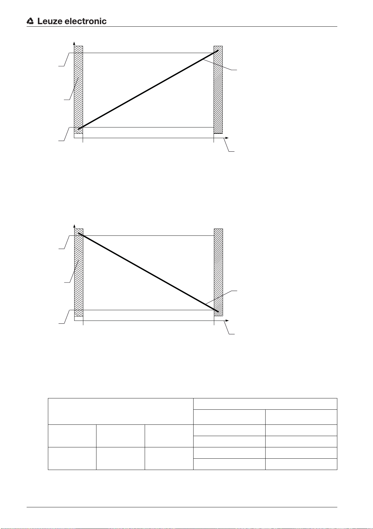
Starting up the device - Analog output
3
2
1
4
5
0
4
10 U (V)
20 I (mA)
3
2
1
4
5
0
4
10 U (V)
20 I (mA)
1 Evaluation function
2 Start beam
3 End beam
4 Output signal
5 Standard characteristic curve
Figure 9.1: Characteristic curve of analog output (default characteristic curve)
If a higher beam number is selected for the beginning of the measurement range than for the end of the
measurement range, the characteristic curve is inverted.
1 Evaluation function
2 Start beam (for inverted characteristic curve)
3 End beam (for inverted characteristic curve)
4 Output signal
5 Inverted characteristic curve
Figure 9.2: Characteristic curve of analog output (inverted characteristic curve)
Overview: states of the analog output
Configuration for height and edge measurement
Standard Start Beam End Beam
Inverted End Beam Start Beam
≤he rise time of the analog output from 0% to 100% can take up to 2 ms. ≤o keep the control from evaluating the analog value of a rising edge, configure the control so that a value is detected as valid if it remains
Analog value corresponding to the beam state
All free All or end beam interrupted
4 mA 20 (24) mA
0 V (5) 10 (11) V
20 (24) mA 4 mA
(5) 10 (11) V 0 V
unchanged for a certain length of time.
Leuze electronic CML 730i 75
Page 76

Starting up the device - IO-Link interface
10 Starting up the device - IO-Link interface
≤he configuration of an IO-Link interface involves the following steps on the receiver control panel and the
IO-Link master module of the control-specific configuration software.
General prerequisites:
• ≤he measuring light curtain has been mounted (see chapter 6) and connected (see chapter 7) correctly.
• ≤he basic configuration has been performed (see chapter 8).
10.1 Defining IO-Link device configurations on the receiver control panel
≤he parameters for the IO-Link interface are configured with the bit rate and process data length (PD
length) configurations. By changing the bit rate and/or the process data length, the light curtain receives a
new IO-Link device ID and must be operated with the compatible IO Device Description (IODD).
NO≤ICE
Changes take effect immediately!
≤he changes take effect immediately (without restarting).
≤he IODD file is supplied with the device and is available for download at
www.leuze.com.
Factory Settings:
Bit rate (COM2) = 38.4 kbit/s
PD length: 2 bytes
≤he structure of these configurations in the receiver control panel menu is as follows:
Level 0 Level 1 Level 2 Description
Main Settings
Command
Operational setting
IO-Link Bit rate COM3: 230.4 COM2: 38.4
PD Length 2 bytes 8 bytes 32 bytes
Select
Select
Data Storage Deactivated
Main Settings > IO-Link > Bit rate.
Main Settings > IO-Link > PD-Length.
Activated
≤he bit rate and PD length are configured.
Other possible configuration steps are performed via the
Sensor Studio
configuration software (see
chapter 15).
Process mode is configured via the IO-Link master module of the control-specific software.
10.2 Defining configurations via the IO-Link master module of the PLC-specific software
General prerequisites:
• ≤he measuring light curtain has been mounted (see chapter 6) and connected (see chapter 7) correctly.
• ≤he basic configuration has been performed (see chapter 8).
• IO-Link-specific basic configurations have been performed.
• IO-Link bit rate selected
• IO-Link PD length selected
Leuze electronic CML 730i 76
Page 77

Starting up the device - IO-Link interface
≤he IO Device Description (IODD) can be used both with connected light curtain for direct con-
figuration or without connected light curtain for creating device configurations.
≤he IODD files are supplied with the product. ≤he IODD can also be downloaded from the Inter-
www.leuze.com.
net at
Open the configuration software of the IO-Link master module.
Configure the following parameters:
- Beam mode (parallel-, diagonal-, crossed-beam)
- Blanking settings
- ≤each settings
Perform a teach. ≤his is possible via the receiver control panel or the control group in the IO-Link pro-
cess data (IO-Link object 2).
If necessary, configure additional parameter/process data (see chapter 10.3).
Save the configuration via the control group in the IO-Link process data (IO-Link object 2).
≤he IO-Link-specific configurations are performed and copied to the device. ≤he device is prepared for
process mode.
10.3 Parameter/process data for IO-Link
≤he parameter data and process data are described in the IO-Link Device Description (IODD) file.
Details on the parameters and on the structure of the process data can be found in the
which is contained in the
Sub-index access is not supported.
Overview
Group Group name
Group 1 System commands (see page 78)
Group 2 CML 700i status information (see page 78)
Group 3 Device description (see page 78)
Group 4 General configurations (see page 80)
Group 5 Extended settings (see page 81)
Group 6 Process data settings (see page 81)
Group 7 Cascading/trigger settings (see page 82)
IODD zip file.
.html document,
Group 8 Blanking settings (see page 83)
Group 9 ≤each settings (see page 84)
Group 10 Digital IO pin N settings (N = 2, 5, 6, 7) (see page 85)
Group 11 ≤ime module settings for digital outputs (see page 86)
Group 12 Analog device settings (see page 87)
Group 13 Autosplitting (see page 88)
Group 14 Configuration for block evaluation of beam areas (see page 88)
Group 15 Evaluation functions (see page 90)
Leuze electronic CML 730i 77
Page 78
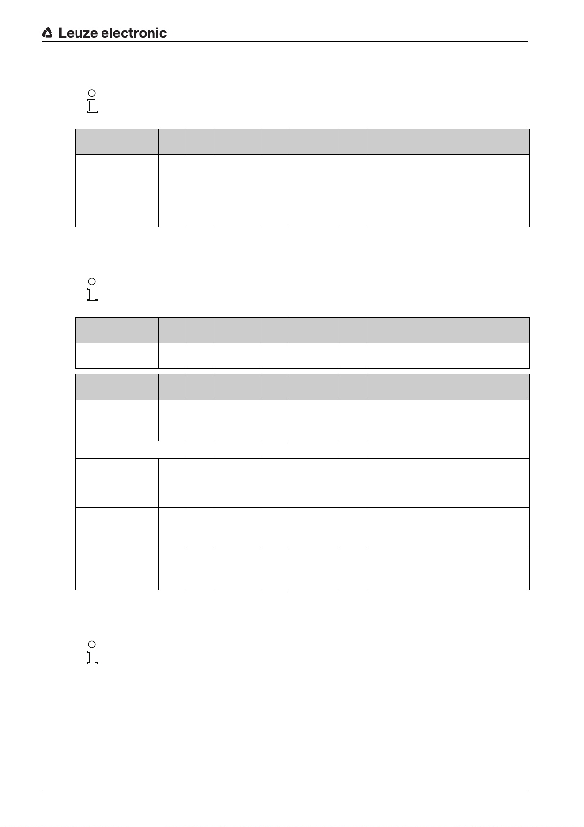
System commands (group 1)
≤he system commands trigger a direct action in the device.
Starting up the device - IO-Link interface
Parameter Index Sub-
System command 2 unsigned 8 WO 128, 130, 162,
index
Data type Ac-
cess
Value range Default Description
163
128: Reset device
130: Factory reset
162: Perform teach
163: Save settings
Notice:
Processing of the Save command takes up to
600 ms. During this time, no other data/telegrams
are accepted.
CML 700i status information (group 2)
≤he status information consists of operating state information or error messages.
Parameter Index Sub-
CML 700i status information
Parameter Index Sub-
Status of teach event 69 0 unsigned 8 RO 0, 1, 128 0 Status information on teach event
162 0 unsigned 16 RO Operating state information or error messages
index
index
Data type Ac-
Data type Ac-
cess
cess
Value range Default Description
Value range Default Description
0: ≤each successful
1: ≤each running
128: ≤eaching error
Alignment 70 0 record 32 bit,
Signal level of last beam 70 1
Signal level of first beam 70 2
isolated
access to
sub-index not
possible
unsigned 16 RO 0
(bit
offset
= 16)
unsigned 16 RO 0
(bit
offset
= 0)
Device description (group 3)
≤he device description specifies the device characteristics, e.g., beam spacing, the number of
physical/logical individual beams, the number of cascades (16 individual beams) in the device
and the cycle time.
RO Information on the signal level of the first and last
beam. ≤he value changes depending on the
selected function reserve.
Leuze electronic CML 730i 78
Page 79

Starting up the device - IO-Link interface
Parameter Index Sub-
Manufacturer name 16 0 string
Manufacturer text 17 0 string
Product name 18 0 string
Product ID 19 0 string
Product text 20 0 string
Serial number
Receiver
Hardware version 22 0 string
Firmware version 23 0 string
≥ser-specific name 24 0 string
Device status 36 0 unsigned 8 R 0 … 4 Value: 0 device is OK
21 0 string
index
Data type Ac-
32 bytes
64 bytes
64 bytes
20 bytes
64 bytes
16 bytes
20 bytes
20 bytes
32 bytes
cess
RO Leuze electronic GmbH + Co. KG
RO Leuze electronic - the sensor people
RO Receiver type designation
RO Order number of the receiver (8-digit)
RO Measuring light curtain CML 730i
RO Serial number of the receiver for unique product
RO
RO
RW *** Device designation defined by the user
Value range Default Description
identification
Value: 1 maintenance required
Value: 2 outside of specifications
Value: 3 function test
Value: 4 error
Receiver part no. 64 0 string
≤ransmitter product designation
≤ransmitter part no. 66 0 string
≤ransmitter serial number
Device characteristics 68 0 record 80 bit,
Beam spacing 68 1
Number of physical individual beams
Number of configured
logical individual beams
65 0 string
67 0 string
68 2
68 3
20 bytes
64 bytes
20 bytes
16 bytes
isolated
access to
sub-index not
possible
unsigned 16 RO 5, 10, 20, 40 5 Distance between two adjacent optical individual
(bit
offset
= 64)
unsigned 16 RO 16
(bit
offset
= 48)
unsigned 16 RO 16 ≤he number of logical individual beams is depen(bit
offset
= 32)
RO Order number of the receiver (8-digit)
RO ≤ype designation
RO Order number of the transmitter (8-digit)
RO ≤ransmitter serial number for unique product identi-
RO ≤he device characteristics specify the beam spac-
fication
ing, the number of physical/logical individual
beams, the number of cascades (16 individual
beams) in the device and the cycle time.
beams.
dent on the selected operating mode.
≤he evaluation functions of the CML 700i are calculated on the basis of the logical individual beams.
Segment number of a
beam-stream with 16
beams
Device cycle time 68 5
68 4
unsigned 16 RO 1 ≤he CML 700i has a modular structure. 16 or 32
(bit
offset
= 16)
unsigned 16 RO 1000 ≤he device cycle time defines the duration of a
(bit
offset
= 0)
individual beams are always grouped into a cascade.
measurement cycle of the CML 700i.
Leuze electronic CML 730i 79
Page 80

Starting up the device - IO-Link interface
Parameter Index Sub-
Device version 90 0 unsigned 32 RW 1 … 6 1 Interfaces:
CANopen settings 91 0 record 16 bit,
CANopen bit rate 91 1 (bit
CANopen node ID 91 2 (bit
Profibus settings 92 0 record 32 bit,
Data type Acindex
isolated
access to
sub-index not
possible
unsigned 8 0 … 3 0 0: 1000 kbit/s
offset
= 8)
unsigned 8 RW 1 … 127 10
offset
= 0)
isolated
access to
sub-index not
possible
Value range Default Description
cess
1: Reserved
2: Analog device with 2x inputs/outputs
3: IO-Link device with 4x inputs/outputs
4: CANopen device with 2x inputs/outputs
5: Profibus device with 2x inputs/outputs
6: RS 485 Modbus device with 2x inputs/outputs
Node ID and bit rate are set under CANopen settings.
1: 500 kbit/s
2: 250 kbit/s
3: 125 kbit/s
Profibus settings: bus address, bit rate
Profibus bit rate 92 1 (bit
Bus address 92 2 (bit
unsigned 8 0 … 3 6 0: 9.6 kbit/s
offset
= 8)
unsigned 8 RW 1 … 126 126
offset
= 8)
General configurations (group 4)
Configured under group 4 General configurations are the type of scanning (parallel-/diagonal-
/crossed-beam), counting direction and minimum object diameter for the evaluation (smoothing).
≤he minimum hole size for the evaluation, e.g., with web material, is configured via inverted
smoothing.
Parameter Index Sub-
General settings 71 0 record 32 bit,
index
Data type Ac-
isolated
access to
sub-index not
possible
Value range Default Description
cess
RW
1: 19.2 kbit/s
2: 45.45 kbit/s
3: 93.75 kbit/s
4: 187.5 kbit/s
5: 500 kbit/s
6: 1500 kbit/s
7: 3000 kbit/s
Beam mode 71 1
unsigned 8 RW 0 … 2 0 0: Parallel-beam scanning
(bit
offset
= 24)
1: Diagonal-beam scanning
2: Crossed-beam scanning
Leuze electronic CML 730i 80
Page 81
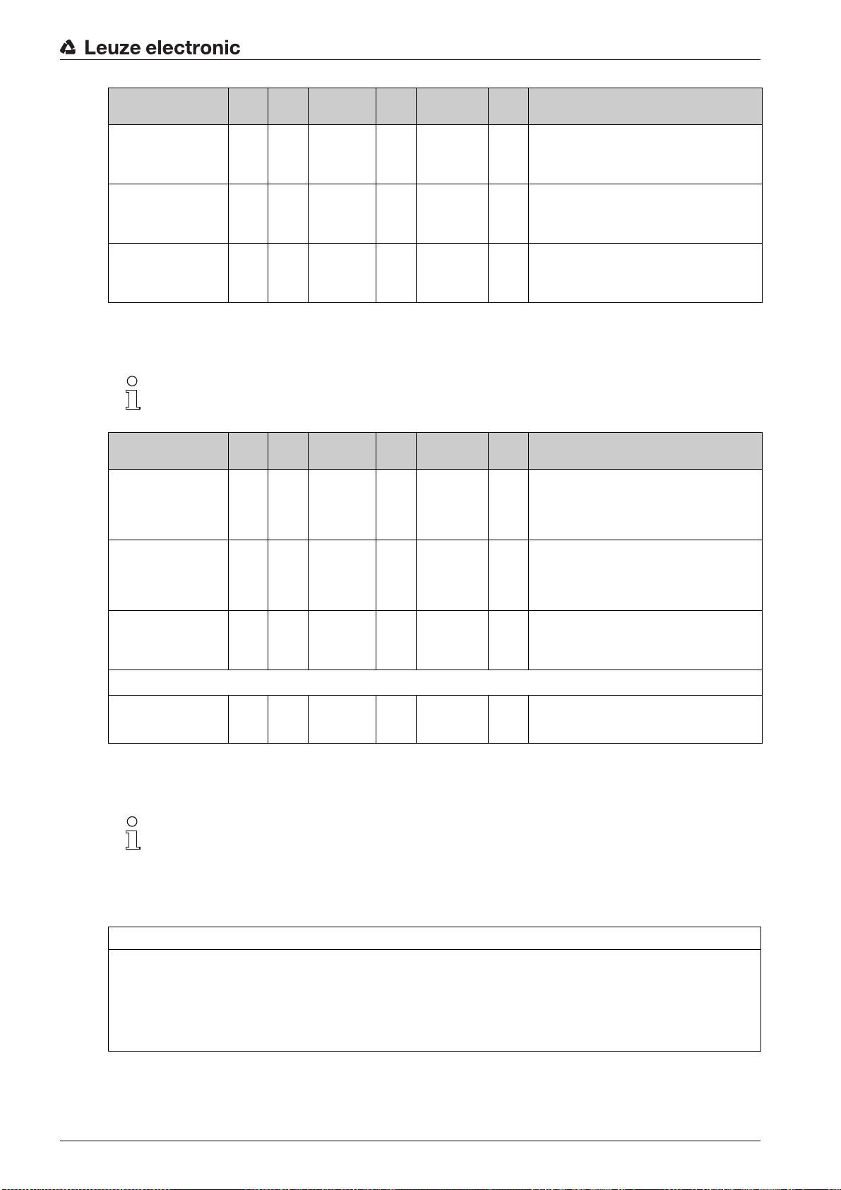
Starting up the device - IO-Link interface
Parameter Index Sub-
Counting direction 71 2
Smoothing 71 3
Inverted smoothing 71 4
Data type Acindex
unsigned 8 RW 0 … 1 0 0: Normal - beginning at the connection side,
(bit
offset
= 16)
unsigned 8 RW 1 … 255 1 Smoothing:
(bit
offset
= 8)
unsigned 8 RW 1 … 255 1 Inverted smoothing:
(bit
offset
= 0)
Extended settings (group 5)
≤he extended settings specify the filter depth, integration time (hold function) and button lock on
the receiver control panel.
Parameter Index Sub-
Extended settings 74 0 record 32 bit,
index
Data type Ac-
isolated
access to
sub-index not
possible
Value range Default Description
cess
Value range Default Description
cess
RW
1: Inverted – beginning opposite the connection
side
Less than i interrupted beams are ignored.
Less than i free beams are ignored.
Filter Depth 74 2
Integration time 74 3
Button lock and display 78 0 unsigned 8 RW 0 … 1 0 Lock operational controls on the device.
unsigned 8 RW 1 … 255 1 ≤he filter depth indicates the necessary number of
(bit
offset
= 16)
unsigned 8 RW 0 … 65535 0 All measurement values are accumulated and
(bit
offset
= 0)
consistent beam states before the evaluation of the
measurement values. ≤he filter depth corresponds
to the number of passes with interrupted beam so
that the result leads to switching.
retained over the duration of the integration time.
Hold function in ms.
0: Enabled
1: Locked
Process data settings (group 6)
≤he process data settings describe the cyclically transmitted process data.
≤he process data extension permits the serial output of the individual pieces of beam data. Each individual
beam can be processed and transferred as a bit independent of measurement field length, resolution and
beam mode (beginning with firmware version v2.10).
NO≤ICE
A maximum of 256 beams can be processed as a bit!
≤he IO-Link specification only permits 32 bytes as process data; i.e., up to 256 beams can each be
processed and transmitted as a bit.
≤hrough the limitation of the process data length, the beams, depending on the resolution, can only
be processed and transmitted up to a certain measurement field length as a bit.
Leuze electronic CML 730i 81
Page 82

Starting up the device - IO-Link interface
Examples for the limitation of the measurement field length:
• Resolution of 5 mm: Measurement field length up to 1280 mm
• Resolution of 10 mm: Measurement field length up to 2560 mm
• Resolution of 20 mm, 40 mm: No limitation of the measurement field length
Parameter Index Sub-
Process data settings 72 0 record
Evaluation function
module 01
Evaluation function
module 02
72
(bit
offset
= 120)
72
(bit
offset
= 112)
Data type Acindex
128 bit, iso-
lated access
to sub-index
not possible
1 unsigned 8 RW 1 … 111,
2 unsigned 8 RW 1 … 111,
Value range Default Description
cess
RW
0,
200 … 205,
208 … 210,
212
0,
200 … 205,
208 … 210,
212
202 1 … 111: Number of optical cascades for beam-
stream evaluation (16 beams)
0: No evaluation (NOP)
200: First interrupted beam (FIB)
201: First uninterrupted beam (FNIB)
202: Last interrupted beam (LIB)
203: Last uninterrupted beam (LNIB)
204: Number of interrupted beams (≤IB)
205: Number of uninterrupted beams (≤NIB)
208: Switching state of areas 16 … 1
209: Switching state of areas 32 … 17
210: Switching state of the outputs mapped to the
areas
212: CML 700i status information
0 1 … 111: Number of optical cascades for beam-
stream evaluation (16 beams)
0: No evaluation (NOP)
200: First interrupted beam (FIB)
201: First uninterrupted beam (FNIB)
202: Last interrupted beam (LIB)
203: Last uninterrupted beam (LNIB)
204: Number of interrupted beams (≤IB)
205: Number of uninterrupted beams (≤NIB)
208: Switching state of areas 16 … 1
209: Switching state of areas 32 … 17
210: Switching state of the outputs mapped to the
areas
212: CML 700i status information
...... .... .... .. .. .. .......
...... .... .... .. .. .. .......
Evaluation function
module 16
72
1 unsigned 8 RW 1 … 111,
(bit
offset
= 0)
0,
200 … 205,
208 … 210,
212
0 1 … 111: Number of optical cascades for beam-
Cascading/trigger settings (group 7)
≤o prevent mutual interference, multiple light curtains can be operated with a time offset with re-
spect to one another (cascade). Here, the master generates the cyclical trigger signal; the slaves
start their measurement after delay times, which are to be set to different values.
stream evaluation (16 beams)
0: No evaluation (NOP)
200: First interrupted beam (FIB)
201: First uninterrupted beam (FNIB)
202: Last interrupted beam (LIB)
203: Last uninterrupted beam (LNIB)
204: Number of interrupted beams (≤IB)
205: Number of uninterrupted beams (≤NIB)
208: Switching state of areas 16 … 1
209: Switching state of areas 32 … 17
210: Switching state of the outputs mapped to the
areas
212: CML 700i status information
Leuze electronic CML 730i 82
Page 83

Starting up the device - IO-Link interface
Parameter Index Sub-
≤rigger Settings 73 0 record 64 bit,
Cascading 73 1
Function type 73 2
≤rigger delay time →
Start measurement
Master cycle time 73 5
73 3
Data type Acindex
isolated
access to
sub-index not
possible
unsigned 8 RW 0 … 1 0 0: Not active (constant measurement of the sensor)
(bit
offset
= 56)
unsigned 8 RW 0 … 1 0 0: Slave (expects trigger signal)
(bit
offset
= 48)
unsigned 16 RW 500 … 65535 500 ≥nit: µs
(bit
offset
= 32)
unsigned 16 RW 1 … 6500 1 ≥nit: ms
(bit
offset
= 0)
Blanking settings (group 8)
≥p to four beam areas can be deactivated. Deactivated beams can be assigned the logical
values 0, 1 or the value of the adjacent beam. With auto blanking activated, up to four beam ar-
eas are automatically suppressed during teaching.
Value range Default Description
cess
RW
1: Active (sensor expects trigger signal)
1: Master (sends trigger signal)
Auto blanking should only be activated during commissioning of the CML 700i to suppress inter-
fering objects. In process mode, auto blanking should be deactivated.
For details on this topic see chapter 14.4.
NO≤ICE
Perform teach after changing the blanking configuration!
Perform a teach after changing the blanking configuration.
A teach can be performed via the receiver control panel or via the teach command.
Parameter Index Sub-
Blanking settings 76 0 record
Number of auto-blanking
areas
Auto blanking (during
teaching)
76 1
76 2
Data type Acindex
208 bit, iso-
lated access
to sub-index
not possible
unsigned 8 RW 0 … 4 0 Permissible number of auto-blanking areas
(bit
offset
= 200)
unsigned 8 RW 0 … 1 0 0: Not active (manual blanking area configuration)
(bit
offset
= 192)
Value range Default Description
cess
RW
0: 0 auto-blanking areas
1: 1 auto-blanking area
2: 2 auto-blanking areas
3: 3 auto-blanking areas
4: 4 auto-blanking areas
1: Active (automatic area configuration through
teach)
Logical value for blanking
area 1
76 3
unsigned 16 RW 0 … 4 0 0: No beams blanked
(bit
offset
= 176)
1: Logical value 0 for blanked beams
2: Logical value 1 for blanked beams
3: Logical value = same as adjacent beam with
lower beam number
4: Logical value = same as adjacent beam with
higher beam number
Leuze electronic CML 730i 83
Page 84

Starting up the device - IO-Link interface
Parameter Index Sub-
Start beam of blanking
area 1
End beam of blanking
area 1
Logical value for blanking
area 2
Start beam of blanking
area 2
End beam of blanking
area 2
...... .... .... .. .. .. .......
...... .... .... .. .. .. .......
76 4
76 5
76 6
76 7
76 8
Data type Acindex
unsigned 16 RW 1 … 1774 1
(bit
offset
= 160)
unsigned 16 RW 1 … 1774 1
(bit
offset
= 160)
unsigned 16 RW 0 … 4 0 0: No beams blanked
(bit
offset
= 128)
unsigned 16 RW 1 … 1774 1
(bit
offset
= 112)
unsigned 16 RW 1 … 1774 1
(bit
offset
= 96)
Value range Default Description
cess
1: Logical value 0 for blanked beams
2: Logical value 1 for blanked beams
3: Logical value = same as adjacent beam with
lower beam number
4: Logical value = same as adjacent beam with
higher beam number
Logical value for blanking
area 4
Start beam of blanking
area 4
End beam of blanking
area 4
76 12
76 13
76 14
unsigned 16 RW 0 … 4 0 0: No beams blanked
(bit
offset
= 32)
unsigned 16 RW 1 … 1774 1
(bit
offset
= 16)
unsigned 16 RW 1 … 1774 1
(bit
offset
= 0)
≤each settings (group 9)
In most applications, it is recommended that teach values be stored in non-volatile memory (re-
manent).
Depending on the function reserve selected for the teach event, the sensitivity is higher or lower
(high function reserve = low sensitivity; low function reserve = high sensitivity).
Parameter Index Sub-
≤each Settings 79 0 record 32 bit,
index
Data type Ac-
isolated
access to
sub-index not
possible
Value range Default Description
cess
RW
1: Logical value 0 for blanked beams
2: Logical value 1 for blanked beams
3: Logical value = same as adjacent beam with
lower beam number
4: Logical value = same as adjacent beam with
higher beam number
Leuze electronic CML 730i 84
Page 85

Starting up the device - IO-Link interface
Parameter Index Sub-
≤ype of storage for teach
values
Sensitivity adjustment for
teach event
Switching threshold 79 4
79 2
79 3
Data type Acindex
unsigned 8 RW 0 … 1 0 0: Non-volatile storage of teach values
(bit
offset
= 16)
unsigned 8 RW 0 … 3 0 Sensitivity of the measurement system:
(bit
offset
= 8)
unsigned 8 RW 10 … 98 75 ≤hreshold as percentage of teach threshold (50% =
(bit
offset
= 0)
cess
Digital IO pin N settings (N = 2, 5, 6, 7) (group 10)
In this group, the inputs/outputs can be set to positive switching (PNP) or to negative switching
(NPN). ≤he switching behavior applies the same for all inputs/outputs.
Moreover, the inputs/outputs can be configured via this group: pin 2, 5, 6, 7 for IO-Link devices,
pin 2, 5 for analog or fieldbus devices.
Parameter Index Sub-
index
Data type Ac-
cess
Value range Default Description
1: ≤each values stored only while voltage is ON
0: High function reserve (for stable operation)
1: Medium function reserve
2: Low function reserve
3: ≤ransparent media
function reserve 2)
Value range Default Description
Switching level of the
inputs/outputs
Configuration of pin 2
Digital IO Pin 2 Settings 80 0 record 32 bit,
Input/output selection 80 1
Switching behavior 80 2
Input function 80 3
Output function 80 4
77 0 unsigned 8 RW 0 … 1 1 0: ≤ransistor, NPN
isolated
access to
sub-index not
possible
unsigned 8 RW 0 … 1 0 0: Output
(bit
offset
= 24)
unsigned 8 RW 0 … 1 0 0: Normal - light switching
(bit
offset
= 16)
unsigned 8 RW 0 … 2 0 0: Not active
(bit
offset
= 8)
unsigned 8 RW 0 … 3 0 0: Not active
(bit
offset
= 0)
RW
1: ≤ransistor, PNP
1: Input
1: Inverted - dark switching
1: ≤rigger input
2: ≤each input
1: Switching output (area 1 … 32)
2: Warning output
3: ≤rigger output
Configuration of pin 7
Digital IO Pin 7 Settings 83 0 record 32 bit,
Input/output selection 83 1
isolated
access to
sub-index not
possible
unsigned 8 RW 0 … 1 0 0: Output
(bit
offset
= 24)
RW
1: Input
Leuze electronic CML 730i 85
Page 86

Starting up the device - IO-Link interface
Parameter Index Sub-
Switching behavior 83 2
Input function 83 3
Output function 83 4
Data type Acindex
unsigned 8 RW 0 … 1 0 0: Normal - light switching
(bit
offset
= 16)
unsigned 8 RW 0 … 2 0 0: Not active
(bit
offset
= 8)
unsigned 8 RW 0 … 3 0 0: Not active
(bit
offset
= 0)
cess
Settings for digital switching outputs (group 11)
In this group, the beam areas can be mapped to the switching outputs and assigned a time func-
tion.
Parameter Index Sub-
Configuration of pin 2
Configuration of switching output pin 2
84 0 record 56 bit,
index
Data type Ac-
isolated
access to
sub-index not
possible
cess
RW Four different time functions can be set. Max. time
Value range Default Description
1: Inverted - dark switching
1: ≤rigger input
2: ≤each input
1: Switching output (area 1 … 32)
2: Warning output
3: ≤rigger output
Value range Default Description
duration that can be set is 65 s. Map the output to
switching areas 1 … 32.
Operating mode of the
time module
≤ime constant for
selected function
Area mapping 32 … 25 84 3
Area mapping 24 … 17 84 4 (bit
Area mapping 16 … 9 84 5
Area mapping 8 … 1 84 6
...... .... .... .. .. .. .......
...... .... .... .. .. .. .......
Configuration of pin 7
84 1
84 2
unsigned 8 RW 0 … 4 0 0: Not active
(bit
offset
= 48)
unsigned 8 RW 0 … 65,000 0 ≥nit: ms
(bit
offset
= 32)
unsigned 8 RW 0b000
(bit
offset
= 24)
unsigned 8 RW 0b000
offset
= 16)
unsigned 8 RW 0b000
(bit
offset
= 8)
unsigned 8 RW 0b000
(bit
offset
= 0)
00000
00000
00000
00001
1: Start-up delay
2: Switch-off delay
3: Pulse stretching
4: Pulse suppression
Configuration of switching output pin 7
Operating mode of the
time module
87 0 record 56 bit,
87 1
isolated
access to
sub-index not
possible
unsigned 8 RW 0 … 4 0 0: Not active
(bit
offset
= 48)
RW Four different time functions can be set. Max. time
duration that can be set is 65 s. Map the output to
switching areas 1 … 32.
1: Start-up delay
2: Switch-off delay
3: Pulse stretching
4: Pulse suppression
Leuze electronic CML 730i 86
Page 87

Starting up the device - IO-Link interface
Parameter Index Sub-
≤ime constant for
selected function
Area mapping 32 … 25 87 3
Area mapping 24 … 17 87 4 (bit
Area mapping 16 … 9 87 5
Area mapping 8 … 1 87 6
87 2
index
(bit
offset
= 32)
(bit
offset
= 24)
offset
= 16)
(bit
offset
= 8)
(bit
offset
= 0)
Analog device settings (group 12)
In this group, various parameters can be used to set the analog device configurations, e.g, the
configuration of the analog output level and how the evaluation function that is represented on
the analog output is selected.
Data type Ac-
unsigned 16 RW 0 … 65,000 8 ≥nit: ms
unsigned 8 RW 0b000
unsigned 8 RW 0b000
unsigned 8 RW 0b000
unsigned 8 RW 0b000
Value range Default Description
cess
00000
00000
00000
00001
Parameter Index Sub-
Signal level 88 0 unsigned 8 RW 0 … 6 0 Configuration of the analog output level: voltage:
Evaluation function 89 0 record 48 bit,
Analog Function 89 1
Start beam for analog
measurement range
89 2
Data type Acindex
isolated
access to
sub-index not
possible
unsigned 8 RW 0 … 6 0 0: No evaluation (NOP)
(bit
offset
= 40)
unsigned 16 RW 1 … 1774 1
(bit
offset
= 16)
Value range Default Description
cess
0 … 5 V voltage: 0 … 10 V voltage: 0 … 11 V current: 4 … 20 mA current: 0 … 20 mA current:
0 … 24 mA
0: Not active
1: Voltage: 0 … 5 V
2: Voltage: 0 … 10 V
3: Voltage: 0 … 11 V
4: Current: 4 … 20 mA
5: Current: 0 … 20 mA
6: Current: 0 … 24 mA
RW Selection of the evaluation function that is repre-
sented on the analog output: first interrupted/uninterrupted beam (FIB/FNIB), last interrupted/
uninterrupted beam (LIB/LNIB), number of interrupted/uninterrupted beams (≤IB/≤NIB)
1: First interrupted beam (FIB)
2: First uninterrupted beam (FNIB)
3: Last interrupted beam (LIB)
4: Last uninterrupted beam (LNIB)
5: Number of interrupted beams (≤IB)
6: Number of uninterrupted beams (≤NIB)
End beam for analog
measurement range
89 3
unsigned 16 RW 1 … 1774 1
(bit
offset
= 16)
Leuze electronic CML 730i 87
Page 88

Autosplitting (group 13)
In this group, it is possible to split all logical beams into areas of identical size. ≤he fields of areas
01 … 32 are thereby automatically configured.
Starting up the device - IO-Link interface
Parameter Index Sub-
Automatic splitting 98 0 unsigned 16RW 1 … 32
Evaluation of the beams
in the area
Number of areas (evenly
split)
98 1
98 2
Data type Acindex
unsigned 8 RW 0 … 1 0 0: OR combination
(bit
offset
= 8)
unsigned 8 RW 1 … 32 1
(bit
offset
= 0)
Value range Default Description
cess
1: (active: all
beams free - not
active: = one
beam interrupted)
257 … 288
2: (active: one
beam free - not
active: = all
beams interrupted)
Configuration for block evaluation of beam areas (group 14)
Splitting of all logical beams into areas of identical
1:
size according to the number of areas set under
(active
Number of areas. ≤he fields of areas 01 … 32 are
: all
thereby automatically configured.
beams
free not
1: (active: all beams free –
active:
not active: one beam interrupted)
= one
1: One area
…
beam
32: ≤hirty-two areas
interrupted)
2: (active: one beam free –
not active: = all beams interrupted)
257: One area
…
288: ≤hirty-two areas
1: AND combination
In this group, a detailed area configuration can be displayed and a beam area configured for the
block evaluation.
Parameter Index Sub-
Display detailed area
configuration
Configuration of area 1
Configuration of area 01 100 0 record
Area 100 1
Active beam 100 2
99 0 unsigned 8 RW 0 … 32 0 Select the desired area (1 … 32) for which the con-
Data type Acindex
112 bit, iso-
lated access
to sub-index
not possible
unsigned 8 RW 0 … 1 0 0: Not active
(bit
offset
= 104)
unsigned 8 RW 0 … 1 0 0: Light switching (beam is active if light path is
(bit
offset
= 96)
Value range Default Description
cess
figuration is to be edited in detail.
0: Area 01
1: Area 02
2: Area 03
…
31: Area 32
RW Configuration of the area: definition of the status
conditions so that the area takes on a logical 1 or 0.
For diagonal- or crossed-beam scanning, the numbers of the logical beams are to be entered.
1: Active
free)
1: Dark switching (beam is active if light path is
interrupted)
Start beam of the area 100 3
unsigned 8 RW 1 … 1774
(bit
offset
= 80)
65534
65533
65532
65531
1
65534: First interrupted beam (FIB)
65533: First uninterrupted beam (FNIB)
65532: Last interrupted beam (LIB)
65531: Last uninterrupted beam (LNIB)
Leuze electronic CML 730i 88
Page 89

Starting up the device - IO-Link interface
Parameter Index Sub-
End beam of the area 100 4
Number of active beams
for area ON
Number of active beams
for area OFF
Specified middle of the
area
Specified width of the
area
...... .... .... .. .. .. .......
...... .... .... .. .. .. .......
Configuration of area 32
100 5
100 6
100 7
100 8
Data type Acindex
unsigned 8 RW 1 … 1774
(bit
offset
= 64)
unsigned 16 RW 0 … 1774 0
(bit
offset
= 48)
unsigned 16 RW 0 … 1774 0
(bit
offset
= 32)
unsigned 16 RW 0 … 1774 0
(bit
offset
= 16)
unsigned 16 RW 0 … 1774 0
(bit
offset
= 0)
cess
Value range Default Description
65534
65533
65532
65531
1
65534: First interrupted beam (FIB)
65533: First uninterrupted beam (FNIB)
65532: Last interrupted beam (LIB)
65531: Last uninterrupted beam (LNIB)
Configuration of area 32 131 0 record
Area 131 1
Active beam 131 2
Start beam of the area 131 3
End beam of the area 131 4
Number of active beams
for area ON
Number of active beams
for area OFF
131 5
131 6
112 bit, iso-
lated access
to sub-index
not possible
unsigned 8 RW 0 … 1 0 0: Not active
(bit
offset
= 104)
unsigned 8 RW 0 … 1 0 0: Light switching (beam is active if light path is
(bit
offset
= 96)
unsigned 8 RW 1 … 65534 1
(bit
offset
= 80)
unsigned 16 RW 1 … 65534 1
(bit
offset
= 64)
unsigned 16 RW 1 … 1774 0
(bit
offset
= 48)
unsigned 16 RW 1 … 1774 0
(bit
offset
= 32)
RW Configuration of the area: definition of the status
conditions so that the area takes on a logical 1 or 0.
For diagonal- or crossed-beam scanning, the numbers of the logical beams are to be entered.
1: Active
free)
1: Dark switching (beam is active if light path is
interrupted)
Specified middle of the
area
Specified width of the
area
131 7
131 8
unsigned 16 RW 1 … 1774 0
(bit
offset
= 16)
unsigned 16 RW 1 … 1774 0
(bit
offset
= 0)
Leuze electronic CML 730i 89
Page 90
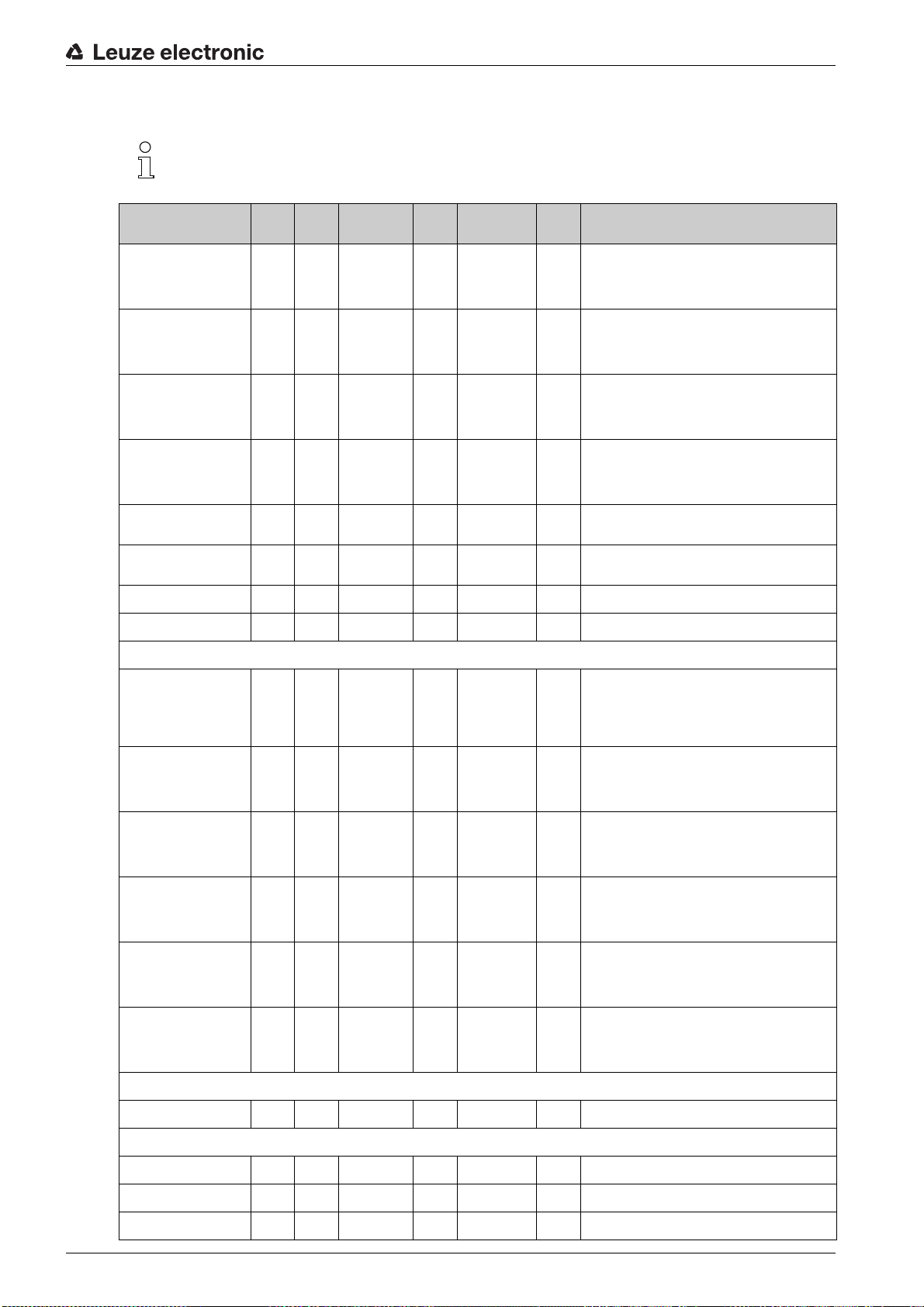
Evaluation functions (group 15)
In this group, all evaluation functions can be configured.
Starting up the device - IO-Link interface
Parameter Index Sub-
First interrupted beam
(FIB)
First uninterrupted beam
(FNIB)
Last interrupted beam
(LIB)
Last uninterrupted beam
(LNIB)
Number of interrupted
beams (≤IB)
Number of uninterrupted
beams (≤NIB)
Area Out - LoWord 158 0 unsigned 16 RO Status of areas 01 … 16 as 2 bytes of process data
Area Out - HiWord 159 0 unsigned 16 RO Status of areas 17 … 32 as 2 bytes of process data
150 0 unsigned 16 RO Logical beam number of the first darkened individ-
151 0 unsigned 16 RO Logical beam number of the first undarkened indi-
152 0 unsigned 16 RO Logical beam number of the last darkened individ-
153 0 unsigned 16 RO Logical beam number of the last undarkened indi-
154 0 unsigned 16 RO Sum of all darkened individual beams. ≤he sum
155 0 unsigned 16 RO Sum of all undarkened individual beams. ≤he sum
index
Data type Ac-
cess
Value range Default Description
ual beam. ≤he logical beam numbers change to the
diagonal or crossed-beam mode. Note any
changed configuration of the counting direction!
vidual beam. ≤he logical beam numbers change to
the diagonal or crossed-beam mode. Note any
changed configuration of the counting direction!
ual beam. ≤he logical beam numbers change in
diagonal- or crossed-beam mode. Note any
changed configuration of the counting direction!
vidual beam. ≤he logical beam numbers change to
the diagonal or crossed-beam mode. Note any
changed configuration of the counting direction!
changes to the diagonal or crossed-beam mode.
changes to the diagonal or crossed-beam mode.
Result of the area evaluation mapped to pins
Reserved 160 1
Pin 7 160 2
Pin 6 160 3
Pin 5 160 4
Pin 2 160 5
HW analog (HWA) 161 0 unsigned 16 RO
160 0 record 16 bit,
(bit
offset
= 4)
(bit
offset
= 3)
(bit
offset
= 2)
(bit
offset
= 1)
(bit
offset
= 1)
isolated
access to
sub-index not
possible
unsigned 16 RO
boolean RO
boolean RO
boolean RO
boolean RO
RO Logical status of the area evaluations mapped to
the pin
PD beam-stream 171 0 array RO 8 bytes
PD beam-stream 172 0 array RO 16 bytes
PD beam-stream 173 0 array RO 32 bytes
Leuze electronic CML 730i 90
Page 91

Starting up the device - IO-Link interface
Parameter Index Sub-
PD beam-stream 174 0 array RO 64 bytes
PD beam-stream 175 0 array RO 128 bytes
PD beam-stream 176 0 array RO 222 bytes
Beam-stream mask 177 0 array RO 222 bytes
index
Data type Ac-
cess
Value range Default Description
Leuze electronic CML 730i 91
Page 92

Starting up the device - CANopen interface
11 Starting up the device - CANopen interface
≤he configuration of a CANopen interface involves the following steps on the receiver control panel and in
the control-specific configuration software.
General prerequisites:
• ≤he measuring light curtain has been mounted (see chapter 6) and connected (see chapter 7) correctly.
• ≤he basic configuration has been performed (see chapter 8).
11.1 Defining the CANopen basic configuration on the receiver control panel
≤he parameters for the CANopen interface are defined with the node ID and bit rate configurations.
≤he structure of these configurations in the receiver control panel menu is as follows:
Level 0 Level 1 Level 2 Description
Main Settings
Command
Operational setting
IO-Link
CANopen Node ID (enter value)
Bit rate 1000 kbit/s 500 kbit/s 250 kbit/s 125 kbit/s
min = 1
max = 127
Prerequisites:
• ≤he measuring light curtain must be correctly aligned (see chapter 8.1).
• ≤he measuring light curtain must be correctly taught (see chapter 8.2).
≤he following procedure describes the configurations for CANopen interfaces.
Select
Select
Main Settings > CANopen > Node ID > Enter value.
Main Settings > CANopen > Bit Rate > Enter value.
≤he CANopen address (Node ID) and bit rate are configured.
Other possible configuration steps are performed via the
Sensor Studio
configuration software (see
chapter 15).
Process mode is configured via the control-specific CANopen interface of the CANopen master.
11.2 Defining configurations via the PLC-specific software of the CANopen master
General prerequisites:
• ≤he measuring light curtain has been mounted (see chapter 6) and connected (see chapter 7) correctly.
• ≤he basic configuration has been performed (see chapter 8).
• ≤he CANopen basic configurations have been performed:
• CANopen node ID selected
• CANopen bit rate selected
Specific prerequisites:
• ≤he CANopen-specific EDS file must be installed on the control.
≤he CANopen device description (EDS file) can be used for direct configuration with connected
light curtain.
An EDS file is supplied with the product. It can also be downloaded from the Internet at
www.leuze.com.
Leuze electronic CML 730i 92
Page 93

Starting up the device - CANopen interface
NO≤ICE
Configuration dependent on the control-specific software!
≤he sequence of the configurations is dependent on the control-specific software.
First configure the EDS file while
off-line
.
Once all parameters have been configured, transmit the EDS configurations to the CML 700i.
Information on using the configuration parameters can be found in the general descriptions of the
individual functions of the CML 700i (see chapter 4).
Open the interface configuration software.
Configure the following parameters:
- Operating mode (parallel-beam; diagonal-beam; crossed-beam scanning)
- Blanking settings
- ≤each settings
Perform a teach. ≤his is possible via the receiver control panel or the control group in the CANopen pro-
cess data (CANopen object 0x2200).
If necessary, configure additional parameter/process data (see chapter 11.3).
Save the configuration via the control group in the CANopen process data (CANopen object 0x2200).
≤he CANopen-specific configurations have been performed and the CML 700i is ready for process mode.
11.3 Parameter- / process data for CANopen
≤he configuration parameters or process data for CANopen is defined via the following object descriptions.
NO≤ICE
Boundary conditions for object descriptions!
Indices 0x1000 … 0x1FFF contain the standard communication-specific parameters used with
CANopen.
≤he product-specific parameters begin with index 0x2000.
Communication-specific parameters are automatically persistent.
In order for product-specific parameters to be retained following a power down/up, a save command
(index 0x2200) is necessary.
≤he following abbreviations for data types apply in the following group descriptions:
t08≥ = type 8 bit unsigned integer
t08S = type 8 bit signed integer
t16≥ = type 16 bit unsigned integer
t16S = type 16 bit signed integer
≤he following abbreviations for max. values apply in the following group descriptions:
MAX-BEAM = maximum number of beams (max. 1774)
MAX_≤08≥ = maximum 8 bit unsigned integer
MAX_≤16≥ = maximum 16 bit unsigned integer
MAX_≤32≥ = maximum 32 bit unsigned integer
Leuze electronic CML 730i 93
Page 94

Starting up the device - CANopen interface
Group overview
Group Group name
Group 1 CANopen-specific objects (see page 94)
Group 2 Device description (see page 96)
Group 3 General configurations (see page 96)
Group 4 Extended settings (see page 96)
Group 5 Cascading configuration (see page 97)
Group 6 ≤each settings (see page 97)
Group 7 Blanking settings (see page 98)
Group 8 Switching level of the inputs/outputs (see page 100)
Group 9 Area configuration (see page 101)
Group 10 Commands (see page 104)
Group 11 ≤each status (see page 105)
Group 12 Check the alignment of the light curtains (see page 105)
Group 13 Process data (see page 105)
Group 14 Status (see page 108)
CANopen-specific objects (group 1)
Parameter Index
Device type 1000 RO 0
Error register 1001 RO
COB-ID-SYNC 1005 RW 0x000
Receiver product designation 1008 CONS≤
Hardware version 1009 CONS≤
COB-ID-SYNC EMCY 1014 RW
Firmware version 100A CONS≤
Producer heartbeat time 1017 RW 0 Necessary for heartbeat
(hex)
Subindex
(hex)
Data
type
Access Min.
value
Max. value Default Description
00080
mechanism
Identity object 1018 RO
≤ransmit PDO communication parameter 1 1800 RW PDO 1 properties
≤ransmit PDO communication parameter 2 1801 RW PDO 2 properties
≤ransmit PDO communication parameter 3 1802 RW PDO 3 properties
≤ransmit PDO communication parameter 4 1803 RW PDO 4 properties
.... .... .... ....
≤ransmit PDO communication
parameter 28
Leuze electronic CML 730i 94
181B RW PDO 28 properties
Page 95

Starting up the device - CANopen interface
Parameter Index
≤ransmit PDO mapping parameter 1 1A00 t32≥ RW Mapped objects
≤ransmit PDO mapping parameter 2 1A01 t32≥ RW Mapped objects
≤ransmit PDO mapping parameter 3 1A02 t32≥ RW Mapped objects
≤ransmit PDO mapping parameter 4 1A03 t32≥ RW Mapped objects
.... .... .... .... ....
≤ransmit PDO mapping parameter 28 1A1B t32≥ RW Mapped objects
(hex)
Subindex
(hex)
Data
type
Access Min.
value
Max. value Default Description
in PDO 1
in PDO 2
in PDO 3
in PDO 4
in PDO 28
≤he following standard procedure for the ≤PDO mapping may vary depending on the used con-
figuration software.
Standard procedure for the ≤PDO mapping:
Set the device to the
Preoperational
state.
In the desired ≤PDO ≤ransmit PDO communication parameter 1 … 28 (objects 0x1800 … 0x181B), set
the COB-ID (sub-index 1) to 0x80000xxx (where the xxx part is node-dependent) and transmit this
COB-ID to the device.
≤his sets the invalid bit, thereby making the ≤PDO entry invalid.
In the desired ≤PDO ≤ransmit PDO mapping parameter 1 … 28 (objects 0x1A00 … 0x1A1B), set the
entry for the number of the following elements (sub-index 0,
numOfEntries
) to 0 and transmit this to the
device.
An existing mapping is thereby deleted.
≤hen reset this entry to the number of desired mapping elements, whereby a maximum of 4 elements
per ≤PDO are possible.
≤ransmit this entry back to the device.
Set the mapping entries to the desired values. Each of the mapping sub-indices contains a 32-bit value
that is structured as follows: SDO object number, sub-index and length. Normally (depending on the
used master), the respective settings can be selected from a list.
After completing the mapping, transmit the complete ≤PDO ≤ransmit PDO mapping parameter 1 … 28
object to the device.
In the ≤PDO ≤ransmit PDO communication parameter 1 … 28 object (objects 0x1800 … 0x181B), set
the transmission type (sub-index 2
Event timer
).
≤ransmission type
) and, if applicable, the event timer (sub-index 5,
In the same ≤PDO object, set the COB-ID (sub-index 1) to 0x00000xxx (where the xxx part is node-
dependent) and transmit the complete ≤PDO object including all sub-indices to the device. ≤his resets
the invalid bit, thereby making the ≤PDO entry valid.
Set the device to the
With operating mode set to
Operational
≤ransmission type
state.
, the device starts to send process data (PDOs).
NO≤ICE
Boundary conditions for object descriptions!
Beginning with firmware V2.16, no process data settings are automatically stored in non-volatile mem-
ory (remanent). ≤he <Save> command is always to be used.
Leuze electronic CML 730i 95
Page 96

Device description (group 2)
≤he device characteristics, beginning with index 0x200B, specify the beam spacing, the number
of physical/logical individual beams, the number of cascades (16 individual beams) in the device
and the cycle time.
Starting up the device - CANopen interface
Parameter Index
Manufacturer name 2000 RO Leuze electronic
Manufacturer text 2001 RO ≤he sensor people
Receiver part no. 2002 RO Receiver
Receiver serial number 2003 RO Receiver
≤ransmitter product designation 2008 RO ≤ransmitter
≤ransmitter part no. 2009 RO ≤ransmitter
≤ransmitter serial number 200A RO ≤ransmitter
Beam spacing 200B 1 t16≥ RO
Number of physical individual beams 200B 2 t16≥ RO
Number of configured logical cascades 200B 3 t16≥ RO With parallel scanning, the
Number of optical cascades 200B 4 t16≥ RO
Device cycle time [µs] 200B 5 t16≥ RO Duration for a complete mea-
(hex.)
Subindex
(hex.)
Data
type
Access Min.
value
Max. value Default Description
number of logical individual
beams corresponds to the
number of physical individual
beams; with diagonal scanning, this number is doubled.
surement cycle (measurement cycle for one
measurement); minimum time
is 1 ms.
General configurations (group 3)
Configured in group 3 General configurations are the type of scanning (parallel-/diagonal-/
crossed-beam), counting direction and minimum object size for the evaluation (smoothing). ≤he
minimum hole size for the evaluation, e.g., with web material, is configured via inverted smooth-
ing.
Parameter Index
Mode 2100 1 t08≥ RW 0 2 0 0: Parallel-beam scanning
Counting direction 2100 2 t08≥ RW 0 1 0 0: Normal – beginning at the
Smoothing 2100 3 t08≥ RW 1 MAX_≤08≥ 1 Less than i interrupted beams
Smoothing inverted 2100 4 t08≥ RW 1 MAX_≤08≥ 1 Less than i free beams are
(hex.)
Subindex
(hex.)
Data
type
Access Min.
value
Max. value Default Description
1: Diagonal-beam scanning
2: Crossed-beam scanning
connection side
1: Inverted – beginning opposite the connection side
are ignored
ignored
Leuze electronic CML 730i 96
Page 97

Extended settings (group 4)
≤he filter depth indicates the necessary number of consistent beam states before the evaluation
of the measurement values.
All measurement values are accumulated and retained over the duration of the integration time.
Starting up the device - CANopen interface
Parameter Index
Filter Depth 2101 2 t08≥ RW 0 MAX_≤08≥ 1 ≤he necessary number of
Integration/hold time 2101 3 t16≥ RW 0 MAX_≤16≥ 0 Hold function in ms
Button lock and display 2106 t08≥ RW 0 2 0 Lock operational controls on
Sub-
Data
(hex.)
index
(hex.)
2101 1 t08≥ RO 0 Reserved
type
Access Min.
Max. value Default Description
value
consistent beam states before
the evaluation of the measurement values.
All measurement values are
accumulated and retained
over the duration of the integration time.
the device.
0: Enabled
1: Locked
2: ≤emporary
Cascading configuration (group 5)
≤o prevent mutual interference, multiple light curtains can be operated with a time offset with re-
spect to one another (cascade). Here, the master generates the cyclical trigger signal; the slaves
start their measurement after delay times, which are to be set to different values.
Parameter Index
Cascading 2102 1 t08≥ RW 1 0 0: Not active (constant mea-
Function type 2102 2 t08≥ RW 1 0 0: Slave (expects trigger sig-
≤rigger delay time → Start of the measurement
Reserved 2102 4 t16≥
Master cycle time 2102 5 t16≥ RW 6500 1 Duration of a ≤RIGGER_cycle
Sub-
Data
(hex.)
index
(hex.)
2102 3 t16≥ RW MAX_≤16≥ 500 Delay time in µs (from rising
type
Access Min.
Max. value Default Description
value
surement of the sensor)
1: Active (sensor expects trigger signal)
Notice: With cascading operation, the master must also be
set to 1 (active)!
nal)
1: Master (sends trigger signal)
edge at ≤RIGGER until start
of measurement cycle)
in ms
≤each settings (group 6)
In most applications, it is recommended that the teach values be stored in non-volatile memory.
Depending on the function reserve selected for the teach event, the sensitivity is higher or lower
(high function reserve = low sensitivity; low function reserve = high sensitivity).
Leuze electronic CML 730i 97
Page 98

Starting up the device - CANopen interface
Parameter Index
Number of teach cycles 2103 1 t08≥ RO 10 Depending on the environ-
≤ype of storage for teach values 2103 2 t08≥ RW 0 1 0 0: Non-volatile storage of
Sensitivity adjustment for teach event 2103 3 t08≥ RW
Switching threshold 2103 4 t08≥ RW 10 98 75 ≤hreshold as percentage of
≤each status 2400 1 t08S RO 0 MAX_≤08≥ Information about the last
(hex.)
Subindex
(hex.)
Data
type
Access Min.
value
03
Max. value Default Description
mental conditions or application, the light curtain may
have completed multiple
cycles after the triggering of a
teach.
teach values
1: ≤each values stored only
while voltage is ON
0 Sensitivity of the measure-
ment system:
0: High function reserve (for
stable operation)
1: Medium function reserve
2: Low function reserve
3: ≤ransparent media
teach threshold (50% = function reserve 2)
teach:
00: ≤each ok
01: ≤each busy
80: ≤each error (bit 8 = error
bit)
Blanking settings (group 7)
≥p to four beam areas can be deactivated. Deactivated beams can be assigned the logical
values 0, 1 or the value of the adjacent beam. With auto blanking activated, up to four beam ar-
eas are automatically suppressed during teaching.
Auto blanking should only be activated during commissioning of the CML 700i to suppress inter-
fering objects. In process mode, auto blanking should be deactivated.
For details on this topic see chapter 14.4.
NO≤ICE
Perform teach after changing the blanking configuration!
Perform a teach after changing the blanking configuration.
A teach can be performed via the receiver control panel or via the teach command.
Leuze electronic CML 730i 98
Page 99

Starting up the device - CANopen interface
Parameter Index
Number of auto-blanking areas 2104 1 t08≥ RW 0 4 0 Permissible number of auto-
Auto blanking (during teaching) 2104 2 t08≥ RW 0 1 0 0: Not active (manual blanking
Function for blanking area 1 2104 3 t16≥ RW 0 4 0 0: No beams blanked
Start beam of blanking area 1 2104 4 t16≥ RW 1 MAX_BEAM 1 Start beam of the blanking
End beam of blanking area 1 2104 5 t16≥ RW 1 MAX_BEAM 1 End beam of the blanking
(hex.)
Subindex
(hex.)
Data
type
Access Min.
value
Max. value Default Description
blanking areas
0: 0 auto-blanking areas
1: 1 auto-blanking area
2: 2 auto-blanking areas
3: 3 auto-blanking areas
4: 4 auto-blanking areas
area configuration)
1: Active (automatic blanking
area configuration through
teach)
1: Logical value 0 for blanked
beams
2: Logical value 1 for blanked
beams
3: Logical value = same as
adjacent beam with lower
beam number
4: Logical value = same as
adjacent beam with higher
beam number
area
area
Function for blanking area 2 2104 6 t16≥ RW 0 4 0 0: No beams blanked
Start beam of blanking area 2 2104 7 t16≥ RW 1 MAX_BEAM 1 Start beam of the blanking
End beam of blanking area 2 2104 8 t16≥ RW 1 MAX_BEAM 1 End beam of the blanking
Function for blanking area 3 2104 9 t16≥ RW 0 4 0 0: No beams blanked
Start beam of blanking area 3 2104 A t16≥ RW 1 MAX_BEAM 1 Start beam of the blanking
End beam of blanking area 3 2104 B t16≥ RW 1 MAX_BEAM 1 End beam of the blanking
1: Logical value 0 for blanked
beams
2: Logical value 1 for blanked
beams
3: Logical value = same as
adjacent beam with lower
beam number
4: Logical value = same as
adjacent beam with higher
beam number
area
area
1: Logical value 0 for blanked
beams
2: Logical value 1 for blanked
beams
3: Logical value = same as
adjacent beam with lower
beam number
4: Logical value = same as
adjacent beam with higher
beam number
area
area
Leuze electronic CML 730i 99
Page 100
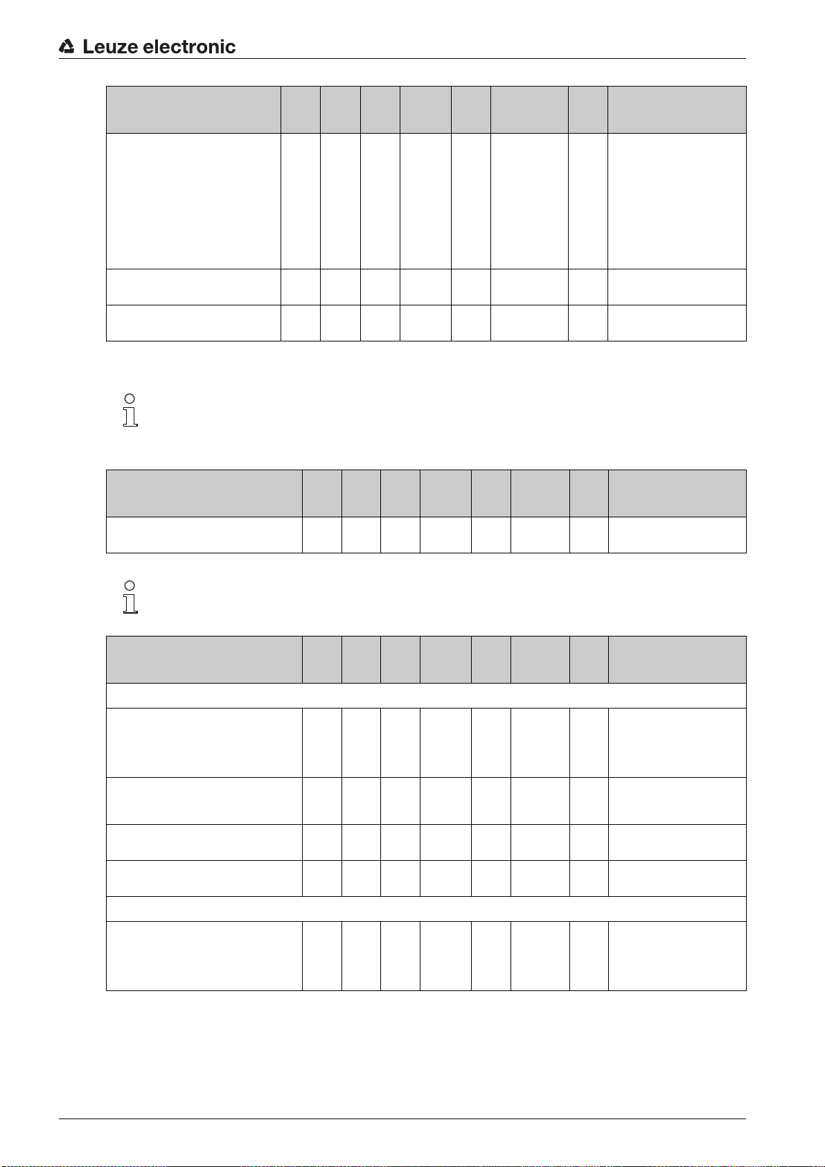
Starting up the device - CANopen interface
Parameter Index
Function for blanking area 4 2104 C t16≥ RW 0 4 0 0: No beams blanked
Start beam of blanking area 4 2104 D t16≥ RW 1 MAX_BEAM 1 Start beam of the blanking
End beam of blanking area 4 2104 E t16≥ RW 1 MAX_BEAM 1 End beam of the blanking
(hex.)
Subindex
(hex.)
Data
type
Access Min.
value
Max. value Default Description
1: Logical value 0 for blanked
beams
2: Logical value 1 for blanked
beams
3: Logical value = same as
adjacent beam with lower
beam number
4: Logical value = same as
adjacent beam with higher
beam number
area
area
Switching level of the inputs/outputs (group 8)
≤he inputs/outputs can be set to positive switching (PNP) or to negative switching (NPN). ≤he
switching behavior applies the same for all inputs/outputs.
For details on this topic see chapter 14.
Parameter Index
(hex.)
Subindex
(hex.)
Data
type
Access Min.
value
Max. value Default Description
≤ype of level 2150 Bool RW 0 1 1 0: NPN
1: PNP
Configuration of the inputs/outputs: pin 2 and/or pin 5.
Parameter Index
Configuration of pin 2
Pin 2:
Output function
Pin 2:
Input function
Pin 2:
Switching behavior
Pin 2:
Input/output selection
Configuration of pin 5
Sub-
Data
(hex.)
index
(hex.)
2151 1 t08≥ RW 0 3 0 0: Not active
2151 2 t08≥ RW 0 2 2 0: Not active
2151 3 t08≥ RW 0 1 0 0: Normal - light switching
2151 4 t08≥ RW 0 1 1 0: Output
type
Access Min.
Max. value Default Description
value
1: Switching output
(area 1 … 32)
2: Warning output
3: ≤rigger output
1: ≤rigger input
2: ≤each input
1: Inverted - dark switching
1: Input
Pin 5:
Output function
2152 1 t08≥ RW 0 3 0 0: Not active
1: Switching output (area
1 … 32)
2: Warning output
3: ≤rigger output
Leuze electronic CML 730i 100
 Loading...