

Page 1

BPS 37
Bar code positioning system - SSI interface
en 03-2018/11 50124376
We reserve the right to
make technical changes
Original operating instructions
Page 2

© 2018
Leuze electronic GmbH + Co. KG
In der Braike 1
73277 Owen / Germany
Phone: +49 7021 573-0
Fax: +49 7021 573-199
http://www.leuze.com
info@leuze.com
Leuze electronic BPS 37
Page 3

Table of contents
1 General information ........................................................................................................... 3
1.1 Explanation of symbols ........................................................................................................ 3
1.2 Declaration of Conformity ....................................................................................................3
2 Safety .................................................................................................................................. 4
2.1 Intended use ........................................................................................................................ 4
2.2 Foreseeable misuse.............................................................................................................5
2.3 Competent persons.............................................................................................................. 5
2.4 Exemption of liability ............................................................................................................ 6
2.5 Laser safety notices ............................................................................................................. 6
3 Description ......................................................................................................................... 8
3.1 Device construction of the BPS 37 ...................................................................................... 8
3.2 Application ........................................................................................................................... 8
3.3 Function ............................................................................................................................... 8
3.4 Advantages ..........................................................................................................................9
3.5 Stand-alone operation.......................................................................................................... 9
4 Technical data .................................................................................................................. 12
4.1 General specifications BPS 37 .......................................................................................... 12
4.2 LED indicators.................................................................................................................... 13
4.3 Dimensioned drawings....................................................................................................... 13
4.4 BPS 37 reading field curve ................................................................................................ 15
5 Accessories/order codes ................................................................................................ 16
5.1 Accessories........................................................................................................................16
5.1.1 Connection units / connector hood..............................................................................................16
5.1.2 Mounting accessories.................................................................................................................. 18
5.1.3 Interconnection cable...................................................................................................................18
6 Installation ........................................................................................................................ 19
6.1 Storage, transportation ......................................................................................................19
6.2 Mount .................................................................................................................................19
6.2.1 Device arrangement ....................................................................................................................21
6.3 Connect.............................................................................................................................. 24
6.3.1 Connecting the BPS 37 (SSI) ......................................................................................................24
6.3.2 Connecting the SSI interface.......................................................................................................25
6.3.3 Connecting the switching input and switching output ..................................................................27
6.3.4 Connection with MS 37 103 modular connector hood.................................................................28
6.3.5 Cable lengths and shielding......................................................................................................... 31
6.4 Disassembling, packing, disposing .................................................................................... 31
Leuze electronic BPS 37 1
Page 4

Table of contents
7 Commissioning ................................................................................................................ 32
7.1 Measures to be performed prior to the initial commissioning............................................. 32
7.2 Function Test ..................................................................................................................... 32
7.3 Setting the parameters.......................................................................................................32
7.3.1 Parameter sets.............................................................................................................................33
7.3.2 Service operating mode ...............................................................................................................33
8 Operation .......................................................................................................................... 35
8.1 BPS 37 display elements ................................................................................................... 35
8.2 MS 37 103 display elements.............................................................................................. 35
9 Communication with the device ..................................................................................... 36
9.1 Installing the "BPSConfig" software ................................................................................... 36
9.2 Overview of commands and parameters ........................................................................... 38
9.2.1 General online commands ...........................................................................................................38
9.2.2 General parameter structure........................................................................................................39
10 Maintenance .....................................................................................................................40
10.1 General maintenance information...................................................................................... 40
10.2 Repairs, servicing .............................................................................................................. 40
2 BPS 37 Leuze electronic
Page 5

Figures and tables
Figure 2.1: Laser apertures, laser warning and information signs.................................................. 7
Figure 3.1: Device construction of the BPS 37............................................................................... 8
Figure 3.2: Connection BPS "Stand alone" ..................................................................................10
Figure 3.3: BPS connection with MA 4.7 connection unit.............................................................10
Figure 3.4: BPS connection with MS 37 103 modular connector hood ........................................11
Table 4.1: General specifications ................................................................................................13
Figure 4.1: BPS 37 dimensioned drawing ....................................................................................13
Figure 4.2: MS 37 103 dimensioned drawing ............................................................................... 14
Figure 4.3: BPS 37 reading field curve.........................................................................................15
Table 5.1: Accessories/order codes ............................................................................................ 16
Figure 5.1: MA 4.7/MA 4D.7 connection unit / dimensioned drawing ........................................... 17
Figure 5.2: BT 56 mounting device...............................................................................................18
Figure 6.1: Mounting example BPS 37.........................................................................................20
Figure 6.2: Beam exit on the BPS 37 ...........................................................................................22
Figure 6.3: Application example ...................................................................................................23
Figure 6.4: BPS 37 sub-D pin assignments.................................................................................. 24
Table 6.1: Connection description BPS 37.................................................................................. 25
Figure 6.5: Connection with MA ...................................................................................................25
Figure 6.6: Connection directly with BPS .....................................................................................26
Figure 6.7: Connection diagram for switching input and switching output of the BPS 37 ............ 27
Figure 6.8: Pin assignment of the BPS 37 with MS 37 103.......................................................... 28
Figure 6.9: Pin assignment - PWR IN...........................................................................................29
Figure 6.10: Pin assignment - HOST/BUS IN.................................................................................30
Figure 6.11: Pin assignment - SERVICE........................................................................................ 30
Table 6.2: Cable lengths and shielding .......................................................................................31
Figure 7.1: Connecting the service interface to a PC or terminal ................................................. 34
Figure 9.1: Installation window .....................................................................................................36
Figure 9.2: Installation directory ................................................................................................... 37
Leuze electronic BPS 37 3
Page 6

General information
1 General information
1.1 Explanation of symbols
The symbols used in this technical description are explained below.
Attention!
This symbol precedes text messages which must strictly be observed. Failure to observe the
provided instructions could lead to personal injury or damage to equipment.
Attention Laser!
This symbol warns of possible danger through hazardous laser radiation.
Note!
This symbol indicates text passages containing important information.
1.2 Declaration of Conformity
The bar code positioning system BPS 37, the modular connector hood MS 37 103, and the
optional connection units MA 4.7/MA 4D.7 have been developed and manufactured in
accordance with the applicable European standards and directives.
The devices of the BPS 37 series without integrated heating also fulfill the cUL require-
ments (Underwriters Laboratory Inc.) for the USA and Canada.
Note!
The corresponding declaration of conformity can be requested from the manufacturer.
The manufacturer of the product, Leuze electronic GmbH & Co. KG in D-73277 Owen,
possesses a certified quality assurance system in accordance with ISO 9001.
4 BPS 37 Leuze electronic
Page 7

2Safety
The bar code positioning systems of the BPS 37 series, the MS 37 103 modular connector
hoods and the optional MA 4.7/MA 4D.7 connection units have been developed, produced
and tested subject to the applicable safety standards. They correspond to the state of the art.
2.1 Intended use
Bar code positioning systems of the BPS 37 series are optical measuring systems which use
visible red laser light to determine the position of the BPS relative to a permanently mounted
bar code tape.
The modular connector hood MS 37 103 is intended for the easy connection of bar code
positioning systems of type BPS 37 with M12 connection technology.
The modular service display MSD 1 101, which is optionally available, displays operational
data of the BPS 37 and is used as a simple means of access to the service interface of the
MS 37 103.
Areas of application
The BPS 37 bar code positioning systems are designed for the following areas of application:
• High-bay storage devices: Positioning in the travel and lifting axes
• Crane bridges and trolleys
• Side-tracking skates
• Telpher lines
•Elevators
Safety
CAUTION
Observe intended use!
Only operate the device in accordance with its intended use. The protection of per-
sonnel and the device cannot be guaranteed if the device is operated in a manner not
complying with its intended use.
Leuze electronic GmbH + Co. KG is not liable for damages caused by improper use.
Read the technical description before commissioning the device. Knowledge of this
technical description is an element of proper use.
NOTE
Comply with conditions and regulations!
Observe the locally applicable legal regulations and the rules of the employer's liability
insurance association.
Attention
For UL applications, use is only permitted in Class 2 circuits in accordance with the NEC
(National Electric Code).
Leuze electronic BPS 37 5
TNT 35/7-24V
Page 8

Safety
2.2 Foreseeable misuse
Any use other than that defined under "Intended use" or which goes beyond that use is
considered improper use.
In particular, use of the device is not permitted in the following cases:
• in rooms with explosive atmospheres
• as stand-alone safety component in accordance with the machinery directive
• for medical purposes
NOTE
Do not modify or otherwise interfere with the device!
Do not carry out modifications or otherwise interfere with the device.
The device must not be tampered with and must not be changed in any way.
The device must not be opened. There are no user-serviceable parts inside.
Repairs must only be performed by Leuze electronic GmbH + Co. KG.
2.3 Competent persons
Connection, mounting, commissioning and adjustment of the device must only be carried
out by competent persons.
Prerequisites for competent persons:
• They have a suitable technical education.
• They are familiar with the rules and regulations for occupational safety and safety at
work.
• They are familiar with the technical description of the device.
• They have been instructed by the responsible person on the mounting and operation
of the device.
1)
Certified electricians
Electrical work must be carried out by a certified electrician.
Due to their technical training, knowledge and experience as well as their familiarity with
relevant standards and regulations, certified electricians are able to perform work on electrical systems and independently detect possible dangers.
In Germany, certified electricians must fulfill the requirements of accident-prevention regulations BGV A3 (e.g. electrician foreman). In other countries, there are respective regulations that must be observed.
1) Use as safety-related component within the safety function is possible, if the component combination is designed
correspondingly by the machine manufacturer.
6 BPS 37 Leuze electronic
Page 9

2.4 Exemption of liability
Leuze electronic GmbH + Co. KG is not liable in the following cases:
• The device is not being used properly.
• Reasonably foreseeable misuse is not taken into account.
• Mounting and electrical connection are not properly performed.
• Changes (e.g., constructional) are made to the device.
2.5 Laser safety notices
ATTENTION, LASER RADIATION – LASER CLASS 2
Never look directly into the beam!
The device satisfies the requirements of IEC 60825-1:2007 (EN 60825-1:2007) safety
regulations for a product of laser class 2 as well as the U.S. 21 CFR 1040.10 regulations
with deviations corresponding to "Laser Notice No. 50" from June 24, 2007.
Never look directly into the laser beam or in the direction of reflected laser beams!
If you look into the beam path over a longer time period, there is a risk of injury to the
retina.
Do not point the laser beam of the device at persons!
Interrupt the laser beam using a non-transparent, non-reflective object if the laser
beam is accidentally directed towards a person.
When mounting and aligning the device, avoid reflections of the laser beam off reflec-
tive surfaces!
CAUTION! The use of operating or adjusting devices other than those specified here
or carrying out of differing procedures may lead to dangerous exposure to radiation.
Observe the applicable statutory and local laser protection regulations.
The device must not be tampered with and must not be changed in any way.
There are no user-serviceable parts inside the device.
Repairs must only be performed by Leuze electronic GmbH + Co. KG.
Safety
TNT 35/7-24V
Leuze electronic BPS 37 7
Page 10

Safety
A Laser aperture
B Laser warning sign
C Laser information sign with laser parameters
B
B
C
A
NOTE
Affix laser information and warning signs!
Laser information and warning signs are attached to the device (see Figure 2.1):
Figure 2.1: Laser apertures, laser warning and information signs
8 BPS 37 Leuze electronic
Page 11

3 Description
Laser-beam exit
window
4x M3 mounting threads on the
rear of the device
15-pin sub-D
connector on the
bottom of the
device
Dovetail
fastening grooves
For information on technical data and characteristics, refer to Chapter 4.
3.1 Device construction of the BPS 37
Description
Figure 3.1: Device construction of the BPS 37
3.2 Application
Wherever systems are moved automatically, it is necessary to uniquely determine their
respective positions. This is achieved using various measurement procedures. In addition
to mechanical measurement sensors, optical methods are particularly well suited for determining positions as they operate without mechanical wear and slippage.
Unlike other optical measurement methods, the bar code positioning system is not restricted
to linear movements. It can also be used flexibly in curved systems. Anywhere the longwearing bar code tape can be attached, it is possible to use the BPS to determine the position to within a millimeter.
Guide tolerances of the system play no roll as the permitted distance range between tape
and BPS allows for large deviations in distance.
3.3 Function
The BPS uses visible red laser light to determine its position relative to the bar code tape.
This essentially takes place in three steps:
Leuze electronic BPS 37 9
TNT 35/7-24V
Page 12

Description
1. Reading a code on the bar code tape
2. Determining the position of the read code in the scanning area of the laser beam
3. Calculating the position to within a millimeter using the code information and code
position
The position value is then passed on via the standardized SSI interface (synchronous serial
interface) to the drive system of the vehicle for which the position is to be determined.
3.4 Advantages
• Easy mounting and commissioning
• Teach function for the "zero point", i.e. it is not necessary to exactly affix the bar code
tape.
• Data output via SSI interface; BPS can be connected instead of a conventional rotation encoder.
• The function of the BPS makes it possible to attach the bar code tape only at those
locations where it is necessary that the position be known exactly.
• Positioning of non-linear movements as well
• No referencing necessary following a voltage drop
• Thanks to the large scanning depth, it is possible to compensate for mechanical tolerances.
• It is possible to exactly determine positions from distances of 10000 meters
3.5 Stand-alone operation
The bar code positioning system BPS 37 is operated as individual "stand alone" device. The
BPS features a 15-pin sub-D connector for the electrical connection of the supply voltage,
the interface and the switching inputs.
With connection units
The connection units simplify the electrical installation of the bar code positioning systems
in stand-alone operation.
Moreover, they store the operating parameters so that the configuration data are retained
even if the BPS is replaced and can show parameters and operating data on a display
(MA 4D.7).
A listing of the available connection units and associated short descriptions can be found in
Chapter 5. Separate data sheets are available that contain further details about the connection units.
With MS 37 103 connector hood
The modular connector hood MS 37 103 is intended for the easy connection of the BPS 37
with M12 connection technology.
10 BPS 37 Leuze electronic
Page 13

Without connection unit/connector hood
Voltage supply
10 … 30 V DC
SI SO
SSI
15 pin sub-D
connector,
socket
version
BPS 37
MA 4.7/MA 4D.7
SO
SI
Power
SSI
SSI
Interconnection
cable KB031-3000
Figure 3.2: Connection BPS "Stand alone"
With MA 4.7/MA4D.7 connection unit
Description
Figure 3.3: BPS connection with MA 4.7 connection unit
Leuze electronic BPS 37 11
TNT 35/7-24V
Page 14

Description
BPS 37
MS 37 103
SSI
PWR
Service
With MS 37 103 modular connector hood
Figure 3.4: BPS connection with MS 37 103 modular connector hood
12 BPS 37 Leuze electronic
Page 15

4 Technical data
4.1 General specifications BPS 37
Optical data
Light source Laser diode
Laser class 2 acc. to IEC 60825-1:2007
Wavelength 655nm
Max. output power (peak) 1.8mW
Impulse duration 120µs
Scanning rate 1000 scans/s
Measurement data
Reproducibility (3 sigma) -1 mm
Response time 16ms (configurable)
Output time 2ms
Basis for contouring error calculation
Working range 90 … 170 mm
Electrical data
Interface type
(Standard setting)
Service interface RS 232 with fixed data format,
Ports 1 switching output, 1 switching input
Green LED Device ready (power on)
Operating voltage 10 … 30 V
Power consumption 3.2W
Mechanical data
Degree of protection IP 65
Weight 400 g
Dimensions (H x W x D) 120 x 90 x 43 mm
Housing Diecast aluminum
Environmental data
Operating temperature range Without optics heating: 0 °C … +40 °C
Storage temperature range -30°C … +60°C
Air humidity Max. 90 % rel. humidity, non-condensing
7ms
SSI (RS422)
Electrically isolated
Bits 0 … 24: data bits with position value
Bit 25: error bit
Resolution: 1mm
800 kHz max. clock frequency
Output of positive and negative position values
Gray coded
9600Bd, 8 data bits, no parity, 1 stop bit
With optics heating: -30°C … +40 °C
Technical data
TNT 35/7-24V
Leuze electronic BPS 37 13
Page 16

Technical data
Top viewRear view
Vibration IEC 68.2.6
Electromagnetic compatibility Acc. to IEC 60947-5-2
Bar code tape
Max. length (measurement
length)
Ambient temperature -40 °C … -120 °C
Mech. properties Scratch and wipe resistant, UV resistant,
Table 4.1: General specifications
Note!
Two models of the BPS 37 are available:
BPS 37 S M 100 without optics heating, UL approval
BPS 37 S M 100 H with optics heating, no UL approval
4.2 LED indicators
An internal LED indicates in the reading window whether or not the supply voltage is applied.
4.3 Dimensioned drawings
BPS 37 S M 100 / BPS 37 S M 100 H
IEC 68.2.27 (shock)
IEC 801
10000 m
Moisture resistant, Partly chemical resistant
Figure 4.1: BPS 37 dimensioned drawing
14 BPS 37 Leuze electronic
Page 17

MS 37 103
MS 37 103
A = BPS 37
all dimensions in mm
Note!
The BUS OUT and SW IN/OUT
connections are sealed with caps
upon delivery.
A
Technical data
Figure 4.2: MS 37 103 dimensioned drawing
Leuze electronic BPS 37 15
TNT 35/7-24V
Page 18

Technical data
Reading distance in mm
Reading field width [mm]
BPS 37
Working range
4.4 BPS 37 reading field curve
80
60
40
20
0
-20
-40
-60
-80
25 75 125 17550 100 150 200
0
225
Figure 4.3: BPS 37 reading field curve
16 BPS 37 Leuze electronic
250
Page 19

5 Accessories/order codes
5.1 Accessories
Note!
Products from Leuze electronic GmbH & Co KG can be ordered from any of the sales and
service offices listed on the back page of this operating manual.
Designation Order no. Short description
MA 4.7 50037324 Connection unit for BPS 37 with parameter memory
MA 4D.7 50037325
MS 37 103 50107684
BT 56 50027375 Mounting device featuring dovetail for rod
KB 031-3000 50035355
BPSConfig 50060298 Configuration software
Table 5.1: Accessories/order codes
5.1.1 Connection units / connector hood
Connection unit for BPS 37 with parameter memory
Accessories/order codes
and display
Modular connector hood for BPS 37
with M12 connection technology
Interconnection cable between BPS and MA,
length: 3m
Note!
The connection units are described here in brief only. For further information regarding the
connection units please refer to the relevant data sheets
MA 4.7/MA 4D.7 connection unit
The connection units MA 4.7/MA 4D.7 are used to simplify the electrical installation of the
BPS 37. They have the following advantages compared to the installation of the BPS 37 as
a stand-alone device:
• Terminals for switching inputs and outputs, including voltage supply
• 9-pin sub-D plug for service interface
• Operating mode switch: service operation/normal operation
• Code types - changeover switches binary/gray
• Rotary switch for setting the resolution
• Parameter memory for the BPS - the BPS can be exchanged without the need for
reconfiguration.
• Display (MA 4D.7 only)
Leuze electronic BPS 37 17
TNT 35/7-24V
Page 20

Accessories/order codes
Figure 5.1: MA 4.7/MA 4D.7 connection unit / dimensioned drawing
MS 37 103 connector hood
The modular connector hood MS 37 103 is intended for the easy connection of the BPS 37
with M12 connection technology. If offers the following advantages over the installation of
the BPS 37 as a stand-alone device:
• M12 connectors for quick and reliable connection
• Display (MA 4D.7 only)
18 BPS 37 Leuze electronic
Page 21

5.1.2 Mounting accessories
Clamping jaws for
mounting on the BPS
Clamp profile for
mounting to round or
oval pipes
Ø16…20mm
The BT 56 mounting device is available for mounting the BPS 37. It is designed for rod
mounting.
BT 56 mounting device
Figure 5.2: BT 56 mounting device
5.1.3 Interconnection cable
A special interconnection cable is available for the connection between BPS and connection
units. This interconnection cable may be used for the connection units MA 4.7 as well as for
MA 4D.7.
Accessories/order codes
Leuze electronic BPS 37 19
TNT 35/7-24V
Page 22

Installation
6 Installation
6.1 Storage, transportation
Attention!
Package the device for transport and storage in such a way that is protected against shock
and humidity. Optimum protection is achieved when using the original packaging. Ensure
compliance with the approved environmental conditions listed in the specifications.
Unpacking
Check the packaging content for any damage. If damage is found, notify the post office
or shipping agent as well as the supplier.
Check the delivery contents using your order and the delivery papers:
• Delivered quantity
• Device type and model as indicated on the name plate
• Accessories
• Operating instructions
Save the original packaging for later storage or shipping.
If you have any questions concerning your shipment, please contact your supplier or your
local Leuze electronic sales office.
Observe the applicable local regulations when disposing of the packaging materials.
Cleaning
Clean the glass window of the BPS 37 with a soft cloth before mounting. Remove all
packaging remains, e.g. carton fibers or styrofoam balls.
Attention!
Do not use aggressive cleaning agents such as thinner or acetone for cleaning the device
and bar code tape.
6.2 Mount
Accessories
The mounting system BT 56 is available for installation. It may be ordered separately from
Leuze electronic. For order numbers, see Table 5.1 "Accessories/order codes" on page 17.
Mounting the BPS 37
There are two basic types of mounting arrangements for the BPS 37:
• Using the dovetail groove and the corresponding mounting accessories (see figure
6.1)
• Using the mounting threads on the rear and bottom of the device (Chapter 4.3)
20 BPS 37 Leuze electronic
Page 23

Installation
BT 56 mounting
device
Mounting example BPS 37
Figure 6.1: Mounting example BPS 37
Mounting of MA
You can mount all connection units individually through the holes located on the mounting
plate (see Figure 5.1).
Subsequently, connect the BPS 37 with the connection unit via the respective cable (see
Chapter 5.1.3).
Leuze electronic BPS 37 21
TNT 35/7-24V
Page 24

Installation
2
0
8
0
8
2
0
0
0
2
8
0
0
2
8
0
028
1
6
0
8
0
2
0
0
2
8
0
0
0
0
4
0
8
1
2
2
0
2
4
10˚
6.2.1 Device arrangement
Selecting a mounting location
In order to select the right mounting location, several factors must be considered:
• The scanning range determined from the scanning curve must be adhered to at all
areas at which a position determination is to be made
• The BPS should be mounted inclined by 10° in the vertical axis towards the bar code
tape to ensure that the read results are reliably obtained even if the bar code tape is
soiled.
Note!
The best functionality is obtained when:
• The BPS is guided parallel to the tape
• The permitted working range is not exited
Note!
On the BPS 37, the beam is not emitted perpendicular to the housing cover, but with an
angle of 10° towards the top. This angle is intended to prevent total reflection on the bar
code tape.
22 BPS 37 Leuze electronic
Page 25

Installation
Minimum distance
(see scanning curve)
Figure 6.2: Beam exit on the BPS 37
Mounting location
When choosing the mounting location, observe the following:
• maintaining the required environmental conditions (humidity, temperature),
• possible soiling of the reading window due to liquids, abrasion by boxes, or packaging
material residues.
• lowest possible chance of damage to the scanner by mechanical collision or jammed
parts.
Leuze electronic BPS 37 23
TNT 35/7-24V
Page 26

Installation
002812
0
0
2
8
1
2
0002812
00028
0002812
Application example
Figure 6.3: Application example
24 BPS 37 Leuze electronic
Page 27

6.3 Connect
GND / RS 232
GND
Reserve
Reserve
TXD/Serv
RXD/Serv
SWOUT1
SSI-Takt-
SWIN1
SSI-Takt+
/Serv
VIN
SSI-Daten+
SSI-Daten-
Reserve
Attention!
Never open the device yourself, as this may compromise degree of protection IP 65.
Before connecting the device, be sure that the supply voltage agrees with the value printed
on the name plate.
Connection of the device and maintenance work while under voltage must only be carried
out by a qualified electrician.
The power supply unit for the generation of the supply voltage for the BPS 37 and the
respective connection units must have a secure electrical insulation through double insulation and safety transformers according to DIN VDE 0551 (IEC 742) .
Be sure that the protective conductor is connected correctly. Fault-free operation is only
guaranteed when the device is properly earthed.
If faults cannot be cleared, the device should be switched off and protected against accidental use.
6.3.1 Connecting the BPS 37 (SSI)
BPS 37 sub-D pin assignments
Installation
Figure 6.4: BPS 37 sub-D pin assignments
Leuze electronic BPS 37 25
TNT 35/7-24V
Page 28

Installation
SSI DATA +
SSI DATA -
SSI Clock +
SSI Clock -
SSI DATA +
SSI DATA -
SSI Clock +
SSI Clock -
1/2
3/4
13
7
MA 4.7/MA 4D.7 Control/drive
SSI interface
Terminals
Connection 1
Connection 2
Connection description
Pin 1 GND Reference ground RS 232
Pin 2 SWIN1 Switching input 1 (+12 … 30VDC)
Pin 3 SSI data+ SSI data line
Pin 4 SSI data- SSI data line
Pin 5 Reserve
Pin 6 SSI clock+ SSI clock line
Pin 7 /Serv Bridge to pin 15: service operation via RS 232 interface
Pin 8 VIN Supply voltage +10 … 30V DC
Pin 9 SSI clock- SSI clock line
Pin 10 SWOUT1 Switching output 1 (max. 100 mA)
Pin 11 RXD/Serv RXD signal, RS 232 service interface
Pin 12 TXD/Serv TXD signal, RS 232 service interface
Pin 13 Reserve
Pin 14 Reserve
Pin 15 GND Supply voltage: 0V DC
Table 6.1: Connection description BPS 37
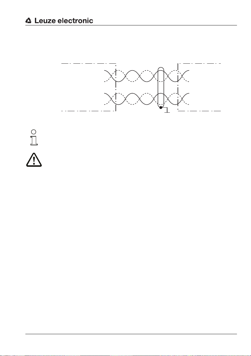
6.3.2 Connecting the SSI interface
Connection with MA
Figure 6.5: Connection with MA
26 BPS 37 Leuze electronic
Page 29
Installation
SSI DATA +
SSI DATA -
SSI Clock +
SSI Clock -
SSI DATA +
SSI DATA -
SSI Clock +
SSI Clock -
3
4
6
9
BPS 37 SM 100 Control/drive
SSI interface
Pin
Connection 1
Connection 2
Connection directly with BPS
Figure 6.6: Connection directly with BPS
Note!
Ensure adequate shielding. Connections 1 and 2 must be twisted in pairs and the entire
interconnection cable must be shielded, and earthed on one side.
Attention!
It is absolutely necessary to connect the protective conductor, since all electrical interference (EMC couplings) is discharged via the protective conductor connection.
Connecting the protective conductor PE
BPS 37 without cable: connect PE to the housing of the BPS 37 or to the
housing of the 15-pin SUB-D connector!
BPS 37 with cable KB 031-3000: connect PE to the wire with bl/wh color coding or
BPS with cable and MA 4.7 (MA 4D.7): connect PE to PIN 21 or PIN 22!
connect it to the shield!
Leuze electronic BPS 37 27
TNT 35/7-24V
Page 30

Installation
10 … 30 V
DC
12 … 30 V DC
SWIN12
SWOUT110
GND15
VIN8
max. 100 mA
6.3.3 Connecting the switching input and switching output
The BPS 37 is provided with a switching input and a switching output. The connection of the
switching input and output is made in accordance with Figure 6.7:
Figure 6.7: Connection diagram for switching input and switching output of the BPS 37
Switching input
In the standard setting you can use the switching input connection SWIN1 to reset the output
of the position measurement data to zero by applying a voltage of 12 … 30VDC between
SWIN1 (pin 2) and GND (pin 15).
Switching output
The switching output connection between SWOUT1 (pin 10) and GND (pin 15) is normally
open. In the standard setting, SWOUT1 is closed in the event of a positioning error.
You can configure the switching input and output according to your requirements, using the
28 BPS 37 Leuze electronic
supplied BPSConfig program.
Page 31

6.3.4 Connection with MS 37 103 modular connector hood
PWR = voltage supply, switching input, switching output
HOST/BUS IN = SSI interface
SERVICE = RS 232 service interface
Note!
The BUS OUT and SW IN/OUT connections are sealed
with caps.
Socket
(A-coded)
Plug
(B-coded)
Plug
(A-coded)
all dimensions in mm
The BPS 37 can be connected via the MS 37 103 using M12 connectors. For the locations
of the individual device connections, please refer to Figure 6.8.
SERVICE
BUS OUT
TXD
2
1
RXD
GND
3
4
/SERV
HOST/BUS IN PWR
3
CLK+
Installation
SW IN/OUT
D-
2
D+
1
GND
SWOUT
3
2
VIN
1
TNT 35/7-24V
STATUS
FE
4
CLK-
FE
4
SWIN
Figure 6.8: Pin assignment of the BPS 37 with MS 37 103
Attention!
Degree of protection IP 65 is achieved only if the connectors and caps are screwed into
place!
Leuze electronic BPS 37 29
Page 32

Installation
PWR
SWIN
SWOUT
3
2
1
4
GND VIN
FE
M12 plug
(A-coded)
PWR IN - voltage supply and switching input/output
Attention!
For devices with integrated heating, the supply voltage must be wired with a minimum
0.5mm
supply voltage through to other loads!
Note!
Cables with a wire cross section of 0.5mm² or 0.75mm² are not available as ready-made
cables from Leuze electronic.
Figure 6.9: Pin assignment - PWR IN
2
(recommended 0.75mm2) core cross section. It is not possible to loop the
PWR IN (5-pin plug, A-coded)
Pin Name Comment
Positive supply voltage
1VIN
Without optics heating: +10 … +30VDC
With optics heating: +22 … +26VDC
2 SWOUT Switching output
3 GND Negative supply voltage 0V DC
4 SWIN Switching input
5 FE Functional earth
Thread FE Functional earth (housing)
Connecting the functional earth FE
BPS 37 with MS 37 103 connector hood:
Connect FE to PIN 5 of the M12 connector PWR for voltage supply!
Attention!
Degree of protection IP 65 is achieved only if the connectors and caps are screwed into
place!
30 BPS 37 Leuze electronic
Page 33

Installation
HOST/BUS IN
SSI_CLK+
3
2
1
4
FE
SSI_D
-
SSI_CLK
-
SSI_D+
M12 plug
(B-coded)
SERVICE
1
2
3
4
n. c.
/SERV
RXD
TXD
GNDIN
M12 socket
(A-coded)
HOST/BUS IN - SSI interface
HOST / BUS IN (5-pin plug, B-coded)
Pin Name Comment
1 SSI_D+ SSI data line +
2 SSI_D- SSI data line -
3 SSI_CLK+ SSI clock line +
4 SSI_CLK- SSI clock line -
5FEFunctional earth
Thread FE Functional earth (housing)
Figure 6.10:Pin assignment - HOST/BUS IN
Attention!
Degree of protection IP 65 is achieved only if the connectors and caps are screwed into
place!
SERVICE - service interface
SW IN/OUT (5-pin socket, A-coded)
Pin Name Comment
1 n.c. Not assigned
2 TXD TXD signal, RS 232 service interface
3 GNDIN Reference ground RS 232
4 RXD RXD signal, RS 232 service interface
5 /SERV
Thread FE Functional earth (housing)
Figure 6.11:Pin assignment - SERVICE
Bridge to GND: service operation via
RS232 interface
TNT 35/7-24V
Attention!
Degree of protection IP 65 is achieved only if the connectors and caps are screwed into
place!
Leuze electronic BPS 37 31
Page 34

Installation
6.3.5 Cable lengths and shielding
The following maximum cable lengths and shielding types must be observed:
Connection Interface Max. cable length Shielding
BPS 37 - Service RS 232 10 m
BPS 37/MA 4.7 Host
Switching input 10 m Not necessary
Switching output 10 m Not necessary
Table 6.2: Cable lengths and shielding
SSI 1200 m
6.4 Disassembling, packing, disposing
Repacking
For later re-use, the device is to be packed so that it is protected against shocks and
humidity. Optimum protection is achieved when using the original packaging.
Note!
Electrical scrap is a special waste product! Observe the locally applicable regulations
regarding disposal of the product.
Absolutely required, sheath
of a shielded line
Absolutely required, leads
as twisted pairs and
shielded
32 BPS 37 Leuze electronic
Page 35

Commissioning
7 Commissioning
7.1 Measures to be performed prior to the initial commissioning
Before commissioning, familiarize yourself with the operation and configuration of the
device(s).
Before switch-on, recheck all connections and ensure that they have been properly
made.
7.2 Function Test
"Power On" test
After connecting the operating voltage, the BPS 37 performs an automatic "Power On" function test. Subsequently, the green LED lights up in the optical window of the BPS 37.
Interface
Proper function of the interface can be most easily tested in service operation using the
service interface with the "BPSConfig" configuration software and a notebook computer. For
order numbers, see Table 5.1 on page 17.
Online commands
Using the online commands, important device functions can be checked, e.g. proper functioning of the laser.
Problems
If a problem occurs that cannot be rectified even after checking all electrical connections and
settings on the devices and on the host, please contact the closest Leuze service organization (see back page of this operating manual).
7.3 Setting the parameters
You have now commissioned the BPS. Usually, you will have to configure it before you can
use it. Using the parameter options made available by the BPS, you can configure the BPS
to suit your individual area of application. For instructions regarding the various setting
options, refer to Chapter 9 or the online help for the BPSConfig program.
The setting is usually accomplished by using the program BPSConfig, see "Installing the
"BPSConfig" software" on page 37.
The various parameter sets are explained briefly in the following Chapter 7.3.1, to understand what is happening during parameter setting.
The setting of the parameters then takes place in the "service" operating mode, which is
described in Chapter 7.3.2.
Leuze electronic BPS 37 33
TNT 35/7-24V
Page 36

Commissioning
7.3.1 Parameter sets
In the BPS 37 three different parameter sets are administered:
• Parameter set with the factory settings in the ROM
• Current parameter set in EEPROM
• Working copy of the current parameter set in the RAM
Before a parameter set is loaded into the memory of the BPS 37 processor, the validity of
the parameter set is verified using check sums.
Factory default parameter set
This parameter set contains the factory-set default settings for all parameters of the BPS 37.
It is permanently stored in the ROM of the BPS 37. The parameter set with the default
settings is loaded into the memory of the BPS 37,
• the first time the device is commissioned after delivery
• following the command "Factory Default" in the configuration program
• if the check sums of the current parameter set are invalid.
Current parameter set
In this parameter set, the current settings for all device parameters are stored. When the
BPS 37 is in operation, the parameter set is stored in the EEPROM of the BPS 37. The
current set can be stored:
• by copying a valid parameter set from the host computer
• by means of an off-line setup with the PC setup program BPSConfig
The current parameter set is loaded into the memory of the BPS 37:
• always after connecting the supply voltage
• following a software reset
The current parameter set is overwritten by the parameter set with the factory settings:
• by a parameter reset, see "Online commands" on page 33
7.3.2 Service operating mode
Setting the required parameters is carried out easiest in the 'Service' operating mode. The
Service operating mode makes the following defined operating parameters available on a
separately wired RS 232 interface, independent from the BPS's configuration for standard
operation:
• transmission rate: 9600 baud
• no parity
• 8 data bits
• 1 stop bit
• prefix: STX
• postfix: CR, LF
34 BPS 37 Leuze electronic
Page 37

Commissioning
15 GND
12 TxD
11 RxD
BPSPC
Service
Activate service interface
The service interface is activated via a bridge between the pins 7 and 15 on the 15-pin
sub-D connector. If the BPS 37 is operated with a connection unit, the service interface is
activated through a switch in the connection unit.
Connect
You can connect a PC or terminal to the BPS 37 via the serial interface and configure the
BPS 37 through this connection. For this, you need a crossed RS 232 interconnection cable
(null modem cable) that provides the connections RxD, TxD and GND. A hardware handshake via RTS, CTS is not supported at the service interface.
If the BPS is connected to a connection unit, you can use the 9-pin SubD service connector
in the connection unit. For the respective pin assignments, please refer to the data sheet of
the connection unit.
Service operating mode
Figure 7.1: Connecting the service interface to a PC or terminal
Leuze electronic BPS 37 35
TNT 35/7-24V
Page 38

Operation
8 Operation
8.1 BPS 37 display elements
On the BPS 37 there is an LED which signals the BPS's readiness for operation.
8.2 MS 37 103 display elements
On the modular connector hood there is a status LED which indicates the state of the
device.
State Meaning
Off Voltage off
Green, flashing Initialization of the device
Green, continuous light Normal operation
Red Error
Orange, continuous light Service operation active
36 BPS 37 Leuze electronic
Page 39

9 Communication with the device
Device parameters can be set via commands or using the easy-to-use "BPSConfig 3.0"
control software.
9.1 Installing the "BPSConfig" software
Insert the installation CD in your CD drive.
Call up the installation file (e.g. Setup.exe)
The following window appears:
Installation window
Communication with the device
Figure 9.1: Installation window
Confirm the following license agreement and select the installation path in the following
window:
Leuze electronic BPS 37 37
TNT 35/7-24V
Page 40

Communication with the device
Installation directory
Figure 9.2: Installation directory
Confirm your entry with Next, then follow the installation routine.
For further details please refer to online help of the "BPSConfig" software.
38 BPS 37 Leuze electronic
Page 41

Communication with the device
9.2 Overview of commands and parameters
Online commands can be used to send commands directly to the device for control and
configuration.
For this, the BPS 37 has to be connected to a host or service computer via the serial interface. The commands described can be sent either via the host or the service interface.
9.2.1 General online commands
Command Description
M+ Activation of the measurement
M- Deactivation of the measurement
MI
MNx=yzzzzzzz
MNR
MMxyyyy
MM-
PC20
Reversing the counting direction
With the standard setting, the calculation is performed back from the max.
measurement length (10000 meter)
Set preset value
x = T = value is stored temporarily
(the value is erased after switching on and off)
x = D = value is stored permanently in the EPROM
y = sign for preset value
zzzzzzz = specification of the preset value in mm
Example: MND=+0001000
Current position is permanently set to +1000 mm.
Deactivates the preset value. The unformatted measurement value is
output.
Controls the data output via the service interface
x = S = a measurement value is output (Single Shot Mode); subsequent
specification of the time not necessary
x = T = measurement values are output cyclically; time must be subsequently specified
y = time specification in ms
Example: MMT0500
Measurement values are output via the service interface in a time interval
of 500ms
Deactivation of the MMTyyy function
If the cyclical output via the service interface is no longer required, the
function must be deactivated using the command MM-.
Resetting all parameters in the BPS 37 to Leuze default values.
Version query
TNT 35/7-24V
Leuze electronic BPS 37 39
Page 42

Communication with the device
The various setting options are contained in the measurement value
control folder. These are used for
activating or deactivating the measurement process.
Measurement value
control
Measurement value
preparation
This folder contains the parameters
which can be used to prepare the
measurement value. This includes
e.g. setting the initial or preset value,
the scaling setting, the counting
direction or the resolution.
Measurement value ranges can be
defined in this folder. If the measurement values rise above or drop
below these values, the BPS should
respond appropriately.
Measurement value
monitoring
In this folder the activation and
deactivation as well as the timing of
the switching output are defined.
Switching output
Settings can be made in this folder
for controlling how the BPS reacts
to the application of a 24 V signal.
Switching input
This folder contains all settings
necessary for integrating the BPS to
a control or drive system via an SSI
interface.
SSI interface
9.2.2 General parameter structure
Using the BPSConfig program, parameters can be changed via the service interface. These
parameters are divided into individual folders.
The following folders are available:
40 BPS 37 Leuze electronic
Page 43

10 Maintenance
10.1 General maintenance information
Usually, the bar code positioning system BPS 37 does not require any maintenance by the
operator.
Cleaning
Clean the glass window of the BPS 37 with a soft cloth when soiled.
Note!
Do not use aggressive cleaning agents such as thinner or acetone for cleaning the device.
10.2 Repairs, servicing
Repairs to the device must only be carried out by the manufacturer.
Contact your Leuze distributor or service organization should repairs be required.
For addresses, please refer to the back page of this operating manual.
Maintenance
Leuze electronic BPS 37 41
TNT 35/7-24V
 Loading...