

Page 1
BCL548i
Bar code reader
en 02-12/2012 50113410
We reserve the right to
make technical changes
TECHNICAL DESCRIPTION
Page 2

© 2013
Leuze electronic GmbH + Co. KG
In der Braike 1
D-73277 Owen / Germany
Phone: +49 7021 573-0
Fax: +49 7021 573-199
http://www.leuze.com
info@leuze.de
Leuze electronic BCL 548i
TNT 35/7-24V
Page 3

BCL 548i
LNK0
LNK1
Navigate
upward/laterally
Navigate
downward/laterally
ESCAPE
leave
ENTER
confirm
Device buttons:
Delete character
Enter digit
Save input
The main menus
ESC
Input of values
12|
<-|0123456789 save
Standard ----- Unit
126 | |
BCL548i SF 102
Leuze electronic
GmbH & Co. KG
SW: V 1.8.0 HW:3
SN: 1009A009815 001
IO1 IO2 IO3
IO4 ATT ERR
12345678
Parameter
Parameter handling
Decoder table
Digital SWIO
Ethernet
Language selection
o Deutsch
oEnglish
o Español
o Français
o Italiano
Ser vi ce
Diagnostics
Status messages
Device information - main menu
Information about
• Device type
• Software version
• Hardware version
• Serial number
Bar code reading window - main menu
Visualization of the read bar code information.
See "Indicators in the display" on page 89.
Parameter - main menu
Configuration of the bar code reader.
See "Parameter menu" on page 95.
Language selection - main menu
Selection of the display language.
See "Language selection menu" on page 104.
Service - main menu
Scanner diagnosis and status messages.
See "Service menu" on page 105.
Actions
o Start decoding
o Start alignment
o Start auto-setup
o Start teach-in
o Code recognition start
Actions main menu
Various functions for scanner configuration and
manual operation.
See "Actions menu" on page 105.
PWR LED BUS LED
Off Device OFF Off No supply voltage
Flashes green Device ok, initialization phase Flashes green Initialization
Green, continuous light Device OK Green, continuous light Operation OK
Orange, continuous light Service mode Flashes red Communication error
Flashes red Device ok, warning set Red, continuous light Network error
Red, continuous light Device error
Page 4

Table of contents
1 General information . . . . . . . . . . . . . . . . . . . . . . . . . . . . . . . . . . . 13
1.1 Explanation of symbols . . . . . . . . . . . . . . . . . . . . . . . . . . . . . . . . . . . . . . . . . . . . . . . . . . 13
1.2 Declaration of conformity . . . . . . . . . . . . . . . . . . . . . . . . . . . . . . . . . . . . . . . . . . . . . . . . 13
2 Safety notices. . . . . . . . . . . . . . . . . . . . . . . . . . . . . . . . . . . . . . . . 14
2.1 General safety notices . . . . . . . . . . . . . . . . . . . . . . . . . . . . . . . . . . . . . . . . . . . . . . . . . . . 14
2.2 Safety standards . . . . . . . . . . . . . . . . . . . . . . . . . . . . . . . . . . . . . . . . . . . . . . . . . . . . . . . 14
2.3 Approved purpose . . . . . . . . . . . . . . . . . . . . . . . . . . . . . . . . . . . . . . . . . . . . . . . . . . . . . . 14
2.4 Working safely . . . . . . . . . . . . . . . . . . . . . . . . . . . . . . . . . . . . . . . . . . . . . . . . . . . . . . . . . 15
3 Fast commissioning / operating principle . . . . . . . . . . . . . . . . . . . 17
3.1 Mounting the BCL 548i . . . . . . . . . . . . . . . . . . . . . . . . . . . . . . . . . . . . . . . . . . . . . . . . . . 17
3.2 Device arrangement and selection of the mounting location . . . . . . . . . . . . . . . . . . . . 17
3.3 Electrical connection BCL 548i . . . . . . . . . . . . . . . . . . . . . . . . . . . . . . . . . . . . . . . . . . . . 18
3.4 Starting the device. . . . . . . . . . . . . . . . . . . . . . . . . . . . . . . . . . . . . . . . . . . . . . . . . . . . . . 19
3.5 Commissioning the BCL 548i on the PROFINET-IO. . . . . . . . . . . . . . . . . . . . . . . . . . . . 19
3.5.1 Preparing the control system . . . . . . . . . . . . . . . . . . . . . . . . . . . . . . . . . . . . . . . . . . . . . . 19
3.5.2 Installing the GSD file . . . . . . . . . . . . . . . . . . . . . . . . . . . . . . . . . . . . . . . . . . . . . . . . . . . . 19
3.5.3 Configuration . . . . . . . . . . . . . . . . . . . . . . . . . . . . . . . . . . . . . . . . . . . . . . . . . . . . . . . . . . 20
3.5.4 Transfer of the configuration to the IO Controller . . . . . . . . . . . . . . . . . . . . . . . . . . . . . . . 20
3.5.5 Configuration of the device name - device naming . . . . . . . . . . . . . . . . . . . . . . . . . . . . . 21
3.5.6 Check device name . . . . . . . . . . . . . . . . . . . . . . . . . . . . . . . . . . . . . . . . . . . . . . . . . . . . . 22
3.6 Further settings . . . . . . . . . . . . . . . . . . . . . . . . . . . . . . . . . . . . . . . . . . . . . . . . . . . . . . . . 23
3.7 Bar code reading . . . . . . . . . . . . . . . . . . . . . . . . . . . . . . . . . . . . . . . . . . . . . . . . . . . . . . . 23
4 Device description . . . . . . . . . . . . . . . . . . . . . . . . . . . . . . . . . . . . 24
4.1 About the bar code readers of the BCL 500i series. . . . . . . . . . . . . . . . . . . . . . . . . . . . 24
4.2 Characteristics of the bar code readers of the BCL 500i series . . . . . . . . . . . . . . . . . . 25
4.4 Reading techniques . . . . . . . . . . . . . . . . . . . . . . . . . . . . . . . . . . . . . . . . . . . . . . . . . . . . . 28
4.4.1 Line scanner (single line). . . . . . . . . . . . . . . . . . . . . . . . . . . . . . . . . . . . . . . . . . . . . . . . . . 28
4.4.2 Line scanner with oscillating mirror . . . . . . . . . . . . . . . . . . . . . . . . . . . . . . . . . . . . . . . . . 29
4.4.3 Omnidirectional reading . . . . . . . . . . . . . . . . . . . . . . . . . . . . . . . . . . . . . . . . . . . . . . . . . . 30
4.5 Fieldbus systems . . . . . . . . . . . . . . . . . . . . . . . . . . . . . . . . . . . . . . . . . . . . . . . . . . . . . . . 31
4.5.1 PROFINET-IO . . . . . . . . . . . . . . . . . . . . . . . . . . . . . . . . . . . . . . . . . . . . . . . . . . . . . . . . . . 31
4.5.2 PROFINET-IO – star topology. . . . . . . . . . . . . . . . . . . . . . . . . . . . . . . . . . . . . . . . . . . . . . 33
4.5.3 PROFINET-IO – line topology . . . . . . . . . . . . . . . . . . . . . . . . . . . . . . . . . . . . . . . . . . . . . . 33
4.6 Heater . . . . . . . . . . . . . . . . . . . . . . . . . . . . . . . . . . . . . . . . . . . . . . . . . . . . . . . . . . . . . . . . 34
Leuze electronic BCL 548i 1
Page 5

Table of contents
4.7 External parameter memory. . . . . . . . . . . . . . . . . . . . . . . . . . . . . . . . . . . . . . . . . . . . . . . 34
4.8 autoReflAct . . . . . . . . . . . . . . . . . . . . . . . . . . . . . . . . . . . . . . . . . . . . . . . . . . . . . . . . . . . . 35
4.9 Reference codes. . . . . . . . . . . . . . . . . . . . . . . . . . . . . . . . . . . . . . . . . . . . . . . . . . . . . . . .35
4.10 autoConfig. . . . . . . . . . . . . . . . . . . . . . . . . . . . . . . . . . . . . . . . . . . . . . . . . . . . . . . . . . . . . 36
5 Specifications . . . . . . . . . . . . . . . . . . . . . . . . . . . . . . . . . . . . . . . . 37
5.1 General specifications of the bar code readers . . . . . . . . . . . . . . . . . . . . . . . . . . . . . . . 37
5.1.1 Line scanner . . . . . . . . . . . . . . . . . . . . . . . . . . . . . . . . . . . . . . . . . . . . . . . . . . . . . . . . . . . 37
5.1.2 Oscillating-mirror scanner . . . . . . . . . . . . . . . . . . . . . . . . . . . . . . . . . . . . . . . . . . . . . . . . .39
5.1.3 Line scanner with deflection mirror . . . . . . . . . . . . . . . . . . . . . . . . . . . . . . . . . . . . . . . . . . 39
5.2 Heating models of the bar code readers . . . . . . . . . . . . . . . . . . . . . . . . . . . . . . . . . . . . . 40
5.2.1 Line scanner with heating . . . . . . . . . . . . . . . . . . . . . . . . . . . . . . . . . . . . . . . . . . . . . . . . .41
5.2.2 Oscillating-mirror scanner with heating . . . . . . . . . . . . . . . . . . . . . . . . . . . . . . . . . . . . . . . 42
5.2.3 Line scanner with deflection mirror and heating . . . . . . . . . . . . . . . . . . . . . . . . . . . . . . . . 43
5.3 Dimensioned drawings . . . . . . . . . . . . . . . . . . . . . . . . . . . . . . . . . . . . . . . . . . . . . . . . . . . 44
5.3.1 Line scanner with / without heating . . . . . . . . . . . . . . . . . . . . . . . . . . . . . . . . . . . . . . . . . . 44
5.3.2 Deflection mirror scanner with / without heating. . . . . . . . . . . . . . . . . . . . . . . . . . . . . . . . 45
5.3.3 Oscillating-mirror scanner with / without heating . . . . . . . . . . . . . . . . . . . . . . . . . . . . . . . 46
5.4 Type overview BCL 548i. . . . . . . . . . . . . . . . . . . . . . . . . . . . . . . . . . . . . . . . . . . . . . . . . . 47
5.5 Reading field curves / optical data . . . . . . . . . . . . . . . . . . . . . . . . . . . . . . . . . . . . . . . . . 48
5.6 Reading field curves . . . . . . . . . . . . . . . . . . . . . . . . . . . . . . . . . . . . . . . . . . . . . . . . . . . . .49
5.6.1 High Density (N) Optics: BCL 548i SN 100/102 . . . . . . . . . . . . . . . . . . . . . . . . . . . . . . . . 50
5.6.2 High Density (N) Optics: BCL 548i ON 100 . . . . . . . . . . . . . . . . . . . . . . . . . . . . . . . . . . . . 51
5.6.3 Medium Density (M) Optics: BCL 548i SM 100/102 . . . . . . . . . . . . . . . . . . . . . . . . . . . . . 52
5.6.4 Medium Density (M) Optics: BCL 548i OM 100. . . . . . . . . . . . . . . . . . . . . . . . . . . . . . . . . 53
5.6.5 Low Density (F) Optics: BCL 548i SF 100/102 . . . . . . . . . . . . . . . . . . . . . . . . . . . . . . . . . 54
5.6.6 Low Density (F) Optics: BCL 548i OF 100 . . . . . . . . . . . . . . . . . . . . . . . . . . . . . . . . . . . . . 55
5.6.7 Ultra Low Density (L) Optics: BCL 548i SL 102. . . . . . . . . . . . . . . . . . . . . . . . . . . . . . . . . 56
5.6.8 Ultra Low Density (L) Optics: BCL 548i OL 100 . . . . . . . . . . . . . . . . . . . . . . . . . . . . . . . . 57
5.7 Reading field curves for heating devices . . . . . . . . . . . . . . . . . . . . . . . . . . . . . . . . . . . . 58
5.7.1 High Density (N) Optics: BCL 548i SN 102 H . . . . . . . . . . . . . . . . . . . . . . . . . . . . . . . . . . 58
5.7.2 High Density (N) Optics: BCL 548i SN 100 H . . . . . . . . . . . . . . . . . . . . . . . . . . . . . . . . . . 59
5.7.3 High Density (N) Optics: BCL 548i ON 100 H . . . . . . . . . . . . . . . . . . . . . . . . . . . . . . . . . . 60
5.7.4 Medium Density (M) Optics: BCL 548i SM 102 H . . . . . . . . . . . . . . . . . . . . . . . . . . . . . . . 61
5.7.5 Medium Density (M) Optics: BCL 548i SM 100 H . . . . . . . . . . . . . . . . . . . . . . . . . . . . . . . 62
5.7.6 Medium Density (M) Optics: BCL 548i OM 100 H . . . . . . . . . . . . . . . . . . . . . . . . . . . . . . . 63
5.7.7 Low Density (F) Optics: BCL 548i SF 102 H . . . . . . . . . . . . . . . . . . . . . . . . . . . . . . . . . . . 64
5.7.8 Low Density (F) Optics: BCL 548i SF 100 H . . . . . . . . . . . . . . . . . . . . . . . . . . . . . . . . . . . 65
5.7.9 Low Density (F) Optics: BCL 548i OF 100 H . . . . . . . . . . . . . . . . . . . . . . . . . . . . . . . . . . . 66
5.7.10 Ultra Low Density (L) Optics: BCL 548i SL 102 H . . . . . . . . . . . . . . . . . . . . . . . . . . . . . . . 67
5.7.11 Ultra Low Density (L) Optics: BCL 548i OL 100 H . . . . . . . . . . . . . . . . . . . . . . . . . . . . . . . 68
2 BCL 548i Leuze electronic
Page 6

Table of contents
6 Installation and mounting . . . . . . . . . . . . . . . . . . . . . . . . . . . . . . . 69
6.1 Storage, transportation . . . . . . . . . . . . . . . . . . . . . . . . . . . . . . . . . . . . . . . . . . . . . . . . . . 69
6.2 Mounting the BCL 548i . . . . . . . . . . . . . . . . . . . . . . . . . . . . . . . . . . . . . . . . . . . . . . . . . . 70
6.2.1 Fastening with M4 x 6 screws . . . . . . . . . . . . . . . . . . . . . . . . . . . . . . . . . . . . . . . . . . . . . 70
6.2.2 BT 56 mounting device. . . . . . . . . . . . . . . . . . . . . . . . . . . . . . . . . . . . . . . . . . . . . . . . . . . 71
6.2.3 BT 59 mounting device. . . . . . . . . . . . . . . . . . . . . . . . . . . . . . . . . . . . . . . . . . . . . . . . . . . 73
6.3 Device arrangement. . . . . . . . . . . . . . . . . . . . . . . . . . . . . . . . . . . . . . . . . . . . . . . . . . . . . 74
6.3.1 Selecting a mounting location . . . . . . . . . . . . . . . . . . . . . . . . . . . . . . . . . . . . . . . . . . . . . 74
6.3.2 Avoiding total reflection – Line scanner . . . . . . . . . . . . . . . . . . . . . . . . . . . . . . . . . . . . . . 75
6.3.3 Avoiding total reflection – oscillating/deflection-mirror scanner. . . . . . . . . . . . . . . . . . . . 75
6.3.4 Mounting location . . . . . . . . . . . . . . . . . . . . . . . . . . . . . . . . . . . . . . . . . . . . . . . . . . . . . . . 76
6.3.5 Devices with integrated heating . . . . . . . . . . . . . . . . . . . . . . . . . . . . . . . . . . . . . . . . . . . . 76
6.3.6 Possible read angles between BCL 548i and bar code . . . . . . . . . . . . . . . . . . . . . . . . . . 77
6.4 Attaching laser warning sign . . . . . . . . . . . . . . . . . . . . . . . . . . . . . . . . . . . . . . . . . . . . . . 77
6.5 Cleaning . . . . . . . . . . . . . . . . . . . . . . . . . . . . . . . . . . . . . . . . . . . . . . . . . . . . . . . . . . . . . . 77
7 Electrical connection . . . . . . . . . . . . . . . . . . . . . . . . . . . . . . . . . . 78
7.1 Safety notices for the electrical connection . . . . . . . . . . . . . . . . . . . . . . . . . . . . . . . . . . 78
7.2 Electrical connection of the BCL 548i . . . . . . . . . . . . . . . . . . . . . . . . . . . . . . . . . . . . . . 79
7.2.1 PWR – Voltage supply and switching input/outputs 3 and 4 . . . . . . . . . . . . . . . . . . . . . . 80
7.2.2 SERVICE – USB interface (type A) . . . . . . . . . . . . . . . . . . . . . . . . . . . . . . . . . . . . . . . . . . 82
7.2.3 SW IN/OUT – Switching input/switching output. . . . . . . . . . . . . . . . . . . . . . . . . . . . . . . . 83
7.2.4 HOST / BUS IN for BCL 548i . . . . . . . . . . . . . . . . . . . . . . . . . . . . . . . . . . . . . . . . . . . . . . 85
7.2.5 BUS OUT for the BCL 548i . . . . . . . . . . . . . . . . . . . . . . . . . . . . . . . . . . . . . . . . . . . . . . . . 86
7.3 PROFINET-IO topologies. . . . . . . . . . . . . . . . . . . . . . . . . . . . . . . . . . . . . . . . . . . . . . . . . 87
7.3.1 PROFINET-IO wiring . . . . . . . . . . . . . . . . . . . . . . . . . . . . . . . . . . . . . . . . . . . . . . . . . . . . . 88
7.4 Cable lengths and shielding . . . . . . . . . . . . . . . . . . . . . . . . . . . . . . . . . . . . . . . . . . . . . . 88
8 Display and control panel . . . . . . . . . . . . . . . . . . . . . . . . . . . . . . . 89
8.1 Structure of the control panel . . . . . . . . . . . . . . . . . . . . . . . . . . . . . . . . . . . . . . . . . . . . . 89
8.2 Status display and operation . . . . . . . . . . . . . . . . . . . . . . . . . . . . . . . . . . . . . . . . . . . . . 89
8.2.1 Indicators in the display . . . . . . . . . . . . . . . . . . . . . . . . . . . . . . . . . . . . . . . . . . . . . . . . . . 89
8.2.2 LED status indicators . . . . . . . . . . . . . . . . . . . . . . . . . . . . . . . . . . . . . . . . . . . . . . . . . . . . 90
8.2.3 Control buttons . . . . . . . . . . . . . . . . . . . . . . . . . . . . . . . . . . . . . . . . . . . . . . . . . . . . . . . . . 91
8.3 Menu description . . . . . . . . . . . . . . . . . . . . . . . . . . . . . . . . . . . . . . . . . . . . . . . . . . . . . . . 93
8.3.2 Parameter menu . . . . . . . . . . . . . . . . . . . . . . . . . . . . . . . . . . . . . . . . . . . . . . . . . . . . . . . . 95
8.3.3 Language selection menu. . . . . . . . . . . . . . . . . . . . . . . . . . . . . . . . . . . . . . . . . . . . . . . . 104
8.3.4 Service menu . . . . . . . . . . . . . . . . . . . . . . . . . . . . . . . . . . . . . . . . . . . . . . . . . . . . . . . . . 105
8.3.5 Actions menu . . . . . . . . . . . . . . . . . . . . . . . . . . . . . . . . . . . . . . . . . . . . . . . . . . . . . . . . . 105
8.4 Operation . . . . . . . . . . . . . . . . . . . . . . . . . . . . . . . . . . . . . . . . . . . . . . . . . . . . . . . . . . . . 107
Leuze electronic BCL 548i 3
Page 7

Table of contents
9 Leuze webConfig tool . . . . . . . . . . . . . . . . . . . . . . . . . . . . . . . . . 110
9.1 Connecting the SERVICE USB interface . . . . . . . . . . . . . . . . . . . . . . . . . . . . . . . . . . . . 110
9.2 Installing the required software . . . . . . . . . . . . . . . . . . . . . . . . . . . . . . . . . . . . . . . . . . . 111
9.2.1 System requirements. . . . . . . . . . . . . . . . . . . . . . . . . . . . . . . . . . . . . . . . . . . . . . . . . . . . 111
9.2.2 Installing the USB driver . . . . . . . . . . . . . . . . . . . . . . . . . . . . . . . . . . . . . . . . . . . . . . . . . 111
9.3 Starting the webConfig tool . . . . . . . . . . . . . . . . . . . . . . . . . . . . . . . . . . . . . . . . . . . . . . 113
9.4 Short description of the webConfig tool . . . . . . . . . . . . . . . . . . . . . . . . . . . . . . . . . . . . 114
9.4.1 Module overview in the Configuration menu . . . . . . . . . . . . . . . . . . . . . . . . . . . . . . . . . . 114
10 Commissioning and configuration . . . . . . . . . . . . . . . . . . . . . . . . 116
10.1 General information on the PROFINET-IO implementation of the BCL 548i . . . . . . . . 116
10.1.1 PROFINET-IO communication profile . . . . . . . . . . . . . . . . . . . . . . . . . . . . . . . . . . . . . . . 116
10.1.2 Conformance Classes . . . . . . . . . . . . . . . . . . . . . . . . . . . . . . . . . . . . . . . . . . . . . . . . . . . 117
10.2 Measures to be performed prior to the initial commissioning . . . . . . . . . . . . . . . . . . . 117
10.3 Starting the device . . . . . . . . . . . . . . . . . . . . . . . . . . . . . . . . . . . . . . . . . . . . . . . . . . . . . 118
10.4 Configuration steps for a Siemens Simatic S7 control . . . . . . . . . . . . . . . . . . . . . . . . . 118
10.4.1 Step 1 – Preparing the control system (S7 PLC) . . . . . . . . . . . . . . . . . . . . . . . . . . . . . . .118
10.4.2 Step 2 – Installation of the GSD file . . . . . . . . . . . . . . . . . . . . . . . . . . . . . . . . . . . . . . . . . 119
10.4.3 Step 3 – Hardware configuration of the S7 PLC: Configuration . . . . . . . . . . . . . . . . . . . 120
10.4.4 Step 4 – Transfer of the configuration to the IO Controller (S7 PLC) . . . . . . . . . . . . . . . 121
10.4.5 Step 5 – Configuration of the device name - naming the device . . . . . . . . . . . . . . . . . . 121
10.4.6 Step 6 – Check device names . . . . . . . . . . . . . . . . . . . . . . . . . . . . . . . . . . . . . . . . . . . . . 123
10.4.7 Ethernet host communication . . . . . . . . . . . . . . . . . . . . . . . . . . . . . . . . . . . . . . . . . . . . . 124
10.4.7.1 Manually setting the IP address............................................................................................................124
10.4.7.2 Automatically setting the IP address ....................................................................................................125
10.4.7.3 TCP/IP ...................................................................................................................................................126
10.4.7.4 UDP.......................................................................................................................................................128
10.5 Commissioning via the PROFINET-IO . . . . . . . . . . . . . . . . . . . . . . . . . . . . . . . . . . . . . . 129
10.5.1 General information . . . . . . . . . . . . . . . . . . . . . . . . . . . . . . . . . . . . . . . . . . . . . . . . . . . . . 129
10.6 Overview of the project modules . . . . . . . . . . . . . . . . . . . . . . . . . . . . . . . . . . . . . . . . . .134
10.7 Decoder modules . . . . . . . . . . . . . . . . . . . . . . . . . . . . . . . . . . . . . . . . . . . . . . . . . . . . . . 137
10.7.1 Modules 1-4 – Code table extensions 1 to 4. . . . . . . . . . . . . . . . . . . . . . . . . . . . . . . . . . 137
10.7.2 Module 5 – Code type features (symbology) . . . . . . . . . . . . . . . . . . . . . . . . . . . . . . . . . . 139
10.7.3 Module 7 – Code fragment technology . . . . . . . . . . . . . . . . . . . . . . . . . . . . . . . . . . . . . . 140
10.8 Control modules . . . . . . . . . . . . . . . . . . . . . . . . . . . . . . . . . . . . . . . . . . . . . . . . . . . . . . . 141
10.8.1 Module 10 – Activations . . . . . . . . . . . . . . . . . . . . . . . . . . . . . . . . . . . . . . . . . . . . . . . . . 141
10.8.2 Module 11 – Reading gate control. . . . . . . . . . . . . . . . . . . . . . . . . . . . . . . . . . . . . . . . . . 143
10.8.3 Module 12 – Multi-label . . . . . . . . . . . . . . . . . . . . . . . . . . . . . . . . . . . . . . . . . . . . . . . . . . 145
10.8.4 Module 13 – Fragmented read result. . . . . . . . . . . . . . . . . . . . . . . . . . . . . . . . . . . . . . . . 146
10.8.5 Module 14 – Interlinked read result . . . . . . . . . . . . . . . . . . . . . . . . . . . . . . . . . . . . . . . . . 147
4 BCL 548i Leuze electronic
Page 8

Table of contents
10.9 Result Format. . . . . . . . . . . . . . . . . . . . . . . . . . . . . . . . . . . . . . . . . . . . . . . . . . . . . . . . . 148
10.9.1 Module 20 – Decoder state. . . . . . . . . . . . . . . . . . . . . . . . . . . . . . . . . . . . . . . . . . . . . . . 148
10.9.2 Modules 21-27 – Decoding result. . . . . . . . . . . . . . . . . . . . . . . . . . . . . . . . . . . . . . . . . . 150
10.9.3 Module 30 – Data formatting . . . . . . . . . . . . . . . . . . . . . . . . . . . . . . . . . . . . . . . . . . . . . 152
10.9.4 Module 31 – Reading gate number . . . . . . . . . . . . . . . . . . . . . . . . . . . . . . . . . . . . . . . . 153
10.9.5 Module 32 – Reading gate time . . . . . . . . . . . . . . . . . . . . . . . . . . . . . . . . . . . . . . . . . . . 154
10.9.6 Module 33 – Code position. . . . . . . . . . . . . . . . . . . . . . . . . . . . . . . . . . . . . . . . . . . . . . . 154
10.9.7 Module 34 – Reading reliability (equal scans). . . . . . . . . . . . . . . . . . . . . . . . . . . . . . . . . 155
10.9.8 Module 35 – Bar code length . . . . . . . . . . . . . . . . . . . . . . . . . . . . . . . . . . . . . . . . . . . . . 155
10.9.9 Module 36 – Scans with information . . . . . . . . . . . . . . . . . . . . . . . . . . . . . . . . . . . . . . . 156
10.9.10 Module 37 – Decoding quality . . . . . . . . . . . . . . . . . . . . . . . . . . . . . . . . . . . . . . . . . . . . 156
10.9.11 Module 38 – Code direction . . . . . . . . . . . . . . . . . . . . . . . . . . . . . . . . . . . . . . . . . . . . . . 157
10.9.12 Module 39 – Number of digits . . . . . . . . . . . . . . . . . . . . . . . . . . . . . . . . . . . . . . . . . . . . 157
10.9.13 Module 40 – Code type (symbology) . . . . . . . . . . . . . . . . . . . . . . . . . . . . . . . . . . . . . . . 158
10.9.14 Module 41 – Code position in the swivel range . . . . . . . . . . . . . . . . . . . . . . . . . . . . . . . 159
10.10 Data Processing . . . . . . . . . . . . . . . . . . . . . . . . . . . . . . . . . . . . . . . . . . . . . . . . . . . . . . . 160
10.10.1 Module 50 – Characteristics filter . . . . . . . . . . . . . . . . . . . . . . . . . . . . . . . . . . . . . . . . . . 160
10.10.2 Module 51 – Data filtering . . . . . . . . . . . . . . . . . . . . . . . . . . . . . . . . . . . . . . . . . . . . . . . . 162
10.11 Identifier . . . . . . . . . . . . . . . . . . . . . . . . . . . . . . . . . . . . . . . . . . . . . . . . . . . . . . . . . . . . . 163
10.11.1 Module 52 – Segmentation according to the EAN process . . . . . . . . . . . . . . . . . . . . . . 163
10.11.2 Module 53 – Segmentation via fixed positions . . . . . . . . . . . . . . . . . . . . . . . . . . . . . . . . 165
10.11.3 Module 54 – Segmentation according to identifier and separator . . . . . . . . . . . . . . . . . 168
10.11.4 Module 55 – String handling parameters . . . . . . . . . . . . . . . . . . . . . . . . . . . . . . . . . . . . 170
10.12 Device Functions . . . . . . . . . . . . . . . . . . . . . . . . . . . . . . . . . . . . . . . . . . . . . . . . . . . . . . 171
10.12.1 Module 60 – Device status . . . . . . . . . . . . . . . . . . . . . . . . . . . . . . . . . . . . . . . . . . . . . . . 171
10.12.2 Module 61 – Laser control . . . . . . . . . . . . . . . . . . . . . . . . . . . . . . . . . . . . . . . . . . . . . . . 172
10.12.3 Module 62 – Display . . . . . . . . . . . . . . . . . . . . . . . . . . . . . . . . . . . . . . . . . . . . . . . . . . . . 173
10.12.4 Module 63 – Alignment . . . . . . . . . . . . . . . . . . . . . . . . . . . . . . . . . . . . . . . . . . . . . . . . . . 174
10.12.5 Module 64 – Oscillating mirror . . . . . . . . . . . . . . . . . . . . . . . . . . . . . . . . . . . . . . . . . . . . 175
10.12.6 Module 65 – Deflection mirrors. . . . . . . . . . . . . . . . . . . . . . . . . . . . . . . . . . . . . . . . . . . . 176
10.13 Switching inputs/ outputs SWIO 1 … 4 . . . . . . . . . . . . . . . . . . . . . . . . . . . . . . . . . . . . 176
10.13.1 Parameters for operating as an output . . . . . . . . . . . . . . . . . . . . . . . . . . . . . . . . . . . . . . 176
10.13.2 Parameters for operating as an input . . . . . . . . . . . . . . . . . . . . . . . . . . . . . . . . . . . . . . . 178
10.13.3 Switch-on and switch-off functions for operation as an output . . . . . . . . . . . . . . . . . . . 180
10.13.4 Input functions for operation as an input . . . . . . . . . . . . . . . . . . . . . . . . . . . . . . . . . . . . 180
10.13.5 Module 70 – Switching input/output SWIO1 . . . . . . . . . . . . . . . . . . . . . . . . . . . . . . . . . 181
10.13.6 Module 71 – Switching input/output SWIO2 . . . . . . . . . . . . . . . . . . . . . . . . . . . . . . . . . 183
10.13.7 Module 72 – Switching input/output SWIO3 . . . . . . . . . . . . . . . . . . . . . . . . . . . . . . . . . 185
10.13.8 Module 73 – Switching input/output SWIO4 . . . . . . . . . . . . . . . . . . . . . . . . . . . . . . . . . 187
10.13.9 Module 74 – SWIO status and control . . . . . . . . . . . . . . . . . . . . . . . . . . . . . . . . . . . . . . 189
10.14 Data output . . . . . . . . . . . . . . . . . . . . . . . . . . . . . . . . . . . . . . . . . . . . . . . . . . . . . . . . . . 191
10.14.1 Module 80 – Sorting . . . . . . . . . . . . . . . . . . . . . . . . . . . . . . . . . . . . . . . . . . . . . . . . . . . . 191
Leuze electronic BCL 548i 5
Page 9

Table of contents
10.15 Reference code comparison . . . . . . . . . . . . . . . . . . . . . . . . . . . . . . . . . . . . . . . . . . . . . 192
10.15.1 Module 81 – Reference code comparator 1 . . . . . . . . . . . . . . . . . . . . . . . . . . . . . . . . . . 192
10.15.2 Module 82 – Reference code comparator 2 . . . . . . . . . . . . . . . . . . . . . . . . . . . . . . . . . . 194
10.15.3 Module 83 – Reference code comparison pattern 1 . . . . . . . . . . . . . . . . . . . . . . . . . . . . 196
10.15.4 Module 84 – Reference code comparison pattern 2 . . . . . . . . . . . . . . . . . . . . . . . . . . . . 197
10.16 Special Functions . . . . . . . . . . . . . . . . . . . . . . . . . . . . . . . . . . . . . . . . . . . . . . . . . . . . . . 198
10.16.1 Module 90 – Status and control. . . . . . . . . . . . . . . . . . . . . . . . . . . . . . . . . . . . . . . . . . . . 198
10.16.2 Module 91 – AutoReflAct (automatic reflector activation) . . . . . . . . . . . . . . . . . . . . . . . . 199
10.16.3 Module 92 – AutoControl. . . . . . . . . . . . . . . . . . . . . . . . . . . . . . . . . . . . . . . . . . . . . . . . . 200
10.17 Example configuration: Indirect activation via the PLC . . . . . . . . . . . . . . . . . . . . . . . . 201
10.17.1 Task . . . . . . . . . . . . . . . . . . . . . . . . . . . . . . . . . . . . . . . . . . . . . . . . . . . . . . . . . . . . . . . . . 201
10.17.2 Procedure . . . . . . . . . . . . . . . . . . . . . . . . . . . . . . . . . . . . . . . . . . . . . . . . . . . . . . . . . . . . 201
10.18 Sample configuration: Direct activation via the switching input . . . . . . . . . . . . . . . . .203
10.18.1 Task . . . . . . . . . . . . . . . . . . . . . . . . . . . . . . . . . . . . . . . . . . . . . . . . . . . . . . . . . . . . . . . . . 203
10.18.2 Procedure . . . . . . . . . . . . . . . . . . . . . . . . . . . . . . . . . . . . . . . . . . . . . . . . . . . . . . . . . . . . 203
11 Online commands . . . . . . . . . . . . . . . . . . . . . . . . . . . . . . . . . . . . 205
11.1 Overview of commands and parameters. . . . . . . . . . . . . . . . . . . . . . . . . . . . . . . . . . . . 205
11.1.1 General 'online' commands. . . . . . . . . . . . . . . . . . . . . . . . . . . . . . . . . . . . . . . . . . . . . . . 206
12 Diagnostics and troubleshooting . . . . . . . . . . . . . . . . . . . . . . . . . 223
13 Type overview and accessories . . . . . . . . . . . . . . . . . . . . . . . . . . 227
13.1 Type key . . . . . . . . . . . . . . . . . . . . . . . . . . . . . . . . . . . . . . . . . . . . . . . . . . . . . . . . . . . . . 227
13.2 Type overviewBCL 548i . . . . . . . . . . . . . . . . . . . . . . . . . . . . . . . . . . . . . . . . . . . . . . . . . 227
13.3 Accessory connectors . . . . . . . . . . . . . . . . . . . . . . . . . . . . . . . . . . . . . . . . . . . . . . . . . . 228
13.4 Accessory USB cable . . . . . . . . . . . . . . . . . . . . . . . . . . . . . . . . . . . . . . . . . . . . . . . . . . . 228
13.5 Accessory external parameter memory. . . . . . . . . . . . . . . . . . . . . . . . . . . . . . . . . . . . . 229
13.6 Accessory mounting device . . . . . . . . . . . . . . . . . . . . . . . . . . . . . . . . . . . . . . . . . . . . . . 229
13.7 Accessory reflector for AutoReflAct . . . . . . . . . . . . . . . . . . . . . . . . . . . . . . . . . . . . . . . 229
13.8 Accessory ready-made cables for voltage supply . . . . . . . . . . . . . . . . . . . . . . . . . . . . 230
13.8.1 Contact assignment of PWR connection cable . . . . . . . . . . . . . . . . . . . . . . . . . . . . . . . . 230
13.8.2 Specifications of the cables for voltage supply . . . . . . . . . . . . . . . . . . . . . . . . . . . . . . . . 230
13.8.3 Order codes of the cables for voltage supply . . . . . . . . . . . . . . . . . . . . . . . . . . . . . . . . . 230
13.9 Accessory ready-made cables for bus connection . . . . . . . . . . . . . . . . . . . . . . . . . . . 231
13.9.1 General information . . . . . . . . . . . . . . . . . . . . . . . . . . . . . . . . . . . . . . . . . . . . . . . . . . . . . 231
13.9.2 Contact assignments M12 PROFINET-IO connection cable KB ET… . . . . . . . . . . . . . . 231
13.9.3 Specifications M12 PROFINET-IO connection cable KB ET… . . . . . . . . . . . . . . . . . . . .231
13.9.4 Order codes M12 PROFINET-IO connection cable KB ET… . . . . . . . . . . . . . . . . . . . . . 232
6 BCL 548i Leuze electronic
Page 10

Table of contents
14 Maintenance . . . . . . . . . . . . . . . . . . . . . . . . . . . . . . . . . . . . . . . . 233
14.1 General maintenance information . . . . . . . . . . . . . . . . . . . . . . . . . . . . . . . . . . . . . . . . . 233
14.2 Repairs, servicing . . . . . . . . . . . . . . . . . . . . . . . . . . . . . . . . . . . . . . . . . . . . . . . . . . . . . 233
14.3 Disassembling, packing, disposing . . . . . . . . . . . . . . . . . . . . . . . . . . . . . . . . . . . . . . . 233
15 Appendix. . . . . . . . . . . . . . . . . . . . . . . . . . . . . . . . . . . . . . . . . . . 234
15.1 Declaration of conformity . . . . . . . . . . . . . . . . . . . . . . . . . . . . . . . . . . . . . . . . . . . . . . . 234
15.2 ASCII character set . . . . . . . . . . . . . . . . . . . . . . . . . . . . . . . . . . . . . . . . . . . . . . . . . . . . 235
15.3 Bar code samples . . . . . . . . . . . . . . . . . . . . . . . . . . . . . . . . . . . . . . . . . . . . . . . . . . . . . 239
15.3.1 Module 0.3 . . . . . . . . . . . . . . . . . . . . . . . . . . . . . . . . . . . . . . . . . . . . . . . . . . . . . . . . . . . 239
15.3.2 Module 0.5 . . . . . . . . . . . . . . . . . . . . . . . . . . . . . . . . . . . . . . . . . . . . . . . . . . . . . . . . . . . 240
Leuze electronic BCL 548i 7
Page 11

Figures and tables
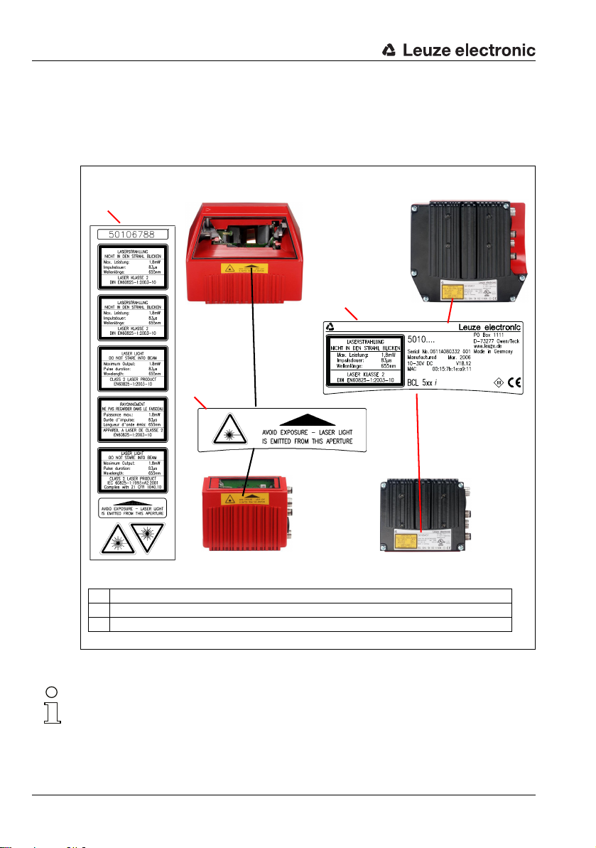
Figure 2.1: Attachment of the stick-on labels with warning notices at the BCL 548i........................ 16
Figure 3.1: Connections of the BCL 548i......................................................................................... 18
Figure 3.2: Assignment of the device names to IP addresses .......................................................... 20
Figure 3.3: Assigning the device names to the configured IO devices.............................................. 21
Figure 3.4: MAC address - IP address -individual device name ....................................................... 22
Figure 4.1: Line scanner, line scanner with deflection mirror and oscillating-mirror scanner........... 24
Figure 4.2: Possible bar code orientation ........................................................................................26
Figure 4.3: Device construction ......................................................................................................27
Figure 4.4: Deflection principle for the line scanner ........................................................................ 28
Figure 4.5: Deflection principle for the line scanner with oscillating mirror add-on.......................... 29
Figure 4.6: Principle arrangement for omnidirectional reading ........................................................ 30
Table 4.1: Base record I&M0 .........................................................................................................32
Figure 4.7: PROFINET-IO in a star topology ..................................................................................... 33
Figure 4.8: PROFINET-IO in a line topology...................................................................................... 33
Figure 4.9: External parameter memory.......................................................................................... 34
Figure 4.10: Reflector arrangement for autoReflAct .......................................................................... 35
Table 5.1: Specifications of the BCL 548i line scanners without heating ........................................ 37
Table 5.2: Specifications of the BCL 548i oscillating-mirror scanners without heating ................... 39
Table 5.3: Specifications of the BCL 548i deflection-mirror scanners without heating.................... 39
Table 5.4: Specifications of the BCL 548i line scanners with heating ............................................. 41
Table 5.5: Specifications of the BCL 548i oscillating-mirror scanners with heating ........................ 42
Table 5.6: Specifications of the BCL 548i deflection-mirror scanners with heating ........................ 43
Figure 5.1: Dimensioned drawing BCL 548i line scanner S…102................................................... 44
Figure 5.2: Dimensioned drawing BCL 548i deflection-mirror scanner S…100............................... 45
Figure 5.3: Dimensioned drawing BCL 548i oscillating-mirror scanner O…100.............................. 46
Table 5.7: Type overview BCL 548i ............................................................................................... 47
Figure 5.4: The most important characteristics of a bar code.......................................................... 48
Figure 5.5: Zero position of the reading distance ............................................................................49
Table 5.8: Reading conditions ....................................................................................................... 49
Figure 5.6: "High Density" reading field curve for line scanner (with/without deflection mirror)....... 50
Figure 5.7: "High Density" reading field curve for oscillating-mirror scanners................................. 51
Figure 5.8: Lateral "High Density" reading field curve for oscillating-mirror scanners ..................... 51
Figure 5.9: "Medium Density" reading field curve for line scanner (with/without deflection mirror) . 52
Figure 5.10: "Medium Density" reading field curve for oscillating-mirror scanners ........................... 53
Figure 5.11: Lateral "Medium Density" reading field curve for oscillating-mirror scanners................ 53
Figure 5.12: "Low Density" reading field curve for line scanner (with/without deflection mirror) ....... 54
Figure 5.13: "Low Density" reading field curve for oscillating-mirror scanners ................................. 55
Figure 5.14: Lateral "Low Density" reading field curve for oscillating-mirror scanners...................... 55
Figure 5.15: "Ultra Low Density" reading field curve for line scanner without deflection mirror ......... 56
Figure 5.16: "Ultra Low Density" reading field curve for oscillating-mirror scanners .........................57
Figure 5.17: Lateral "Ultra Low Density" reading field curve for oscillating-mirror scanners.............. 57
Figure 5.18: "High Density" reading field curve for line scanner with heating (without deflection mirror).58
Figure 5.19: "High Density" reading field curve for line scanner with heating (with deflection mirror)......59
Figure 5.20: "High Density" reading field curve for oscillating-mirror scanners with heating............. 60
8 BCL 548i Leuze electronic
Page 12

Figures and tables
Figure 5.21: Lateral "High Density" reading field curve for oscillating-mirror scanners with heating . 60
Figure 5.22: "Medium Density" reading field curve for line scanner with heating (without deflection mirror) 61
Figure 5.23: "Medium Density" reading field curve for line scanner with heating (with deflection mirror) .. 62
Figure 5.24: "Medium Density" reading field curve for oscillating-mirror scanners with heating ....... 63
Figure 5.25: Lateral "Medium Density" reading field curve for oscillating-mirror scanners with heating.. 63
Figure 5.26: "Low Density" reading field curve for line scanner with heating (without deflection mirror). 64
Figure 5.27: "Low Density" reading field curve for line scanner with heating (with deflection mirror) ....65
Figure 5.28: "Low Density" reading field curve for oscillating-mirror scanners with heating ............. 66
Figure 5.29: Lateral "Low Density" reading field curve for oscillating-mirror scanners with heating.. 66
Figure 5.30: "Ultra Low Density" reading field curve for line scanner with heating (without deflection mirror)...67
Figure 5.31: "Ultra Low Density" reading field curve for oscillating-mirror scanners with heating..... 68
Figure 5.32: Lateral "Ultra Low Density" reading field curve for oscillating-mirror scanners with heating. 68
Figure 6.1: Device name plate BCL 548i......................................................................................... 69
Figure 6.2: Fastening options using M4x6 threaded holes .............................................................. 70
Figure 6.3: BT 56 mounting device................................................................................................. 71
Figure 6.4: Mounting example of BCL 548i with BT 56 ................................................................... 72
Figure 6.5: Total reflection – line scanner....................................................................................... 75
Figure 6.6: Total reflection – BCL 548i with oscillating/deflection mirror......................................... 76
Figure 6.7: Reading angle for the line scanner................................................................................ 77
Figure 7.1: Location of the electrical connections ........................................................................... 78
Figure 7.2: Connections of the BCL 548i......................................................................................... 79
Table 7.1: Pin assignment PWR..................................................................................................... 80
Figure 7.3: Switching input connection diagram SWIO_3 and SWIO_4............................................ 81
Figure 7.4: Switching output connection diagram SWIO_3 / SWIO_4 .............................................. 81
Figure 7.5: Pin assignments of SERVICE – USB interface ................................................................ 82
Figure 7.6: Pin assignment SW IN/OUT ........................................................................................... 83
Figure 7.7: Switching input connection diagram SWIO_1 and SWIO_2............................................ 83
Figure 7.8: Switching output connection diagram SWIO_1 / SWIO_2 .............................................. 84
Table 7.2: Pin assignment HOST / BUS IN BCL 548i ...................................................................... 85
Figure 7.9: HOST / BUS IN cable assignments on RJ-45 ................................................................. 85
Table 7.3: Pin assignment BUS OUT .............................................................................................. 86
Figure 7.10: PROFINET-IO in a star topology ..................................................................................... 87
Figure 7.11: PROFINET-IO in a line topology ..................................................................................... 87
Table 7.4: Cable lengths and shielding .......................................................................................... 88
Figure 8.1: Structure of the control panel........................................................................................ 89
Table 8.1: Parameter handling submenu ....................................................................................... 95
Table 8.2: Decoder table submenu ................................................................................................ 96
Table 8.3: Digital SWIO submenu ..................................................................................................99
Table 8.4: Ethernet submenu ...................................................................................................... 102
Figure 9.1: Connecting the SERVICE USB interface ....................................................................... 110
Figure 9.2: Device Manager with connected BCL 500i.................................................................. 112
Figure 9.3: The start page of the webConfig tool........................................................................... 113
Figure 9.4: Module overview in the webConfig tool....................................................................... 114
Figure 10.1: Connections of the BCL 548i....................................................................................... 117
Leuze electronic BCL 548i 9
Page 13

Figures and tables
Table 10.1: Assignment of the device names to IP addresses ........................................................120
Figure 10.2: Assigning the device names to the configured IO devices............................................ 122
Figure 10.3: MAC address - IP address -individual device name ..................................................... 123
Table 10.2: Device parameters ...................................................................................................... 130
Table 10.3: Module overview......................................................................................................... 135
Table 10.4: Parameters for modules 1-4 ....................................................................................... 137
Table 10.5: Parameters for module 5 ............................................................................................ 139
Table 10.6: Parameters for module 7 ............................................................................................ 140
Table 10.7: Parameters for module 10 .......................................................................................... 141
Table 10.8: Output data for module 10 ..........................................................................................141
Table 10.9: Parameters for module 11 .......................................................................................... 143
Table 10.10: Parameters for module 12 .......................................................................................... 145
Table 10.11: Input data for module 12............................................................................................. 145
Table 10.12: Parameters for module 13 .......................................................................................... 146
Table 10.13: Input data for module 13............................................................................................. 146
Table 10.14: Parameters for module 13 .......................................................................................... 147
Table 10.15: Input data for module 20............................................................................................. 148
Table 10.16: Input data for modules 21 … 27................................................................................. 150
Table 10.17: Parameters for module 30 .......................................................................................... 152
Table 10.18: Input data for module 31............................................................................................. 153
Table 10.19: Input data for module 32............................................................................................. 154
Table 10.20: Input data for module 33............................................................................................. 154
Table 10.21: Input data for module 34............................................................................................. 155
Table 10.22: Input data for module 35............................................................................................. 155
Table 10.23: Input data for module 36............................................................................................. 156
Table 10.24: Input data for module 37............................................................................................. 156
Table 10.25: Input data for module 38............................................................................................. 157
Table 10.26: Input data for module 39............................................................................................. 157
Table 10.27: Input data for module 40............................................................................................. 158
Table 10.28: Input data for module 41............................................................................................. 159
Table 10.29: Parameters for module 50 .......................................................................................... 160
Table 10.30: Parameters for module 51 .......................................................................................... 162
Table 10.31: Parameters for module 52 .......................................................................................... 163
Table 10.32: Parameters for module 53 .......................................................................................... 165
Table 10.33: Parameters for module 54 .......................................................................................... 168
Table 10.34: Parameters for module 55 .......................................................................................... 170
Table 10.35: Input data for module 60............................................................................................. 171
Table 10.36: Output data for module 60 .......................................................................................... 171
Table 10.37: Parameters for module 61 .......................................................................................... 172
Table 10.38: Parameters for module 62 .......................................................................................... 173
Table 10.39: Input data for module 63............................................................................................. 174
Table 10.40: Output data for module 63 .......................................................................................... 174
Table 10.41: Parameters for module 64 .......................................................................................... 175
Table 10.42: Parameters for module 65 .......................................................................................... 176
10 BCL 548i Leuze electronic
Page 14

Figures and tables
Figure 10.4: Example 1: Start-up delay > 0 and switch-on time = 0............................................... 177
Figure 10.5: Example 2: Start-up delay > 0 and switch-on time > 0............................................... 177
Figure 10.6: Example 3: Start-up delay >0 Switch-off signal prior to lapsing of the
start-up delay ............................................................................................................. 177
Figure 10.7: Start-up delay in input mode....................................................................................... 178
Figure 10.8: Switch-on time in input mode..................................................................................... 179
Figure 10.9: Switch-off delay in input mode ................................................................................... 179
Table 10.43: Switch-on/switch-off functions................................................................................... 180
Table 10.44: Input functions............................................................................................................ 180
Table 10.45: Parameters for module 70 – Input/Output 1................................................................ 181
Table 10.46: Parameters for module 71 – Input/Output 2................................................................ 183
Table 10.47: Parameters for module 72 – Input/Output 3................................................................ 185
Table 10.48: Parameters for module 73 – Input/Output 4................................................................ 187
Table 10.49: Input data for module 74 Input/output status and control ............................................ 189
Table 10.50: Output data for module 74 Input/output status and control.......................................... 190
Table 10.51: Parameters for module 80 .......................................................................................... 191
Table 10.52: Parameters for module 81 – Reference code comparison ........................................... 192
Table 10.53: Parameters for module 82 – Reference code comparison ........................................... 194
Table 10.54: Parameter module 83 – Reference code comparison pattern ...................................... 196
Table 10.55: Parameter module 84 – Reference code comparison pattern ...................................... 197
Table 10.56: Input data for module 90 – Status and control ............................................................ 198
Table 10.57: Parameters for module 91 – AutoreflAct ..................................................................... 199
Table 10.58: Parameters for module 92 – AutoControl .................................................................... 200
Table 10.59: Input data for module 92 – AutoControl....................................................................... 200
Table 10.60: Device parameters for example configuration 2 .......................................................... 203
Table 12.1: BCL 548i alarm and diagnostics messages ................................................................. 224
Table 12.2: BCL 548i error categories ........................................................................................... 224
Table 12.1: General causes of errors ............................................................................................. 225
Table 12.1: Interface error............................................................................................................. 225
Table 13.1: Type overview BCL 548i ............................................................................................. 227
Table 13.2: Connectors for the BCL 548i ....................................................................................... 228
Table 13.3: Cable for the BCL 548i ................................................................................................ 228
Table 13.4: External parameter memory for the BCL 548i ............................................................. 229
Table 13.5: Mounting devices for the BCL 548i ............................................................................. 229
Table 13.6: Reflector for the BCL 548i........................................................................................... 229
Table 13.7: PWR cables for the BCL 548i ...................................................................................... 230
Figure 13.1: Cable configuration PROFINET-IO connection cable..................................................... 231
Table 13.8: Bus connection cable for the BCL 548i ....................................................................... 232
Figure 15.1: Bar code sample labels (module 0.3) .......................................................................... 239
Figure 15.2: Bar code sample labels (module 0.5) .......................................................................... 240
Leuze electronic BCL 548i 11
Page 15

1 General information
1.1 Explanation of symbols
The symbols used in this technical description are explained below.
Attention!
This symbol precedes text messages which must strictly be observed. Failure to comply with
this information results in injuries to personnel or damage to the equipment.
Attention Laser!
This symbol warns of possible danger caused by hazardous laser radiation.
Notice!
This symbol indicates text passages containing important information.
1.2 Declaration of conformity
The bar code readers of the BCL 500i series have been developed and manufactured in
accordance with the applicable European standards and directives.
The BCL 500i series is "UL LISTED" according to American and Canadian safety standards,
and fulfills the requirements of Underwriter Laboratories Inc. (UL).
General information
Notice!
You can find the Declaration of Conformity of the devices in the appendix of the manual on
page 234.
The manufacturer of the product, Leuze electronic GmbH & Co KG in D-73277 Owen,
possesses a certified quality assurance system in accordance with ISO 9001.
U
L
C
US
LISTED
Leuze electronic BCL 548i 13
TNT 35/7-24V
Page 16

Safety notices
2 Safety notices
2.1 General safety notices
Documentation
All entries in this technical description must be heeded, in particular the present chapter
"Safety notices". Keep this technical description in a safe place. It should be available at all
times.
Safety regulations
Observe the locally applicable regulations and the rules of the employer's liability insurance
association.
Repair
Repairs must only be carried out by the manufacturer or an authorized representative.
2.2 Safety standards
The bar code readers of the BCL 500i series were developed, manufactured and tested in
accordance with the applicable safety standards. They correspond to the state of the art.
2.3 Approved purpose
Attention!
The protection of personnel and the device cannot be guaranteed if the device is operated
in a manner not complying with its intended use.
Bar code readers of the BCL 500i series are conceived as stationary, high-speed scanners
with integrated decoders for all current bar codes used for automatic object detection.
In particular, unauthorized uses include:
• in rooms with explosive atmospheres
• operation for medical purposes
Areas of application
The bar code readers of the BCL 500i series are especially designed for the following areas
of application:
• Storage and conveying technologies, in particular for object identification on fastmoving conveyor belts
• Pallet transportation applications
• Automobile sector
• Omnidirectional reading
14 BCL 548i Leuze electronic
Page 17

2.4 Working safely
Attention!
Access to or changes on the device, except where expressly described in this operating manual, are not authorized.
Safety regulations
Observe the locally applicable legal regulations and the rules of the employer's liability insurance association.
Qualified personnel
Mounting, commissioning and maintenance of the device must only be carried out by qualified personnel.
Electrical work must be carried out by a certified electrician.
Attention, laser radiation!
If you look into the beam path over a longer time period, the retina of your eye may
be damaged!
Never look directly into the beam path!
Do not point the laser beam of the BCL 548i at persons!
When mounting and aligning the BCL 548i, avoid reflections of the laser beam off
reflective surfaces!
The BCL 548i bar code readers comply with safety standards EN 60825-1 for a class
2 product. They also comply with the U.S. 21 CFR 1040.10 regulations for a class II
laser product except for deviations pursuant to Laser Notice No. 50, dated July 26,
2001.
Radiant Energy: The BCL 548i uses a low power visible laser diode. The emitted wavelength is 655nm. The average laser power is less than 1mW in accordance with the
definition of class 2 lasers.
Adjustments: Do not attempt any adjustments to or alterations of this product.
Do not remove the protective housing of the bar code reader. There are no userserviceable parts inside.
The scanner window is the only aperture through which light may be observed on this
product. A failure of the scanner motor, while the laser diode continues to emit a laser
beam, may cause emission levels to exceed those for safe operation. The bar code
reader has safeguards to prevent this occurrence. If, however, a stationary beam is
emitted, the failing bar code reader should be disconnected from its power source
immediately.
Safety notices
TNT 35/7-24V
CAUTION: Use of controls or adjustments or performance of procedures other than
specified herein may result in hazardous light exposure.
Leuze electronic BCL 548i 15
Page 18
Safety notices
A
B
BCL 548i
Line scanner
BCL 548i
with oscillating/deflection mirror
C
A Included stick-on labels
B Aperture label
C Name plate
The use of optical instruments or devices in combination with the device increases
the danger of eye damage!
The housing of the BCL 548i is provided with warning notices B and C above and next
to the reading window as shown in the following figure:
Figure 2.1: Attachment of the stick-on labels with warning notices at the BCL 548i
Notice!
It is important that you attach the stick-on labels supplied to the device (A in figure 2.1)! If
the signs would be covered due to the installation situation of the BCL 548i, attach them
instead in the immediate vicinity of the BCL 548i in such a way that it is not necessary to
look into the laser beam when reading the notices!
16 BCL 548i Leuze electronic
Page 19

Fast commissioning / operating principle
3 Fast commissioning / operating principle
Below you will find a short description for the initial commissioning of the BCL 548i. Detailed
explanations for all listed points can be found throughout this technical description.
3.1 Mounting the BCL 548i
There are two different types of mounting arrangements for the BCL 548i:
• Using two M4x6 screws on the rear of the device or using four M4x6 screws on the
bottom of the device.
• Using a BT 56 mounting device on the two fastening grooves.
3.2 Device arrangement and selection of the mounting location
In order to select the right mounting location, several factors must be considered:
• Size, orientation, and position tolerance of the bar codes on the objects to be scanned.
• The reading field of the BCL 548i in relation to the bar code module width.
• The resulting minimum and maximum reading distance from the respective reading
field (see chapter 5.5 "Reading field curves / optical data").
• The permissible cable lengths between the BCL 548i and the host system depending
on which interface is used.
• The correct time for data output. The BCL 548i should be positioned in such a way
that, taking into consideration the time required for data processing and the conveyor
belt speed, there is sufficient time to e.g. initiate sorting operations on the basis of the
read data.
• The display and control panel should be very visible and accessible.
• For configuring and commissioning with the webConfig tool, the USB interface should
be easily accessible.
For specific information, please refer to chapter 4.4.
Notice!
The beam exits the BCL 548i as follows for the respective devices:
- line scanner parallel to the housing base
- oscillating mirror and deflection mirror perpendicular to the housing base
The black areas in figure 6.1 are the housing base. The best read results are obtained when:
• The BCL 548i is mounted in such a way that the scanning beam is incident on the bar
code at an angle of inclination greater than ±10° … 15° to vertical.
• The reading distance lies in the middle area of the reading field.
• The bar code labels are of good print quality and have good contrast ratios.
• You do not use high-gloss labels.
• There is no direct sunlight.
Leuze electronic BCL 548i 17
TNT 35/7-24V
Page 20

Fast commissioning / operating principle
SW IN/OUT
VOUT
1
2
3
4
SWIO_1
SWIO_2
GND
FE
5
HOST / BUS IN
TD+
1
2
3
4
RD+
RD-
TD-
SERVICE
2134
GND D+ D-
U
B
PWR
SWIO_4
SWIO_3
3
2
1
4
5
GND VIN
FE
BUS OUT
TD+
1
2
3
4
RD+
RD-
TD-
USB socket
Type A
M12 socket
(A-coded)
M12 socket
(D-coded)
M12 socket
(D-coded)
M12 plug
(A-coded)
3.3 Electrical connection BCL 548i
The BCL 548i is equipped with four M12 connectors/sockets which are A- and D-coded.
Figure 3.1: Connections of the BCL 548i
The voltage supply (10 … 30 VDC) is connected at the PWR M12 connector.
Available at both the PWR M12 connector as well as at the SW IN/OUT M12 socket are
four freely programmable switching inputs/outputs for custom adaptation to the
respective application. Detailed information on this topic can be found in chapter 7.2.1 and
chapter 7.2.3.
Standalone operation in PROFINET-IO
During stand-alone operation of the BCL 548i, the host interface of the superior system is
connected to HOST/BUS IN. Thus, a star structure (Ethernet structure) is possible.
Network operation in PROFINET-IO
In network operation, the superior system (PC/PLC) is connected to the host interface of
the BCL 548i. With the aid of the "switch" integrated in the BCL 548i, the bus connection
to the next participant, e.g. a BCL 548i, can occur directly via the BUS OUT socket! In addition to the classic "star topology", a "linear topology" is thus also possible
18 BCL 548i Leuze electronic
Page 21

3.4 Starting the device
LNK0
LNK1
Connect the supply voltage +10 … 30V DC (typ. +24 V DC); the BCL 548i starts up and
the bar code reading window appears on the display:
Fast commissioning / operating principle
First, you need to assign its individual device name to the BCL 548i. The PLC must communicate this device name to the participant during the "device naming". Further information
may be found below and in chapter "Step 5 – Configuration of the device name - naming
the device" on page 121.
By default, parameter enabling is deactivated and you cannot change
any settings. If you wish to carry out the configuration via the display,
you must activate parameter enabling. Further information can be found
in chapter "Parameter enabling" on page 107.
3.5 Commissioning the BCL 548i on the PROFINET-IO
Complete the necessary steps for commissioning a Siemens-S7 control as described
below.
Further information regarding the individual commissioning steps is provided in see chapter
10.4 "Configuration steps for a Siemens Simatic S7 control".
3.5.1 Preparing the control system
In the first step, assign an IP address to the IO Controller (S7 PLC) and prepare the control
for a consistent data transmission.
Notice!
If an S7 control is used, you need to ensure that Simatic-Manager Version 5.4 + service
pack 5 (V5.4+SP5) or higher is used.
3.5.2 Installing the GSD file
For the subsequent configuration of the IO devices, e.g., BCL 548i, the corresponding GSD
file must be loaded first. All data in modules required for operating the BCL 548i is described
in this file. These are input and output data and device parameters for the functioning of the
BCL 548i and the definition of the control and status bits.
Install the GSD file associated with the BCL 548i in the PROFINET-IO Manager of your
control.
TNT 35/7-24V
Leuze electronic BCL 548i 19
Page 22

Fast commissioning / operating principle
3.5.3 Configuration
Configure the PROFINET-IO system with the HW Config of the SIMATIC Manager by
inserting the BCL 548i into your project.
Figure 3.2: Assignment of the device names to IP addresses
Here, an IP address is assigned to a unique "device name".
3.5.4 Transfer of the configuration to the IO Controller
Transfer the PROFINET-IO configuration to the IO Controller (S7 PLC).
After the correct transfer to the IO Controller (S7 PLC), the PLC automatically carries
out the following activities:
• Check device names
• Assignment of the IP addresses that were configured in the HW Config to the
IO devices
• Establishment of a connection between the IO Controller and configured IO devices
• Cyclical data exchange
Notice!
Participants that have not been "named" cannot be contacted yet at this point in time!
20 BCL 548i Leuze electronic
Page 23

Fast commissioning / operating principle
3.5.5 Configuration of the device name - device naming
PROFINET-IO defines the "naming of the device" as the creation of a name-based relationship for a PROFINET-IO device.
Assigning the device names to the configured IO devices
Select the respective bar code scanner BCL 548i for the "device naming" based on its
MAC address.
The unique "device name" (which must match the participant in the HW Config) is then
assigned to this participant.
Notice!
Multiple BCL 548i can be distinguished by the MAC addresses displayed. The MAC address
may be found on the name plate of the respective bar code scanner.
Figure 3.3: Assigning the device names to the configured IO devices
Leuze electronic BCL 548i 21
TNT 35/7-24V
Page 24

Fast commissioning / operating principle
Assignment of MAC address - IP address -individual device name
At this point, assign an IP address (suggested by the PLC), a subnet mask and, if required,
a router address, and assign this data to the named participant ("device name").
Figure 3.4: MAC address - IP address -individual device name
From now on, and when programming, only the unique "device name" (max. 255 characters)
is used.
3.5.6 Check device name
After completing the configuration phase, recheck the "device names" that have been
assigned. Please ensure that these names are unique and that all participants are located
in the same subnet.
22 BCL 548i Leuze electronic
Page 25

3.6 Further settings
Modul 0,5
6677889900
Carry out further settings via the PROFINET-IO Controller, such as the control of the
decoding and processing of the read data and the configuration of the connected switching
inputs and outputs, using the parameters provided by the GSD file.
Activate the desired modules (at least module 10 and one of the modules 21 … 27).
A detailed description of the modules can be found beginning on chapter 10.6.
3.7 Bar code reading
With the aid of the "Action menu", you can instruct the BCL 548i to read a bar code.
Fast commissioning / operating principle
Actions
o Start decoding
o Start alignment
o Start auto-setup
o Start teach-in
To test, you can use the following bar code in the 2/5 Interleaved format. The bar code
module here is 0.5:
The read information appears in the display and is simultaneously passed on to the superior
system (PLC or PC).
Please check the incoming data of the bar code information there.
Alternatively, you can connect a photoelectric sensor or a 24 V DC switching signal to the
SW IN/OUT socket for read activation. To do this, however, you must appropriately
configure the switching input (see chapter 7.2.3 "SW IN/OUT – Switching input/switching
output").
In the main menu, use the buttons to select the Actions menu
item. Activate the Actions menu with . Then select Start decod-
ing with and press again to start the bar code reading oper-
ation.
TNT 35/7-24V
Leuze electronic BCL 548i 23
Page 26

Device description
Line scanner
Oscillating-mirror scanner /
Line scanner with deflection mirror
4 Device description
4.1 About the bar code readers of the BCL 500i series
Bar code readers of the BCL 500i series are high-speed scanners with integrated decoder
for all commonly used bar codes, e.g. 2/5 Interleaved, Code 39, Code 128, EAN 8/13 etc.,
as well as codes from the GS1 DataBar family.
Bar code readers of the BCL 500i series are available in various optics models as well as
line scanners, line scanners with deflection mirrors, oscillating mirrors and also optionally
as heated models.
Figure 4.1: Line scanner, line scanner with deflection mirror and oscillating-mirror scanner
The extensive options for device configuration via display or software enable adaptation to
a multitude of reading tasks. Due to the large reading distance combined with the great
depth of field and a very compact construction, the device is ideally suited for package and
pallet transportation systems. In general, the bar code readers of the BCL 500i series are
designed for the conveyor and storage technology market.
The interfaces (RS 232, RS 485 and RS 422) integrated in the various device models and
24 BCL 548i Leuze electronic
the fieldbus systems (PROFIBUS DP, PROFINET-IO and Ethernet) of the bar code readers
of the BCL 500i series offer optimum connection to the superior host system.
Page 27

Device description
4.2 Characteristics of the bar code readers of the BCL 500i series
Performance features:
• Integrated fieldbus connectivity = i -> Plug-and-Play fieldbus coupling and easy
networking
• Numerous interface variants facilitate connection to the superior systems
• RS 232, RS 422 as well as with integrated multiNet plus master
• RS 485 and multiNet plus slave
alternatively, various fieldbus systems, such as
•PROFIBUS DP
•PROFINET-IO
•Ethernet
• Integrated code fragment technology (CRT) enables the identification of soiled or damaged bar codes
• Maximum depth of field and reading distances from 200mm to 2400mm
• Large optical opening angle and, thus, large reading field width
• High scanning rate from 800 - 1200 scans/s for fast reading tasks
• Intuitive, backlit, multi-language display with user-friendly menu navigation
•Integrated USB 1.1 service interface
• Adjustment of all device parameters with a web browser
• Connection options for an external parameter memory
• Easy alignment- and diagnosis functions
• M12 connections with Ultra-Lock™ technology
• Four freely programmable switching inputs/outputs for the activation or signaling of
states
• Automatic monitoring of the read quality with autoControl
• Automatic recognition and setting of the bar code type using autoConfig
• Reference code comparison
• Optional heating models to -35°C
• Heavy-duty housing of protection class IP 65
Notice!
Information on technical data and characteristics can be found in chapter 5.
General information
The integrated fieldbus connectivity = i contained in the bar code readers of the BCL 500i
series facilitates the use of identification systems which function without connector unit or
gateways. The integrated fieldbus interface considerably simplifies handling. The Plug-andPlay concept enables easy networking and very simple commissioning: Directly connect the
respective fieldbus and all configuration is performed with no additional software.
For decoding bar codes, the bar code readers of the BCL 500i series make available the
proven CRT decoder with code fragment technology:
Leuze electronic BCL 548i 25
TNT 35/7-24V
Page 28

Device description
The proven code fragment technology (CRT) enables bar code readers of the BCL 500i
series to read bar codes with a small bar height, as well as bar codes with a damaged or
soiled print image.
With the aid of the CRT decoder, bar codes can also be read without problem in other
demanding situations, such as with a large tilt angle (azimuth angle or even twist angle).
Figure 4.2: Possible bar code orientation
With the BCL 548i, configuration is generally performed with the aid of the GSD file.
The BCL 548i needs a suitable activation to start a read process as soon as an object is in
the reading field. This opens a time window ("reading gate") in the BCL 548i for the read
process during which the bar code reader has time to detect and decode a bar code.
In the basic setting, triggering takes place through an external reading cycle signal.
Alternative activation options include online commands via the host interface and the
autoReflAct function.
Through the read operation, the BCL 548i collects additional useful pieces of data for diagnosis which can also be transmitted to the host. The quality of the read operation can be
inspected using the alignment mode which is integrated in the webConfig tool.
A multi-language display with buttons is used to operate the BCL 548i as well as for visualization purposes. Two LEDs provide additional optical information on the current operating
state of the device.
The four freely configurable switching inputs/outputs "SWIO 1 … SWIO 4" can be assigned
various functions and control e.g. activation of the BCL 548i or external devices, such as a
PLC.
System, warning and error messages provide assistance in setup/troubleshooting during
commissioning and read operation.
26 BCL 548i Leuze electronic
Page 29

4.3 Device construction
USB interface
M12 connection
technology
Reading window
Dovetail mounting and
4 mounting threads
Dovetail mounting and
2 mounting threads
Display, LEDs
and buttons
Figure 4.3: Device construction
Device description
Leuze electronic BCL 548i 27
TNT 35/7-24V
Page 30

Device description
4.4 Reading techniques
4.4.1 Line scanner (single line)
A line (scan line) scans the label. Due to the opt. opening angle, the reading field width is
dependent on the read distance. Through the movement of the object, the entire bar code
is automatically transported through the scan line.
The integrated code fragment technology permits twisting of the bar code (tilt angle) within
certain limits. These are dependent on the transport speed, the scanning rate of the scanner
and the bar code properties.
Areas of application of the line scanner
The line scanner is used:
• when the bars of the bar code are printed in the conveying direction
('ladder arrangement').
• with bar codes having very short bar lengths.
• when the ladder code is turned out of the vertical position (tilt angle).
• when the scanning distance is large.
Figure 4.4: Deflection principle for the line scanner
28 BCL 548i Leuze electronic
Page 31

4.4.2 Line scanner with oscillating mirror
The oscillating mirror deflects the scan line additionally to both sides across the scan direction at a randomly adjustable oscillation frequency. In this way, the BCL 548i can also scan
larger areas or spaces for bar codes. The reading field height (and the scan line length useful
for evaluation) depends on the reading distance due to the optical beam width of the oscillating mirror.
Areas of application of the line scanner with oscillating mirror
For line scanners with oscillating mirror, oscillation frequency, start/stop position etc. are
adjustable. It is used:
• when the position of the label is not fixed, e.g. on pallets – various labels can, thus,
be detected at various positions.
• when the bars of the bar code are printed perpendicular to the conveying direction
('picket fence arrangement').
• when reading stationary objects.
• when the bar code is turned out of the horizontal position.
• when the scanning distance is large.
• when a large reading field (reading window) has to be covered.
Device description
Figure 4.5: Deflection principle for the line scanner with oscillating mirror add-on
Leuze electronic BCL 548i 29
TNT 35/7-24V
Page 32

Device description
4.4.3 Omnidirectional reading
In order to read arbitrarily oriented bar codes on an object, at least 2 bar code readers are
necessary. If the bar code is not printed over-square, i.e. bar length > code length, bar code
readers with integrated code fragment technology are necessary.
Figure 4.6: Principle arrangement for omnidirectional reading
30 BCL 548i Leuze electronic
Page 33

4.5 Fieldbus systems
Various product variants of the BCL 500i series are available for connecting to different
fieldbus systems such as PROFIBUS DP, PROFINET-IO and Ethernet.
4.5.1 PROFINET-IO
The BCL 548i is designed as a PROFINET-IO device (acc. to IEEE 802.3). It supports a transmission rate of up to 100 Mbit/s (100Base TX/FX), full duplex, as well as auto-negotiation
and auto-crossover.
The functionality of the device is defined via parameter sets which are clustered in modules.
These modules are contained in a GSDML file.
Each BCL 548i is sealed with a unique MAC-ID. This information is used to assign a unique,
plant-specific device name ("NameOfStation") to the device via the "Discovery and Configuration Protocol (DCP)". When configuring a PROFINET-IO system, the assignment of the
device names to the configured IO devices creates a name-based relationship for the participating IO devices ("device naming"). Further information can be found in section "Commissioning and configuration" on page 116.
The BCL 548i features multiple M12 connectors / sockets for the electrical connection of
the supply voltage, the interface and the switching inputs and outputs. Additional information on the electrical connection can be found in chapter 7.
The BCL 548i supports:
• PROFIBUS-IO device functionality based on the PROFIBUS profile for identification
systems
• Modular structure of the IO data
•PROFINET-IO RT (Real Time) communication
• Standard Fast Ethernet (100 Mbit/s) connections (M12 technology)
• Integrated Ethernet switch/ 2 Ethernet ports
• PROFINET-IO Conformance Class B (CC-B)
• I&M support: I&M 0-4
• Diagnostics/alarms
Device description
TNT 35/7-24V
For further details, see chapter 10!
Leuze electronic BCL 548i 31
Page 34

Device description
Identification & Maintenance Functions
The BCL 548i supports the base record I&M0:
Contents Index Data type Description Value
Header 0 10 bytes
MANUFACTURER_ID 10 UNSIGNED16
ORDER_ID 12 ASCII string 20 bytes Leuze order no.
SERIAL_NUMBER 32 ASCII string 16 bytes Unique device serial number Device-dependent
HARDWARE_REVISION 48 UNSIGNED16
SOFTWARE_REVISION 50 1xCHAR, 3xUNSIGNED8
REVISION_COUNTER 54 UNSIGNED16
PROFILE_ID 56 UNSIGNED16 PROFIBUS application profile number
PROFILE_SPECIFIC_TYPE 58 UNSIGNED16
IM_VERSION 60 2xUNSIGNED8 Implemented I&M version V 1.1 0x01,0x01
IM_SUPPORTED 62 Bit[16] Optional I&M records available 0
Table 4.1: Base record I&M0
The BCL 548i supports further protocols and services for communication:
• TCP / IP (Client / Server)
•UDP
•DCP
•ARP
•PING
Further information on commissioning can be found in chapter 10.
Manufacturer specific
Manufacturer specific
Leuze PNO manufacturer ID
Leuze manufacturer ID
Hardware revision number, e.g.
"0…65535"
Software version number, e.g. V130
correspond to "V1.3.0"
Is incremented when updating individual
modules. This function is not supported
Info about subchannels and submodules
Not relevant
338
Device-dependent
Device-dependent
0
0xF600 (Generic
Device)
0x01,0x01
32 BCL 548i Leuze electronic
Page 35

4.5.2 PROFINET-IO – star topology
PC / PLC host interface
Other network participants
BCL 548i
"myBCL 548i_1"
PC / PLC host interface
BCL 548i
"myBCL 548i_1"
to other network participants
BCL 548i
"myBCL 548i_2"
BCL 548i
"myBCL 548i_3
The BCL 548i can be operated as a single device (standalone) with individual device name
in a star topology. The PLC must communicate this device name to the participant during
the "device naming".
Figure 4.7: PROFINET-IO in a star topology
4.5.3 PROFINET-IO – line topology
The innovative further development of the BCL 548i with integrated switch functionality
offers the option of connecting multiple bar code readers of type BCL 548i to one another
without direct connection to a switch. In addition to the classic "star topology", a "linear
topology" is thus also possible.
Device description
Leuze electronic BCL 548i 33
Figure 4.8: PROFINET-IO in a line topology
Each participant in this network requires its own unique device name that is assigned by
the PLC during the "device naming". For specific information, please refer to chapter "Step
5 – Configuration of the device name - naming the device" on page 121.
The maximum length of a segment (connection from the hub to the last participant) is limited
to 100m.
TNT 35/7-24V
Page 36

Device description
USB memory stick
4.6 Heater
For low-temperature applications to min. -35°C (e.g. in cold storage), the bar code readers
of the BCL 548i series can optionally be permanently fitted with a built-in heating and these
bar code readers purchased as separate device models.
4.7 External parameter memory
The optionally available external parameter memory –
based on a USB memory stick (compatible with
version 1.1) – is housed in an external hood with
integrated connectors which cover the USB service
interface when installed (IP 65).
The external parameter memory simplifies the timesaving onsite exchange of a BCL 548i by providing a
copy of the current parameter set of the BCL 548i and
by storing the device name as well. This eliminates the
need to configure the exchanged device manually
and, in particular, a new naming of the device – the
control can immediately access the exchanged
BCL 548i.
The delivery contents of the external parameter memory include the hood with integrated
connectors with unscrewable cover and the USB memory stick.
Figure 4.9: External parameter memory
Notice!
To mount, the cover of the service interface must be unscrewed. Then take the USB memory
stick and plug it into the USB connection on the BCL 548i. Then, take the connector hood
of the USB memory stick and screw this over the plugged-in USB memory stick to the service
interface to close the system and ensure protection class IP 65.
34 BCL 548i Leuze electronic
Page 37

4.8 autoReflAct
AutoReflAct stands for Automatic Reflector Activation and permits an activation without
additional sensors. This is achieved by directing the scanner with reduced scanning beam
towards a reflector mounted behind the conveyor path. As long as the scanner is targeted
at the reflector, the reading gate remains closed. If, however, the reflector is blocked by an
object such as a container with a bar code label, the scanner activates the read procedure,
and the label on the container is read. When the path from the scanner to the reflector has
cleared, the read procedure has completed and the scanning beam is reduced and again
directed onto the reflector. The reading gate is closed.
Notice!
You will find a matching reflector in Accessories, and more are available on request.
Device description
Figure 4.10: Reflector arrangement for autoReflAct
The autoReflAct function uses the scanning beam to simulate a photoelectric sensor and
thus permits an activation without additional sensory mechanism.
4.9 Reference codes
The BCL 548i offers the possibility of storing one or two reference codes.
It is possible to store the reference codes by means of teach-in (display command), via the
webConfig tool, via online commands or PROFINET-IO.
The BCL 548i can compare read bar codes with one and/or both reference codes and
execute user-configurable functions depending on the comparison result.
Leuze electronic BCL 548i 35
TNT 35/7-24V
Page 38

Device description
4.10 autoConfig
With the autoConfig function, the BCL 548i offers the user who only wishes to simultaneously read one code type (symbology) with one number of digits an extremely simple and
convenient configuration option.
After starting the autoConfig function via the display, switching input or from a superior
control, it is sufficient to position a bar code label with the desired code type and number
of digits in the reading field of the BCL 548i.
Afterward, bar codes with the same code type and number of digits are recognized and
decoded.
Notice!
The settings made via display or webConfig configuration tool push the parameters set in
the PROFINET-IO only temporarily into the background. They are overwritten during integration into the PROFINET-IO or when the parameter enable is deactivated!
Device settings for operating the BCL 548i on the PROFINET-IO are managed and configured exclusively by the PROFINET-IO Controller (PLC). Permanent changes must
be carried out here!
Detailed information on this topic can be found in chapter 10 "Commissioning and configuration" on page 116.
36 BCL 548i Leuze electronic
Page 39

Specifications
5 Specifications
5.1 General specifications of the bar code readers
5.1.1 Line scanner
Typ e BCL 548i
PROFINET-IO
Typ e Line scanner without heating
Optical data
Light source Laser diode = 650nm / 655nm (red light)
Beam exit Front
Scanning rate 1000 scans/s (adjustable in the range 800 … 1200 scans/s)
Beam deflection By means of rotating polygon wheel
Useful opening angle Max. 60 °
Optics models / resolution High Density (N): 0.25 … 0.5 mm
Medium Density (M): 0.35 … 0.8mm
Low Density (F): 0.5 … 1.0mm
Ultra Low Density (L): 0.7 … 1.0mm
Read distance see reading field curves
Laser safety class 2 acc. to EN 60825-1,
CDRH (U.S. 21 CFR 1040.10)
Bar code data
Code types 2/5 Interleaved, Code 39, Code 128, EAN 128, EAN / UPC,
Codabar, Code 93, GS1 DataBar Omnidirectional
Bar code contrast (PCS) >= 60 %
External light tolerance 2000 lx (on the bar code)
Number of bar codes per
scan
Electrical data
Interface type 2x PROFINET-IO
Protocols PROFINET-IO RT-communication
Baud rate 10/100MBaud
Table 5.1: Specifications of the BCL 548i line scanners without heating
6
on 2x M12 (D)
DCP
TCP/IP (Client/ Server) / UDP
TNT 35/7-24V
Leuze electronic BCL 548i 37
Page 40

Specifications
Type BCL 548i
PROFINET-IO
Type Line scanner without heating
Data formats
Service interface USB 1.1 compatible, A-coded
Switching input /
switching output
Operating voltage 10 … 30VDC (Class II, Safety Class III)
Power consumption Max. 10W
Operating and display elements
Display Monochromatic graphical display, 128 x 64 pixel, with background
Keyboard 4 buttons
LEDs 2 LEDs for power (PWR) and bus state (BUS), two-colored (red/green)
Mechanical data
Protection class IP 65 (with screwed-on M12 connectors or mounted caps)
Weight 1.1kg
Dimensions (WxHxD) 63 x 123.5 x 106.5 mm
Housing diecast aluminum
Environmental data
Operating temperature range 0°C … +40°C
Storage temperature range -20°C … +70°C
Air humidity Max. 90% rel. humidity, non-condensing
Vibration IEC 60068-2-6, test FC
Shock IEC 60068-2-27, test Ea
Continuous shock IEC 60068-2-29, test Eb
Electromagnetic
compatibility
Table 5.1: Specifications of the BCL 548i line scanners without heating
1) This is a Class A product. In a domestic environment this product may cause radio interference, in
which case the operator may be required to take adequate measures.
4 switching inputs/outputs, freely programmable functions
- Switching input: 10 … 30V DC depending on supply voltage,
I max. = 8mA
- Switching input: 10 … 30V DC, depending on supply voltage,
I max. = 60mA (short-circuit proof)
Switching inputs/outputs are protected against polarity reversal!
lighting
EN 55022;
IEC 61000-6-2 (contains IEC 61000-4-2, -3, -4, -5 and -6)
1)
Attention!
For UL applications, use is permitted exclusively in Class 2 circuits according to NEC
(National Electric Code).
The BCL 548i bar code readers are designed in accordance with safety class III for supply
by PELV (protective extra-low voltage with reliable disconnection).
38 BCL 548i Leuze electronic
Page 41

5.1.2 Oscillating-mirror scanner
Technical data same as for line scanner without heating with the following differences:
Specifications
Typ e BCL 548i
Typ e Oscillating-mirror scanner without heating
Optical data
Beam exit Lateral zero position at an angle of 90°
Beam deflection Via rotating polygon wheel (horizontal) and stepping motor with mirror
Oscillation frequency 0 … 10Hz
Max. swivel angle ±20 °(adjustable)
Reading field height See reading field curves
Electrical data
Power consumption Max. 14W
Mechanical data
Weight 1.5kg
Dimensions (Wx H x D) 84 x173 x 147mm
Table 5.2: Specifications of the BCL 548i oscillating-mirror scanners without heating
PROFINET-IO
(vertical)
(adjustable, max. frequency is dependent on set swivel angle)
5.1.3 Line scanner with deflection mirror
Technical data same as for line scanner without heating with the following differences:
Typ e BCL 548i
Typ e Line scanner with deflection mirror without heating
Optical data
Beam exit Lateral zero position at an angle of 90°
Beam deflection Via rotating polygon wheel (horizontal) and deflection mirror (vertical)
Max. optical adjustment
range of the beam exit
Electrical data
Power consumption Max. 11W
Mechanical data
Weight 1.4kg
Dimensions (Wx H x D) 84 x173 x 147mm
Table 5.3: Specifications of the BCL 548i deflection-mirror scanners without heating
PROFINET-IO
±10° (adjustable via display or software)
TNT 35/7-24V
Leuze electronic BCL 548i 39
Page 42

Specifications
5.2 Heating models of the bar code readers
The BCL 548i bar code readers are optionally available as models with integrated heating.
In this case, heating is permanently installed ex works. Self-installation onsite by the user
is not possible!
Features
• Integrated heating (permanently installed)
• Extends the application range of the BCL 548i to -35°C
• Supply voltage 24V DC ±20 %
• BCL 548i enabling through an internal temperature switch
(switch-on delay about 30 min for 24V DC and minimum ambient temperature of -35 °C)
• Necessary conductor cross-section for the voltage supply: at least 0.75 mm²; the use
of ready-made cables is, thus, not possible.
Construction
The heating consists of two parts:
• The front cover heater
• The housing heater
Function
When the 24V DC supply voltage is applied to the BCL 548i, a temperature switch initially
only connects the heating to electrical power (front cover heater and housing heater). During
the heating phase (around 30min), when the inside temperature rises above 15°C, the
temperature switch connects the BCL 548i to the supply voltage. This is followed by the
self test and the changeover to read operation. The "PWR" LED lights up showing overall
readiness for operation.
When the inside temperature reaches approximately 18 °C, another temperature switch
turns the housing heater off and, if necessary, back on again (if the inside temperature drops
below 15°C). This does not interrupt the read operation. The front cover heater remains activated until an inside temperature of 25 °C is reached. At temperatures above this, the front
cover heater switches off and, with a switching hysteresis of 3°C, back on again at an inside
temperature below 22°C.
Electrical connection
The required core cross-section of the connection cable for the voltage supply must be at
least 0.75 mm².
Attention!
The voltage supply must not be looped through from one device to the next.
40 BCL 548i Leuze electronic
Page 43

Specifications
Power consumption
The energy requirement depends on the model:
• the line scanner with heating typically consumes 40W and a maximum of 50W power.
• the line scanner with oscillating mirror and heating typically consumes 60W and a
maximum of 75W.
These values are based on operation with unconnected switching outputs.
5.2.1 Line scanner with heating
Technical data same as for line scanner without heating with the following differences:
Typ e BCL 548i
PROFINET-IO
Typ e Line scanner with heating
Electrical data
Operating voltage 24 V DC ±20 %
Power consumption Max. 50W
Structure of the heating Housing heating and separate heating of the optics glass
Warmup time Min. 30min at +24 VDC and an ambient temperature of -35° C
Min. conductor
cross-section
Environmental data
Operating temperature range -35°C … +40 °C
Storage temperature range -20°C … +70 °C
Table 5.4: Specifications of the BCL 548i line scanners with heating
Conductor cross-section of at least 0.75mm² for the supply-voltage
supply line.
Wiring through of the voltage supply to multiple heating devices is not
permissible.
standard, M12 ready-made cable not usable
(insufficient conductor cross-section)
Leuze electronic BCL 548i 41
TNT 35/7-24V
Page 44

Specifications
5.2.2 Oscillating-mirror scanner with heating
Technical data same as for line scanner without heating with the following differences:
Type BCL 548i
Type Oscillating-mirror scanner with heating
Optical data
Useful opening angle Max. 50 °
Max. swivel angle ±12°(adjustable)
Electrical data
Operating voltage 24VDC ±20%
Power consumption Max. 75W
Structure of the heating Housing heating and separate heating of the optics glass
Warmup time Min. 30min at +24VDC and an ambient temperature of -35° C
Min. conductor
cross-section
Environmental data
Operating temperature range -35°C … +40°C
Storage temperature range -20°C … +70°C
Table 5.5: Specifications of the BCL 548i oscillating-mirror scanners with heating
PROFINET-IO
Conductor cross-section of at least 0.75mm² for the supply-voltage
supply line.
Wiring through of the voltage supply to multiple heating devices is not
permissible.
Standard, M12 ready-made cable not usable
(insufficient conductor cross-section)
42 BCL 548i Leuze electronic
Page 45

5.2.3 Line scanner with deflection mirror and heating
Technical data same as for line scanner without heating with the following differences:
Specifications
Typ e BCL 548i
Typ e Deflection mirror scanner with heating
Optical data
Useful opening angle Max. 50 °
Max. adjustment range ±10 °(adjustable via display or software)
Electrical data
Operating voltage 24 V DC ±20 %
Power consumption Max. 75W
Structure of the heating Housing heating and separate heating of the optics glass
Warmup time Min. 30min at +24 VDC and an ambient temperature of -35° C
Min. conductor
cross-section
Environmental data
Operating temperature range -35°C … +40 °C
Storage temperature range -20°C … +70 °C
Table 5.6: Specifications of the BCL 548i deflection-mirror scanners with heating
PROFINET-IO
Conductor cross-section of at least 0.75mm² for the supply-voltage
supply line.
Wiring through of the voltage supply to multiple heating devices is not
permissible.
Standard, M12 ready-made cable not usable
(insufficient conductor cross-section)
TNT 35/7-24V
Leuze electronic BCL 548i 43
Page 46
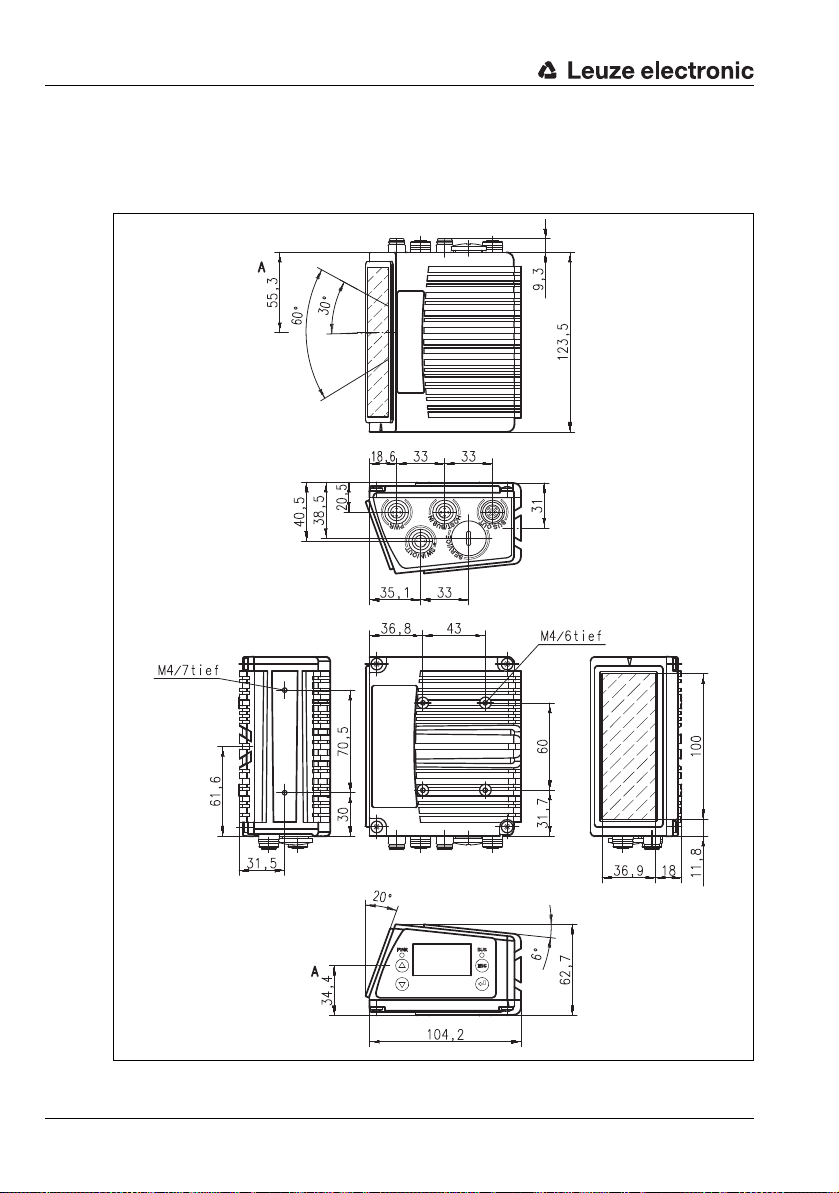
Specifications
A – Optical axis
5.3 Dimensioned drawings
5.3.1 Line scanner with / without heating
Figure 5.1: Dimensioned drawing BCL 548i line scanner S…102
44 BCL 548i Leuze electronic
Page 47
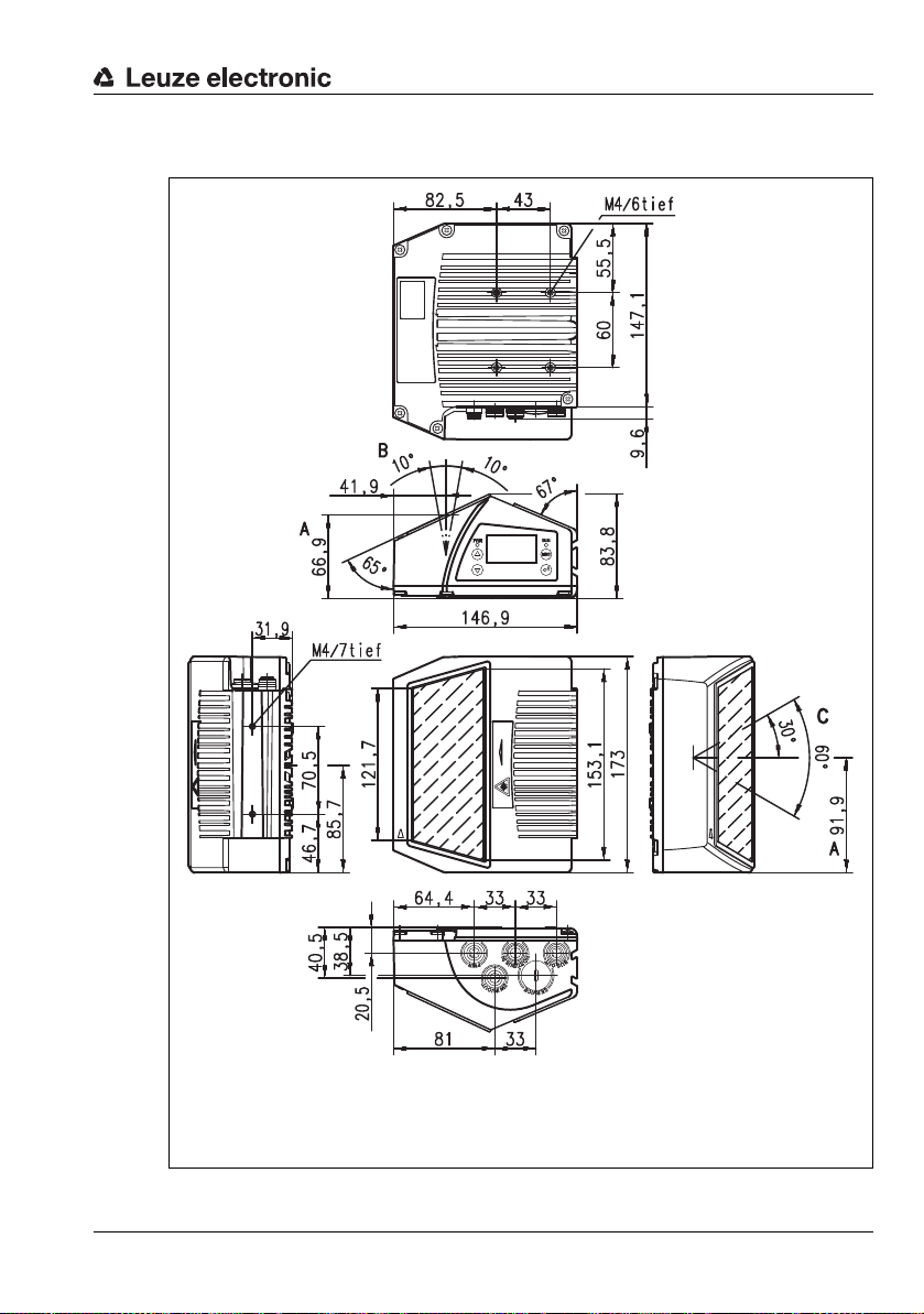
5.3.2 Deflection mirror scanner with / without heating
A – Optical axis
B – Optical adjustment range
C – Opening angle
The opening angle is reduced on devices with heating, see "Reading field curves for heating devices"
on page 58.
Specifications
Figure 5.2: Dimensioned drawing BCL 548i deflection-mirror scanner S…100
Leuze electronic BCL 548i 45
TNT 35/7-24V
Page 48

Specifications
A – Optical axis
B – Optical swivel range
C – Opening angle
The optical swivel range and the opening angle are reduced on devices with heating, see "Reading
field curves for heating devices" on page 58.
5.3.3 Oscillating-mirror scanner with / without heating
46 BCL 548i Leuze electronic
Figure 5.3: Dimensioned drawing BCL 548i oscillating-mirror scanner O…100
Page 49

5.4 Type overview BCL 548i
BCL 548i family
(PROFINET-IO on 2x M 12 D-coded)
Type designation Description Part no.
High Density Optics (m = 0.25 … 0.5mm)
BCL 548i SN 100 Line scanner with deflection mirror 50113185
BCL 548i SN 102 Line scanner, beam exit at the front 50113183
BCL 548i ON 100 Oscillating-mirror scanner 50113199
BCL 548i SN 100 H Line scanner with deflection mirror, with heating 50113186
BCL 548i SN 102 H Line scanner, beam exit at the front, with heating 50113184
BCL 548i ON 100 H Oscillating-mirror scanner with heating 50113200
Medium Density Optics (m = 0.35 … 1.0mm)
BCL 548i SM 100 Line scanner with deflection mirror 50113189
BCL 548i SM 102 Line scanner, beam exit at the front 50113187
BCL 548i OM 100 Oscillating-mirror scanner 50113201
BCL 548i SM 100 H Line scanner with deflection mirror, with heating 50113190
BCL 548i SM 102 H Line scanner, beam exit at the front, with heating 50113188
BCL 548i OM 100 H Oscillating-mirror scanner with heating 50113202
Low Density Optics (m = 0.5 … 1.0mm)
BCL 548i SF 100 Line scanner with deflection mirror 50113197
BCL 548i SF 102 Line scanner, beam exit at the front 50113195
BCL 548i OF 100 Oscillating-mirror scanner 50113205
BCL 548i SF 100 H Line scanner with deflection mirror, with heating 50113198
BCL 548i SF 102 H Line scanner, beam exit at the front, with heating 50113196
BCL 548i OF 100 H Oscillating-mirror scanner with heating 50113206
Specifications
Ultra Low Density Optics (m = 0.7 … 1.0mm)
BCL 548i SL 102 Line scanner, beam exit at the front 50113191
BCL 548i OL 100 Oscillating-mirror scanner 50113203
BCL 548i SL 102 H Line scanner, beam exit at the front, with heating 50113192
BCL 548i OL 100 H Oscillating-mirror scanner with heating 50113204
Table 5.7: Type overview BCL 548i
Leuze electronic BCL 548i 47
TNT 35/7-24V
Page 50

Specifications
M = Module: The narrowest line or space of a bar code in mm.
Z
B
= Wide element: Wide lines and spaces are a multiple (ratio) of the
module.
Module x Ratio = Z
B
(Normal Ratio 1 : 2.5).
B
Z
= Quiet zone: The quiet zone should be at least 10 times the
module, but not less than 2.5mm.
L = Code length: The length of the bar code in mm including the start
and stop characters. The quiet zone is included depending on the
code definition.
S
L
= Bar length: Height of the elements in mm.
5.5 Reading field curves / optical data
Bar code characteristics
Notice!
Please note that the size of the bar code module influences the maximum reading distance
and the width of the reading field. Therefore, when selecting a mounting location and/or the
bar code label, take into account the different reading characteristics of the scanner with
various bar code modules.
Figure 5.4: The most important characteristics of a bar code
The range in which the bar code can be read by the BCL 548i (the so-called reading field)
depends on the quality of the printed bar code and its dimensions.
Therefore, above all, the module of a bar code is decisive for the size of the reading field.
Notice!
A rule of thumb: The smaller the module of the bar code is, the smaller the maximum reading
distance and reading field width will be.
48 BCL 548i Leuze electronic
Page 51

5.6 Reading field curves
Zero position
Distance acc. to reading field curves
Notice!
Please notice that the real reading fields are also influenced by factors such as labeling
material, printing quality, scanning angle, printing contrast etc., and may thus deviate from
the reading fields specified here.
The zero position of the reading distance always refers the front edge of the housing of the
beam exit and is shown in figure 5.5 for the two housing types of the BCL 548i.
Specifications
Figure 5.5: Zero position of the reading distance
Reading conditions for the reading field curves
Bar code type 2/5 Interleaved
Ratio 1:2,5
Leuze electronic BCL 548i 49
ANSI specification class A
Reading rate > 75%
Table 5.8: Reading conditions
TNT 35/7-24V
Page 52

Specifications
Read distance [mm]
Reading field width [mm]
5.6.1 High Density (N) Optics: BCL 548i SN 100/102
400
300
200
100
-100
-200
-300
-400
0-100 200100 300 400 500 600 700 800 900 1000
BCL 500/501/504/508/548i SN 100/102
m = 0,3
m = 0,35
m = 0,25
m = 0,25
m = 0,3
m = 0,35
m = 0,5
m = 0,5
Figure 5.6: "High Density" reading field curve for line scanner (with/without deflection mirror)
The reading field curve applies for the reading conditions stated in table 5.8.
50 BCL 548i Leuze electronic
Page 53

5.6.2 High Density (N) Optics: BCL 548i ON 100
0-100 100 200 300 400 500 600 700 800 900 1000
100
200
300
400
-100
-200
-300
-400
BCL 500/501/504/508/548i ON 100
m = 0,25
m = 0,3
m = 0,35
m = 0,5
m = 0,35
m = 0,3
m = 0,25
m = 0,5
Read distance [mm]
Reading field width [mm]
Read distance [mm]
Reading field height [mm]
Figure 5.7: "High Density" reading field curve for oscillating-mirror scanners
Specifications
400
300
200
100
-100
-200
-300
-400
-100
0 100
200 300 400 500 600 700 800 900 1000
Figure 5.8: Lateral "High Density" reading field curve for oscillating-mirror scanners
The reading field curves apply for the reading conditions stated in table 5.8.
Leuze electronic BCL 548i 51
BCL 500/501/504/508/548i ON 100
m = 0,3
m = 0,5
m = 0,35
m = 0,25
m = 0,25
m = 0,3
m = 0,35
m = 0,5
TNT 35/7-24V
Page 54

Specifications
Read distance [mm]
Reading field width [mm]
5.6.3 Medium Density (M) Optics: BCL 548i SM 100/102
400
300
200
100
-100
-200
-300
-400
BCL 500/501/504/508/548i SM 100/102
m = 0,5
m = 0,35
100 200-100 0 300 400 500 600 700 800 900 1000 1100
m = 0,8 … 1,0
Figure 5.9: "Medium Density" reading field curve for line scanner (with/without deflection mirror)
The reading field curves apply for the reading conditions stated in table 5.8.
m = 0,35
m = 0,5
m = 0,8
…
m = 1,0
52 BCL 548i Leuze electronic
Page 55

5.6.4 Medium Density (M) Optics: BCL 548i OM 100
0-100 100 200 300 400 500 600 700 800 900 1000 1100
100
200
300
400
-100
-200
-300
-400
BCL 500/501/504/508/548i OM 100
m = 0,35
m = 0,5
m = 0,8
…
m = 1,0
m = 0,5
m = 0,35
m = 0,8 … 1,0
Read distance [mm]
Reading field width [mm]
0 100
-100
200 300 400 500 600 700 800 900 11001000
100
200
300
400
-100
-200
-300
-400
BCL 500/501/504/508/548i OM 100
m = 0,35
m = 0,5
m = 0,8
…
m = 1,0
m = 0,5
m = 0,35
m = 0,8 … 1,0
Read distance [mm]
Reading field height [mm]
Figure 5.10: "Medium Density" reading field curve for oscillating-mirror scanners
Specifications
Figure 5.11: Lateral "Medium Density" reading field curve for oscillating-mirror scanners
The reading field curves apply for the reading conditions stated in table 5.8.
Leuze electronic BCL 548i 53
TNT 35/7-24V
Page 56

Specifications
100 200-100 0 300 400 500 600 700 800 900 1000 1100 1200 1300 1400 1500 1600 1700
100
-100
-200
-300
-400
-500
-600
-700
200
300
400
500
600
700
BCL 500/501/504/508/548i SF 100/102
m = 1,0
m = 0,8
m = 0,5
m = 0,5
m = 0,8
m = 1,0
Read distance [mm]
Reading field width [mm]
5.6.5 Low Density (F) Optics: BCL 548i SF 100/102
Figure 5.12: "Low Density" reading field curve for line scanner (with/without deflection mirror)
The reading field curves apply for the reading conditions stated in table 5.8.
54 BCL 548i Leuze electronic
Page 57

5.6.6 Low Density (F) Optics: BCL 548i OF 100
Read distance [mm]
Reading field width [mm]
Read distance [mm]
Reading field height [mm]
Specifications
700
600
500
400
300
200
100
-100
-200
-300
-400
-500
-600
-700
0-100 100 200 300 400 500 600 700 800 900 1000 1100 1200 1300 1400 1500 17001600
BCL 500/501/504/508/548i OF 100
m = 0,5
m = 0,8
Figure 5.13: "Low Density" reading field curve for oscillating-mirror scanners
700
600
500
400
300
200
100
BCL 500/501/504/508/548i OF 100
m = 0,5
m = 0,8
m = 1,0
m = 1,0
m = 0,5
m = 0,8
m = 1,0
-100
-200
-300
-400
-500
-600
-700
-100
m = 0,5
0 100
200 300 400 500 600 700 800 900 1000 1100 1200 1300 1400 1500 17001600
m = 1,0
m = 0,8
Figure 5.14: Lateral "Low Density" reading field curve for oscillating-mirror scanners
The reading field curves apply for the reading conditions stated in table 5.8.
Leuze electronic BCL 548i 55
TNT 35/7-24V
Page 58

Specifications
Read distance [mm]
Reading field width [mm]
5.6.7 Ultra Low Density (L) Optics: BCL 548i SL 102
800
600
400
200
-200
-400
-600
-800
200 400 600 800 1000 1200 1400 1600 1800 2000 2200 2400 26000
BCL 500/501/504/508/548i SL 102
m = 0,7
m = 0,8
m = 1,0
Figure 5.15: "Ultra Low Density" reading field curve for line scanner without deflection mirror
The reading field curves apply for the reading conditions stated in table 5.8.
m = 0,7
m = 0,8
m = 1,0
56 BCL 548i Leuze electronic
Page 59

5.6.8 Ultra Low Density (L) Optics: BCL 548i OL 100
Read distance [mm]
Reading field width [mm]
200 400 600 800 1000 1200 1400 1600 1800 2000 2200 2400 26000
-200
-400
-600
-800
-1000
1000
200
400
600
800
BCL 500/501/504/508/548i OL 100
m = 0,7
m = 0,8
m = 1,0
m = 1,0
m = 0,8
m = 0,7
Read distance [mm]
Reading field height [mm]
Specifications
800
600
400
200
-200
-400
-600
-800
200 400 600 800 1000 1200 1400 1600 1800 2000 2200 2400 26000
BCL 500/501/504/508/548i OL 100
m = 0,7
m = 0,8
Figure 5.16: "Ultra Low Density" reading field curve for oscillating-mirror scanners
m = 0,7
m = 0,8
m = 1,0
m = 1,0
Figure 5.17: Lateral "Ultra Low Density" reading field curve for oscillating-mirror scanners
The reading field curves apply for the reading conditions stated in table 5.8.
Leuze electronic BCL 548i 57
TNT 35/7-24V
Page 60

Specifications
100 200-100 0 300 400 500 600 700 800 900 1000
100
200
300
400
-100
-200
-300
-400
BCL 500/501/504/508/548i SN 102 H
m = 0,25
m = 0,3
m = 0,35
m = 0,5
m = 0,35
m = 0,3
m = 0,25
m = 0,5
Read distance [mm]
Reading field width [mm]
5.7 Reading field curves for heating devices
The reading field curves of the heating devices differ to some extent from the normal reading
curves due to the optics heating and are somewhat reduced in the reading field width as
well as in the reading field height!
• The maximum opening angle for all oscillating and deflection mirror devices
(BCL 548i…100 H) is reduced to ±28° (without heating = ±30°).
• In addition, the maximum swivel range for all oscillating mirror devices
(BCL 548i O…100 H) is reduced to ±12° (without heating = ±20°). The deflection
mirror models (BCL 548i S…100 H) are not affected by this limitation.
• The reading field curves and opening angles are unchanged for all line scanners with
heating (BCL 548i S…102 H).
For details, please refer to the following reading field curves for the heating devices.
5.7.1 High Density (N) Optics: BCL 548i SN 102 H
58 BCL 548i Leuze electronic
Figure 5.18: "High Density" reading field curve for line scanner with heating (without deflection mirror)
The reading field curve applies for the reading conditions stated in table 5.8.
Page 61
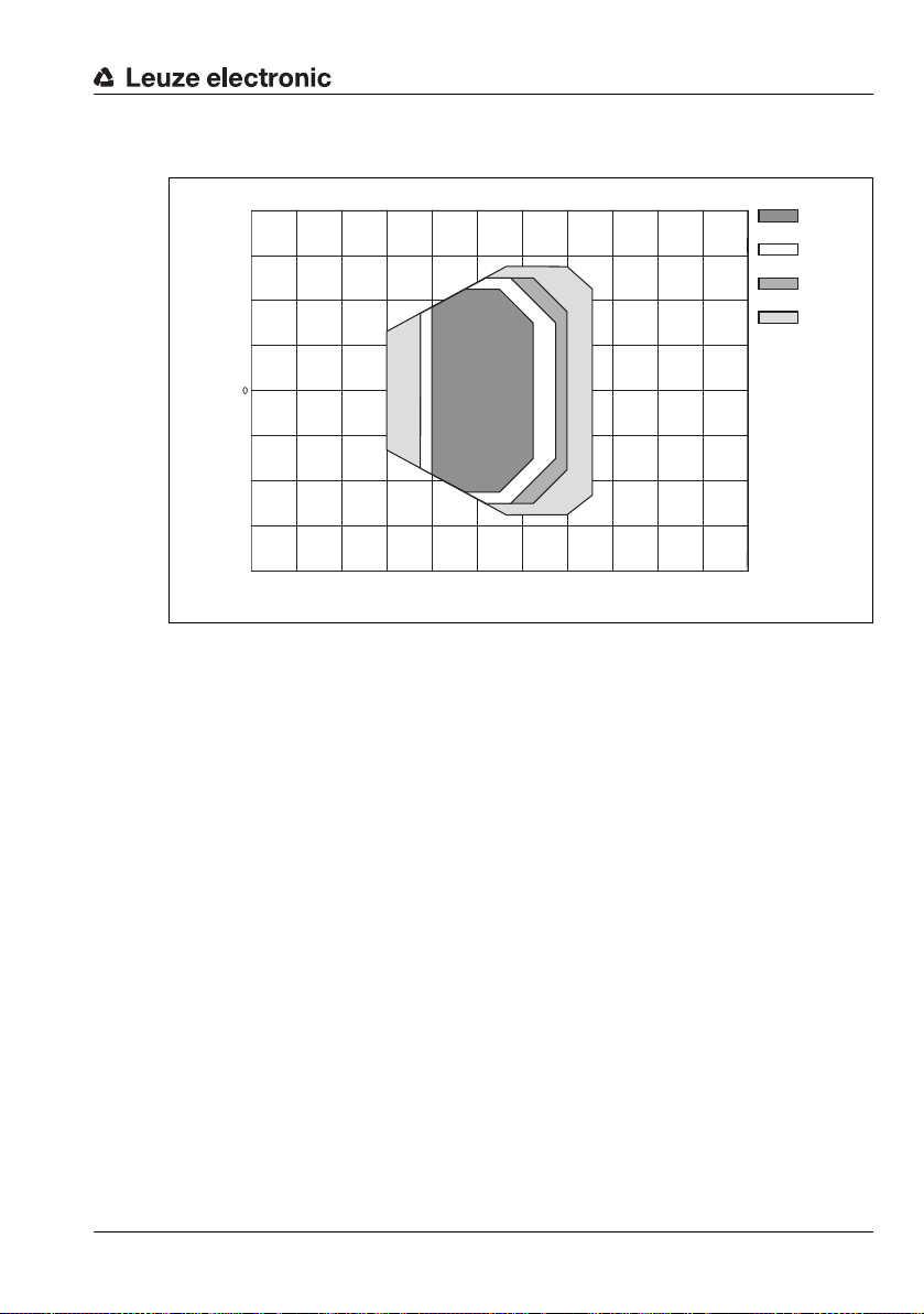
5.7.2 High Density (N) Optics: BCL 548i SN 100 H
100 200-100 0 300 400 500 600 700 800 900 1000
100
200
300
400
-100
-200
-300
-400
BCL 500/501/504/508/548i SN 100 H
m = 0,25
m = 0,3
m = 0,35
m = 0,5
m = 0,35
m = 0,3
m = 0,25
m = 0,5
Read distance [mm]
Reading field width [mm]
Figure 5.19: "High Density" reading field curve for line scanner with heating (with deflection mirror)
The reading field curve applies for the reading conditions stated in table 5.8.
Specifications
Leuze electronic BCL 548i 59
TNT 35/7-24V
Page 62
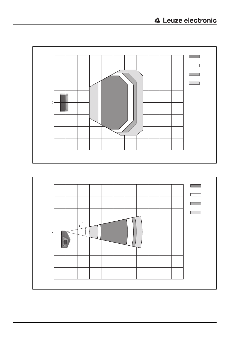
Specifications
Read distance [mm]
Reading field width [mm]
0 100
-100
200 300 400 500 600 700 800 900 1000
100
200
300
400
-100
-200
-300
-400
BCL 500/501/504/508/548i ON 100 H
m = 0,25
m = 0,3
m = 0,35
m = 0,5
m = 0,35
m = 0,3
m = 0,25
m = 0,5
= ±12˚
Read distance [mm]
Reading field height [mm]
5.7.3 High Density (N) Optics: BCL 548i ON 100 H
BCL 500/501/504/508/548i ON 100 H
m = 0,3
m = 0,5
m = 0,35
m = 0,25
-100
-200
-300
-400
400
300
200
100
1000-100 200 300 400 500 600 700 800 900 1000
Figure 5.20: "High Density" reading field curve for oscillating-mirror scanners with heating
m = 0,25
m = 0,3
m = 0,35
m = 0,5
Figure 5.21: Lateral "High Density" reading field curve for oscillating-mirror scanners with heating
60 BCL 548i Leuze electronic
The reading field curves apply for the reading conditions stated in table 5.8.
Page 63

5.7.4 Medium Density (M) Optics: BCL 548i SM 102 H
100 200-100 0 300 400 500 600 700 800 900 1000 1100
100
200
300
400
-100
-200
-300
-400
BCL 500/501/504/508/548i SM 102 H
m = 0,35
m = 0,5
m = 0,8
…
m = 1,0
m = 0,5
m = 0,35
m = 0,8 … 1,0
Read distance [mm]
Reading field width [mm]
Figure 5.22: "Medium Density" reading field curve for line scanner with heating (without deflection mirror)
The reading field curves apply for the reading conditions stated in table 5.8.
Specifications
Leuze electronic BCL 548i 61
TNT 35/7-24V
Page 64

Specifications
Read distance [mm]
Reading field width [mm]
5.7.5 Medium Density (M) Optics: BCL 548i SM 100 H
BCL 500/501/504/508/548i SM 100 H
m = 0,35
m = 0,5
m = 0,8
…
m = 1,0
m = 0,5
m = 0,35
m = 0,8 … 1,0
-100
-200
-300
-400
400
300
200
100
100 200-100 0 300 400 500 600 700 800 900 1000 1100
Figure 5.23: "Medium Density" reading field curve for line scanner with heating (with deflection mirror)
The reading field curves apply for the reading conditions stated in table 5.8.
62 BCL 548i Leuze electronic
Page 65

5.7.6 Medium Density (M) Optics: BCL 548i OM 100 H
1000-100 200 300 400 500 600 700 800 900 1000 1100
100
200
300
400
-100
-200
-300
-400
BCL 500/501/504/508/548i OM 100 H
m = 0,35
m = 0,5
m = 0,8
…
m = 1,0
m = 0,5
m = 0,35
m = 0,8 … 1,0
Read distance [mm]
Reading field width [mm]
0 100
-100
200 300 400 500 600 700 800 900 11001000
100
200
300
400
-100
-200
-300
-400
BCL 500/501/504/508/548i OM 100 H
m = 0,35
m = 0,5
m = 0,8
…
m = 1,0
m = 0,5
m = 0,35
m = 0,8 … 1,0
= ±12˚
Read distance [mm]
Reading field height [mm]
Figure 5.24: "Medium Density" reading field curve for oscillating-mirror scanners with heating
Specifications
Figure 5.25: Lateral "Medium Density" reading field curve for oscillating-mirror scanners with heating
The reading field curves apply for the reading conditions stated in table 5.8.
Leuze electronic BCL 548i 63
TNT 35/7-24V
Page 66

Specifications
100 200-100 0 300 400 500 600 700 800 900 1000 1100 1200 1300 1400 1500 1600 1700
100
-100
-200
-300
-400
-500
-600
-700
200
300
400
500
600
700
BCL 500/501/504/508/548i SF 102 H
m = 1,0
m = 0,8
m = 0,5
m = 0,5
m = 0,8
m = 1,0
Read distance [mm]
Reading field width [mm]
5.7.7 Low Density (F) Optics: BCL 548i SF 102 H
Figure 5.26: "Low Density" reading field curve for line scanner with heating (without deflection mirror)
The reading field curves apply for the reading conditions stated in table 5.8.
64 BCL 548i Leuze electronic
Page 67

5.7.8 Low Density (F) Optics: BCL 548i SF 100 H
Read distance [mm]
Reading field width [mm]
Specifications
700
600
500
400
300
200
100
-100
-200
-300
-400
-500
-600
-700
100 200-100 0 300 400 500 600 700 800 900 1000 1100 1200 1300 1400 1500 1600 1700
BCL 500/501/504/508/548i SF 100 H
m = 0,5
m = 0,8
m = 0,5
m = 0,8
m = 1,0
m = 1,0
Figure 5.27: "Low Density" reading field curve for line scanner with heating (with deflection mirror)
The reading field curves apply for the reading conditions stated in table 5.8.
Leuze electronic BCL 548i 65
TNT 35/7-24V
Page 68

Specifications
1000-100 200 300 400 500 600 700 800 900 1000 1100 1200 1300 1400 1500 1600 1700
100
-100
-200
-300
-400
-500
-600
-700
200
300
400
500
600
700
BCL 500/501/504/508/548i OF 100 H
m = 1,0
m = 0,8
m = 0,5
m = 0,5
m = 0,8
m = 1,0
Read distance [mm]
Reading field width [mm]
Read distance [mm]
Reading field height [mm]
5.7.9 Low Density (F) Optics: BCL 548i OF 100 H
Figure 5.28: "Low Density" reading field curve for oscillating-mirror scanners with heating
700
600
500
400
300
200
100
-100
-200
-300
-400
-500
-600
-700
0 100
-100
Figure 5.29: Lateral "Low Density" reading field curve for oscillating-mirror scanners with heating
The reading field curves apply for the reading conditions stated in table 5.8.
66 BCL 548i Leuze electronic
BCL 500/501/504/508/548i OF 100 H
= ±12˚
m = 0,8
m = 0,5
200 300 400 500 600 700 800 900 1000 1100 1200 1300 1400 1500 17001600
m = 0,5
m = 0,8
m = 1,0
m = 1,0
Page 69

5.7.10 Ultra Low Density (L) Optics: BCL 548i SL 102 H
Read distance [mm]
Reading field width [mm]
Specifications
800
600
400
200
-200
-400
-600
-800
200 400 600 800 1000 1200 1400 1600 1800 2000 2200 2400 26000
BCL 500/501/504/508/548i SL 102 H
m = 0,7
m = 0,8
m = 0,7
m = 0,8
m = 1,0
m = 1,0
Figure 5.30: "Ultra Low Density" reading field curve for line scanner with heating (without deflection mirror)
The reading field curves apply for the reading conditions stated in table 5.8.
Leuze electronic BCL 548i 67
TNT 35/7-24V
Page 70

Specifications
Read distance [mm]
Reading field width [mm]
200 400 600 800 1000 1200 1400 1600 1800 2000 2200 2400 26000
-200
-400
-600
-800
-1000
1000
200
400
600
800
BCL 500/501/504/508/548i OL 100 H
m = 0,7
m = 0,8
m = 1,0
±12˚
m = 1,0
m = 0,8
m = 0,7
Read distance [mm]
Reading field height [mm]
5.7.11 Ultra Low Density (L) Optics: BCL 548i OL 100 H
800
600
400
200
-200
-400
-600
-800
200 400 600 800 1000 1200 1400 1600 1800 2000 2200 2400 26000
BCL 500/501/504/508/548i OL 100 H
m = 0,7
m = 0,8
m = 0,7
m = 0,8
m = 1,0
m = 1,0
Figure 5.31: "Ultra Low Density" reading field curve for oscillating-mirror scanners with heating
68 BCL 548i Leuze electronic
Figure 5.32: Lateral "Ultra Low Density" reading field curve for oscillating-mirror scanners with heating
The reading field curves apply for the reading conditions stated in table 5.8.
Page 71

6 Installation and mounting
6.1 Storage, transportation
Attention!
When transporting or storing, package the device s o th at it i s pr otected against collision and
humidity. Optimum protection is achieved when using the original packaging. Heed the
required environmental conditions specified in the technical data.
Unpacking
Check the packaging for any damage. If damage is found, notify the post office or shipping
agent as well as the supplier.
Check the delivery contents using your order and the delivery papers:
• Delivered quantity
• Device type and model as indicated on the nameplate
• Laser warning signs
• Brief manual
The name plate provides information as to what BCL type your device is. For specific information, please refer to chapter 5.
Name plates of the bar code readers of the BCL 500i series
Installation and mounting
Figure 6.1: Device name plate BCL 548i
Save the original packaging for later storage or shipping.
If you have any questions concerning your shipment, please contact your supplier or your
local Leuze electronic sales office.
Observe the applicable local regulations when disposing of the packaging materials.
Leuze electronic BCL 548i 69
TNT 35/7-24V
Page 72

Installation and mounting
6.2 Mounting the BCL 548i
The BCL 548i bar code readers can be mounted in two different ways:
• Using two M4x6 screws on the rear of the device or using four M4x6 screws on the
bottom of the device.
• Using a BT 56 mounting device on the two fastening grooves.
6.2.1 Fastening with M4 x 6 screws
Figure 6.2: Fastening options using M4x6 threaded holes
70 BCL 548i Leuze electronic
Page 73

6.2.2 BT 56 mounting device
Clamping jaws for
mounting on the
BCL 548i
Clamp profile for
mounting to round or
oval pipes
Ø16…20mm
A Rod holder, turnable 360°
B Rods Ø 16 … 20mm
All dimensions in mm
The BT 56 mounting device is available for mounting the BCL 548i using the fastening
grooves. It is designed for rod installation (Ø 16mm to 20mm). For ordering instructions,
please refer to chapter "Type overview and accessories" on page 227.
BT 56 mounting device
Installation and mounting
Figure 6.3: BT 56 mounting device
Leuze electronic BCL 548i 71
TNT 35/7-24V
Page 74

Installation and mounting
Figure 6.4: Mounting example of BCL 548i with BT 56
72 BCL 548i Leuze electronic
Page 75

6.2.3 BT 59 mounting device
Clamping jaws for mounting
on the BCL 548i
A Holder, turnable 360°
B ITEM joint, angle adjustable ±90°
C M 8x16 screw cylinder, M 8 wave washer, M 8
sliding block, connectors for ITEM profile (2x)
alle Maße in mm
The BT 59 mounting device offers you an additional fastening option. For ordering instructions, please refer to chapter "Type overview and accessories" on page 227.
BT 59 mounting device
Installation and mounting
Leuze electronic BCL 548i 73
BT 59 mounting device
Notice!
When mounting, ensure that the scanning beam is not reflected directly back to the scanner
by the label which is being read. For further information, see the notices in chapter 6.3!
Please refer to chapter 5.6 for the permissible minimum and maximum distances between
the BCL 548i and the labels to be read.
TNT 35/7-24V
Page 76

Installation and mounting
6.3 Device arrangement
6.3.1 Selecting a mounting location
In order to select the right mounting location, several factors must be considered:
• Size, orientation, and position tolerance of the bar codes on the objects to be scanned.
• The reading field of the BCL 548i in relation to the bar code module width.
• The resulting minimum and maximum reading distance from the respective reading
field (see chapter 5.5 "Reading field curves / optical data").
• The permissible cable lengths between the BCL 548i and the host system depending
on which interface is used.
• The correct time for data output. The BCL 548i should be positioned in such a way
that, taking into consideration the time required for data processing and the conveyor
belt speed, there is sufficient time to e.g. initiate sorting operations on the basis of the
read data.
• The display and control panel should be very visible and accessible.
• For configuring and commissioning with the webConfig tool, the USB interface should
be easily accessible.
For specific information, please refer to chapter 4.4.
Notice!
The beam exits the BCL 548i as follows for the respective devices:
- line scanner parallel to the housing base
- oscillating mirror and deflection mirror perpendicular to the housing base
The black areas in figure 6.1 are the housing base. The best read results are obtained when:
• The BCL 548i is mounted in such a way that the scanning beam is incident on the bar
code at an angle of inclination greater than ±10° … 15° to vertical.
• The reading distance lies in the middle area of the reading field.
• The bar code labels are of good print quality and have good contrast ratios.
• You do not use high-gloss labels.
• There is no direct sunlight.
74 BCL 548i Leuze electronic
Page 77

Installation and mounting
Z
e
r
o
p
o
s
i
t
i
o
n
D
i
s
t
a
n
c
e
a
c
c
.
t
o
r
e
a
d
i
n
g
f
i
e
l
d
c
u
r
v
e
s
Bar code
The BCL 548i should be mounted in such a way that the
scanning beam is incident on the bar code at an angle of
inclination greater than ±10° … 15° to vertical.
±
1
0
…
1
5
°
6.3.2 Avoiding total reflection – Line scanner
The bar code label must be positioned at an angle of inclination greater than ±10° … 15°
from vertical in order to avoid total reflection of the laser beam (see figure 6.5)!
Total reflection occurs whenever the laser light of the bar code reader is directly incident
on the surface of the bar code at an angle of 90°. The light directly reflected by the bar code
may overload the bar code reader and thereby cause non-readings!
Figure 6.5: Total reflection – line scanner
6.3.3 Avoiding total reflection – oscillating/deflection-mirror scanner
For the BCL 548i with oscillating/deflection mirror, the laser beam exits at an angle of 90°
to vertical.
For the BCL 548i with deflection mirror, it is also possible to use software to adjust the
direction of the beam by ±10°.
For the BCL 548i with oscillating mirror, the swivel range of ±20° (±12° for devices with
heating) is to be taken into account.
This means that in order to be on the safe side and to avoid total reflection, the BCL 548i
with oscillating/deflection mirror must be inclined upward or downward 20° … 30°!
Notice!
Mount the BCL 548i with oscillating/deflection mirror in such a way that the outlet window
of the bar code reader is parallel to the object. This will result in an angle of inclination of
approx. 25°.
TNT 35/7-24V
Leuze electronic BCL 548i 75
Page 78

Installation and mounting
Z
e
r
o
p
o
s
i
t
i
o
n
D
i
s
t
a
n
c
e
a
c
c
.
t
o
r
e
a
d
i
n
g
f
i
e
l
d
c
u
r
v
e
s
Bar code
±
2
5
°
The BCL 548i should be mounted in such a way that the scanning
beam is incident on the bar code at an angle of inclinatio n greater
than ±25° to vertical.
Figure 6.6: Total reflection – BCL 548i with oscillating/deflection mirror
6.3.4 Mounting location
When selecting a mounting location, pay attention to:
• Maintaining the required environmental conditions (temperature, humidity).
• Possible soiling of the reading window due to liquids, abrasion by boxes, or packaging
material residues.
• Lowest possible chance of damage to the BCL 548i by mechanical collision or jammed
parts.
• Possible extraneous light (no direct sunlight or sunlight reflected by the bar code).
6.3.5 Devices with integrated heating
For devices with integrated heating, also observe the following points:
• Mount the BCL 548i in a way which provides maximum thermal isolation, e.g. using
rubber-bonded metal.
• Mount in such a way that the device is protected from draft and wind; mount additional
shields if necessary.
Notice!
When installing the BCL 548i in a protective housing, it must be ensured that the scanning
beam can exit the protective housing without obstruction.
76 BCL 548i Leuze electronic
Page 79

Installation and mounting
6.3.6 Possible read angles between BCL 548i and bar code
The optimum alignment of the BCL 548i is accomplished when the scan line scans the code
bars almost at a right angle (90°). All read angles that are possible between the scan line
and bar code must be taken account (figure 6.7).
Figure 6.7: Reading angle for the line scanner
Tilt
Angle of inclination (Pitch)
Skew
In order to avoid total reflection, the skew should be greater than 10°
6.4 Attaching laser warning sign
Attention Laser!
Follow the safety notices in chapter 2.
It is important that you attach the sticky labels supplied to the device (laser warning signs
and laser emission symbol)! If the signs would be covered due to the installation situation
of the BCL 548i, attach them instead in the immediate vicinity of the BCL 548i in such a
way that it is not necessary to look into the laser beam when reading the notices!
6.5 Cleaning
Clean the glass window of the BCL 548i with a soft cloth after mounting. Remove all pack-
aging remains, e.g. carton fibers or Styrofoam balls. In doing so, avoid leaving fingerprints
on the front cover of the BCL 548i.
Attention!
Do not use aggressive cleaning agents such as thinner or acetone for cleaning the device.
Leuze electronic BCL 548i 77
TNT 35/7-24V
Page 80

Electrical connection
7 Electrical connection
The BCL 548i bar code readers are connected using variously coded M12 connectors. This
ensures unique connection assignments.
The additional USB interface is used for configuring the device.
For the locations of the individual device connections, please refer to the device detail shown
below.
Notice!
The corresponding mating connectors and ready-made cables are available as accessories
for all cables. For additional information, refer to chapter chapter 13.
Figure 7.1: Location of the electrical connections
7.1 Safety notices for the electrical connection
Attention!
Do not open the device yourself under any circumstances! There is otherwise a risk of uncontrolled emission of laser radiation from the device. The housing of the BCL 548i contains no
parts that need to be adjusted or maintained by the user.
Before connecting the device, be sure that the supply voltage agrees with the value printed
on the name plate.
Connection of the device and cleaning must only be carried out by a qualified electrician.
Ensure that the functional earth (FE) is connected correctly. Unimpaired operation is only
guaranteed when the functional earth is connected properly.
If faults cannot be corrected, the device should be removed from operation and protected
against possible use.
Attention!
For UL applications, use is permitted exclusively in Class 2 circuits according to NEC
(National Electric Code).
The BCL 548i bar code readers are designed in accordance with safety class III for supply
by PELV (protective extra-low voltage with reliable disconnection).
78 BCL 548i Leuze electronic
Page 81

Notice!
USB socket
Type A
M12 socket
(A-coded)
M12 socket
(D-coded)
M12 socket
(D-coded)
M12 plug
(A-coded)
Protection class IP65 is achieved only if the connectors and caps are screwed into place!
7.2 Electrical connection of the BCL 548i
As a PROFINET-IO participant, the BCL 548i is equipped with four M 12 plugs / sockets
which are A- and D-coded.
The voltage supply (PWR) as well as the four freely configurable switching inputs/outputs
(SW IN/OUT and PWR) are connected there.
"HOST / BUS IN" is available as a PROFINET-IO interface for connecting to the host
system.
By means of the implemented switch function in the BCL 548i, an additional second
"BUS OUT" PROFINET-IO interface is available for creating a scanner network (linear
topology).
A USB connection serves as a "SERVICE" interface.
Electrical connection
SERVICE
GND D+ D-
U
B
2134
BUS OUT
RD+
2
TD+
1
Figure 7.2: Connections of the BCL 548i
Described in detail in the following are the individual connections and pin assignments.
RD-
4
TD-
3
HOST / BUS IN
TD+
1
RD+
RD-
2
4
VOUT
3
TD-
SW IN/OUT
SWIO_1
2
1
3
5
4
SWIO_2
GND VIN
GND
FE
PWR
SWIO_3
2
3
1
5
4
FE
SWIO_4
TNT 35/7-24V
Leuze electronic BCL 548i 79
Page 82

Electrical connection
PWR
SWIO_4
SWIO_3
3
2
1
4
5
GND VIN
FE
M12 plug
(A-coded)
7.2.1 PWR – Voltage supply and switching input/outputs 3 and 4
PWR (5-pin plug, A-coded)
Pin Name Remark
1 VIN Positive supply voltage +10 … +30 V DC
2 SWIO_3 Configurable switching input / output 3
3 GND Negative supply voltage 0VDC
4 SWIO_4 Configurable switching input / output 4
5 FE Functional earth
Thread FE Functional earth (housing)
Table 7.1: Pin assignment PWR
Supply voltage
Attention!
For UL applications, use is permitted exclusively in Class 2 circuits according to NEC
(National Electric Code).
The BCL 548i bar code readers are designed in accordance with safety class III for supply
by PELV (protective extra-low voltage with reliable disconnection).
Connecting functional earth FE
Ensure that the functional earth (FE) is connected correctly. Unimpaired operation is only
guaranteed when the functional earth is connected properly. All electrical disturbances
(EMC couplings) are discharged via the functional earth connection.
Switching input / output
The BCL 548i is equipped with four freely programmable, opto-decoupled switching inputs
and outputs SWIO_1 … SWIO_4.
The switching inputs can be used to activate various internal functions of the BCL 548i
(decoding, autoConfig, …). The switching outputs can be used to signal the state of the
BCL 548i and to implement external functions independent of the superior control.
The two switching inputs/outputs SWIO_1 and SWIO_2 are located on the SW IN/OUT M12
socket and are described in chapter 7.2.3. The other two (SWIO_3 and SWIO_4) of the four
freely configurable switching inputs/outputs are located on the PWR M12 connector.
Notice!
In general, configuration of the bar code reader takes place on the PROFINET-IO via the corresponding GSD file. Alternatively, you can temporarily set the respective function as input
or output via the display or with the aid of the webConfig configuration tool for the purpose
of testing the respective functionality. After reconnecting to the PROFINET-IO or after deactivating parameter enabling, the parameter settings set by the PROFINET-IO are again active!
80 BCL 548i Leuze electronic
Page 83

Electrical connection
Switching input
Switching output
from controller
(deactivated)
Switching input
to controller
Switching output
Switching output
from controller
Switching input
to controller
(deactivated)
Described in the following is the external wiring for use as a switching input or output; the
respective function assignments to the switching inputs/outputs can be found in chapter 10.
Function as switching input
Figure 7.3: Switching input connection diagram SWIO_3 and SWIO_4
If you use a sensor with a standard M12 connector, please note the following:
• Pins 2 and 4 must not be operated as switching outputs if sensors which function as
inputs are also connected to these pins.
If, for example, the inverted sensor output is connected to pin 2, and pin 2 of the bar code
reader is, at the same time, configured as an output (and not as an input), the switching
output malfunctions.
Attention!
The maximum input current must not exceed 8mA!
Function as switching output
Figure 7.4: Switching output connection diagram SWIO_3 / SWIO_4
Attention!
Each configured switching output is short-circuit proof! Do not load the respective switching
output of the BCL 548i with more than 60mA at +10 … +30VDC in normal operation!
Leuze electronic BCL 548i 81
TNT 35/7-24V
Page 84

Electrical connection
SERVICE
2134
GND D+ D-
U
B
Notice!
Both switching inputs/outputs SWIO_3 and SWIO_4 are configured by default in such a way
that:
• Switching input SWIO_3 activates the reading gate
• Switching output SWIO_4 switches on "No Read"
7.2.2 SERVICE – USB interface (type A)
SERVICE – USB interface (type A )
Pin Name Remark
1 VB Positive supply voltage +5V DC
2D-Data -
3D+Data +
4GNDGround
Figure 7.5: Pin assignments of SERVICE – USB interface
Attention!
Maximum load of the +5V DC supply voltage of the USB interface is 200mA!
Ensure adequate shielding.
The entire connection cable must absolutely be shielded acc. to the USB specifications.
Cable length must not exceed 3m.
Use the Leuze-specific USB service cable (see chapter 13 "Type overview and acces-
sories") for the connection and use a service PC to configure.
Notice!
IP 65 is achieved only if the connectors and caps are screwed into place. Alternatively, a
parameter memory in the form of a USB memory stick certified by Leuze electronic GmbH
+ Co. can be connected to the provided USB service interface. With this Leuze memory stick,
protection class IP 65 is also ensured.
82 BCL 548i Leuze electronic
Page 85

7.2.3 SW IN/OUT – Switching input/switching output
SW IN/OUT
VOUT
1
2
3
4
SWIO_1
SWIO_2
GND
FE
5
M12 socket
(A-coded)
Diffuse reflection
light scanner
Switching output
from controller
(deactivated)
Switching input
to controller
Output
SW IN/OUT (5-pin socket, A-coded)
Pin Name Remark
1VOUT
Voltage supply for sensors
(VOUT identical to VIN at PWR IN)
2SWIO_1Configurable switching input / output 1
3GNDGND for the sensors
4SWIO_2Configurable switching input / output 2
5FEFunctional earth
Thread FE Functional earth (housing)
Figure 7.6: Pin assignment SW IN/OUT
The BCL 548i is equipped with four freely programmable, opto-decoupled switching inputs
and outputs SWIO_1 … SWIO_4.
The two switching inputs/outputs SWIO_1 and SWIO_2 are located on the SW IN/OUT M12
socket. The other two (SWIO_3 and SWIO_4) of the four freely configurable switching inputs/
outputs are located on the PWR M 12 connector and are described in chapter 7.2.1.
Described in the following is the external wiring for use as a switching input or output; the
respective function assignments to the switching inputs/outputs can be found in chapter 10.
Function as switching input
Electrical connection
Figure 7.7: Switching input connection diagram SWIO_1 and SWIO_2
If you use a sensor with a standard M12 connector, please note the following:
• Pins 2 and 4 must not be operated as switching outputs if sensors which function as
inputs are also connected to these pins.
If, for example, the inverted sensor output is connected to pin 2, and pin 2 of the bar code
reader is, at the same time, configured as an output (and not as an input), the switching
output malfunctions.
Attention!
The maximum input current must not exceed 8mA!
Leuze electronic BCL 548i 83
TNT 35/7-24V
Page 86

Electrical connection
Switching output
Switching output
from controller
Switching input to
controller (deactivated)
Function as switching output
Figure 7.8: Switching output connection diagram SWIO_1 / SWIO_2
Attention!
Each configured switching output is short-circuit proof! Do not load the respective switching
output of the BCL 548i with more than 60mA at +10 … +30VDC in normal operation!
Notice!
Both switching inputs/outputs SWIO_1 and SWIO_2 are configured by default in such a way
that they function as switching inputs:
• Switching input SWIO_1 activates the start reading gate function
• Switching input SWIO_2 activates the reference code teach-in function
The functions of the individual switching inputs/outputs are programmed via the display or
via configuration in the webConfig tool under the Switching input or Switching output
heading.
For further information, see also "Commissioning and configuration" on page 116.
84 BCL 548i Leuze electronic
Page 87

7.2.4 HOST / BUS IN for BCL 548i
HOST / BUS IN
TD+
1
2
3
4
RD+
RD-
TD-
M12 socket
(D-coded)
TD+
1
2
3
4
RD+
RD-
TD-
BCL548 HOST / BUS IN RJ 45
TD+ (1)
TD- (2)
RD+ (3)
RD- (6)
1
8
Twisted pair
Twisted pair
The BCL 548i makes either the PROFINET-IO interface available as host interface.
HOST / BUS IN (4-pin socket, D-coded)
Thread FE Functional earth (housing)
Table 7.2: Pin assignment HOST / BUS IN BCL 548i
For the host connection of the BCL 548i, the "KB ET - … - SA-RJ45" ready-made cables
are preferred, see table 13.8 "Bus connection cable for the BCL 548i" on page 232.
PROFINET-IO cable assignments
Electrical connection
Pin Name Remark
1TD+ Transmit Data +
2RD+ Receive Data +
3TD- Transmit Data -
4RD- Receive Data -
Figure 7.9: HOST / BUS IN cable assignments on RJ-45
Notice for connecting the PROFINET-IO interface!
Ensure adequate shielding. The entire connection cable must be shielded and earthed. The
RD+/RD- and TD+/TD- wires must be stranded in pairs.
Use CAT 5 cable for the connection.
Leuze electronic BCL 548i 85
TNT 35/7-24V
Page 88

Electrical connection
BUS OUT
TD+
1
2
3
4
RD+
RD-
TD-
M12 socket
(D-coded)
7.2.5 BUS OUT for the BCL 548i
To set up a PROFINET-IO network with other participants with linear topology, the BCL 548i
makes available another PROFINET-IO RT interface. The use of this interface drastically
reduces the cabling requirements, as only the first BCL 548i requires a direct connection
to the switch, via which it can communicate with the host. All other BCL 548i are connected
in series to the first BCL 548i, see figure 7.11.
Table 7.3: Pin assignment BUS OUT
For the connection of two BCL 548i, the "KB ET - … - SSA" ready-made cables are pre-
ferred, see table 13.8 "Bus connection cable for the BCL 548i" on page 232.
If you use user-configurable cables, note the following:
Notice!
Ensure adequate shielding. The entire connection cable must be shielded and earthed. The
signal lines must be stranded in pairs.
Use CAT 5 cable for the connection.
BUS OUT (4-pin socket, D-coded)
Pin Name Remark
1TD+ Transmit Data +
2RD+ Receive Data +
3TD- Tr a nsmit Data -
4RD- Receive Data -
Thread FE Functional earth (housing)
Note!
For the BCL 548i as standalone device or as the last participant in a linear topology, termination on the BUS OUT socket is not mandatory!
86 BCL 548i Leuze electronic
Page 89

7.3 PROFINET-IO topologies
PC / PLC host interface
Other network participants
BCL 548i
myBCL 548i_1
PC / PLC host interface
to other network participants
BCL 548i
myBCL 548i_2
(device name 2)
BCL 548i
myBCL 548i_3
(device name 3)
I/O
PWR
I/O
PWR
I/O
PWR
BCL 548i
myBCL 548i_1
(device name 1)
The BCL 548i can be operated as a single device (standalone) with individual device name
in a PROFINET-IO star topology. The PLC must communicate this device name to the
participant during the "device naming" (see section "Step 5 – Configuration of the device
name - naming the device" on page 121).
Figure 7.10: PROFINET-IO in a star topology
The innovative further development of the BCL 548i with integrated switch functionality
offers the option of networking multiple bar code readers of type BCL 548i with one another.
In addition to the classic "star topology", a "linear topology" is thus also possible.
This makes wiring the network easy and inexpensive as participants are connected to one
another in parallel.
The maximum length of a segment (connection from one participant to the next) is limited
to 100m.
Electrical connection
Leuze electronic BCL 548i 87
Figure 7.11: PROFINET-IO in a line topology
Up to 254 bar code readers can be networked. They must all be located in the same subnet.
To do this, the individual "device name" is assigned to each participating BCL 548i through
"device naming", using the control's configuration tool. Detailed information can be found
in section "Step 5 – Configuration of the device name - naming the device" on page 121.
Information on the necessary configuration steps can be found in chapter 10.
TNT 35/7-24V
Page 90

Electrical connection
7.3.1 PROFINET-IO wiring
A Cat. 5 Ethernet cable should be used for wiring.
For the connection technology transition from M12 to RJ45, a "KDS ET M12 /
RJ 45 W - 4P" adapter is available that lets you connect standard network cables.
If no standard network cables are to be used (e.g. due to lacking IP… protection class), you
can use the "KB ET - … - SA" user-configurable cable on the BCL 548i, see table 13.8 "Bus
connection cable for the BCL 548i" on page 232.
The individual BCL 548i devices in a linear topology are connected with the "KB ET - … -
SSA" cable, see table 13.8 "Bus connection cable for the BCL 548i" on page 232.
For unavailable cable lengths, you can configure your cables yourself. When doing so, make
certain that you connect TD+ on the M 12 connector with RD+ on the RJ-45 connector and
TD- on the M12 connector with RD- on the RJ-45 connector, respectively, etc.
Notice!
Use the recommended connectors / sockets or the ready-made cables (see chapter 13
"Type overview and accessories").
7.4 Cable lengths and shielding
Observe the following maximum cable lengths and shielding types:
Connection Interface Max. cable length Shielding
BCL – service
BCL – host
Network from the
first BCL to the last
BCL
BCL – power supply
unit
Switching input
Switching output
Table 7.4: Cable lengths and shielding
USB 3 m
PROFINET-IO RT 100 m absolutely required, shielded
PROFINET-IO RT
the maximum segment length
must not exceed 100m for
100Base-TX Twisted Pair
(min.Cat.5)
30m not necessary
10m not necessary
10m not necessary
shielding absolutely
necessary acc. to USB
specifications
absolutely required, shielded
88 BCL 548i Leuze electronic
Page 91

8 Display and control panel
IO1 IO2 IO3
IO4 ATT ERR
LNK0
USB
MS
12345678
LNK1
LED
LED
Control buttons
Read result
Bar graph
Status display Link states
USB interface
8.1 Structure of the control panel
Figure 8.1: Structure of the control panel
Display and control panel
8.2 Status display and operation
8.2.1 Indicators in the display
Status displays of the switching inputs/outputs
IO1 Switching input or switching output 1 active (function dependent on set configuration).
Default: Switching input with the "Reading gate activation" function
IO2 Switching input or switching output 2 active (function dependent on set configuration).
Default: Input with the "Teach-in" function
IO3 Switching input or switching output 3 active (function dependent on set configuration).
Default: Switching input with the "Reading gate activation" function
IO4 Switching input or switching output 4 active (function dependent on set configuration).
ATT Warning (Attention)
ERR Internal device error (Error) -> The device must be sent in for inspection
Bar graph
The read quality is described on a scale of 0 - 100%. The quality is evaluated based on the
"Equal Scans" of the read result configured in the bar code reader.
Default: Switching output with the "No read" function
Leuze electronic BCL 548i 89
TNT 35/7-24V
Page 92

Display and control panel
Status display of the USB interface
USB The BCL 548i is connected to a PC via the USB interface.
MS An external parameter memory is properly connected to the USB interface of the
BCL 548i.
Read result
The read bar code information is displayed.
Link states
Displays the link states (LNK0 and LNK1) of the PROFINET-IO interface.
• LNK0: physical connection to the HOST / BUS IN port
• LNK1: physical connection to the BUS OUT port
8.2.2 LED status indicators
PWR LED
off Device OFF
flashes green Device ok, initialization phase
- no supply voltage
- no bar code reading possible
- voltage connected
- self test running
- initialization running
green continuous light Device ok
- bar code reading possible
- self test successfully finished
- device monitoring active
orange continuous light Service mode
- bar code reading possible
- configuration via the USB service interface
- configuration via the display
- no data on the host interface
flashes red Device ok, warning set
- bar code reading possible
- temporary operating fault
red continuous light Device error / parameter enable
- no bar code reading possible
90 BCL 548i Leuze electronic
Page 93

BUS LED
ESC
off No supply voltage
- no communication possible
- PROFINET-IO communication not initialized or inactive
flashes green Initialization
- of the BCL 548i, establishing communication
green continuous light Operation ok
- Network operation ok
- Connection and communication to IO Controller (PLC)
established ("data exchange")
flashes red Communication error
bus error
- Parameterization or configuration failed ("parameter failure")
-IO error
- no data exchange
red continuous light Network error
bus error
- No communication (protocol) to IO Controller established ("no data exchange")
Display and control panel
8.2.3 Control buttons
Up Navigate upward/laterally.
Down Navigate downward/laterally.
ESC
ESC Exit menu item.
TNT 35/7-24V
ENTER Confirm/enter value, change menu levels.
Navigating within the menus
The menus within a level are selected with the up/down buttons .
The selected menu item is activated with the enter button .
Press the ESC button to move up one menu level.
When one of the buttons is actuated, the display illumination is activated for 10min.
Leuze electronic BCL 548i 91
Page 94

Display and control panel
Setting values
If input of a value is possible, the display looks like this:
0000|
<-|0123456789 save
Standard ----- Unit
0000 | |
Use the and buttons to set the desired value. An accidental, incorrect entry can be
corrected by selecting
Then use the buttons to select save and save the set value by pressing .
Selecting options
If options can be selected, the display looks like this:
oOFF
ON
Standard ----- Unit
OFF | |
Select the desired option with the buttons. Activate the option by pressing .
<-| and then pressing .
92 BCL 548i Leuze electronic
Page 95

8.3 Menu description
After voltage is applied to the bar code reader, a startup screen is displayed for several
seconds. The display then shows the bar code reading window with all status information.
8.3.1 The main menus
Display and control panel
BCL548i SF 102
Leuze electronic
GmbH & Co. KG
SW: V 1.3.1 HW:1
SN: 0704-081894 001
Network settings
Channel 1:
Addr: 192.168.60.101
Mask: 255.255.255.0
Gateway: 0.0.0.0
DevName: BCL 548i
IO1 IO2 IO3
IO4 ATT ERR
LNK0
LNK1
12345678
Parameter 1
Parameter handling
Decoder table
Digital SWIO
Ethernet
Language selection
o Deutsch
o English
o Español
o Français
o Italiano
Device information - main menu
This menu item contains detailed information on
• Device type
• Software version
• Hardware version
• Serial number
Network settings - main menu
• Display of the network settings
see "Ethernet" on page 102.
Bar code reading window - main menu
• Visualization of the read bar code information
• Status overview of the switching inputs/outputs
• Bar graphs for read quality of the current bar code
see "Indicators in the display" on page 89.
Parameter - main menu
• Configuration of the bar code reader.
see "Parameter menu" on page 95.
Language selection - main menu
• Selection of the display language.
see "Language selection menu" on page 104.
TNT 35/7-24V
Leuze electronic BCL 548i 93
Page 96

Display and control panel
Ser vi ce
Diagnostics
Status messages
Actions
o Start decoding
o Start alignment
o Start auto-setup
o Start teach-in
Service - main menu
• Scanner diagnosis and status messages
see "Service menu" on page 105.
Actions main menu
• Various functions for scanner configuration and manual operation
see "Actions menu" on page 105.
Notice!
The rear cover of this manual includes a fold-out page with the complete menu structure.
It describes the menu items in brief.
A detailed description of the individual parameters can be found in the description of the
PROFINET-IO GSD modules (see chapter 10.6 "Overview of the project modules").
Attention!
If parameters are changed via the display during bus operation, the BCL 548i is separated
from the PROFINET-IO at the moment parameter enabling is activated via the display.
Parameters set by the PROFINET-IO are moved to the background, and changes to parameters can be made via the display. When parameter enabling is exited, the BCL 548i is automatically reconnected to the PROFINET-IO. Upon connection to the PROFINET-IO, the
BCL 548i receives all parameters from the PROFINET-IO Controller (PLC).
Changes made via the display are overwritten!
Device settings for operating the BCL 548i on the PROFINET-IO are managed and configured exclusively by the PROFINET-IO Controller (PLC).
94 BCL 548i Leuze electronic
Page 97

8.3.2 Parameter menu
Parameter handling
The Parameter handling submenu is used to lock and release the parameter input via the
display and for resetting to default values.
Table 8.1: Parameter handling submenu
Display and control panel
Level 3 Level 4 Level 5 Selection/configuration option
Parameter
enabling
Parameters to
default
Description
OFF/ON
The standard setting (
changes.
If parameter enabling is activated (
manually.
As long as parameter enabling is activated, the BCL 548i is disconnected from the PROFINET-IO.
By pressing the enter button after selecting
Parameters to default
standard settings without any further security prompts.
In this case, English is selected as the display language.
OFF
) prevents unintended parameter
ON
), parameters can be changed
, all parameters are reset to their
Standard
OFF
TNT 35/7-24V
Leuze electronic BCL 548i 95
Page 98
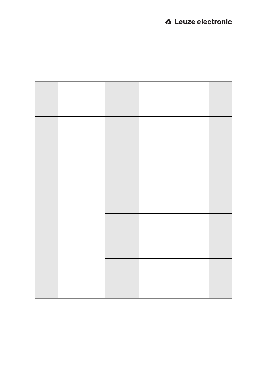
Display and control panel
Decoder table
In the Decoder table submenu, 4 different code type definitions can be stored. Bar codes
that have been read can o nly be decoded if they correspond to one of the definitions stored
here.
Table 8.2: Decoder table submenu
Level 3 Level 4 Level 5 Selection/configuration option
Max. no. of
labels
Decoder 1 Symbology
(Code type)
Number of digits Interval mode OFF/ON
Digits 1 0 to 64 characters
Digits 2 0 to 64 characters
Digits 3 0 to 64 characters
Digits 4 0 to 64 characters
Digits 5 0 to 64 characters
Reading reliability Value from 2 to 100
Description
Value between 0 and 64
The value set here specifies the maximum
number of labels that should be detected
for each reading gate.
No code
Code 2 of 5 interleaved
Code 39
Code 32
Code UPC
Code EAN
Code 128
EAN Addendum
Codabar
Code 93
GS1 DataBar Omnidirectional
GS1 DataBar Limited
GS1 DataBar Expanded
No code
If
all subsequent decoders are deactivated.
With the
and 2 define a range of character numbers
that are to be read.
First decodable number of characters or
lower range limit.
Second decodable number of characters or
upper range limit.
Third decodable number of characters.
Fourth decodable number of characters.
Fifth decodable number of characters.
Number or scans required to reliably detect
a label.
is configured, the current and
ON
setting, the values in digits 1
Standard
1
Code 2/5i
OFF
10
0
0
0
0
4
96 BCL 548i Leuze electronic
Page 99

Table 8.2: Decoder table submenu
Display and control panel
Level 3 Level 4 Level 5 Selection/configuration option
Check digit method Standard
Check digit transm. Standard
Decoder 2 Symbology as decoder 1 Code 39
Number of digits
Reading reliability
Check digit method
Check digit transm.
Decoder 3 Symbology as decoder 1 Code 128
Number of digits
Reading reliability
Check digit method
Check digit transm.
Interval mode OFF/ON ON
Digits 1 0 to 64 characters 4
Digits 2 0 to 64 characters 30
Digits 3 0 to 64 characters 0
Digits 4 0 to 64 characters 0
Digits 5 0 to 64 characters 0
Interval mode OFF/ON ON
Digits 1 0 to 64 characters 4
Digits 2 0 to 64 characters 63
Digits 3 0 to 64 characters 0
Digits 4 0 to 64 characters 0
Digits 5 0 to 64 characters 0
Description
No check
Depending on the symbology (code type)
selected for the decoder, further calculation
algorithms can be selected here.
Check digit method used for the decoding
of the bar code that has been read.
Standard
If
method intended for the respective code
type is used.
Not standard
Specifies whether the check digit is transmitted. Standard means that the transmission matches the standard intended for
the respective code type.
Value from 2 to 100 4
as decoder 1 Standard
as decoder 1 Standard
Value from 2 to 100 4
as decoder 1 Standard
as decoder 1 Standard
is set, the check digit
Standard
Standard
Standard
TNT 35/7-24V
Leuze electronic BCL 548i 97
Page 100

Display and control panel
Table 8.2: Decoder table submenu
Level 3 Level 4 Level 5 Selection/configuration option
Decoder 4 Symbology as decoder 1 Code UPC
Number of digits
Reading reliability
Check digit method
Check digit transm.
Interval mode OFF/ON OFF
Digits 1 0 to 64 characters 8
Digits 2 0 to 64 characters 0
Digits 3 0 to 64 characters 0
Digits 4 0 to 64 characters 0
Digits 5 0 to 64 characters 0
Description
Value from 2 to 100 4
as decoder 1 Standard
as decoder 1 Standard
Standard
98 BCL 548i Leuze electronic
 Loading...