

Leuze LES 36 Series, LES 36HI Series Original Operating Instructions
LES - Line Edge Sensor
Light section sensors
en 05-2018/03 50116497
We reserve the right
to make technical changes
Original operating instructions

© 2018
Leuze electronic GmbH + Co. KG
In der Braike 1
D-73277 Owen / Germany
Phone: +49 7021 573-0
Fax: +49 7021 573-199
http://www.leuze.com
info@leuze.com
Leuze electronic LES 36

Table of contents
Figures and tables . . . . . . . . . . . . . . . . . . . . . . . . . . . . . . . . . . . . . 8
1 General information . . . . . . . . . . . . . . . . . . . . . . . . . . . . . . . . . . . 10
1.1 Explanation of symbols . . . . . . . . . . . . . . . . . . . . . . . . . . . . . . . . . . . . . . . . . . . . . . . . . . 10
1.2 Declaration of Conformity . . . . . . . . . . . . . . . . . . . . . . . . . . . . . . . . . . . . . . . . . . . . . . . . 10
2 Safety . . . . . . . . . . . . . . . . . . . . . . . . . . . . . . . . . . . . . . . . . . . . . . 11
2.1 Intended use . . . . . . . . . . . . . . . . . . . . . . . . . . . . . . . . . . . . . . . . . . . . . . . . . . . . . . . . . . 11
2.2 Foreseeable misuse. . . . . . . . . . . . . . . . . . . . . . . . . . . . . . . . . . . . . . . . . . . . . . . . . . . . . 12
2.3 Competent persons . . . . . . . . . . . . . . . . . . . . . . . . . . . . . . . . . . . . . . . . . . . . . . . . . . . . . 12
2.4 Exemption of liability . . . . . . . . . . . . . . . . . . . . . . . . . . . . . . . . . . . . . . . . . . . . . . . . . . . . 13
2.5 Laser safety notices. . . . . . . . . . . . . . . . . . . . . . . . . . . . . . . . . . . . . . . . . . . . . . . . . . . . . 13
3 Operating principle . . . . . . . . . . . . . . . . . . . . . . . . . . . . . . . . . . . . 16
3.1 Generation of 2D profiles. . . . . . . . . . . . . . . . . . . . . . . . . . . . . . . . . . . . . . . . . . . . . . . . . 16
3.2 Limits of light section sensors . . . . . . . . . . . . . . . . . . . . . . . . . . . . . . . . . . . . . . . . . . . . 17
3.2.1 Occlusion . . . . . . . . . . . . . . . . . . . . . . . . . . . . . . . . . . . . . . . . . . . . . . . . . . . . . . . . . . . . . 17
3.2.2 Resolution . . . . . . . . . . . . . . . . . . . . . . . . . . . . . . . . . . . . . . . . . . . . . . . . . . . . . . . . . . . . . 19
4 Device description . . . . . . . . . . . . . . . . . . . . . . . . . . . . . . . . . . . . 20
4.1 Overview of light section sensors . . . . . . . . . . . . . . . . . . . . . . . . . . . . . . . . . . . . . . . . . . 20
4.1.1 Mechanical design . . . . . . . . . . . . . . . . . . . . . . . . . . . . . . . . . . . . . . . . . . . . . . . . . . . . . . 20
4.1.2 General performance characteristics . . . . . . . . . . . . . . . . . . . . . . . . . . . . . . . . . . . . . . . . 20
4.1.3 Line Edge Sensor - LES . . . . . . . . . . . . . . . . . . . . . . . . . . . . . . . . . . . . . . . . . . . . . . . . . . 21
4.2 Operating the sensor . . . . . . . . . . . . . . . . . . . . . . . . . . . . . . . . . . . . . . . . . . . . . . . . . . . . 22
4.2.1 Connection to PC / process control . . . . . . . . . . . . . . . . . . . . . . . . . . . . . . . . . . . . . . . . . 22
4.2.2 Activation - laser on/off. . . . . . . . . . . . . . . . . . . . . . . . . . . . . . . . . . . . . . . . . . . . . . . . . . . 22
4.2.3 Triggering - Free Running . . . . . . . . . . . . . . . . . . . . . . . . . . . . . . . . . . . . . . . . . . . . . . . . . 23
4.2.4 Cascading. . . . . . . . . . . . . . . . . . . . . . . . . . . . . . . . . . . . . . . . . . . . . . . . . . . . . . . . . . . . . 24
4.3 Measurement functions: LES . . . . . . . . . . . . . . . . . . . . . . . . . . . . . . . . . . . . . . . . . . . . . 25
4.3.1 Inspection Task. . . . . . . . . . . . . . . . . . . . . . . . . . . . . . . . . . . . . . . . . . . . . . . . . . . . . . . . . 26
Possible measure against laser occlusion . . . . . . . . . . . . . . . . . . . . . . . . . . . . . . . . . . . . . . . . . . . . . . . 18
Possible measures against receiver occlusion. . . . . . . . . . . . . . . . . . . . . . . . . . . . . . . . . . . . . . . . . . . . 18
Specific performance characteristics. . . . . . . . . . . . . . . . . . . . . . . . . . . . . . . . . . . . . . . . . . . . . . . . . . . 21
Typical areas of application . . . . . . . . . . . . . . . . . . . . . . . . . . . . . . . . . . . . . . . . . . . . . . . . . . . . . . . . . . 21
Configuration . . . . . . . . . . . . . . . . . . . . . . . . . . . . . . . . . . . . . . . . . . . . . . . . . . . . . . . . . . . . . . . . . . . . . 22
Measurement operation . . . . . . . . . . . . . . . . . . . . . . . . . . . . . . . . . . . . . . . . . . . . . . . . . . . . . . . . . . . . . 22
PROFIBUS trigger . . . . . . . . . . . . . . . . . . . . . . . . . . . . . . . . . . . . . . . . . . . . . . . . . . . . . . . . . . . . . . . . . 24
Trigger settings . . . . . . . . . . . . . . . . . . . . . . . . . . . . . . . . . . . . . . . . . . . . . . . . . . . . . . . . . . . . . . . . . . . 24
Cascading settings. . . . . . . . . . . . . . . . . . . . . . . . . . . . . . . . . . . . . . . . . . . . . . . . . . . . . . . . . . . . . . . . . 24
Functional principle of object and edge detection with the LES . . . . . . . . . . . . . . . . . . . . . . . . . . . . . . 25
TNT 35/7-24V
Leuze electronic LES 36 1

Table of contents
4.3.2 Edge Analysis Window (EAW). . . . . . . . . . . . . . . . . . . . . . . . . . . . . . . . . . . . . . . . . . . . . . 26
4.3.3 Definition of EAWs and their analysis results . . . . . . . . . . . . . . . . . . . . . . . . . . . . . . . . . . 27
Characteristics of EAWs . . . . . . . . . . . . . . . . . . . . . . . . . . . . . . . . . . . . . . . . . . . . . . . . . . . . . . . . . . . . 26
Edge detection . . . . . . . . . . . . . . . . . . . . . . . . . . . . . . . . . . . . . . . . . . . . . . . . . . . . . . . . . . . . . . . . . . . . 27
Relative window positioning . . . . . . . . . . . . . . . . . . . . . . . . . . . . . . . . . . . . . . . . . . . . . . . . . . . . . . . . . 30
Object detection . . . . . . . . . . . . . . . . . . . . . . . . . . . . . . . . . . . . . . . . . . . . . . . . . . . . . . . . . . . . . . . . . . 31
4.3.4 Application examples for EAWs . . . . . . . . . . . . . . . . . . . . . . . . . . . . . . . . . . . . . . . . . . . . 32
Application example: web-edge measurement . . . . . . . . . . . . . . . . . . . . . . . . . . . . . . . . . . . . . . . . . . . 32
Application example: height and width measurement of a cubic object . . . . . . . . . . . . . . . . . . . . . . . . 33
4.4 Analysis Window (AW) . . . . . . . . . . . . . . . . . . . . . . . . . . . . . . . . . . . . . . . . . . . . . . . . . . . 34
5 Installation and mounting . . . . . . . . . . . . . . . . . . . . . . . . . . . . . . . 35
5.1 Storage, transportation . . . . . . . . . . . . . . . . . . . . . . . . . . . . . . . . . . . . . . . . . . . . . . . . . . 35
Unpacking . . . . . . . . . . . . . . . . . . . . . . . . . . . . . . . . . . . . . . . . . . . . . . . . . . . . . . . . . . . . . . . . . . . . . . . 35
5.2 Mounting the LES . . . . . . . . . . . . . . . . . . . . . . . . . . . . . . . . . . . . . . . . . . . . . . . . . . . . . . 36
5.2.1 BT 56 mounting device. . . . . . . . . . . . . . . . . . . . . . . . . . . . . . . . . . . . . . . . . . . . . . . . . . . 37
5.2.2 BT 59 mounting device. . . . . . . . . . . . . . . . . . . . . . . . . . . . . . . . . . . . . . . . . . . . . . . . . . . 38
5.3 Device arrangement. . . . . . . . . . . . . . . . . . . . . . . . . . . . . . . . . . . . . . . . . . . . . . . . . . . . . 39
5.3.1 Selecting a mounting location . . . . . . . . . . . . . . . . . . . . . . . . . . . . . . . . . . . . . . . . . . . . . 39
5.3.2 Aligning the sensor . . . . . . . . . . . . . . . . . . . . . . . . . . . . . . . . . . . . . . . . . . . . . . . . . . . . . . 39
5.4 Attach laser warning sign . . . . . . . . . . . . . . . . . . . . . . . . . . . . . . . . . . . . . . . . . . . . . . . . 40
5.5 Cleaning . . . . . . . . . . . . . . . . . . . . . . . . . . . . . . . . . . . . . . . . . . . . . . . . . . . . . . . . . . . . . . 40
6 Electrical connection . . . . . . . . . . . . . . . . . . . . . . . . . . . . . . . . . . 41
6.1 Safety notices . . . . . . . . . . . . . . . . . . . . . . . . . . . . . . . . . . . . . . . . . . . . . . . . . . . . . . . . . 42
6.2 Shielding and line lengths . . . . . . . . . . . . . . . . . . . . . . . . . . . . . . . . . . . . . . . . . . . . . . . . 43
Shielding: . . . . . . . . . . . . . . . . . . . . . . . . . . . . . . . . . . . . . . . . . . . . . . . . . . . . . . . . . . . . . . . . . . . . . . . . 43
General shielding information: . . . . . . . . . . . . . . . . . . . . . . . . . . . . . . . . . . . . . . . . . . . . . . . . . . . . . . . . 44
Connect the ground potential to the light section sensors . . . . . . . . . . . . . . . . . . . . . . . . . . . . . . . . . . 44
Connecting the cable shielding in the switch cabinet . . . . . . . . . . . . . . . . . . . . . . . . . . . . . . . . . . . . . . 45
Connecting the cable shielding to the PLC . . . . . . . . . . . . . . . . . . . . . . . . . . . . . . . . . . . . . . . . . . . . . . 45
6.3 Connecting . . . . . . . . . . . . . . . . . . . . . . . . . . . . . . . . . . . . . . . . . . . . . . . . . . . . . . . . . . . . 46
6.3.1 Connection X1 - logic and power . . . . . . . . . . . . . . . . . . . . . . . . . . . . . . . . . . . . . . . . . . . 46
6.3.2 Connection X2 - Ethernet . . . . . . . . . . . . . . . . . . . . . . . . . . . . . . . . . . . . . . . . . . . . . . . . . 47
6.3.3 Connection X3 - switching inputs/outputs (LES 36…/VC6) . . . . . . . . . . . . . . . . . . . . . . . 48
6.3.4 Connection X4 - PROFIBUS DP (LES 36…/PB) . . . . . . . . . . . . . . . . . . . . . . . . . . . . . . . . 49
6.3.5 Connection X4 - voltage/current output (LES 36…/VC6) . . . . . . . . . . . . . . . . . . . . . . . . . 50
Power supply . . . . . . . . . . . . . . . . . . . . . . . . . . . . . . . . . . . . . . . . . . . . . . . . . . . . . . . . . . . . . . . . . . . . . 46
Activation input InAct . . . . . . . . . . . . . . . . . . . . . . . . . . . . . . . . . . . . . . . . . . . . . . . . . . . . . . . . . . . . . . . 46
Trigger input InTrig. . . . . . . . . . . . . . . . . . . . . . . . . . . . . . . . . . . . . . . . . . . . . . . . . . . . . . . . . . . . . . . . . 46
Cascading output OutCas . . . . . . . . . . . . . . . . . . . . . . . . . . . . . . . . . . . . . . . . . . . . . . . . . . . . . . . . . . . 47
Output "ready" OutReady . . . . . . . . . . . . . . . . . . . . . . . . . . . . . . . . . . . . . . . . . . . . . . . . . . . . . . . . . . . 47
Ethernet cable assignment. . . . . . . . . . . . . . . . . . . . . . . . . . . . . . . . . . . . . . . . . . . . . . . . . . . . . . . . . . . 47
Switching outputs of connection X3 . . . . . . . . . . . . . . . . . . . . . . . . . . . . . . . . . . . . . . . . . . . . . . . . . . . 48
Switching inputs of connection X3 . . . . . . . . . . . . . . . . . . . . . . . . . . . . . . . . . . . . . . . . . . . . . . . . . . . . 48
Characteristic curve of analog output . . . . . . . . . . . . . . . . . . . . . . . . . . . . . . . . . . . . . . . . . . . . . . . . . . 50
TNT 35/7-24V
Leuze electronic LES 36 2

Table of contents
7 Display and control panel . . . . . . . . . . . . . . . . . . . . . . . . . . . . . . . 52
7.1 Indicators and operational controls . . . . . . . . . . . . . . . . . . . . . . . . . . . . . . . . . . . . . . . . 52
7.1.1 LED status indicators . . . . . . . . . . . . . . . . . . . . . . . . . . . . . . . . . . . . . . . . . . . . . . . . . . . . 52
7.1.2 Control buttons . . . . . . . . . . . . . . . . . . . . . . . . . . . . . . . . . . . . . . . . . . . . . . . . . . . . . . . . . 52
7.1.3 Indicators in the display . . . . . . . . . . . . . . . . . . . . . . . . . . . . . . . . . . . . . . . . . . . . . . . . . . 53
7.2 Menu description . . . . . . . . . . . . . . . . . . . . . . . . . . . . . . . . . . . . . . . . . . . . . . . . . . . . . . . 55
7.2.1 Structure . . . . . . . . . . . . . . . . . . . . . . . . . . . . . . . . . . . . . . . . . . . . . . . . . . . . . . . . . . . . . . 55
7.2.2 Operation/navigation . . . . . . . . . . . . . . . . . . . . . . . . . . . . . . . . . . . . . . . . . . . . . . . . . . . . 58
7.3 Reset to factory settings . . . . . . . . . . . . . . . . . . . . . . . . . . . . . . . . . . . . . . . . . . . . . . . . . 59
8 Commissioning and configuration. . . . . . . . . . . . . . . . . . . . . . . . . 60
8.1 Switching on. . . . . . . . . . . . . . . . . . . . . . . . . . . . . . . . . . . . . . . . . . . . . . . . . . . . . . . . . . . 60
8.2 Establish connection to PC . . . . . . . . . . . . . . . . . . . . . . . . . . . . . . . . . . . . . . . . . . . . . . . 60
8.3 Commissioning . . . . . . . . . . . . . . . . . . . . . . . . . . . . . . . . . . . . . . . . . . . . . . . . . . . . . . . . 62
Alignment aid . . . . . . . . . . . . . . . . . . . . . . . . . . . . . . . . . . . . . . . . . . . . . . . . . . . . . . . . . . . . . . . . . . . . . 53
Status indicator . . . . . . . . . . . . . . . . . . . . . . . . . . . . . . . . . . . . . . . . . . . . . . . . . . . . . . . . . . . . . . . . . . . 53
Command mode . . . . . . . . . . . . . . . . . . . . . . . . . . . . . . . . . . . . . . . . . . . . . . . . . . . . . . . . . . . . . . . . . . 54
Menu navigation. . . . . . . . . . . . . . . . . . . . . . . . . . . . . . . . . . . . . . . . . . . . . . . . . . . . . . . . . . . . . . . . . . . 58
Selecting values or selection parameters for editing . . . . . . . . . . . . . . . . . . . . . . . . . . . . . . . . . . . . . . . 58
Editing value parameters . . . . . . . . . . . . . . . . . . . . . . . . . . . . . . . . . . . . . . . . . . . . . . . . . . . . . . . . . . . . 58
Editing selection parameters . . . . . . . . . . . . . . . . . . . . . . . . . . . . . . . . . . . . . . . . . . . . . . . . . . . . . . . . . 58
Interrupting a reset . . . . . . . . . . . . . . . . . . . . . . . . . . . . . . . . . . . . . . . . . . . . . . . . . . . . . . . . . . . . . . . . . 59
Executing a reset . . . . . . . . . . . . . . . . . . . . . . . . . . . . . . . . . . . . . . . . . . . . . . . . . . . . . . . . . . . . . . . . . . 59
Setting the default gateway . . . . . . . . . . . . . . . . . . . . . . . . . . . . . . . . . . . . . . . . . . . . . . . . . . . . . . . . . . 61
Setting an alternative IP address on the PC . . . . . . . . . . . . . . . . . . . . . . . . . . . . . . . . . . . . . . . . . . . . . 61
9 LESsoft configuration software. . . . . . . . . . . . . . . . . . . . . . . . . . . 63
9.1 System requirements. . . . . . . . . . . . . . . . . . . . . . . . . . . . . . . . . . . . . . . . . . . . . . . . . . . . 63
9.2 Installation . . . . . . . . . . . . . . . . . . . . . . . . . . . . . . . . . . . . . . . . . . . . . . . . . . . . . . . . . . . . 63
9.2.1 Possible error message . . . . . . . . . . . . . . . . . . . . . . . . . . . . . . . . . . . . . . . . . . . . . . . . . . 69
9.2.2 Device list update . . . . . . . . . . . . . . . . . . . . . . . . . . . . . . . . . . . . . . . . . . . . . . . . . . . . . . . 70
9.3 Starting LESsoft/Communication tab . . . . . . . . . . . . . . . . . . . . . . . . . . . . . . . . . . . . . . . 71
PROFIBUS settings (only LES 36/PB and LES 36HI/PB). . . . . . . . . . . . . . . . . . . . . . . . . . . . . . . . . . . . 73
9.4 Parameter settings/Parameters tab . . . . . . . . . . . . . . . . . . . . . . . . . . . . . . . . . . . . . . . . 74
9.4.1 Standard tab - Task Parameters panel. . . . . . . . . . . . . . . . . . . . . . . . . . . . . . . . . . . . . . . 74
Leuze electronic LES 36 3
Inspection Task Selection . . . . . . . . . . . . . . . . . . . . . . . . . . . . . . . . . . . . . . . . . . . . . . . . . . . . . . . . . . . 74
Operation Mode . . . . . . . . . . . . . . . . . . . . . . . . . . . . . . . . . . . . . . . . . . . . . . . . . . . . . . . . . . . . . . . . . . . 75
Activation . . . . . . . . . . . . . . . . . . . . . . . . . . . . . . . . . . . . . . . . . . . . . . . . . . . . . . . . . . . . . . . . . . . . . . . . 75
Trigger Output Mode . . . . . . . . . . . . . . . . . . . . . . . . . . . . . . . . . . . . . . . . . . . . . . . . . . . . . . . . . . . . . . . 75
Light Exposure . . . . . . . . . . . . . . . . . . . . . . . . . . . . . . . . . . . . . . . . . . . . . . . . . . . . . . . . . . . . . . . . . . . . 75
Field of View. . . . . . . . . . . . . . . . . . . . . . . . . . . . . . . . . . . . . . . . . . . . . . . . . . . . . . . . . . . . . . . . . . . . . . 76
Apply Settings . . . . . . . . . . . . . . . . . . . . . . . . . . . . . . . . . . . . . . . . . . . . . . . . . . . . . . . . . . . . . . . . . . . . 76
TNT 35/7-24V

Table of contents
9.4.2 Standard tab - Analysis Functions panel . . . . . . . . . . . . . . . . . . . . . . . . . . . . . . . . . . . . . 76
Edit Analysis Windows . . . . . . . . . . . . . . . . . . . . . . . . . . . . . . . . . . . . . . . . . . . . . . . . . . . . . . . . . . . . . . 76
Using the mouse . . . . . . . . . . . . . . . . . . . . . . . . . . . . . . . . . . . . . . . . . . . . . . . . . . . . . . . . . . . . . . . . . . 77
Keyboard input. . . . . . . . . . . . . . . . . . . . . . . . . . . . . . . . . . . . . . . . . . . . . . . . . . . . . . . . . . . . . . . . . . . . 78
Position type . . . . . . . . . . . . . . . . . . . . . . . . . . . . . . . . . . . . . . . . . . . . . . . . . . . . . . . . . . . . . . . . . . . . . 78
Relative to Edge . . . . . . . . . . . . . . . . . . . . . . . . . . . . . . . . . . . . . . . . . . . . . . . . . . . . . . . . . . . . . . . . . . . 78
Offset X / Offset Z . . . . . . . . . . . . . . . . . . . . . . . . . . . . . . . . . . . . . . . . . . . . . . . . . . . . . . . . . . . . . . . . . 78
Edge Detection Definitions . . . . . . . . . . . . . . . . . . . . . . . . . . . . . . . . . . . . . . . . . . . . . . . . . . . . . . . . . . 78
Analysis Window Definitions . . . . . . . . . . . . . . . . . . . . . . . . . . . . . . . . . . . . . . . . . . . . . . . . . . . . . . . . . 79
Edit Logical Combinations . . . . . . . . . . . . . . . . . . . . . . . . . . . . . . . . . . . . . . . . . . . . . . . . . . . . . . . . . . . 80
Edge State (result of edge and object detection) . . . . . . . . . . . . . . . . . . . . . . . . . . . . . . . . . . . . . . . . . 80
Object Point/EAW State (result of edge detection) . . . . . . . . . . . . . . . . . . . . . . . . . . . . . . . . . . . . . . . . 81
Show Edge. . . . . . . . . . . . . . . . . . . . . . . . . . . . . . . . . . . . . . . . . . . . . . . . . . . . . . . . . . . . . . . . . . . . . . . 81
X, Width (X), Z, Height (Z) . . . . . . . . . . . . . . . . . . . . . . . . . . . . . . . . . . . . . . . . . . . . . . . . . . . . . . . . . . . . 82
Profibus Inputs 1 , Profibus Inputs 2 . . . . . . . . . . . . . . . . . . . . . . . . . . . . . . . . . . . . . . . . . . . . . . . . . . . 82
Application example 1: web edge measurement . . . . . . . . . . . . . . . . . . . . . . . . . . . . . . . . . . . . . . . . . . 83
Application example 2: height and width monitoring of cubic objects . . . . . . . . . . . . . . . . . . . . . . . . . 84
Additional object detection with LES sensors . . . . . . . . . . . . . . . . . . . . . . . . . . . . . . . . . . . . . . . . . . . . 85
EAW1 … EAW4, AW05 … AW08. . . . . . . . . . . . . . . . . . . . . . . . . . . . . . . . . . . . . . . . . . . . . . . . . . . . . . 85
AW Logic . . . . . . . . . . . . . . . . . . . . . . . . . . . . . . . . . . . . . . . . . . . . . . . . . . . . . . . . . . . . . . . . . . . . . . . . 85
Analysis Depth . . . . . . . . . . . . . . . . . . . . . . . . . . . . . . . . . . . . . . . . . . . . . . . . . . . . . . . . . . . . . . . . . . . . 85
AW Logic Analysis Depth (result of object detection) . . . . . . . . . . . . . . . . . . . . . . . . . . . . . . . . . . . . . . 86
Application example 3: width monitoring of cubic objects with object detection (narrow objects
are not to be detected) . . . . . . . . . . . . . . . . . . . . . . . . . . . . . . . . . . . . . . . . . . . . . . . . . . . . . . . . . . . . . 87
9.4.3 Standard tab - Single Shot Mode panel . . . . . . . . . . . . . . . . . . . . . . . . . . . . . . . . . . . . . . 89
9.4.4 Standard tab - Global Parameters panel . . . . . . . . . . . . . . . . . . . . . . . . . . . . . . . . . . . . . 89
9.4.5 Analog Output tab - configuring the analog output (only LES 36…/VC) . . . . . . . . . . . . . 90
Edge. . . . . . . . . . . . . . . . . . . . . . . . . . . . . . . . . . . . . . . . . . . . . . . . . . . . . . . . . . . . . . . . . . . . . . . . . . . . 90
Output Mode . . . . . . . . . . . . . . . . . . . . . . . . . . . . . . . . . . . . . . . . . . . . . . . . . . . . . . . . . . . . . . . . . . . . . 90
Data . . . . . . . . . . . . . . . . . . . . . . . . . . . . . . . . . . . . . . . . . . . . . . . . . . . . . . . . . . . . . . . . . . . . . . . . . . . . 90
mm For Min. Val. . . . . . . . . . . . . . . . . . . . . . . . . . . . . . . . . . . . . . . . . . . . . . . . . . . . . . . . . . . . . . . . . . . 91
mm For Max. Val. . . . . . . . . . . . . . . . . . . . . . . . . . . . . . . . . . . . . . . . . . . . . . . . . . . . . . . . . . . . . . . . . . . 91
9.5 Menu commands . . . . . . . . . . . . . . . . . . . . . . . . . . . . . . . . . . . . . . . . . . . . . . . . . . . . . . . 92
9.5.1 Saving parameter settings/File menu . . . . . . . . . . . . . . . . . . . . . . . . . . . . . . . . . . . . . . . . 92
9.5.2 Transmitting parameter settings/Configuration menu . . . . . . . . . . . . . . . . . . . . . . . . . . . 92
9.5.3 Zoom and Pan/toolbar . . . . . . . . . . . . . . . . . . . . . . . . . . . . . . . . . . . . . . . . . . . . . . . . . . . 93
9.6 Definition of inspection tasks . . . . . . . . . . . . . . . . . . . . . . . . . . . . . . . . . . . . . . . . . . . . . 93
Typical procedure . . . . . . . . . . . . . . . . . . . . . . . . . . . . . . . . . . . . . . . . . . . . . . . . . . . . . . . . . . . . . . . . . 93
TNT 35/7-24V
10 Integrating the LES in the process control (Ethernet) . . . . . . . . . . 95
10.1 General information . . . . . . . . . . . . . . . . . . . . . . . . . . . . . . . . . . . . . . . . . . . . . . . . . . . . . 95
10.2 Protocol structure: Ethernet . . . . . . . . . . . . . . . . . . . . . . . . . . . . . . . . . . . . . . . . . . . . . . 95
Protocol structure . . . . . . . . . . . . . . . . . . . . . . . . . . . . . . . . . . . . . . . . . . . . . . . . . . . . . . . . . . . . . . . . . 96
10.2.1 Command number . . . . . . . . . . . . . . . . . . . . . . . . . . . . . . . . . . . . . . . . . . . . . . . . . . . . . . 96
10.2.2 Packet number . . . . . . . . . . . . . . . . . . . . . . . . . . . . . . . . . . . . . . . . . . . . . . . . . . . . . . . . . 96
10.2.3 Transaction number . . . . . . . . . . . . . . . . . . . . . . . . . . . . . . . . . . . . . . . . . . . . . . . . . . . . . 96
10.2.4 Status . . . . . . . . . . . . . . . . . . . . . . . . . . . . . . . . . . . . . . . . . . . . . . . . . . . . . . . . . . . . . . . . 97
10.2.5 Encoder High / Low . . . . . . . . . . . . . . . . . . . . . . . . . . . . . . . . . . . . . . . . . . . . . . . . . . . . . 97
10.2.6 Scan number. . . . . . . . . . . . . . . . . . . . . . . . . . . . . . . . . . . . . . . . . . . . . . . . . . . . . . . . . . . 98
Leuze electronic LES 36 4
Header . . . . . . . . . . . . . . . . . . . . . . . . . . . . . . . . . . . . . . . . . . . . . . . . . . . . . . . . . . . . . . . . . . . . . . . . . . 96

Table of contents
10.2.7 Type . . . . . . . . . . . . . . . . . . . . . . . . . . . . . . . . . . . . . . . . . . . . . . . . . . . . . . . . . . . . . . . . . 98
10.2.8 Number of user data words . . . . . . . . . . . . . . . . . . . . . . . . . . . . . . . . . . . . . . . . . . . . . . . 98
10.2.9 Evaluation telegram . . . . . . . . . . . . . . . . . . . . . . . . . . . . . . . . . . . . . . . . . . . . . . . . . . . . . 98
10.3 Ethernet commands . . . . . . . . . . . . . . . . . . . . . . . . . . . . . . . . . . . . . . . . . . . . . . . . . . . 100
10.3.1 Elementary commands . . . . . . . . . . . . . . . . . . . . . . . . . . . . . . . . . . . . . . . . . . . . . . . . . . 101
10.3.2 Commands in command mode . . . . . . . . . . . . . . . . . . . . . . . . . . . . . . . . . . . . . . . . . . . 102
10.3.3 Explanation of user data in command mode (command parameters) . . . . . . . . . . . . . . 103
10.3.4 Commands in measure mode. . . . . . . . . . . . . . . . . . . . . . . . . . . . . . . . . . . . . . . . . . . . . 111
10.3.5 Explanation of user data in measure mode (command parameters) . . . . . . . . . . . . . . . 112
10.4 Working with the protocol . . . . . . . . . . . . . . . . . . . . . . . . . . . . . . . . . . . . . . . . . . . . . . . 113
10.5 Operation with LxS_Lib.dll . . . . . . . . . . . . . . . . . . . . . . . . . . . . . . . . . . . . . . . . . . . . . . 114
10.6 Operation with native C++ DLL . . . . . . . . . . . . . . . . . . . . . . . . . . . . . . . . . . . . . . . . . . . 114
10.7 Additional support when integrating sensors. . . . . . . . . . . . . . . . . . . . . . . . . . . . . . . . 114
Set Laser Gate . . . . . . . . . . . . . . . . . . . . . . . . . . . . . . . . . . . . . . . . . . . . . . . . . . . . . . . . . . . . . . . . . . . 103
Set Actual Inspection Task. . . . . . . . . . . . . . . . . . . . . . . . . . . . . . . . . . . . . . . . . . . . . . . . . . . . . . . . . . 103
Get Actual Inspection Task . . . . . . . . . . . . . . . . . . . . . . . . . . . . . . . . . . . . . . . . . . . . . . . . . . . . . . . . . 103
Set Scan Number. . . . . . . . . . . . . . . . . . . . . . . . . . . . . . . . . . . . . . . . . . . . . . . . . . . . . . . . . . . . . . . . . 104
Set Single User parameter . . . . . . . . . . . . . . . . . . . . . . . . . . . . . . . . . . . . . . . . . . . . . . . . . . . . . . . . . . 105
Get Single User parameter. . . . . . . . . . . . . . . . . . . . . . . . . . . . . . . . . . . . . . . . . . . . . . . . . . . . . . . . . . 107
Set Single Inspection Task Parameter . . . . . . . . . . . . . . . . . . . . . . . . . . . . . . . . . . . . . . . . . . . . . . . . . 108
Get Single Inspection Task Parameter. . . . . . . . . . . . . . . . . . . . . . . . . . . . . . . . . . . . . . . . . . . . . . . . . 110
Ethernet Activation . . . . . . . . . . . . . . . . . . . . . . . . . . . . . . . . . . . . . . . . . . . . . . . . . . . . . . . . . . . . . . . . 112
Command without user data . . . . . . . . . . . . . . . . . . . . . . . . . . . . . . . . . . . . . . . . . . . . . . . . . . . . . . . . 113
Command with user data . . . . . . . . . . . . . . . . . . . . . . . . . . . . . . . . . . . . . . . . . . . . . . . . . . . . . . . . . . . 113
Access . . . . . . . . . . . . . . . . . . . . . . . . . . . . . . . . . . . . . . . . . . . . . . . . . . . . . . . . . . . . . . . . . . . . . . . . . 114
11 Integration of the LES 36…/PB in the PROFIBUS . . . . . . . . . . . . 115
11.1 General information . . . . . . . . . . . . . . . . . . . . . . . . . . . . . . . . . . . . . . . . . . . . . . . . . . . . 115
Characteristics of LES 36…/PB . . . . . . . . . . . . . . . . . . . . . . . . . . . . . . . . . . . . . . . . . . . . . . . . . . . . . . 115
11.2 PROFIBUS address assignment . . . . . . . . . . . . . . . . . . . . . . . . . . . . . . . . . . . . . . . . . . 116
Automatic address assignment . . . . . . . . . . . . . . . . . . . . . . . . . . . . . . . . . . . . . . . . . . . . . . . . . . . . . . 116
Address assignment with LESsoft . . . . . . . . . . . . . . . . . . . . . . . . . . . . . . . . . . . . . . . . . . . . . . . . . . . . 116
Address assignment with membrane keyboard and display . . . . . . . . . . . . . . . . . . . . . . . . . . . . . . . . 116
11.3 General information about the GSD file . . . . . . . . . . . . . . . . . . . . . . . . . . . . . . . . . . . . 117
11.4 Overview of the GSD modules . . . . . . . . . . . . . . . . . . . . . . . . . . . . . . . . . . . . . . . . . . . 118
Output data (from viewing position of control). . . . . . . . . . . . . . . . . . . . . . . . . . . . . . . . . . . . . . . . . . . 118
Input data (from viewing position of control) . . . . . . . . . . . . . . . . . . . . . . . . . . . . . . . . . . . . . . . . . . . . 119
11.5 Description of the output data . . . . . . . . . . . . . . . . . . . . . . . . . . . . . . . . . . . . . . . . . . . 120
PROFIBUS trigger . . . . . . . . . . . . . . . . . . . . . . . . . . . . . . . . . . . . . . . . . . . . . . . . . . . . . . . . . . . . . . . . 120
Activation - Sensor activation . . . . . . . . . . . . . . . . . . . . . . . . . . . . . . . . . . . . . . . . . . . . . . . . . . . . . . . 120
Inspection Tasks - Selection of inspection tasks . . . . . . . . . . . . . . . . . . . . . . . . . . . . . . . . . . . . . . . . . 120
11.6 Description of the input data. . . . . . . . . . . . . . . . . . . . . . . . . . . . . . . . . . . . . . . . . . . . . 121
Leuze electronic LES 36 5
TNT 35/7-24V

Table of contents
11.6.1 Module M1 . . . . . . . . . . . . . . . . . . . . . . . . . . . . . . . . . . . . . . . . . . . . . . . . . . . . . . . . . . . 121
Scan number . . . . . . . . . . . . . . . . . . . . . . . . . . . . . . . . . . . . . . . . . . . . . . . . . . . . . . . . . . . . . . . . . . . . 121
Sensor info . . . . . . . . . . . . . . . . . . . . . . . . . . . . . . . . . . . . . . . . . . . . . . . . . . . . . . . . . . . . . . . . . . . . . . 121
Sensor state . . . . . . . . . . . . . . . . . . . . . . . . . . . . . . . . . . . . . . . . . . . . . . . . . . . . . . . . . . . . . . . . . . . . . 122
Logic . . . . . . . . . . . . . . . . . . . . . . . . . . . . . . . . . . . . . . . . . . . . . . . . . . . . . . . . . . . . . . . . . . . . . . . . . . 122
Object detection . . . . . . . . . . . . . . . . . . . . . . . . . . . . . . . . . . . . . . . . . . . . . . . . . . . . . . . . . . . . . . . . . 122
Measurement value 1 in Edge Analysis Window EAW1 . . . . . . . . . . . . . . . . . . . . . . . . . . . . . . . . . . . . 123
11.6.2 Module M2 . . . . . . . . . . . . . . . . . . . . . . . . . . . . . . . . . . . . . . . . . . . . . . . . . . . . . . . . . . . 123
Measurement value 2 in Edge Analysis Window EAW1 (wEdgeAW1Data2) . . . . . . . . . . . . . . . . . . . . 123
Measurement value 1 in Edge Analysis Window EAW2 (wEdgeAW2Data1) . . . . . . . . . . . . . . . . . . . . 123
Measurement value 2 in Edge Analysis Window EAW2 (wEdgeAW2Data2) . . . . . . . . . . . . . . . . . . . . 123
Measurement value 1 in Edge Analysis Window EAW3 (wEdgeAW3Data1) . . . . . . . . . . . . . . . . . . . . 123
11.6.3 Module M3 . . . . . . . . . . . . . . . . . . . . . . . . . . . . . . . . . . . . . . . . . . . . . . . . . . . . . . . . . . . 124
Measurement value 2 in Edge Analysis Window EAW3 (wEdgeAW3Data2) . . . . . . . . . . . . . . . . . . . . 124
Measurement value 1 in Edge Analysis Window EAW4 (wEdgeAW4Data1) . . . . . . . . . . . . . . . . . . . . 124
Measurement value 2 in Edge Analysis Window EAW4 (wEdgeAW4Data2) . . . . . . . . . . . . . . . . . . . . 124
12 Diagnostics and troubleshooting . . . . . . . . . . . . . . . . . . . . . . . . 125
12.1 General causes of errors . . . . . . . . . . . . . . . . . . . . . . . . . . . . . . . . . . . . . . . . . . . . . . . . 125
12.2 Interface error . . . . . . . . . . . . . . . . . . . . . . . . . . . . . . . . . . . . . . . . . . . . . . . . . . . . . . . . 126
12.3 Error messages in display (starting from firmware V01.40) . . . . . . . . . . . . . . . . . . . . . 127
13 Maintenance . . . . . . . . . . . . . . . . . . . . . . . . . . . . . . . . . . . . . . . . 129
13.1 General maintenance information . . . . . . . . . . . . . . . . . . . . . . . . . . . . . . . . . . . . . . . . . 129
Cleaning . . . . . . . . . . . . . . . . . . . . . . . . . . . . . . . . . . . . . . . . . . . . . . . . . . . . . . . . . . . . . . . . . . . . . . . . 129
13.2 Repairs, servicing . . . . . . . . . . . . . . . . . . . . . . . . . . . . . . . . . . . . . . . . . . . . . . . . . . . . . 129
13.3 Disassembling, packing, disposing . . . . . . . . . . . . . . . . . . . . . . . . . . . . . . . . . . . . . . . 129
Repacking . . . . . . . . . . . . . . . . . . . . . . . . . . . . . . . . . . . . . . . . . . . . . . . . . . . . . . . . . . . . . . . . . . . . . . 129
14 Technical data . . . . . . . . . . . . . . . . . . . . . . . . . . . . . . . . . . . . . . 130
14.1 General technical data. . . . . . . . . . . . . . . . . . . . . . . . . . . . . . . . . . . . . . . . . . . . . . . . . . 130
14.2 Typical measurement range . . . . . . . . . . . . . . . . . . . . . . . . . . . . . . . . . . . . . . . . . . . . . 132
14.3 Dimensioned drawing . . . . . . . . . . . . . . . . . . . . . . . . . . . . . . . . . . . . . . . . . . . . . . . . . . 133
15 Type overview and accessories . . . . . . . . . . . . . . . . . . . . . . . . . 134
15.1 Type overview . . . . . . . . . . . . . . . . . . . . . . . . . . . . . . . . . . . . . . . . . . . . . . . . . . . . . . . . 134
15.1.1 LPS . . . . . . . . . . . . . . . . . . . . . . . . . . . . . . . . . . . . . . . . . . . . . . . . . . . . . . . . . . . . . . . . . 134
15.1.2 LRS . . . . . . . . . . . . . . . . . . . . . . . . . . . . . . . . . . . . . . . . . . . . . . . . . . . . . . . . . . . . . . . . . 134
15.1.3 LES . . . . . . . . . . . . . . . . . . . . . . . . . . . . . . . . . . . . . . . . . . . . . . . . . . . . . . . . . . . . . . . . . 135
15.2 Accessories . . . . . . . . . . . . . . . . . . . . . . . . . . . . . . . . . . . . . . . . . . . . . . . . . . . . . . . . . . 136
15.2.1 Mounting. . . . . . . . . . . . . . . . . . . . . . . . . . . . . . . . . . . . . . . . . . . . . . . . . . . . . . . . . . . . . 136
15.2.2 Accessories – Ready-made cables for voltage supply X1 . . . . . . . . . . . . . . . . . . . . . . . 136
Leuze electronic LES 36 6
Mounting devices . . . . . . . . . . . . . . . . . . . . . . . . . . . . . . . . . . . . . . . . . . . . . . . . . . . . . . . . . . . . . . . . . 136
Contact assignment for connection cable X1 . . . . . . . . . . . . . . . . . . . . . . . . . . . . . . . . . . . . . . . . . . . 136
Order codes of the cables for voltage supply . . . . . . . . . . . . . . . . . . . . . . . . . . . . . . . . . . . . . . . . . . . 136
TNT 35/7-24V

Table of contents
15.2.3 Accessories for Ethernet interface X2. . . . . . . . . . . . . . . . . . . . . . . . . . . . . . . . . . . . . . . 137
Ready-made cables with M 12 connector/open cable end . . . . . . . . . . . . . . . . . . . . . . . . . . . . . . . . . 137
Ready-made cables with M 12 connector/RJ-45 connector . . . . . . . . . . . . . . . . . . . . . . . . . . . . . . . . 137
Ready-made cables with M 12 connector/M12 connector . . . . . . . . . . . . . . . . . . . . . . . . . . . . . . . . . 138
Connectors . . . . . . . . . . . . . . . . . . . . . . . . . . . . . . . . . . . . . . . . . . . . . . . . . . . . . . . . . . . . . . . . . . . . . 138
15.2.4 ccessories - Ready-made cables for X3 (only LES 36…/VC6). . . . . . . . . . . . . . . . . . . . 139
Contact assignment for X3 connection cables . . . . . . . . . . . . . . . . . . . . . . . . . . . . . . . . . . . . . . . . . . 139
Order code of X3 connection cables . . . . . . . . . . . . . . . . . . . . . . . . . . . . . . . . . . . . . . . . . . . . . . . . . . 139
15.2.5 Connection accessories / ready-made cables for X4 (only LES 36…/PB) . . . . . . . . . . . 140
Contact assignment for X4 connection cables . . . . . . . . . . . . . . . . . . . . . . . . . . . . . . . . . . . . . . . . . . 140
Order codes for X4 connection accessories . . . . . . . . . . . . . . . . . . . . . . . . . . . . . . . . . . . . . . . . . . . . 140
Order code of PROFIBUS connection cables for X4 . . . . . . . . . . . . . . . . . . . . . . . . . . . . . . . . . . . . . . 141
15.2.6 Connection accessories / ready-made cables for X4 (only LES 36…/VC6) . . . . . . . . . . 142
Contact assignment for X4 connection cables . . . . . . . . . . . . . . . . . . . . . . . . . . . . . . . . . . . . . . . . . . 142
Order code of X4 connection cables (only LES 36…/VC6) . . . . . . . . . . . . . . . . . . . . . . . . . . . . . . . . . 142
15.2.7 Configuration software . . . . . . . . . . . . . . . . . . . . . . . . . . . . . . . . . . . . . . . . . . . . . . . . . . 143
15.2.8 Configuration memory . . . . . . . . . . . . . . . . . . . . . . . . . . . . . . . . . . . . . . . . . . . . . . . . . . 143
16 Appendix. . . . . . . . . . . . . . . . . . . . . . . . . . . . . . . . . . . . . . . . . . . 144
16.1 Glossary . . . . . . . . . . . . . . . . . . . . . . . . . . . . . . . . . . . . . . . . . . . . . . . . . . . . . . . . . . . . . 144
16.2 Revision History / Feature list . . . . . . . . . . . . . . . . . . . . . . . . . . . . . . . . . . . . . . . . . . . . 145
16.2.1 Firmware . . . . . . . . . . . . . . . . . . . . . . . . . . . . . . . . . . . . . . . . . . . . . . . . . . . . . . . . . . . . . 145
16.2.2 Configuration software . . . . . . . . . . . . . . . . . . . . . . . . . . . . . . . . . . . . . . . . . . . . . . . . . . 146
Index. . . . . . . . . . . . . . . . . . . . . . . . . . . . . . . . . . . . . . . . . . . . . . 148
Leuze electronic LES 36 7
TNT 35/7-24V

Figures and tables
Figures and tables
Figure 2.1: Laser apertures, laser warning signs . . . . . . . . . . . . . . . . . . . . . . . . . . . . . . . . . . . . 14
Figure 2.2: Laser warning and information signs – supplied stick-on labels . . . . . . . . . . . . . . . 15
Figure 3.1: Light section sensor design . . . . . . . . . . . . . . . . . . . . . . . . . . . . . . . . . . . . . . . . . . . 16
Figure 3.2: Occlusion . . . . . . . . . . . . . . . . . . . . . . . . . . . . . . . . . . . . . . . . . . . . . . . . . . . . . . . . . 17
Figure 3.3: Typical resolution LES 36… . . . . . . . . . . . . . . . . . . . . . . . . . . . . . . . . . . . . . . . . . . . 19
Figure 3.4: Typical minimum object size LES 36HI… . . . . . . . . . . . . . . . . . . . . . . . . . . . . . . . . 19
Figure 4.1: Mechanical design of Leuze light section sensors. . . . . . . . . . . . . . . . . . . . . . . . . . 20
Figure 4.2: Activation input signal sequence . . . . . . . . . . . . . . . . . . . . . . . . . . . . . . . . . . . . . . . 22
Figure 4.3: Trigger input signal sequence . . . . . . . . . . . . . . . . . . . . . . . . . . . . . . . . . . . . . . . . . 23
Figure 4.4: Signal sequence for cascading . . . . . . . . . . . . . . . . . . . . . . . . . . . . . . . . . . . . . . . . 24
Figure 4.5: Cascading application example . . . . . . . . . . . . . . . . . . . . . . . . . . . . . . . . . . . . . . . . 24
Figure 4.6: Edge detection with EAWs. . . . . . . . . . . . . . . . . . . . . . . . . . . . . . . . . . . . . . . . . . . . 27
Figure 4.7: Meaning of Sequent Hits for edge detection . . . . . . . . . . . . . . . . . . . . . . . . . . . . . . 28
Figure 4.8: Edge detection with EAWs. . . . . . . . . . . . . . . . . . . . . . . . . . . . . . . . . . . . . . . . . . . . 29
Figure 4.9: Edge detection with varying object position . . . . . . . . . . . . . . . . . . . . . . . . . . . . . . 30
Figure 4.10: Application example: web-edge measurement . . . . . . . . . . . . . . . . . . . . . . . . . . . . 32
Figure 4.11: Application example: height and width measurement of a cubic object . . . . . . . . . 33
Figure 5.1: Device name plate LES . . . . . . . . . . . . . . . . . . . . . . . . . . . . . . . . . . . . . . . . . . . . . . 35
Figure 5.2: Fastening options. . . . . . . . . . . . . . . . . . . . . . . . . . . . . . . . . . . . . . . . . . . . . . . . . . . 36
Figure 5.3: Mounting example LES . . . . . . . . . . . . . . . . . . . . . . . . . . . . . . . . . . . . . . . . . . . . . . 36
Figure 5.4: BT 56 mounting device . . . . . . . . . . . . . . . . . . . . . . . . . . . . . . . . . . . . . . . . . . . . . . 37
Figure 5.5: BT 59 mounting device . . . . . . . . . . . . . . . . . . . . . . . . . . . . . . . . . . . . . . . . . . . . . . 38
Figure 5.6: Alignment to the measuring plane . . . . . . . . . . . . . . . . . . . . . . . . . . . . . . . . . . . . . . 40
Figure 6.1: Location of the electrical connections . . . . . . . . . . . . . . . . . . . . . . . . . . . . . . . . . . . 41
Figure 6.2: Connections of the LES . . . . . . . . . . . . . . . . . . . . . . . . . . . . . . . . . . . . . . . . . . . . . . 41
Table 6.1: Interface version of X3 and X4 . . . . . . . . . . . . . . . . . . . . . . . . . . . . . . . . . . . . . . . . . 42
Table 6.2: Cable lengths and shielding . . . . . . . . . . . . . . . . . . . . . . . . . . . . . . . . . . . . . . . . . . . 43
Figure 6.3: Connecting the ground potential to the light section sensor . . . . . . . . . . . . . . . . . . 44
Figure 6.4: Connecting the cable shielding in the switch cabinet . . . . . . . . . . . . . . . . . . . . . . . 45
Figure 6.5: Connecting the cable shielding to the PLC . . . . . . . . . . . . . . . . . . . . . . . . . . . . . . . 45
Table 6.3: Pin assignment X1 . . . . . . . . . . . . . . . . . . . . . . . . . . . . . . . . . . . . . . . . . . . . . . . . . . 46
Figure 6.6: Internal wiring at X1 . . . . . . . . . . . . . . . . . . . . . . . . . . . . . . . . . . . . . . . . . . . . . . . . . 46
Table 6.4: Pin assignment X2 . . . . . . . . . . . . . . . . . . . . . . . . . . . . . . . . . . . . . . . . . . . . . . . . . . 47
Figure 6.7: HOST / BUS IN cable assignments on RJ-45 . . . . . . . . . . . . . . . . . . . . . . . . . . . . . 47
Table 6.5: Pin assignment X3 . . . . . . . . . . . . . . . . . . . . . . . . . . . . . . . . . . . . . . . . . . . . . . . . . . 48
Table 6.6: Pin assignment X4 for LES 36…/PB . . . . . . . . . . . . . . . . . . . . . . . . . . . . . . . . . . . . 49
Table 6.7: Pin assignment X4 for LES 36…/VC6 . . . . . . . . . . . . . . . . . . . . . . . . . . . . . . . . . . . 50
Figure 6.8: Response of analog output LES. . . . . . . . . . . . . . . . . . . . . . . . . . . . . . . . . . . . . . . . 51
Figure 7.1: Indicator and operating elements of the LES. . . . . . . . . . . . . . . . . . . . . . . . . . . . . . 52
Table 7.1: LED function indicator . . . . . . . . . . . . . . . . . . . . . . . . . . . . . . . . . . . . . . . . . . . . . . . 52
Table 7.2: Menu structure . . . . . . . . . . . . . . . . . . . . . . . . . . . . . . . . . . . . . . . . . . . . . . . . . . . . . 55
Table 8.1: Address allocation in the Ethernet . . . . . . . . . . . . . . . . . . . . . . . . . . . . . . . . . . . . . . 60
Figure 9.1: Initial screen LESsoft . . . . . . . . . . . . . . . . . . . . . . . . . . . . . . . . . . . . . . . . . . . . . . . . 71
Figure 9.2: PROFIBUS settings . . . . . . . . . . . . . . . . . . . . . . . . . . . . . . . . . . . . . . . . . . . . . . . . . 73
Figure 9.3: Parameter settings LESsoft . . . . . . . . . . . . . . . . . . . . . . . . . . . . . . . . . . . . . . . . . . . 74
Figure 9.4: Edit Analysis Windows . . . . . . . . . . . . . . . . . . . . . . . . . . . . . . . . . . . . . . . . . . . . . . . 77
Figure 9.5: ’Edge Analysis Window Combination Tables’ window . . . . . . . . . . . . . . . . . . . . . . 80
TNT 35/7-24V
Leuze electronic LES 36 8

Figures and tables
Figure 9.6: Display of the edge positions (green and blue) in the 2D display . . . . . . . . . . . . . . 81
Figure 9.7: Application example 1: web edge measurement . . . . . . . . . . . . . . . . . . . . . . . . . . . 83
Figure 9.8: Application example 2: height and width monitoring of cubic objects . . . . . . . . . . 84
Figure 9.9: Application example 3.1: width monitoring of cubic objects with object
Figure 9.10: Application example 3.2: width monitoring of cubic objects with object
Figure 9.11: Parameter settings in LRSsoft . . . . . . . . . . . . . . . . . . . . . . . . . . . . . . . . . . . . . . . . . 90
Figure 9.12: Zoom function . . . . . . . . . . . . . . . . . . . . . . . . . . . . . . . . . . . . . . . . . . . . . . . . . . . . . 93
Table 10.1: Connection commands . . . . . . . . . . . . . . . . . . . . . . . . . . . . . . . . . . . . . . . . . . . . . 101
Table 10.2: Command mode control commands . . . . . . . . . . . . . . . . . . . . . . . . . . . . . . . . . . . 101
Table 10.3: Sensor control commands . . . . . . . . . . . . . . . . . . . . . . . . . . . . . . . . . . . . . . . . . . . 102
Table 10.4: Commands in measure mode . . . . . . . . . . . . . . . . . . . . . . . . . . . . . . . . . . . . . . . . 111
Figure 11.1: PROFIBUS address assignment with LESsoft . . . . . . . . . . . . . . . . . . . . . . . . . . . . 116
Table 11.1: PROFIBUS - Overview of output data (from viewing position of control) . . . . . . . 118
Table 11.2: Input data byte
Table 11.3: Input data byte
Table 11.4: Input data byte
Table 11.5: Input data byte
Table 11.6: Input data bytes
Table 12.1: General causes of errors . . . . . . . . . . . . . . . . . . . . . . . . . . . . . . . . . . . . . . . . . . . . 125
Table 12.2: Interface error . . . . . . . . . . . . . . . . . . . . . . . . . . . . . . . . . . . . . . . . . . . . . . . . . . . . . 126
Table 12.3: Error messages in display . . . . . . . . . . . . . . . . . . . . . . . . . . . . . . . . . . . . . . . . . . . 127
Figure 14.1: Typical measurement range LES 36. . . . . . . . . . . . . . . . . . . . . . . . . . . . . . . . . . . . 132
Figure 14.2: Typical measurement range LES 36HI . . . . . . . . . . . . . . . . . . . . . . . . . . . . . . . . . . 132
Figure 14.3: LES dimensioned drawing . . . . . . . . . . . . . . . . . . . . . . . . . . . . . . . . . . . . . . . . . . . 133
Table 15.1: LPS type overview . . . . . . . . . . . . . . . . . . . . . . . . . . . . . . . . . . . . . . . . . . . . . . . . . 134
Table 15.2: LRS type overview . . . . . . . . . . . . . . . . . . . . . . . . . . . . . . . . . . . . . . . . . . . . . . . . . 134
Table 15.3: LES type overview . . . . . . . . . . . . . . . . . . . . . . . . . . . . . . . . . . . . . . . . . . . . . . . . . 135
Table 15.4: Mounting devices for the LES . . . . . . . . . . . . . . . . . . . . . . . . . . . . . . . . . . . . . . . . 136
Table 15.5: Cable assignment KD S-M12-8A-P1-… . . . . . . . . . . . . . . . . . . . . . . . . . . . . . . . . 136
Table 15.6: X1 cables for the LES . . . . . . . . . . . . . . . . . . . . . . . . . . . . . . . . . . . . . . . . . . . . . . . 136
Table 15.7: Cable assignment KS ET-M12-4A-P7-…. . . . . . . . . . . . . . . . . . . . . . . . . . . . . . . . 137
Table 15.8: Ethernet connection cables featuring M12 plug/open cable end . . . . . . . . . . . . . 137
Table 15.9: Cable assignment KSS ET-M12-4A-RJ45-A-P7-…. . . . . . . . . . . . . . . . . . . . . . . . 137
Table 15.10: Ethernet connection cables M 12 connector/RJ-45 . . . . . . . . . . . . . . . . . . . . . . . . 137
Table 15.11: Cable assignment KSS ET-M12-4A-M12-4A-P7-… . . . . . . . . . . . . . . . . . . . . . . . 138
Table 15.12: Ethernet connection cables featuring M 12 plug/M 12 plug . . . . . . . . . . . . . . . . . . 138
Table 15.13: Connectors for the LES . . . . . . . . . . . . . . . . . . . . . . . . . . . . . . . . . . . . . . . . . . . . . 138
Table 15.14: Cable assignment KS S-M12-8A-P1-…. . . . . . . . . . . . . . . . . . . . . . . . . . . . . . . . . 139
Table 15.15: X3 cables for the LES 36…/VC6 . . . . . . . . . . . . . . . . . . . . . . . . . . . . . . . . . . . . . . 139
Table 15.16: Pin assignment X4 (PROFIBUS). . . . . . . . . . . . . . . . . . . . . . . . . . . . . . . . . . . . . . . 140
Figure 15.1: Cable structure for PROFIBUS connection cable . . . . . . . . . . . . . . . . . . . . . . . . . 140
Table 15.17: PROFIBUS connection accessories for the LES 36…/PB . . . . . . . . . . . . . . . . . . . 140
Table 15.18: PROFIBUS cables for LES 36…/PB. . . . . . . . . . . . . . . . . . . . . . . . . . . . . . . . . . . . 141
Table 15.19: Pin assignment X4 . . . . . . . . . . . . . . . . . . . . . . . . . . . . . . . . . . . . . . . . . . . . . . . . . 142
Table 15.20: Connection cables for LES 36/VC6, LES 36HI/VC6. . . . . . . . . . . . . . . . . . . . . . . . 142
Table 15.21: Configuration memory for LxS 36 . . . . . . . . . . . . . . . . . . . . . . . . . . . . . . . . . . . . . 143
Table 16.1: Revision History - Firmware . . . . . . . . . . . . . . . . . . . . . . . . . . . . . . . . . . . . . . . . . . 145
detection. . . . . . . . . . . . . . . . . . . . . . . . . . . . . . . . . . . . . . . . . . . . . . . . . . . . . . . . . . 87
detection. . . . . . . . . . . . . . . . . . . . . . . . . . . . . . . . . . . . . . . . . . . . . . . . . . . . . . . . . . 88
uSensorInfo . . . . . . . . . . . . . . . . . . . . . . . . . . . . . . . . . . . . . . . . . 121
uSensorState . . . . . . . . . . . . . . . . . . . . . . . . . . . . . . . . . . . . . . . . 122
uResultEdge/Logic . . . . . . . . . . . . . . . . . . . . . . . . . . . . . . . . . . . 122
uResultAWs . . . . . . . . . . . . . . . . . . . . . . . . . . . . . . . . . . . . . . . . . 122
wEdgeAW1Data1
(high and low byte) . . . . . . . . . . . . . . . . . . . . 123
TNT 35/7-24V
Leuze electronic LES 36 9

Figures and tables
Table 16.2: Revision History - Configuration software . . . . . . . . . . . . . . . . . . . . . . . . . . . . . . . 146
Leuze electronic LES 36 10
TNT 35/7-24V
1 General information
U
L
US
C
LISTED
1.1 Explanation of symbols
The symbols used in this technical description are explained below.
Attention!
This symbol precedes text messages which must strictly be observed. Failure to observe
the provided instructions could lead to personal injury or damage to equipment.
Attention Laser!
This symbol warns of possible danger through hazardous laser radiation.
The light section sensors of the LES series use a class 2M laser: Viewing the laser output
with certain optical instruments, e.g. magnifying glasses, microscopes or binoculars, may
result in eye damage.
Note!
This symbol indicates text passages containing important information.
General information
1.2 Declaration of Conformity
The laser light section sensors of the 36 and 36HI series have been developed and manufactured in accordance with the applicable European standards and directives. They comply
with the safety standards UL508 and CSA C22.2 No. 14 (Industrial Control Equipment).
Note!
The CE Declaration of Conformity for these devices can be requested from the manufacturer.
The manufacturer of the product, Leuze electronic GmbH & Co. KG in D-73277 Owen,
possesses a certified quality assurance system in accordance with ISO 9001.
Leuze electronic LES 36 10
TNT 35/7-24V
2 Safety
This sensor was developed, manufactured and tested in line with the applicable safety standards. It corresponds to the state of the art.
2.1 Intended use
The Light section sensors of the LES series are laser distance sensors for presence detection of dimensions of objects using their edges.
Areas of application
The LES series Light section sensors are especially designed for the following areas of
application:
• Edge and height measurement of web material products and paper rolls
• Width and height measurement of cartons
• Edge and height measurement of stackable materials (e.g. chipboards)
• Complex object detection with window tracking
CAUTION
Observe intended use!
The protection of personnel and the device cannot be guaranteed if the device is operated
in a manner not complying with its intended use.
Only operate the device in accordance with its intended use.
Leuze electronic GmbH + Co. KG is not liable for damages caused by improper use.
Read these operating instructions before commissioning the device. Knowledge of
this document is required in order to use the equipment for its intended purpose.
Safety
NOTE
Comply with conditions and regulations!
Observe the locally applicable legal regulations and the rules of the employer's liability
insurance association.
OPERATION NOTICE IN ACCORDANCE WITH UL CERTIFICATION:
CAUTION – Use of controls or adjustments or performance of procedures other than
specified herein may result in hazardous light exposure.
Leuze electronic LES 36 11
TNT 35/7-24V
CAUTION
UL applications!
For UL applications, use is only permitted in Class 2 circuits in accordance with the NEC
(National Electric Code).
2.2 Foreseeable misuse
Any use other than that defined under "Intended use" or which goes beyond that use is
considered improper use.
In particular, use of the device is not permitted in the following cases:
• in rooms with explosive atmospheres
• as stand-alone safety component in accordance with the machinery directive
• for medical purposes
NOTE
Do not modify or otherwise interfere with the device!
Do not carry out modifications or otherwise interfere with the device.
The device must not be tampered with and must not be changed in any way.
The device must not be opened. There are no user-serviceable parts inside.
Repairs must only be performed by Leuze electronic GmbH + Co. KG.
Safety
1)
2.3 Competent persons
Connection, mounting, commissioning and adjustment of the device must only be carried
out by competent persons.
Prerequisites for competent persons:
• They have a suitable technical education.
• They are familiar with the rules and regulations for occupational safety and safety at
work.
• They are familiar with the technical description of the device.
• They have been instructed by the responsible person on the mounting and operation
of the device.
1) Use as safety-related component within the safety function is possible, if the component combination is designed
correspondingly by the machine manufacturer.
Leuze electronic LES 36 12
TNT 35/7-24V
Certified electricians
Electrical work must be carried out by a certified electrician.
Due to their technical training, knowledge and experience as well as their familiarity with
relevant standards and regulations, certified electricians are able to perform work on electrical systems and independently detect possible dangers.
In Germany, certified electricians must fulfill the requirements of accident-prevention regulations BGV A3 (e.g. electrician foreman). In other countries, there are respective regulations that must be observed.
2.4 Exemption of liability
Leuze electronic GmbH + Co. KG is not liable in the following cases:
• The device is not being used properly.
• Reasonably foreseeable misuse is not taken into account.
• Mounting and electrical connection are not properly performed.
• Changes (e.g., constructional) are made to the device.
2.5 Laser safety notices
ATTENTION, LASER RADIATION – LASER CLASS 2M
Never look directly into the beam or point the beam in the direction of telescope
users!
The device fulfills the IEC 60825-1:2007 (EN 60825-1:2007) safety regulations for a
product in laser class 2M as well as the U.S. 21 CFR 1040.10 regulations with deviations
corresponding to "Laser Notice No. 50" from June 24th, 2007.
Never look directly into the laser beam or in the direction of reflected laser beams!
If you look into the beam path over a longer time period, there is a risk of injury to the
retina.
Do not point the laser beam of the device at persons!
Interrupt the laser beam using a non-transparent, non-reflective object if the laser
beam is accidentally directed towards a person.
When mounting and aligning the device, avoid reflections of the laser beam off reflec-
tive surfaces!
CAUTION! The use of operating or adjusting devices other than those specified here
or carrying out of differing procedures may lead to dangerous exposure to radiation.
The use of optical instruments or devices (e.g., magnifying glasses, binoculars) with
the product will increase eye danger.
Observe the applicable statutory and local laser protection regulations.
The device must not be tampered with and must not be changed in any way.
There are no user-serviceable parts inside the device.
Repairs must only be performed by Leuze electronic GmbH + Co. KG.
Safety
TNT 35/7-24V
Leuze electronic LES 36 13
Safety
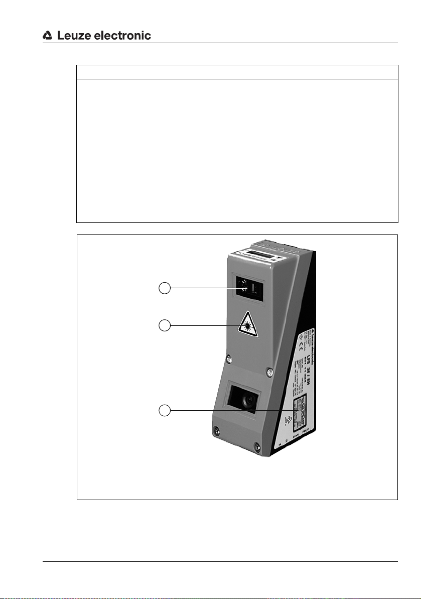
A Laser aperture
B Laser warning sign
C Laser information sign with laser parameters
B
C
A
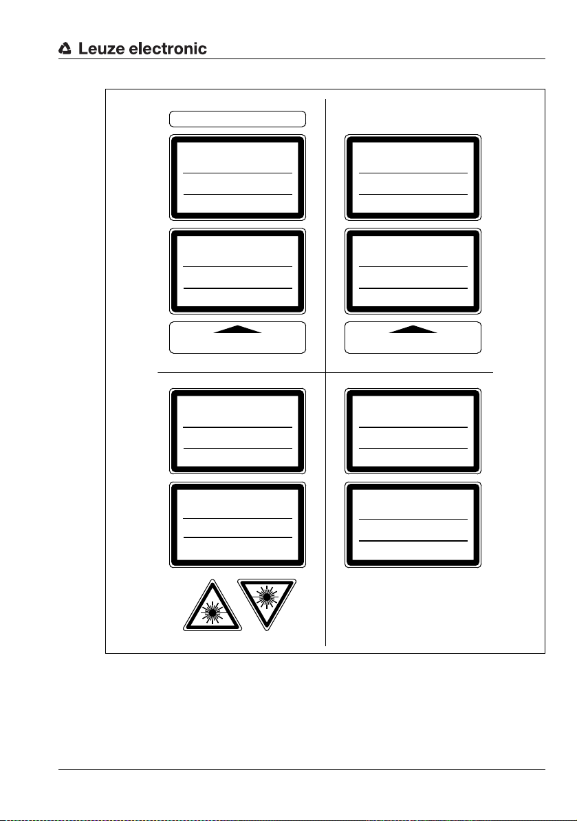
NOTE
Affix laser information and warning signs!
Laser warning and laser information signs are affixed to the device (see Figure 2.1):
In addition, self-adhesive laser warning and information signs (stick-on labels) are supplied
in several languages (see Figure 2.2).
Affix the laser information sheet to the device in the language appropriate for the place
of use.
When using the device in the U.S.A., use the stick-on label with the "Complies with
21 CFR 1040.10" notice.
Affix the laser information and warning signs near the device if no signs are attached
to the device (e.g., because the device is too small) or if the attached laser information
and warning signs are concealed due to the installation position.
Affix the laser information and warning signs so that they are legible without exposing
the reader to the laser radiation of the device or other optical radiation.
Figure 2.1: Laser apertures, laser warning signs
Leuze electronic LES 36 14
TNT 35/7-24V
AVOID EXPOSURE – LASER RADIATION
IS EMITTED FROM THIS APERTURE
EXPOSITION DANGEREUSE – UN RAYONNEMENT
LASER EST ÉMIS PAR CETTE OUVERTURE
LASERSTRAHLUNG
NICHT IN DEN STRAHL BLICKEN
ODER DIREKT MIT OPTISCHEN
INSTRUMENTEN BETRACHTEN
LASER KLASSE 2M
DIN EN 60825-1:2008-05
Max. Leistung (peak):
Impulsdauer:
Wellenlänge:
LASER RADIATION
DO NOT STARE INTO BEAM
OR VIEW DIRECTLY WITH
OPTICAL INSTRUMENTS
CLASS 2M LASER PRODUCT
EN 60825-1:2007
Maximum Output (peak):
Pulse duration:
Wavelenght:
RADIAZIONE LASER
NON FISSARE IL FASCIO AD OCCHIO
NUDO NÉ GUARDARE DIRETTAMENTE
CON STRUMENTI OTTICI
APARRECCHIO LASER DI CLASSE 2M
EN 60825-1:2007
Potenza max. (peak):
Durata dell'impulso:
Lunghezza d'onda:
RAYONNEMENT LASER
NE PAS REGARDER DANS LE FAISCEAU
NI À L`ŒIL NU NI Á L`AIDE D`UN
INSTRUMENT D`OPTIQUE
APPAREIL À LASER DE CLASSE 2M
EN 60825-1:2007
Puissance max. (crête):
Durée d`impulsion:
Longueur d`onde:
RADIACIÓN LÁSER
NO MIRAR FIJAMENTE AL HAZ
NI MIRAR DIRECTAMENTE CON
INSTRUMENTOS ÓPTICOS
PRODUCTO LÁSER DE CLASE 2M
EN 60825-1:2007
Potencia máx. (peak):
Duración del impulso:
Longitud de onda:
RADIAÇÃO LASER
NÃO OLHAR FIXAMENTE O FEIXE
NEM OLHAR DIRECTAMENTE
COM INSTRUMENTOS ÓPTICOS
EQUIPAMENTO LASER CLASSE 2M
EN 60825-1:2007
Potência máx. (peak):
Período de pulso:
Comprimento de onda:
LASER RADIATION
DO NOT STARE INTO BEAM
OR VIEW DIRECTLY WITH
OPTICAL INSTRUMENTS
CLASS 2M LASER PRODUCT
IEC 60825-1:2007
Complies with 21 CFR 1040.10
Maximum Output (peak):
Pulse duration:
Wavelength:
0伊䉏⏘ℶ❐
GB7247.1-2012
㦏⮶戢⒉᧤⽿⋋᧥
厘⑁㖐兼㢅梃
㽱栎
䉏⏘戟⺓
▎䦃展㒥抩扖⏘ⷵ
ⅹ⣷䦃㘴屑䦚⏘㧮
8,7 mW
3 ms
658 nm
8.7 mW
3 ms
658 nm
8,7 mW
3 ms
658 nm
8,7 mW
3 ms
658 nm
8,7 mW
3 ms
658 nm
8,7 mW
3 ms
658 nm
8.7 mW
3 ms
658 nm
8.7 mW
3 ms
658 nm
50111877-02
Safety
Figure 2.2: Laser warning and information signs – supplied stick-on labels
TNT 35/7-24V
Leuze electronic LES 36 15
3 Operating principle
CMOS area
detector
Receiving optics
Laser with expansion optics
The zero point of the coordinate system is the intersection
of optical axis and front edge of
the housing.
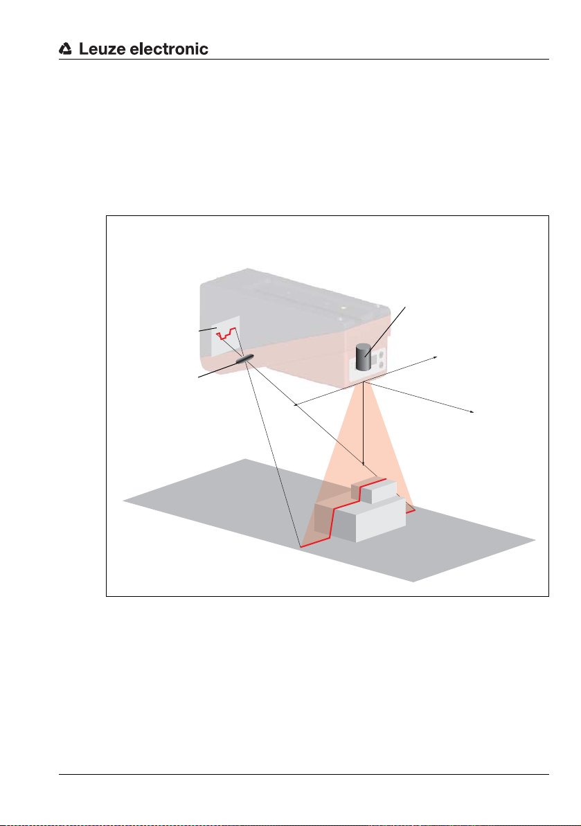
3.1 Generation of 2D profiles
Light section sensors work according to the triangulation principle. Using transmission
optics a laser beam is expanded to a line and aimed at an object. The light remitted by the
object is received by a camera, which consists of receiver optics and the CMOS area
detector.
Operating principle
-X
+X
-Y
Z
Figure 3.1: Light section sensor design
Depending on the distance of the object the laser line is projected to a different position on
the CMOS planar detector as shown in Figure 3.1. By means of this position the distance
of the object can be calculated.
Leuze electronic LES 36 16
TNT 35/7-24V
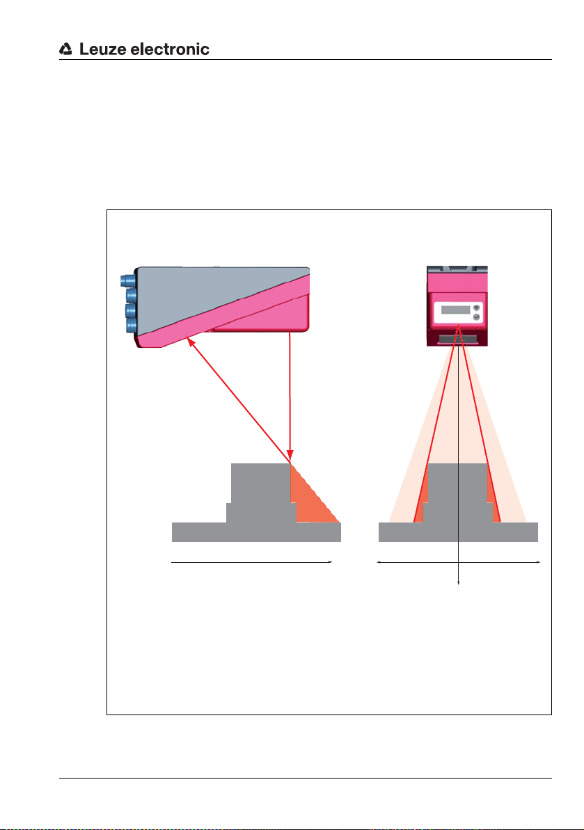
3.2 Limits of light section sensors
Laser occlusionReceiver occlusion
In the red areas the laser does not
strike the object. Thus it is not possible to determine any data here.
The receiver does not "see" any object contours in the
red area because they are obscured by the upper right
edge of the object.
When the object is shifted to the left the object contour will still be detected by the laser but the laser line
does not lie within the receiver's field of view at that
point, and therefore no measurement values can be
detected.
3.2.1 Occlusion
The detection of high and wide objects from just one point poses the particular problem
that depending on the object contour, parts of the object may be obscured by others. This
effect is called occlusion.
The Figure 3.2 illustrates the problem:
Operating principle
Leuze electronic LES 36 17
Figure 3.2: Occlusion
-Y
+X
TNT 35/7-24V
Z
-X
Operating principle
Y
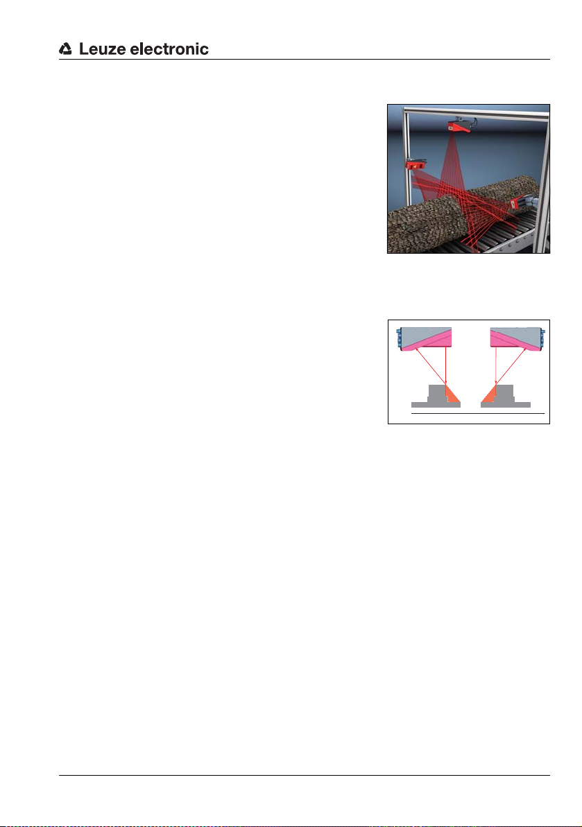
Possible measure against laser occlusion
• Using multiple Light section sensors with rotated
viewing direction. In the application example on
the right you can clearly see that the fields of vision
of the three sensors complement each other and
merge. The first of the sensors is operated as a
master, the two others are cascaded (see "Cascading" on page 24). This reliably prevents mutual
interference of the sensors.
Possible measures against receiver occlusion
• Alignment of the measurement objects so that all profile data to be measured can be
seen by the receiver.
Or:
• Installing a second sensor featuring a viewing
direction rotated by 180° about the z-axis so that
the objects can be viewed from 2 sides.
In the example to the right, the left sensor detects
the profile data on the left side of the product, and
the right sensor the profile data on the right side.
In this situation the second sensor is then cascaded. "Cascading" on page 24.
Leuze electronic LES 36 18
TNT 35/7-24V
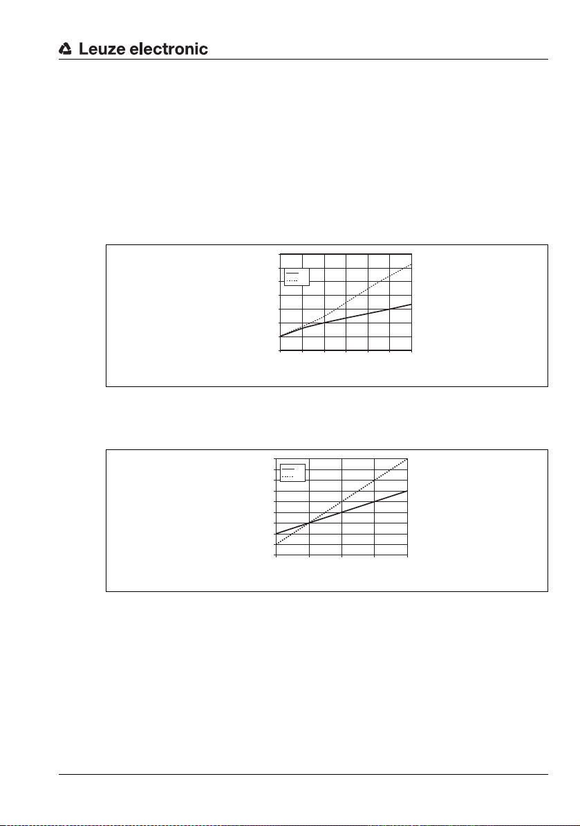
3.2.2 Resolution
0
0,5
1,0
1,5
2,0
2,5
3,0
3,5
200 300 400 500 600 700 800
X
Z
Object distance in Z-direction in mm
Typical resolution in mm
0
0,1
0,2
0,3
0,4
0,5
0,8
0,9
0,6
0,7
200 300 400 500 600
X
Z
Object distance in Z direction [mm]
Typical minimum
object size [mm]
In this context resolution means the smallest possible change in distance of the measurement object, which causes a unique change of the output signal. Resolution is higher in the
short range than in the distant range. Small objects can be recognized better in the short
range.
The length of the laser line in the X-direction is dependent on the distance Z of the measurement object from the sensor . Always the same number of measurement points is measured.
From this it follows that the resolution in X-direction decreases with increasing distance in
Z-direction.
The following illustration shows this relation:
Figure 3.3: Typical resolution LES 36…
The output resolution of the measurement values on the process interface is 1/10mm with
Standard-Connect, 1/100mm with HI-Connect (only with LES 36HI/VC6).
Operating principle
Figure 3.4: Typical minimum object size LES 36HI…
Leuze electronic LES 36 19
TNT 35/7-24V
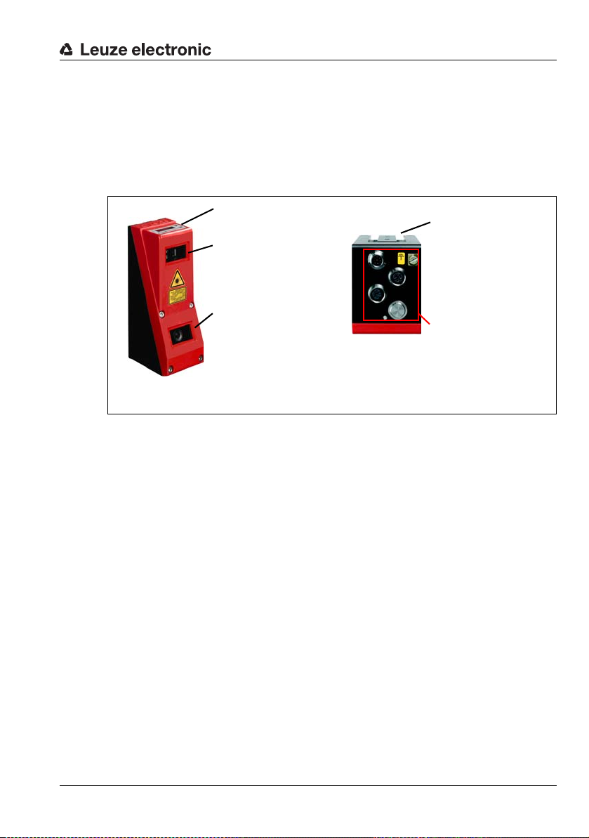
4 Device description
Laser transmitter
Receiver
(CMOS camera)
Display with membrane
keyboard
Electrical connection and
grounding terminal
Groove for dovetail mounting and fastening holes
Note:
The following shows a light section sensor as an example.
An overview of the available types may be found in Chapter 15.1
4.1 Overview of light section sensors
4.1.1 Mechanical design
Figure 4.1: Mechanical design of Leuze light section sensors
Device description
4.1.2 General performance characteristics
• Light section sensor for width, height and position detection
• Measurement time/response time: 10ms
• Measurement range/detection area: 200 … 800mm
• Measurement range/detection area: LES 36…: 200 to 800mm, LES 36HI…: up to
600mm
• Length of laser line: max. 600 mm
• Length of the laser line: LES 36…: max. 600 mm, LES 36HI…: max. 140 mm
• Configuration and transmission of process data via Fast Ethernet
• OLED display with membrane keyboard
• Measurement value display in mm on OLED display as an alignment aid
• Up to 16 inspection tasks
• Compact construction
• Robust design and easy operation
• Activation input, trigger input, cascading output
Leuze electronic LES 36 20
TNT 35/7-24V
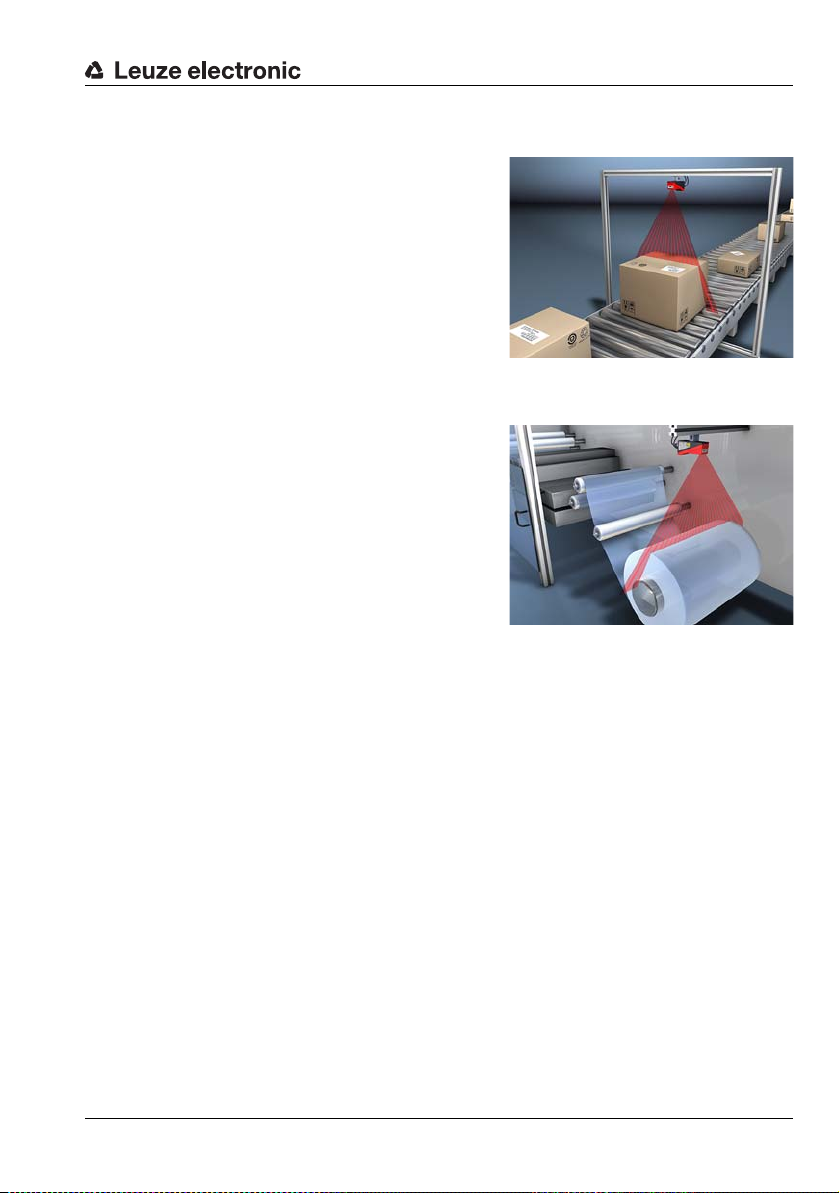
4.1.3 Line Edge Sensor - LES
Width and height measurement of cartons
Determining width and diameter of roll goods
Line edge sensors determine the positions and
dimensions of objects via their edges. The
sensor determines the edge positions in mm
and, from those, calculates the object width and
height. These data are transferred to the
process control. One sensor can be used to
simultaneously detect up to four value pairs of
edges.
Specific performance characteristics
• Configuration software LESsoft
• Data calculation and processing directly
inside the sensor
• Integrated PROFIBUS interface or analog
output
• Up to 4 edge analysis windows with 2
edge-value pairs each
• Up to 8 analysis windows with logic operation option
• Detailed information on measurement
function, analysis windows, detection
functions and sensor state via Ethernet
and PROFIBUS
Device description
Typical areas of application
• Edge and height measurement of web
material products and paper rolls
• Width and height measurement of
cartons
• Edge and height measurement of
stackable materials (e.g. chipboards)
Leuze electronic LES 36 21
TNT 35/7-24V
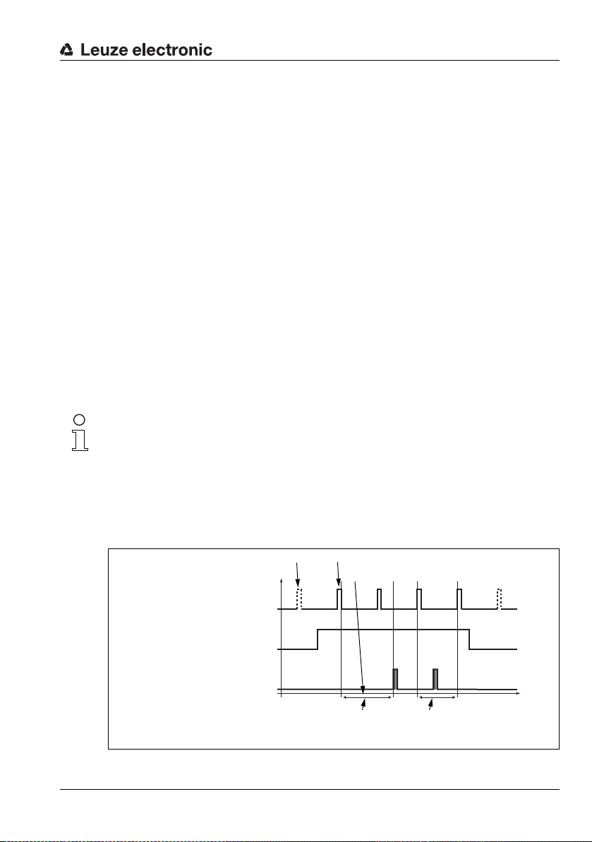
4.2 Operating the sensor
p
t
Laser off
Laser off
Exposing and measuring
Processing and transmitting
Laser
Activation input
Pin 2 at X1
Output
10ms between 2 consecutive
laser pulses in "Free Running"
mode
Axes: p = level, t = time
Approx. 14ms
between laser pulse and
associated data output
4.2.1 Connection to PC / process control
Configuration
For commissioning the Light section sensors are connected to a PC via the Ethernet interface (see "Connection X2 - Ethernet" on page 47) and are then set using the configuration
software supplied LESsoft.
Measurement operation
In measurement operation, the LES 36…/VC6 is connected to the process control via its
analog output, the LES 36…/PB is connected to the process control via PROFIBUS. Alternatively, the LES can be operated via the Ethernet interface on X2, see chapter 10 "Integrating the LES in the process control (Ethernet)". Additional sensor information is then
available.
4.2.2 Activation - laser on/off
The laser and the data transmission can selectively be switched on and off via the activation
input InAct (pin 2 at X1) or via the 'Ethernet Trigger' command. Thus possible glares due
to laser radiation can be prevented during time periods when no measurements are
performed.
Note!
The sensor is delivered ex works with the Activation Input Disregard setting. The
possible activation sources (activation input and Ethernet activation) are ignored - the measurement function of the sensor is enabled.
The activation function can be switched on via the configuration software. To do this, the
Activation Input parameter must be set to Regard. The sensor then only measures if
one of the activation sources is activated. If the sensor is waiting for activation, it displays
!Act
in the display.
Device description
Leuze electronic LES 36 22
Figure 4.2: Activation input signal sequence
TNT 35/7-24V
The Figure 4.2 shows the effect of the activation on laser and measurement value output in
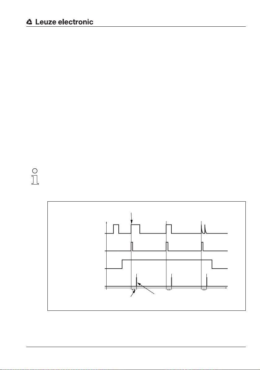
A second trigger
pulse before 10ms
have elapsed has
no effect
Trigger time (rising edge)
Laser
Activation input
Pin 2 at X1
Output
(Ethernet)
Data packets, approx. 1ms
t
fix
Approx. 14ms
Trigger input
Pin 5 at X1
Axes: p = level, t = time
"Free Running" mode.
4.2.3 Triggering - Free Running
The Light section sensors can measure in two modes:
• In "Free Running" operation the Light section sensor determines measurement results
with a frequency of 100Hz and outputs these continuously via the interface X2.
• Alternatively, single measurements can also be carried out. For this purpose, the Light
section sensor requires a trigger signal at the trigger input (pin 5 on X1), a PROFIBUS
trigger or the Ethernet Trigger command in measure mode (see
Chapter 10.3.4"Commands in measure mode" on page 111).
When triggering via pin 5 at X1, note:
- Triggering occurs on the rising edge.
-The trigger pulse must be at least 100μs long.
- Before the next trigger, the trigger cable must be on low-level for at least 1 ms.
- Activation must occur at least 100μs before the trigger edge.
- The shortest possible time interval between two successive trigger edges is 10ms.
Note!
Ex works, the LES is set to Free Running (shown on display:
respond to signals on the trigger input, the operating mode must be set via the LESsoft configuration software to Input Triggered (shown on display:
Device description
fRun
). In order for it to
Trig
).
Leuze electronic LES 36 23
p
Figure 4.3: Trigger input signal sequence
TNT 35/7-24V
t
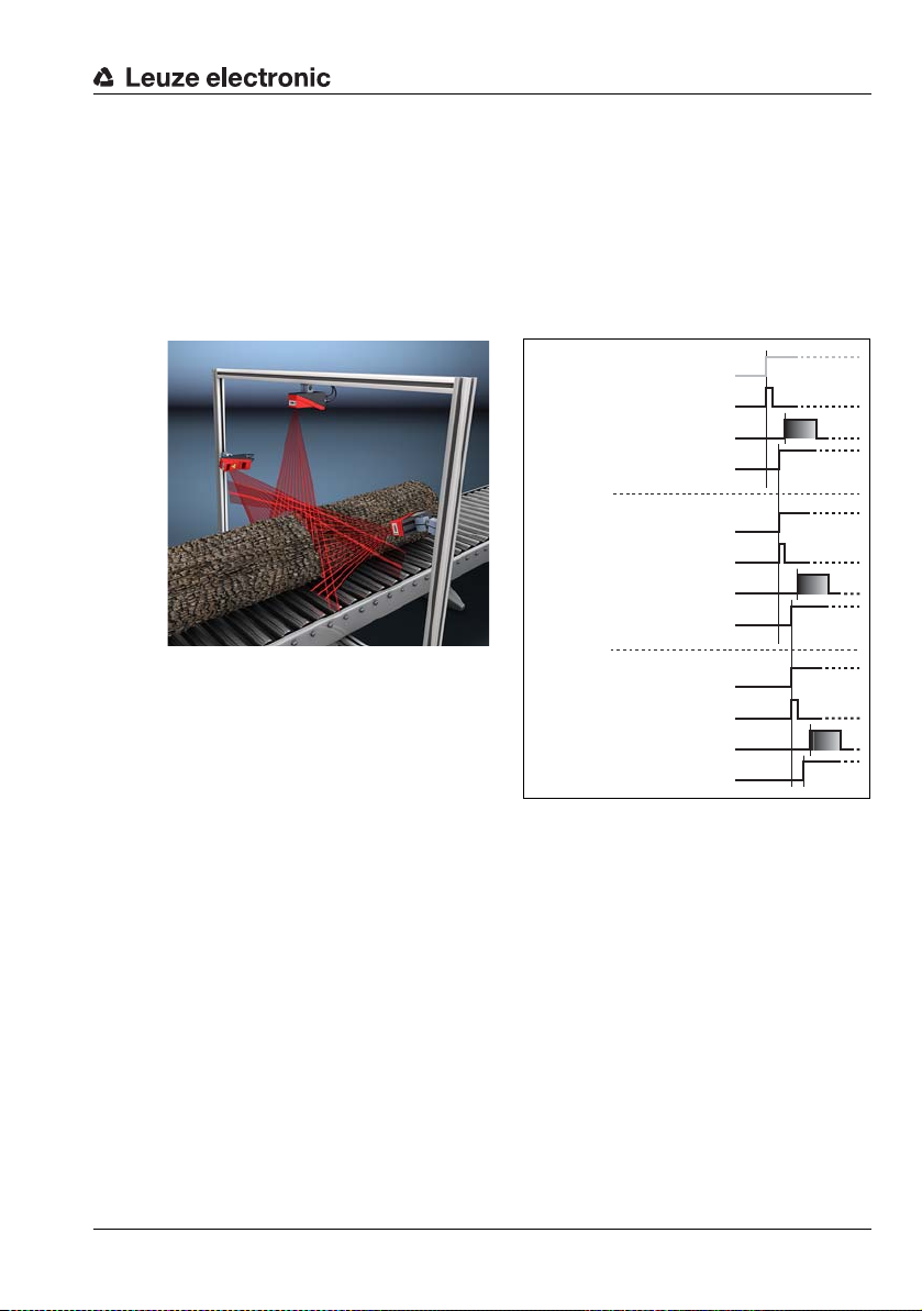
PROFIBUS trigger
Laser
Measurement value output
Trigger input, pin 5 at X1
/ not required
Cascading output,
pin 6 at X1
Sensor 1 / Master
Laser
Measurement value output
Trigger input, pin 5 at X1
Cascading output,
pin 6 at X1
Sensor 2 / 1st slave
Laser
Measurement value output
Trigger input, pin 5 at X1
Cascading output,
pin 6 at X1
Sensor 3 / 2nd slave
Figure 4.4: Signal sequence for cascading
So that a measurement can be triggered on each PROFIBUS cycle, the PROFIBUS trigger
of the LES responds to a change of master output byte uTrigger. The control only needs
to increment the trigger value in order to initiate a new measurement.
The maximum trigger frequency is 100Hz. If triggering occurs during a measurement, the
trigger signal is ignored, as is the case in the Free Running operating mode.
4.2.4 Cascading
Figure 4.5: Cascading application example
If several Light section sensors are operated, there is the risk of mutual interference
if the reflected laser beam of one sensor can
be received by the receiver of another
Leuze electronic LES 36 24
sensor at the time of reading.
This can easily be seen in Figure 4.5. Here
three Light section sensors are used to
determine the log thickness reliably from all
sides.
To prevent mutual interference the Light
section sensors can be operated cascaded: the exposure by the second sensor will be initiated following completion of the exposure by the first sensor. To achieve this, the cascading
output of the first sensor must be connected to the trigger input of the second sensor. Up
to 6 sensors can thus be operated cascaded.
Trigger settings
Se nso r 1, or the m ast er, can be ope rat ed i n th is c ase bot h tr igg ere d as wel l as con tin uou sly.
All other sensors must be operated triggered.
Cascading settings
For all sensors except the last slave, the cascading output must be enabled via configuration
software: Cascading Output: Enable.
Device description
TNT 35/7-24V

Note!
In PROFIBUS operation, cascading only functions as described above via the InTrig and
OutCas inputs/outputs at X1. In this case, the maximum detection rate of 100Hz is achieved.
Make certain, however, that the input data of the PROFIBUS light section sensors are still
transmitted in the same bus cycle; monitor the scan numbers if necessary.
Alternatively, light section sensors with PROFIBUS can be selectively triggered in sequence.
Master output 'uTrigger' of the sensor to be triggered is incremented on each PLC cycle;
the master outputs of the other sensors do not change. The maximum detection rate of
100Hz is not achieved with this process.
If multiple sensors are triggered in a PROFIBUS cycle, mutual interference may occur
between the sensors if they are in the same visual field and the time between updating byte
'uTrigger' is shorter than the maximum exposure time (Exposure Time) of 1.3 ms.
4.3 Measurement functions: LES
With the LES, you can reliably detect objects and measure their edge position, height and
width. Adaptation of the LES to an application is performed using the LESsoft configuration
software. All settings for the application are made there and stored in up to 16 inspection
tasks.
Functional principle of object and edge detection with the LES
The distance profile of the application is determined along the laser line in 376 measurement
points. Rectangular analysis windows, used for object and edge detection, can be defined
in the measurement range.
Object detection:
The number of measurement points is counted in the analysis window (Analysis Window
= AW or Edge Analysis Window = EAW) and compared with two adjustable limits. From this,
the logical state ok or not ok of the analysis window is determined. For unique object detection, it may be necessary to combine multiple analysis windows. For this purpose, the LES
offers the AND combination and inversion of multiple analysis windows. The logic combinations ensure the detection of problematic objects.
Edge detection:
Windows for edge detection are called Edge Analysis Windows (EAW). In an EAW, object
detection can be performed as described above. Also determined in an EAW are the X and
Z coordinates of the first ("left-most") and the last ("right-most") measurement point. By
appropriately selecting the size and position of the EAWs, it is possible to determine coordinates of edge positions. From these, the width and height of an object are calculated. For
robust edge detection, the "Sequent Hits" parameter was introduced. The minimum number
of measurement points set there must occur in succession in the EAW to detect a valid edge.
Outliers or missing measurement points reset the counter.
Device description
TNT 35/7-24V
Leuze electronic LES 36 25

4.3.1 Inspection Task
The LES supports up to 16 individual inspection tasks. Grouped together in an inspection
task are all parameter settings relevant for an application:
• Operation Mode (Free Running, Input Triggered)
• Activation Input (switch laser on and off)
• Cascading Output
• Light Exposure (exposure duration of the laser)
• Field of View (sensor detection range)
• Edit Analysis Windows (size and position of four AWs and four EAWs, object detection
and edge detection parameters)
• Edit Logical Combinations (logic combination of AWs and EAWs, definition of the values that are available via the Profibus)
• Analog Output (analog output definitions)
The selection of the inspection tasks is carried out:
• via the switching inputs of connection X3 (inspection tasks 0-7 only)
•Via PROFIBUS
• via LESsoft (on a PC connected via X2)
• via Ethernet (on a process control connected via X2)
• via the control panel of the sensor beginning with firmware V01.40.
4.3.2 Edge Analysis Window (EAW)
EAWs are used for edge detection; they can also be used for object detection. EAWs are
configured in the LESsoft configuration software (see chapter 9.4 "Parameter settings/
Parameters tab", Figure 9.3). Here, position and size of each EAW are defined. To ensure
stable measurement of edge positions, it is also possible to
• check the edge quality (Sequent Hits, see below),
• count the number of measurement points to be detected in the EAW (a quasi minimum
object size).
An evaluation is carried out only within the active EAWs. Areas outside of the measurement
range and field of view are ignored.
Characteristics of EAWs
• EAWs are rectangular and may overlap freely.
• The coordinates of the left-most measurement point ("leftmost" LX, LZ) and right-most
measurement point ("rightmost" RX, RZ) are determined in each EAW.
• EAWs usually have an absolute position. If the object position varies, an EAW can also
be positioned relative to a found edge position in the previous EAW and thus tracked.
Device description
TNT 35/7-24V
Leuze electronic LES 36 26
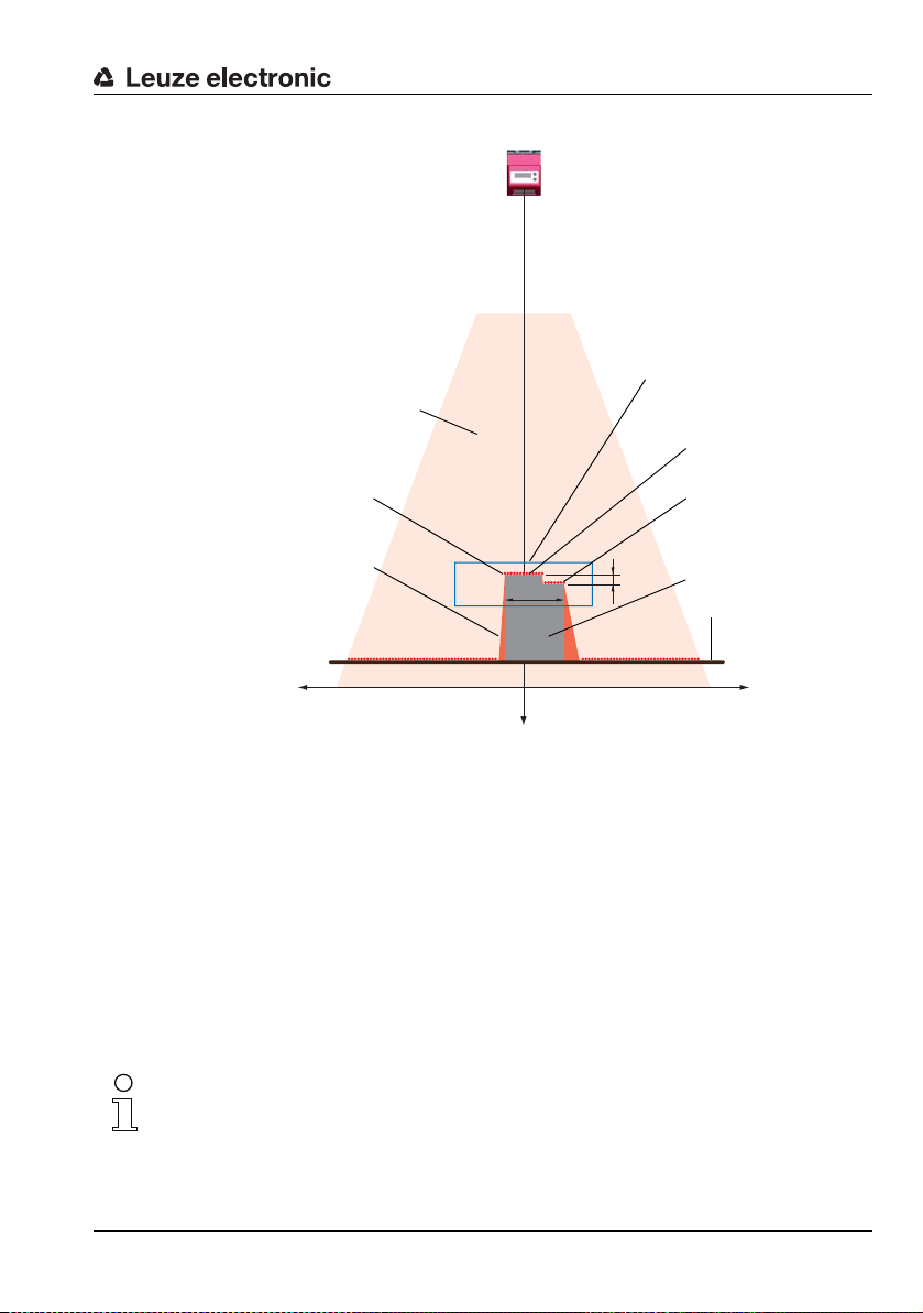
Device description
LES
Measurement range
Object
Measurement points
H = height difference of two edges
W = object width
Edge Analysis Window
EAW
x axis
z axis
No object detection due to
shadowing in the measure-
ment range
Right edge
(coordinates RX, RZ)
Left edge
(coordinates LX, LZ)
Conveyor path
Figure 4.6: Edge detection with EAWs
4.3.3 Definition of EAWs and their analysis results
Edge detection
Edge detection with the LES is possible if the following prerequisites are met:
There are enough successive measurement points in the EAW at both the right and the left
edge. This serves the plausibility of the edge detection.
Edges are only detected if the number of successive measurement points is greater
than or equal to the defined minimum number of measurement points (Sequent Hits).
If there are not enough successive measureme nt poi nts in an EAW , no edg e de tecti on
and no object measurement is possible within this EAW.
Configuration of the edge detection in EAWs is performed with LESsoft (Edit Analysis
Windows -> Edge Detection Definitions).
Note!
If there are not enough successive measurement points on the edges of an EAW, the found
edge positions are shifted away from the edges of the EAW (see Figure 4.7, different right
edge position with different parameters for Sequent Hits).
EAW01
W
H
O1
+X -X
Z
TNT 35/7-24V
Leuze electronic LES 36 27
 Loading...