

Page 1

L300 safety locking devices
1 INFORMATION ON THIS DOCUMENT
1.1 Function
The present operating instructions provide information on installation, connection and
safe use for the following par ts: L300, AC-L300-xCA
1.2 Target audience
The operations described in these operating instructions must be carried out by qualifi ed personnel only, who are fully capable of understanding them, and with the technical qualifi cations required for operating the machines and systems in which the safety
devices are to be installed.
1.3 Area of application
These operating instructions apply exclusively to the devices listed in section Function, and their accessories.
1.4 Original instructions
The German language version is the original set of operating instructions. Versions
provided in other languages are translations of the original instructions.
2 SYMBOLS USED
This symbol indicates any relevant complementary information
Attention: Any failure to observe this warning note can cause damage or mal-
function, including possible loss of the safety function.
3 DESCRIPTION
3.1 Device description
The safety device described in these operating instructions is defi ned as a
coded, type-4 interlock device with guard interlocking and without contact acc. to
EN ISO 14119.
The safety switches with electromagnet and RFID technology, for which these operating instructions apply, are safety devices for the monitoring of gates, safety doors,
enclosures and all protective devices that safeguard the parts of machines with or
without stopping time.
3.2 Intended use of the device
- The device described in these operating instructions is designed to be used on
industrial machines for condition monitoring of movable protective devices.
- The direct sale of this device to the public is prohibited. Installation and use must
be carried out by qualifi ed personnel only.
- The use of the device for purposes other than those specifi ed in these operating
instructions is prohibited.
- Any use other than as expressly specifi ed in this operating manual shall be considered unintended by the manufacturer.
- Also considered unintended use:
a) Using the device after having made structural, technical, or electrical modifi ca-
tions to it;
b) using the product in an area of application other than as described in section
TECHNICAL DATA.
4 MOUNTING INSTRUCTIONS
Attention: Installing a protective device is not suffi cient to ensure personnel
safety or compliance with machine safety standards or directives. Before installing a
protective device, perform a specifi c risk analysis in accordance with the key health
and safety requirements in the Machinery Directive. The manufacturer guarantees
only the safe functioning of the device to which these operating instructions refer, and
not the functional safety of the entire machine or system
4.1 Actuation directions
It is advisable to use actuators with a high coding level so as to make the installation safer and more fl exible. This will render it unnecessary to screen the device, to fi t it
in non-accessible areas or to follow other prescriptions specifi ed by the EN ISO 14119
standard for actuators with low coding level.
4.3 Selection of the operating principle
Attention: The safety switch is available with two operating principles:
1. SLM24 operating principle (quiescent current principle – The locking element is
held in the protective position by spring force): actuator locked if electromagnet
is deactivated.
2. MLM24 operating principle (open circuit current principle – The locking element is
held in the protective position by electromagnetic force): actuator locked if electromagnet is activated.
With the SLM24 operating principle (quiescent current principle), the actuator stays
locked even if the machine is disconnected from the power supply. Therefore, if the
machine has dangerous movements with inertia, inaccessibility to dangerous parts
(actuator locked) is ensured, even in the event of a sudden power failure. On the
contrary, if the machine structure allows a person to enter the danger area with the
whole body and possibly end up being stuck inside the machine, the switch must be
provided with an escape release button, in order to allow the trapped person to get out
even in case of power failure.
With the MLM24 operating principle (open circuit current principle), the actuator stays
locked only when the machine is connected to the power supply. Therefore, before
choosing this operation principle, carefully evaluate all dangers deriving from sudden
power failure with a possibly immediate actuator release.
The choice of SLM24 or MLM24 operating principle must always be made following a
risk analysis of the specifi c application.
In case of machines without inertia, i.e. with dangerous elements being immediately blocked as soon as the safety door is opened, for which a safety device with lock
has been chosen merely to safeguard the production process, the quiescent current
principle or the open circuit current principle can both be used.
4.4 Operating mode selection for activation of safety outputs
Warning: the device is available with three different safety outputs activation
modes:
- Mode 1 (part L300-xxx-Mx1-xx): safety outputs active if actuator is inserted
and locked;
- Mode 2 (part L300-xxx-Mx2-xx): safety outputs active if actuator is inserted;
- Mode 3 (part L300-xxx-Mx3-xx): OS1 safety output active if actuator is inserted
and locked and IS1 is active, OS2 safety output active if actuator is inserted and
IS2 is active.
Mode 1 activates the OS safety outputs when the actuator is both inserted and locked,
so that the actuator cannot be extracted with the safety outputs activated. In mode 1
the device is coded, type 4 (interlock with lock) acc. to EN ISO 14119.
In mode 2, the actuator can be locked/unlocked for special applications while still kept
on the safety chain, typically for specifi c applications without stopping time, when the
risk does not continue after the opening of the protective device. In mode 2 the device
is coded, type 4 (interlock without lock) acc. to EN ISO 14119.
For specifi c applications, mode 3 provides a channel with "mode 1" functionality, and a
channel with "mode 2" functionality. This allows emulation of electromechanical interlock devices with guard interlocking, without complex machine wiring modifi cations.
Using modes 2 and 3 must always follow a risk analysis on the specifi c application,
with particular focus on the function of cascaded mode 3 devices.
The centring symbols on the device and actuator must be aligned with each
other.
4.2 Selection of the actuator type
Attention: The switch is available with two RFID actuator types: one with a high
coding level (part AC-L300-UCA) and one with a low coding level (par t AC-L300SCA). In the case where an actuator with a low coding level has been chosen, ensure
that the additional specifi cations prescribed in section 7.2 of the EN ISO 14119:2013
standard are respected during installation.
Attention: If the chosen actuator has a low level of coding, any other low level
coded actuators present in the same place where the device has been installed must
be segregated and kept under strict control in order to avoid any bypassing of the
safety device. If new low level coded actuators are fi tted, the original low level coded
actuators must be disposed of or rendered inoperable.
1
Subject to modifi cations 2019/03/22 Part no. 50130051
Page 2
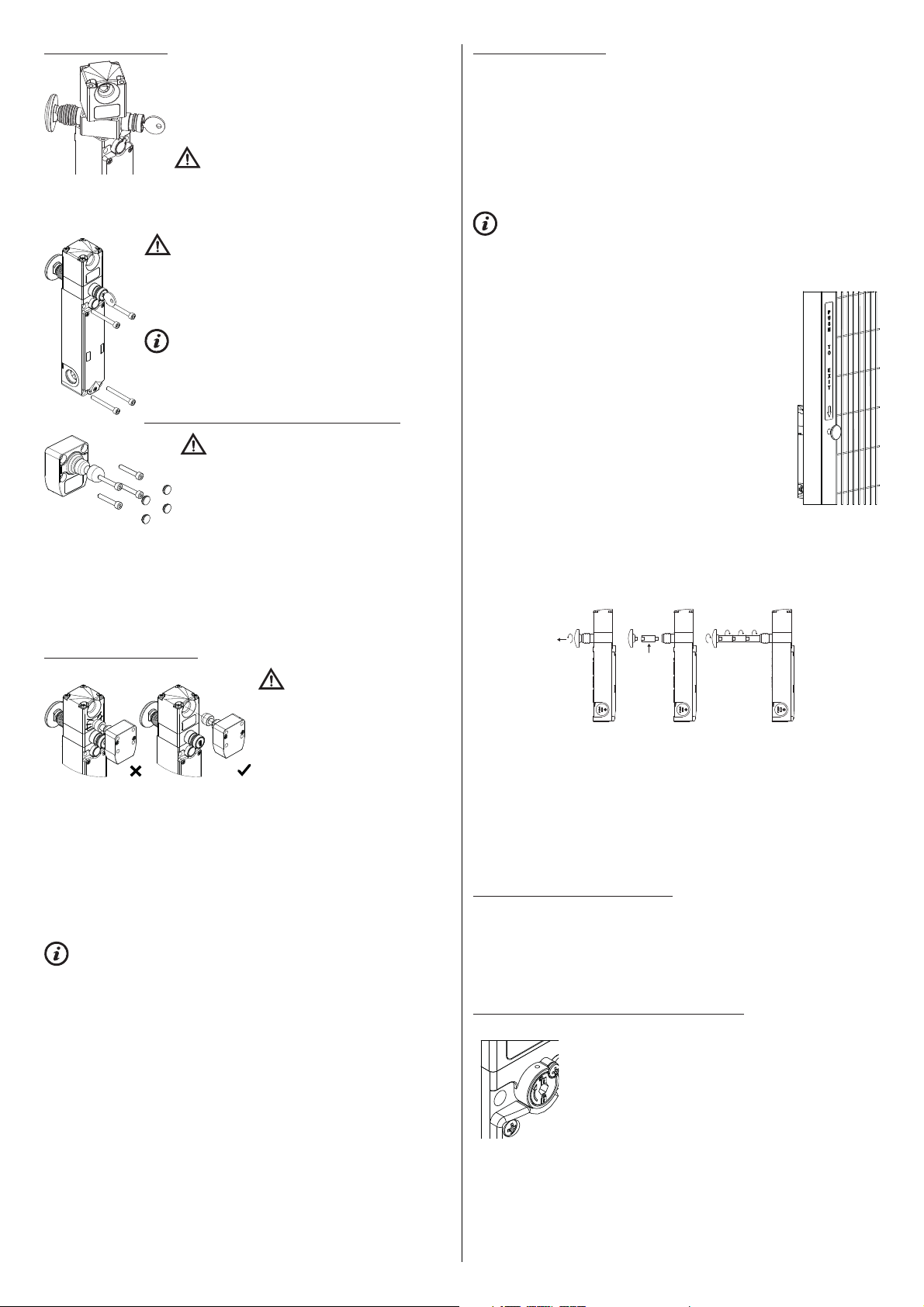
4.5 Mounting the device
Before mounting the device: if necessary, it is possible to
adjust the position of the head and the auxiliary release (if
present) in order to turn the device to the most appropriate
position for the specifi c application. Fully remove the 4
head screws in order to independently turn either the head
or the auxiliary release over an arc of 270°.
Attention: Do not force rotation beyond 270° as this
could cause damage to the device. Once adjustment is
complete, re-tighten the head screws with a torque between 0.8 and 1.2 Nm.
Once the head of the device is in position, you must use the two safety screws supplied, in place of the two original screws, at opposite corners.
Attention: Always fi x the device with 4 M5 screws with
property class 8.8 or higher, and fl at seating heads. Install the
screws with medium thread lock, and a number of threads
engaged equal to or greater than the screw diameter. The device
must never be fi xed with less than 4 screws. Tighten the 4 M5
screws to a torque from 2 to 3 Nm.
It is advisable to install the device in the top part of the door,
in order to prevent any dirt or work residues from getting inside
the hole where the actuator is to be introduced. In order to avoid
device bypassing, it is advisable to fi x the device housing to the
machine frame so that it cannot be removed.
4.6 Mounting the actuator to the protective device
Attention: As required by EN ISO 14119, the actu-
ator must be fi xed immovably to the door frame.
Always fi x the actuator with 4 M5 screws with property class 8.8 or higher, and fl at seating heads. Install
the screws with medium thread lock, and a number of
threads engaged equal to or greater than the screw
diameter. The actuator must never be fi xed with less than
4 screws. Tighten the 4 M5 screws to a torque from 2 to 3 Nm.
After the fi xing operation, it is mandatory to plug the holes of the 4 screws using the
caps supplied. Using the caps is considered a supplementary measure to reduce the
potential of actuator disassembly to a minimum, in accordance with EN ISO 14119.
For correct mounting, other means can also be used, such as rivets, non-removable
one-way security screws or other equivalent mounting systems, as long as they can
ensure adequate mounting.
4.7 Device-actuator alignment
4.8 Escape release button
Some of the device versions are provided with an escape release button in order to
allow any personnel accidentally trapped inside the machine to get out. This button,
complying with the EN ISO 14119 standard, directly acts on the lock mechanism and
immediately releases the actuator regardless of the operating state of the device.
Pressing this button causes:
- In mode 1: immediate deactivation of the OS1, OS2 safety outputs and of the
O4 signal output;
- In mode 2: immediate deactivation of the O4 signal output only;
- In mode 3: immediate deactivation of the OS1 safety output and of the O4 signal
output.
This escape release button unlocks the protective device even if the device is
not powered on.
For correct installation of the escape release button, the following notes must be
observed.
- The escape release button must be clearly visible from inside
the machine.
- Button activation must be easy, immediate and independent
from the machine operating state; for easier recognition of
the button and explanation of its function, stickers are available in various languages.
- For an operator standing outside the machine, the escape
release button must not be within immediate reach when the
safety door is closed.
- To guarantee correct operation and safe resetting, a distance
ranging from 10 to 35 mm must be kept between the wall on
which the button is mounted and the escape release button.
- The release button sliding area is to be kept clean. Any
ingress of dirt or chemical substance can compromise device
operation.
- The personnel concerned must be adequately trained on correct button operation, so as to avoid any improper use (i.e. the button must not
be used as a clothing hook).
- The escape release button must not be used as a machine emergency stop.
For installation on walls thicker than 20 mm, extensions are available for the release
button.
Attention: Although the device is
designed to facilitate alignment between
the device and actuator, excessive misalignment could damage the device.
Periodically check the correct alignment
between the safety device and its
actuator.
Maximum misalignment permitted from
the hole axis for rigid doors: ± 2 mm vertical and horizontal.
The actuator must not hit the outside of the actuator inlet area, and must not be used
as a centering device for the safety door.
In the case of application on swing doors, check that the radius between the axis of the
actuator and the axis of the hinge fi tted on the door is greater than 150 mm.
Do not use a hammer for the adjustments, unscrew the screws and adjust the device
manually, then tighten it in position.
This device is not suitable for applications in which the protective device with the
permanently attached actuator allows misalignments such as the actuator shaft not
entering through the corresponding hole of the device with the door completely closed.
The device is provided with a through hole for inserting the actuator. In the case
where it is used in dusty places, make sure not to obstruct the outlet hole opposite the
inlet hole. This way, any dust which may go inside the hole will always be allowed to
come out of the opposite side.
For correct installation of the extensions, the following notes must be observed:
- Do not exceed an overall length of 500 mm between the release button and the
device;
- Always use medium screw locking adhesive on every screw connection between
button, extensions, and safety device;
- Avoid twisting or bending the release button, if necessary use an appropriate
sliding guide (pipe or bush) when the button and its extensions exceed a length
of 100 mm;
- Tightening torque for button and extensions from 4 to 5 Nm.
4.9 Auxiliary release with a tool or lock
Some of the device versions are provided with an auxiliary release in order to allow
easy installation (release with a screwdriver) or to permit opening for authorized
personnel only (lock release). Both these mechanical release devices act inside the
safety device like the escape release button previously described. Therefore they also
unlock the protective device in case of power failure. These auxiliary release may
only be operated by qualifi ed personnel who has received adequate training on the
dangers deriving from their use.
4.9.1 How to use the auxiliary release with a screwdriver
- Unscrew the locking screw with a PH1 cross-head screwdriver
- Turn the hexagon socket clockwise by 180°
- Do not force the hexagon socket beyond 180°
- To avoid any improper use of the auxiliary release with a tool, it
is advisable to seal the device through the appropriate hole found
in the upper part, or to seal the screw cross head with a few drops
of paint.
- After each actuation, it is advisable to reseal the device.
2
Page 3
4.9.2 How to use the auxiliary release with lock
1
1
2
6
1
2
6
- Open the protection cap.
- Insert the key supplied with the device and turn clockwise by 180°.
- Do not force the key beyond 180°.
- Each time the key is extracted, close the rubber cap.
- The release key must only be made available to the
machine maintenance engineer and kept in a secluded
place.
- The release key must not be made available to the
machine operator.
- Never leave the release key inserted in the device during normal machine operation.
For particular applications, versions are available without any auxiliary release
device.
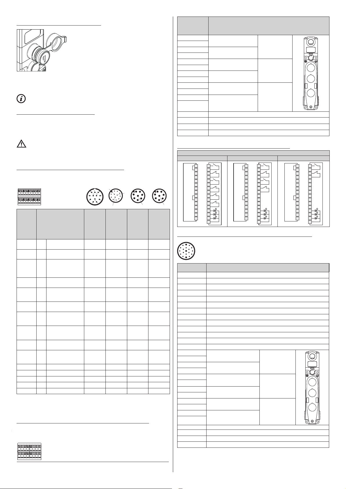
4.10 Electrical connections of the device
All L300 device models are supplied with a wire bridge between IE1 (pin 8) and IE2
(pin 9) of the internal terminal strip. This means that they are preset for "single-channel
activation of the electromagnets" via I4 (pin 3 of the internal terminal strip). If this wire
bridge is removed, electromagnet activation via IE1 and IE2 is mandatory.
Attention: The device is fi tted with OSSD type semiconductor electronic safety
outputs. These outputs behave differently from electromechanical contacts. Use and
installation of a safety device with semiconductor outputs is only permitted if all characteristics of this particular type of outputs are known in detail.
4.10.1 Internal terminal strip for devices with standard cover
To open the device cover, use a PH2 cross-head screwdriver, and tighten the screws
to a torque between 0.8 and 1.2 Nm.
1
9
0
8
4
5
11
M12 con-
nector,
12-pin
12
7
6
3
M12 con-
nector,
Stand-
alone
connection
2345678
1
10
11 121314
Internal
terminal
switches
Attention: terminals 7, 17, 18, of the internal terminal strip must not be used.
(a) Only L300-xxx-M5x version available.
(b) For article L300-xxx-M6x, the output signals the error state of the device.
(c) In single-channel actuation mode, inputs IE1 and IE2 must be short-circuited.
(d) For article L300-xxx-M7x, the O3 and O4 signal outputs have negative function logic (active
signal low).
9
15 161718
strip
for
1
2
3
4
5
6
8
9
10
11
12
13
14
15
16
Connection
Power supply
A2
B2
I4
O3
O4
I3
IE1
IE2
A1
B1
input 0 V
Auxiliary power supply
output 0 V
Input for activation of
the electromagnet in
single-channel opera-
tion (c)
Signal output for
inserted actuator (d)
Signal output for
inserted and locked
actuator (b) (d)
Actuator programming
input / reset
Input for activation of
the electromagnet in
two-channel operation
Input for activation of
the electromagnet in
two-channel operation
Power supply input
+24 VDC
Auxiliary power supply
output
+24 VDC, max. 8 A
IS1 Safety input 2 2 / 2
IS2 Safety input 6 6 / 6
I5 EDM input (a) 11 11 / /
OS1 Safety output 4 4 4 4
OS2 Safety output 7 7 7 7
M23 con-
2
3
nector,
12-pin
3333
3333
10 10 8 8
552 /
9955
886 /
10 10 / /
12 12 / /
1111
1111
4.10.2 Internal terminal strip for devices with integrated command devices
The switch can be supplied with a cover equipped with one to three integrated command devices. The following table illustrates the standard connections for these
devices. Other confi gurations are available on request.
19
20 212223
24 25
26
27
28 29 3031
32 33
34
4
8-pin
7
5
8
7
3
4
8
M12 con-
nector
8-pin
Series
connection
with Y-con-
nectors
Internal terminal
strip for inte-
grated command
devices (a)
19
20
21
22
23
24
25
26
27
28
29
30
31
32
33
34
Contact 1
Contact 2
Contact 1
Contact 2
Contact 1
Contact 2
Power supply input +24 VDC / device 1 LED
Power supply input +24 VDC / device 2 LED
Power supply input +24 VDC / device 3 LED
Power supply input 0 V / LED
Connection
Device 1
Device 2
Device 3
(a) terminals 1-16, see section 4.10.1
4.10.3 Switch with integrated command devices and cable inlet
3 command devices 2 command devices 1 command device
19
1
A2
B2
I4
O3
O4
I3
IE1
IE2
A1
5
B1
IS1
IS2
I5
OS1
OS2
20
2
21
3
22
4
23
5
24
6
25
8
26
9
27
10
28
11
29
12
30
13
31
14
32
15
33
16
34
L300-Bx-xxxC3
1
A2
2
B2
3
I4
4
O3
5
O4
6
I3
8
IE1
IE2
9
A1
10
B1
11
IS1
12
IS2
13
I5
14
OS1
15
OS2
16
19
20
21
22
23
24
25
26
27
28
29
30
31
32
33
34
1
A2
2
B2
3
I4
4
O3
5
O4
6
I3
8
IE1
IE2
9
A1
10
B1
11
IS1
12
IS2
13
I5
14
OS1
15
OS2
16
4.10.4 Switch with integrated command devices and M23 connector, 19-pin
12
1
11
2
18
10
13
17
9
3
19
141516
8
4
7
5
6
M23 connector,
19-pin
19
19
1
8
9
7
6
6
2
3
12
4
5
17
6
/
/
15
6
/
/
10
11
13
14
18
16
/
19
Attention: terminals 7, 17, 18, of the internal terminal strip must not be used.
(a) Only L300-xxx-M5x version available.
(b) For article L300-xxx-M6x, the output signals the error state of the device.
(c) IE1 and IE2 are not available for this connector version.
(d) For article L300-xxx-M7x, the O3 and O4 signal outputs have negative function logic (active
A2 Power supply input 0 V
B2 Auxiliary power supply input 0 V
I4 Input for activation of electromagnet (c)
O3 Signal output for inserted actuator (d)
O4 Signal output for inserted and locked actuator (b) (d)
I3 Programming input for teaching in a new code
A1 Power supply input +24 VDC
B1 Auxiliary power supply output +24 VDC, max. 8 A
IS1 Safety input
IS2 Safety input
I5 EDM input (a)
OS1 Safety output
OS2 Safety output
Contact 1
Contact 2
Contact 1
Contact 2
Contact 1
Contact 2
Power supply input +24 VDC / device 1 LED
Power supply input +24 VDC / device 2 LED
Power supply input +24 VDC / device 3 LED
Power supply input 0 V / LED
Connection
Device 1
Devices 2
Devices 3
3
1
2
3
19
20
21
22
23
24
25
26
27
28
29
30
31
32
33
34
1
2
3
Page 4

signal low).
L300-Bx-xxxM23B19
3 command devices 2 command devices 1 command device
6
19
A2
B2
I4
O3
O4
I3
17
19
1
8
6
9
15
7
6
6
14
2
13
3
11
12
10
4
18
5
16
19
A2
B2
I4
O3
O4
I3
6
1
19
17
19
1
8
6
9
15
7
6
6
2
3
12
4
18
5
16
19
A2
B2
I4
O3
O4
I3
6
19
17
19
1
8
9
7
6
6
2
3
12
4
18
5
19
4.11 RFID sensor switching points
The RFID sensor on the device recognizes the actuator when placed in front of it.
Within this fi eld, the O3 signal output and the ACT LED are activated to signal the
"protective device closed" state. In this state, it is possible to obtain protective device
locking via the I4 (or IE1/IE2) input. After the locking operation, the LOCK LED and
the O4 output are activated; at the same time the RFID sensor increases its switching
distance, so as to ensure that no vibrations or impacts occurring with the protective
device locked may cause the OS1, OS2 and O4 outputs to open accidentally. If the I4
input (or IE1/IE2) is activated or deactivated, without the actuator being present, the
device does not carry out any locking and does not activate any of the OS1, OS2, or
O4 outputs. In order to open the protection, I4 input (or IE1/IE2) must be used; with
the protection released, the O4 output will be deactivated and the LOCK LED will be
switched off. At this point, the RFID sensor will bring its inter vention distance back to
the initial values and, after the protective device has been opened, the O3 output and
the ACT LED will be deactivated.
5 OPERATION
5.1 Access monitoring
These safety devices alone are not suffi cient to protect any operators or maintenance
engineers in the event of fully entering the danger zone, since any unintentional closing of a safety door behind them could allow the machine to be restarted. In case the
machine restarting control is entirely entrusted to these switches, a device must be
provided to avoid that risk, such as a lock-out/tag-out system which stops the machine
from being restarted. A specifi cally designed lock-out/tag-out device is available as
an accessory for this safety switch, which prevents any unintentional machine start
up with the operator still inside (AC-L300-SH-LCK1-A3-P safety door handle; part
number 50133287).
5.2 Defi nitions
Switch operating states:
• OFF: the device is off, not powered.
• POWER ON: status immediately following switching on, when the device carries
out internal tests.
• RUN: status in which the device works normally.
• ERROR: error status in which the safety outputs are deactivated. Indicates that a
fault is present inside or outside the device, such as:
- short circuit between safety outputs (OS1 and OS2),
- short circuit between a safety output and ground,
- short circuit between a safety output and the supply voltage,
- excessive misalignment between a switch and a locked actuator,
- excess of maximum holding force with failure of the relating device in locked
condition,
- excess of maximum or minimum ambient temperature admitted,
- internal error.
• The safety functions are defi ned as follows.
Mode 1: 1.1 The OS safety outputs must be deactivated when the actuator is
Mode 2: 2.1 The OS safety outputs must be deactivated when the actuator is
Mode 3: 3.1 The OS1 safety output must be deactivated when the actuator is
detected as unlocked.
1.2 The OS safety outputs must be deactivated when the actuator is
no longer detected.
1.3 The OS safety outputs must be deactivated when at least one
safety input (IS1 or IS2) is not active.
no longer detected.
2.2 The OS safety outputs must be deactivated when at least one
safety input (IS1 or IS2) is not active.
detected as unlocked.
3.2 The OS2 safety output must be deactivated when the actuator is
no longer detected.
3.3 The OS1 safety output must be deactivated when the IS1 safety
input is not active.
3.4 The OS2 safety output must be deactivated when the IS2 safety
input is not active.
In all operating modes, the device must keep the protective device closed and locked
when the electromagnet is active (MLM24 operating principle) or inactive (SLM24
operating principle) and the applied force is lower than the declared FZh value.
• External Device Monitoring (EDM) is a function (available depending on the device
model) that allows the device to monitor the state of external contactors. Activation
and deactivation of external contactors must follow the state of the L300 switch
safety outputs within a maximum delay.
5.3 Operation description
Note: The following operation description refers to a device with safety outputs active
when the protection is closed and locked (mode 1).
A device with safety outputs activated by closing the protective device (mode 2) differs
from the above operating mode for the fact that the safety outputs OS1 and OS2 are
activated without the f4 function verifying the protective device locking.
Mode 3 differs, in that OS1 is activated when the protective device is closed and
locked, and OS2 with protective device closed.
After being correctly installed by following the present instructions, the safety device
can be supplied with power. The block diagram below shows 5 logically linked
sub-functions of the safety device.
In the initial "POWER ON" status, function f0 of the
CODE
EDM
I5
IN
IS1
IS2
f2
f5
f4
f1
PWR
f3
f0
A2A1
safety device carries out an internal self-diagnosis
which, if successfully completed, brings the device to
the "RUN" operating state. If the test is not passed
ACT
due to an internal fault, the device enters the
O3
"ERROR" status.
LOCK
O4
On EDM versions, at power on, the EDM signal is
checked and it must be active within 500 ms from
OUT
device startup. If the EDM signal is not present after
OS1
this time span has elapsed, function f5 puts the
OS2
device in the "FAULT" operating state.
The "RUN" operating state indicates normal opera-
tion: Function f1 evaluates the state of the IS1 and
IS2 inputs, while at the same time function f2 checks that the actuator is present, and
function f4 checks that the actuator has been locked.
In the EDM versions the f5 function verifi es the coherence of the EDM signal during
operating state changes and when the safety outputs are off.
When these three conditions occur, function f3 of the device activates the OS1 and
OS2 safety outputs.
The IS1 and IS2 inputs of the device are usually actuated simultaneously and therefore they are monitored, in terms of their state and their coherence. The device deactivates the safety outputs and signals the state of non-coherent inputs by means of
IN LED green/orange fl ashing, in the case where only one of the two inputs is deactivated. In order to reactivate the safety outputs, both inputs have to be deactivated and
subsequently reactivated.
During the RUN state, function f0 cyclically carries out internal tests in order to detect
any faults. Any internal error being detected brings the device to the "ERROR" state
(PWR LED with red fi xed light), which immediately deactivates the safety outputs.
The "ERROR" state can be reached even in the case of short circuits occurring
between the safety outputs (OS1 and OS2) or a short circuit of an output towards
earth or towards the power supply. Also in this case, function f3 deactivates the safety
outputs, and the error status is indicated by the OUT LED red fl ashing light.
The O3 signal output is activated during the "RUN" state when the actuator is inserted
in the device, regardless of the state of the IS1and IS2 inputs. The state of this output
is displayed by means of the ACT LED.
The O4 signal output is activated during the "RUN" state when the actuator has been
inserted and locked inside the device, regardless of the state of the IS1and IS2 inputs.
The state of this output is displayed by means of the LOCK LED.
The actuator lock or unlock command is transmitted to the device through the I4 input.
I3 input has different functions, depending on the state of the L300:
- Actuator inserted but not locked: I3 activates the "Teaching an actuator" function
(see section 5.4).
- L300 in error state: I3 activates the reset function (see section 5.5)
- Actuator inserted and locked: I3 without function.
5.4 Actuator replacement
Attention: The machine manufacturer must restrict access to the sensor pro-
gramming mode to authorized personnel only.
4
Page 5

The I3 input can be used, at all times, to replace the coded actuator with a second
actuator. By activating this input, the device gets ready for programming mode with the
IN LED orange light fl ashing, it deactivates all the OS1, OS2, O3 and O4 outputs and
then releases the actuator. Keep the input active while inserting the second actuator.
Acquisition of the second actuator is confi rmed by the IN LED switching off and by
four fl ashes of the ACT LED. At this point, it is possible to deactivate the I3 input. The
device will automatically be brought to the restart state and the fi rst actuator is no
longer detected.
The second actuator will have to be adequately fi xed to the protective device as
explained in section MOUNTING INSTRUCTIONS.
This operation must not be carried out as a repair or maintenance operation. In the
case where the device stops working correctly, replace the entire device and not just
the actuator.
5.5 Reset input
The following error states due to a device external failure can be reset using the I3
input:
- a short circuit or overload of safety outputs (OS1 and OS2),
- short circuit between a safety output and the supply voltage,
- excessive misalignment between a safety device and a locked actuator.
5.6 Series connection with safety modules
It is possible to install several devices in cascade connection up to a maximum number
of 32 units, while maintaining safety category 4 / PL e according to EN ISO 13849-1
and SIL CL 3 integrity level according to EN 62061.
Check that the PFHd and MTTFd values of the system comprising the series connection of devices and the whole safety circuit meet the SIL/PL requirements prescribed
for the application.
Application example with single-channel
locking control function
AC-L300-xCA•
AC-L300-xCA•
AC-L300-xCA•
+ Vcc
IS1 IS2
I4
L300
OS1 OS2
IS1 IS2
I4
L300
OS1 OS2
IS1 IS2
I4
L300
OS1 OS2
Ixx Ixx Ox
MSI 400
Device in mode 1
Locking device detection function (protective
device interlocked): 2 channels / category 4 /
up to SIL 3 / PL e
Locking control function:
1 channel / category 2 / up to SIL 2 / PL d
Device in mode 2
Interlock detection function (protective device
closed): 2 channels / category 4 / up to SIL 3
/ PL e
Locking control function:
1 channel / category 2 / up to SIL 2 / PL d
Application example with two-channel lock-
ing control function
IS1 IS2
L300
OS1 OS2
IS1 IS2
L300
OS1 OS2
IS1 IS2
L300
OS1 OS2
Ixx Ixx
+ Vcc
MSI 400
AC-L300-xCA•
AC-L300-xCA•
AC-L300-xCA•
IE1
IE2
IE1
IE2
IE1
IE2
OS1 OS2
Device in mode 1
Locking device detection function (protective
device interlocked): 2 channels / category 4 /
up to SIL 3 / PL e
Locking control function:
2 channels / category 4 / up to SIL 3 / PL e
Device in mode 2
Interlock detection function (protective device
closed): 2 channels / category 4 / up to SIL 3
/ PL e
Locking control function:
2 channels / category 4 / up to SIL 3 / PL e
When connecting the devices in series as described above, observe the following:
- Connect the inputs of the fi rst device in the chain to the power supply.
- The OS1 and OS2 safety outputs of the last device in the chain must be connected to the safety circuit of the machine.
- Where a safety module is used, check that the properties of OS1/OS2 safety outputs are compatible with the safety module inputs (see section INTERFACING).
- Observe the limits of the output cable stray capacitance, as specifi ed in the
electrical data (see section TECHNICAL DATA).
- Check that the cascade response time fulfi lls the requirements of the safety
function to be obtained.
- The chain response time must be calculated taking into account the response
time of each device.
- When using Y-cables for series connection, special attention must be paid to
the fl owing currents, cable cross-sections and cable lengths in order to ensure
that the supply voltage of the components at the end of the series connection is
within the specifi ed electrical limits of the L300 during operation.
5.7 Operating states
PWR
IN
OUT
ACT
LED
LED
LED
LED
LOCK
LED
OOOOOOOFFDevice switched off.
Flashing
Flashing
Flashing
Flashing
green/
red
green/
red
green/
red
green/
red
Flashing
green/
red
Green O O
Green Green
Green Green /
orange,
fl ashing
O
Device
a
EDM
status
Flashing
POWER ONInternal tests at switching on.
green/
red
Green RUN Safety inputs of the device
Description
not active.
RUN Activation of safety inputs.
RUN Noncoherent safety inputs.
Recommended action: check
input signal activation and/or
wiring of inputs.
PWR
Green
Green
Green
Green Green Green Green Green O RUN Mode 1: activation of IS1 and
Green Green Green Green
Green Orange Orange Green Green O RUN Mode 3: Actuator present,
Green Green Orange Green O O RUN Mode 3: Actuator present,
Green
Green O O Red,
Red,
fl ashing
Green
Green Green Green Green Green O RUN EDM signal not active (exter-
Green O O O O Red,
IN
OUT
ACT
LED
LED
LED
LED
LOCK
LED
Green RUN Actuator in safe area. O3
Red,
fl ashing
Green Green O RUN Actuator in safe area and
Red,
fl ashing
fl ashing
O O ERROR Actuator detection error.
RedOOOOOERRORInternal error. Recommended
OOOOOERRORTemperature error: outside
O Green RUN EDM signal active (external
Device
a
EDM
status
Description
signal output active.
RUN Noncoherent inputs IE1
and IE2 for electromagnet
activation.
Recommended action: check
input signal activation and/or
wiring of inputs.
locked, O3 and O4 outputs
active.
IS2 safety inputs. Actuator
in safe area and locked. O3,
O4, OS1 and OS2 outputs
active.
O RUN Mode 2: activation of IS1 and
IS2 safety inputs. Actuator
in safe area. O3, OS1, and
OS2 outputs active.
protective device closed
and locked, IS1 active, IS2
not active, OS1 active, OS2
not active
protective device closed
and not locked, IS1 and IS2
active, OS1 not active, OS2
active
ERROR Error on safety outputs.
Recommended action:
check for any short circuits
between the outputs, outputs
and ground or outputs and
power supply, then restar t
the device.
Check for physical integrity
of the device. In case of
damage, please replace the
entire device. If undamaged,
realign the actuator and
restart the device.
action: restart the device. If
the fault persists, replace
the device.
the permissible range
a
relay off)
a
ERROR Error in EDM function
fl ashing
nal relay on)
a
O = off = indifferent (a) = only available with the L300-xx-M5xx version
5.8 Interfacing
Connection to the MSI-SR-LC21
safety module
Input confi guration with monitored start
+
A1
S21 S22
+
A1
IS1
OS1
S12
MSI-SR-LC21
L300
-
IS2
A2
OS2
S33
S31
S34
A2
-
Connection to the MSI 400 safety
The connections vary according to the pro-
+
A1
module
gram of the safety module
-
A2
IS2
IS1
L300
OS2
OS1
Ixx
Ixx
MSI 400
+
IS2
A1
IS1
L300
OS2
OS1
IxxIxx
EDM connection
Attention: if all OS safety outputs are connected directly to a safety contactor, we recommend using fast-switching diodes connected in
parallel to the contactor coils.
+
A1
I5
L300-xx-M5xx
KM1
-
A2
OS2
OS1
KM2
-
-
-
A2
5
Page 6

6 INSTRUCTIONS FOR PROPER USE
6.1 Installation
Attention: The installation must exclusively be carried out by qualifi ed personnel.
The OS1 and OS2 safety outputs of the device must be connected to the safety circuit
of the machine. The O3 and O4 signal outputs are not safety outputs and cannot be
used individually in a safety circuit to determine the "protection closed" state.
- Do not stress the device with bending and torsion.
- Do not modify the device for any reason whatsoever.
- Do not exceed the tightening torques specifi ed in the present operating
instructions.
- The device carries out a personnel protection function. Any inadequate installation or tampering can cause people serious injuries and even death as well as
property damage and fi nancial losses.
- These devices must not be bypassed, removed, turned or disabled in any other
way.
- If the machine where the device is installed is used for a purpose other than the
intended use, the device may not provide effi cient personnel protection.
- The safety category of the system (according to EN ISO 13849-1), including
the safety device, also depends on the external devices connected to it and
their type.
- Before installation, make sure the device is not damaged in any part.
- Before installation, ensure that the connection cables are not powered.
- Avoid excessive bending of connection cables in order to prevent any short circuits or power failures.
- Do not paint or varnish the device.
- Do not drill the device.
- Do not use the device as a support or rest for other structures, such as cable
ducts or sliding guides.
- Before commissioning, make sure that the entire machine (or system) complies
with all applicable standards and EMC directive requirements.
- The device fi tting surface must always be smooth and clean.
- Should the installer be unable to fully understand the documents, the product
must not be installed and the necessary assistance may be requested from the
manufacturer (see section SUPPORT).
- Check for correct switching of the outputs and correct operation of the system
comprising the device and associated safety module before commissioning the
machine and in regular intervals.
- In proximity of the device do not carry out arc welding, plasma welding, or any
other process that may generate electromagnetic fi elds of intensity higher than
the limits prescribed by the standards, even when the device is off. Where welding operations are to be carried out in the proximity of the previously installed
device, it must fi rst be moved away from the work area.
- When the device is installed on a mobile door frame and the actuator is installed
on a mobile door, check that the device isn't damaged by simultaneous opening
of the frame and the door.
- After installation, check for correct operation of the auxiliary release (if present)
and the escape release button.
- Always attach these operating instructions to the manual of the machine in which
the device is installed.
- These operating instructions must be kept available for consultation at any time
and for the whole period of use of the device.
6.2 Not to be used in the following areas
- An environment where continuous temperature changes cause condensation
inside the device.
- An environment where the application causes the device to be subject to strong
impact or vibration.
- An environment where explosive or fl ammable gases are present.
- An environment where the device may become coated with ice.
- An environment containing strongly aggressive chemicals, where the products
coming into contact with the device may impair its physical or functional integrity.
6.3 Mechanical limit stop
Attention: The door must always be provided with an independent mechanical
limit stop at the end position.
Do not use the device as mechanical limit stop for the door.
6.4 Maintenance and function tests
Attention: Do not disassemble or try to repair the device. In case of any malfunc-
tion or fault, replace the entire device.
Attention: In case of any damage or wear, the entire device with actuator must
be replaced. Correct operation cannot be guaranteed when the device is deformed
or damaged.
- The device installer is responsible for establishing the sequence of function tests
to which the installed device is to be subjected to before machine commissioning
and during maintenance intervals.
- The testing sequence can vary according to machine complexity and circuit
diagram, therefore the functional test sequence detailed below is to be considered as minimal and not exhaustive.
- Perform the following sequence of checks before the machine is commissioned
and at least once a year (or after a prolonged shutdown):
1. Lock the protective device and start the machine. It must be impossible for the
protective device to be opened.
2. Try to start the machine while the protective device is open. The machine must
not start.
3. Check correct actuator to device alignment. If the actuator insertion opening is
worn, replace the entire device and actuator assembly.
4. When the escape release button (if present) is pressed, the protective device must
open freely and the machine must not start. Each time the escape release button
is activated, the machine must stop and the safety door must open immediately.
The escape release button must slide freely and be tightly screwed in. The signs
placed inside the machine, indicating the function of the escape release button (if
fi tted), must be intact, clean and clearly readable.
5. When the auxiliary release (if present) is activated, the protective device must
open freely and the machine must not start (for devices with mode 3, check that
the machine shows the expected behavior)
6. If the protective device is closed but not locked, it must not be possible for the
machine to start (not applicable in mode 2, for devices with mode 3, check that the
machine shows the expected behavior).
7. All external parts must be undamaged.
8. If the device is damaged, replace it completely.
9. The actuator must be securely locked to the safety door. Check that none of the
operating personnel's tools can be used to disconnect the actuator from the door.
10. The device has been created for applications in dangerous environment, therefore
its mission time is limited. 20 years after its production date, the device must be
totally replaced, even when still working. The production date is placed next to the
part number (see section MARKINGS).
6.5 Wiring
Attention: Check that the supply voltage is correct before powering the device.
- Keep the loading within the reference values of the respective electrical usage
categories.
- Only connect and disconnect the device when the power is off.
- Discharge static electricity before handling the product, by making contact with
a metal mass connected to earth. Any strong ESD could damage the device.
- Power the safety device and other connected components from one single
SELV-type source and in conformity with the relevant standards.
- Always connect the protection fuse (or equivalent device) in series with the
power supply for each device.
- During and after mounting, do not pull the electrical cables connected to the
device.
- At the end of the wiring, check that no contaminating element has been intro-
duced inside the device.
- Before closing the housing cover verify the correct positioning of the gaskets.
- Verify that the cables, wire-end sleeves, cable numbering systems and any other
parts do not obstruct the cover from closing correctly or if pressed between them
do not damage or compress internal parts.
- During and after mounting, do not pull the electrical cables connected to the
device. If traction is applied to the cables (not supported by an appropriate cable
gland), internal parts of the device may be damaged.
- The device contains two PUSH-IN spring-operated terminal strips for connecting
the following electrical leads.
The cross section of wires or leads with wire-end sleeves:
at least 0.34 mm
The cross section of leads with welded-on wire-end sleeves:
at least 0.34 mm
2
(AWG 22) and no more than 1.5 mm2 (AWG 16).
2
(AWG 22) and no more than 0.75 mm2 (AWG 18).
Stripping length of electrical leads: min. 8 mm - max. 12 mm.
6.6 Additional prescriptions for safety applications with personal protection
functions
Provided that all previous prerequisites are fulfi lled, and the devices installed are
intended to ensure personnel protection, the following additional regulations are also
to be observed.
Device operation implies the knowledge and observation of the following standards: EN 60947-5-3, EN ISO 13849-1, EN 62061, EN 60204-1, EN ISO 14119,
EN ISO 12100.
6.7 Limitations of use
- By connecting the two electromagnet activation inputs IE1, IE2 on two distinct
channels to two OSSD safety outputs of a safety PLC or safety module, the
device can be used as a component with interlocking functions in a safety system with safety category 4 /PL e according to EN ISO 13849-1 and safety integrity level SIL CL 3 according to EN 62061.
- By connecting both electromagnet activation inputs IE1 and IE2 to the same
channel, or by connecting the I4 input only after having short-circuited the two
electromagnet activation inputs IE1 and IE2, the device can be used as a component with locking functions in a safety system with safety category 2 / PL d
according to EN ISO 13849-1 and safety integrity level SIL CL 2 according to
EN 62061. Any fault on the single I4 activation line of the electromagnets can
cause the actuator to be released, and the safety outputs switched off.
- Use the device following the operating instructions, complying with its operation
6
Page 7

limits and the valid safety regulations.
- The devices have precise application limitations (minimum and maximum ambient temperature, mechanical working life, IP degree of protection, etc.) Each of
these limitations must be met by the device.
- The manufacturer’s liability is to be excluded in the following cases:
1. Use not conforming to the intended purpose;
2. Failure to adhere to these instructions or regulations in force;
3. Mounting work not carried out by qualifi ed and authorized personnel;
4. The omission of function tests.
- Please contact customer service for the cases listed below, before proceeding
with the installation (see section SUPPORT):
a) Nuclear power stations, trains, airplanes, motorcars, incinerators, medical
appliances or any other applications where the safety of two or more persons
depends on correct device operation;
b) Applications not contemplated in these operating instructions.
- Permanent application of maximum locking force FZh is not permitted.
7 MARKING
The outside of the device is provided with external marking positioned in a visible
place. Marking includes:
- Producer trademark
- Part no.
- Batch number and production date. Example: A18 NS1-123456. The batch's fi rst
letter refers to the month of manufacture (A=January, B=February, etc.). The
second and third digits indicate the production year (18 =2018, 19=2019, etc.).
8 TECHNICAL DATA
8.1 Housing
Metal housing, with powder coating.
Three M20x1.5 threaded cable inlets
Degree of protection: IP67 acc. to EN 60529, IP69K acc. to ISO 20653
Degree of protection for switch with integrated command devices: IP65 acc. to
EN 60529
The degree of protection indicated above is ensured only by using a cable gland (or other equivalent
connection system) with the same or higher degree of protection
8.2 General specifi cations
Locking with guard interlocking,
contact-free, coded: Type 4 according to EN ISO 14119
Coding level acc. to EN ISO 14119: Low level with AC-L300-SCA actuator
High with AC-L300-UCA actuator
SIL PL Cat. PFHDMTTF
Interlock monitoring function (protective
device closed)
Locking function (protective device
locked) - Not available in mode 2
Monitoring of the protective device locking function
Mode 1 / Mode 2
System (general) 3 e 4 1.17E-09 2725
Interlock monitoring function (protective
device closed)
Locking function (protective device
locked)
Monitoring of the protective device lock-
Mode 3
ing function
3 e 4 1.15E-09 3946
3 e 4 1.15E-09 2968
3 e 4 1.51E-10 4011
2 d 2 1.48E-09 3927
2 d 2 1.48E-09 2957
3 e 4 1.51E-10 4011
System (general) 2 d 2 1.84E-09 2511
Note: The SIL, PL and Category values indicated are those that can be achieved by
the device. The fi nal values also always depend on the external circuit and wiring.
DC: High
Mission time: 20 years
Ambient temperature: -20°C … +50°C
Storage temperature: -40°C … +75°C
Maximum operation altitude: 2000 m
Time for starting the switching operation: 2 s
Maximum actuation frequency
with actuator lock and release: 600 switching cycles/hours
Mechanical life expectancy: 1 million switching cycles
Max. actuation speed: 0.5 m/s
Min. actuation speed: 1 mm/s
Installation position: Any
Max. force before breakage F
Max. locking force F
Play of locked actuator: 4 mm
Extraction force of unlocked actuator: ~ 30 N
: 7500 N according to EN ISO 14119
Zh
: 9750 N according to EN ISO 14119
1max
8.3 Electrical data of power supply
Nominal operating voltage U
Operating current at U
- minimum: 40 mA
- with electromagnet activated: 0.4 A
- with electromagnet activated and all
outputs at maximum power: 1.2 A
Rated insulation voltage U
Rated surge withstand voltage U
External safeguarding: 2 A type gG or equivalent safeguarding
Overvoltage category: III
: 24 VDC ±10% SELV
e
voltage:
e
: 32 VDC
i
: 1.5 kV
imp
D
Electromagnet switch-on time: 100% ED
Electromagnet power consumption: 9 W
Degree of contamination: 3 according to EN 60947-1
8.3.1 Electrical data of IS1/IS2/I3/I4/I5/IE1/IE2/EDM inputs
Nominal operating voltage U
Rated current consumption I
: 24 VDC
e1
: 5 mA
e1
8.3.2 Electrical data of OS1/OS2 safety outputs
Nominal operating voltage U
Output type: OSSD, PNP
Maximum current for output I
Minimum current for output I
Therm. nominal current I
Usage category: DC-13; U
Short-circuit detection: Yes
Overcurrent protection: Yes
Internal self-resetting protection fuse: 1.1 A
Time for deactivation pulses on safety
outputs: < 300 µs
Maximum permissible capacitance
between outputs: < 200 nF
Maximum permissible capacitance
between output and ground: < 200 nF
Response time for OS1 and OS2 safety
outputs on input deactivation: Typically 7 ms, max. 15 ms
Response time on door release: Typically 7 ms, max. 12 ms
Maximum delay for EDM input signal
state change: 500 ms
: 24 VDC
e2
: 0.25 A
e2
: 0.5 mA
m2
: 0.25 A
th2
=24 VDC, Ie2=0.25 A
e2
8.3.3 Electrical data of O3/O4 signal outputs
Nominal operating voltage U
Output type: PNP
Maximum current for output I
Usage category: DC-13; U
Short-circuit detection: No
Overvoltage protection Yes
Internal self-resetting protection fuse: 1.1 A
: 24 VDC
e3
: 0.1 A
e3
=24 VDC, Ie3=0.1 A
e3
8.3.4 RFID sensor data
Assured operating distance S
Assured cut-out distance S
10 mm (actuator locked)
Nominal switching distance S
Repeatability: ≤10% S
Differential travel: ≤20 % S
Maximum switching frequency: 1 Hz
Response time of safety outputs to
actuator extraction: Typically 120 ms, max. 200 ms
Min. distance between two identical devices
to avoid reciprocal radio interferences: 2 mm
: 2 mm
ao
: 4 mm (actuator not locked)
ar
: 2.5 mm
n
n
n
8.4 Technical data of the integrated command devices
8.4.1 General specifi cations
Degree of protection: IP65 acc. to EN 60529
Mechanical life time:
Spring-return button: 1 million switching cycles
E-Stop button: 50,000 switching cycles
Selector switch: 300,000 switching cycles
Key selector switch:: 50,000 switching cycles
30,000 switching cycles including removal
of the key
8.4.2 Actuation force
Spring-return button: Min. 4 N max. 100 N
E-Stop button: Min. 20 N max. 100 N
Selector switch: Min. 0.1 Nm max. 1.5 Nm
Key selector switch: Min. 0.1 Nm max. 1.3 Nm
8.4.3 Contact block
Contact material: Silver contacts
Contact type: Self-cleaning contacts
With double interruption
8.4.4 Electrical data
Therm. nominal current (Ith): 1 A
Rated insulation voltage (Ui): 32 VAC/DC
Rated surge withstand voltage (Uimp): 1.5 kV
LED supply voltage: 24 VDC ± 15%
LED power consumption: 10 mA per LED
8.4.5 Usage category of contact block
Direct current: DC-13 Ue = 24 V, Ie = 0.55 A
8.5 Conformity with standards
EN ISO 14119, EN 60947-5-3:2013, EN 60947-1, EN 60204-1, EN ISO 12100,
EN 60529, EN 61000-6-2, EN 61000-6-3, BG-GS-ET-19, IEC 61508:2010, SN 29500,
EN ISO 13849-1:2015, EN ISO 13849-2:2012, EN 620614:2005 + EC:2010 + A1:2013
+ A2:2015, EN 61326-1, EN 61326-3-1, EN 61326-3-2, ETSI 301 489-1, ETSI 301
489-3, ETSI 300 330-2, UL 508, CSA 22.2 No.14
IEC 60947-5-1, IEC 60947-5-5, EN ISO 13850
8.6 Conformity with directives
Machinery Directive 2006/42/EC, EMC Directive 2014/30/EU, Radio Equipment Directive 2014/53/EU, RoHS Directive 2011/65/EU
Statements acc. to FCC Part 15:
is subject to the following two conditions: (1) This device may not cause harmful interference, and (2)
this device must accept any interference received, including interference that may cause undesired
operation.
This device complies with part 15 of the FCC Rules. Operation
7
Page 8

9 SPECIAL VERSIONS ON REQUEST
Special versions of the device are available on request.
The special versions may differ substantially from the descriptions in these operating
instructions.
The installer must ensure that he has received written information from the support
service regarding installation and use of the special version requested.
10 DISPOSAL
At the end of its mission time, the device must be disposed of properly, according to
the rules in force in the country in which the disposal takes place.
12 EC DECLARATION OF CONFORMITY
Leuze electronic GmbH + Co. KG
In der Braike 1, D-73277 Owen/Germany
The safety sensors of the L300 series have been developed and manufactured in
accordance with the applicable European standards and directives.
The manufacturer of the product, Leuze electronic GmbH + Co. KG in D-73277 Owen,
possesses a certifi ed quality assurance system in accordance with ISO 9001.
© 2019 Copyright Leuze electronic. All rights reserved.
8
 Loading...