

Page 1
L100
Safety Locking Devices
EN 2011/09 - 607310
We reserve the right to
make technical changes
SAFE IMPLEMENTATION AND OPERATION
Original operating instructions
Page 2

1 About this document............................................................................................5
1.1 Other applicable documents ................................................................................................5
1.2 Used symbols and signal words ..........................................................................................6
2 Safety................................................................................................................... 7
2.1 Approved purpose and foreseeable improper operation......................................................8
2.1.1 Proper use .....................................................................................................................................8
2.1.2 Foreseeable misuse ......................................................................................................................9
2.2 Competent personnel.........................................................................................................10
2.3 Responsibility for safety................................................................. ....................................10
2.4 Exemption of liability..........................................................................................................10
3 Device description.............................................................................................11
4 Functions........................................................................................................... 14
4.1 Spring locking ....................................................................................................................14
4.2 Electromagnetic locking.....................................................................................................14
5 Applications .......................................................................................................15
6 Mounting............................................................................................................16
6.1 Adjusting the deflection head.................................................................................... .. .... .. .16
6.2 Mounting the Safety Locking Device........................................................................... .... .. .17
6.3 Mounting the actuator ................................................................. ....... .. .. .. .. .. .. ....... .. .. .. .. .... .17
7 Electrical connection..........................................................................................20
7.1 Setting the switched-current reduction...............................................................................20
7.2 Connecting the contact block..................................................................... .. .. .. ....... .. .. .... .. .21
8 Setting the device into service...........................................................................23
9 Testing...............................................................................................................24
9.1 To be performed prior to the initial start-up by competent personnel................................. 24
9.2 To be performed periodically by competent personnel......................................................24
9.3 To be performed daily by the operating personnel ............................................................25
10 Cleaning............................................................................................................. 26
11 Disposing...........................................................................................................27
12 Service and support........................................................................................... 28
Leuze electronic L100 3
TNT 35/7-24V
Page 3

13 Accessories.......................................................................................................29
13.1 Accessory dimensional drawings.......................................................................................30
14 Technical data...................................................................................................33
15 EC Declaration of Conformity............................................................................36
4 L100 Leuze electronic
Page 4
1 About this document
1.1 Other applicable documents
The information on the L100 Saf ety Locking Device is div ided into tw o documen ts.
Document "L100 Ap pli ca tio n i nfo rma tion" contains only th e m os t i mp orta nt safety
notices.
ª For the safe implementation, testing and operatio n, down load do cumen t L100
Safe implementation and operation from http://www.leuze.com/l100/ or
request it from service.schuetzen@leuze.de or tel. +49 8141 5350-111.
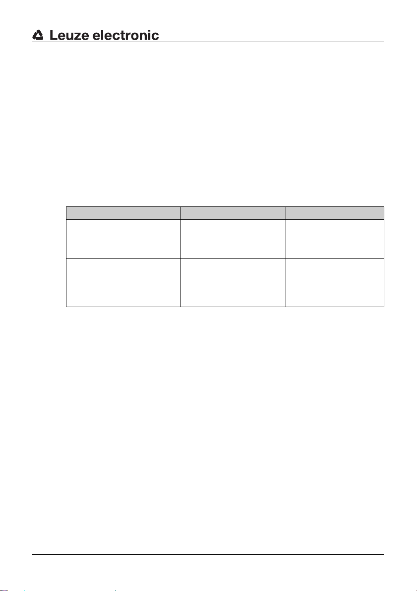
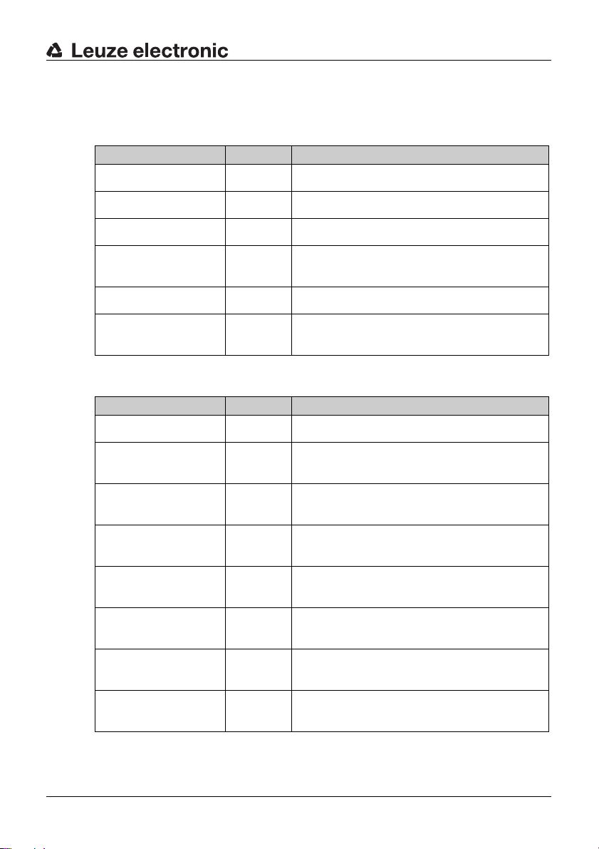
Table 1.1: Documents for the L100 Safety Locking Device
Purpose and target group Title Source
Detailed information for all
users
L100 Safe implementation
and operation (this document)
About this document
On the Internet, download
from: http://
www.leuze.com/l100/
Basic information for technicians and operating company
L100 Application information Print document part
no. 607244 included in the
delivery contents of the
product
TNT 35/7-24V
Leuze electronic L100 5
Page 5
About this document
1.2 Used symbols and signal words
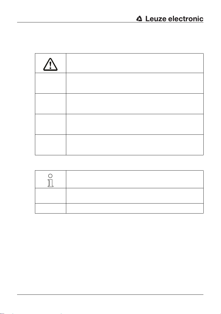
Table 1.2: Warning symbols and signal words
Symbol for dangers
NOTICE Signal word for property damage
CAUTION Signal word for minor injury
WARNING Signal word for severe injury
DANGER Signal word for life-threatening danger
Indicates dangers that may result in property damage if the measures for
danger avoidance are not followed.
Indicates dangers that may result in minor injury if the measures for danger avoidance are not followed.
Indicates dangers that may result in severe or fatal injury if the measures
for danger avoidance are not followed.
Indicates dangers that will result in severe or fatal injury if the measures
for danger avoidance are not followed.
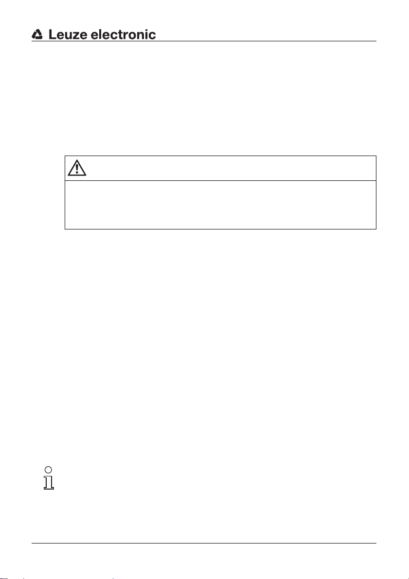
Table 1.3: Other symbols
Symbol for tips
Text passages with this symbol provide you with further information.
Symbols for action steps
ª
Text passages with this symbol instruct you to perform actions.
xxx Placeholder in the product description for all variants
6 L100 Leuze electronic
Page 6
2 Safety
Before using the Safety Locking Device, a risk evaluation must be performed
according to valid standards (e.g. EN
ISO 14121). For moun ting, o peratin g and testi ng, docu ment L 100 Sa fe im ple-
EN
mentation and operati on, app licati on infor mation as wel l as all applic able na tional
and international standards, regulations, rules and directives must be observed.
Observe and print out relevant and supplied documents and distribute to the
affected personnel.
Serious accidents may result if the voltage supply is interrupted!
If the voltage supply to the electromagnet of an electromagnetically locked
Safety Locking Device is interrupted, the protective device may be opened
immediately.
The following sta nda rds a pply for the risk e val ua tion a t th e prot ec tiv e d ev ic e prio r
to using the Safety Locking Device:
• EN ISO 14121, Safety of machinery, risk evaluation
• EN ISO 12100-1, Safety of machinery
• EN ISO 13849-1, Safety-related parts of control systems
The realizable category of the integration in control circuits according to
ISO 13849-1 is dependent on the used contact block and wiring.
EN
In particular, the fo llowin g nationa l and i nternationa l legal regulatio ns apply for the
start-up, technical inspections and work with Safety Locking Devices:
Safety
ISO 12100-1, EN ISO 13849-1,
WARNING
• Machinery directive 2006/42/EC
• L ow voltage directive 2006/95/EC
• Electromagnetic compatibility directive 2004/108/EC
• Use of work equipment directive 89/655 EEC
• Safety regulations
• Accident-prevention regulations and safety rules
• Ordinance on Industrial Safety and Health and Labor Protection Act
• Device Safety Act
For safety-related information you may also contact the local authorities (e.g.,
industrial inspectorate, employer's liability insurance association, labor inspectorate, labor protection and health authority).
Leuze electronic L100 7
TNT 35/7-24V
Page 7
Safety
2.1 Approved purpose and foreseeable improper operation
2.1.1 Proper use
• The Safety Locking Device must only be used after it has been selected in
accordance with the respectively applicable instructions and relevant standards, rules and regulations regarding labor protection and safety at work,
and after it has been installed on the machine, connected, commissioned,
and checked by a competent person.
• When selecting the Safety L ocking Dev ic e it m us t be ens ure d th at i ts s afetyrelated capability meets or exceeds the required performance level PLr
ascertained in the risk assessment.
• It must be in perfect condition and inspected regularly.
• The switching process must only be triggered by an actuator approved for
this Safety Locking Device that is connected to the moveable guard in a
non-detachable and tamperproof manner.
WARNING
A running machine can cause severe injuries!
ª Make certain that, during all conversi ons, maintenan ce work and inspec tions,
the system is securely shut down and protected against being restarted
again.
L100 Safety Locking De vi ces mu st b e co nne cted in such a way that a dangerous
state can only be activated while the protective device is closed and so that they
prevent premature opening during the lag time before the dangerous state has
ended. Electromagnetic Safety Locking Devices may only be used instead of
spring-locked Safety Locking Devices in exceptional cases and following appro
priate risk evaluation.
Connection conditions:
• dangerous state can be activated only with closed protective device and
locked locking device
• protective device cannot be opened while locking device is locked
8 L100 Leuze electronic
-
Page 8

Safety
Furthermore, the L100 Safety Locking Device must not be used under the
following conditions:
• high concentration of dust particles in the surrounding area
• rapidly changing ambient temperature (leads to condensation)
• in the event of strong phys ic al sho cks
• in explosive or easily flammable atmospheres
• the mounting locations are not sufficiently stable
• in the event of electromagnetic interference
• the safety of multiple persons is dependent on the function of this Safety
Locking Device (e.g. nuclear power plants, trains, aircraft, motor vehicles,
incinerators, medical devices)
Handling the Safety Locking Device:
ª Never unlock the Safety Locking De vice before the dangerous stat e has ended.
ª Observe the permissible environmental conditions for storage and operation
(see chapter 14).
ª Immediately replace damaged Safety Locking Devices according to these
instructions.
ª Use cable gland, insulation materials and connecting wires of the appropriate
protection rating.
ª Protect the Safety Locking Device from penetrating foreign bodies (e.g. shav-
ings, sand and blasting agent).
ª Before performing painting work, cover the actuation slot, actuator and name
plate.
ª Immediately clean any contamination from the Safety Locking Device that
impacts function according to these instructions.
ª Make no structural changes to the Safety Locking Device.
ª The Safety Locking Device must be exchanged after a maximum of 20 years.
TNT 35/7-24V
2.1.2 Foreseeable misuse
Any use other than that defined under the "approved purpose" or which goes
beyond that use of the Safety Locking Device is considered improper use!
E.g. - using without non-detachably mounted actuator
• looping into the safety circuit parts that are not relevant to safety
• using the locking device as a limit stop
Leuze electronic L100 9
Page 9

Safety
2.2 Competent personnel
Prerequisites for competent personnel:
• suitable technical training
• knows the rule s and regulations for labor protection, safety at work and
safety technology and can assess the safety of the machine
• knows the instructions for the Safety Locking Device and the machine
• was instructed by the responsib le indi viduals on the mounting and opera tion
of the machine and of the Safety Locking Device
2.3 Responsibility for safety
Manufacturer and operating company must ensure that the machine and implemented Safety Locking De vi ce func tio n pro perly and that all affected persons are
adequately informed and trained.
The type and content of all imparted information must not lead to unsafe actions
by users.
The manufacturer of the machine is responsible for:
• safe machine construction
• safe implementation of the Safety Locking Device
• imparting all relevant information to the operating company
• adhering to all regulations and directives for the safe starting-up of the
machine
The operating company is responsible for:
• instructing the operating personnel
• maintaining the safe operation of the machine
• adhering to all regulations and directives for labor protection and safety at
work
• regular testing by competent personnel
2.4 Exemption of liability
Leuze electronic GmbH + Co. KG is not liable in the following cases:
• Safety Locking Device is not used as intended
• safety notices are not adhered to
• mounting and electrical connection are not properly performed
• reasonably foreseeable misuse is not taken into account
10 L100 Leuze electronic
Page 10
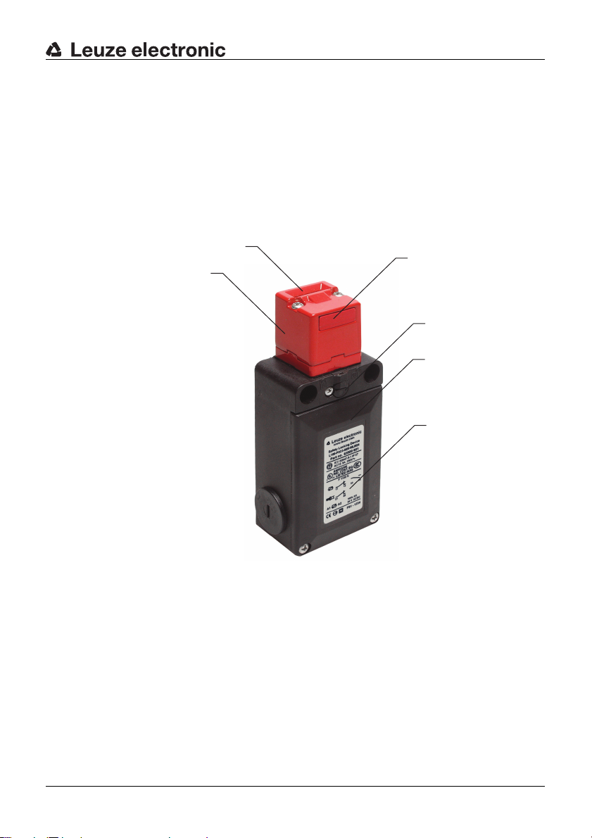
3 Device description
The Safety Locking Device of the L100 series is an electro-mechanical switching
device in a housing made of glass-fibre-reinforced and non-combustible plastic;
the device satisfies protection rating IP 66. By means of the funnel-shaped inser
tion opening, the ac tuator self-center s, even if the door is s lightly misadjus ted. The
magnet switched currents can be reduced for both variants (adjustable via a
switch). The spring-actuated models (L100-Pxxx-SLM24) are equipped with an
auxiliary release located below the deflection head.
Device description
-
3
2
1
4
5
6
1 Deflection head
2 Dust cover
3 Insertion opening for actuator
4 Auxiliary release (L100-Pxxx-SLM24)
5 Housing cove r
6 Name plate (connection data, production code and year of manufacture)
TNT 35/7-24V
Leuze electronic L100 11
Page 11
Device description
15
37.6
19.4
56
135
35
43
92
8
32
40
5.5
2.4
2.4
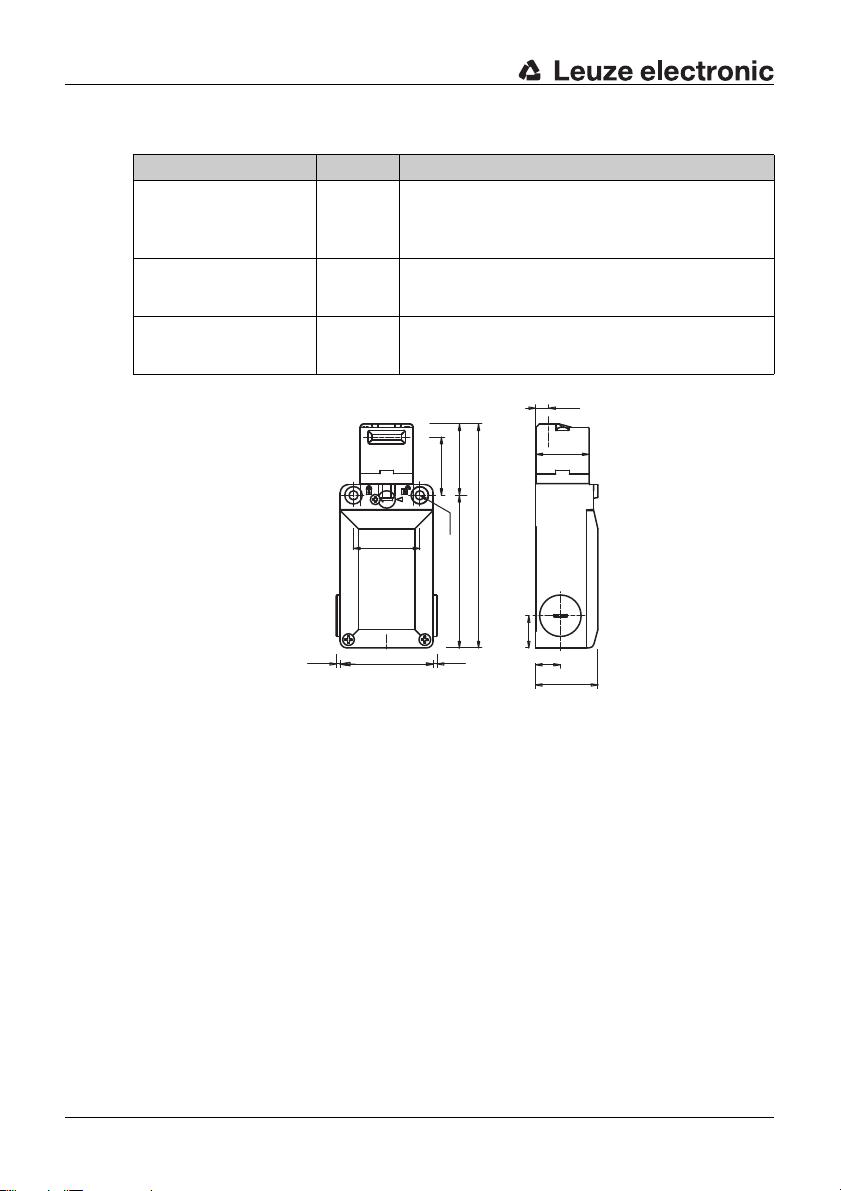
Table 3.1: L100 Safety Locking Devices
Article Part No. Description
L100-P3C3-M20-SLM24 63000600 Mechanical locking (spring force), manual auxiliary
release, slow action contacts M:(1NC+1NO)
A:(1NC)
L100-P3C3-M20-MLM24 63000601 Electromagnetic locking, slow action contacts
L100-P4C3-M20-SLM24 63000602 Mechanical locking (spring force), manual auxiliary
M:(1NC+1NO) A:(1NC)
release, slow action contacts M:(2NC) A:(1NC)
Figure 3.1: Dimensions of L100-P3C3-M20-SLM24 and L100-P4C3-M20-
SLM24 in mm
12 L100 Leuze electronic
Page 12
Device description
15
37.6
19.4
56
135
35
43
92
8
32
40
5.5
2.4
2.4
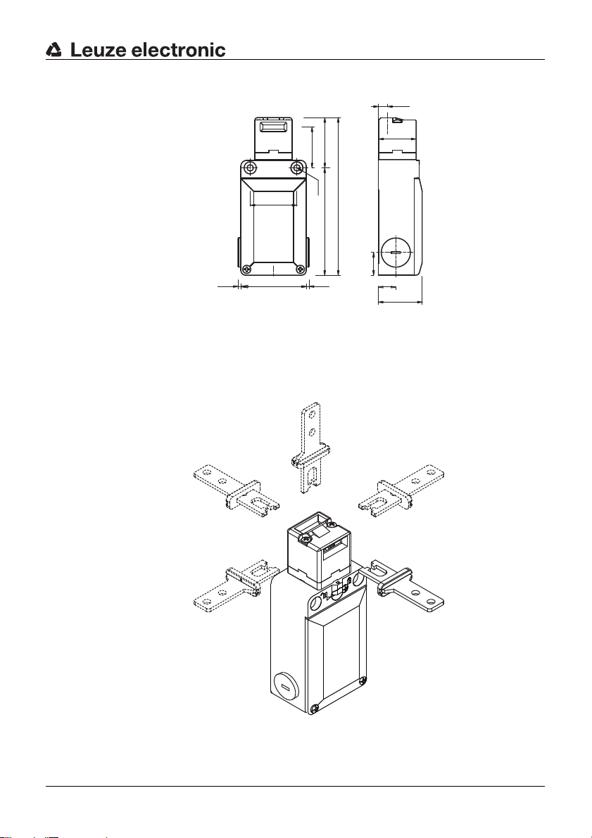
Figure 3.2: Dimensions of L100-P3C3 -M2 0-M LM 24 in mm
The deflection head ca n be turne d in 90° inc rement s and set to 5 app roach direc -
tions. A selection of different actu ators ensures that the Safety Lock ing Device can
be mounted in any position.
Leuze electronic L100 13
Figure 3.3: Approach directions
TNT 35/7-24V
Page 13

Functions
4 Functions
4.1 Spring locking
With the L100-P3C3-M20-SLM24 and L100-P4C3-M20-SLM24, the safety
contacts clos e wh en the actuator mov es in , and the actuator i s me cha ni cal ly h eld
in the locked positio n by the spring forc e. The dangerous pro cess can be activa ted
via the safety switching devi ce .
After the dangerous proc es s has st op ped , th e o pera tin g v ol tage for unlocking the
electromagnet is applied and the actuator is released. The protective device can
be opened. In the event o f failure of the op erating v oltage, re lease is also pos sible
via the auxiliary release.
4.2 Electromagnetic locking
With the L100-P3C3-M20-MLM24, the safety contact for the position monitoring
of the protective d ev ic e c lo se s when th e a ctuator is moved i n. The electromagne t
is energized and ho lds the actuator in the locked po sition. The da ngerous proce ss
can be activated via the safety switching device.
On release, the voltage supply to the electromagnet is interrupted. The electromagnet releases the actuator and the protective device can be opened.
14 L100 Leuze electronic
Page 14

5 Applications
Safety Locking Device s with spring l ocking are suita ble for e.g. position m onitoring
and locking the following protective devices:
• turning or swiveling moveable guards
• laterally moveable protective gratings or sliding gates
Safety Locking Devices with electromagnetic lock are used primarily as locks for
moveable guards to prevent undesired process interruptions.
By means of the switched-current reduction option, larger systems can be
equipped with multiple L100 Safety Locking Devices. With magnet activation,
possible voltage peaks associated with switching on an d off can be reduced in this
way.
Applications
Leuze electronic L100 15
TNT 35/7-24V
Page 15

Mounting
6 Mounting
WARNING
Severe accidents may result if the Safety Locking Device is not mounted
properly!
The protective function of the Safety Locking Device is only ensured if used in
the intended area of application and if it is mounted professionally.
ª Mounting may only be performed by competent personnel.
ª Observe standards, regulations and these instructions.
ª Protect the housing and deflection head from material s penetrating th e enclo-
sure (environmental conditions (see chapter 14)).
ª Test to ensure proper function.
6.1 Adjusting the deflection head
ª Unscrew the 2 screws on the deflection head.
ª Turn the deflection head in the desired direction.
ª Tighten the 2 screws on the deflection head with 0.7–0.9 Nm.
ª Close unused opening with the dust cover.
16 L100 Leuze electronic
Page 16

6.2 Mounting the Safety Locking Device
Prerequisites for mounting:
• deflection head has been set
• fully assembled
ª Select the mounting location so that the following conditions are satisfied:
• Safety Locking De vic e and ac tuator ca n be wel l match ed to one another a nd
permanently mounted
• auxiliary release is accessible to qualified personnel
• accessible to qualified personnel for testing and replacement
ª Position washers and screw down Safety Locking Device with 2–3 Nm.
Mounting
6.3 Mounting the actuator
NOTICE
The Safety Locking Device may be damaged if mounted improperly!
ª Use separate mechanical limit stop for the moving part of the protective
device.
ª Align actuator so that it does not hit or rub against the edges of the inse rtio n
opening.
Prerequisites for proper function:
• actuator is not deformed or damaged
• actuator is appropriate for the Safety Locking Device
Proper function is ensured only with original accessories (see chapter 13).
Leuze electronic L100 17
TNT 35/7-24V
Page 17

Mounting
0,5 ... 5 mm
ª Align actuator.
Wrong Correct
Play for the actuator in the closed state: 0.5–5 mm.
18 L100 Leuze electronic
Page 18

Mounting
ª Secure actuator with r ivets or tamperproof screws so that it cannot be
detached.
Leuze electronic L100 19
TNT 35/7-24V
Page 19

Electrical connection
7 Electrical connection
WARNING
Serious accidents may result if the electrical connection is faulty!
ª Electrical connection may only be performed by competent personnel.
7.1 Setting the switched-current reduction
With magnet activation, this function enables the reduction of switch-on and
switch-off peaks by splitting into up to 4 groups.
DANGER
Risk of death by electric shock!
ª Interrupt the voltage supply to the Safety Locking Device.
ª Unscrew the housing cover.
ª Remove the two screws on the black protective cover of the electromagnet.
ª Remove the protective cover.
ª Use an appropriate tool to set the DIP swi tc hes of the Safe ty Loc k ing Dev ic es
to different combinations (for more than 4 Safety Locking Devices, split uniformly).
ª Mount the black protective cover and screw down with 0.8 Nm.
ª Tighten the housing cover with 0.7–0.9 Nm.
20 L100 Leuze electronic
Page 20

7.2 Connecting the contact bloc k
222112
11
34
33
222112
11
34
33
323112
11
22
21
323112
11
22
21
Prerequisites:
• temperature stability of the cable insulation material must be greater than
the maximum temperature of the housing (see chapter 14)
• cable gland with appropriate protection rating
• maximum current load is observed (see chapter 14)
Figure 7.1: Contact block 2NC + 1NO (L100-P3xxx)
Electrical connection
Figure 7.2: Contact block 2NC + 1NC (L100-P4xxx)
DANGER
Risk of death by electric shock!
ª Interrupt the voltage supply to the Safety Locking Device.
ª Unscrew the housing cover.
ª Connect the electromagnet via terminals A1 and A2.
ª Connect the contact block according to the appli cation-spec ific circu it diagram .
Leuze electronic L100 21
TNT 35/7-24V
Page 21

Electrical connection
Var. B
Var. A
MSI-SR4
L100-P3C3-M20-SLM24
-K3
-A2
-K4
-K4
-K3
11 12 21 22
-A1
33 34
x1
x2
0V
PE PE
0V
L-
13 23 41S22 S12 S31 S33 S34 S35
33
+24V
2 AOPD-
1 AOPD+
2 AOPD+
IV-0
RES-0
RES-I
1
2
L+
-K3
-K4
14 24 42
0V
34
1
2
+24V +24V
A1
A2
-K3
L- L-
*
A1
A2
-K4
*
121
2
L+ L+
1
2
-S1
* Spark extinction circuit, suitable spark extinction provided
Figure 7.3: Connection example L100-P3C3-M20-SLM24
ª Tighten cable terminal screws with 0.6–0.8 Nm.
ª Tighten the housing cover with 0.7–0.9 Nm.
22 L100 Leuze electronic
Page 22

8 Setting the device into service
WARNING
Serious accidents may result if the Safety Locking Device is unlocked
prematurely!
ª Before unlocking the Sa fety Lockin g Device and op ening the pro tective
device, wait until the dangerous state has ended.
Prerequisites:
• Safety Locking Device is mounted and connected according to these
instructions
• operating personnel have been trained in the correct use
ª Test the function of the Safety Locking Device (see chapter 9).
The Safety Locking Device is then ready for use.
Setting the device into service
Leuze electronic L100 23
TNT 35/7-24V
Page 23

Testing
9 Testing
L100 Safety Locking Devices are maintenance free. Nevertheless, they must be
replaced after maximum 800,000 switching cycles.
ª Always replace the entire Safety Locking Device including actuator.
ª For the testing intervals, observe nationally applicable regulations.
ª Document all tests in a comprehensible manner.
9.1 To be performed prior to the initial start-up by competent personnel
ª Check whether the Safety Locking Device is opera ted according to its specifie d
environmental conditions (see chapter 14).
ª Test to ensure proper mechanical and electrical function (see chapter 9.2).
9.2 To be performed periodically by competent personne l
Mechanical function
ª Stop the dangerous state and open the protective device.
ª Check that the components are securely fastened.
ª Test the cable entry for leaks.
ª Check Safety Locking Device and actuator for damage, dep osits , deforma tion
and wear.
ª If present, test auxiliary release.
ª Test several times whether the actuator can be easily moved into the Safety
Locking Device.
Electrical function
WARNING
Severe accidents may result if tests are not performed properly!
ª Make certain that there are no persons in the danger zone.
ª Stop the dangerous state and open the protective device.
ª Make certain that the machine cannot be st arted whi le the pr otecti ve dev ice is
open.
ª Close the protective device and start the machine.
24 L100 Leuze electronic
Page 24

ª Make certain that the protective device cannot be opened until after the
machine has been shut down and the Safety Locking Device has been
released.
ª Make certain that the dangerous state ends before the protective device can
be opened.
9.3 To be performed daily by the operating personnel
WARNING
Severe accidents may result if tests are not performed properly!
ª Make certain that there are no persons in the danger zone.
ª Stop the dangerous state and open the protective device.
ª Check the Safety Locking Device and actuator for damage or tampering.
ª Make certain that the machine cannot be st arted whi le the pr otecti ve dev ice is
open.
ª Close the protective device and start the machine.
ª Make certain that the protective device cannot be opened until after the
machine has been shut down and the Safety Locking Device has been
released.
Testing
Leuze electronic L100 25
TNT 35/7-24V
Page 25

Cleaning
10 Cleaning
There must be no soiling (e.g. shavings or dust) present, especially in the deflection head of the Safety Locking Device.
Prerequisites for cleaning:
• protective device is opened and machine is switched off
• voltage supply for the Safety Locking Device is interrupted
ª Periodically clean the Safety Locking Device while the protective device is
opened (e.g. with vacuum cleaner).
26 L100 Leuze electronic
Page 26

11 Disposing
ª The nationally valid regulations for electro-mechanical components are to be
observed when disposing.
Disposing
Leuze electronic L100 27
TNT 35/7-24V
Page 27

Service and support
12 Service and support
Telephone number for 24-hour standby service:
+49 (0) 7021/ 573-0
Service hotline:
+49 (0) 8141/ 5350-111
Monday to Thursday, 8.00 a.m. to 5.00 p.m. (UTC+1)
Friday, 8.00 a.m. to 16.00 p.m. (UTC +1)
E-mail:
service.protect@leuze.de Return address for repairs: Service Center
Leuze electronic GmbH + Co. KG
In der Braike 1
D-73277 Owen - Teck / Germany
Leuze electronic offers a regular safety inspection by a competent person.
28 L100 Leuze electronic
Page 28
13 Accessories
Table 13.1: Actuators of the AC-AH series for the L100 Safety Locking Device
Article Part No. Description
AC-AH-S 63000720 Straight
AC-AH-A 63000721 Angled
AC-AH-F4 63000722 Straight, flexible, 4 directions
Accessories
AC-AH-F2J2 63000723 Straight, flexible, 2 directions, alignable 2 direc-
tions
AC-AH-F1J2 63000724 Straight, flexible, 1 direction, alignable 2 directions
AC-AH-F4J2-TK 63000725 Straight, flexible, 4 directions, alignable 2 direc-
tions, rotatable head
Table 13.2: Accessories for the L100 Safety Locking Device
Article Part No. Description
AC-A-M20-12NPT 63000843 Adapter, M20 x 1.5 on 1/2 NPT
AC-PLP-8 63000844 Built-in plug, M12, plastic, with internal 8-pin con-
nection cable
AC-KL-AH 63000846 Actuator interlock, for locking the actuator intro-
duction
CB-M12-5000E-5GF 678055 PUR, 5-pin, 5 m, shielded, M12 coupling, straight,
prefabricated on one end
CB-M12-10000E-5GF 678056 PUR, 5-pin, 10 m, shielded, M12 coupling,
straight, prefabricated on one end
CB-M12-15000E-5GF 678057 PUR, 5-pin, 15 m, shielded, M12 coupling,
straight, prefabricated on one end
CB-M12-25000E-5GF 678058 PUR, 5-pin, 25 m, shielded, M12 coupling,
straight, prefabricated on one end
TNT 35/7-24V
CB-M12-5000E-8GF 678060 PUR, 8-pin, 5 m, shielded, M12 coupling, straight,
Leuze electronic L100 29
prefabricated on one end
Page 29

Accessories
32
15
6152226
5.5
10
R>300
R>500
R>500
30
16.2
2.5
Article Part No. Description
CB-M12-10000E-8GF 678061 PUR, 8-pin, 10 m, shielded, M12 coupling,
CB-M12-15000E-8GF 678062 PUR, 8-pin, 15 m, shielded, M12 coupling,
straight, prefabricated on one end
straight, prefabricated on one end
CB-M12-25000E-8GF 678063 PUR, 8-pin, 25 m, shielded, M12 coupling,
straight, prefabricated on one end
13.1 Accessory dimensional drawings
Figure 13.1: AC-AH-S actuator
30
15
26 15.3
R>300
16.2
10
15
6
Ø 5.5
R>500
Figure 13.2: AC-AH-A actuator
30 L100 Leuze electronic
32
2.5
R>500
Page 30

Figure 13.3: AC-AH-F4 actuator
32
30
13
20
11
4.5
8°
8°
8°
8°
16
2426
R>300
R>500
R>500
2.5
16.2
7
4.2
30
20
7
16.2
13
7
5°
4.5
12°
R>100
20
26
22
2.5
R>100
5°
Accessories
4
32
12°
R>100
11
Figure 13.4: AC-AH-F2J2 actuator
Leuze electronic L100 31
TNT 35/7-24V
Page 31

Accessories
32
1126
37
2.5
11°
40
56
16
8.6
5.2
2.4
R>100
R>500
R>500
16.2
5.5
R
80
≥
≥
12°
12°
12°
12°
R
80
R 80
2.5
20
4.8
Ø 4.2
≥
6.5
28
12°
12°
8.5
39
5.2
1310.826
16.2
30
Figure 13.5: AC-AH-F1J2 actuator
Figure 13.6: AC-AH-F4J2-TK actuator
32 L100 Leuze electronic
Page 32

14 Technical data
Table 14.1: General
Technical data
Switch type Interlock device with locking according to
Actuator, external AC-AHxx series: straight, angled,
Lock type L100-Pxxx-SLM24: spring force
Lock actuation L100-Pxxx-SLM24: spring
Approach actuation directions 1 x above, 4 x side (90°)
Approach speed min. 1 mm/s, max. 0.5 m/s
Actuation force (pull-out) 30 N
Actuation path, min. with forced separation 10 mm
Mechanical life time in accordance with
IEC 60947-5-1
Actuation frequency according to
IEC 60947-5-1
Service life (T
EN ISO 13849-1
) in accordance with
M
EN 1088
spring-mounted, adjustable
L100-Pxxx-MLM24: electromagnetic
L100-Pxxx-MLM24: electromagnet
6
0.8 x 10
max. 600 per hour
20 years
switching cycles
TNT 35/7-24V
Leuze electronic L100 33
Page 33

Technical data
Number of cycles before dangerous failure
(B10d) according to EN 61810-2
Usage category according to EN 60947-5-1
Maximum load when using 5-pin cables:
Maximum load when using 8-pin cables:
Dimensions (dimensional drawings) see chapter 3
5,000,000
AC 15 (Ue / Ie):
250 V / 6 A
400 V / 4 A
500 V / 1 A
DC 13 (Ue / Ie):
24 V / 6 A
125 V / 1.1 A
250 V / 0.4 A
24 V / 4 A(see chapter 13)
24 V / 2 A(see chapter 13)
Table 14.2: Safety
Protection rating IP 66
Contact protection protective insulation O
Recoil tolerance 4.5 mm
Interlocking force max. 1100 N
Contact allocation L100-P3xxx:
magnet: 1NC + 1NO, actuator: 1NC
L100-P4xxx:
magnet: 2NC, actuator: 1NC
Contact material silver alloy
Switching principle slow-action contact
Opening of contact positive-forced
Rated insulation voltage 400 V AC
Conventional thermal current max. 10 A
Short-circuit protection according to
IEC 60269-1
Magnet operating voltage and tolerance 24 V DC (–10 % to +25 %)
34 L100 Leuze electronic
magnet: 1.0 A, 24 V, type aM
safety circuit: 10 A, 500 V, type aM
Page 34

Switch-on time 100 %
Power consumption average 20 VA
Switch-on power limit, adjustable 4-way
Table 14.3: Housing
Technical data
Housing material fiberglass-reinforced, thermo-plastic plastic,
self-extinguishing
Table 14.4: Connection
Number of cable entries 3
Type of cable entry M20 x 1.5
Conductor cross-section (stranded) 1 x 0.34 mm
2
to 2 x 1.5 mm
2
Table 14.5: Environment
Temperature range, operation –25 ... +60 °C
Degree of contamination, external,
according to EN 60947-1
3
These tables do not apply in comb ination w ith additio nal M12 plug or con necting
cable except where these components are explicitly mentioned.
TNT 35/7-24V
Leuze electronic L100 35
Page 35

EC Declaration of Conformity
15 EC Declaration of Conformity
You can download this EC Declaration of Conformity as a PDF from:
http://www.leuze.com/l100/
36 L100 Leuze electronic
 Loading...