

Page 1
L10
Safety Locking Devices
EN 2011/09 - 607300
We reserve the right to
make technical changes
SAFE IMPLEMENTATION AND OPERATION
Original operating instructions
Page 2

© 2011
Leuze electronic GmbH + Co. KG
In der Braike 1
D-73277 Owen - Teck / Germany
Phone: +49 7021 573-0
Fax: +49 7021 573-199
http://www.leuze.com
info@leuze.de
Page 3

1 About this document............................................................................................5
1.1 Other applicable documents ................................................................................................5
1.2 Used symbols and signal words ..........................................................................................6
2 Safety................................................................................................................... 7
2.1 Approved purpose and foreseeable improper operation......................................................8
2.1.1 Proper use .....................................................................................................................................8
2.1.2 Foreseeable misuse ......................................................................................................................9
2.2 Competent personnel.........................................................................................................10
2.3 Responsibility for safety.................................................... ........................... ......................10
2.4 Exemption of liability..........................................................................................................11
3 Device description.............................................................................................12
4 Functions........................................................................................................... 17
5 Applications .......................................................................................................18
6 Mounting............................................................................................................19
6.1 Adjusting the deflection head.................................................................................. .... .. .... .19
6.2 Mounting the Safety Locking Device........................................................................... .. .... .21
6.3 Mounting the actuator ................................................................. ..... .. .. .... .. .. .. .. ....... .. .. .. .. ...22
7 Electrical connection..........................................................................................24
7.1 Connecting the contact block................................................................... .. .... .. ..... .... .. .. .... .24
8 Setting the device into service...........................................................................27
9 Testing...............................................................................................................28
9.1 To be performed prior to the initial start-up by competent personnel................................. 28
9.2 To be performed periodically by competent personnel......................................................28
9.3 To be performed daily by the operating personnel ............................................................29
10 Cleaning............................................................................................................. 30
11 Disposing...........................................................................................................31
12 Service and support........................................................................................... 32
13 Accessories .......................................................................................................33
13.1 Accessory dimensional drawings.......................................................................................34
14 Technical data ...................................................................................................37
Leuze electronic L10 3
TNT 35/7-24V
Page 4

15 EC Declaration of Conformity............................................................................40
4 L10 Leuze electronic
Page 5
1 About this document
1.1 Other applicable documents
The information on the L10 Safety Locking Device is di vi ded into tw o do cum en ts .
Document "L10 Application information" contains only the most important safety
notices.
ª For the safe implementation, testing and operation, download document L10
Safe implementation and operation from http://www.leuze.com/l10/ or request
it from service.schuetzen@leuze.de or tel. +49 8141 5350-111.
Table 1.1: Documents for the L10 Safety Locking Device
Purpose and target group Title Source
Detailed information for all users L10 Safe implementation
and operation (this document)
About this document
On the Internet, download
from: http://
www.leuze.com/l10/
Basic information for technicians
and operating company
L10 Application information Print document part
no. 607242 included in
the delivery contents of
the product
TNT 35/7-24V
Leuze electronic L10 5
Page 6
About this document
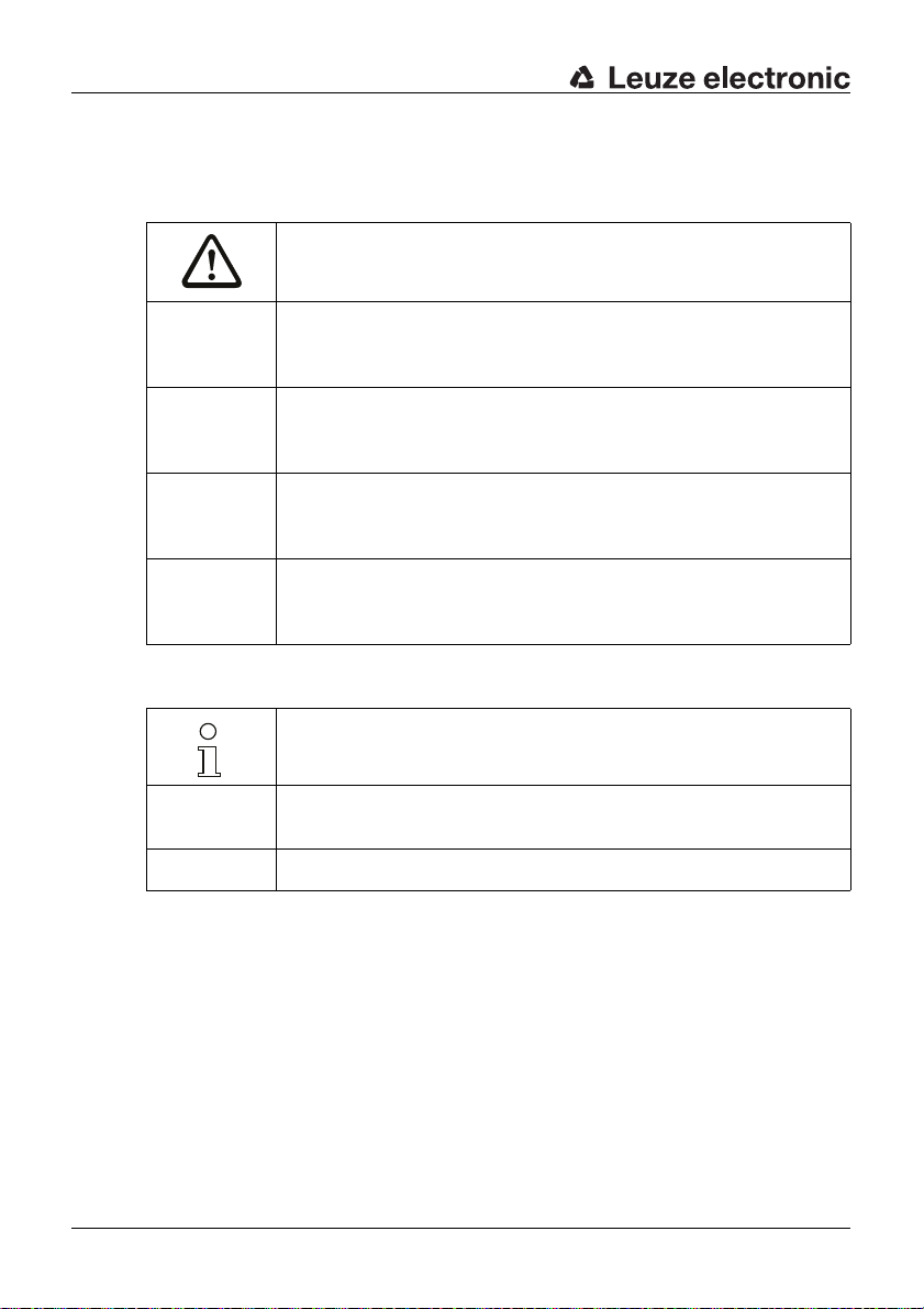
1.2 Used symbols and signal words
Table 1.2: Warning symbols and signal words
Symbol for dangers
NOTICE Signal word for property damage
CAUTION Signal word for minor injury
WARNING Signal word for severe injury
DANGER Signal word for life-threatening danger
Indicates dangers that may result in property damage if the measures for
danger avoidance are not followed.
Indicates dangers that may result in minor injury if the measures for danger avoidance are not followed.
Indicates dangers that may result in severe or fatal injury if the measures
for danger avoidance are not followed.
Indicates dangers that will result in severe or fatal injury if the measures
for danger avoidance are not followed.
Table 1.3: Other symbols
Symbol for tips
Text passages with this symbol provide you with further information.
Symbols for action steps
ª
Text passages with this symbol instruct you to perform actions.
xxx Placeholder in the product description for all variants
6 L10 Leuze electronic
Page 7
2 Safety
Before using the Safety Locking Device, a risk evaluation must be performed
according to valid standards (e.g. EN
ISO 14121). For mounting, operating and testing, document L10 Safe imple-
EN
mentation and operati on, app licati on infor mation as wel l as all applic able na tional
and international standards, regulations, rules and directives must be observed.
Observe and print out relevant and supplied documents and distribute to the
affected personnel.
The following sta nda rds a pply for the risk e val ua tion a t the protective dev ice prior
to using the Safety Locking Device:
• EN ISO 14121, Safety of machinery, risk evaluation
• EN ISO 12100-1, Safety of machinery
• EN ISO 13849-1, Safety-related parts of control systems
The realizable category of the integration in control circuits according to
ISO 13849-1 is dependent on the used contact block and wiring.
EN
In particular, the fo llowin g nationa l and i nternationa l legal regulatio ns apply for the
start-up, technical inspections and work with Safety Locking Devices:
• Machiner y directive 2006/42/EC
• Low voltage directive 2006/95/EC
• Use of work equipment directive 89/655 EEC
• Safety regulations
• Accident-prevention regulations and safety rules
• Ordinance on Industrial Safety and Health and Labor Protection Act
• Device Safety Act
Safety
ISO 12100-1, EN ISO 13849-1,
For safety-related information you may also contact the local authorities (e.g.,
industrial inspectorate, employer's liability insurance association, labor inspectorate, labor protection and health authority).
Leuze electronic L10 7
TNT 35/7-24V
Page 8
Safety
2.1 Approved purpose and foreseeable improper operation
2.1.1 Proper use
• The Safety Locking Device must only be used after it has been selected in
accordance with the respectively applicable instructions and relevant standards, rules and regulations regarding labor protection and safety at work,
and after it has been installed on the machine, connected, commissioned,
and checked by a competent person.
• When selecti ng the Sa fety Lock ing D evice it must be ens ure d th at i ts s afetyrelated capability meets or exceeds the required performance level PLr
ascertained in the risk assessment.
• It must be in perfect condition and inspected regularly.
• The switching process must only be triggered by an actuator approved for
this Safety Locking Device that is connected to the moveable guard in a
non-detachable and tamperproof manner.
WARNING
A running machine can cause severe injuries!
ª Make certain that, during all conversi ons, maintenan ce work and inspec tions,
the system is securely shut down and protected against being restarted
again.
L10 Safety Locking Devices must be connected in such a way that a dangerous
state can only be activated while the protective device is closed and so that the
dangerous state has ended before the protective device can be opened. They
must not be used if the point of operation can be accessed during the lag time
before the dangerous state has ended.
Connection conditions:
• dangerous state can be activated only with closed protective device and
locked locking device
• protective device cannot be opened while locking device is locked
• manual unl ock ing of the loc kin g de vice whil e the machi ne is running trig gers
a stop command; the dan gerous state is ended be fore the prote cti ve device
can be opened
8 L10 Leuze electronic
Page 9

Safety
Furthermore, the L10 Safety Locking Device must not be used under the following
conditions:
• lag time of the dangerous state is greater than the minimum time delay of
the manual actuator release
• high concentration of dust particles in the surrounding area
• rapidly changing ambient temperature (leads to condensation)
• in the event of strong phys ic al sho cks
• in explosive or easily flammable atmospheres
• the mounting loca tion s are not sufficiently stable
• the safety of multiple persons is dependent on the function of this Safety
Locking Device (e.g. nuclear power plants, trains, aircraft, motor vehicles,
incinerators, medical devices)
Handling the Safety Locking Device:
ª Observe the permissible environmental conditions for storage and operation
(see chapter 14).
ª Immediately replace damaged Safety Locking Devices according to these
instructions.
ª Use cable gland, insulation materials and connecting wires of the appropriate
protection rating.
ª Protect the Safety Locking Device from penetrating foreign bodies (e.g. shav-
ings, sand and blasting agent).
ª Before performing painting work, cover the actuation slot, knurled nut or lock
and name plate.
ª Immediately clean any contamination from the Safety Locking Device that
impacts function according to these instructions.
ª Make no structural changes to the Safety Locking Device.
ª The Safety Locking Device must be exchanged after a maximum of 20 years.
TNT 35/7-24V
2.1.2 Foreseeable misuse
Any use other than that defined under the "approved purpose" or which goes
beyond that use of the Safety Locking Device is considered improper use!
e.g.
• Using without non-detachably mounted actuator
• looping into the safety circuit parts that are not relevant to safety
• using the locking device as a limit stop
• giving the keys to unauthorized persons
Leuze electronic L10 9
Page 10

Safety
2.2 Competent personnel
Prerequisites for competent personnel:
• suitable technical training
• knows the rules and regulations for labor protection, safety at work and
safety technology and can assess the safety of the machine
• knows the instructions for the Safety Locking Device and the machine
• was instruct ed by t he responsib le indi viduals on the mountin g and opera tion
of the machine and of the Safety Locking Device
2.3 Responsibility for safety
Manufacturer and operating company must ensure that the machine and implemented Safety Locking De vi ce func tio n pro perly and that all affected pers on s are
adequately informed and trained.
The type and content of all imparted information must not lead to unsafe actions
by users.
If Safety Locking Devices feature key operation, the keys may only be given to
authorized person s who ha ve be en ins truct ed on the in terplay of sy stem /mach ine
and the Safety Locking Device.
The manufacturer of the machine is responsible for:
• safe machine construction
• safe implementation of the Safety Locking Device
• imparting all relevant information to the operating company
• adhering to all regulations and directives for the safe starting-up of the
machine
The operating company is responsible for:
• instructing the operating personnel
• maintaining the safe operation of the machine
• adhering to all regulations and directives for labor protection and safety at
work
• regular testing by competent personnel
10 L10 Leuze electronic
Page 11

2.4 Exemption of liability
Leuze electronic GmbH + Co. KG is not liable in the following cases:
• Safety Locking Device is not used as intended
• safety notices are not adhered to
• mounting and electrical connection are not properly performed
• the manual delay time is not allowed to elapse (e.g. due to improper operation, use of auxiliary equipment or tampering)
• reasonably foreseeable misuse is not taken into account
Safety
Leuze electronic L10 11
TNT 35/7-24V
Page 12
Device description
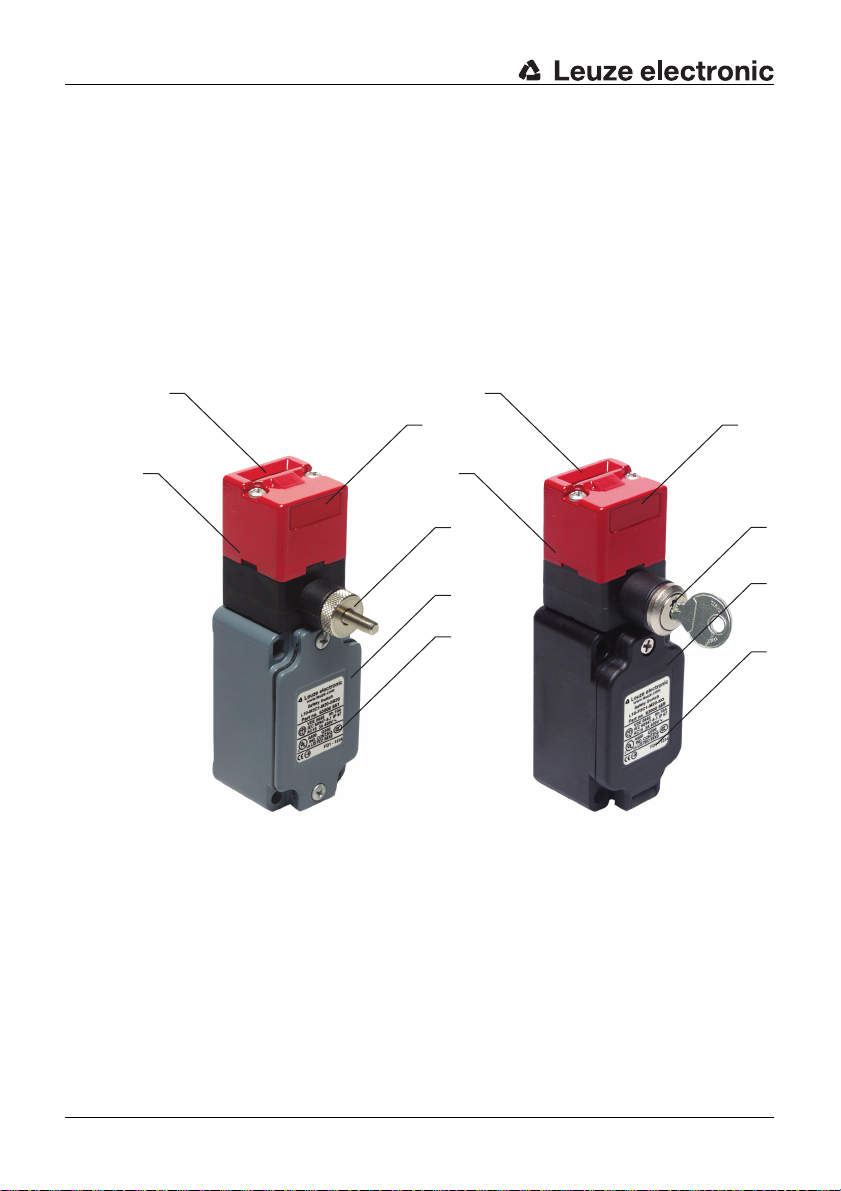
3 Device description
The Safety Locking Device of the L10 series is an electro-mechanical switching
device in a housing made of metal or glass-fiber-reinforced and non-combustible
plastic; the devic e satisfies pro tection ratin g IP 67. By me ans of the f unnel-shaped
insertion opening, the actuator self-centers, even if the door is slightly misad
justed. The locking/unlocking delay is manually adjusted by means of either a
knurled nut or a key (2 pieces included with delivery). A possible time delay must
be taken into account separately in this case.
Various mechanical and temporal requirements can be realized inexpensively
with the available models.
-
2
3
1
1 Deflection head
2 Insertion opening for actuator
3 Dust cover
4 Knurled nut or key for locking/unlocking, delay (see chapter 14)
5 Housing cove r
6 Name plate (connection data, production code and year of manufacture)
2
1
4
5
6
3
4
5
6
12 L10 Leuze electronic
Page 13

Device description
Table 3.1: L10 Safety Locking Devices
Article Part No. Description
L10-P2C1-M20-SB20 63000550 Normal duty, plastic, slo w action contacts (2NC), man-
ual time delay up to 20 s, operational distance approx.
10 mm
L10-P3C1-M20-SB20 63000552 Normal duty, plastic , slow action contacts (2NC+1NO),
manual time delay up to 20 s, operational distance
approx. 10 mm
L10-M2C1-M20-SB20 63000551 Heavy duty, metal, slow action contacts (2NC), manual
time delay up to 20 s, operational distance approx.
10 mm
L10-M3C1-M20-SB20 63000553 Heavy duty, metal, slow action contacts (2NC+1NO),
manual time delay up to 20 s, operational distance
approx. 10 mm
L10-P3C1-M20-LB10 63000554 Normal duty, plastic , slow action contacts (2NC+1NO),
manual time delay up to 10 s, operational distance
approx. 24 mm
L10-P3C1-M20-LB20 63000555 Normal duty, plastic , slow action contacts (2NC+1NO),
manual time delay up to 20 s, operational distance
approx. 24 mm
L10-P3C1-M20-KO 63000558 Normal duty , pl astic, slo w action contacts (2NC+1NO),
manual time delay via key operation, operational distance approx. 12 mm
L10-M3C1-M20-KO 63000559 Heavy duty, metal, slow action contacts (2NC+1NO),
manual time delay via key operation, operational distance approx. 12 mm
TNT 35/7-24V
Leuze electronic L10 13
Page 14

Device description
15
38 11 13
30
40
32
12.6 13
25.6
60 48.5
8
5.3
30
6.5
123
8
5.3x7.3
Figure 3.1: Dimensions of L10-P2C1-M20-SB20 and L10-P3C1-M20-SB20 in
mm
13
16
30
32
8
39
10 13
8
122.5
60 48.5
6
30
40
5.2
12.6
25.6
5.2x7.2
Figure 3.2: Dimensions of L10-M2C1-M20-SB20 and L10-M3C1-M20-SB20 in
mm
14 L10 Leuze electronic
Page 15

Device description
5.2x7.2
40
30
39
16
8
122.5
12.6
8
32
5.2
30
60 48.5
6
12.6
23
5.3x7.3
40
30
39
16
8
122.5
8
32
39.4
25.2
75.4
60
6
48.5
30
5.3
Figure 3.3: Dimensions of L10-P3C1-M20-LB10 and L10-P3C1-M20-LB20 in
mm
Figure 3.4: Dimensions of L10-P3C1-M20-KO in mm
Leuze electronic L10 15
TNT 35/7-24V
Page 16

Device description
8
8
32
123
5.3
30
25.2
60 48.5.
15
5.3x7.3.
30
6.5
40
39.4
Figure 3.5: Dimensions of L10-M3C1-M20-KO in mm
The actuation directions of the deflection head and knurled nut or lock can be
adjusted i n 90° incremen ts. By means of 5 possible ap proach directi ons and a
selection of di ffe rent ac tua tors , the Safety Lockin g De vi ce c an be m oun ted in any
position.
38
75.4
Figure 3.6: Approach directions
16 L10 Leuze electronic
Page 17

4 Functions
1234
1°
2°
The positive-opening contacts close if:
• the actuator is moved in
• the locking device is locked
The dangerous state can only be activated via the safety switching device while
the safety contacts are closed. During the first clockwise turns of the knurled nut
or by turning the key by 180°, the contacts are opened and a stop signal is transmitted to the downstream safety switching device. The actuator is not released
until the knurled nut has been turned to the right limit stop and the locking device
has unlocked. During this manual time delay (see chapter 14), the dangerous
state must be stopped in order for the protective device to be opened safely. The
Safety Locking Device can only be locked if the actuator is moved in.
1 Machine is running, locking device is locked
2 Machine coasts as the knurled nut is turned
3 Machine has stopped, locking device is unlocked
4 Protective device can be opened
Figure 4.1: Example for the manual delay by turning the knurled nut
Functions
1 Machine is running, locking device is locked
2 The machine stopped after the key was turned by 180°, locking device is unlocked
3 Protective device can be opened
Figure 4.2: Example for the manual delay by turning the key by 180°
When using locking devices with key operation, it is essential to comply with the
necessary delay times.
Leuze electronic L10 17
TNT 35/7-24V
Page 18

Applications
5 Applications
The manual locking/unlocking function makes the L10 Safety Locking Device
suitable for systems with protective devices that are used only occasionally or
that are located relatively far away on which no magnet activation is provided.
The Safety Locking Device is suitable for e.g. the following protective devices:
• turning or swiveling moveable guards
• laterally moveable protective gratings or sliding gates
• seldom used maintenance doors or covers
18 L10 Leuze electronic
Page 19

6 Mounting
WARNING
Severe accidents may result if the Safety Locking Device is not mounted
properly!
The protective function of the Safety Locking Device is only ensured if used in
the intended area of application and if it is mounted professionally.
ª Mounting may only be performed by competent personnel.
ª Observe standards, regulations and these instructions.
ª Protect the housing and deflection head from material s penetrating th e enclo-
sure (environmental conditions (see chapter 14)).
ª Test to ensure proper function.
6.1 Adjusting the deflection head
ª Loosen the 2 screws on the deflection head.
Mounting
ª If necessary, loosen the 4 screws on the locking/unlocking unit.
Leuze electronic L10 19
TNT 35/7-24V
Page 20

Mounting
ª Turn the deflection head and the locking/unlocking unit in the desired direc-
tions.
ª If necessary, retighten the 4 screws on the locking/unlocking unit with 0.8–
1.2 Nm.
ª Replace the 2 screws on the deflection head with the supplied safety screws
and tighten with 0.8–1.2 Nm.
ª Close unused opening with the dust cover.
20 L10 Leuze electronic
Page 21

6.2 Mounting the Safety Locking Device
Prerequisites for mounting:
• deflection head has been set
• fully assembled
• the 2 screws on the deflection head have been replaced with the supplied
safety screws
ª Select the mounting location so that the following conditions are satisfied:
• Safety Locking De vice and actuator can be w ell mat ched to o ne anoth er and
permanently mounted
• Knurled nut or lock is easily accessible to the operating personnel
ª Position washers and screw down Safety Locking Device with 2–3 Nm.
Mounting
Leuze electronic L10 21
TNT 35/7-24V
Page 22

Mounting
6.3 Mounting the actuator
NOTICE
The Safety Locking Device may be damaged if mounted improperly!
ª Use separate mechanical limit stop for the moving part of the protective
device.
ª Align actuator so that it does not hit or rub against the edges of the inse rtio n
opening.
Prerequisites for proper functio n:
• actuator is not deformed or damaged
• actuator is appropriate for the Safety Locking Device
Proper function is ensured only with original accessories (see chapter 13).
Wrong Correct
ª Align actuator.
Play for the actuator in the closed state: 0.5–5 mm.
0,5 ... 5 mm
22 L10 Leuze electronic
Page 23

Mounting
0,5 ... 5 mm
ª Secure actu ator with rivets or tamperproof screws so that it cannot be
detached.
Leuze electronic L10 23
TNT 35/7-24V
Page 24

Electrical connection
222112
11
222112
11
222112
11
12
11
22
21
34
33
34
33
7 Electrical connection
WARNING
Serious accidents may result if the electrical connection is faulty!
ª Electrical connection may only be performed by competent personnel.
7.1 Connecting the contact bloc k
Prerequisites:
• temperature stability of the cable insulation material must be greater than
the maximum temperature of the housing (see chapter 14)
• cable gland with appropriate protection rating
• maximum current load is observed (see chapter 14)
Figure 7.1: Contact block 2NC (L10-P2C1-M20-SB20, L10-M2C1-M20-SB20)
Figure 7.2: Contact block 2NC + 1NO (L10-P3xxx, L10-M3xxx)
24 L10 Leuze electronic
Page 25

Electrical connection
Var. B
Var. A
-K3
-K4
14 24 42
13 23 41
-K4-K3
1
2
0V 0V
PE PE
L+
-S1
-K3
-K4
+24V
0V
MSI-SR4
A1
-A2
A2
S22 S12 S31 S33 S34 S35
2 AOPD-
1 AOPD+
33
34
2 AOPD+
IV-0
RES-0
RES-I
x1
x2
L-
L10-P2C1-M20-SB20
121
2
L+ L+
1
2
+24V +24V
A1
A2
-K3
L- L-
A1
A2
-K4
*
*
1
2
1
2
211211 22
DANGER
Risk of death by electric shock!
ª Interrupt the voltage supply to the Safety Locking Device.
ª Unscrew the housing cover.
ª Connect the contact block according to the appli cation-spec ific circu it diagram .
* Spark extinction circuit, suitable spark extinction provided
Figure 7.3: Connection example L10-P2C1-M20-SB20
Leuze electronic L10 25
TNT 35/7-24V
Page 26

Electrical connection
ª Tighten cable terminal screws with 0.6–0.8 Nm.
ª Tighten the housing cover with 0.7–0.9 Nm.
26 L10 Leuze electronic
Page 27

8 Setting the device into service
WARNING
Severe accidents may resul t if the Safety Locki ng Device is not used properly!
ª Before unlocking the Safety Locking Device and opening the protective
device, wait until the dangerous state has ended.
Prerequisites:
• Safety Locking Device is mounted and connected according to these
instructions
• operating personnel have been trained in the correct use
ª Test the function of the Safety Locking Device (see chapter 9).
The Safety Locking Device is then ready for use.
Setting the device into service
Leuze electronic L10 27
TNT 35/7-24V
Page 28

Testing
9 Testing
L10 Safety Locking Devices are maintenance free. Nevertheless, they must be
replaced after maximum 500,000
ª Always replace the entire Safety Locking Device including actuator.
ª For the testing intervals, observe nationally applicable regulations.
ª Document all tests in a comprehensible manner.
9.1 To be performed prior to the initial start-up by competent personnel
ª Check whether the Safety Locking Device is opera ted according to its specifie d
environmental conditions (see chapter 14).
ª Test to ensure proper mechanical and electrical function (see chapter 9.2).
9.2 To be performed periodically by competent personnel
Mechanical function
ª Stop the dangerous state and open the protective device.
ª Check that the components are securely fastened.
ª Test the cable entry for leaks.
ª Check the Safety Locking Device, kn urled nut and actuator for da mage, depos -
its, deformation and wear.
ª Test the locking/unlocking function after actuating the knurled nut or the lock.
ª Test several times whether the actuator can be easily moved into the Safety
Locking Device.
switching cycles.
Electrical function
WARNING
Severe accidents may result if tests are not performed properly!
ª Make certain that there are no persons in the danger zone.
ª Stop the dangerous state and open the protective device.
ª Make certain that the machine cannot be st arted whi le the pr otecti ve dev ice is
open.
ª Close the protective device, turn the knurled nut to the left li mit stop or turn the
key by 180° and start the machine.
ª Make certain that the protective device cannot be opened.
28 L10 Leuze electronic
Page 29

ª Test whether the machine stops as so on as the knurl ed nut or the loc k is turned
clockwise by 180°.
ª Make certain that the protective device does not open until the knurled nut or
the lock has been turned to the right limit stop by 180°.
ª Make certain that the dangerous state ends before the protective device can
be opened.
9.3 To be performed daily by the operating personnel
WARNING
Severe accidents may result if tests are not performed properly!
ª Make certain that there are no persons in the danger zone.
ª Stop the dangerous state and open the protective device.
ª Check the Safety Locking Device and actuator for damage or tampering.
ª Make certain that the machine cannot be st arted whi le the pr otecti ve dev ice is
open.
ª Close the protective device and start the machine.
ª Test whether the dangerous state ends before the protective device can be
opened.
Testing
Leuze electronic L10 29
TNT 35/7-24V
Page 30

Cleaning
10 Cleaning
There must be no soilin g (e.g. shavings a nd dust) present, espe cially in the deflec tion head of the Safety Locking Device.
Prerequisites for cleaning:
• protective device is opened and machine is switched off
• voltage supply for the Safety Locking Device is interrupted
ª Periodically clean the Safety Locking Device while the protective device is
opened (e.g. with vacuum cleaner).
30 L10 Leuze electronic
Page 31

11 Disposing
ª The nationally valid regulations for electro-mechanical components are to be
observed when disposing.
Disposing
Leuze electronic L10 31
TNT 35/7-24V
Page 32

Service and support
12 Service and support
Telephone number for 24-hour standby service:
+49 (0) 7021/ 573-0
Service hotline:
+49 (0) 8141/ 5350-111
Monday to Thursday, 8.00 a.m. to 5.00 p.m. (UTC+1)
Friday, 8.00 a.m. to 16.00 p.m. (UTC +1)
E-mail:
service.protect@leuze.de Return address for repairs: Service Center
Leuze electronic GmbH + Co. KG
In der Braike 1
D-73277 Owen - Teck / Germany
Leuze electronic offers a regular safety inspection by a competent person.
32 L10 Leuze electronic
Page 33

13 Accessories
Table 13.1: Actuators of the AC-AH series for the L10 Safety Locking Device
Article Part No. Description
AC-AH-S 63000720 Straight
AC-AH-A 63000721 Angled
AC-AH-F4 63000722 Straight, flexible, 4 directions
AC-AH-F2J2 63000723 Straight, flexible, 2 directions, alignable 2 directions
AC-AH-F1J2 63000724 Straight, flexible, 1 direction, alignable 2 directions
Accessories
AC-AH-F4J2-TK 63000725 Straight, flexible, 4 directions, alignable 2 directions,
rotatable head
Table 13.2: Accessories for the L10 Safety Locking Device
Article Part No. Description
AC-A-M20-12NPT 63000843 Adapter, M20 x 1.5 on 1/2 NPT
AC-PLP-8 63000844 Built-in plug, M12, plastic, with internal 8-pin connec-
tion cable
AC-PLM-8 63000845 Built-in plug, M12, metal, with internal 8-pin connec-
tion cable
AC-KL-AH 63000846 Actuator interlock, for locking the actuator introduction
AC-Key-SLO 63000848 Keys, alternatively, 2 pieces
CB-M12-5000E-5GF 678055 PUR, 5-pin, 5 m, shielded, M12 coupling, straight,
prefabricated on one end
CB-M12-10000E-5GF 678056 PUR, 5-pin, 10 m, shielded, M12 coupling, straight,
prefabricated on one end
CB-M12-15000E-5GF 678057 PUR, 5-pin, 15 m, shielded, M12 coupling, straight,
prefabricated on one end
CB-M12-25000E-5GF 678058 PUR, 5-pin, 25 m, shielded, M12 coupling, straight,
prefabricated on one end
TNT 35/7-24V
CB-M12-5000E-8GF 678060 PUR, 8-pin, 5 m, shielded, M12 coupling, straight,
prefabricated on one end
Leuze electronic L10 33
Page 34

Accessories
32
15
30
26 15.3
R>300
R>500
R>500
Ø 5.5
6
15
10
16.2
2.5
Article Part No. Description
CB-M12-10000E-8GF 678061 PUR, 8-pin, 10 m, shielded, M12 coupling, straight,
CB-M12-15000E-8GF 678062 PUR, 8-pin, 15 m, shielded, M12 coupling, straight,
prefabricated on one end
prefabricated on one end
CB-M12-25000E-8GF 678063 PUR, 8-pin, 25 m, shielded, M12 coupling, straight,
prefabricated on one end
13.1 Accessory dimensional drawings
15
6152226
Figure 13.1: AC-AH-S actuator
5.5
R>300
10
30
16.2
32
R>500
2.5
R>500
Figure 13.2: AC-AH-A actuator
34 L10 Leuze electronic
Page 35

Figure 13.3: AC-AH-F4 actuator
32
30
13
20
11
4.5
8°
8°
8°
8°
16
2426
R>300
R>500
R>500
2.5
16.2
7
4.2
32
13
20
7
4.5
30
5°
12°
12°
5°
20
22
26
11
R>100
R>100
R>100
2.5
7
16.2
4
Accessories
Figure 13.4: AC-AH-F2J2 actuator
Leuze electronic L10 35
TNT 35/7-24V
Page 36

Accessories
R
80
≥
≥
12°
12°
12°
12°
R
80
R 80
2.5
20
4.8
Ø 4.2
≥
6.5
28
12°
12°
8.5
39
5.2
1310.826
16.2
30
Figure 13.5: AC-AH-F1J2 actuator
1126
16.2
11°
16
5.2
R>100
5.5
40
56
37
8.6
2.4
32
R>500
2.5
R>500
Figure 13.6: AC-AH-F4J2-TK actuator
36 L10 Leuze electronic
Page 37

14 Technical data
Table 14.1: General
Technical data
Switch type Interlock device with locking according to
Actuator, external AC-AHxx series: straight, angled, resilient,
Lock type mechanical
Lock actuation mechanical, manual unlocking of the
Approach actuation directions 1 x above, 4 x side (90°)
Approach speed min. 1 mm/s, max. 0.5 m/s
Actuation force (pull-out) L10-xxx-SB20,
Actuation path, min. with forced separation L10-P2C1-M20-SB20:
Mechanical life time in accordance with
IEC 60947-5-1
EN 1088
alignable
knurled nut or key
L10-xxx-LB10,
L10-xxx-LB20:
L10-xxx-KO:
L10-M2C1-M20-SB20:
L10-P3C1-M20-SB20:
L10-M3C1-M20-SB20:
L10-P3C1-M20-LB20:
L10-P3C1-M20-LB10:
L10-xxx-KO:
6
0.5 x 10
switching cycles
10 N
30N
10 turns
10 turns
7 turns
7 turns
7 turns
3.5 turns
95°
TNT 35/7-24V
Actuation frequency according to
IEC 60947-5-1
Service life (T
EN ISO 13849-1
Leuze electronic L10 37
) in accordance with
M
max. 360 per hour
20 years
Page 38

Technical data
Number of cycles until the dangerous failure
(B10d) in accordance with EN 61810-2
Usage category according to EN 60947-5-1
Maximum load when using 5-pin cables:
Maximum load when using 8-pin cables:
Dimensions (dimensional drawings) see chapter 3
2,000,000
AC 15 (Ue / Ie):
250 V / 6 A
400 V / 4 A
500 V / 1 A
DC 13 (Ue / Ie):
24 V / 6 A
125 V / 1.1 A
250 V / 0.4 A
24 V / 4 A(see chapter 13)
24 V / 2 A(see chapter 13)
Table 14.2: Safety
Protection rating IP 67
Contact protection L10-Pxxx: protective insulation O
L10-Mxxx: grounding
Recoil tolerance 4.5 mm
Interlocking force max. 1000 N
Manual delayed actuator release approx. 20 seconds
Contact allocation L10-P2xxx: 2NC
Contact material silver alloy
Switching principle slow-action contact
Opening of contact positive-forced
38 L10 Leuze electronic
L10-M2xxx: 2NC
L10-P3xxx: 2NC + 1NO
L10-M3xxx: 2NC + 1NO
Page 39

Rated insulation voltage 500 V AC, 600 V DC
Conventional thermal current max. 10 A
Technical data
Short-circuit protection according to
IEC 60269-1
10 A, 500 V , type aM
Table 14.3: Housing
Housing material L10-Pxxx: fiberglass-reinforced, thermo-
plastic plastic, self-extinguishing
L10-Mxxx: metal
Table 14.4: Connection
Number of cable entries 1
Type of cable entry M20 x 1.5
Conductor cross-section (stranded) 1 x 0.5 mm
2
to 2 x 2.5 mm
2
Table 14.5: Environment
Temperature range, operation –25 ... +80 °C
Degree of contamination, external,
according to EN 60947-1
3
These tables do not apply in comb ination w ith additio nal M12 plug or con necting
cable except where these components are explicitly mentioned.
TNT 35/7-24V
Leuze electronic L10 39
Page 40

EC Declaration of Conformity
15 EC Declaration of Conformity
You can download this EC Declaration of Conformity as a PDF from:
http://www.leuze.com/l10/
40 L10 Leuze electronic
 Loading...