

Page 1
5 V
DC
IP 65
Specifications and description
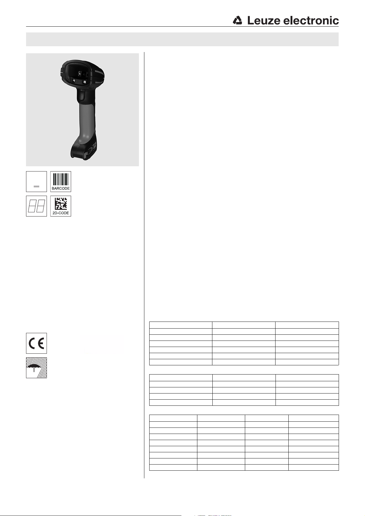
IT 1911i / IT 1981i 2D-code hand-held scanner with Bluetooth for industrial use
Dimensioned drawing
en 03-2015/09 50123747-02
Very sturdy hand-held scanner for
2D-codes and bar codes
Transmission to base station via Bluetooth
class 1 V2.1
Very large range with high resolution and
improved decoding
Robust trigger button
Acoustic signal, LED and vibration alarm
following successful reading
RS 232, USB and PS/2 interface
Operating temperature from -20°C through
50°C
Degree of protection IP 65
Accessories
TTL-RS 232 cable
Part no. 50114517
PS/2 cable
Part no. 50114519
USB cable, 3m
Part no. 50114521
USB helix cable, 5m
Part no. 50114523
Power supply unit for Base IT 19x1i
We reserve the right to make changes •
Part no. 50123862
Electrical connection
for RS 232 cable
9-pin Sub-D Signal Base for IT 19x1i RJ41
2TXD4
3RXD 5
5GND3
7CTS6
8RTS8
95VDC7
for USB cable
USB type A Signal Base for IT 19x1i RJ41
15VDC7
2Data -10
3Data +9
4GND3
for PS/2 cable
Mini DIN connector Mini DIN socket Signal Base for IT 19x1i RJ41
1-PC Data4
22NC
33GND3
445VDC7
5-PC Clock5
66NC
-1KB data8
-5KB clock6
IT 1911i / IT 1981i - 03
Page 2
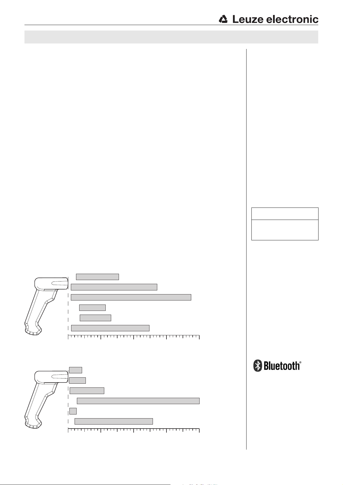
0 200 400 600100 300 500 700 800
7.5 Mil
(0.191 mm)
Code 39
PDF 417
Data Matrix
QR Code
UPC
13 Mil
(0.330 mm)
20 Mil
(0.508 mm)
6.7 Mil
(0.170 mm)
10 Mil
(0.254 mm)
20 Mil
(0.508 mm)
Code 39
IT 1911i ER-3
Typ. reading distance depending on the code module [mm]
0 4000 8000 120002000 6000 10000 14000 16000
7.5 Mil
(0.191 mm)
Code 39
Code 39
Data Matrix
Data Matrix
UPC
13 Mil
(0.330 mm)
20 Mil
(0.508 mm)
100 Mil
(2.540 mm)
10 Mil
(0.254 mm)
100 Mil
(2.540 mm)
Code 39
IT 1981i FR-3
Typ. reading distance depending on the code module [mm]
IT 1911i / IT 1981i
Specifications
Electrical data IT 19x1i … Base for IT 19x1i
Operating voltage U
Power consumption max. 5W @ 5V DC
B
3.7V DC internal battery 4.5 … 5.5VDC
Li-ion battery
Capacity 2,000mAh
Max. number of scans 50.000
Max. operating time 14h at 1 scan/s
Charging time at 9V DC 4.5h for complete charge following complete discharge
Radio transmission
Frequency 2.4 … 2.4835GHz (ISM band)
Typ. operating range 100m
Transmission speed up to 1Mbit/s
frequency hopping, Bluetooth ® V2.1, Class 1
Interfaces
Interface type RS 232, PS/2 and USB
Trigger via button or serial command
Types of codes
2D-codes Data Matrix ECC 200, MaxiCode, PDF417, MicroPDF, QR Code, Az-
Bar codes 2/5 Interleaved, Code 39, Code 128, Code 93, Codabar, UPC/EAN,
tec, Aztec Mesas, Code 49, EAN/UCC Composite
Codablock, GS1 Databar
Optical data
Optical system high-resolution pixel array 838x 640
Symbol contrast PCS 20% minimum
Light source integrated diffuse LED, wavelength 617nm ± 18nm
Read direction omnidirectional, various tilt and rotational angles up to 45°
Alignment aid laser pattern 630 … 680nm; IEC 60825-1:2007 Class 2
Mechanical data IT 19x1i… Base for IT 19x1i
Weight IT 1911i…: approx. 380g,
Dimensions 133 x 75 x 195mm 250 x 103 x 65mm
Shock resistance 50 falls from a height of 2m 50 falls from a height of 1.2 m
IT 1981i…: approx. 420g
290g (without cable)
Environmental data
Ambient temp. (operation) -20°C … +50°C -20 °C … +50 °C
Ambient temp. (storage) -40°C … +70°C -40 °C … +60 °C
Relative humidity 0 … 95 % (non-condensing) 0 … 95% (non-condensing)
Degree of protection IP 65 IP 51
Reading field
Tables
Remarks
Operate in accordance with
intended use!
The product may only be put into
operation by competent persons.
Only use the product in accor-
dance with the intended use.
Hand-held scanner with integrated decoder for high-contrast codes suitable for
industrial use.
Data transmission via configurable RS 232 interface.
Or keyboard-wedge operation via PS/2 or USB interface.
For a functional unit, an
IT 19x1i hand-held scanner
and a Base for IT 19x1i base
station as well as a power
supply unit and corresponding cable must be ordered.
IT 1911i / IT 1981i - 03 2015/09
Bluetooth is a trademark owned by
Bluetooth SIG, Inc., U.S.A. and
licensed to Honeywell.
Page 3

IT 1911i / IT 1981i 2D-code hand-held scanner with Bluetooth for industrial use
Order guide
2D-code hand-held scanner (Extended Range optics with large operating range) Part no.
IT 1911i ER-3 with Bluetooth data transmission 50122434
2D-code hand-held scanner (Full Range optics with very large operating range) Part no.
IT 1981i FR-3 with Bluetooth data transmission 50130495
Base station for 2D-code hand-held scanner with Bluetooth data transmission Part no.
Base for IT 19x1i with RS 232, PS/2 and USB interface 50122431
IT 1911i / IT 1981i - 03
Page 4
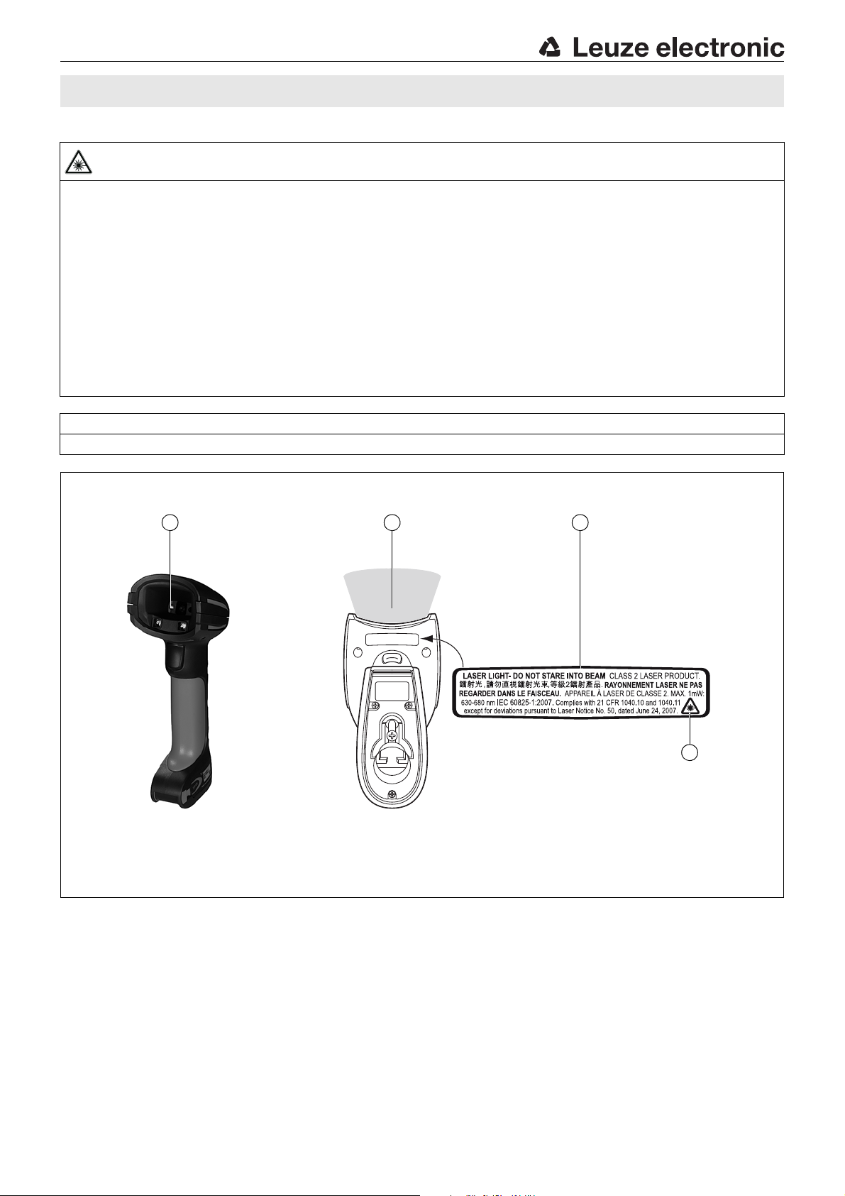
A Laser aperture
B Laser warning sign
C Laser information sign with laser parameters
A CA
B
IT 1911i / IT 1981i
Laser safety notices
ATTENTION, LASER RADIATION – LASER CLASS 2
Never look directly into the beam!
The device fulfills the EN 60825-1:2007 safety regulations for a product in laser class 2 as well as the U.S. 21 CFR 1040.10 regulations
with deviations corresponding to "Laser Notice No. 50" from June 24th, 2007.
Never look directly into the laser beam or in the direction of reflecting laser beams!
If you look into the beam path over a longer time period, there is a risk of injury to the retina.
Do not point the laser beam of the device at persons!
Interrupt the laser beam using a non-transparent, non-reflective object if the laser beam is accidentally directed towards a person.
When mounting and aligning the device, avoid reflections of the laser beam off reflective surfaces!
CAUTION! Use of controls or adjustments or performance of procedures other than specified herein may result in hazardous light
exposure.
Observe the applicable statutory and local laser protection regulations.
The device must not be tampered with and must not be changed in any way.
There are no user-serviceable parts inside the device.
Repairs must only be performed by Leuze electronic GmbH + Co. KG.
NOTICE
Laser information and warning signs firmly attached to the device.
IT 1911i / IT 1981i - 03 2015/09
Page 5

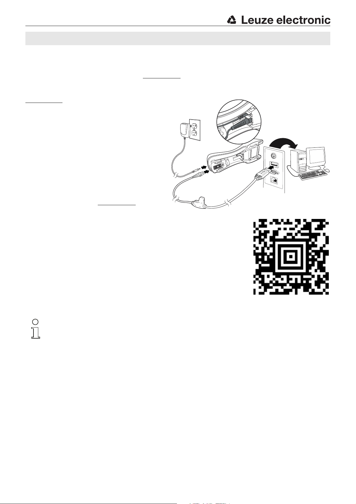
Connection for power
supply unit
Connection for interface
cable (RJ 41 socket)
IT 1911i / IT 1981i 2D-code hand-held scanner with Bluetooth for industrial use
Switching off the computer
Information on switching off and shutting down the connected computer - which must always be performed before connecting
peripheral devices, such as a scanner - can be found in the appropriate operating instructions for your computer.
Connecting the base station
Shown in the adjacent figure are the locations for installing the cables on
the base station. The individual installation steps are described in the following.
1.To secure the interface cable to the base station, proceed as follows:
plug the RJ 41 connector into the socket on the bottom of the base station until the cable clicks into place.
2.Connect the interface cable to the appropriate connection socket on
the computer.
3.You may need a power supply unit for supplying voltage if you would
like to charge the hand-held scanner via the base station or use an
RS 232 interface. Use the pin assignments (see "Electrical connection"
on page 1) to select the appropriate cable for your application.
4.Connect the power supply unit to the power socket.
5.Use the code for the respective application to configure the hand-held
scanner, see chapter "Parameterization".
6.Check the operational readiness of the scanner by pointing the scanning surface towards a flat surface and pulling the trigger. A red laser
pattern as well as the red illumination should now be visible. Now scan
a sample label.
The scanner emits an audible signal to confirm that the label has been
read; if necessary, the data are now passed on to the computer.
Notice!
To charge the hand-held scanner, the power supply unit must be plugged in
and the hand-held scanner placed in the base station.
Parameterization
The hand-held scanner can always be configured using bar codes. To do this, the bar code must first be selected on the package
insert and then the trigger actuated in order to read the code. The configuration is then immediately accepted and executed.
Several of the most important configurations are listed in the following.
A second option is to configure the hand-held scanner with the USB and RS 232 interfaces with the aid of the EZ Config PC
program. You can download and install this program from our homepage at www.leuze.com
The program can be used to make settings and transfer them to the hand-held scanner. The configuration can also be stored so
that it can be reused at a later time.
More information can also be found in the user's guide.
The standard applications are described and summarized below.
Notice!
Additional information on the device and short instructions can be found on the Internet at www.leuze.com.
.
IT 1911i / IT 1981i - 03
Page 6

IT 1911i / IT 1981i
Resetting the IT 1911i / IT 1981i to factory settings
To reset all parameters to factory settings, scan the adjacent
bar code.
Attention!
All settings are lost!!!
Return the hand-held scanner to the base station to apply the settings. This procedure is concluded with audible confirmation
signals.
You may then continue making settings or operation of the device.
Trigger
To activate the read process, a trigger signal is to be sent via the serial RS 232 interface or USB interface (COM port emulation
only). The command is to be sent at the set baud rate, parity, and data and stop bits.
The command for activation is: SYN T CR ASCII decimal values: 022; 084; 013
To cancel read readiness, send a deactivation.
The command for deactivation is: SYN U CR ASCII decimal values: 022; 085; 013
Following a successful read operation, the hand-held scanner deactivates itself.
The second option is activation via the built-in trigger button.
Configuration for the Leuze standard protocol
Scan the adjacent 2D-code.
The hand-held scanner is set to the following transmission parameters:
RS 232 transmission with 9,600 baud, 8 data bits, 1 stop bit, no parity, prefix <STX>,
postfixes <CR><LF>.
Return the hand-held scanner to the base station to apply the settings. This procedure
is concluded with audible confirmation signals.
Notice!
To charge the hand-held scanner, the power supply unit must be plugged in
and the hand-held scanner placed in the base station.
IT 1911i / IT 1981i - 03 2015/09
Page 7

IT 1911i / IT 1981i 2D-code hand-held scanner with Bluetooth for industrial use
Connecting the IT 1911i / IT 1981i to the serial PC interface
With TTL-RS232 cable (part no. 50114517)
Required parts:
1x IT 1911i ER-3 or IT 1981i FR-3
1x 50122431 Base for IT 19x1i
1x 50114517 KB 232-1 IT 190x
1x 50123862 Power supply unit for Base for
IT 19x1i
Notice!
Cable KB 232-1 IT190x (part no. 50114517)
uses TTL-level (0V…5 V) for data transmission.
As an alternative to this, cable KB 232-
2 IT190x (part no. 50115105) can be used.
This cable works with the regular RS232 level
(-12V…+12 V) and therefore features a higher
interference rejection. Both cables are connection compatible.
Procedure:
1.Switch off the PC.
2.Connect the interface cable to a free COM port
(RS 232) on the computer and to the base station.
3.Plug one end of the power supply unit cable into the
base station and the other end into a free power
socket.
4.Switch the PC back on.
5.Scan the adjacent bar code.
The hand-held scanner is set to the following transmission parameters:
RS 232 transmission with 115,200 baud, 8 data bits, 1 stop bit, no parity, postfixes <CR><LF>.
6.Return the hand-held scanner to the base station to apply the settings. This procedure is concluded with optical confirmation
signals (green LED on the base station).
7.If necessary, adjust the transmission parameters of the used COM port to those of the hand-held scanner.
Attention!
We recommend connecting the base station directly to a PC or to the MA 21 or MA 41… connection units. If connecting to other components, please note that a voltage level range of 0 … +5 V (TTL level) is maintained on the data lines!
Notice!
To charge the hand-held scanner, the power supply unit must be plugged in
and the hand-held scanner placed in the base station.
IT 1911i / IT 1981i - 03
Page 8

Connecting the IT 1911i / IT 1981i to the MA 2xxi
Required parts:
1x IT 1911i ER-3 or IT 1981i FR-3
1x 50122431 Base for IT 1911i
1x 50114517 KB 232-1 IT 190x
1x 50123862 Power supply unit for Base for IT 1911i
1x 50113397 KB JST-HS-300
1x MA 2xxi for the respective fieldbus system
Procedure:
1.Connect cable KB JST-HS-300 to the system connector on the MA 2xxi.
2.Connect the interface cable to cable KB JST-HS-300. Connect the interface cable and the
power supply unit to the base station (see "Connecting the IT 1911i / IT 1981i to the serial
PC interface").
3.Scan the adjacent 2D code.
The hand-held scanner is set to the following transmission parameters:
RS 232 transmission with 9,600 baud, 8 data bits, 1 stop bit, no parity, postfixes
<CR><LF>.
4.Return the hand-held scanner to the base station to apply the settings. This procedure is
concluded with audible confirmation signals.
IT 1911i / IT 1981i
Notice!
To charge the hand-held scanner, the power supply unit must be plugged in
and the hand-held scanner placed in the base station.
IT 1911i / IT 1981i - 03 2015/09
Page 9

IT 1911i / IT 1981i 2D-code hand-held scanner with Bluetooth for industrial use
Connecting the IT 1911i / IT 1981i to the MA 21
Required parts:
1x IT 1911i ER-3 or IT 1981i FR-3
1x 50122431 Base for IT 19x1i
1x 50114517 KB 232-1 IT 190x
1x 50123862 Power supply unit for Base for IT 19x1i
1x 50035421 KB 021 Z
1x 50030481 MA 21 100
Pin assignments KB021 Z:
Core color: Signal Terminal in the MA 21:
Brown (RXD) 26
White (TXD) 27
Blue (GND) 28
Red (VCC)
Black (GND)
Bare (shield) (PE) 21
Procedure:
1.Connect cable KB 021 Z to the MA 21… acc. to the above pin assignments.
2.Connect the interface cable to cable KB 021 Z. Connect the interface cable and the power
supply unit to the base station (see "Connecting the IT 1911i / IT 1981i to the serial PC interface").
3.Scan the adjacent 2D code.
The hand-held scanner is set to the following transmission parameters:
RS 232 transmission with 9,600 baud, 7 data bits, 1 stop bit, even parity, postfixes
<CR><LF>.
4.Return the hand-held scanner to the base station to apply the settings. This procedure is
concluded with audible confirmation signals.
Notice!
To charge the hand-held scanner, the power supply unit must be plugged in
and the hand-held scanner placed in the base station.
IT 1911i / IT 1981i - 03
Page 10

Disconnect
IT 1911i / IT 1981i
Connecting the IT 1911i / IT 1981i to the PS/2 interface
The operation of the hand-held scanner in keyboard emulation mode is described in this section. With this operating mode, a PC
keyboard is emulated. The read data are written directly into the currently activated program. The data can thereby be further
processed in all standard programs.
Required parts:
1x IT 1911i ER-3 or IT 1981i FR-3
1x 50122431 Base for IT 19x1i
1x 50123862 Power supply unit for Base for
IT 19x1i
1x 50114519 KB PS2-1 IT 19xx
Procedure:
1.Switch off the PC.
2.Disconnect the keyboard.
3.Connect the cable for the base station between the
keyboard and the PC.
4.Switch the PC back on.
5.Scan the 2D code shown below.
6.Return the hand-held scanner to the base station
to apply the settings. This procedure is concluded
with audible confirmation signals.
Notice!
To charge the hand-held scanner, the power supply unit must be plugged in
and the hand-held scanner placed in the base station.
IT 1911i / IT 1981i - 03 2015/09
Page 11

IT 1911i / IT 1981i 2D-code hand-held scanner with Bluetooth for industrial use
Connecting the IT 1911i / IT 1981i to the USB interface (keyboard emulation)
Operating the hand-held scanner in keyboard emulation mode on a USB port is described in this section. With this operating
mode, a PC keyboard is emulated. The read data is written directly into the currently activated program. The data can therefore
be further processed in all standard programs.
Required parts:
1x IT 1911i ER-3 or IT 1981i FR-3
1x 50122431 Base for IT 19x1i
1x 50123862 Power supply unit for Base for
IT 19x1i
1x 50114521 KB USB-1 IT190x (3m, straight)
or
1x 50114523 KB USB-2 IT190x (5m, spiral)
Procedure:
1.Connect the cable for the base station to a free USB
port.
2.The scanner acknowledges this connection with a beep.
3.Scan the adjacent 2D code.
4.Return the hand-held scanner to the base station to
apply the settings. This procedure is concluded with
audible confirmation signals.
Notice!
To charge the hand-held scanner, the power supply unit must be plugged in
and the hand-held scanner placed in the base station.
IT 1911i / IT 1981i - 03
Page 12
IT 1911i / IT 1981i
Connecting the IT 1911i / IT 1981i to the USB interface (COM port emulation)
The operation of the hand-held scanner as a serial interface on a USB port is described in this chapter. With this operating mode,
a COM interface is emulated. The read data are sent to a new COM interface. The drivers with which this COM interface is emulated can be downloaded from our homepage at www.leuze.com
expect data via COM interfaces.
Required parts:
1x IT 1911i ER-3 or IT 1981i FR-3
1x 50122431 Base for IT 19x1i
1x 50123862 Power supply unit for Base for
IT 19x1i
1x 50114521 KB USB-1 IT190x (3 m, straight)
or
1x 50114523 KB USB-2 IT190x (5 m, spiral)
Procedure:
1.Install the USB serial driver
(current version available at www.leuze.com
2.Connect the cable for the base station to a free USB
port.
3.The scanner acknowledges this connection with a beep.
4.Scan the adjacent 2D code.
5.Open a terminal program or your program for the serial
interface, select the new COM port, and make the following settings: baud rate 115,200, 8 data bits, 1 stop
bit, no parity, postfix <CR>.
6.Return the hand-held scanner to the base station to
apply the settings. This procedure is concluded with
audible confirmation signals.
).
. Thus, the data can be processed further in programs which
Notice!
To charge the hand-held scanner, the power supply unit must be plugged in
and the hand-held scanner placed in the base station.
IT 1911i / IT 1981i - 03 2015/09
 Loading...