

Page 1

IT 1911i
Industrial 2D-code hand-held scanner
with RF transmission
EN 50123793 2013/06
We reserve the right to
make technical changes
TECHNICAL DESCRIPTION
Page 2

© 2013
Leuze electronic GmbH + Co. KG
In der Braike 1
Page 3

Contents
1 Scope of delivery ............................................................................................................................... 5
1.1 IT 1911i xx-3 ........................................................................................................................................ 5
1.2 Base station IT 1911i ........................................................................................................................... 5
2 Installation ......................................................................................................................................... 6
2.1.1 Switching off the PC ............................................................................................................................ 6
2.2 Connecting the base station ................................................................................................................ 6
2.2.1 Connecting to base station IT 1911i .................................................................................................... 6
2.3 How do I scan codes? ......................................................................................................................... 7
2.3.1 Testing the scanner ............................................................................................................................. 7
3 Technical Data ................................................................................................................................... 8
3.1 Pin assignments of the connection cable ............................................................................................ 8
3.1.1 KB 232-1 IT 190x Part no. 50114517 ................................................................................................ 8
3.1.2 KB PS2-1 IT190x Part no. 50114519 ................................................................................................ 8
3.1.3 KB USB-1 IT 190x Part no. 50114521 .............................................................................................. 8
3.1.4 KB USB-2 IT 190x Part no. 50114523 .............................................................................................. 9
3.2 Reading fields ...................................................................................................................................... 9
4 Resetting the IT 1911i to factory settings ..................................................................................... 10
5 Configuration ................................................................................................................................... 11
5.1 IT 1911i to the serial PC interface ..................................................................................................... 12
5.1.1 With KB 232-1 IT190x Part no. 50114517 ...................................................................................... 12
5.1.2 Configuration for the Leuze standard protocol .................................................................................. 13
5.2 IT 1911i to MA 200i ........................................................................................................................... 14
5.2.1 Commissioning .................................................................................................................................. 14
5.3 IT 1911i to MA 21 .............................................................................................................................. 17
5.4 IT 1911i to PS2 interface ................................................................................................................... 19
5.5 IT 1911i to USB interface (keyboard emulation) ............................................................................... 20
5.6 IT 1911i to USB interface (COM port emulation) .............................................................................. 21
5.7 Activating the read process ............................................................................................................... 22
5.8 Configuration ..................................................................................................................................... 22
5.9 Troubleshooting ................................................................................................................................. 23
6 Type overv iew .................................................................................................................................. 24
7 Accessories/Spare parts ................................................................................................................ 25
7.1 Connecting to Leuze multiNet Plus ................................................................................................... 26
7.2 Connection to various fieldbuses using MA 200i .............................................................................. 26
Leuze electronic IT1911i 3
Page 4

8 Service and support ........................................................................................................................ 27
Leuze electronic IT1911i 4
Page 5

1 Scope of delivery
Type designation
Scanner
1.1 IT 1911i xx-3
1. Hand-held scanner IT 1911i
2. Rechargeable battery (installed)
3. Package insert
1.2 Base station IT 1911i
reading field
Laser notice
Information about
standards
1. Base station CCB02-100BT
An overview of the types can be found on page 24.
Information about
standards
For accessories, see page 25.
Leuze electronic IT1911i 5
Page 6

Connection for power supply unit
2 Installation
2.1.1 Switching off the PC
NOTICE
Make sure that the PC is switched off before connecting the scanner.
2.2 Connecting the base station
Shown in the figure below are the locations for installing the cable on the base station.
Connection for interface cable
2.2.1 Connecting to base station IT 1911i
1. To secure the connection cable to the base station, proceed as follows: Insert the RJ 41 connector into
the socket on the bottom of the base station until the cable clicks into place.
2. Connect the other end of the connection cable to the appropriate connection socket on the PC.
3. You may need a power supply unit for voltage supply if you would like to charge the hand-held scanner at
the base station or if you use an RS 232 interface. Use the pin assignments (see page 8) to select the
appropriate cable for your application.
4. Connect the power supply unit to the power socket.
5. Configure the hand-held scanner using the codes for the corresponding application; see chapter
"5 Configuration" or the external document "User’s Guide IT 1910i/1911i".
Leuze electronic IT1911i 6
Page 7
6. Check the operational readiness of the scanner by pointing the scanning surface towards a flat surface
and pulling the trigger. A green target line as well as the red illumination should now be visible. Now scan
a sample label. The scanner emits an audible signal to confirm that the label has been read; if necessary,
the data are now passed on to the PC.
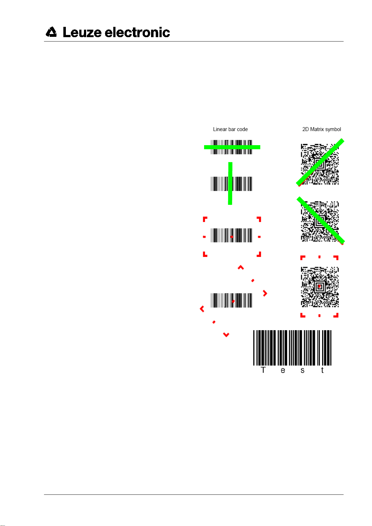
2.3 How do I scan codes?
This section explains the best way to scan codes:
The scanner must be held at a slight angle to the
bar code. (Do not hold the scanner at a right angle
to the bar code.)
The green LED line which serves as an alignment
aid should be positioned at the center of the code.
This ensures that the center point of the camera is
aligned with the code.
(The scanner will not be able to detect the label
correctly if it is not fully captured by the camera.)
The green LED line is smaller and narrower if the
scanner is held closer to the code. Small codes
should be read at a smaller reading distance. With
larger codes, the reading distance must be large
enough so that the camera can capture the
complete code.
2.3.1 Testing the scanner
The adjacent bar code can be used for testing the scanner, the module
size is 0.5 mm (20 mil)
Code 39 bar code sample
Leuze electronic IT1911i 7
Page 8

Pin number
Signal
Designation
1
nc
Not used
2
TX
Transmit data
3
RX
Receiving line / Receive Data
4
nc
Not used
5
GND
Ground connection
6
DTR
Data set ready (+5 volt connected to output)
7
CTS
Clear to send
8
RTS
Request to send
9
VCC IN
4.5 – 5.5 V DC (if no power supply unit is connected to the power supply unit
connection)
Pin
connector
Pin socket
Signal
Designation
1 - PC Data
PC data line
2 2 NC
Not used
3 3 GND
Ground connection
4 4 VCC IN
5 Volts DC
5 - PC Clock
PC clock line
6 6 NC
Not used
- 1 KB data
Keyboard data line
- 2 KB clock
Keyboard clock line
USB type A connector
Signal
Designation
1
VCC IN
5 Volts DC
2
Data -
Data line -
3
Data -
Data line +
4
GND
Ground connection
3 Technical Data
The technical data can be found in the data sheet for the IT 1911i.
3.1 Pin assignments of the connection cable
3.1.1 KB 232-1 IT 190x Part no. 50114517
Helix cable, maximum length 3 m. Signal level 0 and +5 volts TTL
Pin assignments of the 9-pin D-sub socket (female) for cable CBL-020-300-C00
For the suitable power supply unit for IT 190x (100 - 230 V/50 – 60 Hz), see chapter 7. The power supply unit
connection on the cable is not used.
3.1.2 KB PS2-1 IT190x Part no. 50114519
Helix cable, maximum length 3 m.
Pin assignments of the Mini DIN socket or connector for cable CBL-720-300-C00
3.1.3 KB USB-1 IT 190x Part no. 50114521
Straight cable, maximum length 3 m.
Pin assignments of USB type A connector for cable CBL-500-300-S00
Leuze electronic IT1911i 8
Page 9
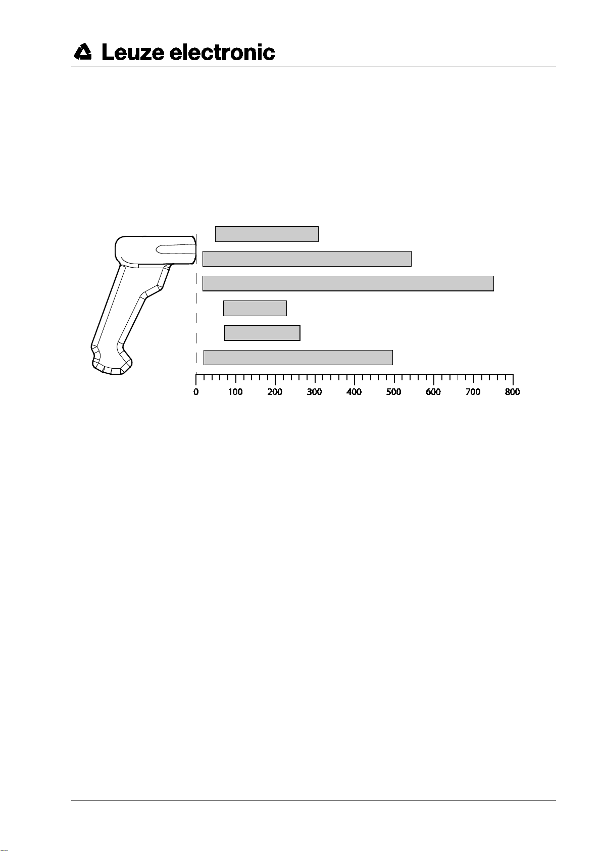
Code 39
5 mil
(0.127 mm)
UPC
13 mil
(0.330 mm)
Code 39
20 mil
(0.508 mm)
PDF
6.7 mil
(0.170 mm)
Data Matrix
10 mil
(0.254 mm)
QR Code
20 mil
(0.508 mm)
3.1.4 KB USB-2 IT 190x Part no. 50114523
Pin assignments of USB type A connector for cable CBL-500-500-C00:
as with part no. 50114521, but helix cable, maximum length 5 m.
3.2 Reading fields
IT 1911i ER-3
417
Typ. reading distance
1) Dependent on code module
1)
[mm]
Leuze electronic IT1911i 9
Page 10

4 Resetting the IT 1911i to factory sett i ngs
To reset all parameters to factory settings, scan the bar code shown below.
Attention!
All settings are lost!
Return the IT 1911i to the base station so that the settings can be accepted. Successful reading is confirmed
by an acoustic signal and the red LED on the base station going out briefly.
You may then continue making settings or operation of the device.
Leuze electronic IT1911i 10
Page 11

5 Configuration
Usually, bar codes are used to configure the hand-held scanner. Select the desired bar code and scan it
(see chapter 2.3). The configuration is then immediately accepted and executed.
A second option is to configure the hand-held scanner with the USB and RS 232 interfaces with the aid of the
VisualXpress PC program. You can download and install this program from our homepage at
www.leuze.com
configuration can also be stored so that it can be reused at a later time.
The standard applications are described and summarized below.
. The program can be used to make settings and transfer them to the hand-held scanner. The
Leuze electronic IT1911i 11
Page 12

5.1 IT 1911i to the serial PC interface
5.1.1 With KB 232-1 IT190x Part no. 50114517
For pin assignments, see chapter 3.1.1.
Please connect the base station for IT 1911i acc. to the adjacent figure.
Required parts:
1x 50122434 IT 1911i ER-3
1x 50122431 Base station IT 1911i
1x 50114517 KB 232-1 IT 190x
1x 50123862 Power supply unit
RS 232 transmission with 115200 baud, 8 data bits, 1 stop bit, no parity, suffix CR/LF.
Return the IT 1911i to the base station so that the settings can be accepted. Successful reading is confirmed
by an acoustic signal and the red LED on the base station going out briefly.
Leuze electronic IT1911i 12
Page 13

5.1.2 Configuration for the Leuze standard protocol
Leuze standard protocol:
RS 232 with 9600 baud, 8 data bits, 1 stop bit, no parity, prefix STX and suffix CR/LF
Factory settings
Return the IT 1911i to the base station so that the settings can be accepted. Successful reading is confirmed
by an acoustic signal and the red LED on the base station going out briefly.
To configure the device, please scan the codes in the specified order.
Successful reading is confirmed by an acoustic signal and the red LED on the base station going out briefly.
RS 232 baud rate: 9600
Prefix STX
Suffix CR/LF
Alternatively, the following Aztec configuration code can also be used:
The individual pieces of bar code information are
again provided in succession in the Aztec
configuration code.
Return the IT 1911i to the base station so that the
settings can be accepted. This procedure is
concluded with an acoustic signal.
Leuze electronic IT1911i 13
Page 14

5.2 IT 1911i to MA 200i
RS 232 transmission with 9600 baud, 8 data bits, 1 stop bit, no parity, suffix CR/LF.
Required parts:
1x 50122434 IT 1911i ER-3
1x 50122431 Base station IT 1911i
1x 50114517 KB 232-1 IT 190x
1x 50123862 Power supply unit
1x 50113397 KB JST-HS-300
1x 50112893 MA 204i Profibus gateway
or 50112892 MA 208i Ethernet gateway
or 50112891 MA 248i Profinet gateway
5.2.1 Commissioning
• Open the MA 200i
• Guide KB JST-HS-300 with the PG cable gland through the threaded hole and insert
the 12-pin JST connector
• Connect the base station with the RS 232 cable
• Connect the RS 232 cable to the 9-pin D-sub connector
• Set the address using the address switch
• Insert the field bus connection cable
• Apply the voltage supply.
Please connect the base station acc. to the following figure.
Leuze electronic IT1911i 14
Page 15
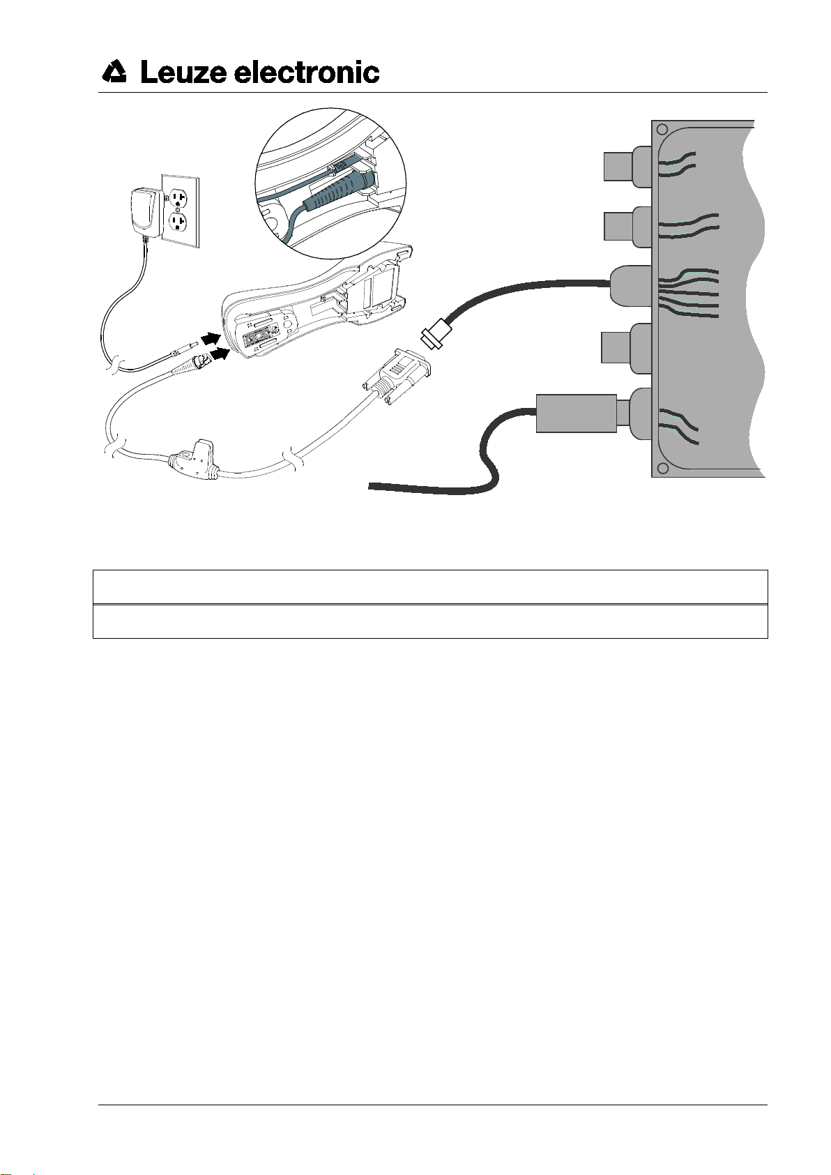
Base station for IT 1911i
KB JST-HS-300
approx. 0.3 m
9-pol. D-sub
18 to 30 V DC
Details on connecting the MA 200i can be found in "Technical description MA 200i".
NOTICE
You can find the configuration codes on the next page.
Leuze electronic IT1911i 15
Page 16

5.2.1.1 Configuration
Factory settings
Return the IT 1911i to the base station so that the settings can be accepted. This procedure is concluded with
an acoustic signal.
To configure the device, please scan the codes in the specified order.
Successful reading is confirmed by an acoustic signal and the red LED on the base station going out briefly.
RS 232 baud rate: 9600
Suffix CR/LF
Alternatively, the following Aztec configuration code can also be used:
The individual pieces of bar code information are
again provided in succession in the Aztec
configuration code.
Return the IT 1911i to the base station so that the
settings can be accepted. This procedure is
concluded with an acoustic signal.
Leuze electronic IT1911i 16
Page 17
Core color
Signal
Terminal assignments MA 21
brown
(RXD)
26
white
(TXD)
27
blue
(GND)
28
red
(VCC)
black
(GND)
bare (shield)
(PE)
21
5.3 IT 1911i to MA 21
RS 232 transmission with 9600 baud, 7 data bits, 1 stop bit, even parity, suffix CR/LF.
Required parts:
1x 50122434 IT 1911i ER-3
1x 50122431 Base station IT 1911i
1x 50114517 KB 232-1 IT190x
1x 50123862 Power supply unit
1x 50035421 KB 021 Z
1x 50030481 MA 21 100
5.3.1.1 Pin assignments KB021 Z
Leuze electronic IT1911i 17
Page 18

5.3.1.2 Configuration
Factory settings
Return the IT 1911i to the base station so that the settings can be accepted. This procedure is concluded with
an acoustic signal.
To configure the device, please scan the codes in the specified order.
Successful reading is confirmed by an acoustic signal and the red LED on the base station going out briefly.
RS 232 baud rate: 9600
7 data bits, even parity, 1 stop bit
Suffix CR/LF
Alternatively, the following Aztec configuration code can also be used:
The individual pieces of bar code information are
again provided in succession in the Aztec
configuration code.
Return the IT 1911i to the base station so that the
settings can be accepted. This procedure is
concluded with an acoustic signal.
Leuze electronic IT1911i 18
Page 19

Disconnect
5.4 IT 1911i to PS2 interface
The operation of the IT 1911i in keyboard-wedge mode is described in this chapter. A PC keyboard is
emulated in this operating mode. The data which are read in are written directly to the currently activated
program. Thus, the data can be processed further in all standard programs.
Required parts:
1x 50122434 IT 1911i ER-3
1x 50122431 Base station IT 1911i
1x 50114519 KB PS2-1 IT190x
1x 50123862 Power supply unit
Please connect the base station acc. to the figure below.
To do this, proceed as follows:
1. Switch off the PC.
2. Unplug the keyboard.
3. Connect the cable for the base station between
the keyboard and the PC.
4. Switch the PC back on.
5. Scan the code shown below.
NOTICE
To charge the IT 1911i, the power supply unit must be plugged
in and the hand-held scanner placed in the base station.
5.4.1.1 Configuration
PS2 keyboard emulation with CR LF
Return the IT 1911i to the base station so that the settings can be
accepted. This procedure is concluded with an acoustic signal.
Leuze electronic IT1911i 19
Page 20

5.5 IT 1911i to USB interface (keyboard emulation)
The operation of the IT 1911 in keyboard-wedge mode on a USB port is described in this chapter. A PC
keyboard is emulated in this operating mode. The data which are read in are written directly to the currently
activated program. Thus, the data can be processed further in all standard programs.
Required parts:
1x 50122434 IT 1911i ER-3
1x 50122431 Base station IT 1911i
1x 50114521 KB USB-1 IT190x or 50114523 KB USB-2 IT190x
1x 50123862 Power supply unit
Please connect the base station acc. to the figure below.
To do this, proceed as follows:
1. Connect the cable for the base station to a free
USB port.
2. The scanner acknowledges this connection with
an acoustic signal.
3. Scan the code shown below.
NOTICE
To charge the IT 1911i, the power supply unit must be
plugged in and the hand-held scanner placed in the
base station.
5.5.1.1 Configuration
USB keyboard emulation with CR LF
Return the IT 1911i to the base station so that the settings can be
accepted. This procedure is concluded with an acoustic signal.
Leuze electronic IT1911i 20
Page 21

5.6 IT 1911i to USB interface (COM port emulation)
The operation of the IT 1911i as a serial interface on a USB port is described in this chapter. A COM interface
is emulated in this operating mode. The data which are read in are sent to a new COM interface. The driver
with which you emulate this COM interface can be downloaded from our homepage at www.leuze.com
the data can be processed further in programs which expect data via COM interfaces.
Required parts:
1x 50122434 IT 1911i ER-3
1x 50122431 Base station IT 1911i
1x 50114521 KB USB-1 IT190x or 50114523 KB USB-2 IT190x
1x 50123862 Power supply unit
Please connect the base station acc. to the figures below.
To do this, proceed as follows:
1. Install the USB serial driver for the IT 1911i.
2. Connect the cable for the base station to a free USB
port.
. Thus,
3. The scanner acknowledges this connection with an
acoustic signal.
4. Scan the code shown below.
5. Open a terminal program or your program for the serial interface, select the new COM port, and make the
following settings: baud rate 115200, 8 data bits, 1 stop bit and no parity. A CR is transmitted as suffix (or
terminator).
NOTICE
To charge the IT 1911i, the power supply unit must be plugged in and the hand-held scanner placed in the
base station.
Leuze electronic IT1911i 21
Page 22

The activation command is:
SYN T CR
ASCII decimal values: 022; 084; 013
The deactivation command is:
SYN U CR
ASCII decimal values: 022; 085; 013
5.6.1.1 Configuration
COM port emulation on the next free COM address with 38400 baud,
8 data bits, 1 stop bit, no parity and a CR as suffix.
Return the IT 1911i to the base station so that the settings can be accepted. This procedure is concluded with
an acoustic signal.
5.7 Activating the read process
To activate the read process, a trigger signal is to be sent via the serial RS 232 interface or USB interface
(COM port emulation only). The command is to be sent at the set baud rate, parity, and data and stop bits.
To cancel read readiness, send a deactivation.
Following a successful read operation, the IT 1911i deactivates itself.
The second option is to use the trigger button to establish read readiness.
5.8 Configuration
Further details on configuration, such as parameters for code type release, number of digits, etc., can be
found in the User's Guide IT 1910i/1911i.
Leuze electronic IT1911i 22
Page 23

5.9 Troubleshooting
For problem detection and troubleshooting, examine your scanner as follows:
1. If the scanner is supplied with power via the connection cable, the scanner and PC must be connected to
each other before the scanner is commissioned. The PC must supply the scanner with 5 V DC. Check the
manual for your PC to ensure that the power supply is adequate for connecting your scanner.
2. Make certain that the connection cable is securely connected to the PC. You can find information on
properly connecting the scanner in the manual for your PC. Support is also available from your technical
staff.
3. If your system operates with an external voltage supply, make certain that the power supply unit is
properly connected to the scanner.
4. Check that the connection cable is securely connected to the base station. At the base station, please
loosen the cable using a small pin: the connector is unlocked.
5. If, even after performing all of these measures, the scanner is not ready for operation, replace the power
supply unit with a different recommended power supply unit which you are certain functions properly.
6. Make certain that your scanner's interface is compatible with the PC. Further information on this topic can
be found in the manual for your PC. Also check whether the scanner has been configured for the desired
application. This information is given in the User’s Guide IT 1910i/1911i.
7. Check whether the bar code labels which you would like to scan are of suitable quality and that the used
bar code type is recognized by your scanner. Damaged bar code labels (crinkled, torn or soiled) may be
recognized poorly or not at all by the scanner. If you suspect that the problem lies with the quality of the
label, check the read readiness with a label of relatively good quality.
8. If the problems are still not corrected, please contact the Leuze electronic hotline (see chapter 8).
Leuze electronic IT1911i 23
Page 24

IT series
Part no.
Designation
Interface
Figure
Industrial hand-held reader for bar codes and 2D-codes
Base station with communication and charging function
6 Type overview
50122434 IT 1911i ER-3 Bluetooth class 1
Bluetooth class 1
50122431 Base station for IT 1911i
All devices are supplied without cable. Cables must be ordered separately; see chapter "7 Accessories/Spare
parts".
PS2 / USB / TTL RS 232
Leuze electronic IT1911i 24
Page 25

IT
Base station for
IT
Length,
type
5V
cable and base station
7 Accessories/Spare parts
Accessories for IT series
Part no. Designation
50114519
50114521
50114523
50114517
50123862
50105384
KB PS2-1 IT 190x
PS2 cable for IT 190x
KB USB-1 IT 190x
USB cable for IT 190x
KB USB-2 IT 190x
USB cable for IT 190x
KB 232-1 IT 1900
RS 232 cable for IT 190x
NT Base IT 1911i
Voltage supply for the base
station (5 V DC), RS 232
Battery for IT 1911i, 3820,
4820 and IT 6320
3 m
spiral
3 m
straight
5 m
spiral
3 m
spiral
1.8 m
straight
3.7 V /
2000 mAh
P/N no. Figure
CBL-720-300-C00
CBL-500-300-S00
CBL-500-500-C00
CBL-020-300-C00
PS-05-1000W-C
100000495
1911i
- X
- X
- X
- X
- X
X -
1911i
BAT-Charger-4 Desk-EU
50114494
50120444 BT Wallholder HS65x8
50107034 Rope for IT3800i/4800/6300
Leuze electronic IT1911i 25
Charging station with power
supply unit for up to 4
batteries
2 x
1.5 m
straight
wall mount;
plastic
steel rope;
plastic
MB4-BATSCN01EUD0
11-66553-06R
ToolBalE
X -
X
X
Page 26

• MA 21 100
Interface converter / multiNet plus
Part no. 50030481
• KB 021 Z
Connection cable MA xx to IT 1911i
Part no. 50035421
• MA 204i
Profibus gateway
Part no. 50112893
or • MA 208i
Ethernet gateway
Part no. 50112892
or
• MA 248i
Profinet gateway
Part no. 50112891
• KB JST-HS-300
Connection cable MA xx to IT 1911i
Part no. 50113397
7.1 Connecting to Leuze multiNet Plus
7.2 Connection to various fieldbuses using MA 200i
Leuze electronic IT1911i 26
Page 27

Leuze electronic IT1911i 27
 Loading...