

Page 1
5 V
DC
IP 41IP 41
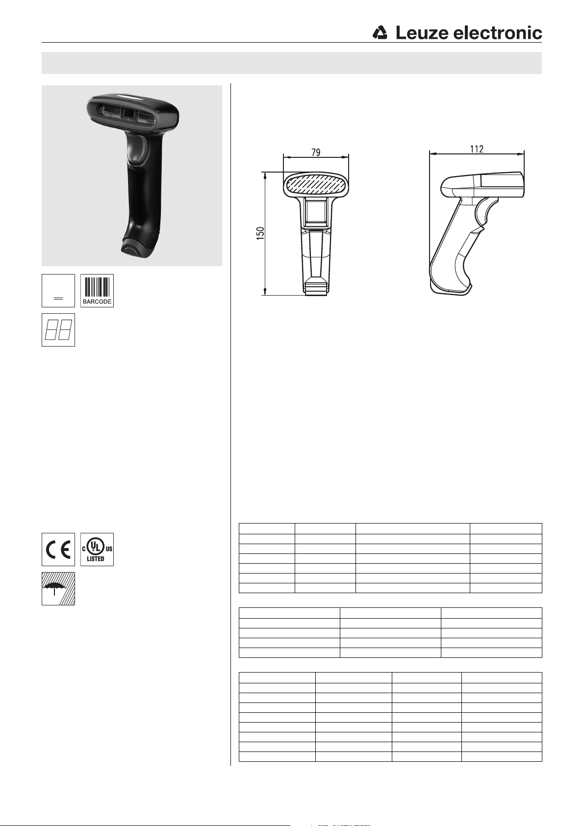
IT 1300g Hand-held bar code scanner
Dimensioned drawing
en 02-2014/07 50116932-01
Hand-held scanner for bar codes
Large reading field for the detection of
codes
Robust trigger button
Built-in decoder
Read-display
RS 232, USB and PS/2 interface
Operating temperature from 0 through 50°C
Protection class IP 41
Accessories
RS 232 cable
part no. 50115105
TTL-RS 232 cable
part no. 50114517
PS/2 cable
part no. 50114519
USB cable, 3m
part no. 50114521
USB helix cable, 5m
We reserve the right to make changes •
part no. 50114523
Power supply unit
part no. 50114525
Electrical connection
for RS 232 cable
9-pin Sub-D Signal Connection for power supply unit IT 1300g RJ41
2TXD 4
3RXD 5
5 GND external 3
7CTS 6
8RTS 8
9 5V DC internal 7
for USB cable
USB type A Signal IT 1300g RJ41
15VDC7
2Data -10
3Data +9
4GND3
for PS/2 cable
Mini DIN connector Mini DIN socket Signal IT 1300g RJ41
1-PC Data4
22NC
33GND3
445VDC7
5-PC Clock5
66NC
- 1 KB Data 8
-5KB Clock6
IT 1300g - 02
Page 2
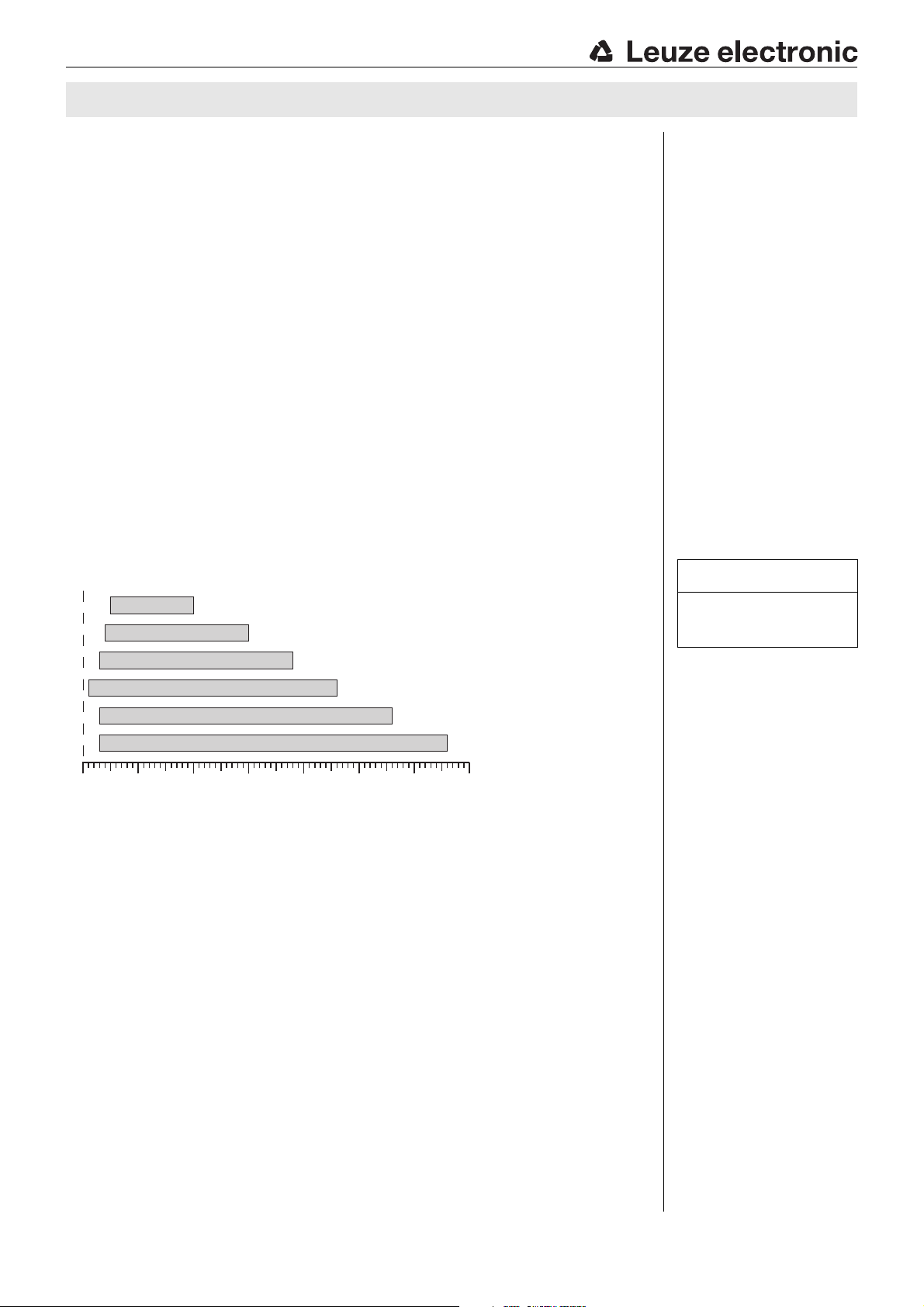
13 Mil
(0.330 mm)
5 Mil
(0.127 mm)
7,5 Mil
(0.190 mm)
10 Mil
(0.254 mm)
15 Mil
(0.381 mm)
20 Mil
(0.508 mm)
0 100 200 300 400 500 700600
Typ. read distance [mm]
dependent on the bar code module
IT 1300g
Specifications
Electrical data
Operating voltage U
Power consumption max. 1W
B
5VDC
Interfaces
Interface type RS 232, PS/2 and USB
Trigger via button or serial command
Code types
Bar codes 2/5 Interleaved, Code 39, Code 128, Code 93, Codabar,
UPC/EAN, GS1 Databar, Codablock
Optical data
Optical system 3648 linear Imager
Contrast 20% (black/white)
Light source integrated diffuse LED 630nm
Read distance 10 … 460mm (UPC 100%)
Read angle various tilt and rotational angles up to 65°
Mechanical data
Housing UL94V0 grade
Weight 160g (without cable)
Dimensions 150x 112x 79 mm
Shock resistance 50 falls from a height of 1.5m
Environmental data
Ambient temp. (operation) -0°C … +50 °C
Ambient temp. (storage) -40°C … +60°C
Relative air humidity 0 … 95% (non-condensing)
Protection class IP 41
Certifications IEC 60950-1 (US-20771-UL)
Reading field
IT 1300g
Tables
Remarks
Operate in accordance with
intended use!
The product may only be put into
operation by competent persons.
Only use the product in accor-
dance with the intended use.
Order guide
Hand-held scanner for bar codes (standard range) Part no.
IT 1300g-2 IT 1300g with RS 232, KBW and USB interface 50116864
IT 1300g - 02 2014/07
Ergonomically shaped handheld scanner with integrated
decoder for bar codes.
Data transmission via
confi^ktgurable RS 232
interface.
Or keyboard-wedge
operation via PS/2 or
USB interface.
Page 3
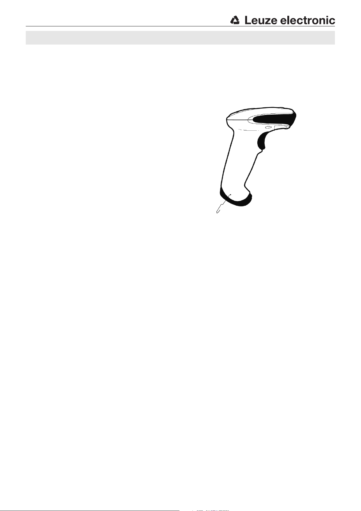
Cable latch
IT 1300g Hand-held bar code scanner
Switching off the computer
Information on switching off and shutting down the connected computer - which must always be performed before connecting
peripheral devices, such as a scanner - can be found in the appropriate operating instructions for your computer.
Connecting the IT 1300g
Shown in the adjacent figure are the individual steps for installing the
cable on the scanner; these steps are described in the following.
1.To secure the interface cable to the scanner, proceed as follows:
plug the RJ 41 connector into the socket on the bottom of the
hand-held scanner.
2.Connect the interface cable to the appropriate connection socket on
the computer.
3.You may need a power supply unit for supplying voltage; alternatively,
you can use a cable which supplies voltage from the computer system.
Use the pin assignments (see "Electrical connection" on page 1) to
select the appropriate cable for your application.
4.Connect the power supply unit to the power socket (not necessary if
voltage is supplied from the computer).
5.Use the code for the respective application to configure the hand-held
scanner, see chapter "Configuration".
6.Check the operational readiness of the scanner by pointing the
scanning surface towards a flat surface and pulling the trigger. A red
target line should now be visible. Now scan a sample label.
The scanner emits an audible signal to confirm that the label has been
read; if necessary, the data are now passed on to the computer.
IT 1300g - 02
Page 4
IT 1300g
Configuration
The hand-held scanner can always be configured using bar codes. To do this, the bar code must first be selected on the package
insert and then the trigger actuated in order to read the code. The configuration is then immediately accepted and executed.
Several of the most important configurations are listed in the following.
A second option is to configure the hand-held scanner with the USB and RS 232 interfaces with the aid of the EZ-Config PC
program. You can download and install this program from our homepage at www.leuze.de
The program can be used to make settings and transfer them to the hand-held scanner. The configuration can also be stored so
that it can be reused at a later time.
Further information on this can be found in the User's Guide for the IT 1300g.
The standard applications are described and summarised below.
Notice!
Additional information on the device and short instructions can be found on the Internet at www.leuze.de.
.
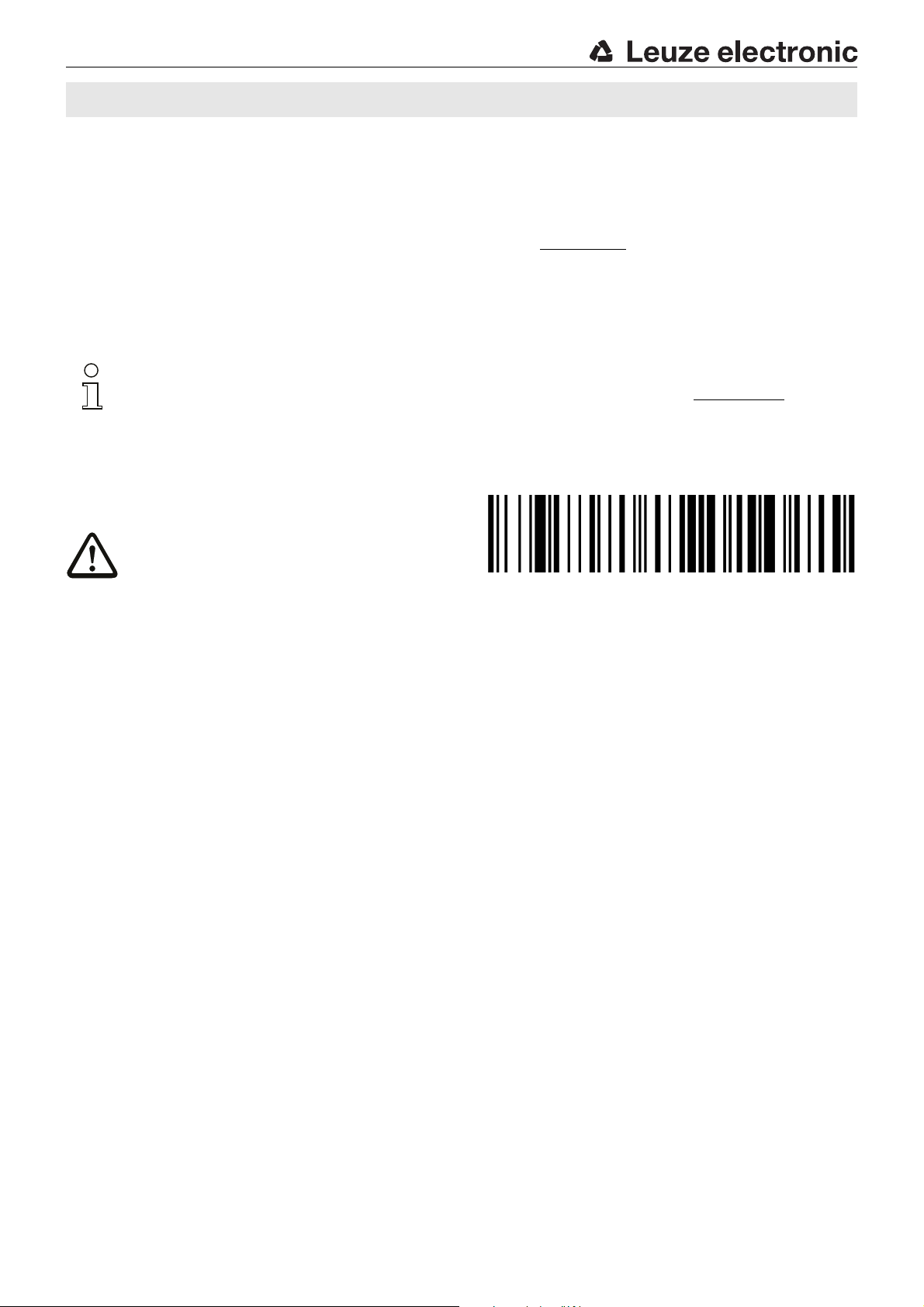
Resetting the IT 1300g to factory settings
To reset all parameters to factory settings, scan the adjacent
bar code.
Attention!
All settings are lost!!!
You may then continue making settings or operation of the device.
Trigger
To activate the read process, a trigger signal is to be sent via the serial RS 232 interface or USB interface (COM port emulation
only). The command is to be sent at the set baud rate, parity, and data and stop bits.
The command for activation is: SYN T CR ASCII decimal values: 022; 084; 013
To cancel read readiness, send a deactivation.
The command for deactivation is: SYN U CR ASCII decimal values: 022; 085; 013
Following a successful read operation, the IT 1300g deactivates itself.
The second option is activation via the built-in trigger button.
IT 1300g - 02 2014/07
Page 5
IT 1300g Hand-held bar code scanner
Configuration for the Leuze standard protocol
To set the Leuze standard protocol, you must first reset the scanner to factory settings and then individually define each of the
transmission parameters using a bar code
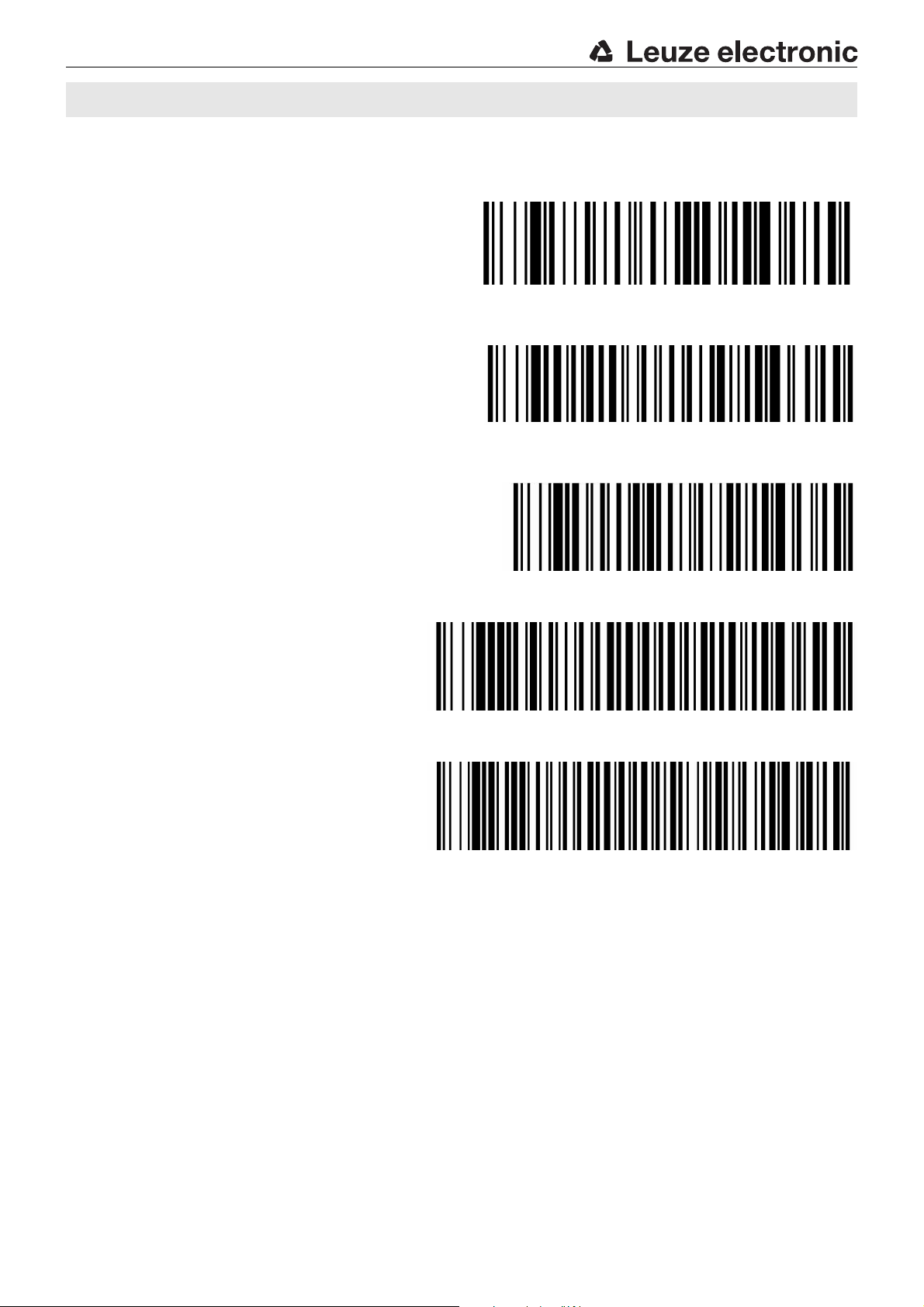
Procedure:
1.Scan the adjacent bar code.
The IT 1300g is reset to factory settings.
2.Successively scan the 4 bar codes shown below. Each read
operation is confirmed by a beep.
The IT 1300g is set to the following transmission parameters: RS 232 transmission with 9,600 baud, 8 data bits, 1 stop bit, no
parity, prefix <STX>, terminators <CR><LF>.
9600 Bd
Terminal ID
Prefix STX
Postfix CR/LF
IT 1300g - 02
Page 6

Connecting the IT 1300g to the serial interface
With voltage supply via PIN 9
required parts:
1x 50116864 IT 1300g-2
1x 50114517 TTL-RS 232 cable
With voltage supply via power supply unit
required parts:
1x 50116864 IT 1300g-2
1x 50114517 TTL-RS 232 cable
1x 50114525 Power supply unit
IT 1300g
Procedure:
1.Switch off the PC.
2.Connect the interface cable to a free COM port
(RS 232) on the computer, to the IT 1300g as well as to
the power supply unit.
3.Switch the PC back on.
4.Scan the adjacent bar code.
The IT 1300g is set to the following transmission
parameters:
RS 232 transmission with 9,600 baud, 8 data bits, 1 stop bit, no parity, terminators <CR><LF>.
5.If necessary, adjust the transmission parameters of the used COM port to those of the IT 1300g.
Attention!
We recommend connecting the IT 1300g directly to a PC or to the MA 21 or MA 41… connector units. If connecting
to other components, please note that a voltage level range of -12 … +12V is maintained on the data lines!
IT 1300g - 02 2014/07
Page 7

IT 1300g Hand-held bar code scanner
Connecting the IT 1300g to the MA 2xxi
required parts:
1x 50116864 IT 1300g-2
1x 50115105 RS 232 cable
1x 50113397 KB JST-HS-300
1x connector unit MA 2xxi for the corresponding fieldbus system:
50112893 MA 204i for PROFIBUS or
50112892 MA 208i for Ethernet or
50112891 MA 248i for PROFINET
Procedure:
1.Connect the KB JST-HS-300 cable to the MA 2xxi.
2.Connect the interface cable to cable KB JST-HS-300.
3.Scan the adjacent bar code.
The IT 1300g is reset to factory settings.
4.Successively scan the 3 bar codes shown below. Each read
operation is confirmed by a beep.
The IT 1300g is set to the following transmission parameters:
RS 232 transmission with 9,600 baud, 8 data bits, 1 stop bit, no parity, terminators <CR><LF>.
9600 Bd
Terminal ID
Postfix CR/LF
IT 1300g - 02
Page 8

Disconnect
IT 1300g
Connecting the IT 1300g to the PS/2 interface
The operation of the IT 1300g in keyboard emulation mode is described in this section. A PC keyboard is emulated in this
operating mode. The data which are read in are written directly to the currently activated program. Thus, the data can be
processed further in all standard programs.
required parts:
1x 50116864 IT 1300g-2
1x 50114519 PS/2 cable
Procedure:
1.Switch off the PC.
2.Disconnect the keyboard.
3.Plug in the IT 1300g hand-held scanner
between the keyboard and the PC.
4.Switch the PC back on.
5.Scan the bar codes shown below.
IBM PCs and compatible PCs, postfix
Keyboard layout for Germany/Austria
IT 1300g - 02 2014/07
Page 9

IT 1300g Hand-held bar code scanner
Connecting the IT 1300g to the USB interface (keyboard emulation)
The operation of the IT 1300g in keyboard-emulation mode on a USB port is described in this section. A PC keyboard is emulated
in this operating mode. The data which are read in are written directly to the currently activated program. Thus, the data can be
processed further in all standard programs.
required parts:
1x 50116864 IT 1300g-2
1x 50114521 KB USB-1 IT190x (3m, straight)
or
1x 50114523 KB USB-2 IT190x (5m, spiral)
Procedure:
1.Plug the IT 1300g hand-held scanner into a free USB
port.
2.The scanner acknowledges this connection with a beep.
3.Scan the bar codes shown below.
USB keyboard emulation with CR LF
Keyboard layout for Germany/Austria
IT 1300g - 02
Page 10

IT 1300g
Connecting the IT 1300g to the USB interface (COM-port emulation)
The operation of the IT 1300g as a serial interface on a USB port is described in this chapter. A COM interface is emulated in this
operating mode. The data which are read in are sent to a new COM interface. The driver with which you emulate this COM interface can be downloaded from our homepage at www.leuze.de
data via COM interfaces.
required parts:
1x 50116864 IT 1300g-2
1x 50114521 KB USB-1 IT190x (3 m, straight)
or
1x 50114523 KB USB-2 IT190x (5 m, spiral)
Procedure:
1.Install the USB serial driver
(current version at www.leuze.com
2.Plug the IT 1300g hand-held scanner into a free USB
port.
3.The scanner acknowledges this connection with a beep.
4.Scan the bar code shown below.
5.Open a terminal program or your program for the serial
interface, select the new COM port, and make the
following settings: baud rate 38,400, 8 data bits,
1 stop bit, no parity, terminator <CR>.
).
. Thus, the data can be processed further in programs which expect
USB COM-port emulation
IT 1300g - 02 2014/07
 Loading...