

Page 1
10 - 30 V
DC
4...20 mA
0...10
V
IP 67
IEC 60947...
IEC 60947...
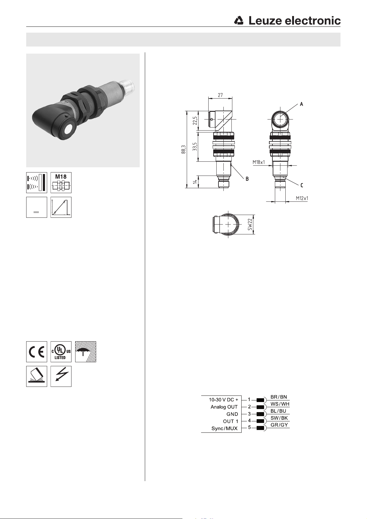
DMU318…W 90° angled ultrasonic sensors with analog and switching output
Dimensioned drawing
en 01-2017/02 50135824
50 … 400mm
150 … 1600mm
Function largely independent of surface
properties, ideal for detection of liquids,
bulk materials, transparent media, …
Sound exit less than 90° to the longitudinal
axis
Small dead zone at long scanning range
1 analog output 0 … 10V or 4 … 20mA
1 switching output (PNP or NPN)
NO/NC function reversible
NEW – Both outputs can easily be taught
using a button
NEW – Stable plastic design
NEW – Temperature-compensated
scanning range
Accessories:
(available separately)
Mounting systems
Mounting adapter M18-M30:
BTX-D18M-D30 (Part no. 50125860)
Cables with M12 connector
(KD …)
A Active sensor surface
B Teach-in button
C Indicator diodes
Electrical connection
We reserve the right to make changes • PAL_DMU318_400W_1600W_en_50135824.fm
Leuze electronic GmbH + Co. KG In der Braike 1 D-73277 Owen
DMU318-400.W…-M12 - 01
DMU318-1600.W…-M12 - 01
Page 2
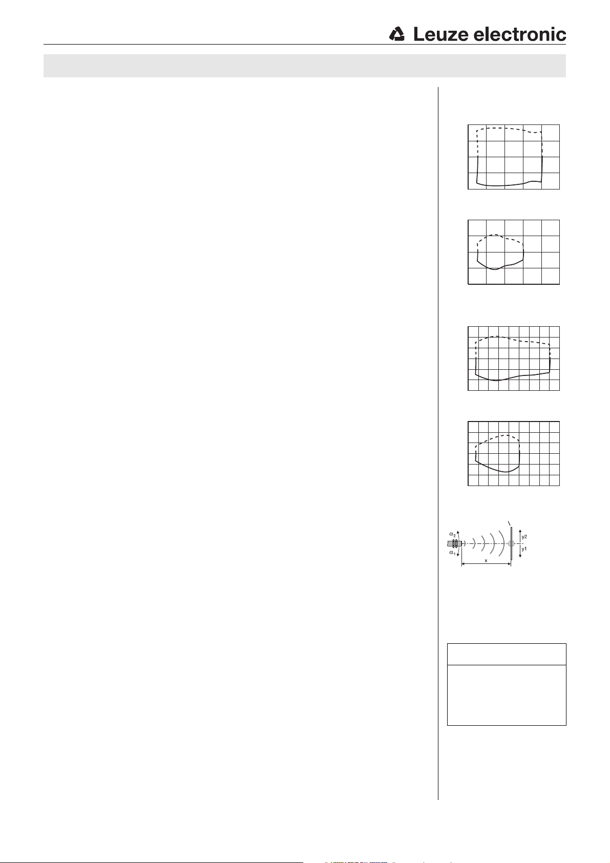
Object distance x [mm]
Width y of the sound cone [mm]
Typ. response behavior (plate 200x 200mm)
-100
-50
0
50
100
0 100 200 300 400 500
y1
y2
Object distance x [mm]
Width y of the sound cone [mm]
Typ. response behavior (rod Ø 25 mm)
y1
y2
-300
-200
0
100
-100
200
300
0 400 800 16001200
Object distance x [mm]
Width y of the sound cone [mm]
Typ. response behavior (plate 200x 200mm)
y1
y2
-300
-200
0
100
-100
200
300
0 400 800 16001200
Object distance x [mm]
Width y of the sound cone [mm]
Typ. response behavior (rod Ø 25 mm)
Object distance [mm]
Target (fixed):
plate or rod
Sound cone
= f (α,x)
DMU318…W
Technical data
Ultrasonic specifications DMU318-400.W3/…-M12 DMU318-1600.W3/…-M12
Scanning range
Adjustment range 50 … 400mm 150 … 1600mm
Ultrasonic frequency 300kHz 230kHz
Typ. opening angle 8° 8°
Resolution <2mm <2mm
Direction of beam 90° to longitudinal axis 90° to longitudinal axis
Reproducibility ± 0.5%
Switching hysteresis 1% 3) 1%
Analog output accuracy 1%
Temperature drift ≤ 5%
Timing
Switching frequency 10Hz 2Hz
Response time 500ms 500ms
Readiness delay < 900ms (analog output),
Electrical data
Operating voltage U
Residual ripple ± 7% of U
Open-circuit current ≤ 50mA
Analog output
Analog output …/…C…
Load resistance Current output: R
Characteristic curve adjustment 1-point teach: teach in button 2 … 7s,
Analog output error signal Distance too small: approx. 3.8 mA,
Switching output
Switching output / Function …/4… 1 PNP transistor switching output
Output current Max. 100 mA
Switching range adjustment 1-point teach: teach-in button 2 … 7s,
Changeover NO/NC Teach-in button > 12s
Indicators
Yellow LED OUT2: object detected
Blue LED Analog OUT: object detected
Yellow/green or blue/green LED flashing Teach-in / teaching error
Green LED Object within the scanning range
Mechanical data
Housing Plastic (PBT)
Active surface Epoxy resin, glass fiber reinforced
Weight 75g
Ultrasonic transducer Piezoceramic
Connection type M 12 connector, 5-pin
Fitting position Any
Environmental data
Ambient temp. (operation/storage) -20° … +70°C/-20° … +70°C
Protective circuit
VDE protection class III
Degree of protection IP 67
Standards applied EN 60947-5-2
Certifications UL 508, CSA C22.2 No.14-13
1) At 20°C
2) Target: 200mm x 200 mm plate
3) From end value
4) Over the temperature range -20°C … +70°C
5) For UL applications: use is permitted exclusively in Class 2 circuits according to NEC
6) The ceramic material of the ultrasonic transducer contains lead zirconium titanate (PZT)
7) 1=short-circuit and overload protection, 2=polarity reversal protection, 3=wire break and inductive protection
8) These proximity switches shall be used with UL Listed Cable assemblies rated 30V, 0.5 A min,
in the field installation, or equivalent (categories: CYJV/CYJV7 or PVVA/PVVA7)
1)
50 … 400mm 2)
1) 3)
3)
1%
4)
150 … 1600mm 2)
±0.5% 1)
≤ 5% 4)
3)
3)
3)
< 900ms (analog output),
< 500ms (switching output)
5)
B
…/…V…
10 … 30V DC (incl. ± 7% residual ripple)
B
1 analog output 4 … 20mA
1 analog output 0 … 10V
Voltage output: RL≥ 2kΩ
2-point teach: teach in button 7 … 12s,
Characteristic curve inversion: teach in button > 12s
≤ 500 Ω,
L
< 500ms (switching output)
Distance too large: approx. 11V / approx. 21mA
OUT 1 (pin 4): NO contact preset
…/2… 1 NPN transistor switching output
OUT 1 (pin 4): NO contact preset
2-point teach: teach-in button 7 … 12s
6)
7)
1, 2, 3
5) 8)
Diagrams
DMU318-400.W3/…-M12
100
50
0
-50
-100
0 100 200 300 400 500
DMU318-1600.W3/…-M12
y2
y1
Notes
Observe intended use!
This product is not a safety sensor
and is not intended as personnel
protection.
The product may only be put into
operation by competent persons.
Only use the product in accor-
dance with its intended use.
DMU318-400.W…-M12 - 01 2017/02
DMU318-1600.W…-M12 - 01
Page 3
DMU318…W 90° angled ultrasonic sensors with analog and switching output
Part number code
DMU318-1600 .W3 /4VK-M12
Operating principle
HTU Ultrasonic sensor, scanning principle, with background suppression
DMU Ultrasonic sensor, distance measurement
RKU Ultrasonic sensor, retro-reflective ultrasonic sensor
Series
318 318 series, cylindrical short M18 design
Scanning range in mm
400 50 … 400
1600 150 … 1600
Equipment
W Design with 90° angled head
3 Teach button on the sensor
Pin assignment of connector pin 4 / black cable wire (OUT1)
4 PNP output, NO contact preset
P PNP output, NC contact preset
2 NPN output, NO contact preset
N NPN output, NC contact preset
Pin assignment of connector pin 2 / white cable wire (Analog OUT/OUT2)
4 PNP output, NO contact preset
P PNP output, NC contact preset
2 NPN output, NO contact preset
N NPN output, NC contact preset
C Analog output 4 … 20 mA
V Analog output 0 … 10 V
Pin assignment of connector pin 5 / gray cable wire (Sync / MUX)
K Synchronization/multiplex input
Connection technology
M12 M12 connector, 5-pin
Order guide
The sensors listed here are preferred types; current information at www.leuze.com.
Designation Part no.
Scanning range / switching output / analog output / teach-in / design
50 … 400mm / PNP / current output 4 … 20mA / teach button / with 90° angled head DMU318-400.W3/4CK-M12 50136102
50 … 400mm / PNP / voltage output 0 … 10V / teach button / with 90° angled head DMU318-400.W3/4VK-M12 50136100
50 … 400mm / NPN / current output 4 … 20mA / teach button / with 90° angled head DMU318-400.W3/2CK-M12 50136103
50 … 400mm / NPN / voltage output 0 … 10V / teach button / with 90° angled head DMU318-400.W3/2VK-M12 50136101
150 … 1600mm / PNP / current output 4 … 20mA / teach button / with 90° angled head DMU318-1600.W3/4CK-M12 50136108
150 … 1600mm / PNP / voltage output 0 … 10V / teach button / with 90° angled head DMU318-1600.W3/4VK-M12 50136106
150 … 1600mm / NPN / current output 4 … 20mA / teach button / with 90° angled head DMU318-1600.W3/2CK-M12 50136109
150 … 1600mm / NPN / voltage output 0 … 10V / teach button / with 90° angled head DMU318-1600.W3/2VK-M12 50136107
Leuze electronic GmbH + Co. KG In der Braike 1 D-73277 Owen DMU318-400.W…-M12 - 01
DMU318-1600.W…-M12 - 01
Page 4
Dead zone
Sensor
OUT1 active
Yellow LED ON
Green LED OFF
OUT1 not active
Yellow LED OFF
Green LED ON
Distance
Hysteresis
Switching point
Scanning range
OUT1 not active
Yellow LED OFF
Green LED OFF
OUT1 not active
Yellow LED OFF
Green LED OFF
Dead zone
Sensor
OUT1 not active
Yellow LED OFF
Green LED ON
OUT1 active
Yellow LED ON
Green LED OFF
Distance
Hysteresis
Switching point
Scanning range
OUT1 active
Yellow LED ON
Green LED OFF
OUT1 active
Yellow LED ON
Green LED OFF
Dead zone
Sensor
OUT1 active
Yellow LED ON
Green LED OFF
OUT1 not active
Yellow LED OFF
Green LED ON
Distance
Hysteresis
Scanning range
OUT1 not active
Yellow LED OFF
Green LED OFF
OUT1 not active
Yellow LED OFF
Green LED OFF
Hysteresis
OUT1 not active
Yellow LED OFF
Green LED ON
Switching point 1 Switching
point 2
Dead zone
Sensor
OUT1 active
Yellow LED ON
Green LED OFF
OUT1 not active
Yellow LED OFF
Green LED ON
Distance
Hysteresis
Scanning range
OUT1 active
Yellow LED ON
Green LED OFF
OUT1 active
Yellow LED ON
Green LED OFF
Hysteresis
Switching point 1 Switching
point 2
OUT1 active
Yellow LED ON
Green LED OFF
DMU318…W
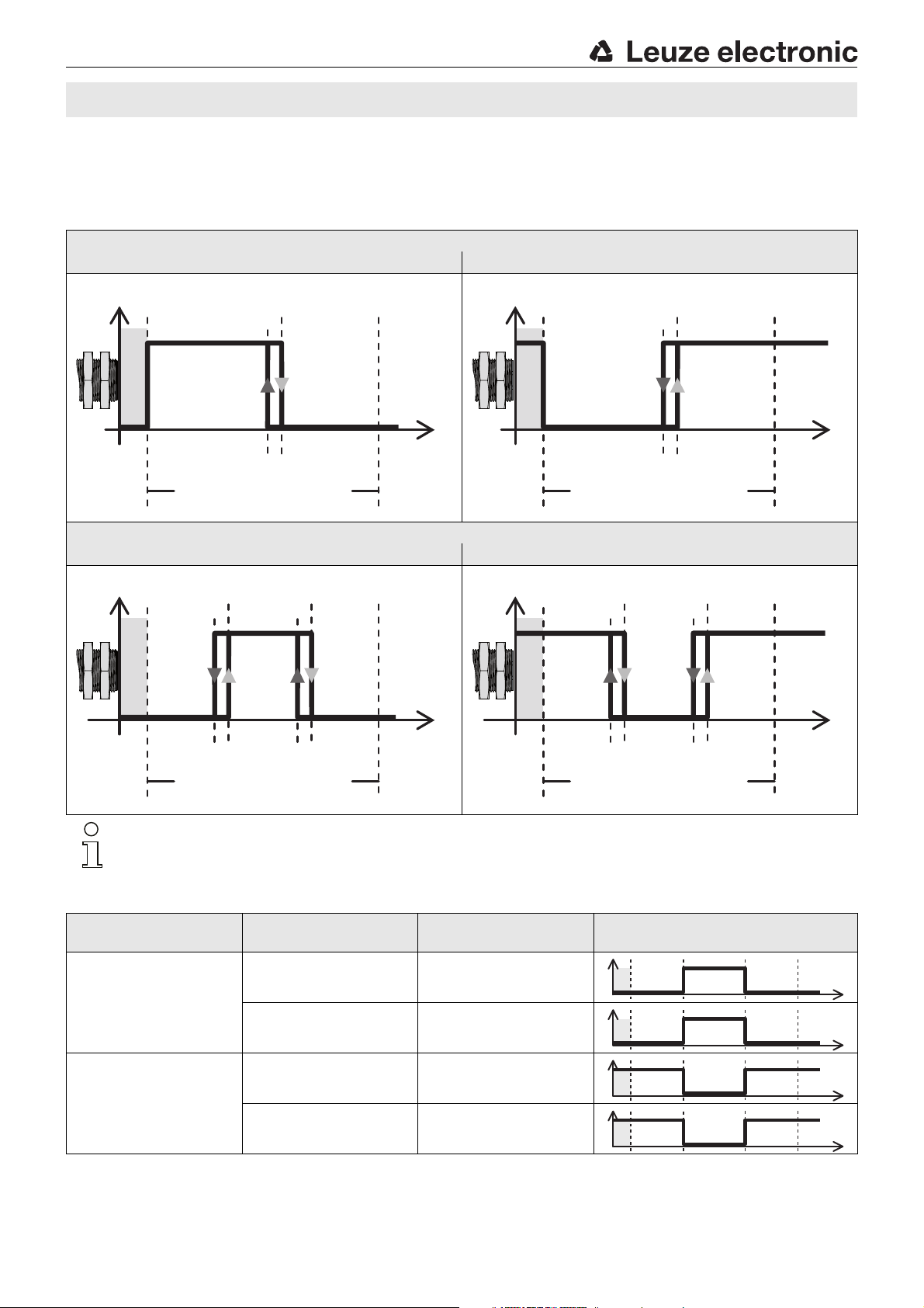
Device functions and indicators – switching output
The sensor has a button for setting switching output OUT1 and analog output Analog OUT. Use the teach button to perform the
1-point teach, the 2-point window-teach and to changeover the switching function (NO contact/NC contact). Device status and switching
states for OUT1 are indicated as follows by means of a yellow LED:
Switching output OUT1
1-point teach (1 switching point)
Switching behavior NO contact Switching behavior NC contact
2-point window-teach (2 switching points)
Switching behavior NO contact Switching behavior NC contact
Note!
The switching behavior is not defined in the dead zone.
Switching behavior with 2-point window-teach as a function of the switching function
Switching function
configured as
First taught object
distance
Second taught object
distance
Output switching behavior
Close Far
NO (normally open)
Far Close
Close Far
NC (normally closed)
Far Close
DMU318-400.W…-M12 - 01 2017/02
DMU318-1600.W…-M12 - 01
Page 5
DMU318…W 90° angled ultrasonic sensors with analog and switching output
Adjusting the switching points via the teach button
The switching point of the sensor is set to 400mm or 1600mm (static 1-point teach) on delivery.
By means of a simple operating procedure, the switching point for the output OUT1 can be individually taught to an arbitrary distance
within the scanning range with 1-point teach (static) or 2-point window-teach (static).
Moreover, the output function can be switched from NO contact (NO - normally open) to NC contact (NC - normally closed).
Selecting the output that is to be taught: OUT1 or Analog OUT
1.Press the teach button for ≥2s to activate teach mode. The yellow LED (OUT 1) flashes at 1Hz.
While in this state, output OUT 1 can be taught.
2.To teach output Analog OUT, briefly press the teach button again. The blue LED (Analog OUT) now flashes at 1Hz.
While in this state, output Analog OUT can be taught.
3.Briefly press the teach button again to toggle between outputs OUT 1 and Analog OUT in this state. The flashing LED indicates
which output is ready for teaching:
yellow LED flashing = OUT 1 ready for teaching,
blue LED flashing = Analog OUT ready for teaching.
Teaching output OUT 1
First activate the previously described teach mode for output OUT 1.
1-point teach (static) 2-point window-teach (static)
1. Place object at desired switching distance. 1. First, place object at desired switching distance for switching point 1.
2. To adjust the output OUT1, press the teach button for 2…7s until the
yellow LED flashes at 3Hz.
3. Release the teach button to complete the teach event.
The current object distance has been taught as the new switching point.
4. Error-free teach: LED states and switching behavior according to the
diagram shown above.
Faulty teach (object may be too close or too far away – please note scanning range):
green and yellow LEDs flash at 8Hz until an error-free teach event is
performed.
The affected output is inactive as long as there is a teaching error.
1) See table "Switching behavior with 2-point window-teach as a function of the switching function"
2. To adjust the output OUT1, press the teach button for 7…12s until the
yellow and green LEDs flash alternately at 3Hz.
3. Release the button. The sensor remains in teach mode and the LEDs
continue to flash.
4. Then, place the object at the desired switching distance for switching
point 2.
Note:The minimum distance between the switching points is a s fo llo ws:
5. Briefly press the teach button again to complete the teach event.
The switching window was taught in.
6. Error-free teach: LED states and switching behavior according to the
diagram shown above.
Faulty teach (object may be too close or too far away – please note scanning range):
green and yellow LEDs flash at 8Hz until an error-free teach event is
performed.
scanning range of 400 mm:40mm
scanning range of 1600mm:160mm
1)
Leuze electronic GmbH + Co. KG In der Braike 1 D-73277 Owen DMU318-400.W…-M12 - 01
DMU318-1600.W…-M12 - 01
Page 6
DMU318…W
Adjusting the switching function (NC/NO) via the teach button
The switching function of the sensor is preset as follows on delivery:
OUT 1: NO contact
The output function can be switched from NO contact (NO - normally open) to NC contact (NC - normally closed) and vice versa. If the
switching function is changed, the switching output is changed to the opposite state (toggled).
First activate the previously described teach mode for output OUT 1.
Changeover of the switching function
1. To change the switching function of output OUT 1, press the teach button for longer than 12s.
The current state of output OUT 1 is frozen during the adjustment process.
2. The green and yellow LEDs flash alternately at 3Hz.
If the yellow LED is ON afterwards, output OUT 1 functions as a normally open contact (NO).
If the yellow LED is OFF afterwards, output OUT 1 functions as a normally closed contact (NC).
DMU318-400.W…-M12 - 01 2017/02
DMU318-1600.W…-M12 - 01
Page 7
Dead zone
Sensor
Error
Approx.
11V
Approx.
21mA
Start point
0V
4mA
Object distance
Remote error:
Object outside of
the measurement range
Error
Approx.
3.8mA
End point
10V
20mA
Measurement range
Close error:
Object outside of
the measurement range
Object within measurement range
Blue LED ON
Dead zone
Sensor
Object distance
Error
Approx.
11V
Approx.
21mA
Error
Approx.
3.8mA
Remote error:
Object outside of
the measurement range
Close error:
Object outside of
the measurement range
Start point
10V
20mA
End point
0V
4mA
Measurement range
Object within measurement range
Blue LED ON
DMU318…W 90° angled ultrasonic sensors with analog and switching output
Device functions – analog output
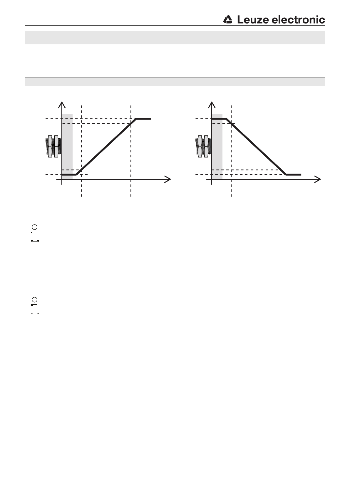
In measurement operation, the blue LED displays the behavior of analog output Analog OUT.
Analog output Analog OUT
Rising characteristic curve Falling characteristic curve
Note!
When setting the analog output (teach) via the teach button, one rising characteristic curve is always taught; with
2-point teach, independent of the selected object distances near/far. The characteristic output curve can be inverted,
however.
Adjusting the analog output via the teach button
On delivery, the characteristic output curve of the sensor is set as a rising characteristic curve with spread over the entire scanning range:
4 … 20mA or 0 … 10V corresponds to an object distance of 50 … 400mm or 150 … 1600mm, respectively.
The analog output can be set by means of 1-point teach or 2-point teach.
Note!
When setting the analog output (teach) via the teach input, one rising characteristic curve is always taught; with 2-point
teach, independent of the selected object distances near/far. The characteristic output curve can be inverted, however.
Selecting the output that is to be taught: OUT1 or Analog OUT
1.Press the teach button for ≥2s to activate teach mode. The yellow LED (OUT 1) flashes at 1Hz.
While in this state, output OUT 1 can be taught.
2.To teach output Analog OUT, briefly press the teach button again. The blue LED (Analog OUT) now flashes at 1Hz.
While in this state, output Analog OUT can be taught.
3.Briefly press the teach button again to toggle between outputs OUT 1 and Analog OUT in this state. The flashing LED indicates
which output is ready for teaching:
yellow LED flashing = OUT 1 ready for teaching,
blue LED flashing = Analog OUT ready for teaching.
Leuze electronic GmbH + Co. KG In der Braike 1 D-73277 Owen DMU318-400.W…-M12 - 01
DMU318-1600.W…-M12 - 01
Page 8
DMU318…W
1-point teach of the analog output
First activate the previously described teach mode for output Analog OUT.
By selecting an object distance within the scanning range, the characteristic curve of the analog output can be adjusted.
If an object is located outside of the taught measurement range, an error signal is output. A different analog signal is output here by the
sensor for the errors "distance too close: object outside of the measurement range" and "distance too far: object outside of the
measurement range".
1-point teach - rising characteristic curve
1. Place object at desired distance for the end point of the measurement range.
Note:The minimum object distance for the end of the measurement range is as follows:
2. To adjust analog output Analog OUT, press the teach button for 2…7s
until the blue and green LEDs flash simultaneously at 3Hz.
3. Release the button. The characteristic curve with plot rising from the start of the range (50 mm or 150 mm) to the set object distance was taught in.
4. Error-free teach: LED states acc. to "Technical data" -> "Indicators".
Faulty teach: green and blue LEDs flash at 8Hz until an error-free teach is performed.
2-point teach of the analog output
First activate the previously described teach mode for output Analog OUT.
By selecting 2 object distances within the scanning range, the characteristic curve of the analog output can be adjusted.
If an object is located outside of the taught measurement range, an error signal is output. A different analog signal is output here by the
sensor for the errors "distance too close: object outside of the measurement range" and "distance too far: object outside of the
measurement range".
scanning range of 400mm:90 mm
scanning range of 1600mm:310 mm
2-point teach - rising characteristic curve
1. Position the object at the first desired distance (near or far).
2. To adjust analog output Analog OUT, press the teach button for 7 … 12s until the blue and green LEDs flash alternately at 3Hz.
3. Release the button. The sensor remains in teach mode and the LEDs continue to flash.
4. Then position the object at the second desired distance (far or near).
Note:the minimum object distance between the start and end point of the measurement range
5. Briefly press the teach button again to complete the teach event.
The characteristic curve with rising plot from the near to the far object distance was taught in.
6. Error-free teach: LED states acc. to "Technical data" -> "Indicators".
Faulty teach: green and blue LEDs flash at 8Hz until an error-free teach is performed.
for a scanning range of 400mm is:40mm
for a scanning range of 1600mm is:160mm
Inverting the analog output (falling/rising characteristic curve)
First activate the previously described teach mode for output Analog OUT.
The characteristic curve of the analog output can be inverted, e.g., if a falling characteristic output curve is desired.
Inverting the characteristic curve
1. To invert the characteristic curve of the analog output Analog OUT, press the teach button for >12s until the blue and green LEDs flash alternately.
2. Release the button. The characteristic curve plot was inverted.
The blue LED indicates the current setting of the analog output:
ON = rising characteristic curve
OFF = falling characteristic curve
DMU318-400.W…-M12 - 01 2017/02
DMU318-1600.W…-M12 - 01
Page 9
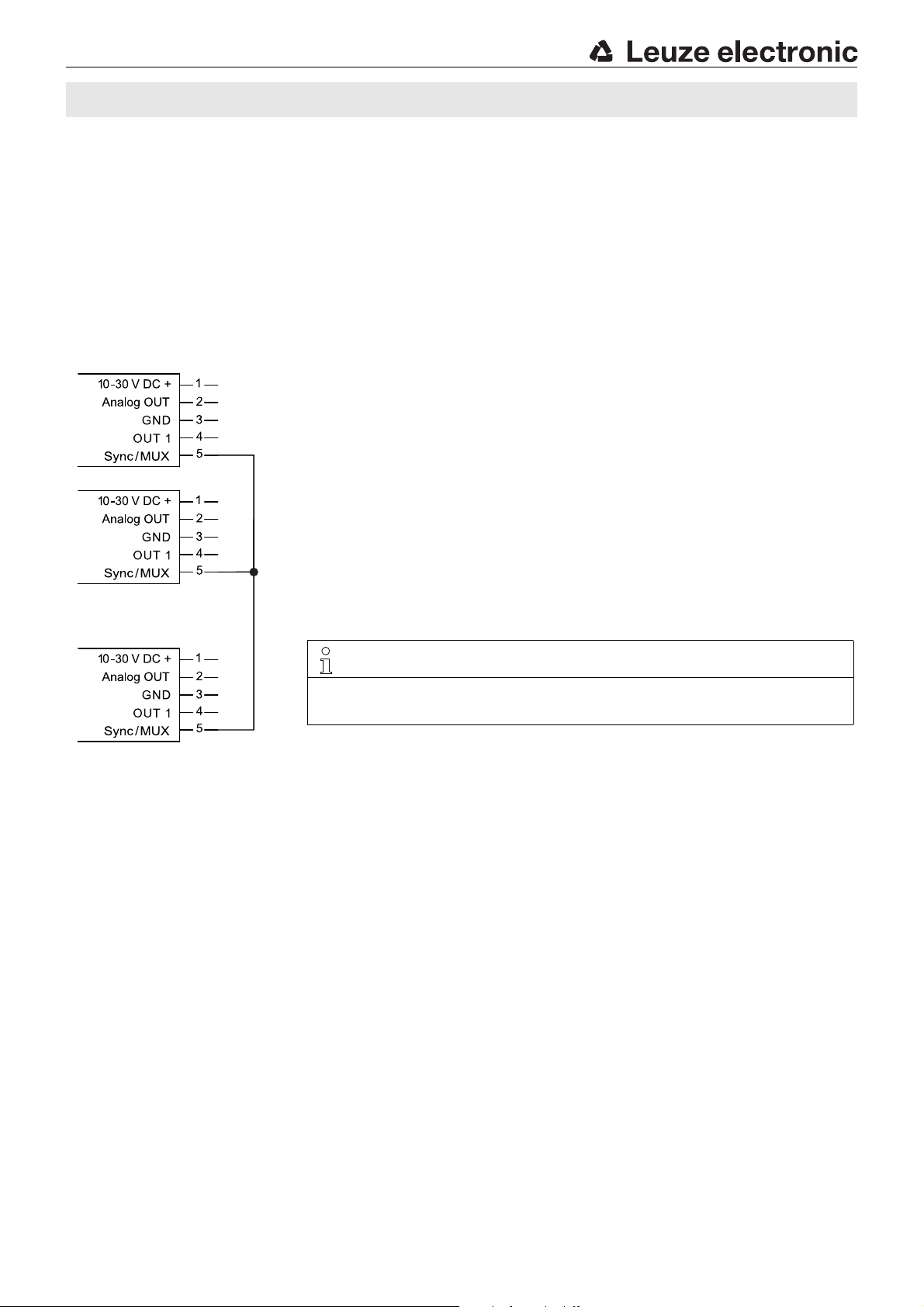
Sensor 2 Sensor 1Sensor n
NOTE
Please make certain that the wiring is performed according to the connection diagram.
Sync/MUX pin 5 on all sensors in the network must be connected to one another. Generation
of the synchronization signal for all sensors in the network occurs automatically.
DMU318…W 90° angled ultrasonic sensors with analog and switching output
Synchronization of multiple DMU318 ultrasonic sensors
If adjacent ultrasonic sensors receive the signals of other sensors, so-called crosstalk occurs, which leads to faulty measurement results.
Through temporal synchronization of the adjacent sensors, this can be avoided. Via the Sync/MUX input, the DMU318 ultrasonic
sensors can be synchronized in 2 different ways:
Synchronous operation
In this operating mode the mutual interference of adjacent sensors can be avoided. For this purpose, up to 6 sensors of the same type
are wired together in a network according to the following diagram.
The devices work in synchronous operation with a simultaneous transmission pulse. The response time of the individual sensors in
the network corresponds approximately to that of a single sensor. However, an additional delay time of approx. 20 ms occurs in
comparison to the specified response time in standard operation.
Synchronous operation wiring schematic
Leuze electronic GmbH + Co. KG In der Braike 1 D-73277 Owen DMU318-400.W…-M12 - 01
DMU318-1600.W…-M12 - 01
Page 10
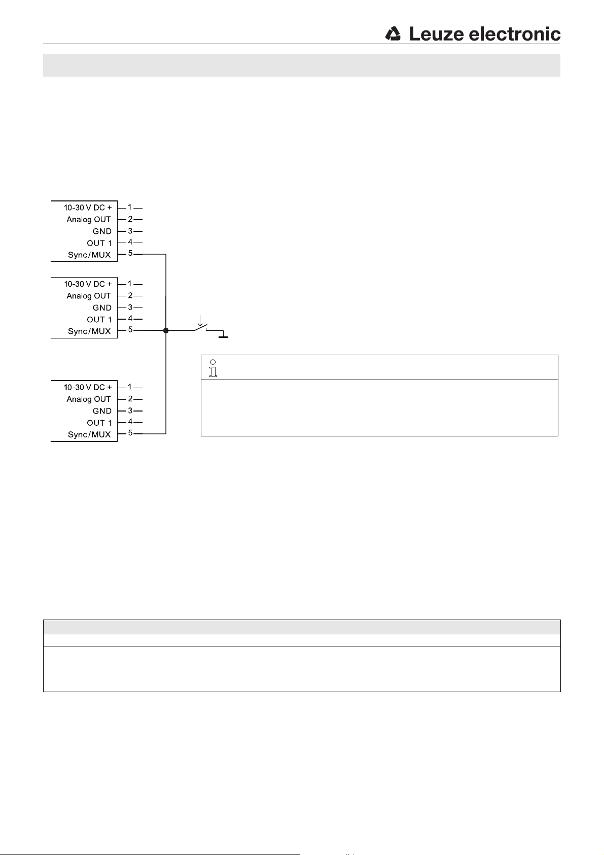
Sensor 2 Sensor 1Sensor n
GND
NOTE
Please make certain that the wiring is performed according to the connection diagram.
Sync/MUX pin 5 on all sensors in the network must be connected to one another.
To activate multiplex operation, the Sync/MUX cable must be connected to GND for 5 s
when applying the operating voltage.
Generation of the multiplex signal for all sensors in the network occurs automatically.
Activating multiplex operation:
to GND for 5s during power-on.
DMU318…W
Multiplex operation
In this operating mode the mutual interference of adjacent sensors can be reliably avoided. For this purpose, up to 4 sensors of the same
type are wired together in a network according to the following diagram.
The devices operate in multiplex operation with a cyclically time-delayed transmission pulse and are switched to a passive state
outside of the active phase, whereby the states of the outputs are frozen until the next active phase. The response time of the individual
sensor in the network is therefore extended with respect to the response time of a single sensor as follows:
Response time in the network = (Response time of sensor * n) + 25ms (n = number of sensors in the network)
Multiplex operation wiring schematic
Resetting to factory settings
The sensor can be reset to the factory setting (1 switching point at 400 mm or 1600 mm, rising characteristic curve with spread over the
entire scanning range).
Resetting to factory settings
1. When switching on the supply voltage (during power-on), press the teach button for >5s.
2. Release the button. The green, yellow and blue LEDs flash alternately and very quickly for a brief time.
The sensor was reset to the factory setting:
switching output: 1 switching point at 400mm or 1600 mm (1-point teach, static),
analog output: 4 … 20mA or 0 … 10 V corresponds to an object distance of 50 … 400 mm or 150 … 1600 mm, respectively.
DMU318-400.W…-M12 - 01 2017/02
DMU318-1600.W…-M12 - 01
 Loading...