

Page 1
AMS 358i
Optical Laser Measurement System
EtherNet/IP
en 03-2014/12 50113351
We reserve the right to
make technical changes
TECHNICAL DESCRIPTION
Page 2

© 2014
Leuze electronic GmbH + Co. KG
In der Braike 1
D-73277 Owen - Teck / Germany
Phone: +49 7021 573-0
Fax: +49 7021 573-199
http://www.leuze.com
Leuze electronic AMS 358i
Page 3
AMS 358i
Navigate
upward/laterally
Navigate
downward/laterally
ESCAPE
leave
ENTER
confirm
Device buttons:
Delete character
Enter digit
Save input
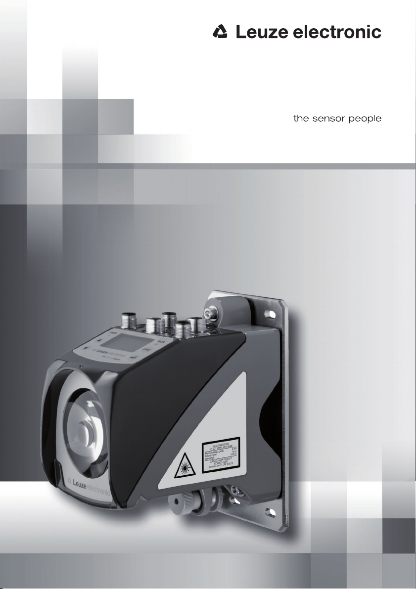
The main menus
ESC
Input of values
AMS 358i 120
Leuze electronic
GmbH & Co. KG
SW: V 1.3.0 HW:1
SN: -----------------------
Network information
Address: ---.---.---.--Net mask: ---.---.---.--Gateway: ---.---.---.--MAC ID: --.--.--.--.--.--
IO1 LSR PLB ENIP
IO2 TMP ATT
ERR
+ 87.000m
Parameter
Parameter handling
EtherNet/IP
Position value
I/O
Other
Device information - main menu
This menu item contains detailed information on
• device model,
• manufacturer,
• software and hardware version,
• serial number.
No entries can be made via the display.
Network information - main menu
Under this menu item, you will find detailed
information on the network addresses.
No entries can be made via the display.
Status- and measurement data - main
menu
• Display of status-, warning-, and error messages.
• Status overview of the switching inputs/outputs.
• Bar graph for the reception level.
• Activated interface.
• Measurement value.
No entries can be made via the display.
See "Indicators in the display" on page 41.
Parameter - main menu
• Configuration of the AMS.
See "Parameter menu" on page 47.
100
<-|0123456789 save
Standard ----- Unit
63 | |
Language selection
o Deutsch
English
o Español
o Français
o Italiano
Service
Status messages
Diagnostics
Expanded diagnostics
Language selection - main menu
• Selection of the display language.
See "Language selection menu" on page 50.
Service - main menu
• Display of status messages.
• Display of diagnostic data.
No entries can be made via the display.
See "Service menu" on page 51.
Page 4

Table of contents
1 General information . . . . . . . . . . . . . . . . . . . . . . . . . . . . . . . . . . . . 5
1.1 Explanation of symbols . . . . . . . . . . . . . . . . . . . . . . . . . . . . . . . . . . . . . . . . . . . . . . . . . . . 5
1.2 Declaration of conformity . . . . . . . . . . . . . . . . . . . . . . . . . . . . . . . . . . . . . . . . . . . . . . . . . 5
1.3 Description of functions AMS 358i . . . . . . . . . . . . . . . . . . . . . . . . . . . . . . . . . . . . . . . . . . 6
2 Safety . . . . . . . . . . . . . . . . . . . . . . . . . . . . . . . . . . . . . . . . . . . . . . . 7
2.1 Intended use . . . . . . . . . . . . . . . . . . . . . . . . . . . . . . . . . . . . . . . . . . . . . . . . . . . . . . . . . . . 7
2.2 Foreseeable misuse. . . . . . . . . . . . . . . . . . . . . . . . . . . . . . . . . . . . . . . . . . . . . . . . . . . . . . 8
2.3 Competent persons . . . . . . . . . . . . . . . . . . . . . . . . . . . . . . . . . . . . . . . . . . . . . . . . . . . . . . 8
2.4 Disclaimer. . . . . . . . . . . . . . . . . . . . . . . . . . . . . . . . . . . . . . . . . . . . . . . . . . . . . . . . . . . . . . 9
2.5 Laser safety notices. . . . . . . . . . . . . . . . . . . . . . . . . . . . . . . . . . . . . . . . . . . . . . . . . . . . . . 9
3 Fast commissioning / operating principle . . . . . . . . . . . . . . . . . . . 12
3.1 Mounting the AMS 358i . . . . . . . . . . . . . . . . . . . . . . . . . . . . . . . . . . . . . . . . . . . . . . . . . . 12
3.1.1 Mounting the device . . . . . . . . . . . . . . . . . . . . . . . . . . . . . . . . . . . . . . . . . . . . . . . . . . . . . 12
3.1.2 Mounting the reflector. . . . . . . . . . . . . . . . . . . . . . . . . . . . . . . . . . . . . . . . . . . . . . . . . . . . 12
3.2 Connecting the voltage supply . . . . . . . . . . . . . . . . . . . . . . . . . . . . . . . . . . . . . . . . . . . . 13
3.2.1 Connecting the EtherNet/IP network . . . . . . . . . . . . . . . . . . . . . . . . . . . . . . . . . . . . . . . . 13
3.3 Display . . . . . . . . . . . . . . . . . . . . . . . . . . . . . . . . . . . . . . . . . . . . . . . . . . . . . . . . . . . . . . . 13
3.4 AMS 358i on EtherNet/IP. . . . . . . . . . . . . . . . . . . . . . . . . . . . . . . . . . . . . . . . . . . . . . . . . 13
4 Specifications . . . . . . . . . . . . . . . . . . . . . . . . . . . . . . . . . . . . . . . . 17
4.1 Specifications of the laser measurement system . . . . . . . . . . . . . . . . . . . . . . . . . . . . . 17
4.1.1 General specifications AMS 358i . . . . . . . . . . . . . . . . . . . . . . . . . . . . . . . . . . . . . . . . . . . 17
4.1.2 Dimensioned drawing AMS 358i . . . . . . . . . . . . . . . . . . . . . . . . . . . . . . . . . . . . . . . . . . . 19
4.1.3 Type overview AMS 358i . . . . . . . . . . . . . . . . . . . . . . . . . . . . . . . . . . . . . . . . . . . . . . . . . 20
5 Installation and mounting . . . . . . . . . . . . . . . . . . . . . . . . . . . . . . . 21
5.1 Storage, transportation . . . . . . . . . . . . . . . . . . . . . . . . . . . . . . . . . . . . . . . . . . . . . . . . . . 21
5.2 Mounting the AMS 358i . . . . . . . . . . . . . . . . . . . . . . . . . . . . . . . . . . . . . . . . . . . . . . . . . . 22
5.2.1 Optional mounting bracket . . . . . . . . . . . . . . . . . . . . . . . . . . . . . . . . . . . . . . . . . . . . . . . . 24
5.2.2 Parallel mounting of the AMS 358i . . . . . . . . . . . . . . . . . . . . . . . . . . . . . . . . . . . . . . . . . . 25
5.2.3 Parallel mounting of AMS 358i and DDLS optical data transmission. . . . . . . . . . . . . . . . 26
5.3 Mounting the AMS 358i with laser beam deflector unit . . . . . . . . . . . . . . . . . . . . . . . . . 27
5.3.1 Mounting the laser beam deflector unit With integrated mounting bracket . . . . . . . . . . . 27
5.3.2 Dimensioned drawing of US AMS 01 deflector unit . . . . . . . . . . . . . . . . . . . . . . . . . . . . . 28
AMS 358i 1
Page 5

Table of contents
5.3.3 Mounting the US 1 OMS deflector unit without mounting bracket . . . . . . . . . . . . . . . . . . 29
6 Reflectors . . . . . . . . . . . . . . . . . . . . . . . . . . . . . . . . . . . . . . . . . . . 30
6.1 General information . . . . . . . . . . . . . . . . . . . . . . . . . . . . . . . . . . . . . . . . . . . . . . . . . . . . .30
6.2 Description of the reflective tape. . . . . . . . . . . . . . . . . . . . . . . . . . . . . . . . . . . . . . . . . . . 30
6.2.1 Specifications of the self-adhesive foil . . . . . . . . . . . . . . . . . . . . . . . . . . . . . . . . . . . . . . . 31
6.2.2 Specifications of the reflective tape on a metal plate . . . . . . . . . . . . . . . . . . . . . . . . . . . .31
6.2.3 Dimensioned drawing of reflective tape on a metal plate . . . . . . . . . . . . . . . . . . . . . . . . . 32
6.2.4 Specifications of heated reflectors . . . . . . . . . . . . . . . . . . . . . . . . . . . . . . . . . . . . . . . . . . 33
6.2.5 Dimensioned drawing of heated reflectors . . . . . . . . . . . . . . . . . . . . . . . . . . . . . . . . . . . . 34
6.3 Selecting reflector sizes . . . . . . . . . . . . . . . . . . . . . . . . . . . . . . . . . . . . . . . . . . . . . . . . . . 35
6.4 Mounting the reflector . . . . . . . . . . . . . . . . . . . . . . . . . . . . . . . . . . . . . . . . . . . . . . . . . . . 36
6.4.1 General information . . . . . . . . . . . . . . . . . . . . . . . . . . . . . . . . . . . . . . . . . . . . . . . . . . . . . . 36
6.4.2 Mounting the reflector . . . . . . . . . . . . . . . . . . . . . . . . . . . . . . . . . . . . . . . . . . . . . . . . . . . .36
6.4.3 Table of reflector pitches . . . . . . . . . . . . . . . . . . . . . . . . . . . . . . . . . . . . . . . . . . . . . . . . . .39
7 Electrical connection . . . . . . . . . . . . . . . . . . . . . . . . . . . . . . . . . . 40
7.1 Safety notices for the electrical connection . . . . . . . . . . . . . . . . . . . . . . . . . . . . . . . . . . 40
7.2 PWR – voltage supply / switching input/output . . . . . . . . . . . . . . . . . . . . . . . . . . . . . . . 41
7.3 EtherNet/IP BUS IN. . . . . . . . . . . . . . . . . . . . . . . . . . . . . . . . . . . . . . . . . . . . . . . . . . . . . .41
7.4 EtherNet/IP BUS OUT. . . . . . . . . . . . . . . . . . . . . . . . . . . . . . . . . . . . . . . . . . . . . . . . . . . . 42
7.5 Service. . . . . . . . . . . . . . . . . . . . . . . . . . . . . . . . . . . . . . . . . . . . . . . . . . . . . . . . . . . . . . . .42
8 Display and control panel AMS 358i . . . . . . . . . . . . . . . . . . . . . . . 43
8.1 Structure of the control panel . . . . . . . . . . . . . . . . . . . . . . . . . . . . . . . . . . . . . . . . . . . . . 43
8.2 Status display and operation . . . . . . . . . . . . . . . . . . . . . . . . . . . . . . . . . . . . . . . . . . . . . . 43
8.2.1 Indicators in the display . . . . . . . . . . . . . . . . . . . . . . . . . . . . . . . . . . . . . . . . . . . . . . . . . . . 43
8.2.2 LED status displays . . . . . . . . . . . . . . . . . . . . . . . . . . . . . . . . . . . . . . . . . . . . . . . . . . . . . . 45
8.2.3 Control buttons . . . . . . . . . . . . . . . . . . . . . . . . . . . . . . . . . . . . . . . . . . . . . . . . . . . . . . . . . 47
8.3 Menu description . . . . . . . . . . . . . . . . . . . . . . . . . . . . . . . . . . . . . . . . . . . . . . . . . . . . . . .48
8.3.1 The main menus . . . . . . . . . . . . . . . . . . . . . . . . . . . . . . . . . . . . . . . . . . . . . . . . . . . . . . . . 48
8.3.2 Parameter menu . . . . . . . . . . . . . . . . . . . . . . . . . . . . . . . . . . . . . . . . . . . . . . . . . . . . . . . . 49
8.3.3 Language selection menu . . . . . . . . . . . . . . . . . . . . . . . . . . . . . . . . . . . . . . . . . . . . . . . . . 52
8.3.4 Service menu . . . . . . . . . . . . . . . . . . . . . . . . . . . . . . . . . . . . . . . . . . . . . . . . . . . . . . . . . . . 53
8.4 Operation. . . . . . . . . . . . . . . . . . . . . . . . . . . . . . . . . . . . . . . . . . . . . . . . . . . . . . . . . . . . . . 53
2 AMS 358i
Page 6

Table of contents
9 EtherNet/IP interface . . . . . . . . . . . . . . . . . . . . . . . . . . . . . . . . . . 56
9.1 EtherNet/IP – general info . . . . . . . . . . . . . . . . . . . . . . . . . . . . . . . . . . . . . . . . . . . . . . . . 56
9.2 Topology . . . . . . . . . . . . . . . . . . . . . . . . . . . . . . . . . . . . . . . . . . . . . . . . . . . . . . . . . . . . . 58
9.3 Addressing . . . . . . . . . . . . . . . . . . . . . . . . . . . . . . . . . . . . . . . . . . . . . . . . . . . . . . . . . . . . 58
9.3.1 Entering the network addresses via the display . . . . . . . . . . . . . . . . . . . . . . . . . . . . . . . . 58
9.4 EtherNet/IP device class . . . . . . . . . . . . . . . . . . . . . . . . . . . . . . . . . . . . . . . . . . . . . . . . . 60
9.4.1 Communication / EDS file. . . . . . . . . . . . . . . . . . . . . . . . . . . . . . . . . . . . . . . . . . . . . . . . . 60
9.5 EtherNet/IP - Electrical connection. . . . . . . . . . . . . . . . . . . . . . . . . . . . . . . . . . . . . . . . . 61
9.6 EDS file - general info . . . . . . . . . . . . . . . . . . . . . . . . . . . . . . . . . . . . . . . . . . . . . . . . . . . 62
9.7 Configuration steps for a Rockwell control without EDS support. . . . . . . . . . . . . . . . . 63
9.7.1 Integrating the hardware into the PLC using the generic Ethernet module . . . . . . . . . . . 63
9.8 Configuration steps for a Rockwell control with EDS support . . . . . . . . . . . . . . . . . . . 64
9.8.1 Integrating the hardware into the PLC and installing the EDS file . . . . . . . . . . . . . . . . . . 64
9.9 Configuration examples. . . . . . . . . . . . . . . . . . . . . . . . . . . . . . . . . . . . . . . . . . . . . . . . . . 66
9.9.1 Example 1 - RSLogix 5000 up to software version V19.xx . . . . . . . . . . . . . . . . . . . . . . . 66
9.9.2 Example 2 - RSLogix 5000 up to software version V19.xx . . . . . . . . . . . . . . . . . . . . . . . 67
9.9.3 Example 3 - RSLogix 5000 for software versions V20.00 and higher . . . . . . . . . . . . . . . 68
9.10 EDS file - detailed description. . . . . . . . . . . . . . . . . . . . . . . . . . . . . . . . . . . . . . . . . . . . . 69
9.10.1 Class 4 Assembly . . . . . . . . . . . . . . . . . . . . . . . . . . . . . . . . . . . . . . . . . . . . . . . . . . . . . . . 69
9.10.2 Class 1 Identity object . . . . . . . . . . . . . . . . . . . . . . . . . . . . . . . . . . . . . . . . . . . . . . . . . . . 74
9.10.3 Class 35 Position sensor object . . . . . . . . . . . . . . . . . . . . . . . . . . . . . . . . . . . . . . . . . . . . 77
9.10.4 Class 100 Display configuration . . . . . . . . . . . . . . . . . . . . . . . . . . . . . . . . . . . . . . . . . . . . 84
9.10.5 Class 103 Switching inputs/outputs. . . . . . . . . . . . . . . . . . . . . . . . . . . . . . . . . . . . . . . . . 85
9.10.6 Class 104 Behavior in the case of error . . . . . . . . . . . . . . . . . . . . . . . . . . . . . . . . . . . . . . 88
9.10.7 Class 105 Velocity monitoring . . . . . . . . . . . . . . . . . . . . . . . . . . . . . . . . . . . . . . . . . . . . . 90
10 Diagnostics and troubleshooting . . . . . . . . . . . . . . . . . . . . . . . . . 94
10.1 Service and diagnostics in the display of the AMS 358i . . . . . . . . . . . . . . . . . . . . . . . . 94
10.1.1 Status messages . . . . . . . . . . . . . . . . . . . . . . . . . . . . . . . . . . . . . . . . . . . . . . . . . . . . . . . 94
10.1.2 Diagnostics . . . . . . . . . . . . . . . . . . . . . . . . . . . . . . . . . . . . . . . . . . . . . . . . . . . . . . . . . . . . 95
10.1.3 Expanded diagnostics . . . . . . . . . . . . . . . . . . . . . . . . . . . . . . . . . . . . . . . . . . . . . . . . . . . 95
10.2 General causes of errors . . . . . . . . . . . . . . . . . . . . . . . . . . . . . . . . . . . . . . . . . . . . . . . . . 95
10.2.1 Power LED . . . . . . . . . . . . . . . . . . . . . . . . . . . . . . . . . . . . . . . . . . . . . . . . . . . . . . . . . . . . 97
10.3 Interface errors. . . . . . . . . . . . . . . . . . . . . . . . . . . . . . . . . . . . . . . . . . . . . . . . . . . . . . . . . 97
10.3.1 Net LED. . . . . . . . . . . . . . . . . . . . . . . . . . . . . . . . . . . . . . . . . . . . . . . . . . . . . . . . . . . . . . . 97
10.4 Status display in the display of the AMS 358i . . . . . . . . . . . . . . . . . . . . . . . . . . . . . . . . 97
AMS 358i 3
Page 7

Table of contents
11 Type overview and accessories . . . . . . . . . . . . . . . . . . . . . . . . . . . 99
11.1 Type key . . . . . . . . . . . . . . . . . . . . . . . . . . . . . . . . . . . . . . . . . . . . . . . . . . . . . . . . . . . . . . 99
11.2 Type overview AMS 358i (EtherNet/IP) . . . . . . . . . . . . . . . . . . . . . . . . . . . . . . . . . . . . . . 99
11.3 Overview of reflector types . . . . . . . . . . . . . . . . . . . . . . . . . . . . . . . . . . . . . . . . . . . . . . 100
11.4 Accessories. . . . . . . . . . . . . . . . . . . . . . . . . . . . . . . . . . . . . . . . . . . . . . . . . . . . . . . . . . . 100
11.4.1 Accessory mounting bracket. . . . . . . . . . . . . . . . . . . . . . . . . . . . . . . . . . . . . . . . . . . . . .100
11.4.2 Accessory deflector unit . . . . . . . . . . . . . . . . . . . . . . . . . . . . . . . . . . . . . . . . . . . . . . . . . 100
11.4.3 Accessory M12 connector. . . . . . . . . . . . . . . . . . . . . . . . . . . . . . . . . . . . . . . . . . . . . . . . 100
11.4.4 Accessory ready-made cables for voltage supply. . . . . . . . . . . . . . . . . . . . . . . . . . . . . . 101
11.4.5 Accessory ready-made cables for EtherNet/IP . . . . . . . . . . . . . . . . . . . . . . . . . . . . . . . . 102
12 Maintenance . . . . . . . . . . . . . . . . . . . . . . . . . . . . . . . . . . . . . . . . 104
12.1 General maintenance information . . . . . . . . . . . . . . . . . . . . . . . . . . . . . . . . . . . . . . . . . 104
12.2 Repairs, servicing . . . . . . . . . . . . . . . . . . . . . . . . . . . . . . . . . . . . . . . . . . . . . . . . . . . . . . 104
12.3 Disassembling, packing, disposing . . . . . . . . . . . . . . . . . . . . . . . . . . . . . . . . . . . . . . . . 104
4 AMS 358i
Page 8
1 General information
U
L
US
C
LISTED
1.1 Explanation of symbols
The symbols used in this operating manual are explained below.
Attention!
This symbol precedes text messages which must strictly be observed. Failure to comply with
this information results in injuries to personnel or damage to the equipment.
Attention Laser!
This symbol warns of possible danger caused by hazardous laser radiation.
Notice!
This symbol indicates text passages containing important information.
1.2 Declaration of conformity
The AMS 358i absolute measuring optical laser measurement system was designed and
manufactured in accordance with applicable European directives and standards.
The AMS series is "UL LISTED" according to American and Canadian safety standards and
fulfills the requirements of Underwriter Laboratories Inc. (UL).
General information
Notice!
The Declaration of Conformity for these devices can be requested from the manufacturer.
The manufacturer of the product, Leuze electronic GmbH + Co. KG in D-73277 Owen/Teck,
possesses a certified quality assurance system in accordance with ISO 9001.
Leuze electronic AMS 358i 5
TNT 35/7-24V
Page 9
General information
1.3 Description of functions AMS 358i
The AMS 358i optical laser measurement system calculates distances to fixed as well as
moving system parts. The distance to be measured is calculated according to the principle
of the propagation time of radiated light. Here, the light emitted by the laser diode is reflected
by a reflector onto the receiving element of the laser measurement system. The AMS 358i
uses the "propagation time" of the light to calculate the distance to the reflector. The high
absolute measurement accuracy of the laser measurement system and the fast integration
time are designed for position control applications.
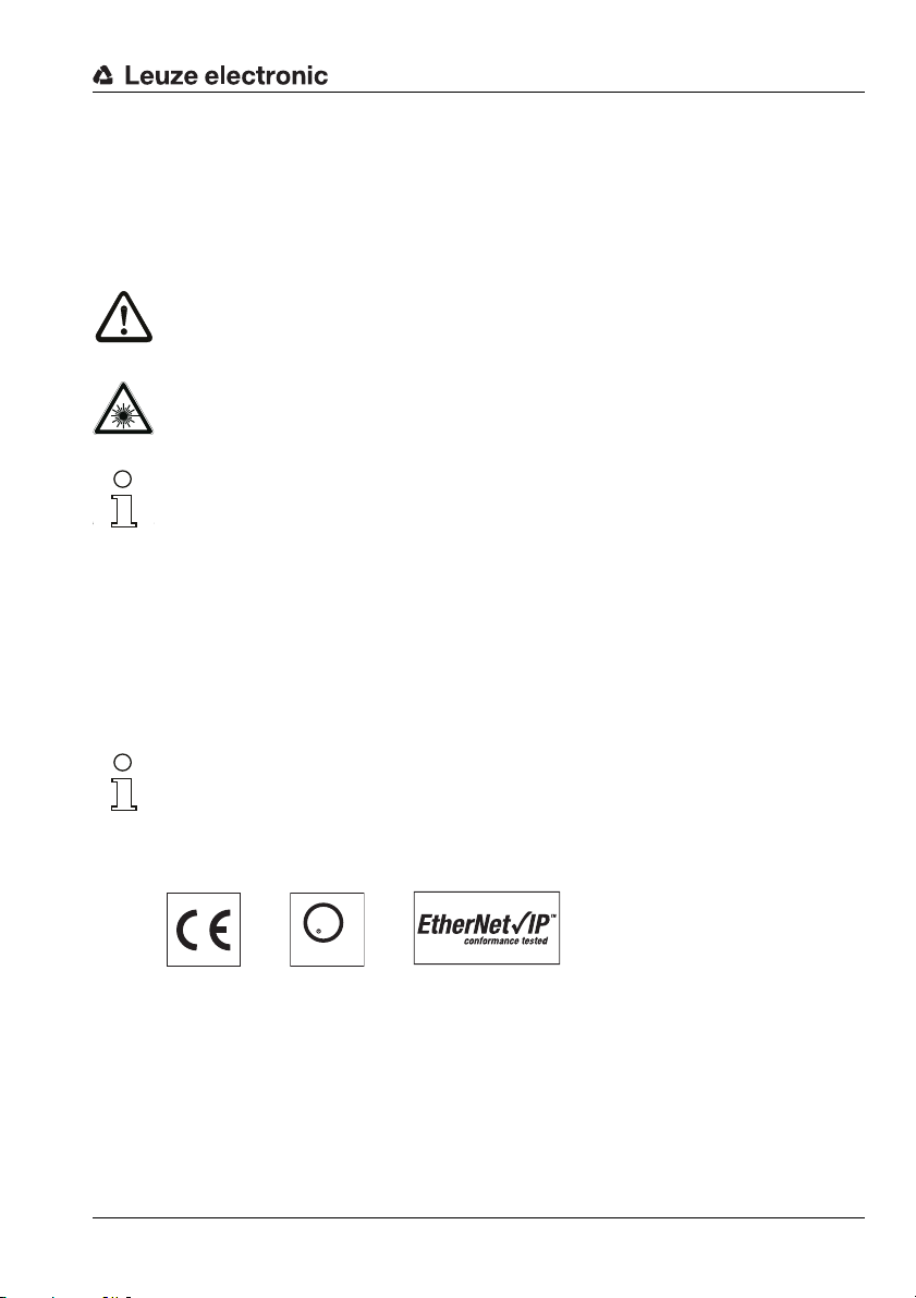
With the AMS 3xxi product series, Leuze electronic makes available a range of internationally relevant interfaces. Note that each interface version listed below corresponds to a
different AMS 3xxi model.
AMS 304i
AMS 348i
AMS 355i
AMS 358i
AMS 335i
AMS 338i
AMS 308i
AMS 384i
AMS 301i
AMS 300i
6 AMS 358i Leuze electronic
Page 10
2 Safety
This sensor was developed, manufactured and tested in line with the applicable safety standards. It corresponds to the state of the art.
2.1 Intended use
The AMS is an absolute measuring optical laser measurement system which allows
distance measurement of up to 300m against a reflector.
Areas of application
The AMS is designed for the following areas of application:
• Positioning of automated, moving plant components
• Travel and lifting axes of high-bay storage devices
• Repositioning units
• Gantry crane bridges and their trolleys
•Lifts
• Electroplating plants
CAUTION
Observe intended use!
Only operate the device in accordance with its intended use. The protection of per-
sonnel and the device cannot be guaranteed if the device is operated in a manner not
complying with its intended use.
Leuze electronic GmbH + Co. KG is not liable for damages caused by improper use.
Read the technical description before commissioning the device. Knowledge of this
technical description is an element of proper use.
Safety
NOTICE
Comply with conditions and regulations!
Observe the locally applicable legal regulations and the rules of the employer's liability
insurance association.
Attention
For UL applications, use is permitted exclusively in Class 2 circuits according to NEC
(National Electric Code).
Leuze electronic AMS 358i 7
TNT 35/7-24V
Page 11

Safety
2.2 Foreseeable misuse
Any use other than that defined under "Intended use" or which goes beyond that use is
considered improper use.
In particular, use of the device is not permitted in the following cases:
• Rooms with explosive atmospheres
• Circuits relevant to safety
• For medicinal purposes
NOTICE
Do not modify or otherwise interfere with the device.
Do not carry out modifications or otherwise interfere with the device.
The device must not be tampered with and must not be changed in any way.
The device must not be opened. There are no user-serviceable parts inside.
Repairs must only be performed by Leuze electronic GmbH + Co. KG.
2.3 Competent persons
Connection, mounting, commissioning and adjustment of the device must only be carried
out by competent persons.
Prerequisites for competent persons:
• They have a suitable technical education.
• They are familiar with the rules and regulations for occupational safety and safety at
work.
• They are familiar with the technical description of the device.
• They have been instructed by the responsible person on the mounting and operation
of the device.
Certified electricians
Electrical work must be carried out by a certified electrician.
Due to their technical training, knowledge and experience as well as their familiarity with
relevant standards and regulations, certified electricians are able to perform work on electrical systems and independently detect possible dangers.
In Germany, certified electricians must fulfill the requirements of accident-prevention regulations BGV A3 (e.g. electrician foreman). In other countries, there are respective regulations that must be observed.
8 AMS 358i Leuze electronic
Page 12
2.4 Disclaimer
Leuze electronic GmbH + Co. KG is not liable in the following cases:
• The device is not being used properly.
• Reasonably foreseeable misuse is not taken into account.
• Mounting and electrical connection are not properly performed.
• Changes (e.g., constructional) are made to the device.
2.5 Laser safety notices
ATTENTION LASER RADIATION – LASER CLASS 2
Never look directly into the beam!
The device satisfies the requirements of IEC 60825-1:2007 (EN 60825-1:2007) safety
regulations for a product in laser class 2 as well as the U.S. 21 CFR 1040.10 regulations
with deviations corresponding to "Laser Notice No. 50" from June 24th, 2007.
Never look directly into the laser beam or in the direction of reflecting laser beams.
If you look into the beam path over a longer time period, there is a risk of injury to the
retina.
Do not point the laser beam of the device at persons!
Interrupt the laser beam using a non-transparent, non-reflective object if the laser
beam is accidentally directed towards a person.
When mounting and aligning the device, avoid reflections of the laser beam off reflec-
tive surfaces!
CAUTION! The use of operating or adjusting devices other than those specified here
or carrying out of differing procedures may lead to dangerous exposure to radiation.
Adhere to the applicable legal and local regulations regarding protection from laser
beams.
The device must not be tampered with and must not be changed in any way.
There are no user-serviceable parts inside the device.
Repairs must only be performed by Leuze electronic GmbH + Co. KG.
Safety
TNT 35/7-24V
Leuze electronic AMS 358i 9
Page 13

Safety
A Laser aperture
B Laser warning sign
C Laser information sign with laser parameters
A B
C
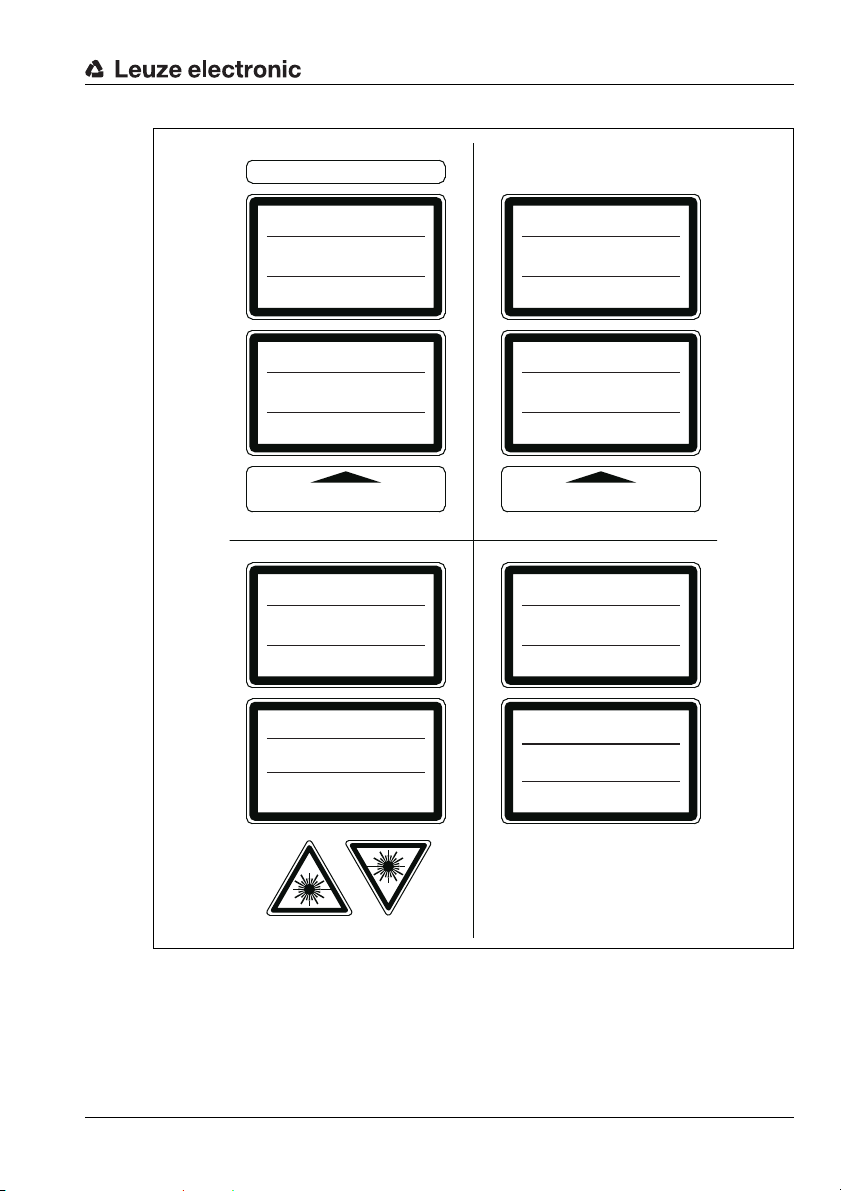
NOTICE
Affix laser information and warning signs!
Laser information and warning signs are attached to the device (see figure 2.1):
In addition, self-adhesive laser warning and information signs (stick-on labels) are supplied
in several languages (see figure 2.2).
Affix the laser information sheet to the device in the language appropriate for the place
of use.
When using the device in the US, use the stick-on label with the "Complies with
21 CFR 1040.10" notice.
Affix the laser information and warning signs near the device if no signs are attached
to the device (e.g., because the device is too small) or if the attached laser information
and warning signs are concealed due to the installation position.
Affix the laser information and warning signs so that they are legible without exposing
the reader to the laser radiation of the device or other optical radiation.
Figure 2.1: Laser apertures, laser warning signs
10 AMS 358i Leuze electronic
Page 14
AVOID EXPOSURE – LASER RADIATION
IS EMITTED FROM THIS APERTURE
EXPOSITION DANGEREUSE – UN RAYONNEMENT
LASER EST ÉMIS PAR CETTE OUVERTURE
LASERSTRAHLUNG
NICHT IN DEN STRAHL BLICKEN
LASER KLASSE 2
DIN EN 60825-1:2008-05
Max. Leistung (peak):
Impulsdauer:
Wellenlänge:
RADIAZIONE LASER
NON FISSARE IL FASCIO
APARRECCHIO LASER DI CLASSE 2
EN 60825-1:2007
Potenza max. (peak):
Durata dell'impulso:
Lunghezza d'onda:
LASER RADIATION
DO NOT STARE INTO BEAM
CLASS 2 LASER PRODUCT
EN 60825-1:2007
Maximum Output (peak):
Pulse duration:
Wavelength:
RAYONNEMENT LASER
NE PAS REGARDER DANS LE FAISCEAU
APPAREIL À LASER DE CLASSE 2
EN 60825-1:2007
Puissance max. (crête):
Durée d`impulsion:
Longueur d`onde:
RADIACIÓN LÁSER
NO MIRAR FIJAMENTE AL HAZ
PRODUCTO LÁSER DE CLASE 2
EN 60825-1:2007
Potencia máx. (peak):
Duración del impulso:
Longitud de onda:
RADIAÇÃO LASER
NÃO OLHAR FIXAMENTE O FEIXE
EQUIPAMENTO LASER CLASSE 2
EN 60825-1:2007
Potência máx. (peak):
Período de pulso:
Comprimento de onda:
LASER RADIATION
DO NOT STARE INTO BEAM
CLASS 2 LASER PRODUCT
IEC 60825-1:2007
Complies with 21 CFR 1040.10
Maximum Output (peak):
Pulse duration:
Wavelength:
䉏⏘戟⺓
▎䦃展⏘㧮
伊䉏⏘ℶ❐
GB7247.1-2012
㦏⮶戢⒉᧤⽿⋋᧥
厘⑁㖐兼㢅梃
㽱栎
4 mW
18 μs
655 nm
4 mW
18 μs
655 nm
4 mW
18 μs
655 nm
4 mW
18
μ
s
655 nm
4 mW
18 μs
655 nm
4 mW
18 μs
655 nm
4 mW
18 μs
655 nm
4 mW
18 μs
655 nm
50125612-01
Safety
Figure 2.2: Laser warning and information signs – supplied stick-on labels
TNT 35/7-24V
Leuze electronic AMS 358i 11
Page 15
Fast commissioning / operating principle
3 Fast commissioning / operating principle
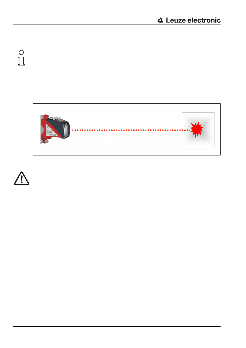
Notice!
Below, you will find a short description for the initial commissioning of the AMS 358i.
Detailed explanations for the listed points can be found throughout the handbook.
3.1 Mounting the AMS 358i
The AMS 358i and the corresponding reflector are mounted on two mutually opposing,
plane-parallel, flat walls.
Figure 3.1: Schematic illustration of mounting
Attention!
For error-free position measurement, there must be an unobstructed line-of-sight between
the AMS 358i and the reflector.
3.1.1 Mounting the device
The laser is mounted on a vertical wall using 4 screws (M5).
Alignment is performed using 2 adjustment screws. Adjust so that the laser light spot is
positioned at the center of the reflector. The alignment is to be secured with the knurled nut
and locked with the M5 nut.
Further information can be found in chapter 5.2 and chapter 5.3.
3.1.2 Mounting the reflector
The reflector is available both as self-adhesive tape and pre-mounted on a metal plate. The
reflector on a metal plate is mounted on a vertical wall with 4 screws (M5). The reflector is
angled using the included shims. Incline the reflector by approx. 1°.
The self-adhesive tape is mounted in the same way, the metal plate must be provided for
it on-site.
Detailed information can be found in chapter 6.4.
12 AMS 358i Leuze electronic
Page 16
Fast commissioning / operating principle
3.2 Connecting the voltage supply
The laser measurement system is connected using M12 connectors. The voltage supply is
connected via the PWR M12 connection.
Detailed information can be found in chapter 7.
3.2.1 Connecting the EtherNet/IP network
The EtherNet/IP is connected via D-coded M12 connectors for BUS IN and BUS OUT.
BUS IN and BUS OUT are coupled by means of an internal switch.
Detailed information can be found in chapter 7.
3.3 Display
Once the laser measurement system is supplied with voltage, the device status as well as
the measured position values can be read on the display. The display automatically switches
to the display of the measurement values.
Use the up/down buttons to the left of the display to read and change a wide range
of data and parameters.
Depending on connected interface, the network address must be configured via the display.
Detailed information can be found in chapter 8.
3.4 AMS 358i on EtherNet/IP
Notice!
Prior to commissioning, the EDS file of the AMS 358i should be installed in the corresponding
control.
Commissioning on the EtherNet/IP is performed according to the following scheme:
1. Activate parameter enabling
2. Address assignment (manual or automatic via DHCP or BootP)
3. Deactivate parameter enabling
4. Configure the participant
5. Transfer the data to the control
6. Configuration of the config assembly, when doing so observe chapter 9.6 without fail
7. Use explicit messaging services
Leuze electronic AMS 358i 13
TNT 35/7-24V
Page 17
Fast commissioning / operating principle
Activating parameter enabling
To be able to perform the subsequent address assignment, parameter enabling must first
be activated.
To do this, select the
Parameter enable menu.
Notice!
The display is inverted while parameter enabling is active.
Manually assigning network addresses of the AMS 358i
In the display under the EtherNet/IP menu item, you will find the input masks for
• IP address,
•Network mask (subnet),
• Gateway address (provided a gateway exists).
Enter the corresponding addresses.
Automatically assigning addresses via DHCP
Under the EtherNet/IP menu item, you will find the input mask for activating or deactivating
the DHCP functionality. DHCP address assignment is set to "ON" by default.
To deactivate DHCP, select OFF.
Provided the DHCP server supplies the corresponding addresses, the address fields for
IP address, network mask and gateway address are preset by the DHCP server.
Automatically assigning addresses via BOOTP
Under the EtherNet/IP menu item, you will find the input mask for activating or deactivating
the BootP functionality. BootP address assignment is set to "OFF" by default.
To activate BootP, select ON.
Provided the BootP server supplies the corresponding addresses, the address fields for
IP address, network mask and gateway address are preset by the BootP server.
ON
menu item in the Parameter -> Parameter handling ->
Notice!
The data can be called up via the display in the main menu under Network information.
Deactivating parameter enabling
To deactivate parameter enabling, select the
Parameter handling -> Parameter enable menu.
OFF
menu item in the Parameter ->
Configuring the participant (up to software version 20.00).
In the RSLogix 5000 configuration tool for EtherNet/IP, a so-called "Generic EtherNet
Module" is created for the AMS 358i under the "Communication" path.
14 AMS 358i Leuze electronic
Page 18
Fast commissioning / operating principle
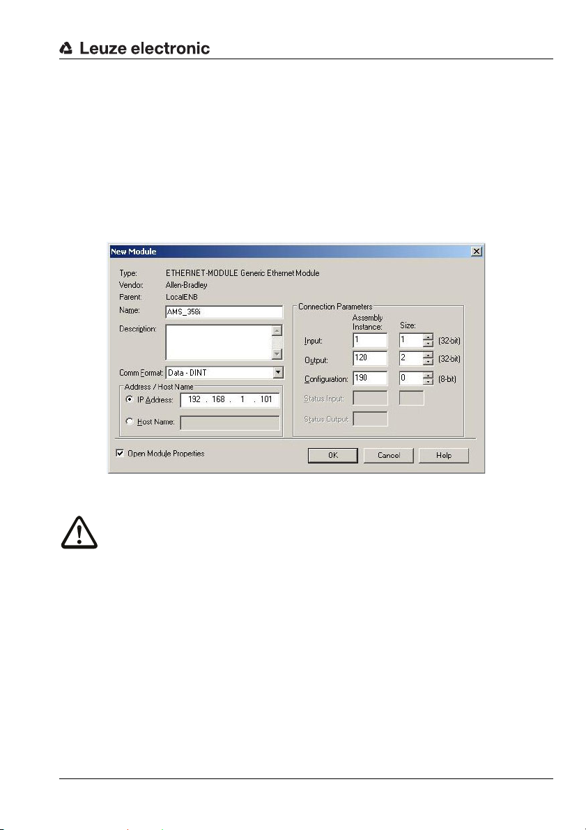
The input mask for the Generic Module describes:
• The name of the participant (can be selected freely; e.g., AMS358i_1).
• The format of the I/O data (Data - DINT = 32bit).
• The IP address of the participant.
• The address and length of the input assembly (instance 1; 1 x 32 bit for the default input
assembly of the measured-value data).
• The address and length of the output assembly (instance 120; 2 x 32 bit for the default
output assembly).
• Optional: The address and length of the configuration assembly (instance 190;
102 x 8bit).
I
Figure 3.2: Input mask generic module
Attention!
If the configuration assembly is addressed with instance 190 and length 102 in the input mask
for the generic module, all AMS 358i parameters with the value 0 are occupied in the first
moment. All default parameters of the AMS manual must be entered in the configuration
assembly. Changing the individual default values is possible at any time.
For the exact description of the assemblies for input/output and configuration, please refer
to chapter 9.10.
The query cycle of the input and output assemblies is subsequently defined in the "Module
Properties - Connection" path in the "Request Packet interval (RPI)" input field.
The participant is thereby defined in offline mode; the data must subsequently be transferred
to the control.
Transfer the data to the control (RSLogix 5000 specific)
Activate online mode.
Leuze electronic AMS 358i 15
TNT 35/7-24V
Page 19
Fast commissioning / operating principle
Select the EtherNet communication port.
Select the processor onto which the project is to be transferred.
Set the control to "PROG".
Start the download.
Set the control to "RUN".
Configure the config assembly
The AMS 358i makes available a configuration assembly that allows the entire parameter
set of the AMS 358i to be saved in the control and, if necessary, to be called up.
The config assembly must include all parameters that affect the AMS 358i. The config
assembly is automatically written to the connected participants in cycles that the control
manufacturer defines.
The config assembly is implemented in class 4, under instance 190. By default, all
parameters are preset to the value 0 (zero).
Attention!
If the config assembly is not adapted, the AMS 358i displays a corresponding behavior acc.
to the parameters preset with 0.
Switch the control to offline mode.
Double-click Controller Tags to edit the configuration assembly.
The configuration assembly can be recognized by the index "C" appended to the device
name.
Parameter entry is performed as described in chapter 9.10.1.5.
Attention!
Activation of the config assembly as described above necessitates value entry in the
corresponding parameter memory locations. When using the configuration assembly, the
default parameters must also be entered in the corresponding memory locations (see also
chapter 9.10.1.5.).
After all of the parameters relevant to the AMS 358i are entered, the control is switched to
"online" and the project is downloaded again.
Using explicit messaging services
Explicit messaging services (e.g., "get attributes …, set attribute …, and others) can be used
to acyclically access all data of the AMS 358i
Attention!
If parameters are changed via explicit messaging services while simultaneously activating a
configuration assembly, the changed parameters must subsequently be entered in the
configuration assembly.
16 AMS 358i Leuze electronic
Page 20

Specifications
4 Specifications
4.1 Specifications of the laser measurement system
4.1.1 General specifications AMS 358i
Measurement data AMS 358i 40 (H) AMS 358i 120 (H) AMS 358i 200 (H) AMS 358i 300 (H)
Measurement range 0.2 … 40m 0.2 … 120m 0.2 … 200m 0.2 … 300m
Accuracy ± 2mm ± 2mm ± 3mm ± 5mm
Consistency
Light spot diameter ≤ 40mm ≤ 100mm ≤ 150mm ≤ 225mm
Measurement value output
Integration time 8ms
Resolution adjustable, see chapter of the individual interfaces
Temperature drift ≤ 0.1 mm/K
Ambient temperature sensitivity 1ppm/K
Air pressure sensitivity 0.3ppm/hPa
Tra ve rs e rate ≤ 10 m/s
Electrical data
Supply voltage Vin
Current consumption without device heating: ≤ 250 mA / 24V DC
Optical data
Transmitter laser diode, red light, wavelength 650 … 690nm
Laser class 2 acc. to EN 60825-1, CDRH
Interfaces
Ethernet/IP 10/100 Mbit/s
Vendor ID 524
Device type 34
Position sensor type 8
Operating and display elements
Keyboard 4 buttons
Display monochromatic graphical display, 128 x 64 pixels
LED 4 LEDs, 2 of which are used to display the Ethernet/IP connection
1)
0.3mm 0.5mm 0.7mm 1.0mm
1.7ms
2)
18 … 30V DC
with device heating: ≤ 500 mA / 24VDC
/ 20C
Dec
/ 22H (encoder)
Dec
/ 8H (absolute encoder)
Dec
H
TNT 35/7-24V
Leuze electronic AMS 358i 17
Page 21
Specifications
Inputs/outputs
Quantity
Input
Output
Mechanical data
Housing cast zinc and aluminum
Optics glass
Weight approx. 2.45kg
Protection class
Environmental conditions
Operating temperature
without device heating
with device heating
Storage temperature -30°C … +70°C
Air humidity max. 90% rel. humidity, non-condensing
Mechanical/electrical loading capacity
Vibrations acc. to EN 60068-2-6
Noise acc. to EN 60060-2-64
Shock acc. to EN 60068-2-27
EMC
1) Statistical error: 1 sigma; minimum switch-on time: 2min.
2) For UL applications: only for use in "Class 2" circuits acc. to NEC.
3) With screwed-on M 12 plugs or mounted caps.
4) With devices with heating, the switch on/off area of the internal heating can be extended to prevent
condensation from forming. A 100% prevention of the formation of condensation cannot be guaranteed due to the limited heating capacity of the AMS 358i.
5) This is a Class A product. In a domestic environment this product may cause radio interference, in
which case the operator may be required to take adequate measures.
acc. to EN 61000-6-2 and EN 61000-6-4
2, programmable
protected against polarity reversal
max. 60mA, short-circuit proof
IP 65 acc. to EN 60529
3)
-5°C … +50 °C
-30°C…+50°C
4)
5)
The AMS 358i is designed in accordance with safety class III for supply with
PELV (protective extra-low voltage).
18 AMS 358i Leuze electronic
Page 22
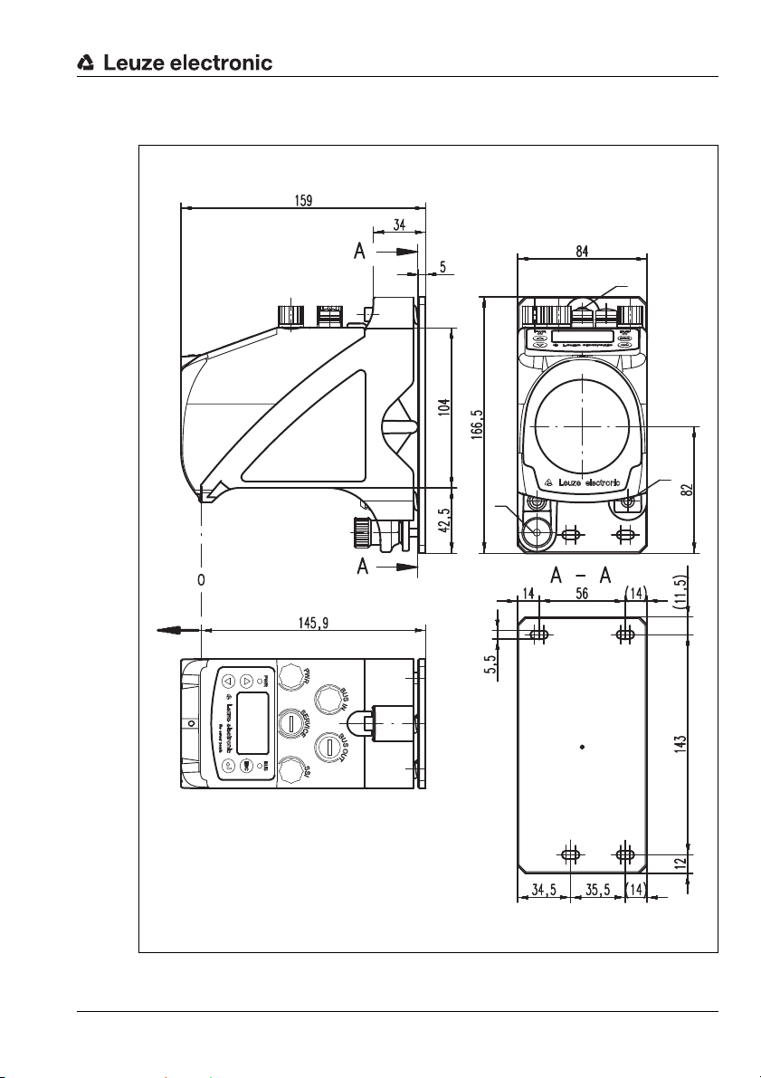
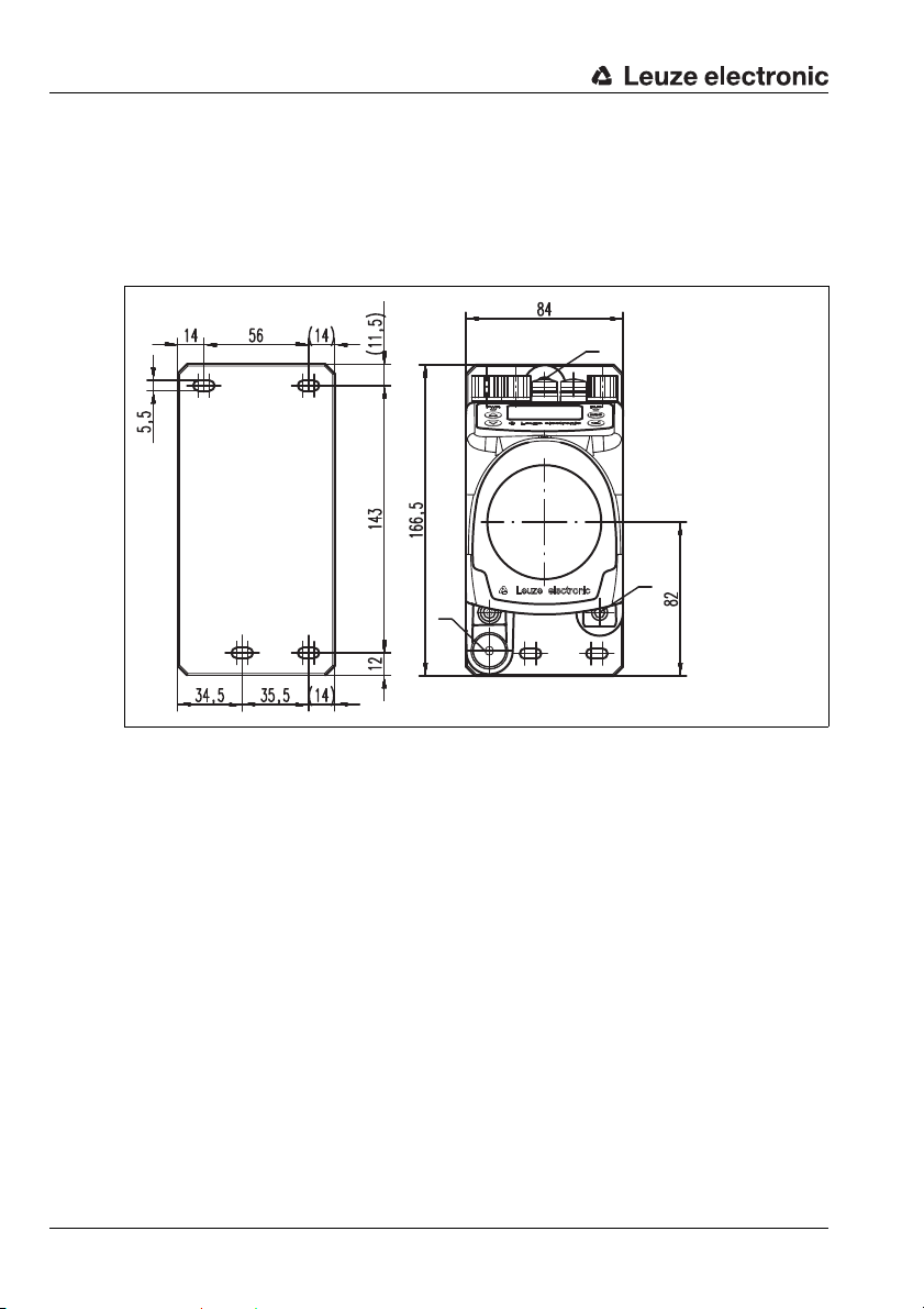
4.1.2 Dimensioned drawing AMS 358i
A M5 screw for alignment
B Knurled nut with WAF4
hexagon socket and M5 nut for securing
C Optical axis
D Zero point of the distance to be measured
A
B
D
A
C
Specifications
Leuze electronic AMS 358i 19
Figure 4.1: Dimensioned drawing AMS 358i
TNT 35/7-24V
Page 23

Specifications
4.1.3 Type overview AMS 358i
AMS 358i (EtherNet/IP)
Type designation Description Part no.
AMS 358i 40 40m operating range, EtherNet/IP interface 50113725
AMS 358i 120 120m operating range, EtherNet/IP interface 50113726
AMS 358i 200 200m operating range, EtherNet/IP interface 50113727
AMS 358i 300 300m operating range, EtherNet/IP interface 50113728
AMS 358i 40 H 40m operating range, EtherNet/IP interface, integrated heating 50113729
AMS 358i 120 H 120m operating range, EtherNet/IP interface, integrated heating 50113730
AMS 358i 200 H 200m operating range, EtherNet/IP interface, integrated heating 50113731
AMS 358i 300 H 300m operating range, EtherNet/IP interface, integrated heating 50113732
Table 4.1: Type overview AMS 358i
20 AMS 358i Leuze electronic
Page 24
5 Installation and mounting
5.1 Storage, transportation
Attention!
When transporting or storing, package the device s o that it i s protected against collision and
humidity. Optimum protection is achieved when using the original packaging. Heed the required environmental conditions specified in the technical data.
Unpacking
Check the packaging for any damage. If damage is found, notify the post office or shipping
agent as well as the supplier.
Check the delivery contents using your order and the delivery papers:
• Delivered quantity
• Device type and model as indicated on the nameplate
• Brief manual
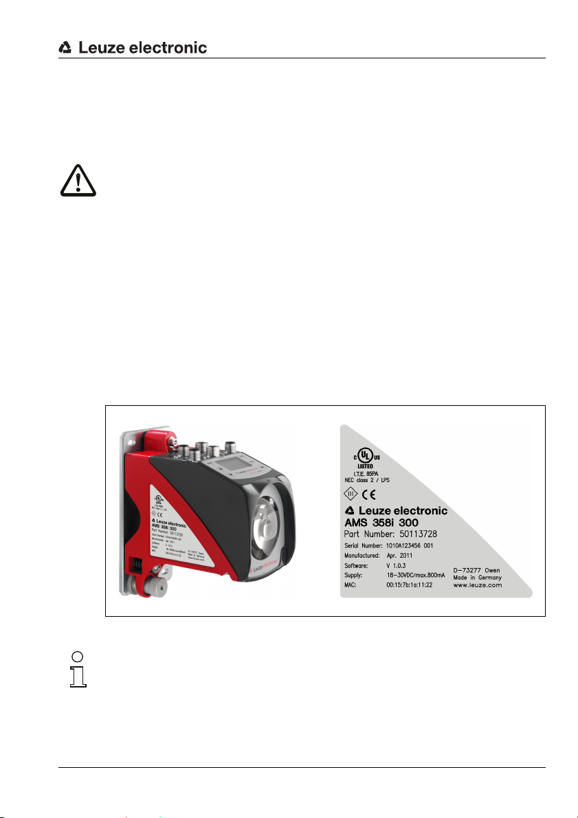
The name plate provides information as to what AMS 358i type your device is. For specific
information, please refer to chapter 11.2.
Name plates
Installation and mounting
Figure 5.1: Device name plate using the AMS 300i as an example
Notice!
Please note that the shown name plate is for illustration purposes only; the contents do not
correspond to the original.
Save the original packaging for later storage or shipping.
Leuze electronic AMS 358i 21
TNT 35/7-24V
Page 25
Installation and mounting
A M5 screw for align-
ment
B Knurled nut and nut
with WAF4 hexagon
socket for securing
C Optical axis
A
B
A
C
If you have any questions concerning your shipment, please contact your supplier or your
local Leuze electronic sales office.
Observe the applicable local regulations when disposing of the packaging materials.
5.2 Mounting the AMS 358i
Figure 5.2: Mounting the device
The AMS 358i and the corresponding reflector are mounted on two mutually opposing,
plane-parallel, flat walls or system parts. For error-free position measurement, there must
be an unobstructed line-of-sight connection between the AMS 358i and the reflector.
Use M5 screws to fasten the laser measurement system. Secure the screws with a toothed
lock washer to protect against loosening caused by vibrations.
22 AMS 358i Leuze electronic
Page 26
Installation and mounting
Aligning the laser light spot in the center of the reflector
The laser light spot has to be aligned so that it always hits the center of the opposing
reflector, both at close range as well as at the maximum measurement distance. To align,
use the two M5 Allen screws ("A" in figure 5.2). When aligning please ensure that the
knurled nut and the lock nut ("B" in figure 5.2) are opened wide.
Attention!
To prevent the laser measurement system from moving out of alignment during continuous
operation, subsequently hand-tighten the knurled nut and counterlock with the nut with
WAF4 hexagon socket ("B" in figure 5.2). Knurled nut and nut must not be tightened until
alignment has been completed.
Attention!
The device must not be opened. Failure to comply will render the guarantee void. Warranted
features cannot be guaranteed after the device has been opened.
Leuze electronic AMS 358i 23
TNT 35/7-24V
Page 27
Installation and mounting
A Laser beam
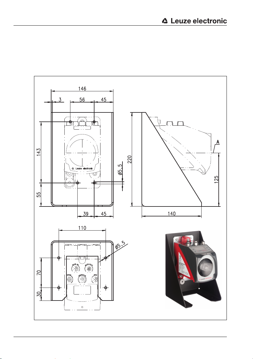
5.2.1 Optional mounting bracket
A mounting bracket for mounting the AMS 358i on a flat, horizontal surface is available as
an optional accessory.
Type designation: MW OMS/AMS 01
Part no.: 50107255
Figure 5.3: Optional mounting bracket
24 AMS 358i Leuze electronic
Page 28
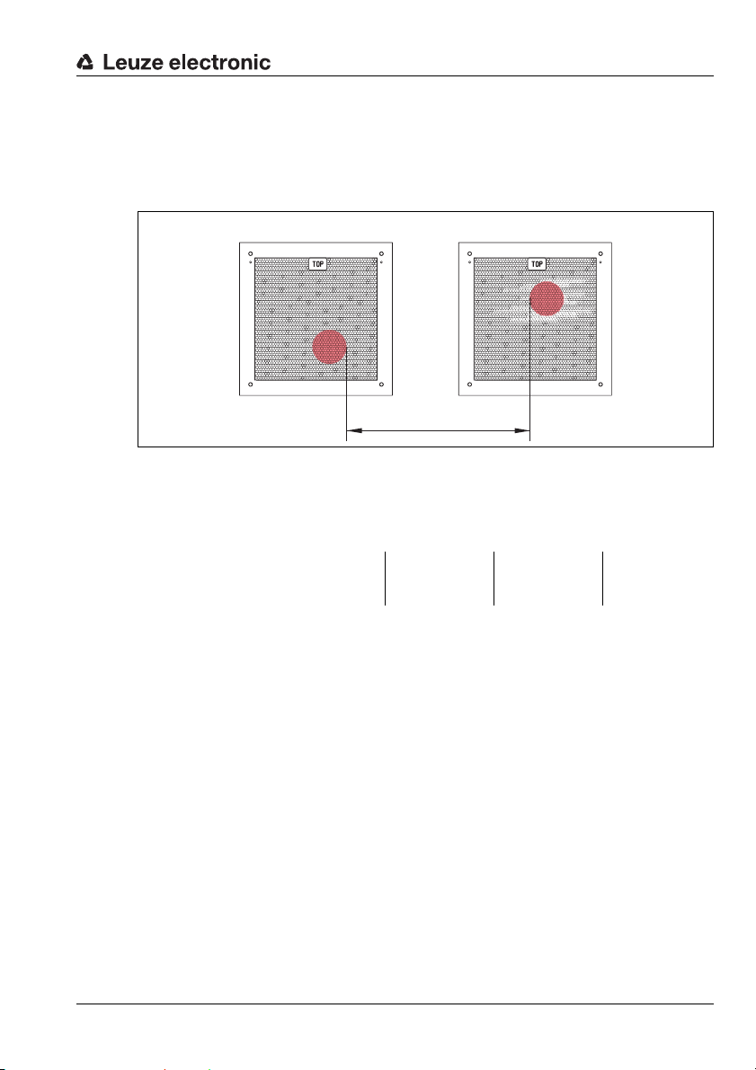
5.2.2 Parallel mounting of the AMS 358i
Reflector 1 Reflector 2
Definition of the term "parallel spacing"
As shown in figure 5.4, dimension X describes the "parallel spacing" of the inner edges of
the two laser light spots on the reflector.
Figure 5.4: Minimum parallel spacing X between adjacent AMS 358i
The diameter of the light spot increases with distance.
AMS 358i 40 (H) AMS 358i 120 (H) AMS 358i 200 (H) AMS 358i 300 (H)
Installation and mounting
X
Max. measurement distance
Light spot diameter ≤ 40mm ≤ 100mm ≤ 150mm ≤ 225 mm
Thus, the center-to-center spacing of the two AMS 358i devices with respect to one another
can be calculated as a function of the maximum measurement distance.
To define the minimum parallel spacing between two AMS 358i, it is necessary to distinguish
between three different arrangements of AMS 358i and reflectors.
40m 120m 200m 300m
The AMS 358i are mounted stationary and in parallel on one plane. Both reflectors move independently of one another at different distances to the AMS 358i.
Minimum parallel spacing X of the two laser light spots:
X = 100mm + (max. measurement distance in mm x 0.01)
The AMS 358i are mounted stationary and in parallel on one plane. Both reflectors move in parallel at the same distance to the AMS 358i.
Measurement distance up to 120 m: minimum parallel spacing X ≥ 600 mm
Measurement distance up to 200 m: minimum parallel spacing X ≥ 750 mm
Measurement distance up to 300 m: minimum parallel spacing X ≥ 750 mm
Leuze electronic AMS 358i 25
TNT 35/7-24V
Page 29

Installation and mounting
The reflectors are mounted stationary and in parallel on one plane.
Both AMS 358i move independently of one another at different or the same distances to the reflectors.
Measurement distance up to 120m: minimum parallel spacing X ≥ 600mm
Measurement distance up to 200m: minimum parallel spacing X ≥ 750mm
Measurement distance up to 300m: minimum parallel spacing X ≥ 750mm
Notice!
Please note that when the AMS 358i are mounted in a mobile manner, travel tolerances could
cause the two laser light spots to move towards each other.
Take the travel tolerances of the vehicle into account when defining the parallel spacing of
adjacent AMS 358i.
5.2.3 Parallel mounting of AMS 358i and DDLS optical data transmission
The optical data transceivers of the DDLS series and the AMS 358i do not interfere with one
another. Depending on the size of the used reflector, the DDLS can be mounted with a
minimum parallel spacing of 100 mm to the AMS 358i. The parallel spacing is independent
of the distance.
26 AMS 358i Leuze electronic
Page 30
Installation and mounting
5.3 Mounting the AMS 358i with laser beam deflector unit
General information
The two available deflector units are used for the 90° deflection of the laser beam,
see "Accessory deflector unit" on page 100.
Attention!
The deflector units are designed for a maximum range of 40m.
Longer distances on request.
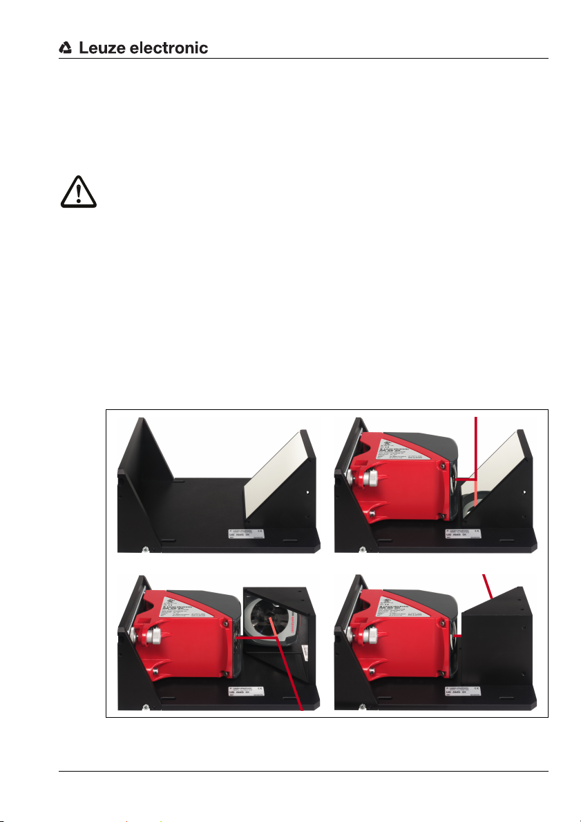
5.3.1 Mounting the laser beam deflector unit With integrated mounting bracket
The AMS 358i is screwed onto the mechanism of the US AMS 01 deflector unit. The mirror
can be mounted for three deflection directions:
1. Upward beam deflection
2. Beam deflection to the left
3. Beam deflection to the right
The deflector unit is mounted on plane-parallel, flat walls or plant components. For error-
free position measurement, there must be an interruption-free line-of-sight between the
AMS 358i… and the deflection mirror as well as between the mirror and the reflector.
Use the M5 screws to mount the deflector unit. Secure the screws with a toothed lock
washer to protect against loosening caused by vibrations.
Figure 5.5: Mounting variants of the US AMS 01 laser beam deflector unit
Leuze electronic AMS 358i 27
TNT 35/7-24V
Page 31

Installation and mounting
A Laser beam
5.3.2 Dimensioned drawing of US AMS 01 deflector unit
Figure 5.6: Dimensioned drawing of US AMS 01 deflector unit
28 AMS 358i Leuze electronic
Page 32

Installation and mounting
A Mirror
Height of the spring in
non-preloaded state
5.3.3 Mounting the US 1 OMS deflector unit without mounting bracket
The US 1 OMS deflector unit and the AMS 358i are mounted separately.
Notice!
When mounting, make certain that the laser light spot of the AMS 358i is aligned in the center
of the deflection mirror.
Figure 5.7: Photo and dimensioned drawing of the US 1 OMS deflector unit
Alignment of the laser light spot on the reflector is performed as described in chapter 5.2.
Leuze electronic AMS 358i 29
TNT 35/7-24V
Page 33

Reflectors
6 Reflectors
6.1 General information
The AMS 358i measures distances against a reflective tape specified by Leuze electronic.
All provided specifications for the AMS 358i, such as the operating range or accuracy, can
only be achieved with the reflective tape specified by Leuze electronic.
The reflective tapes are available as adhesive tapes, affixed to a metal plate and with an
integrated heater especially for use at low temperatures. Reflective tapes with heating have
the designation "Reflective tape …x…-H", where "H" is an abbreviation for the heating
variant.
The reflective tapes/reflectors must be ordered separately. The choice of size is left to the
user. In chapter 6.3, recommendations on reflector size are provided as a function of the
distance that is to be measured. In any case, the user must check to determine whether the
recommendation is suitable for the respective application.
6.2 Description of the reflective tape
The reflective tape consists of a white, microprism-based reflective material. The microprisms are protected with a highly transparent, hard protective layer.
Under certain circumstances, the protective layer may lead to surface reflections. The
surface reflections can be directed past the AMS 358i by positioning the reflective tape at
a slight incline. The inclination of the reflective tape/reflectors is described in chapter 6.4.2.
The required pitch can be found in table 6.1 "Reflector pitch resulting from spacer sleeves"
on page 39.
The reflective tapes are provided with a protective foil that can easily be pulled off. This must
be removed from the reflector before the complete system is put into operation.
30 AMS 358i Leuze electronic
Page 34

6.2.1 Specifications of the self-adhesive foil
Part
Type designation
Part no. 50104361 50104362 50108988
Foil size 200x 200mm 500 x500 mm 914 x914 mm
Recommended application temperature for adhesive tape
Temperature resistance,
affixed
Mounting surface The mounting surface must be clean, dry and free of grease.
Cutting the tape Cut with a sharp tool, always on the side of the prism structure.
Cleaning
Storing the foil Store in a cool and dry place.
Reflective tape
200x200-S
Do not use any agents that act with a grinding effect. A conventional household
detergent can be used as a cleaning agent. Rinse with clear water and dry the
Reflective tape
500x500-S
+5°C … +25°C
-40°C…+80°C
surface.
6.2.2 Specifications of the reflective tape on a metal plate
The reflective tape is affixed to a metal plate. Included with the metal plate are spacers for
positioning at an incline - for avoiding surface reflections - (see chapter 6.4.2 "Mounting the
reflector").
Reflectors
Reflective tape
914x914-S
Part
Type designation
Part no. 50104364 50104365 50104366
Foil size 200x 200mm 500 x500 mm 914 x914 mm
Outer dimensions of the
metal plate
Weight 0.8kg 4kg 25kg
Cleaning
Storing the reflector Store in a cool and dry place.
Leuze electronic AMS 358i 31
Reflective tape
200x200-M
250x 250mm 550 x550 mm 964x964 mm
Do not use any agents that act with a grinding effect. A conventional household
detergent can be used as a cleaning agent. Rinse with clear water and dry the
Reflective tape
500x500-M
surface.
Reflective tape
914x914-M
TNT 35/7-24V
Page 35

Reflectors
Always align the TOP marking
with the AMS connections!
(chapter 6.4.2)
6.2.3 Dimensioned drawing of reflective tape on a metal plate
Figure 6.1: Dimensioned drawing of reflectors
Part Reflective tape (mm) Reflector plate (mm)
xL yL XL YL L
Reflective tape 200x200-M 200 200 250 250 214
Reflective tape 500x500-M 500 500 550 550 514
Reflective tape 914x914-M 914 914 964 964 928
32 AMS 358i Leuze electronic
Page 36

6.2.4 Specifications of heated reflectors
The reflective tape is affixed to a heated, thermally insulated base. The insulation results in
a very high energetic efficiency.
Only the reflective tape is kept at the specified temperature by the integrated heater.
Through the insulation on the back, the generated heat cannot be transferred via the steel
construction. Energy costs are greatly reduced in the case of continuous heating.
Type designation
Part no. 50115020 50115021 50115022
Voltage supply 230VAC
Power 100W 600W 1800 W
Current consumption ~ 0.5A ~ 3A ~ 8A
Length of the supply line 2 m
Size of the reflective tape 200x200 mm 500 x500 mm 914 x914mm
Outer dimensions of the base
material
Weight 0.5kg 2.5 kg 12 kg
Temperature control
Switch-on temperature ~ 5 °C
Switch-off temperature ~ 20°C
Operating temperature -30°C … +70°C
Storage temperature -40°C … +80°C
Air humidity Max. 90%, non-condensing.
Cleaning
Storing the reflector Store in a cool and dry place.
Reflective tape
200x200-H
250x 250mm 550x 550mm 964x 964mm
Controlled heating with the following switch-on and switch-off tempera-
Do not use any agents that act with a grinding effect. A conventional household detergent can be used as a cleaning agent. Rinse with clear water and
Part
Reflective tape
500x500-H
tures, measured at the reflector surface.
dry the surface.
Reflective tape
Reflectors
914x914-H
TNT 35/7-24V
Leuze electronic AMS 358i 33
Page 37

Reflectors
18
6,5
2
L ± 0,5
XL ± 1
TOP
6
2000
115
90
XL ± 1
yL ± 1
L ± 0,5
YL ± 1
Always align the TOP marking
with the AMS connections!
(chapter 6.4.2)
Connection hood
Reflective tape
Si cable
3 x 0.75mm²
6.2.5 Dimensioned drawing of heated reflectors
Figure 6.2: Dimensioned drawing of heated reflectors
Reflective tape 200x200-H 200 200 250 250 214
34 AMS 358i Leuze electronic
Reflective tape 500x500-H 500 500 550 550 514
Reflective tape 914x914-H 914 914 964 964 928
Part Reflective tape (mm) Insulated base plate (mm)
xL yL XL YL L
Page 38

6.3 Selecting reflector sizes
Depending on system design, the reflector can be mounted so that it travels on the vehicle
or it can be mounted at a fixed location.
Attention!
The reflector sizes shown below are a recommendation from Leuze electronic for on-vehicle
mounting of the AMS 358i. For stationary mounting of the AMS 358i, a smaller reflector is
generally sufficient for all measurement distances.
On the basis of the system planning and design, always check whether mechanical travel
tolerances may require the use of a reflector larger than that which is recommended. This
applies, in particular, when the laser measurement system is mounted on a vehicle. During
travel, the laser beam must reach the reflector without interruption. For on-vehicle mounting
of the AMS 358i, the reflector size must accommodate any travel tolerances that may arise
and the associated "wandering" of the light spot on the reflector.
Overview of reflector types
AMS 358i selection
(Operating range in m)
AMS 358i 40 (max. 40 m) 200x200mm Reflective tape 200x200-S
AMS 358i 120 (max. 120m) 500x 500mm Reflective tape 500x500-S
AMS 358i 200 (max. 200m) 749x914mm
AMS 358i 300 (max. 300m) 749x914mm
Recommended reflector sizes
Recommended
reflector size
(H x W)
914x 914mm
914x 914mm
Type designation
…-S = Self-adhesive
…-M = metal plate
…-H = heating
Reflective tape 200x200-M
Reflective tape 200x200-H
Reflective tape 500x500-M
Reflective tape 500x500-H
Reflective tape 749x914-S
Reflective tape 914x914-M
Reflective tape 914x914-S
Reflective tape 914x914-H
Reflective tape 749x914-S
Reflective tape 914x914-M
Reflective tape 914x914-S
Reflective tape 914x914-H
Reflectors
Part no.
50104361
50104364
50115020
50104362
50104365
50115021
50104363
50104366
50108988
50115022
50104363
50104366
50108988
50115022
TNT 35/7-24V
Leuze electronic AMS 358i 35
Page 39

Reflectors
6.4 Mounting the reflector
6.4.1 General information
Self-adhesive reflective tapes
The reflective tapes of the "Reflective tape …x…-S" self-adhesive series must be affixed
to a flat, clean and grease-free surface. We recommend using a separate metal plate, which
is to be provided on-site.
As described in table 6.1, the reflective tape must be angled.
Reflective tapes on metal
The reflective tapes of the "Reflective tape …x…-M" series are provided with corresponding
mounting holes. Spacer sleeves are provided in the packet for achieving the necessary pitch
angle. For further information see table 6.1.
Heated reflectors
The reflective tapes of the "Reflective tape ...x...-H" series are provided with corresponding
mounting holes. Due to the voltage supply affixed on the rear, the reflector cannot be
mounted flat. Included in the package are four distance sleeves in two different lengths. Use
the distance sleeves to achieve a base separation to the wall as well as the necessary pitch
for avoiding surface reflection. For further information see table 6.1.
The reflector is provided with a 2m-long connection cable for supplying with 230V AC.
Connect the cable to the closest power outlet. Observe the current consumptions listed in
the specifications.
Attention!
Connection work must be carried out by a certified electrician.
6.4.2 Mounting the reflector
The combination of laser measurement system and reflective tape/reflector is mounted so
that the laser light spot hits the tape as centered as possible and without interruption.
For this purpose, use the alignment elements provided on the AMS 358i… (see chapter 5.2
"Mounting the AMS 358i"). If necessary, remove the protective foil from the reflector.
Attention!
The "TOP" label mounted on the reflectors should be aligned the same as the connections
of the AMS 358i.
Example:
If the AMS 358i is mounted so that the M12 connections are on the top, the "TOP" label of
the reflector is also on the top. If the AMS 358i is mounted so that the M 12 connections are
on the side, the "TOP" label of the reflector is also on the side.
36 AMS 358i Leuze electronic
Page 40

Reflectors
Pitch approx. 1°
Direct reflection from the
triad structure
Deflected surface reflection due to
the pitch of the reflective tape
Pitch approx. 1°
Spacer sleeves
Notice!
The reflector must be angled. To do this, use the spacer sleeves. Angle the reflectors so that
the surface reflections of the foil seal are deflected to the left, right or upwards, chapter
6.4.3 gives the correct pitch with respect to the reflector size and, thus, the length of the
spacers.
Reflective tapes …-S and …-M
Figure 6.3: Reflector mounting
Figure 6.4: Pitch of the reflector
Leuze electronic AMS 358i 37
TNT 35/7-24V
Page 41

Reflectors
Pitch approx. 1°
Deflected surface reflection due to
the pitch of the reflective tape
Direct reflection from the
triad structure
Pitch approx. 1°
Spacer sleeves
Reflective tapes …-H
Figure 6.5: Mounting of heated reflectors
Figure 6.6: Pitch of the heated reflector
38 AMS 358i Leuze electronic
Page 42

6.4.3 Table of reflector pitches
Reflectors
Reflector type Pitch resulting from spacer sleeves
Reflective tape 200x200-S
Reflective tape 200x200-M
Reflective tape 200x200-H 2 x 15mm 2 x 20mm
Reflective tape 500x500-S
Reflective tape 500x500-M
Reflective tape 500x500-H 2 x 15mm 2 x 25mm
Reflective tape 749x914-S 2x20mm
Reflective tape 914x914-S
Reflective tape 914x914-M
Reflective tape 914x914-H 2 x 15mm 2 x 35mm
1) Spacer sleeves are included in the delivery contents of reflective tape …-M and …-H
Table 6.1: Reflector pitch resulting from spacer sleeves
Notice!
Reliable function of the AMS 358i and, thus, max. operating range and accuracy can only
be achieved with the reflective tape specified by Leuze electronic. No function can be guaranteed if other reflectors are used!
2x5mm
2x10mm
2x20mm
1)
Leuze electronic AMS 358i 39
TNT 35/7-24V
Page 43

Electrical connection
PWR / IOs
M12 connector
(A-coded)
BUS IN
M12 socket
(D-coded)
BUS OUT
M12 socket
(D-coded)
Leuze SERVICE
M12 socket
(A-coded)
7 Electrical connection
The AMS 358i laser measurement systems are connected using variously coded M12
connectors. This ensures unique connection assignments.
Notice!
The corresponding mating connectors and ready-made cables are available as accessories
for all cables. For further information, see chapter 11 "Type overview and accessories".
Figure 7.1: Connections of the AMS 358i
7.1 Safety notices for the electrical connection
Attention!
Before connecting the device, be sure that the supply voltage agrees with the value printed
on the name plate.
The device may only be connected by a qualified electrician.
Ensure that the functional earth (FE) is connected correctly. Unimpaired operation is only
guaranteed when the functional earth is connected properly.
If faults cannot be corrected, the device should be removed from operation and protected
against possible use.
Attention!
For UL applications, use is permitted exclusively in Class 2 circuits according to NEC (National Electric Code).
The laser measurement systems are designed in accordance with safety class III for supply
by PELV (protective extra-low voltage with reliable disconnection).
Notice!
Protection class IP65 is achieved only if the connectors and caps are screwed into place!
40 AMS 358i Leuze electronic
Page 44

Described in detail in the following are the individual connections and pin assignments.
PWR
I/O 2
I/O 1
3
2
1
4
5
GND VIN
FE
M12 plug
(A-coded)
M12 socket
(D-coded)
7.2 PWR – voltage supply / switching input/output
PWR (5-pin plug, A-coded)
Pin Name Remark
1 VIN Positive supply voltage +18 … +30VDC
2 I/O 1 Switching input/output 1
3 GND Negative supply voltage 0 VDC
4 I/O 2 Switching input/output 2
5 FE Functional earth
Thread FE Functional earth (housing)
Table 7.1: Pin assignment PWR
Further information on configuring the input/output can be found in chapter 8 and chapter 9.
7.3 EtherNet/IP BUS IN
BUS IN (4-pin socket, D-coded)
Pin Name Remark
1 TD+ Transmit Data +
2 RD+ Receive Data +
3 TD- Transmit Data -
4 RD- Receive Data -
Thread FE Functional earth (housing)
TD+
BUS IN
RD+
2
1
4
RD-
TD-
3
Electrical connection
TNT 35/7-24V
Leuze electronic AMS 358i 41
Table 7.2: Pin assignments for BUS IN
Page 45

Electrical connection
BUS OUT
TD+
1
2
3
4
RD+
RD-
TD-
M12 socket
(D-coded)
M12 socket
(A-coded)
7.4 EtherNet/IP BUS OUT
Table 7.3: Pin assignment BUS OUT
7.5 Service
SERVICE
RS232-TX
2
NC
1
RS232-RX
GND
3
5
4
NC
BUS OUT (4-pin socket, D-coded)
Pin Name Remark
1 TD+ Transmit Data +
2 RD+ Receive Data +
3 TD- Transmit Data -
4 RD- Receive Data -
Thread FE Functional earth (housing)
Service (5-pin socket, A-coded)
Pin Name Remark
1NC Not used
2 RS232-TX Transmission line RS 232/service data
3 GND Voltage supply 0V DC
4 RS232-RX Receiving line RS 232/service data
5NC Not used
Thread FE Functional earth (housing)
Table 7.4: Service pin assignments
Notice!
The service interface is designed only for use by Leuze electronic!
42 AMS 358i Leuze electronic
Page 46

Display and control panel AMS 358i
Status display
Bar graph
LED
Bus/interface info
LED
Control buttons
Distance measurement value
8 Display and control panel AMS 358i
8.1 Structure of the control panel
Figure 8.1: Structure of the control panel using the AMS 304i PROFIBUS device variant as an example
8.2 Status display and operation
8.2.1 Indicators in the display
Status and warning messages in the display
IO1 Input 1 or output 1 active:
Function depending on configuration.
IO2 Input 2 or output 2 active:
Function depending on configuration.
LSR Warning - laser prefailure message:
TMP Warning - temperature monitoring:
Leuze electronic AMS 358i 43
Laser diode old, device still functional, exchange or have repaired.
Permissible internal device temperature exceeded / not met.
TNT 35/7-24V
Page 47

Display and control panel AMS 358i
ENIP
Activated interface
Maximum position value
IO1 LSR PLB ENIP
IO2 TMP ATT
ERR
+ 87.000m
PLB Plausibility error:
Implausible measurement value. Possible causes: light beam interruption, outside
of measurement range, permissible internal device temperature considerably
exceeded or traverse rate >10m/s.
Depending on the configuration, either zero or the last valid measurement value is
output at the interfaces.
ATT Warning received signal:
Laser outlet window or reflector soiled or fogged by rain, water vapor or fog. Clean
or dry surfaces.
ERR Internal hardware error:
The device must be sent in for inspection.
Bar graph
Indicates the strength of the received laser light.
The center bar represents the ATT warning threshold. The distance value remains
valid and is output at the interfaces.
If no bar graph is available, the PLB status information appears at the same time.
The measurement value has thus been assessed as being implausible. Depending
on the configuration, either zero or the last valid measurement value is output at the
interfaces.
Interface info
An activated EtherNet/IP interface is indicated in the display by means of code "ENIP".
Maximum position value
The measured position value is displayed in the configured unit of measurement.
+87.000m With the metric setting, the measurement value is always displayed in meters
with three decimal places.
+87.0in With the inch setting, the measurement value is always displayed in inches
44 AMS 358i Leuze electronic
with one decimal place.
Page 48

8.2.2 LED status displays
After power ON, a test of the Power LED and Net LED is performed in the following sequence:
1. LEDs off.
2. LEDs are switched to green for approx. 0.25s.
3. LEDs are switched to red for approx. 0.25s.
4. LEDs off.
This is followed by the status display for the power LED (see chapter 9.3) and the Net LED.
PWR LED
Off Device OFF
Flashing green Power LED flashes green
Green continuous light Power LED green
Display and control panel AMS 358i
- No supply voltage
- LED function test for 0.25 s after power up
- No measurement value output
- Voltage connected
- Self test running
- Initialization running
- Parameter download running
- Boot process running
- AMS 358i ok
- Measurement value output
- Self test successfully finished
- Device monitoring active
Red flashing Power LED flashes red
- LED function test for 0.25 s after power up
- Device ok but warning message (ATT, TMP, LSR)
set in display
- Light beam interruption
- Plausibility error (PLB)
Red continuous light Power LED red
- No measurement value output; for details, see
Display
Leuze electronic AMS 358i 45
TNT 35/7-24V
Page 49

Display and control panel AMS 358i
Net
Net
Net
Net
Net
Net
LINK LED for BUS IN LINK LED for BUS OUT
Net LED
Off Net LED off
Flashing green Net LED flashes green
Green continuous light Net LED green
Red flashing Net LED flashes red
Red continuous light Net LED red
Green/red flashing Net LED flashes green/red
LINK LED for BUS IN and BUS OUT
A green/yellow multicolor LED below the BUS IN and BUS OUT connectors indicates the
EtherNet/IP connection status.
- No voltage supply
- No IP address assigned (BootP, DHCP)
- LED function test for 0.25 s after power up
- No EtherNet/IP communication present
- AMS 358i is not assigned to any master
- AMS 358i bus communication ok
- LED function test for 0.25 s after power up
- Time-out in bus communication
- Double IP address
-Self test
Green continuous light LINK LED green
- The link exists, the hardware connection to the next
connected participant is OK.
Flashing yellow LINK LED flashes yellow
- Data is exchanged with the connected participants.
46 AMS 358i Leuze electronic
Page 50

8.2.3 Control buttons
ESC
Delete character
Enter digit
Save
Display and control panel AMS 358i
Up Navigate upward/laterally.
Down Navigate downward/laterally.
ESC
ESC Exit menu item.
ENTER Confirm/enter value, change menu levels.
Navigating within the menus
The menus within a level are selected with the up/down buttons .
The selected menu item is activated with the enter button .
Press the ESC button to move up one menu level.
When one of the buttons is actuated, the display illumination is activated for 10min.
Setting values
If input of a value is possible, the display looks like this:
100
<-|0123456789 save
Default ----------------- unit
126 | |
Use the and buttons to set the desired value. An accidental, incorrect entry can
be corrected by selecting <-| and then pressing .
Then use the buttons to select Save and save the set value by pressing .
Selecting options
If options can be selected, the display looks like this:
TNT 35/7-24V
o OFF
ON
Default ----------------- unit
OFF | |
Select the desired option with the buttons. Activate the option by pressing .
Leuze electronic AMS 358i 47
Page 51

Display and control panel AMS 358i
8.3 Menu description
8.3.1 The main menus
After voltage has been applied to the laser, device information is displayed for several
seconds. The display then shows the measurement window with all status information.
AMS 358i 120
Leuze electronic
SW: V 1.3.0 HW:1
SN: ---------------
GmbH & Co. KG
Device information - main menu
This menu item contains detailed information on
• Device model,
• Manufacturer,
• Software and hardware version,
• Serial number.
No entries can be made via the display.
Network information
Address: ---.---.---.--Net mask: ---.--- .---.--Gateway: ---.---.---.--MAC ID: --.--.--.--.--.--
IO1 LSR PLB ENIP
IO2 TMP ATT
ERR
+ 87.000m
Parameter
Parameter handling
Ethernet/IP
Maximum position value
I/O
Other
Language
selection
o Deutsch
o English
o Español
o Français
Service
Status messages
Diagnostics
Expanded diagnostics
Network information - main menu
• Display of the network settings.
No entries can be made via the display.
Status and measurement data - main menu
• Display of status-, warning-, and error messages
• Status overview of the switching inputs/outputs.
• Bar graph for the reception level.
•Link.
• Measurement value.
No entries can be made via the display.
See "Indicators in the display" on page 43.
Parameter - main menu
• Configuration of the AMS.
See "Parameter menu" on page 49.
Language selection - main menu
• Selection of the display language.
See "Language selection menu" on page 52.
Service - main menu
• Display of status messages.
• Display of diagnostic data.
No entries can be made via the display.
See "Service menu" on page 53.
48 AMS 358i Leuze electronic
Page 52

Notice!
The rear cover of this manual includes a fold-out page with the complete menu structure.
It describes the menu items in brief.
8.3.2 Parameter menu
Parameter handling submenu
The following functions can be called up in the Parameter handling submenu:
• Lock and enable parameter entry
• Set up a password
• Reset the AMS 358i to default settings.
Table 8.1: Parameter handling submenu
Display and control panel AMS 358i
Level 3 Level 4 Level 5 Selection/configuration option
Parameter
enabling
Password Activate
Parameters to
default
password
Password
entry
Description
ON / OFF
The standard setting (OFF) prevents unintended parameter changes.
With parameter enabling activated (ON), the display is inverted. In this
state, it is possible to change parameters manually.
ON / OFF
To enter a password, parameter enabling must be activated.
If a password is assigned, changes to the AMS 358i can only be made
after the password is entered.
The master password 2301 bridges the individually set password.
Configuration option of a four-digit numerical password
By pressing the enter button after selecting
Parameters to default, all parameters are reset to their standard settings without any further security prompts.
In this case, English is selected as the display language.
Standard
OFF
OFF
Additional important information on parameter handling can be found at the end of the
chapter.
EtherNet/IP submenu
Table 8.2: EtherNet/IP submenu
Level 3 Level 4 Level 5 Selection/configuration option
Activation ON / OFF
EtherNet interface
Address Address The IP address can be set to any value in the ---.---.---.--- format.
Gateway The gateway address can be set to any value in the
Description
Normally, the network administrator specifies the IP address that is to be
set here. If DHCP is activated, the setting made here has no effect and
the AMS 358i is set to the values that it obtains from the DHCP server.
---.---.---.--- format.
The AMS 358i communicates with participants in other subnets via the
gateway. Splitting the read application over multiple subnets is rather
uncommon; the setting of the gateway address, thus, usually has no
meaning.
Standard
TNT 35/7-24V
Leuze electronic AMS 358i 49
Page 53

Display and control panel AMS 358i
Table 8.2: EtherNet/IP submenu
Level 3 Level 4 Level 5 Selection/configuration option
Net mask The net mask can be set to any value in the ---.---.---.--- format.
DHCP
activated
BootP
activated
Description
Usually, the AMS 358i is used in a private Class C network and the default
setting can be accepted without change.
Attention: It is possible to enter any values for ---.---.---.--- . Only the
values 255 or 000 are permissible for ---, however. If other values are
set, an error message appears upon restart of the AMS 358i.
ON / OFF
If DHCP is activated, the AMS 358i draws its settings for IP address, gateway and net mask from a DHCP server. The manual settings made above
have no effect, but are retained and are again active if DHCP is deactivated.
ON / OFF
If BootP is activated, the AMS 358i draws its settings for IP address, ga teway and net mask from a BootP server. The manual settings made above
have no effect, but are retained and are again active if BootP is deactivated.
Position value submenu
Table 8.3: Position value submenu
Level 3 Level 4 Level 5 Selection/configuration option
Measurement
unit
Count direction Positive/Negative
Offset Output value=measurement value+offset.
Preset The preset value is accepted by means of teach pulse. The teach pulse
Free resolution
value
Description
Metric/Inch
Specifies the units of the measured distances
Positive: The measurement value begins at 0 and increases with increasing distance.
Negative: The measurement value begins at 0 and decreases with
increasing distance. Negative distance values may need to be compensated with an offset or preset.
The resolution of the offset value is independent of the selected "Resolution position" and is entered in mm or inch/100. The offset value is
effective immediately following entry. If the preset value is activated, this
has priority over the offset. Preset and offset are not offset against each
other.
can be applied to a hardware input of the M12 PWR connector. The hardware input must be appropriately configured. See also configuration of
the I/Os.
The measurement value can be resolved in increments of 1/1000 within
the 5 … 50000 value range. If, e.g., a resolution of 0.875mm per digit
is required, the parameter is set to 875.
Standard
ON
OFF
Standard
Metric
Positive
0mm
0mm
1000
Error delay ON / OFF
Position value in
the case of error
Specifies whether, in the event of an error, the position value immedia tely
outputs the value of the "Position value in the case of error" parameter
or the last valid position value for the configured error delay time.
Last valid value / zero
Specifies which position value is output after the error delay time elapses.
ON/100 ms
Zero
50 AMS 358i Leuze electronic
Page 54

I/O submenu
Table 8.4: I/O submenu
Display and control panel AMS 358i
Level 3 Level 4 Level 5 Selection/configuration option
I/O 1 Port config-
I/O 2 Port config-
Limit values Upper pos.
uration
Switching
input
Switching
output
uration
Switching
input
Switching
output
limit 1
Lower pos.
limit 1
Upper pos.
limit 2
Lower pos.
limit 2
Function No function/preset teach/laser ON/OFF No function
Activation Low active/High active Low active
Function Pos. limit value 1 / Pos. limit value 2 / Velocity / Intensity (ATT) /
Activation Low active/High active Low active
Function No function/preset teach/laser ON/OFF No function
Activation Low active/High active Low active
Function Pos. limit value 1 / Pos. limit value 2 / Velocity / Intensity (ATT) /
Activation Low active/High active Low active
Activation ON / OFF OFF
Limit value
input
Activation ON / OFF OFF
Limit value
input
Activation ON / OFF OFF
Limit value
input
Activation ON / OFF OFF
Limit value
input
Description
Input/Output
Defines whether I/O 1 functions as an output or input.
Temp. (TMP) / Laser (LSR) / Plausibility (PLB) / Hardware (ERR)
The individual functions are "ORed" on the selected switching output.
Input/Output
Defines whether I/O 2 functions as an output or input.
Temp. (TMP) / Laser (LSR) / Plausibility (PLB) / Hardware (ERR)
The individual functions are "ORed" on the selected switching output.
Value input in mm or inch/100 0
Value input in mm or inch/100 0
Value input in mm or inch/100 0
Value input in mm or inch/100 0
Standard
Output
Plausibility (PLB),
hardware (ERR)
Output
Intensity (ATT),
Tem p. ( TM P) ,
Laser (LSR)
TNT 35/7-24V
Leuze electronic AMS 358i 51
Page 55

Display and control panel AMS 358i
Other submenu
Table 8.5: Other submenu
Level 3 Level 4 Level 5 Selection/configuration option
Heating control Standard (10°C … 15°C)/Extended (30° C … 35°)
Display illumination
Display contrast Weak/Medium/Strong
Service RS232 Baud rate 57.6kbit/s / 115.2kbit/s
Format 8,e,1 / 8,n,1
8.3.3 Language selection menu
Language
selection
o Deutsch
English
o Español
o Français
There are 5 display languages available:
•German
• English
•Spanish
•French
• Italian
The AMS 358i is delivered from the factory with the display preset to English.
To change the language, no password needs to be entered nor must password enabling
be activated. The display language is a passive operational control and is, thus, not a function parameter, per se.
Description
Defines a switch-on/switch-off range for the heating control.
The extended switch-on/switch-off range for heating may provide relief
in the event of condensation problems.
There is no guarantee that no condensation will occur on the optics in the
extended switch-on/switch-off range due to the limited heating capacity.
This parameter is available as standard, but functions only for devices
with integrated heating (AMS 358i… H).
10 minutes/ON
Display illumination is switched off after 10 minutes or, if the parameter
is set to "ON", illumination is always on.
The display contrast may change at extreme temperature values. The
contrast can subsequently be adapted using the three levels.
The service interface is only available to Leuze internally.
The service interface is only available to Leuze internally.
Standard
Standard
10min.
Medium
115.2kbit/s
8,n,1
52 AMS 358i Leuze electronic
Page 56

8.3.4 Service menu
Service
Status messages
Diagnostics
Expanded diagnostics
A more detailed description of the individual functions can be found in chapter 10.
8.4 Operation
Described here is an operating process using parameter enabling as an example.
Parameter enabling
During normal operation parameters can only be viewed. If parameters are to be changed,
the ON menu item in the Parameter -> Parameter handling -> Parameter enable
menu must be activated. To do this, proceed as follows:
Parameter
Parameter handling
Ethernet/IP
Maximum position value
I/O
Other
Parameter handling
o Parameter enabling
o Password
Parameters to default
Display and control panel AMS 358i
In the main menu, press the enter button to enter the
Parameter menu.
Use the buttons to select the Parameter
handling menu item.
Press the enter button to enter the Parameter
handling menu.
In the Parameter handling menu, use the
buttons to select the Parameter enabling
menu item.
Press the enter button to enter the Parameter
enabling menu.
Parameter enabling
o OFF
oON
In the Parameter enabling menu, use the
buttons to select the ON menu item.
Leuze electronic AMS 358i 53
TNT 35/7-24V
Page 57

Display and control panel AMS 358i
Parameter enabling
o OFF
ON
Press the enter button to switch on parameter
enabling.
The PWR LED illuminates orange; the display is
inverted. You can now set the individual parameters
on the display.
ESC ESC
Press the ESC button twice to return to the Parameter menu.
Viewing and editing parameters
As long as parameter enabling is activated, the entire AMS 358i display is inverted.
As long as parameter enabling is activated, communication between control and AMS 358i
is interrupted. The continued networking via BUS OUT is retained.
Attention!
The AMS 358i offers a configuration assembly. If this is activated in the control, all parameters are to be entered there.
The configuration assembly is automatically downloaded to the AMS according to the
criteria of the respective control.
This results in parameters that were manually changed via the display/panel being restored
by the control to the state of the configured configuration assembly. The parameters that
were manually changed via the display are, thus, no longer valid.
The address setting performed on the AMS 358i for EtherNet/IP is not affected by the automatic parameter download performed by the control.
Attention!
If the configuration assembly function is not activated, parameters set manually via the display/panel become active the moment parameter enabling is again deactivated on the
AMS 358i.
Notice!
If a password was stored, parameter enabling is not possible until this password is entered,
see "Password for parameter enabling" below.
Password for parameter enabling
Parameter entry on the AMS 358i can be protected with a password. With the AMS 358i,
the password is defined via the EDS file (class 100, instance 1) or via the configuration
assembly. Thus, the password cannot be changed by means of display entry.
To activate parameter enabling via the display (e.g., to enter an IP address), the defined
password must be entered via the display. If parameter enabling has been activated after
successfully entering the password, parameters can temporarily be changed via the display.
After parameter enabling is deactivated, all changes made on the display are overwritten
by the configuration assembly (see above). If a new password has been assigned, this, too,
is overwritten by the password defined in the configuration assembly.
54 AMS 358i Leuze electronic
Page 58

Display and control panel AMS 358i
Notice!
The master password 2301 can enable the AMS 358i at any time.
Leuze electronic AMS 358i 55
TNT 35/7-24V
Page 59

EtherNet/IP interface
9 EtherNet/IP interface
9.1 EtherNet/IP – general info
EtherNet/IP is an industrial communication network based on EtherNet and builds upon the
TCP/IP and UDP/IP protocols.
EtherNet/IP makes use of the (CIP) Common Industrial Protocol as an application layer for
the user. CIP distinguishes between real-time communication by means of "implicit
messages" and custom, acyclic services, which are referred to as "explicit messages".
Explicit messages
Explicit messages are sent on the basis of TCP/IP. The receiver interprets the message as
an instruction, executes it, and generates a corresponding response. Explicit messages are
used, e.g., for device configuration, programming and for diagnostics and for communicating non-time-critical data; they do not have a real-time characteristic.
Explicit messages are always sent using point-to-point communication.
All EDS objects of the AMS 358i described in the following can be called up via explicit
services (e.g., get attribute single, set attribute single, etc.).
Implicit messages
Implicit messages are used to send real-time I/O data. For this purpose, EtherNet/IP does
not use TCP, but rather UDP (User Datagram Protocol) via IP (Internet Protocol). This
protocol is much more compact and supports multicast as well as unicast messages.
Implicit message telegrams are cyclically sent in short intervals with current data and I/O
signals (cycle can be configured via the control). The telegram overhead is minimal here. As
a result, these messages can be processed very quickly and according to priority.
Within the AMS 358i, the input and output assemblies for transferring measurement values
by means of UDP are transferred and are thereby deterministically available in a cycle configured via the control.
For implicit messages, EtherNet/IP uses the producer/consumer communication model for
data exchange. A producer is a device that sends data; a consumer is a device that receives
data. Multiple consumers can thereby simultaneously receive and evaluate a producer
message in the multicast operating mode.
In general, it must be observed that, when using multicast, the messages are sent to all
participants by way of a broadcast. This causes the data traffic on the network to increase
considerably. Should the data only be transmitted between the AMS and the PLC, we
recommend configuring the unicast operating mode on the control for this participant.
56 AMS 358i Leuze electronic
Page 60

EtherNet/IP interface
Thus, EtherNet/IP combines TCP/IP and UDP/IP data telegrams for the transfer of explicit
and implicit messages. As a result, EtherNet/IP can use both real-time I/O data for timecritical control tasks (UDP) as well as information data (TCP) in parallel on a single network.
All data of the AMS 358i is represented via CIP in an object-oriented manner and is accessible to the user through the explicit and implicit messaging services described above.
Serving as the common configuration basis within CIP is the EDS file (Electronic Data
Sheet). The EDS file of the AMS 358i contains predefined input and output assemblies for
UDP-based, real-time transfer as well as all configuration and diagnostic data for the TCP/
IP-based services.
Notice!
The AMS 358i communicates via the Common Industrial Protocol (CIP).
CIP Safety, CIP Sync and CIP Motion are not supported by the AMS 358i.
The EDS file for the AMS 358i can be found on the Leuze website www.leuze.com.
Leuze electronic AMS 358i 57
TNT 35/7-24V
Page 61

EtherNet/IP interface
9.2 Topology
The AMS 358i can be used in all topologies defined by EtherNet/IP. The M12 connections
for BUS IN and BUS OUT are coupled to one another via an integrated switch. The AMS 358i
can thus be used to further branch EtherNet/IP on the basis of standard CIP.
If parameter enabling of the AMS 358i is activated via the display, the AMS 358i is deactivated as a participant. This serves to prevent parameter access conflicts. In this case, it is
possible as before to communicate with the participant connected via BUS OUT.
Notice!
The AMS 358i supports the DLR (Device-Level_Ring) ring structure determined by the
ODVA.
9.3 Addressing
Each participant connected to EtherNet/IP must be assigned its own IP address. Addressing
can be performed manually or automatically via DHCP or BootP.
By default, DHCP is set to "ON", BootP is set to "OFF". Both settings can be changed via
the display.
Note!
Basic operation of the display is described in chapter 8.2.
To set the network addresses manually (not via DHCP), parameter enabling must be
activated. The display is inverted with parameter enabling activated.
Attention!
The laser measurement system is deactivated on the EtherNet/IP when parameter enabling
is activated via the display. The device is reactivated on the EtherNet/IP after parameter
enabling is exited.
9.3.1 Entering the network addresses via the display
To do this proceed as follows:
Activate parameter enabling.
Select the EtherNet/IP submenu.
Select the IP address menu item.
Enter the EtherNet IP address and save your entry with save.
Select the Gateway menu item.
Enter the gateway address and save your entry with save.
Select the Net mask menu item.
Enter the address of the net mask and save your entry with save.
Deactivate parameter enabling.
58 AMS 358i Leuze electronic
Page 62

EtherNet/IP interface
ESC
ESC
ESC
ESC
ESC
For information on manual address assignment for the IP address, the net mask (subnet)
as well as any gateway, refer to the structure shown below.
EtherNet interface
Address
Gateway
Net mask
DHCP activated
Address
---.---.---.---
012345678 save
Standard
---.---.---.---
EtherNet interface
Address
Gateway
Net mask
DHCP activated
EtherNet interface
Address
Gateway
Net mask
DHCP activated
BootP activated
EtherNet interface
Address
Gateway
Net mask
Gateway
---.---.---.---
012345678 save
Standard
---.---.---.---
Net mask
---.---.---.---
012345678 save
Standard
---.---.---.---
Activation
o OFF
o ON
DHCP activated
BootP activated
EtherNet interface
Address
Gateway
Net mask
Activation
o OFF
o ON
DHCP activated
BootP activated
The complete menu structure can be found at the end of the description.
TNT 35/7-24V
Leuze electronic AMS 358i 59
Page 63

EtherNet/IP interface
All addressing, including the MAC ID, can be called up via the Network information main
menu mask.
Network information
Address: ---.---.---.--Net mask: ---.---.---.--Gateway: ---.---.---.--MAC ID: --.--.--.--.--.--
9.4 EtherNet/IP device class
EtherNet/IP defines four different device classes. Serving as the basis for this is the fundamental behavior of the devices, their intended use and the product types assigned to a
device class.
Furthermore, the device class defines the supported EtherNet/IP communication. The
device class indicates whether explicit and implicit messages can be exchanged with the
participant.
The device classes are divided into server, client, adapter and scanner.
The AMS 358i is assigned to the "adapter" device class and can thus receive and send both
implicit and well as explicit messages.
9.4.1 Communication / EDS file
The EDS file is an integral part of the AMS 358i. All AMS 358i data can be called up via the
object-, instance- and attribute addresses described in the following.
The EDS file makes available input and output assemblies for implicit (real-time) communication as well as a configuration assembly for all device parameters.
In addition, all data can be called up via explicit calls.
Notice!
The possibility of integrating the EDS file in the control is not standardized. Clarify with your
control manufacturer as to whether integration in the control is supported.
If necessary, the EDS file can be downloaded from the Leuze website www.leuze.com.
The data is addressed according to the following fundamental scheme:
1. Device address (IP address)
The participant is addressed with its IP address, which is unique in the network.
2. Object class identifier (class)
Used as the basis for addressing the desired object class.
3. Object instance identifier (instance)
Addressing of the object instance within the object class.
60 AMS 358i Leuze electronic
Page 64

4. Attribute identifier (attribute)
M12 socket
(D-coded)
M12 socket
(D-coded)
BUS IN (4-pin socket, D-coded) BUS OUT (4-pin socket, D-coded)
Pin Name Remark Pin Name Remark
1TD+Transmit Data + 1TD+Transmit Data +
2RD+Receive Data + 2RD+Receive Data +
3TD-Transmit Data - 3TD-Transmit Data -
4RD-Receive Data - 4RD-Receive Data -
Thread FE Functional earth (housing) Thread FE Functional earth (housing)
BUS IN
TD+
1
2
3
4
RD+
RD-
TD-
Addressing of the attribute within the object instance.
5. Service code (get, set, reset, start, stop and others...)
The maintenance code ultimately describes the type of access to the data, e.g.,
reading or writing.
9.5 EtherNet/IP - Electrical connection
EtherNet/IP interface
BUS OUT
RD+
2
TD+
1
RD-
TD-
3
4
Figure 9.1: EtherNet/IP - Electrical connection
Notice!
For contacting BUS IN and BUS OUT, we recommend our ready-made EtherNet cable (see
chapter 11.4.5 "Accessory ready-made cables for EtherNet/IP").
TNT 35/7-24V
Leuze electronic AMS 358i 61
Page 65

EtherNet/IP interface
9.6 EDS file - general info
An EDS file (Electronic Data Sheet) is provided for the AMS 358i.
The EDS file is named "AMS358i.eds"; the corresponding icon is named "AMS358i.ico"
Both files are available in the Download area of the Leuze website www.leuze.com.
The EDS file contains all identification and communication parameters of the device, as well
as the available objects.
The AMS 358i is uniquely classified via a class 1 identity object (component of the
AMS358i.eds file) for the EtherNet/IP scanner (master).
The identity object contains, among other things, a manufacturer-specific vendor ID, as well
as an ID that describes the principle function of the participant.
The AMS 358i has the following identity object (class 1):
Vendor ID: 524
Device type: 34
Position sensor type: 8
/ 20C
Dec
H
/ 22H (identifies the AMS 358i as "encoder")
Dec
/ 8H (specifies the AMS 358i as "absolute encoder")
Dec
If accepting the objects without change, all parameters are set to default values. The default
settings are shown in the objects described in detail in the "Default" column.
An assembly is activated by default in the EDS file. The assembly automatically communicates its inputs and outputs to the control. Further information on the assemblies can be
found in chapter 9.10.1.
Notice!
In the following tables, all attributes marked in the "Access" column with "Get" in the
individual objects are to be understood as inputs of the scanner (control). E.g., "Read position
value" --> Class 35; instance 1; attribute 10.
Attributes marked in the "Access" column with "Set" represent outputs or parameters.
Outputs are set, e.g., "Laser off"--> Class 35; instance 1; attribute 110.
Parameters are also marked with "Set" and are written to the AMS. E.g., "Change of position
format" --> Class 35; instance 1; attribute 15.
The EDS file is described in detail in the following. The access addresses to the individual
objects as well as the default settings of the individual attributes are provided in this
description.
Furthermore, assemblies with predefined inputs and outputs are made available for the
implicit (real-time) communication. A more detailed description of the assemblies can be
found in chapter 9.10.
The EDS file also contains a configuration assembly. Via the configuration assembly, the
parameters of the AMS 358i can be stored in the control.
For this purpose, a corresponding memory location m ust be s tor ed separa tel y in the contr ol
for each participant.
62 AMS 358i Leuze electronic
Page 66

EtherNet/IP interface
If a "generic module" is used in the control for the configuration assembly, then all memory
locations are preset with parameter values 0 (zero). When using the generic module, it is,
therefore, mandatory that the individual parameters be transferred by hand from the manual
(see chapter 9.10.1.5 "Configuration assembly").
9.7 Configuration steps for a Rockwell control without EDS support
9.7.1 Integrating the hardware into the PLC using the generic Ethernet module
In configuration tool RSLogix 5000 up to software version 20.00, a so-called generic
Ethernet module is created under the Communication path for the AMS 358i.
Figure 9.1: Generic Ethernet module
The input mask for the generic module describes the following parameters to be set:
• The name of the participant (can be selected freely; e.g. AMS 358i)
• The format of I/O data (data - SINT = 8 bits)
• The IP address of the participant
• The address and length of the input assembly (instance 100, instance 101 or instance
102; min 1 byte - up to max. 266 bytes for the default input assembly of the read results)
• The address and length of the output assembly (instance 120, instance 121 or instance
122; min 1 byte - up to max. 263 bytes for the default output assembly)
• The address and length of the configuration assembly (instance 190; 3 bytes)
Leuze electronic AMS 358i 63
TNT 35/7-24V
Page 67

EtherNet/IP interface
9.8 Configuration steps for a Rockwell control with EDS support
The following steps are necessary for commissioning with a Rockwell control:
• Creation of the EtherNet/IP participants in PLC software RSLogix 5000 from version
20.00 and up (with EDS support).
• Installation of the EDS file using the EDS wizard.
• Setting the parameters of the AMS 358i via the configuration assembly or webConfig.
9.8.1 Integrating the hardware into the PLC and installing the EDS file
To integrate the device and to establish a connection between the PLC and the device
AMS 358i, proceed as follows:
• First, load the EDS file for the device via EDS wizard into the PLC database.
Notice!
You can find the EDS file at www.leuze.com
• After it has downloaded, select the device from the device list.
• Open the input dialog for setting the address and additional parameters by doubleclicking on the device symbol and make the desired entries here. Under Change,
define the combination of input and output assemblies.
64 AMS 358i Leuze electronic
Page 68

Figure 9.2: New module
• Finally, transmit the values to the control via download.
EtherNet/IP interface
Leuze electronic AMS 358i 65
TNT 35/7-24V
Page 69

EtherNet/IP interface
9.9 Configuration examples
9.9.1 Example 1 - RSLogix 5000 up to software version V19.xx
Configuration of a generic module without the use of the configuration
assembly
Figure 9.3: Configuration example 1 - RSLogix 5000 up to software version V19.xx
In this configuration, the default settings of the AMS 358i are applied.
Input assembly 1 and output assembly 120 are active.
Configuration assembly 190 is not active.
66 AMS 358i Leuze electronic
Page 70

EtherNet/IP interface
9.9.2 Example 2 - RSLogix 5000 up to software version V19.xx
Configuration of a generic module with the use of the configuration assembly
Figure 9.4: Configuration example 2 - RSLogix 5000 up to software version V19.xx
In this configuration, the default settings of the AMS 358i are applied.
Input assembly 1 and output assembly 120 are active.
Configuration assembly 190 is also active.
Attention!
For the configuration assembly, the generic modules reserves memory space equal only to
the length of the entered 102 bytes. All bytes (parameters) are preset to 0 (zero). In the first
moment, there are, thus, no default parameters stored for the AMS358i in the control. The
parameters of all 102 bytes must be copied from the EDS file or manually transferred to the
configured configuration assembly 190.
Leuze electronic AMS 358i 67
TNT 35/7-24V
Page 71

EtherNet/IP interface
9.9.3 Example 3 - RSLogix 5000 for software versions V20.00 and higher
The RS Logix 5000 takes over all default parameters of configuration assembly 190 from
the EDS files.
Other assemblies present in the EDS file can be configured via the "Module Definition".
Figure 9.5: Configuration example 3 - RSLogix 5000 for software versions V20.00 and higher
The RSLogix does, however, only permit the use of one input assembly and/or one output
assembly and/or one configuration assembly.
Multiple assemblies of type input or output or configuration are not possible.
68 AMS 358i Leuze electronic
Page 72

9.10 EDS file - detailed description
Notice!
In the following tables, all attributes marked in the Access column with Get in the individual
objects are to be understood as inputs of the control. Attributes marked in the Access column with Set represent outputs or parameters.
9.10.1 Class 4 Assembly
9.10.1.1 Position value
EtherNet/IP interface
Path
Cl. Inst. Attr.
413 Position 32 DINT 0 -2147483648 +2147483648 Get
Designation
Instance 1, attribute 3
Input assembly length: 4 bytes
Assembly for reading out the position value. According to the definition specified by the
ODVA, the assembly with instance 1 is a mandatory assembly in the encoder profile.
Inst. Byte Bit 7 Bit 6 Bit 5 Bit 4 Bit 3 Bit 2 Bit 1 Bit 0
1
0 Position value (low byte)
1 Position value
2 Position value
3 Position value (high byte)
Notice!
Negative values are displayed in two's complement.
9.10.1.2 Position value + status
Path
Cl. Inst. Attr.
41003Position value 32 DINT - -21474836480 +2147483648 Get
Designation
Status 8 Byte - 0 31 Get
Alarm warning 8 Byte - 0 31 Get
Reserved 16 DINT 0 - - Get
Instance 100, attribute 3
Input assembly length: 8 bytes
Leuze-specific assembly
Byte 0 - byte 3: position value
Byte 4: AMS 358i status
Byte 5: AMS 358i alarms and warnings
Byte 6 - Byte 7: reserved
Inst. Byte Bit 7 Bit 6 Bit 5 Bit 4 Bit 3 Bit 2 Bit 1 Bit 0
100
0 Position value (low byte)
Size
in bit
Size
in bit
Data type
Data type
Default
(dec)
Default
(dec)
Min
(dec)
Min
(dec)
Max
(dec)
Max
(dec)
Access
Access
TNT 35/7-24V
Leuze electronic AMS 358i 69
Page 73

EtherNet/IP interface
Inst. Byte Bit 7 Bit 6 Bit 5 Bit 4 Bit 3 Bit 2 Bit 1 Bit 0
1 Position value
2 Position value
3 Position value (high byte)
4 0 0 0 Preset toggle Preset status
5 000ATT
6 000 0 0 0 0 0
7 000 0 0 0 0 0
Notice!
Negative values are displayed in two's complement.
9.10.1.3 Velocity value + status
Path
Cl. Inst. Attr.
4 101 3 Velocity value 32 DINT - -999.999 +999.999 Get
Instance 101, attribute 3
Input assembly length: 8 bytes
Leuze-specific assembly
Byte 0 - byte 3: velocity value
Byte 4: AMS 358i velocity status
Byte 5: AMS 358i alarms and warnings
Byte 6 - Byte 7: reserved
Inst. Byte Bit 7 Bit 6 Bit 5 Bit 4 Bit 3 Bit 2 Bit 1 Bit 0
100
0 Velocity value (low byte)
1 Velocity value
2 Velocity value
3 Velocity value (high byte)
4 0 0 Direction of
5 000ATT
6 00000000
7 00000000
Designation
Status 8 Byte - 0 63 Get
Alarm warning 8 Byte - 0 31 Get
Reserved 16 DINT 0 - - Get
Size
in bit
movement
0 = pos.
1 = neg.
1 = ON
0 = OFF
Data type
Movement
status
1 = mov.
0 = no. mov.
1 = ON
0 = OFF
1 = ON
0 = OFF
LSR
1 = ON
0 = OFF
Default
(dec)
Velocity
limit value 4
status
1 = exceeded
0 = maintained
LSR
1 = ON
0 = OFF
Status I/O 2
1 = ON
0 = OFF
TMP
1 = ON
0 = OFF
Min
(dec)
Velocity
limit value 3
status
1 = exceeded
0 = maintained
TMP
1 = ON
0 = OFF
Status I/O 1
1 = ON
0 = OFF
PLB
1 = ON
0 = OFF
Max
(dec)
Velocity
limit value 2
status
1 = exceeded
0 = maintained
PLB
1 = ON
0 = OFF
Laser diode
ON / OFF
1 = ON
0 = OFF
ERR
1 = ON
0 = OFF
Access
Velocity
limit value 1
status
1 = exceeded
0 = maintained
ERR
1 = ON
0 = OFF
Notice!
Negative values are displayed in two's complement.
70 AMS 358i Leuze electronic
Page 74

9.10.1.4 Preset value + control
Path
Cl. Inst. Attr.
41203Preset value 32 DINT - -21474836480 +2147483648 Set
Designation
Preset control 8 Byte - 0 3 Set
Reserved 24 DINT 0 - - Get
Instance 120, attribute 3
Output assembly length: 8 bytes
Leuze-specific assembly
Byte 0 - byte 3: preset value
Byte 4: preset control
Byte 5 - Byte 7: reserved
Inst. Byte Bit 7 Bit 6 Bit 5 Bit 4 Bit 3 Bit 2 Bit 1 Bit 0
120
0 Preset value (low byte)
1 Preset value
2 Preset value
3 Preset value (high byte)
4 0 0 0 0 0 0 Preset reset
5 00000000
6 00000000
7 00000000
Notice!
Negative values are displayed in two's complement.
Size
in bit
Data type
Default
(dec)
EtherNet/IP interface
Min
(dec)
Max
(dec)
1 = ON
0 = OFF
Access
Preset teach
1 = ON
0 = OFF
Leuze electronic AMS 358i 71
TNT 35/7-24V
Page 75

EtherNet/IP interface
9.10.1.5 Configuration assembly
The configuration assembly is stored in class 4, instance 190.
The length ("size") of the configuration assembly is 102 (see table below byte 0 … byte 101)
Upon transfer to the control, the configuration assembly is completely preset to 0 (zero).
The entries listed in the "Default" column must absolutely be manually transferred to the
control if using the configuration assembly. It is not possible to automatically transfer the
default settings.
All other, system-specific parameters set by the given programmer must also be transferred
to the configuration assembly.
Notice!
In a narrower sense, offset value and preset values and their control are not permanent
parameters, as they must – in part – be changed depending on the system state. For this
reason, preset and offset values are not stored in the configuration assembly.
Make absolutely certain that parameters that are set in the AMS 358i via the control (explicit)
(set attribute single Class xx instance xx attribute xx) are also transferred to the configuration
assembly.
Only parameters that are also entered in the configuration assembly can be taken into
account in all operating situations of the AMS 358i. Parameters that are set by explicit calls
but are not entered in the configuration assembly may, therefore, act only temporarily. The
next time the configuration assembly is automatically downloaded to the AMS 358i, these
explicitly transferred parameters are again overwritten.
Byte Cross-reference
0 35 / 1 / 12 Direction counting --------------0 00
1 35 / 1 / 15 Position Format low byte 0 0 0 0 0 0 1 1 03
2 Position Format high byte 0 0 1 0 0 0 1 0 22
3 35 / 1 / 25 Velocity Format low byte 0 0 0 1 0 0 0 0 10
4 Velocity Format high byte 0 0 0 0 1 0 0 0 08
5 35 / 1 / 26 Velocity Free Resolution low byte 1 1 1 0 1 0 0 0 E8
6 Velocity free resolution 0 0 0 0 0 0 1 1 03
7 Velocity free resolution 0 0 0 0 0 0 0 0 00
8 Velocity Free Resolution high byte 0 0 0 0 0 0 0 0 00
9 35 / 1 / 107 Position Free Resolution low byte 1 1 1 0 1 0 0 0 E8
10 Position Free Resolution high byte 0 0 0 0 0 0 1 1 03
11 100 / 1 / 1 Language selection -- -- -- -- -- 0 0 0 00
12 100 / 1 / 2 Password protection -- -- -- -- -- -- -- 0 00
13 100 / 1 / 3 Password low byte 0 0 0 0 0 0 0 0 00
14 Password high byte 0 0 0 0 0 0 0 0 00
15 100 / 1 / 4 Display illumination -- -- -- -- -- -- -- 0 00
16 100 / 1 / 5 Display contrast -- -- -- -- -- -- 0 1 01
17 100 / 1 / 6 Extended heating control -- -- -- -- -- -- -- 0 00
18 Reserved 0 0 0 0 0 0 0 0 00
19 Reserved 0 0 0 0 0 0 0 0 00
20 Reserved 0 0 0 0 0 0 0 0 00
address
Class/Instance/
Attribute
Function Bit assignment (default) Default
7 6 5 4 3 2 1 0
(hex)
72 AMS 358i Leuze electronic
Page 76

EtherNet/IP interface
Byte Cross-reference
21 103 / 1 / 1 Function I/O (input or output) -- -- -- -- -- -- -- 1 01
22 103 / 1 / 2 Activation (high/low active) -- -- -- -- -- -- -- 0 00
23 103 / 1 / 3 Function output low byte 1 1 0 0 0 0 -- -- C0
24 Function outputhigh byte -- -- -- -- -- -- -- 0 00
25 103 / 1 / 4 Function input -- -- -- -- -- -- 0 0 00
26 103 / 2 / 1 Function I/O (input or output) -- -- -- -- -- -- -- 1 01
27 103 / 2 / 2 Activation (high/low active) -- -- -- -- -- -- -- 0 00
28 103 / 2 / 3 Function output low byte 0 0 1 1 1 0 0 0 38
29 Function outputhigh byte 0 0 0 0 0 0 0 0 00
30 103 / 2 / 4 Function input -- -- -- -- -- -- 0 0 00
31 104 / 1 / 1 Position value in the case of error -- -- -- -- -- -- -- 1 01
32 104 / 1 / 2 Suppress status PLB (position error) -- -- -- -- -- -- -- 1 01
33 104 / 1 / 3 Error delay (position error) -- -- -- -- -- -- -- 1 01
34 104 / 1 / 4 Error delay time positionlow byte 0 1 1 0 0 1 0 0 64
35 Error delay time positionhigh byte 0 0 0 0 0 0 0 0 00
36 104 / 1 / 5 Velocity value in case of failure -- -- -- -- -- -- -- 1 01
37 104 / 1 / 6 Suppress status (velocity error) -- -- -- -- -- -- -- 1 01
38 104 / 1 / 7 Error delay (velocity error) -- -- -- -- -- -- -- 1 01
39 104 / 1 / 8 Error delay time velocitylow byte 1 1 0 0 1 0 0 0 C8
40 Error delay time velocityhigh byte 0 0 0 0 0 0 0 0 00
41 105 / 1 / 1 Activation velocity monitoring -- -- -- -- -- -- -- 0 00
42 105 / 1 / 2 Switch type limit value exceeded/not met -- -- -- -- -- -- -- 0 00
43 105 / 1 / 3 Direction selection direction independent/dependent -- -- -- -- -- -- -- 0 00
44 105 / 1 / 4 Velocity limit value low byte 0 0 0 0 0 0 0 0 00
45 Velocity limit value high byte 0 0 0 0 0 0 0 0 00
46 105 / 1 / 5 Velocity hysteresis low byte 0 1 1 0 0 1 0 0 64
47 Velocity hysteresis high byte 0 0 0 0 0 0 0 0 00
48 105 / 1 / 6 Limit value range start low byte 0 0 0 0 0 0 0 0 00
49 Limit value range start 0 0 0 0 0 0 0 0 00
50 Limit value range start 0 0 0 0 0 0 0 0 00
51 Limit value range start high byte 0 0 0 0 0 0 0 0 00
52 105 / 1 / 7 Limit value range end low byte 0 0 0 0 0 0 0 0 00
53 Limit value range end 0 0 0 0 0 0 0 0 00
54 Limit value range end 0 0 0 0 0 0 0 0 00
55 Limit value range endhigh byte 0 0 0 0 0 0 0 0 00
56 105 / 2 / 1 Activation velocity monitoring -- -- -- -- -- -- -- 0 00
57 105 / 2 / 2 Switch type limit value exceeded/not met -- -- -- -- -- -- -- 0 00
58 105 / 2 / 3 Direction selection direction independent/dependent -- -- -- -- -- -- -- 0 00
59 105 / 2 / 4 Velocity limit value low byte 0 0 0 0 0 0 0 0 00
60 Velocity limit value high byte 0 0 0 0 0 0 0 0 00
61 105 / 2 / 5 Velocity hysteresis low byte 0 1 1 0 0 1 0 0 64
62 Velocity hysteresis high byte 0 0 0 0 0 0 0 0 00
63 105 / 2 / 6 Limit value range start low byte 0 0 0 0 0 0 0 0 00
64 Limit value range start 0 0 0 0 0 0 0 0 00
65 Limit value range start 0 0 0 0 0 0 0 0 00
66 Limit value range start high byte 0 0 0 0 0 0 0 0 00
67 105 / 2 / 7 Limit value range end low byte 0 0 0 0 0 0 0 0 00
68 Limit value range end 0 0 0 0 0 0 0 0 00
69 Limit value range end 0 0 0 0 0 0 0 0 00
70 Limit value range end high byte 0 0 0 0 0 0 0 0 00
71 105 / 3 / 1 Activation velocity monitoring -- -- -- -- -- -- -- 0 00
address
Class/Instance/
Attribute
Function Bit assignment (default) Default
7 6 5 4 3 2 1 0
(hex)
TNT 35/7-24V
Leuze electronic AMS 358i 73
Page 77

EtherNet/IP interface
Byte Cross-reference
72 105 / 3 / 2 Switch type limit value exceeded/not met -- -- -- -- -- -- -- 0 00
73 105 / 3 / 3 Direction selection direction independent/dependent -- -- -- -- -- -- -- 0 00
74 105 / 3 / 4 Velocity limit value low byte 0 0 0 0 0 0 0 0 00
75 Velocity limit value high byte 0 0 0 0 0 0 0 0 00
76 105 / 3 / 5 Velocity hysteresis low byte 0 1 1 0 0 1 0 0 64
77 Velocity hysteresis high byte 0 0 0 0 0 0 0 0 00
78 105 / 3 / 6 Limit value range start low byte 0 0 0 0 0 0 0 0 00
79 Limit value range start 0 0 0 0 0 0 0 0 00
80 Limit value range start 0 0 0 0 0 0 0 0 00
81 Limit value range start high byte 0 0 0 0 0 0 0 0 00
82 105 / 3 / 7 Limit value range end low byte 0 0 0 0 0 0 0 0 00
83 Limit value range end 0 0 0 0 0 0 0 0 00
84 Limit value range end 0 0 0 0 0 0 0 0 00
85 Limit value range end high byte 0 0 0 0 0 0 0 0 00
86 105 / 4 / 1 Activation velocity monitoring -- -- -- -- -- -- -- 0 00
87 105 / 4 / 2 Switch type limit value exceeded/not met -- -- -- -- -- -- -- 0 00
88 105 / 4 / 3 Direction selection direction independent/dependent -- -- -- -- -- -- -- 0 00
89 105 / 4 / 4 Velocity limit value low byte 0 0 0 0 0 0 0 0 00
90 Velocity limit value high byte 0 0 0 0 0 0 0 0 00
91 105 / 4 / 5 Velocity hysteresis low byte 0 1 1 0 0 1 0 0 64
92 Velocity hysteresis high byte 0 0 0 0 0 0 0 0 00
93 105 / 4 / 6 Limit value range start low byte 0 0 0 0 0 0 0 0 00
94 Limit value range start 0 0 0 0 0 0 0 0 00
95 Limit value range start 0 0 0 0 0 0 0 0 00
96 Limit value range start high byte 0 0 0 0 0 0 0 0 00
97 105 / 4 / 7 Limit value range end low byte 0 0 0 0 0 0 0 0 00
98 Limit value range end 0 0 0 0 0 0 0 0 00
99 Limit value range end 0 0 0 0 0 0 0 0 00
100 Limit value range end high byte 0 0 0 0 0 0 0 0 00
101 Reserved 0 0 0 0 0 0 0 0 00
address
Class/Instance/
Attribute
Function Bit assignment (default) Default
7 6 5 4 3 2 1 0
(hex)
Attention!
In byte 1 to 4, the formats for the position value as well as for the velocity value are defined.
The formats for velocity and position value must be the same.
Example:
Position value format metric = velocity value format metric
Different formats such as position value metric and velocity value inch are not allowed.
9.10.2 Class 1 Identity object
Object class 1 = 01
Service:
• Get_Attribute_Single
74 AMS 358i Leuze electronic
H
Page 78

EtherNet/IP interface
Path
Cl. Inst. Attr.
111Vendor-Id 16 UINT 524 - - Get
In the event of a device exchange in the system, the major revision number should not be
monitored. The major revision number describes the firmware version of the AMS 358i
software within the EDS file/object 1. This may have changed during a possible device
exchange. The scanner would otherwise output an error message following a device
exchange.
9.10.2.1 Vendor ID
The Vendor ID assigned by ODVA for Leuze electronic GmbH + Co. KG is 524D.
9.10.2.2 Device type
The AMS 358i is defined by Leuze electronic as an encoder. According to ODVA, the
AMS 358i is assigned number 34
9.10.2.3 Product code
The product code is an ID assigned by Leuze electronic that has no further impact on other
objects.
9.10.2.4 Revision
Version number of the identity object.
Designation
2 Device type 16 UINT 34 - Get
3 Product code 16 UINT 2 - Get
4 Revision
(Major, minor)
5 Status 16 WORD See CIP specification
6 Serial number 32 UDINT Manufacturer specific Get
7 Product name (max. 32)
8 State 8 USINT Default 0 Get
9 Configuration
Consistency
Value
Size
in bit
16 Struct{
x 8
16 UINT Default 0, (limited support) Get
Data type
USINT major,
USINT minor};
SHORT_STRING "AMS 358i" Get
=22H.
D
Default
(dec)
Major = 1,
Minor = 1
Min
(dec)
Major = 1,
Minor = 1
(5-2.2.1.5 status)
Max
(dec)
Major = 127,
Minor = 999
Access
Get
Get
TNT 35/7-24V
9.10.2.5 Status
Principle and primary monitoring of the device, of the network and of the configuration. The
entries are described by the scanner.
Bit 7 Bit 6 Bit 5 Bit 4 Bit 3 Bit 2 Bit 1 Bit 0
Bit 15 Bit 14 Bit 13 Bit 12 Bit 11 Bit 10 Bit 9 Bit 8
ext. device state
reserved
reserved configured reserved owned
Major unrecov-
erable fault
Major recover-
able fault
Major unrecov-
erable fault
Major recover-
able fault
Leuze electronic AMS 358i 75
Page 79

EtherNet/IP interface
9.10.2.6 Serial number
For use in EtherNet, the serial number receives a serial number converted according to CIP.
CIP describes a special format for the serial number. After conversion to a CIP code, the
serial number is, as before, unique, but no longer corresponds in its resolution to the serial
number on the name plate.
9.10.2.7 Product name
This attribute contains a short designation of the product. Devices with the same product
code may have different "product names".
9.10.2.8 State
This attribute contains information about the current status of the AMS358i.
9.10.2.9 Configuration Consistency Value
In this attribute, an entry may occur upon change of a parameter. The function is not
supported by the AMS 358i. The default entry of 0 (zero) does not change.
9.10.2.10Heartbeat Interval
The attribute sets a time interval in which a "heartbeat message" is sent by the AMS 358i.
The value is entered in seconds.
76 AMS 358i Leuze electronic
Page 80

9.10.3 Class 35 Position sensor object
Object class 35 = 23
Service:
• Get_Attribute_Single
• Set_Attribute_Single
Path
Cl. Inst. Attr.
35 1 10 Position value 32 DINT 0 -2147483648 2147483647 Get
The function of object class 35 (23
sensor object". The position sensor object describes the functions of an absolute measuring
encoder. As defined in the CIP specification, attributes with address 1 to 99 are functionally
predetermined. From this address range, the AMS 358i serves only those attributes that are
functionally mapped in the AMS. Address range ≥ 100 is manufacturer-specific.
H
Designation
11 Sensor type 16 UINT 8 - - Get
12 Direction counting 8 BYTE 0 0 1 Set
15 Position format 16 ENGUNIT 8707 see below Set
24 Velocity value 32 DINT 0 -999.999 999.999 Get
25 Velocity format 16 ENGUNIT 2064 see below Set
26 Velocity resolution 32 UDINT 1000 1 50.000 Set
41 Operating status 8 BYTE 0 see below Get
44 Alarms 16 WORD 0 see below Get
45 Supported alarms 16 WORD see below Get
46 Alarm flag 8 BYTE 0 0 1 Get
47 Warnings 16 WORD 0 see below Get
48 Supported warnings 16 WORD see below Get
49 Warning flag 8 BYTE 0 0 1 Get
50 Operating time 32 UDINT 0 0 4294967295 Get
100 Preset value 32 DINT 0 -999.999 999.999 Set
101 Preset teach 8 BYTE 0 0 1 Set
102 Preset status 8 BYTE 0 0 1 Get
103 Preset toggle 8 BYTE 0 0 1 Get
104 Preset reset 8 BYTE 0 0 1 Set
Direction of movement
105
106 Movement status 8 BYTE 0 0 1 Get
107 Free resolution 16 UINT 5 5 50.000 Set
108 Offset value 32 DINT 0 -999.999 999.999 Set
109 Laser status 8 BYTE 0 0 1 Get
110 Laser control 8 BYTE 0 0 1 Set
Size
in bit
) is defined in the CIP network specification as "position
H
EtherNet/IP interface
Data type
8 BYTE 0 0 1 Get
Default
(dec)
Min
(dec)
Max
(dec)
Access
TNT 35/7-24V
9.10.3.1 Position value
Attribute 10
Read position value.
Attr. Byte Bit 7 Bit 6 Bit 5 Bit 4 Bit 3 Bit 2 Bit 1 Bit 0
10
0 Position value (low byte)
1 Position value
2 Position value
3 Position value (high byte)
Leuze electronic AMS 358i 77
Page 81

EtherNet/IP interface
Notice!
Negative values are displayed in two's complement.
9.10.3.2 Position sensor type
Attribute 11
Specifies the encoder with ID 8d defined via CIP as absolute measuring linear encoder.
9.10.3.3 Direction counting
Attribute 12
Defines whether the measured distance value increases (positive counting direction) or
decreases (negative counting direction) with increasing distance.
0 = positive counting direction
1 = negative counting direction
9.10.3.4 Position format
Attribute 15
Configures the position format as well as the resolution. The EDS file makes available the
following parameters:
Dec. value Hex. Value Unit Format
8706 0x22 02 Centimeter [cm]
8707 0x22 03 Millimeter [mm]
8708 0x22 04 Micrometer [μm]
2048 0x08 00 Free resolution [mm]
2049 0x08 01 Tenth of millimeter [mm/10]
2050 0x08 02 Hundredths of millimeter [mm/100]
2051 0x08 03 Hundredths of inch [in/100]
2052 0x08 04 Free resolution [in/100]
Metric
Inch
Notice!
If the position format is changed from metric to inch, the velocity format is automatically,
internally converted to hundredths of an inch per second. If the position format is changed
from inch to metric, the velocity format is automatically, internally converted to millimeters
per second.
9.10.3.5 Velocity value
Attribute 24
Read velocity value.
Attr. Byte Bit 7 Bit 6 Bit 5 Bit 4 Bit 3 Bit 2 Bit 1 Bit 0
24
0 Velocity value (low byte)
1 Velocity value
2 Velocity value
3 Velocity value (high byte)
78 AMS 358i Leuze electronic
Page 82

Notice!
Negative values are displayed in two's complement.
9.10.3.6 Velocity format
Attribute 25
Configures the velocity value as well as the resolution. The EDS file makes available the
following parameters:
Dec. value Hex. Value Unit Format
11008 0x2B 00 Meters per second [m/s] Metric
11009 0x2B 01 Centimeters per second [cm/s]
2064 0x08 10 Millimeters per second [mm/s]
2065 0x08 11 Decimeters per second [dm/s]
2066 0x08 12 Hundredths of an inch per second [in/100s] Inch
2067 0x08 13 Meters per minute [m/min] Metric
2068 0x08 14 Free resolution [mm/100s]
2069 0x08 15 Free resolution [in/1000s] Inch
Notice!
If the velocity format is changed from metric to inch, the position format is automatically,
internally converted to hundredths of an inch. If the velocity format is changed from inch to
metric, the position format is automatically, internally converted to millimeters.
9.10.3.7 Velocity free resolution
Attribute 26
Free resolution refers to parameters 2068 and 2069 in attribute 25 (velocity format).
For parameter 2068, the entry is made in mm/100s; for parameter 2069, the entry is made
in inch/1000s.
EtherNet/IP interface
9.10.3.8 Operating status - direction counting
Attribute 41
Bit 7 Bit 6 Bit 5 Bit 4 Bit 3 Bit 2 Bit 1 Bit 0
Vendor spec.
reserved Scaling Direction
Attribute 41 is the acknowledgment of the AMS 358i to the counting direction configured
in attribute 12.
The counting direction is output in bit 0.
0 = positive counting direction
1 = negative counting direction
Bits 1 - 7 have no meaning and have status 0.
Leuze electronic AMS 358i 79
TNT 35/7-24V
Page 83

EtherNet/IP interface
9.10.3.9 Alarms
Attribute 44
Bit 7 Bit 6 Bit 5 Bit 4 Bit 3 Bit 2 Bit 1 Bit 0
Bit 15 Bit 14 Bit 13 Bit 12 Bit 11 Bit 10 Bit 9 Bit 8
The PLB and ERR status messages generated by AMS 358i are entered in bit 0 and bit 1.
The alarms entered here result in incorrect measurement values on the AMS 358i. The CIP
spec. distinguishes between alarms and warnings.
The following applies for PLB and ERR:
0 = no alarm
1 = alarm
9.10.3.10Supported alarm
Attribute 45
Attribute 45 shows which alarms specified by the position sensor object are supported by
the AMS 358i.
Bit 7 Bit 6 Bit 5 Bit 4 Bit 3 Bit 2 Bit 1 Bit 0
Bit 15 Bit 14 Bit 13 Bit 12 Bit 11 Bit 10 Bit 9 Bit 8
Bit 0 =1; PLB alarm is supported by the AMS 358i.
Bit 1 =1; ERR alarm is supported by the AMS 358i.
Bit 2 to bit 15 = 0
Vendor spec.
Vendor spec.
reserved ERR PLB
reserved
reserved 1 1
reserved
9.10.3.11Alarm flag
Attribute 46
The attribute evaluates the alarms supported in attribute 45 in an OR function. (Collective
alarm)
80 AMS 358i Leuze electronic
Page 84

9.10.3.12Warnings
Attribute 47
According to the CIP specification, warning messages are messages that signal the
exceeding of internal limit values but do not result in incorrect measurement values.
Status messages ATT, LSR and TMP are entered as warnings by the AMS 358i. For this
purpose, an area is reserved in the CIP spec. for device-specific data (bits 13-15).
Bit 7 Bit 6 Bit 5 Bit 4 Bit 3 Bit 2 Bit 1 Bit 0
––––––––
Bit 15 Bit 14 Bit 13 Bit 12 Bit 11 Bit 10 Bit 9 Bit 8
ATT LSR TMP – – – – –
9.10.3.13Supported warnings
Attribute 48
Attribute 48 shows which warnings specified by the position sensor object are supported
by the AMS 358i.
Bit 7 Bit 6 Bit 5 Bit 4 Bit 3 Bit 2 Bit 1 Bit 0
––––––––
Bit 15 Bit 14 Bit 13 Bit 12 Bit 11 Bit 10 Bit 9 Bit 8
111–––––
Bit 13 =1; TMP warning is supported by the AMS 358i.
Bit 14 =1; LSR warning is supported by the AMS 358i.
Bit 15 =1; ATT warning is supported by the AMS 358i.
EtherNet/IP interface
Bit 0 to bit 12 = 0
9.10.3.14Warning flag
Attribute 49
The attribute evaluates the warnings supported in attribute 48 in an OR function (collective
warning).
9.10.3.15Operating time
Attribute 50
As long as the AMS 358i is connected to power, the value is increased in increments of
1/10 hours. The value cannot be reset.
Leuze electronic AMS 358i 81
TNT 35/7-24V
Page 85

EtherNet/IP interface
9.10.3.16Preset value
Attribute 100
With the attribute, it is possible to set the current position value to a desired position value.
Attr. Byte Bit 7 Bit 6 Bit 5 Bit 4 Bit 3 Bit 2 Bit 1 Bit 0
100
9.10.3.17Preset teach
Attribute 101
The attribute activates the value configured in attribute 100.
Notice!
As a result of this
- attribute 103 is toggled,
- attribute 102 is set.
9.10.3.18Preset status
Attribute 102
The attribute specifies whether the preset function is activated.
0 Preset value (low byte)
1 Preset value
2 Preset value
3 Preset value (high byte)
1 = preset teach
1 = preset active
0 = preset inactive
9.10.3.19Preset toggle
Attribute 103
The attribute is toggled after the preset value is activated.
Notice!
Activation of the preset value via attribute 101.
9.10.3.20Preset reset
Attribute 104
The attribute is used for deleting the set preset value. The preset status (attribute 102) is
set to inactive.
1 = delete preset value.
Notice!
Attribute 103 is toggled.
82 AMS 358i Leuze electronic
Page 86

9.10.3.21Direction of movement
Attribute 105
At a velocity > 100 mm/s, the attribute indicates the direction of movement.
0 = positive direction of movement
1 = negative direction of movement
The definition of the direction of movement is dependent on class 35, instance 1,
attribute 12:
• Positive counting direction:
Measurement values increase if the reflector moves away from the AMS 358i. In this
case, the positive direction = 0 in attribute 105.
• Count direction negative:
Measurement values decrease if the reflector moves away from the AMS 358i. In this
case, the positive direction = 1 in attribute 105.
9.10.3.22Movement status
Attribute 106
The attribute indicates whether the absolute value is large enough (> 100 mm/s) to register
a movement.
0 = |cur. velocity| < 100 mm/s
1 = |cur. velocity| > 100 mm/s
9.10.3.23Free resolution
Attribute 107
The free resolution refers to parameters 2048 and 2052 in attribute 15.
For parameter 2048, the entry is made in mm/1000; for parameter 2052, the entry is made
in inch/100,000.
Example:
For a free resolution of e.g., 0.875mm, the value "875" must be entered for parameter 2048.
9.10.3.24Offset
EtherNet/IP interface
TNT 35/7-24V
Attribute 108
Measurement value at the interface = measured distance + offset.
The attribute sets an offset to the measured value in the AMS 358i. The offset takes imme-
diate effect following instruction "set attribute single class1 instance1 attribute108".
Attr. Byte Bit 7 Bit 6 Bit 5 Bit 4 Bit 3 Bit 2 Bit 1 Bit 0
108
0 Offset value calculated from activated preset value (low byte)
1 Offset value calculated from activated preset value
2 Offset value calculated from activated preset value
3 Offset value calculated from activated preset value (high byte)
Leuze electronic AMS 358i 83
Page 87

EtherNet/IP interface
9.10.3.25Laser diode laser status
Attribute 109
The attribute signals the status of the laser diode.
0 = laser diode on
1 = laser diode off
9.10.3.26Laser diode laser control
Attribute 110
The laser can be switched on and off via this attribute.
1 = laser diode on
0 = laser diode off
9.10.4 Class 100 Display configuration
Object class 100 = 64
Service:
• Get_Attribute_Single
• Set_Attribute_Single
Path
Cl. Inst. Attr.
100 1 1 Language selection 8 BYTE 0 0 16 Set
H
Designation
2 Password protection 8 BYTE 0 0 1 Set
3 Password 16 UINT 0 0 9.999 Set
4 Illumination 8 BYTE 0 0 1 Set
5 Contrast 8 BYTE 1 0 3 Set
6 Extended heating control 8 BYTE 0 0 1 Set
Size
in bit
Data type
Default
(dec)
Min
(dec)
Max
(dec)
Access
9.10.4.1 Language selection
Attribute 1
The attribute can be used to configure the language that appears in the display.
The following table provides information on the languages available for selection.
Language Value
English 0
German 1
Italian 2
Spanish 3
French 4
9.10.4.2 Password protection
Attribute 2
The attribute activates password protection.
1 = password protection active
0 = password protection inactive
84 AMS 358i Leuze electronic
Page 88

9.10.4.3 Password
Attribute 3
The attribute specifies the password. The password protection attribute (attribute 2) must
be active. Value range of the password: 0000 - 9999.
The master password 2301 can be used to activate parameter enabling via the display/
panel.
9.10.4.4 Illumination
This attribute is used to set whether the display illumination is to be switched off 10 minutes
after the last button operation or whether the illumination is always to be on.
0 = display illumination off 10 minutes after the last button operation
1 = display illumination always on
9.10.4.5 Contrast
When exposed to extreme ambient temperatures, the display contrast may change. This
attribute adjusts the display illumination.
Value Contrast
0 Weak
1Medium
2 Strong
9.10.4.6 Extended heating control
This attribute is used to activate extended heating control.
The extended heating control range of the internal device heating may prevent condensation
from forming on the optics of the AMS 358i. The internal heating of the AMS 358i is switched
on at higher ambient temperatures (30 °C) if the parameter is set.
In the event of very large and fast fluctuations in temperature and humidity, the power of
the internal heating may not be sufficient to prevent condensation.
0 = switch-on / switch-off temperature of internal heating: 10°C (50°F) 15 °C (59°F)
1 = switch-on / switch-off temperature of internal heating: 30°C (86°F) 35 °C (95°F)
EtherNet/IP interface
On Off
TNT 35/7-24V
9.10.5 Class 103 Switching inputs/outputs
Class 103, instance 1 describes I/O 1 (PIN 2/M12 Power)
Class 103, instance 2 describes I/O 2 (PIN 4/M12 Power)
Object class 103 = 67
Service:
• Get_Attribute_Single
• Set_Attribute_Single
Leuze electronic AMS 358i 85
H
Page 89

EtherNet/IP interface
Path
Cl. Inst. Attr.
103 1 1 Function I/O (input/output) 8 BYTE 1 0 1 Set
2 Activation (high/low active) 8 BYTE 0 0 1 Set
3 Output function 16 WORD 192 0 511 Set
4 Input function 8 BYTE 0 0 3 Set
5 Status (input/output) 8 BYTE 0 0 1 Get
6 Activation output 8 BYTE 0 0 1 Set
103 2 1 Function I/O (input/output) 8 BYTE 1 0 1 Set
2 Activation (high/low active) 8 BYTE 0 0 1 Set
3 Output function 16 WORD 56 0 511 Set
4 Input function 8 BYTE 0 0 3 Set
5 Status (input/output) 8 BYTE 0 0 1 Get
6 Activation output 8 BYTE 0 0 1 Set
Designation
9.10.5.1 Definition of input/output
Instance 1, attribute 1 (PIN 2/M12 Power)
Instance 2, attribute 1 (PIN 4/M12 Power)
This attribute defines whether PIN 2/PIN 4 on the M12 power connection functions as an
input or an output.
1 = output
0 = input
Attribute description for the case that attribute 1 is selected as switching input in
instance 1 or 2.
9.10.5.2 Activation for inputs
Instance 1, attribute 2 (PIN 2/M12 Power)
Instance 2, attribute 2 (PIN 4/M12 Power)
The switching input of the AMS 358i is edge-triggered.
0 = switching input responds to a falling edge (transition from logical 1 to 0)
1 = switching input responds to a rising edge (transition from logical 0 to 1)
Size
in bit
Data type
Default
(dec)
Min
(dec)
Max
(dec)
Access
9.10.5.3 Function assignment of the inputs
Instance 1, attribute 4 (PIN 2/M12 Power)
Instance 2, attribute 4 (PIN 4/M12 Power)
Attribute 4 defines which function is to be triggered when the input is set in the AMS 358i.
Bit 7 Bit 6 Bit 5 Bit 4 Bit 3 Bit 2 Bit 1 Bit 0
- - - - - - Laser ON/OFF Preset teach
Bit 0 = preset teach
The switching input responds to the edge set in attribute 2. The preset value is accepted at
the position at which the switching input detects an edge change as defined in attribute 2.
Bit 1 = laser ON/OFF
86 AMS 358i Leuze electronic
Page 90

The switching input responds to the edge set in attribute 2. The laser is switched OFF if the
switching input detects an edge change as described in attribute 2. If the opposite edge is
detected at the switching input, the laser is switched back ON.
9.10.5.4 Input function status
Instance 1, attribute 5 (PIN 2/M12 Power)
Instance 2, attribute 5 (PIN 4/M12 Power)
0 = input function is inactive. Neither laser ON/OFF nor preset teach is active.
1 = input function is active. Laser ON/OFF or preset teach or both were activated.
Attribute description for the case that attribute 1 is selected as switching output in
instance 1 or 2.
9.10.5.5 Activation for outputs
Instance 1, attribute 2 (PIN 2/M12 Power)
Instance 2, attribute 2 (PIN 4/M12 Power)
The attribute defines the level of the output if the "output" event occurs.
0 = from logical 1 to logical 0 if the "output" event occurs (see attribute 3)
1 = from logical 0 to logical 1 if the "output" event occurs (see attribute 3)
9.10.5.6 Function assignment of the hardware outputs
Instance 1, attribute 3 (PIN 2/M12 Power)
Instance 2, attribute 3 (PIN 4/M12 Power)
EtherNet/IP interface
The attribute defines which event triggers activation of the output. The individual functions
are OR linked.
Bit 7 Bit 6 Bit 5 Bit 4 Bit 3 Bit 2 Bit 1 Bit 0
Hardware
(ERR)
Bit 15 Bit 14 Bit 13 Bit 12 Bit 11 Bit 10 Bit 9 Bit 8
For instance 1 attribute 3, the default is defined as 192
Plausibility
(PLB)
Laser
(LSR)
Temperature
(TMP)
reserved Dynamic
Intensity
(ATT)
Velocity limit
value violated
/ 00 C0h / 0000 0000 1100 0000b.
d
reserved
output
This means that at the output (PIN 2), an edge change occurs as defined in attribute 2 with
the ERR or PLB messages.
Leuze electronic AMS 358i 87
TNT 35/7-24V
Page 91

EtherNet/IP interface
For instance 2 attribute 3, the default is defined as 56d / 00 38h / 0000 0000 0011 1000b.
This means that at the output (PIN 4), an edge change occurs as defined in attribute 2 with
the LSR or TMP or ATT messages.
9.10.5.7 Output function status
Instance 1, attribute 5 (PIN 2/M12 Power)
Instance 2, attribute 5 (PIN 4/M12 Power)
0 = output function is inactive. No event from attribute 3 is active.
1 = output function is active. At least one event from attribute 3 has been activated.
9.10.5.8 Activation output (dynamic output)
Instance 1, attribute 6 (PIN 2/M12 Power)
Instance 2, attribute 6 (PIN 4/M12 Power)
With the dynamic output, the hardware outputs (PIN 2/PIN 4) can be set via the control software.
Activation is via bit 8.
0 = dynamic output inactive
1 = the hardware output(s) is(are) set as defined in attribute 2
The outputs are dynamically set via 256
(256 = status message bits 7 to 2 are disre-
d
garded).
9.10.6 Class 104 Behavior in the case of error
Object class 104 = 68
Service:
• Get_Attribute_Single
• Set_Attribute_Single
Path
Cl. Inst. Attr.
104 1 1
88 AMS 358i Leuze electronic
H
Size
Designation
Position value in the case of
error
2 Suppress position status 8 BYTE 1 0 1 Set
3 Error delay (position) 8 BYTE 1 0 1 Set
4 Error delay time (position) 16 UINT 100 100 1.000 Set
Velocity in the case of
5
failure
6 Suppress velocity status 8 BYTE 1 0 1 Set
7 Error delay (velocity) 8 BYTE 1 0 1 Set
8 Error delay time (velocity) 16 UINT 200 200 1.000 Set
Data type
in bit
8 BYTE 1 0 1 Set
8 BYTE 1 0 1 Set
Default
(dec)
Min
(dec)
Max
(dec)
Access
Page 92

9.10.6.1 Position value in the case of failure
Attribute 1
The attribute specifies which position is transmitted in the case of an error after the "error
delay time - position" elapses.
0 = last valid value
1 = value 0
9.10.6.2 Error delay - position status
Attribute 2
The attribute specifies whether the PLB status bit (implausible measurement value) is set
immediately or after the "error delay time - position" elapses.
0 = PLB status bit is set immediately
1 = PLB status bit is set with a delay
9.10.6.3 Error delay - position
Attribute 3
The attribute specifies whether—in the case of an error—the position value immediately
outputs the value of attribute 1 (0 or last valid value) or the last valid position value for the
configured error delay time (attribute 4).
0 = error delay deactivated
1 = error delay activated
9.10.6.4 Error delay time - position
EtherNet/IP interface
Attribute 4
Errors that occur are suppressed for the configured time. If no valid position value can be
ascertained during the configured time, the last valid position value is output. If the error
continues after the time elapses, the value configured in the "Position value in the case of
error" attribute (attribute 1) is output. The error delay time is specified in milliseconds [ms]
and must be a value between 100 and 1000.
9.10.6.5 Velocity in the case of error
Attribute 5
The attribute specifies which velocity is transmitted in the case of an error after the "error
delay time - velocity" elapses.
0 = last valid value
1 = value 0
Leuze electronic AMS 358i 89
TNT 35/7-24V
Page 93

EtherNet/IP interface
9.10.6.6 Error delay - velocity status
Attribute 6
The attribute specifies whether the PLB status bit (implausible measurement value) is set
immediately or after the "error delay time - velocity" elapses.
0 = PLB status bit is set immediately
1 = PLB status bit is set with a delay
9.10.6.7 Error delay - velocity
Attribute 7
The attribute specifies whether—in the case of an error—the velocity value immediately
outputs the value of attribute 5 (0 or last valid value) or the last valid velocity value for the
configured error delay time (attribute 8).
0 = error delay deactivated
1 = error delay activated
9.10.6.8 Error delay time - velocity
Attribute 8
Errors that occur are suppressed for the configured time. If no valid velocity value can be
ascertained during the configured time, the last valid velocity value is output. If the error
continues after the time elapses, the value configured in the "Velocity in the case of error"
attribute (attribute 5) is output. The error delay time is specified in milliseconds [ms] and must
be a value between 200 and 1000.
9.10.7 Class 105 Velocity monitoring
Class 105, instance 1: attributes for velocity limit value 1
Class 105, instance 2: attributes for velocity limit value 2
Class 105, instance 3: attributes for velocity limit value 3
Class 105, instance 4: attributes for velocity limit value 4
Object class 105 = 69
Service:
• Get_Attribute_Single
• Set_Attribute_Single
90 AMS 358i Leuze electronic
H
Page 94

EtherNet/IP interface
Path
Cl. Inst. Attr.
105 1 1 Enable 8 BYTE 0 0 1 Set
2 Switching mode 8 BYTE 0 0 1 Set
3 Direction selection 8 BYTE 0 0 1 Set
4 Velocity limit value 16 UINT 0 0 20.000 Set
5 Velocity hysteresis 16 UINT 100 0 20.000 Set
6 Limit value range start 32 DINT 0 -999.999 999.999 Set
7 Limit value range end 32 DINT 0 -999.999 999.999 Set
8 Limit value status 8 BYTE 0 0 1 Get
9 Limit value comparison 8 BYTE 0 0 1 Get
105 2 1 Enable 8 BYTE 0 0 1 Set
2 Switching mode 8 BYTE 0 0 1 Set
3 Direction selection 8 BYTE 0 0 1 Set
4 Velocity limit value 16 UINT 0 0 20.000 Set
5 Velocity hysteresis 16 UINT 100 0 20.000 Set
6 Limit value range start 32 DINT 0 -999.999 999.999 Set
7 Limit value range end 32 DINT 0 -999.999 999.999 Set
8 Limit value status 8 BYTE 0 0 1 Get
9 Limit value comparison 8 BYTE 0 0 1 Get
105 3 1 Enable 8 BYTE 0 0 1 Set
2 Switching mode 8 BYTE 0 0 1 Set
3 Direction selection 8 BYTE 0 0 1 Set
4 Velocity limit value 16 UINT 0 0 20.000 Set
5 Velocity hysteresis 16 UINT 100 0 20.000 Set
6 Limit value range start 32 DINT 0 -999.999 999.999 Set
7 Limit value range end 32 DINT 0 -999.999 999.999 Set
8 Limit value status 8 BYTE 0 0 1 Get
9 Limit value comparison 8 BYTE 0 0 1 Get
105 4 1 Enable 8 BYTE 0 0 1 Set
2 Switching mode 8 BYTE 0 0 1 Set
3 Direction selection 8 BYTE 0 0 1 Set
4 Velocity limit value 16 UINT 0 0 20.000 Set
5 Velocity hysteresis 16 UINT 100 0 20.000 Set
6 Limit value range start 32 DINT 0 -999.999 999.999 Set
7 Limit value range end 32 DINT 0 -999.999 999.999 Set
8 Limit value status 8 BYTE 0 0 1 Get
9 Limit value comparison 8 BYTE 0 0 1 Get
Designation
Size
in bit
Data type
Default
(dec)
Min
(dec)
Max
(dec)
Each of the described attributes applies for instances 1 - 4
Access
TNT 35/7-24V
9.10.7.1 Velocity limit value - enable
Attribute 1
The attribute activates the corresponding velocity monitoring.
0 = not active
1 = active
Leuze electronic AMS 358i 91
Page 95

EtherNet/IP interface
9.10.7.2 Velocity limit value - switching type
Attribute 2
The attribute specifies whether a check should be performed to determine whether the
velocity limit value is exceeded or not met (attributes 3 and 4).
0 = check whether value is exceeded
1 = check whether value is not met
9.10.7.3 Velocity limit value - direction selection
Attribute 3
The attribute specifies whether the velocity check is to be direction dependent or direction
independent.
If a direction-dependent limit value check is activated via attribute 2, the values of range
start and range end also define the direction. The check is always performed from range
start to range end. For example, if the range start is "5500" and the range end is "5000",
the direction-dependent check is only performed in the direction from "5500" to "5000". The
limit value is not active in the opposite direction.
If the check is independent of direction, the order of range start and range end is irrelevant.
If the value is exceeded or not met, the limit value status (attribute 7) and, if applicable, the
output are set via class 103, instance 1 or 2, attribute 3 depending on the selected switching
mode.
0 = direction independent
1 = direction dependent
9.10.7.4 Velocity limit value - velocity limit value
Attribute 4
The limit value configured in attribute 3 is compared to the measured ACTUAL velocity. The
entry is made in mm/s or inch/100 s.
9.10.7.5 Velocity limit value - velocity hysteresis
Attribute 5
Attribute 4 describes the switching hysteresis for the value entered in attribute 3 to prevent
bouncing of the signal. The entry is made in mm/s or inch/100s.
9.10.7.6 Velocity limit value - limit value range start
Attribute 6
The limit value is monitored beginning at this position. The value is specified in mm or inch/100.
If the values for range start and range end are the same, velocity monitoring is not activated.
92 AMS 358i Leuze electronic
Page 96

9.10.7.7 Velocity limit value - limit value range end
Attribute 7
The limit value is monitored beginning at this position. The value is specified in mm or inch/100.
If the values for range start and range end are the same, velocity monitoring is not activated.
9.10.7.8 Velocity limit value - limit value status
Attribute 8
The attribute signals that the configured limit values have been exceeded.
0 = limit values maintained
1 = limit values exceeded.
9.10.7.9 Velocity limit value - limit value comparison
Attribute 9
The attribute indicates whether the respective velocity limit value is compared with the
configured limit value.
0 = comparison inactive
1 = comparison active
EtherNet/IP interface
Leuze electronic AMS 358i 93
TNT 35/7-24V
Page 97

Diagnostics and troubleshooting
10 Diagnostics and troubleshooting
10.1 Service and diagnostics in the display of the AMS 358i
In the main menu of the AMS 358i, expanded "Diagnostics" can be called up under the
Service heading.
Service
Status messages
Diagnostics
Expanded diagnostics
From the Service main menu, press the enter button to access the underlying menu
level.
Use the up/down buttons to select the corresponding menu item in the selected level;
use the enter button to activate the selection.
Return from any sub-level to the next-higher menu item by pressing the ESC button .
10.1.1 Status messages
The status messages are written in a ring memory with 25 positions. The ring memory is
organized according to the FIFO principle. No separate activation is necessary for storing
the status messages. Power OFF clears the ring memory.
Status messages
1: - / - / 2: - / - / 3: - / - / -
ESC
Basic representation of the status messages
n: Type / No. / 1
Meaning:
n: memory position in the ring memory
Type: type of message:
I = info, W = warning, E = error, F = severe system error
No: internal error detection
1: frequency of the event (always "1", since no summation occurs)
The status messages within the ring memory are selected with the up/down buttons .
The enter button can be u s ed to c al l up detailed information on the corresponding status
messages with the following details:
94 AMS 358i Leuze electronic
Page 98

Detailed information about a status message
Type: type of message + internal counter
UID: Leuze internal coding of the message
ID: description of the message
Info: not currently used
Within the detailed information, the enter button can be pressed again to activate an
action menu with the following functions:
• Acknowledge message
• Delete message
• Acknowledge all
• Delete all
10.1.2 Diagnostics
The diagnostics function is activated by selecting the Diagnostics menu item. The ESC
ESC
button deactivates the diagnostics function and clears the contents of the recordings.
The recorded diagnostic data are displayed in 2 fields. In the upper half of the display, status
messages of the AMS and the bar graph are displayed. The lower half contains information
that assists in a Leuze-internal evaluation.
IO1 LSR PLB
IO2 TMP ATT
ERR
Pos. act.: -------Pos. min.: --- ----Pos. max.: --------
Use the up/down buttons to scroll in the bottom half between various displays. The
contents of the scrollable pages are intended solely for Leuze for internal evaluation.
The diagnostics have no influence on the communication to the host interface and can be
activated during operation of the AMS 358i.
10.1.3 Expanded diagnostics
The Expanded diagnostics menu item is used for Leuze-internal evaluation.
Diagnostics and troubleshooting
TNT 35/7-24V
10.2 General causes of errors
The LEDs for PWR and Net are designed as bicolor LEDs. A change in color from red/green
and a static/flashing display facilitate further diagnostics.
After power ON, a test of the Power LED and Net LED is performed in the following sequence:
1. LEDs off.
2. LEDs are switched to green for approx. 0.25s.
Leuze electronic AMS 358i 95
Page 99

Diagnostics and troubleshooting
LINK LED for BUS IN LINK LED for BUS OUT
3. LEDs are switched to red for approx. 0.25s.
4. LEDs off.
This is followed by the status display for the power LED (see chapter 9.3) and the Net LED.
LINK LED for BUS IN and BUS OUT
A green/yellow multicolor LED below the BUS IN and BUS OUT connectors indicates the
EtherNet/IP connection status.
Green continuous light LINK LED green
Flashing yellow LINK LED flashes yellow
- The link exists, the hardware connection to the next
connected participant is OK.
- Data is exchanged with the connected participants.
96 AMS 358i Leuze electronic
Page 100

10.2.1 Power LED
See also chapter 8.2.2.
Diagnostics and troubleshooting
Error Possible error cause Measure
PWR LED "OFF"
PWR-LED "flashes red"
PWR-LED "static red"
No supply voltage connected Check supply voltage.
Hardware error Send in device.
Light beam interruption Check alignment.
Plausibility error Traverse rate >10m/s.
Hardware error For error description, see display,
It may be necessary to send in the device.
Table 10.1: General causes of errors
10.3 Interface errors
10.3.1 Net LED
Error Possible error cause Measure
Net LED "OFF"
Net LED "flashes red" Time-out in bus communication AMS 358i configured in the control.
Net LED "static red" Double IP address assignment Check IP addresses.
Net LED "flashes green"
Net LED "flashes green/
red"
Table 10.2: Bus error
Power off on AMS 358i Check supply voltage.
No IP address assigned (BootP/DHCP) Check wiring
Service operation (parameter enabling activated) Exiting service operation
No communication can be established
The AMS 358i is not listed in the scan list of the mas-
ter
The AMS 358i is not assigned to any master.
No EtherNet/IP communication present
Self test during device start No measures necessary
Check configuration in the control.
Check configuration in the control.
10.4 Status display in the display of the AMS 358i
Display Possible error cause Measure
PLB
(implausible measurement
values)
ATT
(insufficient received signal
level)
Laser beam interruption Laser spot must always be incident on the reflector.
Laser spot outside of reflector Traverse rate < 10m/s?
Measurement range for maximum distance
exceeded
Velocity greater than 10m/s Reduce velocity.
Ambient temperature far outside of the permissible
range (TMP display; PLB)
Reflector soiled Clean reflector or glass lens.
Glass lens of the AMS soiled
Performance reduction due to snow, rain, fog, condensing vapor, or heavily polluted air (oil mist, dust)
Laser spot only partially on the reflector Check alignment.
Protective foil on the reflector Remove protective foil from reflector.
Restrict traversing path or select AMS with larger
measurement range.
Select AMS with heating or ensure cooling.
Optimize usage conditions.
TNT 35/7-24V
Leuze electronic AMS 358i 97
 Loading...