

Page 1
AMS 355i
Optical Laser Measurement System
DeviceNet
en 03-2014/12 50113345
We reserve the right to
make technical changes
TECHNICAL DESCRIPTION
Page 2

© 2014
Leuze electronic GmbH + Co. KG
In der Braike 1
D-73277 Owen - Teck / Germany
Phone: +49 7021 573-0
Fax: +49 7021 573-199
http://www.leuze.com
Leuze electronic AMS 355i
Page 3
AMS 355i
63
Navigate
upward/laterally
Navigate
downward/laterally
ESCAPE
leave
ENTER
confirm
Device buttons:
Delete character
Enter digit
Save input
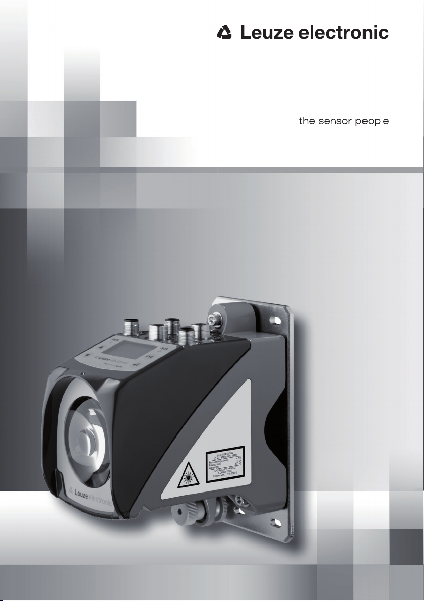
The main menus
ESC
Input of values
AMS 355i 120
Leuze electronic
GmbH & Co. KG
SW: V 1.3.0 HW:1
SN: -----------------------
Network information
Address: -Baudrate: ---- kbit/s
Status: Not Powered,...
IO1 LSR PLB
IO2 TMP ATT DNET
ERR
+ 87.000m
Parameter
Parameter handling
DeviceNet
Position value
I/O
Other
Device information - main menu
This menu item contains detailed information on
• device type,
• manufacturer,
• software and hardware version,
• serial number.
No entries can be made via the display.
Network information - main menu
Explanations of address, baud rate, status.
No entries can be made via the display.
Status- and measurement data main menu
• Display of status-, warning-, and error messages.
• Status overview of the switching inputs/outputs.
• Bar graph for the reception level.
• Activated interface.
• Measurement value.
No entries can be made via the display.
See "Indicators in the display" on page 38.
Parameter - main menu
• Configuration of the AMS
See "Parameter menu" on page 44.
100
<-|0123456789 save
Standard ----- Unit
63 | |
Language selection
o Deutsch
English
o Español
o Français
o Italiano
Service
Status messages
Diagnostics
Expanded diagnostics
Language selection - main menu
• Selection of the display language.
See "Language selection menu" on page 47.
Service - main menu
• Display of status messages.
• Display of diagnostic data.
No entries can be made via the display.
See "Service menu" on page 47.
Page 4

Table of contents
1 General information . . . . . . . . . . . . . . . . . . . . . . . . . . . . . . . . . . . . 5
1.1 Explanation of symbols . . . . . . . . . . . . . . . . . . . . . . . . . . . . . . . . . . . . . . . . . . . . . . . . . . . 5
1.2 Declaration of conformity . . . . . . . . . . . . . . . . . . . . . . . . . . . . . . . . . . . . . . . . . . . . . . . . . 5
1.3 Description of functions AMS 355i . . . . . . . . . . . . . . . . . . . . . . . . . . . . . . . . . . . . . . . . . . 6
2 Safety . . . . . . . . . . . . . . . . . . . . . . . . . . . . . . . . . . . . . . . . . . . . . . . 7
2.1 Intended use . . . . . . . . . . . . . . . . . . . . . . . . . . . . . . . . . . . . . . . . . . . . . . . . . . . . . . . . . . . 7
2.2 Foreseeable misuse. . . . . . . . . . . . . . . . . . . . . . . . . . . . . . . . . . . . . . . . . . . . . . . . . . . . . . 8
2.3 Competent persons . . . . . . . . . . . . . . . . . . . . . . . . . . . . . . . . . . . . . . . . . . . . . . . . . . . . . . 8
2.4 Disclaimer. . . . . . . . . . . . . . . . . . . . . . . . . . . . . . . . . . . . . . . . . . . . . . . . . . . . . . . . . . . . . . 9
2.5 Laser safety notices. . . . . . . . . . . . . . . . . . . . . . . . . . . . . . . . . . . . . . . . . . . . . . . . . . . . . . 9
3 Fast commissioning / operating principle . . . . . . . . . . . . . . . . . . . 12
3.1 Mounting the AMS 355i . . . . . . . . . . . . . . . . . . . . . . . . . . . . . . . . . . . . . . . . . . . . . . . . . . 12
3.1.1 Mounting the device . . . . . . . . . . . . . . . . . . . . . . . . . . . . . . . . . . . . . . . . . . . . . . . . . . . . . 12
3.1.2 Mounting the reflector. . . . . . . . . . . . . . . . . . . . . . . . . . . . . . . . . . . . . . . . . . . . . . . . . . . . 12
3.2 Connecting the voltage supply . . . . . . . . . . . . . . . . . . . . . . . . . . . . . . . . . . . . . . . . . . . . 13
3.3 Display . . . . . . . . . . . . . . . . . . . . . . . . . . . . . . . . . . . . . . . . . . . . . . . . . . . . . . . . . . . . . . . 13
3.4 AMS 355i on the DeviceNet . . . . . . . . . . . . . . . . . . . . . . . . . . . . . . . . . . . . . . . . . . . . . . 13
4 Specifications . . . . . . . . . . . . . . . . . . . . . . . . . . . . . . . . . . . . . . . . 14
4.1 Specifications of the laser measurement system . . . . . . . . . . . . . . . . . . . . . . . . . . . . . 14
4.1.1 General specifications AMS 355i . . . . . . . . . . . . . . . . . . . . . . . . . . . . . . . . . . . . . . . . . . . 14
4.1.2 Dimensioned drawing AMS 355i . . . . . . . . . . . . . . . . . . . . . . . . . . . . . . . . . . . . . . . . . . . 16
4.1.3 Type overview AMS 355i . . . . . . . . . . . . . . . . . . . . . . . . . . . . . . . . . . . . . . . . . . . . . . . . . 17
5 Installation and mounting . . . . . . . . . . . . . . . . . . . . . . . . . . . . . . . 18
5.1 Storage, transportation . . . . . . . . . . . . . . . . . . . . . . . . . . . . . . . . . . . . . . . . . . . . . . . . . . 18
5.2 Mounting the AMS 355i . . . . . . . . . . . . . . . . . . . . . . . . . . . . . . . . . . . . . . . . . . . . . . . . . . 19
5.2.1 Optional mounting bracket . . . . . . . . . . . . . . . . . . . . . . . . . . . . . . . . . . . . . . . . . . . . . . . . 21
5.2.2 Parallel mounting of the AMS 355i . . . . . . . . . . . . . . . . . . . . . . . . . . . . . . . . . . . . . . . . . . 22
5.2.3 Parallel mounting of AMS 355i and DDLS optical data transmission. . . . . . . . . . . . . . . . 23
5.3 Mounting the AMS 355i with laser beam deflector unit . . . . . . . . . . . . . . . . . . . . . . . . . 24
5.3.1 Mounting the laser beam deflector unit With integrated mounting bracket . . . . . . . . . . . 24
5.3.2 Dimensioned drawing of US AMS 01 deflector unit . . . . . . . . . . . . . . . . . . . . . . . . . . . . . 25
5.3.3 Mounting the US 1 OMS deflector unit without mounting bracket . . . . . . . . . . . . . . . . . 26
AMS 355i 1
Page 5

Table of contents
6 Reflectors . . . . . . . . . . . . . . . . . . . . . . . . . . . . . . . . . . . . . . . . . . . 27
6.1 General information . . . . . . . . . . . . . . . . . . . . . . . . . . . . . . . . . . . . . . . . . . . . . . . . . . . . .27
6.2 Description of the reflective tape. . . . . . . . . . . . . . . . . . . . . . . . . . . . . . . . . . . . . . . . . . . 27
6.2.1 Specifications of the self-adhesive foil . . . . . . . . . . . . . . . . . . . . . . . . . . . . . . . . . . . . . . . 28
6.2.2 Specifications of the reflective tape on a metal plate . . . . . . . . . . . . . . . . . . . . . . . . . . . .28
6.2.3 Dimensioned drawing of reflective tape on a metal plate . . . . . . . . . . . . . . . . . . . . . . . . . 29
6.2.4 Specifications of heated reflectors . . . . . . . . . . . . . . . . . . . . . . . . . . . . . . . . . . . . . . . . . . 30
6.2.5 Dimensioned drawing of heated reflectors . . . . . . . . . . . . . . . . . . . . . . . . . . . . . . . . . . . . 31
6.3 Selecting reflector sizes . . . . . . . . . . . . . . . . . . . . . . . . . . . . . . . . . . . . . . . . . . . . . . . . . . 32
6.4 Mounting the reflector . . . . . . . . . . . . . . . . . . . . . . . . . . . . . . . . . . . . . . . . . . . . . . . . . . . 33
6.4.1 General information . . . . . . . . . . . . . . . . . . . . . . . . . . . . . . . . . . . . . . . . . . . . . . . . . . . . . . 33
6.4.2 Mounting the reflector . . . . . . . . . . . . . . . . . . . . . . . . . . . . . . . . . . . . . . . . . . . . . . . . . . . .33
6.4.3 Table of reflector pitches . . . . . . . . . . . . . . . . . . . . . . . . . . . . . . . . . . . . . . . . . . . . . . . . . . 36
7 Electrical connection . . . . . . . . . . . . . . . . . . . . . . . . . . . . . . . . . . 37
7.1 Safety notices for the electrical connection . . . . . . . . . . . . . . . . . . . . . . . . . . . . . . . . . . 37
7.2 PWR – voltage supply / switching input/output . . . . . . . . . . . . . . . . . . . . . . . . . . . . . . . 38
7.3 DeviceNet BUS IN. . . . . . . . . . . . . . . . . . . . . . . . . . . . . . . . . . . . . . . . . . . . . . . . . . . . . . . 38
7.4 DeviceNet BUS OUT . . . . . . . . . . . . . . . . . . . . . . . . . . . . . . . . . . . . . . . . . . . . . . . . . . . . . 39
7.5 Service. . . . . . . . . . . . . . . . . . . . . . . . . . . . . . . . . . . . . . . . . . . . . . . . . . . . . . . . . . . . . . . .39
8 Display and control panel AMS 355i . . . . . . . . . . . . . . . . . . . . . . . 40
8.1 Structure of the control panel . . . . . . . . . . . . . . . . . . . . . . . . . . . . . . . . . . . . . . . . . . . . . 40
8.2 Status display and operation . . . . . . . . . . . . . . . . . . . . . . . . . . . . . . . . . . . . . . . . . . . . . . 40
8.2.1 Indicators in the display . . . . . . . . . . . . . . . . . . . . . . . . . . . . . . . . . . . . . . . . . . . . . . . . . . . 40
8.2.2 LED status displays . . . . . . . . . . . . . . . . . . . . . . . . . . . . . . . . . . . . . . . . . . . . . . . . . . . . . . 42
8.2.3 Control buttons . . . . . . . . . . . . . . . . . . . . . . . . . . . . . . . . . . . . . . . . . . . . . . . . . . . . . . . . . 43
8.3 Menu description . . . . . . . . . . . . . . . . . . . . . . . . . . . . . . . . . . . . . . . . . . . . . . . . . . . . . . .44
8.3.1 The main menus . . . . . . . . . . . . . . . . . . . . . . . . . . . . . . . . . . . . . . . . . . . . . . . . . . . . . . . . 44
8.3.2 Parameter menu . . . . . . . . . . . . . . . . . . . . . . . . . . . . . . . . . . . . . . . . . . . . . . . . . . . . . . . . 46
8.3.3 Language selection menu . . . . . . . . . . . . . . . . . . . . . . . . . . . . . . . . . . . . . . . . . . . . . . . . . 49
8.3.4 Service menu . . . . . . . . . . . . . . . . . . . . . . . . . . . . . . . . . . . . . . . . . . . . . . . . . . . . . . . . . . . 49
8.4 Operation. . . . . . . . . . . . . . . . . . . . . . . . . . . . . . . . . . . . . . . . . . . . . . . . . . . . . . . . . . . . . . 49
9 DeviceNet interface. . . . . . . . . . . . . . . . . . . . . . . . . . . . . . . . . . . . 52
9.1 General information on DeviceNet . . . . . . . . . . . . . . . . . . . . . . . . . . . . . . . . . . . . . . . . . . 52
9.1.1 Topology . . . . . . . . . . . . . . . . . . . . . . . . . . . . . . . . . . . . . . . . . . . . . . . . . . . . . . . . . . . . . . 52
2 AMS 355i
Page 6

Table of contents
9.1.2 Communication. . . . . . . . . . . . . . . . . . . . . . . . . . . . . . . . . . . . . . . . . . . . . . . . . . . . . . . . . 54
9.2 DeviceNet electrical connection . . . . . . . . . . . . . . . . . . . . . . . . . . . . . . . . . . . . . . . . . . . 55
9.3 Electrical data for the supply voltage – Data V+ and Data V- . . . . . . . . . . . . . . . . . . . . 56
9.4 DeviceNet address entry - MAC ID . . . . . . . . . . . . . . . . . . . . . . . . . . . . . . . . . . . . . . . . . 56
9.4.1 Entering the MAC ID (address) via the display . . . . . . . . . . . . . . . . . . . . . . . . . . . . . . . . . 56
9.5 EDS file - general info . . . . . . . . . . . . . . . . . . . . . . . . . . . . . . . . . . . . . . . . . . . . . . . . . . . 57
9.6 EDS file - detailed description. . . . . . . . . . . . . . . . . . . . . . . . . . . . . . . . . . . . . . . . . . . . . 59
9.6.1 Class 4 Assembly . . . . . . . . . . . . . . . . . . . . . . . . . . . . . . . . . . . . . . . . . . . . . . . . . . . . . . . 59
9.6.2 Class 1 Identity object . . . . . . . . . . . . . . . . . . . . . . . . . . . . . . . . . . . . . . . . . . . . . . . . . . . 62
9.6.3 Class 35 Position sensor object . . . . . . . . . . . . . . . . . . . . . . . . . . . . . . . . . . . . . . . . . . . . 64
9.6.4 Class 100 Display configuration . . . . . . . . . . . . . . . . . . . . . . . . . . . . . . . . . . . . . . . . . . . . 71
9.6.5 Class 101 Selection assembly . . . . . . . . . . . . . . . . . . . . . . . . . . . . . . . . . . . . . . . . . . . . . 72
9.6.6 Class 103 Switching inputs/outputs . . . . . . . . . . . . . . . . . . . . . . . . . . . . . . . . . . . . . . . . . 74
9.6.7 Class 104 Behavior in the case of error . . . . . . . . . . . . . . . . . . . . . . . . . . . . . . . . . . . . . . 77
9.6.8 Class 105 Velocity monitoring . . . . . . . . . . . . . . . . . . . . . . . . . . . . . . . . . . . . . . . . . . . . . 79
10 Diagnostics and troubleshooting . . . . . . . . . . . . . . . . . . . . . . . . . 82
10.1 Service and diagnostics in the display of the AMS 355i . . . . . . . . . . . . . . . . . . . . . . . . 82
10.1.1 Status messages . . . . . . . . . . . . . . . . . . . . . . . . . . . . . . . . . . . . . . . . . . . . . . . . . . . . . . . 82
10.1.2 Diagnostics . . . . . . . . . . . . . . . . . . . . . . . . . . . . . . . . . . . . . . . . . . . . . . . . . . . . . . . . . . . . 83
10.1.3 Expanded diagnostics . . . . . . . . . . . . . . . . . . . . . . . . . . . . . . . . . . . . . . . . . . . . . . . . . . . 83
10.2 General causes of errors . . . . . . . . . . . . . . . . . . . . . . . . . . . . . . . . . . . . . . . . . . . . . . . . . 83
10.2.1 Power LED . . . . . . . . . . . . . . . . . . . . . . . . . . . . . . . . . . . . . . . . . . . . . . . . . . . . . . . . . . . . 84
10.3 Interface errors. . . . . . . . . . . . . . . . . . . . . . . . . . . . . . . . . . . . . . . . . . . . . . . . . . . . . . . . . 84
10.3.1 Net LED. . . . . . . . . . . . . . . . . . . . . . . . . . . . . . . . . . . . . . . . . . . . . . . . . . . . . . . . . . . . . . . 84
10.4 Status display in the display of the AMS 355i . . . . . . . . . . . . . . . . . . . . . . . . . . . . . . . . 85
11 Type overview and accessories . . . . . . . . . . . . . . . . . . . . . . . . . . 87
11.1 Type key . . . . . . . . . . . . . . . . . . . . . . . . . . . . . . . . . . . . . . . . . . . . . . . . . . . . . . . . . . . . . . 87
11.2 type overview AMS 355i (DeviceNet) . . . . . . . . . . . . . . . . . . . . . . . . . . . . . . . . . . . . . . . 87
11.3 Overview of reflector types . . . . . . . . . . . . . . . . . . . . . . . . . . . . . . . . . . . . . . . . . . . . . . . 88
11.4 Accessories . . . . . . . . . . . . . . . . . . . . . . . . . . . . . . . . . . . . . . . . . . . . . . . . . . . . . . . . . . . 88
11.4.1 Accessory mounting bracket . . . . . . . . . . . . . . . . . . . . . . . . . . . . . . . . . . . . . . . . . . . . . . 88
11.4.2 Accessory deflector unit. . . . . . . . . . . . . . . . . . . . . . . . . . . . . . . . . . . . . . . . . . . . . . . . . . 88
11.4.3 Accessory M 12 connector . . . . . . . . . . . . . . . . . . . . . . . . . . . . . . . . . . . . . . . . . . . . . . . . 88
11.4.4 Accessory terminating resistor . . . . . . . . . . . . . . . . . . . . . . . . . . . . . . . . . . . . . . . . . . . . . 89
11.4.5 Accessory ready-made cables for voltage supply . . . . . . . . . . . . . . . . . . . . . . . . . . . . . . 89
11.4.6 Accessory ready-made cables for DeviceNet . . . . . . . . . . . . . . . . . . . . . . . . . . . . . . . . . 90
AMS 355i 3
Page 7

Table of contents
12 Maintenance . . . . . . . . . . . . . . . . . . . . . . . . . . . . . . . . . . . . . . . . . 92
12.1 General maintenance information . . . . . . . . . . . . . . . . . . . . . . . . . . . . . . . . . . . . . . . . . . 92
12.2 Repairs, servicing . . . . . . . . . . . . . . . . . . . . . . . . . . . . . . . . . . . . . . . . . . . . . . . . . . . . . . . 92
12.3 Disassembling, packing, disposing . . . . . . . . . . . . . . . . . . . . . . . . . . . . . . . . . . . . . . . . . 92
4 AMS 355i
Page 8
1 General information
U
L
US
C
LISTED
1.1 Explanation of symbols
The symbols used in this operating manual are explained below.
Attention!
This symbol precedes text messages which must strictly be observed. Failure to comply with
this information results in injuries to personnel or damage to the equipment.
Attention Laser!
This symbol warns of possible danger caused by hazardous laser radiation.
Notice!
This symbol indicates text passages containing important information.
1.2 Declaration of conformity
The AMS 355i absolute measuring optical laser measurement system was designed and
manufactured in accordance with applicable European directives and standards.
The AMS series is "UL LISTED" according to American and Canadian safety standards and
fulfills the requirements of Underwriter Laboratories Inc. (UL).
General information
Notice!
The Declaration of Conformity for these devices can be requested from the manufacturer.
The manufacturer of the product, Leuze electronic GmbH + Co. KG in D-73277 Owen/Teck,
possesses a certified quality assurance system in accordance with ISO 9001.
Leuze electronic AMS 355i 5
TNT 35/7-24V
Page 9
General information
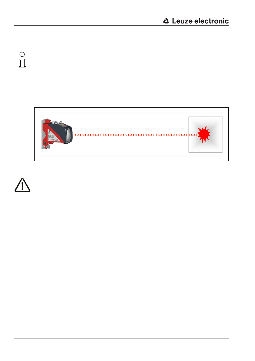
1.3 Description of functions AMS 355i
The AMS 355i optical laser measurement system calculates distances to fixed as well as
moving system parts. The distance to be measured is calculated according to the principle
of the propagation time of radiated light. Here, the light emitted by the laser diode is reflected
by a reflector onto the receiving element of the laser measurement system. The AMS 355i
uses the "propagation time" of the light to calculate the distance to the reflector. The high
absolute measurement accuracy of the laser measurement system and the fast integration
time are designed for position control applications.
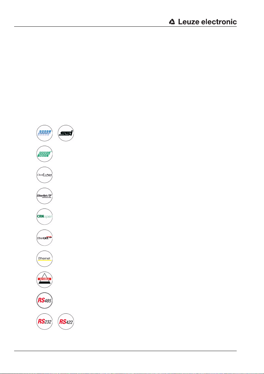
With the AMS 3xxi product series, Leuze electronic makes available a range of internationally relevant interfaces. Note that each interface version listed below corresponds to a
different AMS 3xxi model.
AMS 304i
AMS 348i
AMS 355i
AMS 358i
AMS 335i
AMS 338i
AMS 308i
AMS 384i
AMS 301i
AMS 300i
6 AMS 355i Leuze electronic
Page 10
2 Safety
This sensor was developed, manufactured and tested in line with the applicable safety standards. It corresponds to the state of the art.
2.1 Intended use
The AMS is an absolute measuring optical laser measurement system which allows
distance measurement of up to 300m against a reflector.
Areas of application
The AMS is designed for the following areas of application:
• Positioning of automated, moving plant components
• Travel and lifting axes of high-bay storage devices
• Repositioning units
• Gantry crane bridges and their trolleys
•Lifts
• Electroplating plants
CAUTION
Observe intended use!
Only operate the device in accordance with its intended use. The protection of per-
sonnel and the device cannot be guaranteed if the device is operated in a manner not
complying with its intended use.
Leuze electronic GmbH + Co. KG is not liable for damages caused by improper use.
Read the technical description before commissioning the device. Knowledge of this
technical description is an element of proper use.
Safety
NOTICE
Comply with conditions and regulations!
Observe the locally applicable legal regulations and the rules of the employer's liability
insurance association.
Attention
For UL applications, use is permitted exclusively in Class 2 circuits according to NEC
(National Electric Code).
Leuze electronic AMS 355i 7
TNT 35/7-24V
Page 11

Safety
2.2 Foreseeable misuse
Any use other than that defined under "Intended use" or which goes beyond that use is
considered improper use.
In particular, use of the device is not permitted in the following cases:
• Rooms with explosive atmospheres
• Circuits relevant to safety
• For medicinal purposes
NOTICE
Do not modify or otherwise interfere with the device.
Do not carry out modifications or otherwise interfere with the device.
The device must not be tampered with and must not be changed in any way.
The device must not be opened. There are no user-serviceable parts inside.
Repairs must only be performed by Leuze electronic GmbH + Co. KG.
2.3 Competent persons
Connection, mounting, commissioning and adjustment of the device must only be carried
out by competent persons.
Prerequisites for competent persons:
• They have a suitable technical education.
• They are familiar with the rules and regulations for occupational safety and safety at
work.
• They are familiar with the technical description of the device.
• They have been instructed by the responsible person on the mounting and operation
of the device.
Certified electricians
Electrical work must be carried out by a certified electrician.
Due to their technical training, knowledge and experience as well as their familiarity with
relevant standards and regulations, certified electricians are able to perform work on electrical systems and independently detect possible dangers.
In Germany, certified electricians must fulfill the requirements of accident-prevention regulations BGV A3 (e.g. electrician foreman). In other countries, there are respective regulations that must be observed.
8 AMS 355i Leuze electronic
Page 12
2.4 Disclaimer
Leuze electronic GmbH + Co. KG is not liable in the following cases:
• The device is not being used properly.
• Reasonably foreseeable misuse is not taken into account.
• Mounting and electrical connection are not properly performed.
• Changes (e.g., constructional) are made to the device.
2.5 Laser safety notices
ATTENTION LASER RADIATION – LASER CLASS 2
Never look directly into the beam!
The device satisfies the requirements of IEC 60825-1:2007 (EN 60825-1:2007) safety
regulations for a product in laser class 2 as well as the U.S. 21 CFR 1040.10 regulations
with deviations corresponding to "Laser Notice No. 50" from June 24th, 2007.
Never look directly into the laser beam or in the direction of reflecting laser beams.
If you look into the beam path over a longer time period, there is a risk of injury to the
retina.
Do not point the laser beam of the device at persons!
Interrupt the laser beam using a non-transparent, non-reflective object if the laser
beam is accidentally directed towards a person.
When mounting and aligning the device, avoid reflections of the laser beam off reflec-
tive surfaces!
CAUTION! The use of operating or adjusting devices other than those specified here
or carrying out of differing procedures may lead to dangerous exposure to radiation.
Adhere to the applicable legal and local regulations regarding protection from laser
beams.
The device must not be tampered with and must not be changed in any way.
There are no user-serviceable parts inside the device.
Repairs must only be performed by Leuze electronic GmbH + Co. KG.
Safety
TNT 35/7-24V
Leuze electronic AMS 355i 9
Page 13

Safety
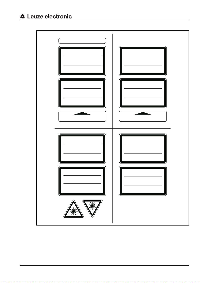
A Laser aperture
B Laser warning sign
C Laser information sign with laser parameters
A B
C
NOTICE
Affix laser information and warning signs!
Laser information and warning signs are attached to the device (see figure 2.1):
In addition, self-adhesive laser warning and information signs (stick-on labels) are supplied
in several languages (see figure 2.2).
Affix the laser information sheet to the device in the language appropriate for the place
of use.
When using the device in the US, use the stick-on label with the "Complies with
21 CFR 1040.10" notice.
Affix the laser information and warning signs near the device if no signs are attached
to the device (e.g., because the device is too small) or if the attached laser information
and warning signs are concealed due to the installation position.
Affix the laser information and warning signs so that they are legible without exposing
the reader to the laser radiation of the device or other optical radiation.
Figure 2.1: Laser apertures, laser warning signs
10 AMS 355i Leuze electronic
Page 14
AVOID EXPOSURE – LASER RADIATION
IS EMITTED FROM THIS APERTURE
EXPOSITION DANGEREUSE – UN RAYONNEMENT
LASER EST ÉMIS PAR CETTE OUVERTURE
LASERSTRAHLUNG
NICHT IN DEN STRAHL BLICKEN
LASER KLASSE 2
DIN EN 60825-1:2008-05
Max. Leistung (peak):
Impulsdauer:
Wellenlänge:
RADIAZIONE LASER
NON FISSARE IL FASCIO
APARRECCHIO LASER DI CLASSE 2
EN 60825-1:2007
Potenza max. (peak):
Durata dell'impulso:
Lunghezza d'onda:
LASER RADIATION
DO NOT STARE INTO BEAM
CLASS 2 LASER PRODUCT
EN 60825-1:2007
Maximum Output (peak):
Pulse duration:
Wavelength:
RAYONNEMENT LASER
NE PAS REGARDER DANS LE FAISCEAU
APPAREIL À LASER DE CLASSE 2
EN 60825-1:2007
Puissance max. (crête):
Durée d`impulsion:
Longueur d`onde:
RADIACIÓN LÁSER
NO MIRAR FIJAMENTE AL HAZ
PRODUCTO LÁSER DE CLASE 2
EN 60825-1:2007
Potencia máx. (peak):
Duración del impulso:
Longitud de onda:
RADIAÇÃO LASER
NÃO OLHAR FIXAMENTE O FEIXE
EQUIPAMENTO LASER CLASSE 2
EN 60825-1:2007
Potência máx. (peak):
Período de pulso:
Comprimento de onda:
LASER RADIATION
DO NOT STARE INTO BEAM
CLASS 2 LASER PRODUCT
IEC 60825-1:2007
Complies with 21 CFR 1040.10
Maximum Output (peak):
Pulse duration:
Wavelength:
䉏⏘戟⺓
▎䦃展⏘㧮
伊䉏⏘ℶ❐
GB7247.1-2012
㦏⮶戢⒉᧤⽿⋋᧥
厘⑁㖐兼㢅梃
㽱栎
4 mW
18 μs
655 nm
4 mW
18 μs
655 nm
4 mW
18 μs
655 nm
4 mW
18
μ
s
655 nm
4 mW
18 μs
655 nm
4 mW
18 μs
655 nm
4 mW
18 μs
655 nm
4 mW
18 μs
655 nm
50125612-01
Safety
Figure 2.2: Laser warning and information signs – supplied stick-on labels
TNT 35/7-24V
Leuze electronic AMS 355i 11
Page 15
Fast commissioning / operating principle
3 Fast commissioning / operating principle
Notice!
Below, you will find a short description for the initial commissioning of the AMS 355i.
Detailed explanations for the listed points can be found throughout the handbook.
3.1 Mounting the AMS 355i
The AMS 355i and the corresponding reflector are mounted on two mutually opposing,
plane-parallel, flat walls.
Figure 3.1: Schematic illustration of mounting
Attention!
For error-free position measurement, there must be an unobstructed line-of-sight between
the AMS 355i and the reflector.
3.1.1 Mounting the device
The laser is mounted on a vertical wall using 4 screws (M5).
Alignment is performed using 2 adjustment screws. Adjust so that the laser light spot is
positioned at the center of the reflector. The alignment is to be secured with the knurled nut
and locked with the M5 nut.
Further information can be found in chapter 5.2 and chapter 5.3.
3.1.2 Mounting the reflector
The reflector is mounted on a vertical wall with 4 screws (M5). The reflector is angled using
the included shims. Incline the reflector by approx. 1°.
Detailed information can be found in chapter 6.4.
12 AMS 355i Leuze electronic
Page 16
Fast commissioning / operating principle
3.2 Connecting the voltage supply
The laser measurement system is connected using M12 connectors. The voltage supply is
connected via the PWR M12 connection.
Detailed information can be found in chapter 7.
3.3 Display
Once the laser measurement system is supplied with voltage, the device status as well as
the measured position values can be read on the display. The display automatically switches
to the display of the measurement values.
Use the up/down buttons to the left of the display to read and change a wide range
of data and parameters.
Depending on connected interface, the network address must be configured via the display.
Detailed information can be found in chapter 8.
3.4 AMS 355i on the DeviceNet
Install the EDS file corresponding to the AMS 355i … in your planning tool/the control
(e.g., RS network).
Notice!
You can find the EDS file at
The AMS 355i is configured in the planning tool/control by means of the EDS file. If the
AMS 355i has been assigned an address in the planning tool, the address is to be set on
the AMS 355i via the control panel/display. Only if the addresses are the same between the
AMS 355i and the control can communication be established.
After all parameters have been set in the planning tool/control, the download to the
AMS 355i takes place. The set parameters are now stored on the AMS 355i.
Afterwards, all AMS 355i parameters should be stored via upload in the control. This aids
in retaining the parameters during device exchanges, as they a re now also stored centrally
in the control.
Each time a connection is established between the control and the AMS 355i, these
parameters are now transferred again to the AMS 355i. Note that this function must be
supported by the control.
The DeviceNet baud rate is defined for the entire network in the planning tool/control.
The baud rate is set on the AMS 355i via the control panel/display.
Only if the baud rates are the same is communication with the AMS 355i possible.
Detailed information can be found in chapter 9.
www.leuze.com.
TNT 35/7-24V
Leuze electronic AMS 355i 13
Page 17

Specifications
4 Specifications
4.1 Specifications of the laser measurement system
4.1.1 General specifications AMS 355i
Measurement data AMS 355i 40 (H) AMS 355i 120 (H) AMS 355i 200 (H) AMS 355i 300 (H)
Measurement range 0.2 … 40m 0.2 … 120m 0.2 … 200m 0.2 … 300m
Accuracy ± 2mm ± 2mm ± 3mm ± 5mm
Consistency
Light spot diameter ≤ 40mm ≤ 100mm ≤ 150 mm ≤ 225 mm
Measurement value output
Integration time 8ms
Resolution adjustable, see chapter of the individual interfaces
Temperature drift ≤ 0.1 mm/K
Ambient temperature sensitivity 1ppm/K
Air pressure sensitivity 0.3ppm/hPa
Tra ve rs e r at e ≤ 10 m/s
Electrical data
Supply voltage Vin
Supply voltage data V+ 11 … 25VDC
Supply voltage data V- reference potential
Current consumption AMS 355i
at Data V+
Current consumption without device heating: ≤ 250 mA / 24V DC
Optical data
Transmitter laser diode, red light, wavelength 650 … 690nm
Laser class 2 acc. to EN 60825-1, CDRH
Interfaces
DeviceNet 125kbit/s (default) / 250kbit/s / 500 kbit/s
Vendor ID 524
Device type 34
Position sensor type 8
Operating and display elements
Keyboard 4 buttons
Display monochromatic graphical display, 128 x 64 pixels
LED 2 LEDs, two-colored
1)
0.3mm 0.5mm 0.7mm 1.0mm
1.7ms
2)
18 … 30V DC
max. 80mA at 11VDC
(for supplying the bus transceiver, not for the complete device)
with device heating: ≤ 500 mA / 24VDC
/ 20C
Dec
/ 22H (encoder)
Dec
/ 8H (absolute encoder)
Dec
H
14 AMS 355i Leuze electronic
Page 18

Specifications
Inputs/outputs
Quantity
Input
Output
Mechanical data
Housing cast zinc and aluminum
Optics glass
Weight approx. 2.45kg
Protection class
Environmental conditions
Operating temperature
without device heating
with device heating
Storage temperature -30°C … +70°C
Air humidity max. 90% rel. humidity, non-condensing
Mechanical/electrical loading capacity
Vibrations acc. to EN 60068-2-6
Noise acc. to EN 60060-2-64
Shock acc. to EN 60068-2-27
EMC
1) Statistical error: 1 sigma; minimum switch-on time: 2min.
2) For UL applications: only for use in "Class 2" circuits acc. to NEC.
3) With screwed-on M12 plugs or mounted caps.
4) With devices with heating, the switch on/off area of the internal heating can be extended to prevent
condensation from forming. A 100% prevention of the formation of condensation cannot be guaranteed due to the limited heating capacity of the AMS 355i.
5) This is a Class A product. In a domestic environment this product may cause radio interference, in
which case the operator may be required to take adequate measures.
acc. to EN 61000-6-2 and EN 61000-6-4
2, programmable
protected against polarity reversal
max. 60mA, short-circuit proof
IP 65 acc. to EN 60529
3)
-5°C … +50°C
-30°C…+50°C
4)
5)
The AMS 355i is designed in accordance with safety class III for supply with
PELV (protective extra-low voltage).
Leuze electronic AMS 355i 15
TNT 35/7-24V
Page 19
Specifications
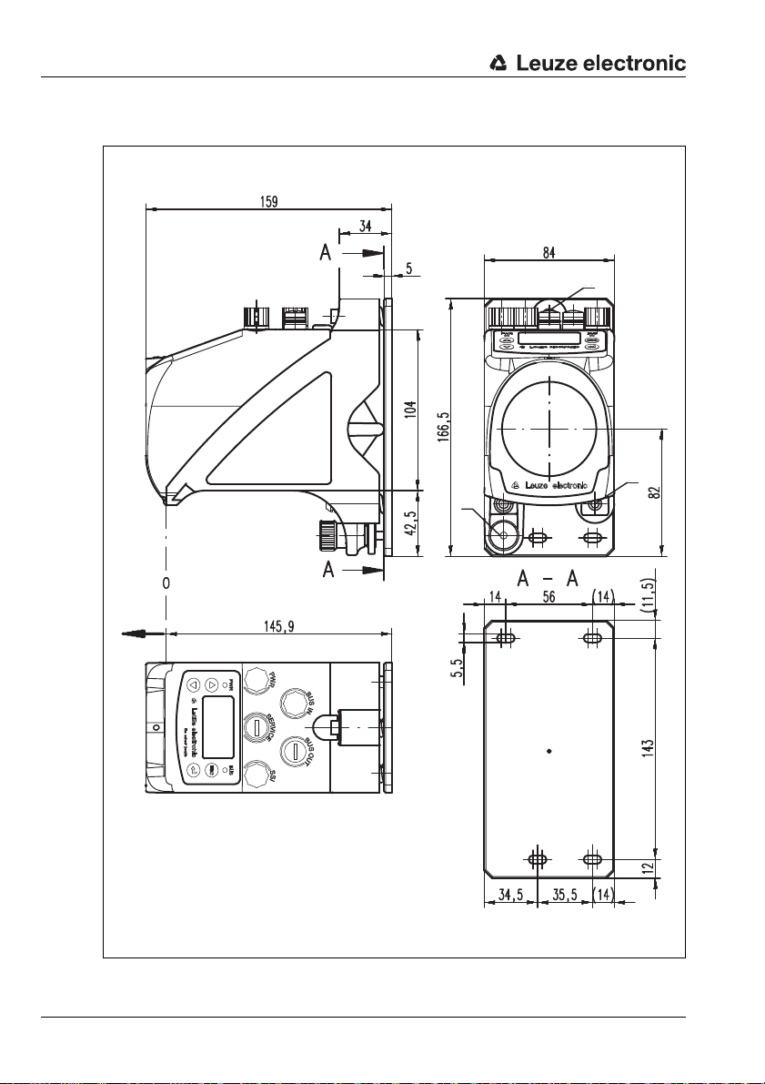
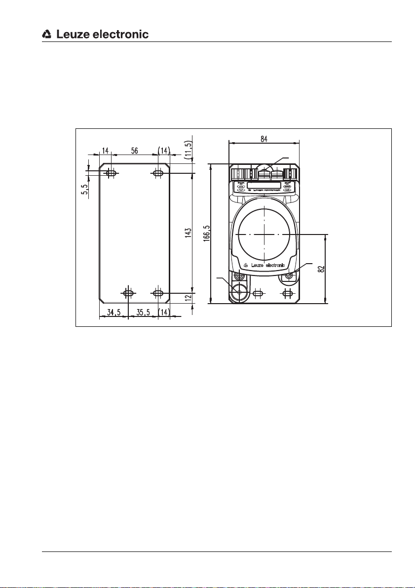
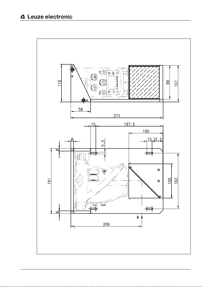
A M5 screw for alignment
B Knurled nut with WAF4
hexagon socket and M5 nut for securing
C Optical axis
D Zero point of the distance to be measured
A
B
D
A
C
4.1.2 Dimensioned drawing AMS 355i
16 AMS 355i Leuze electronic
Figure 4.1: Dimensioned drawing AMS 355i
Page 20

4.1.3 Type overview AMS 355i
AMS 355i (DeviceNet)
Type designation Description Part no.
AMS 355i 40 40m operating range, DeviceNet interface 50113717
AMS 355i 120 120m operating range, DeviceNet interface 50113718
AMS 355i 200 200m operating range, DeviceNet interface 50113719
AMS 355i 300 300m operating range, DeviceNet interface 50113720
AMS 355i 40 H 40m operating range, DeviceNet interface, integrated heating 50113721
AMS 355i 120 H 120m operating range, DeviceNet interface, integrated heating 50113722
AMS 355i 200 H 200m operating range, DeviceNet interface, integrated heating 50113723
AMS 355i 300 H 300m operating range, DeviceNet interface, integrated heating 50113724
Table 4.1: Type overview AMS 355i
Specifications
Leuze electronic AMS 355i 17
TNT 35/7-24V
Page 21
Installation and mounting
5 Installation and mounting
5.1 Storage, transportation
Attention!
When transporting or storing, package the device so that it i s prote cted against collision and
humidity. Optimum protection is achieved when using the original packaging. Heed the required environmental conditions specified in the technical data.
Unpacking
Check the packaging for any damage. If damage is found, notify the post office or shipping
agent as well as the supplier.
Check the delivery contents using your order and the delivery papers:
• Delivered quantity
• Device type and model as indicated on the nameplate
• Brief manual
The name plate provides information as to what AMS 355i type your device is. For specific
information, please refer to chapter 11.2.
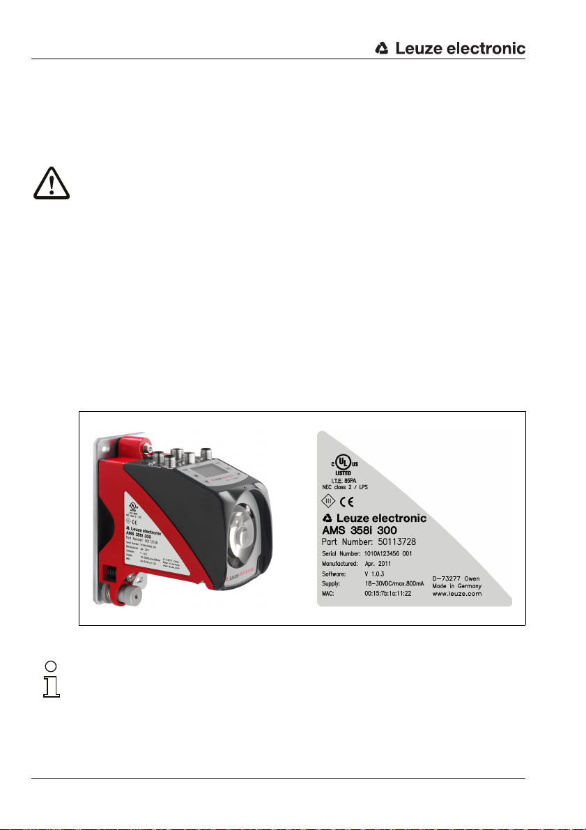
Name plates
Figure 5.1: Device name plate using the AMS 300i as an example
Notice!
Please note that the shown name plate is for illustration purposes only; the contents do not
correspond to the original.
Save the original packaging for later storage or shipping.
18 AMS 355i Leuze electronic
Page 22
If you have any questions concerning your shipment, please contact your supplier or your
A M5 screw for align-
ment
B Knurled nut and nut
with WAF4 hexagon
socket for securing
C Optical axis
A
B
A
C
local Leuze electronic sales office.
Observe the applicable local regulations when disposing of the packaging materials.
5.2 Mounting the AMS 355i
Installation and mounting
Figure 5.2: Mounting the device
The AMS 355i and the corresponding reflector are mounted on two mutually opposing,
plane-parallel, flat walls or system parts. For error-free position measurement, there must
be an unobstructed line-of-sight connection between the AMS 355i and the reflector.
Use M5 screws to fasten the laser measurement system. Secure the screws with a toothed
lock washer to protect against loosening caused by vibrations.
Leuze electronic AMS 355i 19
TNT 35/7-24V
Page 23
Installation and mounting
Aligning the laser light spot in the center of the reflector
The laser light spot has to be aligned so that it always hits the center of the opposing
reflector, both at close range as well as at the maximum measurement distance. To align,
use the two M5 Allen screws ("A" in figure 5.2). When aligning please ensure that the
knurled nut and the lock nut ("B" in figure 5.2) are opened wide.
Attention!
To prevent the laser measurement system from moving out of alignment during continuous
operation, subsequently hand-tighten the knurled nut and counterlock with the nut with
WAF4 hexagon socket ("B" in figure 5.2). Knurled nut and nut must not be tightened until
alignment has been completed.
Attention!
The device must not be opened. Failure to comply will render the guarantee void. Warranted
features cannot be guaranteed after the device has been opened.
20 AMS 355i Leuze electronic
Page 24
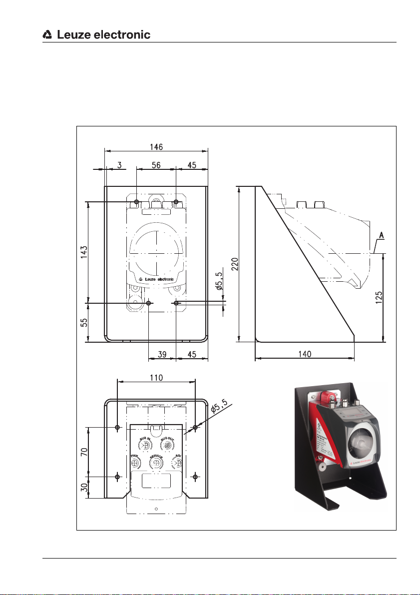
5.2.1 Optional mounting bracket
A Laser beam
A mounting bracket for mounting the AMS 355i on a flat, horizontal surface is available as
an optional accessory.
Type designation: MW OMS/AMS 01
Part no.: 50107255
Installation and mounting
Leuze electronic AMS 355i 21
TNT 35/7-24V
Figure 5.3: Optional mounting bracket
Page 25
Installation and mounting
X
Reflector 1 Reflector 2
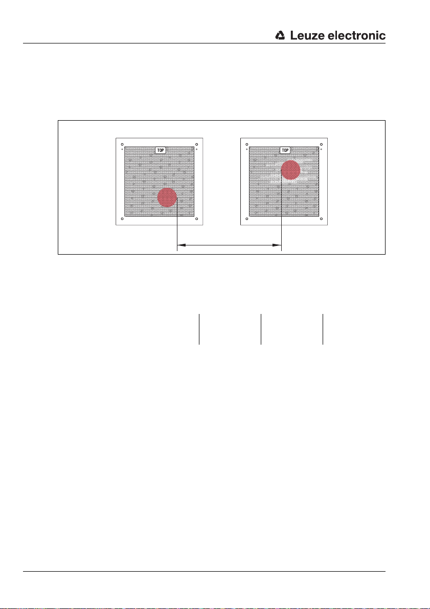
5.2.2 Parallel mounting of the AMS 355i
Definition of the term "parallel spacing"
As shown in figure 5.4, dimension X describes the "parallel spacing" of the inner edges of
the two laser light spots on the reflector.
Figure 5.4: Minimum parallel spacing X between adjacent AMS 355i
The diameter of the light spot increases with distance.
AMS 355i 40 (H) AMS 355i 120 (H) AMS 355i 200 (H) AMS 355i 300 (H)
Max. measurement distance
Light spot diameter ≤ 40mm ≤ 100mm ≤ 150mm ≤ 225 mm
Thus, the center-to-center spacing of the two AMS 355i devices with respect to one another
can be calculated as a function of the maximum measurement distance.
To define the minimum parallel spacing between two AMS 355i, it is necessary to distinguish
between three different arrangements of AMS 355i and reflectors.
40m 120m 200m 300m
The AMS 355i are mounted stationary and in parallel on one plane. Both reflectors move independently of one another at different distances to the AMS 355i.
Minimum parallel spacing X of the two laser light spots:
X = 100mm + (max. measurement distance in mm x 0.01)
The AMS 355i are mounted stationary and in parallel on one plane. Both reflectors move in parallel at the same distance to the AMS 355i.
Measurement distance up to 120m: minimum parallel spacing X ≥ 600mm
Measurement distance up to 200m: minimum parallel spacing X ≥ 750mm
Measurement distance up to 300m: minimum parallel spacing X ≥ 750mm
22 AMS 355i Leuze electronic
Page 26

Installation and mounting
The reflectors are mounted stationary and in parallel on one plane.
Both AMS 355i move independently of one another at different or the same distances to the reflectors.
Measurement distance up to 120 m: minimum parallel spacing X ≥ 600 mm
Measurement distance up to 200 m: minimum parallel spacing X ≥ 750 mm
Measurement distance up to 300 m: minimum parallel spacing X ≥ 750 mm
Notice!
Please note that when the AMS 355i are mounted in a mobile manner, travel tolerances could
cause the two laser light spots to move towards each other.
Take the travel tolerances of the vehicle into account when defining the parallel spacing of
adjacent AMS 355i.
5.2.3 Parallel mounting of AMS 355i and DDLS optical data transmission
The optical data transceivers of the DDLS series and the AMS 355i do not interfere with one
another. Depending on the size of the used reflector, the DDLS can be mounted with a
minimum parallel spacing of 100mm to the AMS 355i. The parallel spacing is independent
of the distance.
Leuze electronic AMS 355i 23
TNT 35/7-24V
Page 27
Installation and mounting
5.3 Mounting the AMS 355i with laser beam deflector unit
General information
The two available deflector units are used for the 90° deflection of the laser beam,
see "Accessory deflector unit" on page 88.
Attention!
The deflector units are designed for a maximum range of 40m.
Longer distances on request.
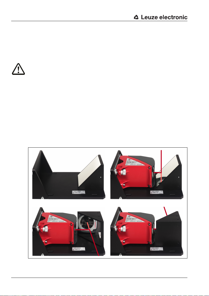
5.3.1 Mounting the laser beam deflector unit With integrated mounting bracket
The AMS 355i is screwed onto the mechanism of the US AMS 01 deflector unit. The mirror
can be mounted for three deflection directions:
1. Upward beam deflection
2. Beam deflection to the left
3. Beam deflection to the right
The deflector unit is mounted on plane-parallel, flat walls or plant components. For errorfree position measurement, there must be an interruption-free line-of-sight between the
AMS 355i… and the deflection mirror as well as between the mirror and the reflector.
Use the M5 screws to mount the deflector unit. Secure the screws with a toothed lock
washer to protect against loosening caused by vibrations.
Figure 5.5: Mounting variants of the US AMS 01 laser beam deflector unit
24 AMS 355i Leuze electronic
Page 28
Installation and mounting
A Laser beam
5.3.2 Dimensioned drawing of US AMS 01 deflector unit
Leuze electronic AMS 355i 25
TNT 35/7-24V
Figure 5.6: Dimensioned drawing of US AMS 01 deflector unit
Page 29
Installation and mounting
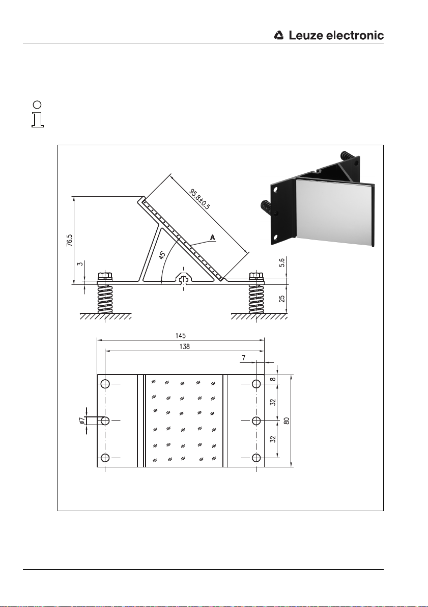
A Mirror
Height of the spring in
non-preloaded state
5.3.3 Mounting the US 1 OMS deflector unit without mounting bracket
The US 1 OMS deflector unit and the AMS 355i are mounted separately.
Notice!
When mounting, make certain that the laser light spot of the AMS 355i is aligned in the center
of the deflection mirror.
Figure 5.7: Photo and dimensioned drawing of the US 1 OMS deflector unit
Alignment of the laser light spot on the reflector is performed as described in chapter 5.2.
26 AMS 355i Leuze electronic
Page 30

6 Reflectors
6.1 General information
The AMS 355i measures distances against a reflective tape specified by Leuze electronic.
All provided specifications for the AMS 355i, such as the operating range or accuracy, can
only be achieved with the reflective tape specified by Leuze electronic.
The reflective tapes are available as adhesive tapes, affixed to a metal plate and with an
integrated heater especially for use at low temperatures. Reflective tapes with heating have
the designation "Reflective tape …x…-H", where "H" is an abbreviation for the heating
variant.
The reflective tapes/reflectors must be ordered separately. The choice of size is left to the
user. In chapter 6.3, recommendations on reflector size are provided as a function of the
distance that is to be measured. In any case, the user must check to determine whether the
recommendation is suitable for the respective application.
6.2 Description of the reflective tape
The reflective tape consists of a white, microprism-based reflective material. The microprisms are protected with a highly transparent, hard protective layer.
Under certain circumstances, the protective layer may lead to surface reflections. The
surface reflections can be directed past the AMS 355i by positioning the reflective tape at
a slight incline. The inclination of the reflective tape/reflectors is described in chapter 6.4.2.
The required pitch can be found in table 6.1 "Reflector pitch resulting from spacer sleeves"
on page 36.
The reflective tapes are provided with a protective fo il that ca n easily be p ulled off . This mus t
be removed from the reflector before the complete system is put into operation.
Reflectors
Leuze electronic AMS 355i 27
TNT 35/7-24V
Page 31

Reflectors
6.2.1 Specifications of the self-adhesive foil
Part
Type designation
Part no. 50104361 50104362 50108988
Foil size 200x 200mm 500 x500 mm 914 x914 mm
Recommended application temperature for adhesive tape
Temperature resistance,
affixed
Mounting surface The mounting surface must be clean, dry and free of grease.
Cutting the tape Cut with a sharp tool, always on the side of the prism structure.
Cleaning
Storing the foil Store in a cool and dry place.
Reflective tape
200x200-S
Do not use any agents that act with a grinding effect. A conventional household
detergent can be used as a cleaning agent. Rinse with clear water and dry the
6.2.2 Specifications of the reflective tape on a metal plate
The reflective tape is affixed to a metal plate. Included with the metal plate are spacers for
positioning at an incline - for avoiding surface reflections - (see chapter 6.4.2 "Mounting the
reflector").
Reflective tape
500x500-S
+5°C … +25 °C
-40°C…+80°C
surface.
Reflective tape
914x914-S
Part
Type designation
Part no. 50104364 50104365 50104366
Foil size 200x 200mm 500 x500 mm 914 x914 mm
Outer dimensions of the
metal plate
Weight 0.8kg 4kg 25kg
Cleaning
Storing the reflector Store in a cool and dry place.
28 AMS 355i Leuze electronic
Reflective tape
200x200-M
250x 250mm 550 x550 mm 964x964 mm
Do not use any agents that act with a grinding effect. A conventional household
detergent can be used as a cleaning agent. Rinse with clear water and dry the
Reflective tape
500x500-M
surface.
Reflective tape
914x914-M
Page 32

6.2.3 Dimensioned drawing of reflective tape on a metal plate
Always align the TOP marking
with the AMS connections!
(chapter 6.4.2)
Figure 6.1: Dimensioned drawing of reflectors
Part Reflective tape (mm) Reflector plate (mm)
xL yL XL YL L
Reflective tape 200x200-M 200 200 250 250 214
Reflective tape 500x500-M 500 500 550 550 514
Reflective tape 914x914-M 914 914 964 964 928
Reflectors
Leuze electronic AMS 355i 29
TNT 35/7-24V
Page 33

Reflectors
6.2.4 Specifications of heated reflectors
The reflective tape is affixed to a heated, thermally insulated base. The insulation results in
a very high energetic efficiency.
Only the reflective tape is kept at the specified temperature by the integrated heater.
Through the insulation on the back, the generated heat cannot be transferred via the steel
construction. Energy costs are greatly reduced in the case of continuous heating.
Type designation
Part no. 50115020 50115021 50115022
Voltage supply 230VAC
Power 100W 600W 1800 W
Current consumption ~ 0.5A ~ 3A ~ 8A
Length of the supply line 2 m
Size of the reflective tape 200 x200 mm 500 x500 mm 914x914mm
Outer dimensions of the base
material
Weight 0.5kg 2.5 kg 12 kg
Temperature control
Switch-on temperature ~ 5°C
Switch-off temperature ~ 20°C
Operating temperature -30°C … +70°C
Storage temperature -40°C … +80°C
Air humidity Max. 90%, non-condensing.
Cleaning
Storing the reflector Store in a cool and dry place.
Reflective tape
200x200-H
250x 250mm 550x 550mm 964x 964mm
Controlled heating with the following switch-on and switch-off tempera-
Do not use any agents that act with a grinding effect. A conventional household detergent can be used as a cleaning agent. Rinse with clear water and
Part
Reflective tape
500x500-H
tures, measured at the reflector surface.
dry the surface.
Reflective tape
914x914-H
30 AMS 355i Leuze electronic
Page 34

6.2.5 Dimensioned drawing of heated reflectors
18
6,5
2
L ± 0,5
XL ± 1
TOP
6
2000
115
90
XL ± 1
yL ± 1
L ± 0,5
YL ± 1
Always align the TOP marking
with the AMS connections!
(chapter 6.4.2)
Connection hood
Reflective tape
Si cable
3 x 0.75mm²
Reflectors
Figure 6.2: Dimensioned drawing of heated reflectors
Part Reflective tape (mm) Insulated base plate (mm)
Reflective tape 200x200-H 200 200 250 250 214
xL yL XL YL L
Reflective tape 500x500-H 500 500 550 550 514
Reflective tape 914x914-H 914 914 964 964 928
Leuze electronic AMS 355i 31
TNT 35/7-24V
Page 35

Reflectors
6.3 Selecting reflector sizes
Depending on system design, the reflector can be mounted so that it travels on the vehicle
or it can be mounted at a fixed location.
Attention!
The reflector sizes shown below are a recommendation from Leuze electronic for on-vehicle
mounting of the AMS 355i. For stationary mounting of the AMS 355i, a smaller reflector is
generally sufficient for all measurement distances.
On the basis of the system planning and design, always check whether mechanical travel
tolerances may require the use of a reflector larger than that which is recommended. This
applies, in particular, when the laser measurement system is mounted on a vehicle. During
travel, the laser beam must reach the reflector without interruption. For on-vehicle mounting
of the AMS 355i, the reflector size must accommodate any travel tolerances that may arise
and the associated "wandering" of the light spot on the reflector.
Overview of reflector types
AMS 355i selection
(Operating range in m)
AMS 355i 40 (max. 40m) 200x 200mm Reflective tape 200x200-S
AMS 355i 120 (max. 120m) 500x500mm Reflective tape 500x500-S
AMS 355i 200 (max. 200m) 749x 914mm
AMS 355i 300 (max. 300m) 749x 914mm
Recommended reflector sizes
Recommended
reflector size
(H x W)
914x 914mm
914x 914mm
Type designation
…-S = Self-adhesive
…-M = metal plate
…-H = heating
Reflective tape 200x200-M
Reflective tape 200x200-H
Reflective tape 500x500-M
Reflective tape 500x500-H
Reflective tape 749x914-S
Reflective tape 914x914-M
Reflective tape 914x914-S
Reflective tape 914x914-H
Reflective tape 749x914-S
Reflective tape 914x914-M
Reflective tape 914x914-S
Reflective tape 914x914-H
Part no.
50104361
50104364
50115020
50104362
50104365
50115021
50104363
50104366
50108988
50115022
50104363
50104366
50108988
50115022
32 AMS 355i Leuze electronic
Page 36

6.4 Mounting the reflector
6.4.1 General information
Self-adhesive reflective tapes
The reflective tapes of the "Reflective tape …x…-S" self-adhesive series must be affixed
to a flat, clean and grease-free surface. We recommend using a separate metal plate, which
is to be provided on-site.
As described in table 6.1, the reflective tape must be angled.
Reflective tapes on metal
The reflective tapes of the "Reflective tape …x…-M" series are provided with corresponding
mounting holes. Spacer sleeves are provided in the packet for achieving the necessary pitch
angle. For further information see table 6.1.
Heated reflectors
The reflective tapes of the "Reflective tape ...x...-H" series are provided with corresponding
mounting holes. Due to the voltage supply affixed on the rear, the reflector cannot be
mounted flat. Included in the package are four distance sleeves in two different lengths. Use
the distance sleeves to achieve a base separation to the wall as well as the necessary pitch
for avoiding surface reflection. For further information see table 6.1.
The reflector is provided with a 2m-long connection cable for supplying with 230V AC.
Connect the cable to the closest power outlet. Observe the current consumptions listed in
the specifications.
Reflectors
Attention!
Connection work must be carried out by a certified electrician.
6.4.2 Mounting the reflector
The combination of laser measurement system and reflective tape/reflector is mounted so
that the laser light spot hits the tape as centered as possible and without interruption.
For this purpose, use the alignment elements provided on the AMS 355i… (see chapter 5.2
"Mounting the AMS 355i"). If necessary, remove the protective foil from the reflector.
Attention!
The "TOP" label mounted on the reflectors should be aligned the same as the connections
of the AMS 355i.
Example:
If the AMS 355i is mounted so that the M12 connections are on the top, the "TOP" label of
the reflector is also on the top. If the AMS 355i is mounted so that the M12 connections are
on the side, the "TOP" label of the reflector is also on the side.
Leuze electronic AMS 355i 33
TNT 35/7-24V
Page 37

Reflectors
Pitch approx. 1°
Direct reflection from the
triad structure
Deflected surface reflection due to
the pitch of the reflective tape
Pitch approx. 1°
Spacer sleeves
Notice!
The reflector must be angled. To do this, use the spacer sleeves. Angle the reflectors so that
the surface reflections of the foil seal are deflected to the left, right or upwards, chapter
6.4.3 gives the correct pitch with respect to the reflector size and, thus, the length of the
spacers.
Reflective tapes …-S and …-M
Figure 6.3: Reflector mounting
Figure 6.4: Pitch of the reflector
34 AMS 355i Leuze electronic
Page 38

Reflective tapes …-H
Pitch approx. 1°
Deflected surface reflection due to
the pitch of the reflective tape
Direct reflection from the
triad structure
Pitch approx. 1°
Spacer sleeves
Figure 6.5: Mounting of heated reflectors
Reflectors
Figure 6.6: Pitch of the heated reflector
Leuze electronic AMS 355i 35
TNT 35/7-24V
Page 39

Reflectors
6.4.3 Table of reflector pitches
Reflector type Pitch resulting from spacer sleeves
Reflective tape 200x200-S
Reflective tape 200x200-M
Reflective tape 200x200-H 2x15mm 2x20mm
Reflective tape 500x500-S
Reflective tape 500x500-M
Reflective tape 500x500-H 2x15mm 2x25mm
Reflective tape 749x914-S 2x20mm
Reflective tape 914x914-S
Reflective tape 914x914-M
Reflective tape 914x914-H 2x15mm 2x35mm
1) Spacer sleeves are included in the delivery contents of reflective tape …-M and …-H
Table 6.1: Reflector pitch resulting from spacer sleeves
Notice!
Reliable function of the AMS 355i and, thus, max. operating range and accuracy can only
be achieved with the reflective tape specified by Leuze electronic. No function can be guaranteed if other reflectors are used!
2x5mm
2x10mm
2x20mm
1)
36 AMS 355i Leuze electronic
Page 40

7 Electrical connection
BUS IN
M12 connector
(A-coded)
PWR / IOs
M12 connector
(A-coded)
BUS OUT
M12 socket
(A-coded)
1)
Leuze SERVICE
M12 socket
(A-coded)
The AMS 355i laser measurement systems are connected using variously coded M 12
connectors. This ensures unique connection assignments.
Notice!
The corresponding mating connectors and ready-made cables are available as accessories
for all cables. For further information, see chapter 11 "Type overview and accessories".
Figure 7.1: Connections of the AMS 355i
1) After DeviceNet specification (Volume 3: DeviceNet Adaptation of CIP Chapter 8, Physical
Layer 8-3.3 Connectors), use of the BUS OUT connection is not allowed.
Electrical connection
7.1 Safety notices for the electrical connection
Attention!
Before connecting the device, be sure that the supply voltage agrees with the value printed
on the name plate.
The device may only be connected by a qualified electrician.
Ensure that the functional earth (FE) is connected correctly. Unimpaired operation is only
guaranteed when the functional earth is connected properly.
If faults cannot be corrected, the device should be removed from operation and protected
against possible use.
Attention!
For UL applications, use is permitted exclusively in Class 2 circuits according to NEC (National Electric Code).
Leuze electronic AMS 355i 37
The laser measurement systems are designed in accordance with safety class III for supply
by PELV (protective extra-low voltage with reliable disconnection).
TNT 35/7-24V
Page 41

Electrical connection
PWR
I/O 2
I/O 1
3
2
1
4
5
GND VIN
FE
M12 plug
(A-coded)
BUS IN
V+
CAN_H
1
4
3
2
5
DRAIN
V-
CAN_L
M12 plug
(A-coded)
Notice!
Protection class IP65 is achieved only if the connectors and caps are screwed into place!
Described in detail in the following are the individual connections and pin assignments.
7.2 PWR – voltage supply / switching input/output
PWR (5-pin plug, A-coded)
Pin Name Remark
1 VIN Positive supply voltage +18 … +30V DC
2 I/O 1 Switching input/output 1
3 GND Negative supply voltage 0VDC
4 I/O 2 Switching input/output 2
5 FE Functional earth
Thread FE Functional earth (housing)
Table 7.1: Pin assignment PWR
Further information on configuring the input/output can be found in chapter 8 and chapter 9.
7.3 DeviceNet BUS IN
BUS IN (5-pin plug, A-coded)
Pin Name Remark
1 Drain Shield
2 V+ Supply voltage data V+
3 V- Supply voltage data V-
4 CAN_H Data signal CAN_H
5 CAN_L Data signal CAN_L
Thread FE Functional earth (housing)
Table 7.2: Pin assignments for DeviceNet BUS IN
38 AMS 355i Leuze electronic
Page 42

7.4 DeviceNet BUS OUT
1
2
3
4
5
BUS OUT
V+
CAN_H
DRAINV-
CAN_L
M12 socket
(A-coded)
SERVICE
1
2
3
4
NC
NC
RS232-RX
RS232-TX
GND
5
M12 socket
(A-coded)
Table 7.3: Pin assignments for DeviceNet BUS OUT
Attention!
After DeviceNet specification (Volume 3: DeviceNet Adaptation of CIP Chapter 8, Physical
Layer 8-3.3 Connectors), use of the BUS OUT connection is not allowed.
7.5 Service
Electrical connection
BUS OUT (5-pin socket, A-coded)
Pin Name Remark
1 Drain Shield
2 V+ Supply voltage data V+
3 V- Supply voltage data V-
4 CAN_H Data signal CAN_H
5 CAN_L Data signal CAN_L
Thread FE Functional earth (housing)
Service (5-pin socket, A-coded)
Pin Name Remark
1 NC Not used
2 RS232-TX Transmission line RS 232/service data
3 GND Voltage supply 0V DC
4 RS232-RX Receiving line RS 232/service data
5 NC Not used
Thread FE Functional earth (housing)
TNT 35/7-24V
Table 7.4: Service pin assignments
Notice!
The service interface is designed only for use by Leuze electronic!
Leuze electronic AMS 355i 39
Page 43

Display and control panel AMS 355i
Status display
Bar graph
LED
Bus/interface info
LED
Control buttons
Distance measurement value
8 Display and control panel AMS 355i
8.1 Structure of the control panel
Figure 8.1: Structure of the control panel using the AMS 304i PROFIBUS device variant as an example
8.2 Status display and operation
8.2.1 Indicators in the display
Status and warning messages in the display
IO1 Input 1 or output 1 active:
Function depending on configuration.
IO2 Input 2 or output 2 active:
Function depending on configuration.
LSR Warning - laser prefailure message:
TMP Warning - temperature monitoring:
40 AMS 355i Leuze electronic
Laser diode old, device still functional, exchange or have repaired.
Permissible internal device temperature exceeded / not met.
Page 44

Display and control panel AMS 355i
MAC ID (bus address)
DNET ID
Maximum position value
IO1 LSR PLB
IO2 TMP ATT DNET
ERR
+ 87.000m
63
PLB Plausibility error:
Implausible measurement value. Possible causes: light beam interruption, outside
of measurement range, permissible internal device temperature considerably
exceeded or traverse rate >10m/s.
Depending on the configuration, either zero or the last valid measurement value is
output at the interfaces.
ATT Warning received signal:
Laser outlet window or reflector soiled or fogged by rain, water vapor or fog. Clean
or dry surfaces.
ERR Internal hardware error:
The device must be sent in for inspection.
Bar graph
Indicates the strength of the received laser light.
The center bar represents the ATT warning threshold. The distance value remains
valid and is output at the interfaces.
If no bar graph is available, the PLB status information appears at the same time.
The measurement value has thus been assessed as being implausible. Depending
on the configuration, either zero or the last valid measurement value is output at the
interfaces.
Interface info
An activated DeviceNet interface is indicated by the presence of MAC ID (bus address) and
the "DNET" ID in the display. If the DeviceNet interface is deactivated, the MAC ID and DNET
ID are hidden from view.
Maximum position value
The measured position value is displayed in the configured unit of measurement.
+87.000m With the metric setting, the measurement value is always displayed in meters
+87.0in With the inch setting, the measurement value is always displayed in inches
Leuze electronic AMS 355i 41
with three decimal places.
with one decimal place.
TNT 35/7-24V
Page 45

Display and control panel AMS 355i
8.2.2 LED status displays
After power ON, a test of the Power LED and Net LED is performed in the following sequence:
1. LEDs off.
2. LEDs are switched to green for approx. 0.25s.
3. LEDs are switched to red for approx. 0.25s.
4. LEDs off.
This is followed by the status display for the power LED (see chapter 9.3) and the Net LED.
PWR LED
Off Device OFF
Flashing green Power LED flashes green
Green continuous light Power LED green
- No supply voltage
- LED function test for 0.25 s after power up
- No measurement value output
- Voltage connected
- Self test running
- Initialization running
- Parameter download running
- Boot process running
- AMS 355i ok
- Measurement value output
- Self test successfully finished
- Device monitoring active
Red flashing Power LED flashes red
- LED function test for 0.25 s after power up
- Device ok but warning message (ATT, TMP, LSR)
set in display
- Light beam interruption
- Plausibility error (PLB)
Red continuous light Power LED red
- No measurement value output; for details, see
Display
Orange continuous light Power LED orange
- Parameter enable active
42 AMS 355i Leuze electronic
Page 46

- No data on the host interface
Net
Net
Net
Net
Net
Net LED
Net
Off Net LED off
- The DUP MAC ID test is active
- No voltage supply
- The V+/V- voltage supply for the DeviceNet data
driver is missing
Flashing green Net LED flashes green
- LED function test for 0.25 s after power up
- DUP MAC ID test ok but no connection to other
addresses can be established
- AMS 355i is not assigned to any master
Green continuous light Net LED green
- AMS 355i bus communication ok
Red flashing Net LED flashes red
- LED function test for 0.25 s after power up
- Time-out in bus communication
Red continuous light Net LED red
- No communication can be established
Display and control panel AMS 355i
Green/red flashing Net LED flashes green/red
-The AMS355i has detected an identity communi-
cation error on the network. Protocol message too
long.
-
8.2.3 Control buttons
Up Navigate upward/laterally.
Down Navigate downward/laterally.
ESC
Leuze electronic AMS 355i 43
ESC Exit menu item.
ENTER Confirm/enter value, change menu levels.
TNT 35/7-24V
Page 47

Display and control panel AMS 355i
Delete character
Enter digit
Save
Navigating within the menus
The menus within a level are selected with the up/down buttons .
The selected menu item is activated with the enter button .
Press the ESC button to move up one menu level.
When one of the buttons is actuated, the display illumination is activated for 10min.
Setting values
If input of a value is possible, the display looks like this:
100
<-|0123456789 save
Default ----------------- unit
126 | |
Use the and buttons to set the desired value. An accidental, incorrect entry can
be corrected by selecting <-| and then pressing .
Then use the buttons to select Save and save the set value by pressing .
Selecting options
If options can be selected, the display looks like this:
o OFF
ON
Default ----------------- unit
OFF | |
ESC
Select the desired option with the buttons. Activate the option by pressing .
8.3 Menu description
8.3.1 The main menus
After voltage has been applied to the laser, device information is displayed for several
seconds. The display then shows the measurement window with all status information.
44 AMS 355i Leuze electronic
Page 48

Display and control panel AMS 355i
63
AMS 355i 120
Leuze electronic
GmbH & Co. KG
SW: V 1.3.0 HW:1
SN: ---------------
Network information
Address: -Baud rate: --- kbit/s
Status: Not powered, ...
IO1 LSR PLB
IO2 TMP ATT DNET
ERR
+ 87.000m
Parameter
Parameter handling
DeviceNet
Maximum position value
I/O
Other
Device information - main menu
This menu item contains detailed information on
• Device model,
• Manufacturer,
• Software and hardware version,
• Serial number.
No entries can be made via the display.
Network information - main menu
• Explanations of address, baud rate, status.
No entries can be made via the display.
Status and measurement data - main menu
• Display of status-, warning-, and error messages
• Status overview of the switching inputs/outputs.
• Bar graph for the reception level.
•Link.
• Measurement value.
No entries can be made via the display.
See "Indicators in the display" on page 40.
Parameter - main menu
• Configuration of the AMS.
See "Parameter menu" on page 46.
Language
selection
o Deutsch
o English
o Español
o Français
Service
Status messages
Diagnostics
Expanded diagnostics
Language selection - main menu
• Selection of the display language.
See "Language selection menu" on page 49.
Service - main menu
• Display of status messages.
• Display of diagnostic data.
No entries can be made via the display.
See "Service menu" on page 49.
TNT 35/7-24V
Notice!
The rear cover of this manual includes a fold-out page with the complete menu structure.
It describes the menu items in brief.
Leuze electronic AMS 355i 45
Page 49

Display and control panel AMS 355i
8.3.2 Parameter menu
Parameter handling submenu
The following functions can be called up in the Parameter handling submenu:
• Lock and enable parameter entry
• Set up a password
• Reset the AMS 355i to default settings.
Table 8.1: Parameter handling submenu
Level 3 Level 4 Level 5 Selection/configuration option
Parameter
enabling
Password Activate
Parameters to
default
password
Password
entry
Description
ON / OFF
The standard setting (OFF) prevents unintended parameter changes.
With parameter enabling activated (ON), the display is inverted. In this
state, it is possible to change parameters manually.
ON / OFF
To enter a password, parameter enabling must be activated.
If a password is assigned, changes to the AMS 355i can only be made
after the password is entered.
The master password 2301 bridges the individually set password.
Configuration option of a four-digit numerical password
By pressing the enter button after selecting
Parameters to default, all parameters are reset to their standard settings without any further security prompts.
In this case, English is selected as the display language.
Standard
OFF
OFF
Additional important information on parameter handling can be found at the end of the
chapter.
DeviceNet submenu
Table 8.2: DeviceNet submenu
Level 3 Level 4 Level 5 Selection/configuration option
Activation ON / OFF ON
Node ID Entry of the device address. 63
Baud rate 125kbit/s / 250kbit/s / 500kbit/s
Description
Selection of the baud rate for serial communication. The baud rate specifies the speed of data transmission. It must be the same at the transmission and reception sides to enable communication.
Standard
125 kbit/s
Position value submenu
Notice!
The parameters named under position value are to be set via the EDS file of the AMS 355i.
If parameters from the position value submenu are changed via the display, these are overwritten via the EDS file stored in the control with the values stored there.
46 AMS 355i Leuze electronic
Page 50

Table 8.3: Position value submenu
Display and control panel AMS 355i
Level 3 Level 4 Level 5 Selection/configuration option
Measurement
unit
Count direction Positive/Negative
Offset Output value=measurement value+offset.
Preset The preset value is accepted by means of teach pulse. The teach pulse
Free resolution
value
Error delay ON / OFF
Position value in
the case of error
Description
Metric/Inch
Specifies the units of the measured distances
Positive: The measurement value begins at 0 and increases with increasing distance.
Negative: The measurement value begins at 0 and decreases with
increasing distance. Negative distance values may need to be compensated with an offset or preset.
The resolution of the offset value is independent of the selected "Resolution position" and is entered in mm or inch/100. The offset value is
effective immediately following entry. If the preset value is activated, this
has priority over the offset. Preset and offset are not offset against each
other.
can be applied to a hardware input of the M12 PWR connector. The hardware input must be appropriately configured. See also configuration of
the I/Os.
The measurement value can be resolved in increments of 1/1000 within
the 5 … 50000 value range. If, e.g., a resolution of 0.875mm per digit
is required, the parameter is set to 875.
Although the parameter can be set via the display, it is overwritten in any
case by the values stored in the EDS file. I.e. it must be changed via the
EDS file.
Specifies whether, in the event of an error, the position value immediately
outputs the value of the "Position value in the case of error" parameter
or the last valid position value for the configured error delay time.
Last valid value / zero
Specifies which position value is output after the error delay time elapses.
I/O submenu
Standard
Metric
Positive
0mm
0mm
1000
ON/100 ms
Zero
Table 8.4: I/O submenu
Level 3 Level 4 Level 5 Selection/configuration option
I/O 1 Port config-
I/O 2 Port config-
uration
Switching
input
Switching
output
uration
Function No function/preset teach/laser ON/OFF No function
Activation Low active/High active Low active
Function Pos. limit value 1 / Pos. limit value 2 / Velocity / Intensity (ATT) /
Activation Low active/High active Low active
Description
Input/Output
Defines whether I/O 1 functions as an output or input.
Temp. (TMP) / Laser (LSR) / Plausibility (PLB) / Hardware (ERR)
The individual functions are "ORed" on the selected switching output.
Input/Output
Defines whether I/O 2 functions as an output or input.
Standard
Output
Plausibility (PLB),
hardware (ERR)
Output
Leuze electronic AMS 355i 47
TNT 35/7-24V
Page 51

Display and control panel AMS 355i
Table 8.4: I/O submenu
Level 3 Level 4 Level 5 Selection/configuration option
Switching
input
Switching
output
Limit values Upper pos.
limit 1
Lower pos.
limit 1
Upper pos.
limit 2
Lower pos.
limit 2
Function No function/preset teach/laser ON/OFF No function
Activation Low active/High active Low active
Function Pos. limit value 1 / Pos. limit value 2 / Velocity / Intensity (ATT) /
Activation Low active/High active Low active
Activation ON / OFF OFF
Limit value
input
Activation ON / OFF OFF
Limit value
input
Activation ON / OFF OFF
Limit value
input
Activation ON / OFF OFF
Limit value
input
Description
Temp. (TMP) / Laser (LSR) / Plausibility (PLB) / Hardware (ERR)
The individual functions are "ORed" on the selected switching output.
Value input in mm or inch/100 0
Value input in mm or inch/100 0
Value input in mm or inch/100 0
Value input in mm or inch/100 0
Other submenu
Table 8.5: Other submenu
Level 3 Level 4 Level 5 Selection/configuration option
Heating control Standard (10°C … 15°C)/Extended (30° C … 35°)
Display illumination
Display contrast Weak/Medium/Strong
Service RS232 Baud rate 57.6kbit/s / 115.2kbit/s
Format 8,e,1 / 8,n,1
Description
Defines a switch-on/switch-off range for the heating control.
The extended switch-on/switch-off range for heating may provide relief
in the event of condensation problems.
There is no guarantee that no condensation will occur on the optics in the
extended switch-on/switch-off range due to the limited heating capacity.
This parameter is available as standard, but functions only for devices
with integrated heating (AMS 355i… H).
10 minutes/ON
Display illumination is switched off after 10 minutes or, if the parameter
is set to "ON", illumination is always on.
The display contrast may change at extreme temperature values. The
contrast can subsequently be adapted using the three levels.
The service interface is only available to Leuze internally.
The service interface is only available to Leuze internally.
Standard
Intensity (ATT),
Tem p. ( TM P),
Laser (LSR)
Standard
Standard
10min.
Medium
115.2kbit/s
8,n,1
48 AMS 355i Leuze electronic
Page 52

8.3.3 Language selection menu
Language
selection
o Deutsch
English
o Español
o Français
There are 5 display languages available:
•German
•English
•Spanish
•French
•Italian
The AMS 355i is delivered from the factory with the display preset to English.
Notice!
When operating the AMS 355i on the DeviceNet, the language configured in the ESD file is
used in the display.
To change the language, no password needs to be entered nor must password enabling
be activated. The display language is a passive operational control and is, thus, not a function parameter, per se.
8.3.4 Service menu
Display and control panel AMS 355i
Service
Status messages
Diagnostics
Expanded diagnostics
A more detailed description of the individual functions can be found in chapter 10.
8.4 Operation
Described here is an operating process using parameter enabling as an example.
Parameter enabling
During normal operation parameters can only be viewed. If parameters are to be changed,
the ON menu item in the Parameter -> Parameter handling -> Parameter enable
menu must be activated. To do this, proceed as follows:
Leuze electronic AMS 355i 49
TNT 35/7-24V
Page 53

Display and control panel AMS 355i
Parameter
Parameter handling
DeviceNet
Maximum position value
I/O
Other
Parameter handling
o Parameter enabling
o Password
Parameters to default
Parameter enabling
o OFF
oON
Parameter enabling
o OFF
ON
In the main menu, press the enter button to enter the
Parameter menu.
Use the buttons to select the Parameter
handling menu item.
Press the enter button to enter the Parameter
handling menu.
In the Parameter handling menu, use the
buttons to select the Parameter enabling
menu item.
Press the enter button to enter the Parameter
enabling menu.
In the Parameter enabling menu, use the
buttons to select the ON menu item.
Press the enter button to switch on parameter
enabling.
The PWR LED illuminates orange; the display is
inverted. You can now set the individual parameters
on the display.
ESC ESC
Press the ESC button twice to return to the Parameter menu.
Viewing and editing parameters
As long as parameter enabling is activated, the entire AMS 355i display is inverted.
As long as parameter enabling is activated, communication between control and AMS 355i
is interrupted. The continued networking via BUS OUT is retained.
Attention!
The Rockwell control offers the possibility of activating the Configuration Recovery function.
According to the criteria specified by Rockwell Automation, Configuration Recovery automatically downloads parameters to the AMS 355i. This results in parameters that were manually changed via the display being restored by the control to the configured AMS 355i data
from the EDS file. The parameters that were manually changed via the display are, thus, no
50 AMS 355i Leuze electronic
Page 54

Display and control panel AMS 355i
longer valid.
The address setting made on the AMS 355i for DeviceNet (MAC ID) is not affected by automatic changes.
Attention!
If the Configuration Recovery function is not activated, parameters set manually via the
display are activated the moment parameter enabling is again deactivated on the AMS 355i.
Notice!
If a password was stored, parameter enabling is not possible until this password is entered,
see "Password for parameter enabling" below.
Password for parameter enabling
Parameter entry on the AMS 355i can be protected with a password. With the AMS 355i,
the password is defined via the EDS file (class 100, instance 1). Thus, the password cannot
be changed by means of display entry.
To activate parameter enabling via the display (e.g., for changing an address), the password
defined in the EDS file must be entered. If parameter enabling has been activated after
successfully entering the password, parameters can temporarily be changed via the display.
After parameter enabling is deactivated, all changes made on the display are overwritten
by the EDS file (see above). If a new password has been assigned, this, too, is overwritten
by the password defined in the EDS file.
Notice!
The master password 2301 can enable the AMS 355i at any time.
Leuze electronic AMS 355i 51
TNT 35/7-24V
Page 55

DeviceNet interface
9 DeviceNet interface
9.1 General information on DeviceNet
9.1.1 Topology
A bus address is assigned to each participant connected to DeviceNet; this address is
represented by a DeviceNet MAC ID (Media access Identifier).
Including the master, up to 64 participants can be connected to one network. The address
range spans from 0 - 63.
Terminator
Tap
Tap
Tap
Terminator
Trunk Line
M12
BUS IN
connector
Drop
Line
M12
BUS IN
connector
Drop
Line
M12
BUS IN
connector
connector
Drop
Line
M12
BUS IN
Drop
Line
Figure 9.1: Bus topology
Attention!
After DeviceNet specification (Volume 3: DeviceNet Adaptation of CIP Chapter 8, Physical
Layer 8-3.3 Connectors), use of the BUS OUT connection is not allowed.
The topologies presented here are enabled according to the directives of the ODVA.
On the respective ends of the trunk line (master line), the bus must be terminated with a 120
ohm terminating resistor. A cable specified by the ODVA is required for connecting the
participants to DeviceNet.
In addition to supplying the two signals for data transmission—CAN_L and CAN_H—the
DeviceNet cable also makes available two additional lines for supplying the network device
or bus transceiver.
52 AMS 355i Leuze electronic
Page 56

DeviceNet interface
Notice!
After specification by the ODVA, with the AMS 355i the bus transceivers are supplied via
the V+/V- cables present in the data line. Without this voltage supply, the participant cannot
be operated.
Only cables that satisfy the ODVA specifications may be used.
The limits of network expansion without repeater are specified by the ODVA. The specified
limit values are dependent on the design of the data line.
A distinction is made between "thick cable", "mid cable" and "thin cable".
DeviceNet installation
Up to 64 network devices can communicate with one another in a DeviceNet network with
baud rates of 125, 250 or 500 kBaud. In addition to the two signals for data transmission—
CAN-L and CAN-H—the DeviceNet cable also includes two cables for supplying the DeviceNet bus transceiver with 11 … 25V DC-volt. Without this V+/V- supply led in via the data
cable for the bus transceivers, the AMS 355i cannot be operated. The maximum length of
the DeviceNet cable is dependent on the selected cable type and baud rate. Installation in
the bus topologies is performed as shown in the above figure and with terminating resistors
at both ends.
Listed in the table are the max. network expansions as a function of the used data line
without repeater.
Transmission rate
125 kbit/s 250 kbit/s 500 kbit/s
1)
2)
3)
Cable type
Max. length of master line (trunk line) in m 500 300 100 250 100 100
Max. length of stub cable (drop line) in m 6 6 6
Max. length of all sub cables per network in m 156 78 39
1) Thick cable =1
2) Mid cable = 2
3) Thin cable = 3
1
2
The ready-made data lines from Leuze electronic correspond to the thin cable.
123123
3
TNT 35/7-24V
Leuze electronic AMS 355i 53
Page 57

DeviceNet interface
9.1.2 Communication
EDS files (Electronic Data Sheet) are used for all CIP-based protocols. For the AMS 35xi
product series, these are the following protocols:
• EtherNet/IP
• DeviceNet
You can find the EDS file at
The EDS file includes all communication parameters of the participants as well as the available
objects. The DeviceNet communication tool reads the EDS files of the participants present in
the network and uses this information to calculate the configuration data that is subsequently
loaded onto the participants.
The input/output data is addressed according to the following fundamental scheme:
1. Device address (MAC ID)
The participant is addressed with its MAC ID, which is unique in the network.
2. Object class identifier (class)
Used as the basis for addressing the desired object class.
3. Object instance identifier (instance)
Addressing of the object instance within the object class.
4. Attribute identifier (attribute)
Addressing of the attribute within the object instance.
5. Service code (get, set, reset, start, stop and others...)
The maintenance code ultimately describes the type of access to the data, e.g.,
reading or writing.
www.leuze.com.
54 AMS 355i Leuze electronic
Page 58

9.2 DeviceNet electrical connection
BUS IN
V+
CAN_H
1
4
3
2
5
DRAIN
V-
CAN_L
1
2
3
4
5
BUS OUT
V+
CAN_H
DRAINV-
CAN_L
M12 plug
(A-coded)
M12 socket
(A-coded)
1)
BUS IN (5-pin plug, A-coded) BUS OUT (5-pin socket, A-coded)
Pin Name Remark Pin Name Remark
1DrainShield 1DrainShield
2V+Supply voltage data V+ 2V+Supply voltage data V+
3V-Supply voltage data V- 3V-Supply voltage data V-
4CAN_HData signal CAN_H 4CAN_HData signal CAN_H
5CAN_LData signal CAN_L 5CAN_LData signal CAN_L
Thread FE Functional earth (housing) Thread FE Functional earth (housing)
DeviceNet interface
Figure 9.1: DeviceNet electrical connection
1) After DeviceNet specification (Volume 3: DeviceNet Adaptation of CIP Chapter 8, Physical
Layer 8-3.3 Connectors), use of the BUS OUT connection is not allowed.
Note!
In the specification, (DeviceNet Adaptation of CIP, Chapter 8, Physical Layer, 8-3-3
Connectors), the ODVA recommends connecting the AMS 355i by tapping the drop lines
(see figure 9.1). In this topology suggested by the ODVA, the BUS OUT connection remains
unused. If the AMS 355i is disconnected, the remaining participants can continue to be
Leuze electronic AMS 355i 55
addressed in the network.
The BUS OUT connection still represents a full-fledged connection for an additional network
device. If the AMS 355i is disconnected from the bus, however, all participants connected
to BUS OUT are also not to be addressed in this case. For this reason, the ODVA recommends not using this typology.
TNT 35/7-24V
Page 59

DeviceNet interface
9.3 Electrical data for the supply voltage – Data V+ and Data V-
Supply voltage - Data V+ 11 … 25V DC
Supply voltage - Data V- reference potential
Current consumption AMS 355i at Data V+ max. 80mA at 11 VDC
Notice!
After specification by the ODVA, with the AMS 355i the bus transceivers are supplied via
the V+/V- cables present in the data line. Without this voltage supply, the participant cannot
be operated.
Only cables that satisfy the ODVA specifications may be used.
Attention!
The ready-made data lines for DeviceNet can be loaded with max. 1.4A for supplying the
bus transceiver. The current consumption of the AMS 355i at the supply lines for the bus
transceiver is max. 80mA at 11VDC.
When networking the bus data line to other participants via BUS OUT, ensure that the
maximum load of 1.4A is not exceeded. Use a suitable power supply unit to ensure the power
supply.
Notice!
For contacting BUS IN and BUS OUT, we recommend our ready-made DeviceNet cable
(see chapter 11.4.6 "Accessory ready-made cables for DeviceNet").
9.4 DeviceNet address entry - MAC ID
Notice!
Basic operation of the display is described in chapter 8.2. To set the DeviceNet MAC ID,
parameter enabling must be activated. The display is inverted after enabling the parameters.
Attention!
The laser measurement system is deactivated on the DeviceNet after parameter enabling is
activated via the display. The device is reactivated on the DeviceNet after parameter enabling
is exited.
9.4.1 Entering the MAC ID (address) via the display
To do this proceed as follows:
Activate parameter enabling.
Select the DeviceNet submenu.
Select the DeviceNet MAC ID (Address) menu item.
Enter the DeviceNet MAC ID between 0 and 63 (default: 63).
Save the DeviceNet MAC ID with Save.
Deactivate parameter enabling.
56 AMS 355i Leuze electronic
Page 60

9.5 EDS file - general info
An EDS file (Electronic Data Sheet) is provided for the AMS 355i.
The EDS file is named "AMS355i.eds"; the corresponding icon is named "AMS355i.ico"
Both files are available in the Download area of the Leuze website: www.leuze.com.
The EDS file contains all identification and communication parameters of the device, as well
as the available objects.
The AMS 355i is uniquely classified via a class 1 identity object (component of the
AMS355i.eds file) for the DeviceNet scanner (master).
The identity object contains, among other things, a manufacturer-specific vendor ID, as well
as an ID that describes the principle function of the participant.
The AMS 355i has the following identity object (class 1):
DeviceNet interface
Vendor ID: 524
Device type: 34
Position sensor type: 8
/ 20C
Dec
H
/ 22H (identifies the AMS 355i as "encoder")
Dec
/ 8H (specifies the AMS 355i as "absolute encoder")
Dec
The types of communication access to the data of the AMS 355i described by the ODVA:
•Polling
•Cyclic
• Combinations of polling and cyclic
are supported by the AMS 355i.
Attention!
Communication access via change of state is not implemented and must not be activated
in the network configuration.
If accepting the objects without change, all parameters are set to default values. The default
settings are shown in the objects described in detail in the "Default" column.
An assembly is activated by default in the EDS file. The assembly automatically communicates
its inputs and outputs to the control. Further information on the assemblies can be found in
chapter 9.6.5 and chapter 9.6.1.
Attention!
The Rockwell control offers the possibility of activating the
Configuration Recovery
function.
This stores the parameters defined in the EDS file in the control. If necessary, an automatic
parameter download from the control to the AMS 355
i
takes place.
Leuze electronic recommends activating "Configuration Recovery". This stores all
parameters in the control.
TNT 35/7-24V
Leuze electronic AMS 355i 57
Page 61

DeviceNet interface
If parameters are changed, the changes can be immediately reversed with the
automatic parameter download (Configuration Recovery activated) after deactivating
parameter enabling in the AMS 355i.
Attention!
If the "Configuration Recovery" is not activated, the parameters changed via the display
are valid. The parameters are not automatically overwritten.
The parameters stored in the control can still be manually downloaded.
Notice!
In the following tables, all attributes marked in the "Access" column with "Get" in the
individual objects are to be understood as inputs of the scanner (control). E.g., "Read position
value" --> Class 35; instance 1; attribute 10.
Attributes marked in the "Access" column with "Set" represent outputs or parameters.
Outputs are set, e.g., "Laser off"--> Class 35; instance 1; attribute 110.
Parameters are also marked with "Set" and are written to the AMS. E.g., "Change of position
format" --> Class 35; instance 1; attribute 15.
58 AMS 355i Leuze electronic
Page 62

9.6 EDS file - detailed description
9.6.1 Class 4 Assembly
9.6.1.1 Position value
DeviceNet interface
Path
Cl. Inst. Attr.
413 Position 32 DINT 0 -2147483648 +2147483648 Get
Designation
Instance 1, attribute 3
Input assembly length: 4 bytes
Assembly for reading out the position value. According to the definition specified by the
ODVA, the assembly with instance 1 is a mandatory assembly in the encoder profile. By
default, this assembly is configured in class 101.
Inst. Byte Bit 7 Bit 6 Bit 5 Bit 4 Bit 3 Bit 2 Bit 1 Bit 0
1
0 Position value (low byte)
1 Position value
2 Position value
3 Position value (high byte)
Notice!
Negative values are displayed in two's complement.
9.6.1.2 Position value + status
Path
Cl. Inst. Attr.
41003Position value 32 DINT - -21474836480 +2147483648 Get
Designation
Status 8 Byte - 0 31 Get
Alarm warning 8 Byte - 0 31 Get
Instance 100, attribute 3
Input assembly length: 6 bytes
Leuze-specific assembly
Byte 0 - byte 3: position value
Byte 4: AMS 355i status
Byte 5: AMS 355i alarms and warnings
Inst. Byte Bit 7 Bit 6 Bit 5 Bit 4 Bit 3 Bit 2 Bit 1 Bit 0
0 Position value (low byte)
100
Size
in bit
Size
in bit
Data type
Data type
Default
(dec)
Default
(dec)
Min
(dec)
Min
(dec)
Max
(dec)
Max
(dec)
Access
Access
TNT 35/7-24V
Leuze electronic AMS 355i 59
Page 63

DeviceNet interface
Inst. Byte Bit 7 Bit 6 Bit 5 Bit 4 Bit 3 Bit 2 Bit 1 Bit 0
1 Position value
2 Position value
3 Position value (high byte)
4 0 0 0 Preset toggle Preset status
5 000ATT
Notice!
Negative values are displayed in two's complement.
9.6.1.3 Velocity value + status
Path
Cl. Inst. Attr.
4 101 3 Velocity value 32 DINT - -999.999 +999.999 Get
Instance 101, attribute 3
Input assembly length: 6 bytes
Leuze-specific assembly
Byte 0 - byte 3: velocity value
Byte 4: AMS 355i velocity status
Byte 5: AMS 355i alarms and warnings
Inst. Byte Bit 7 Bit 6 Bit 5 Bit 4 Bit 3 Bit 2 Bit 1 Bit 0
100
0 Velocity value (low byte)
1 Velocity value
2 Velocity value
3 Velocity value (high byte)
4 0 0 Direction of
5 000ATT
Designation
Status 8 Byte - 0 63 Get
Alarm warning 8 Byte - 0 31 Get
Size
in bit
movement
0 = pos.
1 = neg.
1 = ON
0 = OFF
Data type
Movement
status
1 = mov.
0 = no. mov.
1 = ON
0 = OFF
1 = ON
0 = OFF
LSR
1 = ON
0 = OFF
Default
(dec)
Limit value 4
1 = ON
0 = OFF
LSR
1 = ON
0 = OFF
Status I/O 2
1 = ON
0 = OFF
TMP
1 = ON
0 = OFF
(dec)
Limit value 3
1 = ON
0 = OFF
TMP
1 = ON
0 = OFF
Min
Status I/O 1
1 = ON
0 = OFF
PLB
1 = ON
0 = OFF
Max
(dec)
Limit value 2
1 = ON
0 = OFF
PLB
1 = ON
0 = OFF
Laser diode
ON / OFF
1 = ON
0 = OFF
ERR
1 = ON
0 = OFF
Access
Limit value 1
ON / OFF
1 = ON
0 = OFF
ERR
1 = ON
0 = OFF
Notice!
Negative values are displayed in two's complement.
60 AMS 355i Leuze electronic
Page 64

9.6.1.4 Preset value + control
Path
Cl. Inst. Attr.
41203Preset value 32 DINT - -21474836480 +2147483648 Set
Designation
Preset control 8 Byte - 0 3 Set
Instance 120, attribute 3
Output assembly length: 5 bytes
Leuze-specific assembly
Byte 0 - byte 3: preset value
Byte 4: preset control
Inst. Byte Bit 7 Bit 6 Bit 5 Bit 4 Bit 3 Bit 2 Bit 1 Bit 0
0 Preset value (low byte)
120
1 Preset value
2 Preset value
3 Preset value (high byte)
4 0 0 0 0 0 0 Preset reset
Notice!
Negative values are displayed in two's complement.
Size
in bit
Data type
Default
(dec)
DeviceNet interface
Min
(dec)
Max
(dec)
1 = ON
0 = OFF
Access
Preset teach
1 = ON
0 = OFF
Leuze electronic AMS 355i 61
TNT 35/7-24V
Page 65

DeviceNet interface
9.6.2 Class 1 Identity object
Object class 1 = 01
Services:
• Get Attribute Single
• Reset type 0
Path
Cl. Inst. Attr.
111Vendor-Id 16 UINT 524 - - Get
In the network configuration (e.g., RS Networx),it is possible to specify when entering the
individual participants in the scan list which attributes of the scanner are to be monitored
from the identity object.
The selection is made in the "Electronic key" field. Attributes marked there are monitored.
H
Designation
2 Device type 16 UINT 34 - Get
3 Product code 16 UINT 1002 - Get
4 Revision
(Major, minor)
5 Status 16 WORD See CIP specification
6 Serial number 32 UDINT Manufacturer specific Get
7 Product name (max. 32)
Size
in bit
16 Struct{
x 8
Data type
USINT major,
USINT minor};
SHORT_STRING "AMS 355i" Get
Default
(dec)
Major = 1,
Minor = 1
Min
(dec)
Major = 1,
Minor = 1
(5-2.2.1.5 status)
Max
(dec)
Major = 127,
Minor = 999
Access
Get
Get
In the event of a device exchange, the major revision number should not be monitored. The
major revision number describes the firmware version of the AMS 355i software within the
EDS file/object 1. This may have changed during a possible device exchange. The scanner
would otherwise output an error message following a device exchange.
62 AMS 355i Leuze electronic
Page 66

9.6.2.1 Vendor ID
The Vendor ID assigned by ODVA for Leuze electronic GmbH + Co. KG is 524D.
9.6.2.2 Device type
The AMS 355i is defined by Leuze electronic as an encoder. According to ODVA, the
AMS 355i is assigned number 34
9.6.2.3 Product code
The product code is an ID assigned by Leuze electronic that has no further impact on other
objects.
9.6.2.4 Revision
Version number of the identity object.
9.6.2.5 Status
Principle and primary monitoring of the device, of the network and of the configuration. The
entries are described by the scanner.
=22H.
D
DeviceNet interface
Bit 7 Bit 6 Bit 5 Bit 4 Bit 3 Bit 2 Bit 1 Bit 0
Bit 15 Bit 14 Bit 13 Bit 12 Bit 11 Bit 10 Bit 9 Bit 8
9.6.2.6 Serial number
For use in DeviceNet, the serial number receives a serial number converted according to
CIP. CIP describes a special format for the serial number. After conversion to a CIP code,
the serial number is, as before, unique, but no longer corresponds in its resolution to the
serial number on the name plate.
9.6.2.7 Product name
This attribute contains a short designation of the product. Devices with the same product
code may have different "product names".
ext. device state
reserved
reserved configured reserved owned
Major unrecov-
erable fault
Major recover-
able fault
Major unrecov-
erable fault
Major recover-
able fault
TNT 35/7-24V
Leuze electronic AMS 355i 63
Page 67

DeviceNet interface
9.6.3 Class 35 Position sensor object
Object class 35 = 23
Services:
• Get Attribute Single
• Set Attribute Single
Path
Cl. Inst. Attr.
35110Position value 32 DINT 0 -2147483648 2147483647 Get
The function of object class 35 (23
sensor object". The position sensor object describes the functions of an absolute measuring
encoder. As defined in the CIP specification, attributes with address 1 to 99 are functionally
predetermined. From this address range, the AMS 355i serves only those attributes that are
functionally mapped in the AMS. Address range ≥ 100 is manufacturer specific.
H
Designation
11 Sensor type 16 UINT 8 - - Get
12 Direction counting 8 BYTE 0 0 1 Set
15 Position format 16 ENGUNIT 8707 see below Set
24 Velocity value 32 DINT 0 -999.999 999.999 Get
25 Velocity format 16 ENGUNIT 2064 see below Set
26 Velocity resolution 32 UDINT 1000 1 50.000 Set
41 Operating status 8 BYTE 0 see below Get
44 Alarms 16 WORD 0 see below Get
45 Supported alarms 16 WORD see below Get
46 Alarm flag 8 BYTE 0 0 1 Get
47 Warnings 16 WORD 0 see below Get
48 Supported warnings 16 WORD see below Get
49 Warning flag 8 BYTE 0 0 1 Get
50 Operating time 32 UDINT 0 0 4294967295 Get
100 Preset value 32 DINT 0 -999.999 999.999 Set
101 Preset teach 8 BYTE 0 0 1 Set
102 Preset status 8 BYTE 0 0 1 Get
103 Preset toggle 8 BYTE 0 0 1 Get
104 Preset reset 8 BYTE 0 0 1 Set
105 Direction of move-
ment
106 Movement status 8 BYTE 0 0 1 Get
107 Free resolution 16 UINT 5 5 50.000 Set
108 Offset value 32 DINT 0 -999.999 999.999 Set
109 Laser status 8 BYTE 0 0 1 Get
110 Laser control 8 BYTE 0 0 1 Set
Size
in bit
) is defined in the CIP network specification as "position
H
Data type
8BYTE0 0 1 Get
Default
(dec)
Min
(dec)
Max
(dec)
Access
64 AMS 355i Leuze electronic
Page 68

9.6.3.1 Position value
Attribute 10
Read position value.
Attr. Byte Bit 7 Bit 6 Bit 5 Bit 4 Bit 3 Bit 2 Bit 1 Bit 0
10
0 Position value (low byte)
1 Position value
2 Position value
3 Position value (high byte)
Notice!
Negative values are displayed in two's complement.
9.6.3.2 Position sensor type
Attribute 11
Specifies the encoder with ID 8d defined via CIP as absolute measuring linear encoder.
9.6.3.3 Direction counting
Attribute 12
Defines whether the measured distance value increases (positive counting direction) or
decreases (negative counting direction) with increasing distance.
0 = positive counting direction
1 = negative counting direction
DeviceNet interface
9.6.3.4 Position format
Attribute 15
Configures the position format as well as the resolution. The EDS file makes available the
following parameters:
Dec. value Hex. Value Unit Format
8706 0x22 02 Centimeter [cm]
8707 0x22 03 Millimeter [mm]
8708 0x22 04 Micrometer [μm]
2048 0x08 00 Free resolution [mm]
2049 0x08 01 Tenth of millimeter [mm/10]
2050 0x08 02 Hundredths of millimeter [mm/100]
2051 0x08 03 Hundredths of inch [in/100]
2052 0x08 04 Free resolution [in/100]
Metric
Inch
Notice!
If the position format is changed from metric to inch, the velocity value is automatically
converted internally to hundredths of an inch per second. If the position format is changed
from inch to metric, the velocity value is automatically converted internally to millimeter per
second.
Leuze electronic AMS 355i 65
TNT 35/7-24V
Page 69

DeviceNet interface
9.6.3.5 Velocity value
Attribute 24
Read velocity value.
Attr. Byte Bit 7 Bit 6 Bit 5 Bit 4 Bit 3 Bit 2 Bit 1 Bit 0
24
Notice!
Negative values are displayed in two's complement.
9.6.3.6 Velocity format
Attribute 25
Configures the velocity value as well as the resolution. The EDS file makes available the
following parameters:
Dec. value Hex. Value Unit Format
11008 0x2B 00 Meters per second [m/s] Metric
11009 0x2B 01 Centimeters per second [cm/s]
2064 0x08 10 Millimeters per second [mm/s]
2065 0x08 11 Decimeters per second [dm/s]
2066 0x08 12 Hundredths of an inch per second [in/100s] Inch
2067 0x08 13 Meters per minute [m/min] Metric
2068 0x08 14 Free resolution [mm/100s]
2069 0x08 15 Free resolution [in/1000s] Inch
0 Velocity value (low byte)
1 Velocity value
2 Velocity value
3 Velocity value (high byte)
Notice!
The velocity value inch per second [in/100s] and free resolution [in/1000s] can only be
selected if either hundredths of an inch [in/100] or free resolution [in/100] have been selected
in attribute 15 (position format).
9.6.3.7 Velocity free resolution
Attribute 26
The free resolution refers to parameters 2068 and 2069 in attribute 25 (velocity format).
For parameter 2068, the entry is made in mm/100s; for parameter 2069, the entry is made
in inch/1000s.
66 AMS 355i Leuze electronic
Page 70

9.6.3.8 Operating status - direction counting
Attribute 41
Bit 7 Bit 6 Bit 5 Bit 4 Bit 3 Bit 2 Bit 1 Bit 0
Vendor spec.
Attribute 41 is the acknowledgment of the AMS 355i to the counting direction configured
in attribute 12.
The counting direction is output in bit 0.
0 = positive counting direction
1 = negative counting direction
Bits 1 - 7 have no meaning and have status 0.
9.6.3.9 Alarms
Attribute 44
DeviceNet interface
reserved Scaling Direction
Bit 7 Bit 6 Bit 5 Bit 4 Bit 3 Bit 2 Bit 1 Bit 0
Bit 15 Bit 14 Bit 13 Bit 12 Bit 11 Bit 10 Bit 9 Bit 8
The PLB and ERR status messages generated by AMS 355i are entered in bit 0 and bit 1.
The alarms entered here result in incorrect measurement values on the AMS 355i. The CIP
spec. distinguishes between alarms and warnings.
The following applies for PLB and ERR:
0 = no alarm
1 = alarm
9.6.3.10 Supported alarm
Attribute 45
Attribute 45 shows which alarms specified by the position sensor object are supported by
the AMS 355i.
Bit 7 Bit 6 Bit 5 Bit 4 Bit 3 Bit 2 Bit 1 Bit 0
Bit 15 Bit 14 Bit 13 Bit 12 Bit 11 Bit 10 Bit 9 Bit 8
Bit 0 =1; PLB alarm is supported by the AMS 355i.
Bit 1 =1; ERR alarm is supported by the AMS 355i.
Bit 2 to bit 15 = 0
Vendor spec.
Vendor spec.
reserved ERR PLB
reserved
TNT 35/7-24V
reserved 1 1
reserved
Leuze electronic AMS 355i 67
Page 71

DeviceNet interface
9.6.3.11 Alarm flag
Attribute 46
The attribute evaluates the alarms supported in attribute 45 in an OR function (collective
alarm).
9.6.3.12 Warnings
Attribute 47
According to the CIP specification, warning messages are messages that signal the
exceeding of internal limit values but do not result in incorrect measurement values.
Status messages ATT, LSR and TMP are entered as warnings by the AMS 355i. For this
purpose, an area is reserved in the CIP spec. for device-specific data (bits 13-15).
Bit 7 Bit 6 Bit 5 Bit 4 Bit 3 Bit 2 Bit 1 Bit 0
––––––––
Bit 15 Bit 14 Bit 13 Bit 12 Bit 11 Bit 10 Bit 9 Bit 8
ATT LSR TMP – – – – –
9.6.3.13 Supported warnings
Attribute 48
Attribute 48 shows which warnings specified by the position sensor object are supported
by the AMS 355i.
Bit 7 Bit 6 Bit 5 Bit 4 Bit 3 Bit 2 Bit 1 Bit 0
––––––––
Bit 15 Bit 14 Bit 13 Bit 12 Bit 11 Bit 10 Bit 9 Bit 8
111–––––
Bit 13 =1; TMP warning is supported by the AMS 355i.
Bit 14 =1; LSR warning is supported by the AMS 355i.
Bit 15 =1; ATT warning is supported by the AMS 355i.
Bit 0 to bit 12 = 0
9.6.3.14 Warning flag
Attribute 49
The attribute evaluates the warnings supported in attribute 48 in an OR function (collective
warning).
68 AMS 355i Leuze electronic
Page 72

9.6.3.15 Operating time
Attribute 50
As long as the AMS 355i is connected to power, the value is increased in increments of 1/
10 hours. The value cannot be reset.
9.6.3.16 Preset value
Attribute 100
With the attribute, it is possible to set the current position value to a desired position value.
9.6.3.17 Preset teach
Attribute 101
The attribute activates the value configured in attribute 100.
Notice!
As a result of this
- attribute 103 is toggled,
- attribute 102 is set.
9.6.3.18 Preset status
Attribute 102
The attribute specifies whether the preset function is activated.
1 = preset active
0 = preset inactive
DeviceNet interface
9.6.3.19 Preset toggle
Attribute 103
The attribute is toggled after the preset value is activated.
Notice!
Activation of the preset value via attribute 101.
9.6.3.20 Preset reset
Attribute 104
The attribute is used for deleting the set preset value. The preset status (attribute 102) is
set to inactive.
1 = delete preset value.
Notice!
Attribute 103 is toggled.
Leuze electronic AMS 355i 69
TNT 35/7-24V
Page 73

DeviceNet interface
9.6.3.21 Direction of movement
Attribute 105
At a velocity > 100mm/s, the attribute indicates the direction of movement.
0 = positive direction of movement
1 = negative direction of movement
The definition of the direction of movement is dependent on class 35,instance 1,
attribute 12:
• Count direction positive:
Measurement values become larger if the reflector moves away from the AMS 355i.
In this case, the positive direction of movement = 0 in attribute 105.
• Counting direction negative:
Measurement values become smaller if the reflector moves away from the AMS 355i.
In this case, the positive direction of movement = 1 in attribute 105.
9.6.3.22 Movement status
Attribute 106
The attribute indicates whether the absolute value is large enough (> 100 mm/s) to register
a movement.
0 = |cur. velocity| < 100 mm/s
1 = |cur. velocity| > 100 mm/s
9.6.3.23 Free resolution
Attribute 107
The free resolution refers to parameters 2048 and 2052 in attribute 15.
For parameter 2048, the entry is made in mm/1000; for parameter 2052, the entry is made
in inch/100,000.
Example:
For a free resolution of e.g., 0.875mm, the value "875" must be entered for parameter 2048.
9.6.3.24 Offset
Attribute 108
Measurement value at the interface = measured distance + offset.
9.6.3.25 Laser diode laser status
Attribute 109
The attribute signals the status of the laser diode.
0 = laser diode on
1 = laser diode off
70 AMS 355i Leuze electronic
Page 74

9.6.3.26 Laser diode laser control
Attribute 110
The laser can be switched on and off via this attribute.
1 = laser diode on
0 = laser diode off
9.6.4 Class 100 Display configuration
Object class 100 = 64
Services:
• Get Attribute Single
• Set Attribute Single
Path
Cl. Inst. Attr.
100 1 1 Language selection 8 BYTE 0 0 16 Set
2 Password protection 8 BYTE 0 0 1 Set
3 Password 16 UINT 0 0 9.999 Set
4 Illumination 8 BYTE 0 0 1 Set
5 Contrast 8 BYTE 1 0 3 Set
6
H
Designation
Expanded heating control
9.6.4.1 Language selection
Attribute 1
The attribute can be used to configure the language that appears in the display.
The following table provides information on the languages available for selection.
DeviceNet interface
Size
Data type
in bit
8BYTE0 0 1 Set
Default
(dec)
Min
(dec)
Max
(dec)
Access
Language Value
English 0
German 1
Italian 2
Spanish 3
French 4
9.6.4.2 Password protection
Attribute 2
The attribute activates password protection.
1 = password protection active
0 = password protection inactive
9.6.4.3 Password
Attribute 3
The attribute specifies the password. The password protection attribute (attribute 2) must
be active. Value range of the password: 0000 - 9999.
The master password 2301 can be used to activate parameter enabling via the display/
panel.
Leuze electronic AMS 355i 71
TNT 35/7-24V
Page 75

DeviceNet interface
9.6.4.4 Illumination
This attribute is used to set whether the display illumination is to be switched off 10 minutes
after the last button operation or whether the illumination is always to be on.
0 = display illumination off 10 minutes after the last button operation
1 = display illumination always on
9.6.4.5 Contrast
When exposed to extreme ambient temperatures, the display contrast may change. This
attribute adjusts the display illumination.
Value Contrast
0 weak
1medium
2 strong
9.6.4.6 Expanded heating control
Expanded heating control can be activated via this attribute.
The expanded heating control range of the internal device heating could possibly prevent
formation of condensation on the optics of the AMS 358i. The internal heating of the
AMS 358i is switched on when setting the parameter at high ambient temperatures (30°C).
In the case of very large and fast changes to the temperature and humidity, the power of
the internal heating may not be sufficient to prevent the formation of condensation.
0 = Switch on/off temperature of the internal heating: 10 °C (50°F) 15°C (59°F)
1 = Switch on/off temperature of the internal heating: 30 °C (86°F) 35°C (95°F)
On Off
9.6.5 Class 101 Selection assembly
Services:
• Get Attribute Single
• Set Attribute Single
Path
Cl. Inst. Attr.
101 1 1 Input assembly ID 8 BYTE 1 see below Set
Designation
2 Output assembly ID 8 BYTE 120 see below
Size
in bit
Data type
Default
(dec)
Min
(dec)
Max
(dec)
Access
9.6.5.1 Input assembly
Attribute 1
The attribute makes available an assembly for inputs. Via the "Input assembly" EDS parameter,
an assembly is selected that
automatically
reads out data of the AMS 355i with high priority
according to an arbitration cycle defined in the DeviceNet scanner.
72 AMS 355i Leuze electronic
Page 76

Leuze electronic has compiled supplemental input assemblies that group together the most
important data of the AMS 355i.
No individual assemblies can be created by the customer, since these are a component of
the EDS file supplied by Leuze.
A detailed description of the assemblies offered by Leuze electronic can be found beginning
with chapter 9.6.1.
9.6.5.2 Output assembly
Attribute 2
The attribute makes available an assembly for outputs. Via the "Output assembly" EDS
parameter, an assembly is selected that automatically writes data to the AMS 355i with high
priority according to an arbitration cycle defined in the DeviceNet scanner.
No individual assemblies can be created by the customer, since these are a component of
the EDS file supplied by Leuze.
A detailed description of the assemblies offered by Leuze electronic can be found beginning
with chapter 9.6.1.4.
Attention!
When configuring with RS Networx, Rockwell Automation requires that the memory range
of the assemblies selected in object class 101 be configured. If the assemblies in object
class 101 are changed, the memory range of the scanner must be adapted for assemblies.
This is illustrated in the following screenshot from the RS NetworkX configuration tool:
DeviceNet interface
Leuze electronic AMS 355i 73
TNT 35/7-24V
Page 77

DeviceNet interface
9.6.6 Class 103 Switching inputs/outputs
Class 103, instance 1 describes I/O 1 (PIN 2/M12 Power)
Class 103, instance 2 describes I/O 2 (PIN 4/M12 Power)
Object class 103 = 67
H
Services:
• Get Attribute Single
• Set Attribute Single
Path
Cl. Inst. Attr.
103 1 1 Function I/O (input/output) 8 BYTE 1 0 1 Set
2 Activation (high/low active) 8 BYTE 0 0 1 Set
3 Output function 16 WORD 192 0 511 Set
4 Input function 8 BYTE 0 0 3 Set
5 Status (input/output) 8 BYTE 0 0 1 Get
6 Activation output 8 BYTE 0 0 1 Set
103 2 1 Function I/O (input/output) 8 BYTE 1 0 1 Set
2 Activation (high/low active) 8 BYTE 0 0 1 Set
3 Output function 16 WORD 56 0 511 Set
4 Input function 8 BYTE 0 0 3 Set
5 Status (input/output) 8 BYTE 0 0 1 Get
6 Activation output 8 BYTE 0 0 1 Set
Designation
9.6.6.1 Definition of input/output
Instance 1, attribute 1 (PIN 2/M12 Power)
Instance 2, attribute 1 (PIN 4/M12 Power)
This attribute defines whether PIN 2/PIN 4 on the M12 power connection functions as an
input or an output.
1 = output
0 = input
Attribute description for the case that attribute 1 is selected as switching input in
instance 1 or 2.
Size
in bit
Data type
Default
(dec)
Min
(dec)
Max
(dec)
Access
9.6.6.2 Activation for inputs
Instance 1, attribute 2 (PIN 2/M12 Power)
Instance 2, attribute 2 (PIN 4/M12 Power)
The switching input of the AMS 355i is edge-triggered.
0 = switching input responds to a falling edge (transition from logical 1 to 0)
1 = switching input responds to a rising edge (transition from logical 0 to 1)
74 AMS 355i Leuze electronic
Page 78

9.6.6.3 Function assignment of the inputs
Instance 1, attribute 4 (PIN 2/M12 Power)
Instance 2, attribute 4 (PIN 4/M12 Power)
Attribute 4 defines which function is to be triggered when the input is set in the AMS 355i.
Bit 7 Bit 6 Bit 5 Bit 4 Bit 3 Bit 2 Bit 1 Bit 0
- - - - - - Laser ON/OFF Preset teach
Bit 0 = preset teach
The switching input responds to the edge set in attribute 2. The preset value is accepted at
the position at which the switching input detects an edge change as defined in attribute 2.
Bit 1 = laser ON/OFF
The switching input responds to the edge set in attribute 2. The laser is switched OFF if the
switching input detects an edge change as described in attribute 2. If the opposite edge is
detected at the switching input, the laser is switched back ON.
9.6.6.4 Input function status
Instance 1, attribute 5 (PIN 2/M12 Power)
Instance 2, attribute 5 (PIN 4/M12 Power)
0 = input function is inactive. Neither laser ON/OFF nor preset teach is active.
1 = input function is active. Laser ON/OFF or preset teach or both were activated.
Attribute description for the case that attribute 1 is selected as switching output in
instance 1 or 2.
DeviceNet interface
9.6.6.5 Activation for outputs
Instance 1, attribute 2 (PIN 2/M12 Power)
Instance 2, attribute 2 (PIN 4/M12 Power)
The attribute defines the level of the output if the "output" event occurs.
0 = from logical 1 to logical 0 if the "output" event occurs (see attribute 3)
1 = from logical 0 to logical 1 if the "output" event occurs (see attribute 3)
Leuze electronic AMS 355i 75
TNT 35/7-24V
Page 79

DeviceNet interface
9.6.6.6 Function assignment of the hardware outputs
Instance 1, attribute 3 (PIN 2/M12 Power)
Instance 2, attribute 3 (PIN 4/M12 Power)
The attribute defines which event triggers activation of the output. The individual functions
are OR linked.
Bit 7 Bit 6 Bit 5 Bit 4 Bit 3 Bit 2 Bit 1 Bit 0
Hardware
(ERR)
Plausibility
(PLB)
Laser
(LSR)
Temperature
(TMP)
Intensity
(ATT)
Velocity limit
value violated
reserved
Bit 15 Bit 14 Bit 13 Bit 12 Bit 11 Bit 10 Bit 9 Bit 8
reserved
For instance 1 attribute 3, the default is defined as 192
This means that at the output (PIN 2), an edge change occurs as defined in attribute 2 with
the ERR or PLB messages.
For instance 2 attribute 3, the default is defined as 56
means that at the output (PIN 4), an edge change occurs as defined in attribute 2 with the
LSR or TMP or ATT messages.
9.6.6.7 Output function status
Instance 1, attribute 5 (PIN 2/M12 Power)
Instance 2, attribute 5 (PIN 4/M12 Power)
0 = output function is inactive. No event from attribute 3 is active.
1 = output function is active. At least one event from attribute 3 has been activated.
9.6.6.8 Activation output (dynamic output)
Instance 1, attribute 6 (PIN 2/M12 Power)
Instance 2, attribute 6 (PIN 4/M12 Power)
With the dynamic output, the hardware outputs (PIN 2/PIN 4) can be set via the control software.
Activation is via bit 8.
0 = dynamic output inactive
1 = the hardware output(s) is(are) set as defined in attribute 2
Dynamic output
/ 00 C0h / 0000 0000 1100 0000b.
d
/ 00 38h / 0000 0000 0011 1000b. This
d
The outputs are dynamically set via 256
(256 = status message bits 7 to 2 are
d
disregarded).
76 AMS 355i Leuze electronic
Page 80

9.6.7 Class 104 Behavior in the case of error
Services:
• Get Attribute Single
• Set Attribute Single
Path
Cl. Inst. Attr.
104 1 1
Designation
Position value in the case
of error
2 Suppress position status 8 BYTE 1 0 1 Set
3 Error delay (position) 8 BYTE 1 0 1 Set
4 Error delay time (position) 16 UINT 100 100 1.000 Set
5
Velocity in the case of failure
6 Suppress velocity status 8 BYTE 1 0 1 Set
7 Error delay (velocity) 8 BYTE 1 0 1 Set
8 Error delay time (velocity) 16 UINT 200 200 1.000 Set
Size
in bit
8BYTE101Set
8BYTE101Set
9.6.7.1 Position value in the case of failure
Attribute 1
The attribute specifies which position is transmitted in the case of an error after the "error
delay time - position" elapses.
0 = last valid value
1 = value 0
9.6.7.2 Error delay - position status
Attribute 2
The attribute specifies whether the PLB status bit (implausible measurement value) is set
immediately or after the "error delay time - position" elapses.
0 = PLB status bit is set immediately
1 = PLB status bit is set with a delay
Data type
DeviceNet interface
Default
(dec)
Min
(dec)
Max
(dec)
Access
9.6.7.3 Error delay - position
Attribute 3
The attribute specifies whether—in the case of an error—the position value immediately
outputs the value of attribute 1 (0 or last valid value) or the last valid position value for the
configured error delay time (attribute 4).
0 = error delay deactivated
1 = error delay activated
Leuze electronic AMS 355i 77
TNT 35/7-24V
Page 81

DeviceNet interface
9.6.7.4 Error delay time - position
Attribute 4
Errors that occur are suppressed for the configured time. If no valid position value can be
ascertained during the configured time, the last valid position value is output. If the error
continues after the time elapses, the value configured in the "Position value in the case of
error" attribute (attribute 1) is output. The error delay time is specified in milliseconds [ms]
and must be a value between 100 and 1000.
9.6.7.5 Velocity in the case of error
Attribute 5
The attribute specifies which velocity is transmitted in the case of an error after the "error
delay time - velocity" elapses.
0 = last valid value
1 = value 0
9.6.7.6 Error delay - velocity status
Attribute 6
The attribute specifies whether the PLB status bit (implausible measurement value) is set
immediately or after the "error delay time - velocity" elapses.
0 = PLB status bit is set immediately
1 = PLB status bit is set with a delay
9.6.7.7 Error delay - velocity
Attribute 7
The attribute specifies whether—in the case of an error—the velocity value immediately
outputs the value of attribute 5 (0 or last valid value) or the last valid velocity value for the
configured error delay time (attribute 8).
0 = error delay deactivated
1 = error delay activated
9.6.7.8 Error delay time - velocity
Attribute 8
Errors that occur are suppressed for the configured time. If no valid velocity value can be
ascertained during the configured time, the last valid velocity value is output. If the error
continues after the time elapses, the value configured in the "Velocity in the case of error"
attribute (attribute 5) is output. The error delay time is specified in milliseconds [ms] and must
be a value between 200 and 1000.
78 AMS 355i Leuze electronic
Page 82

9.6.8 Class 105 Velocity monitoring
Class 105, instance 1: attributes for velocity limit value 1
Class 105, instance 2: attributes for velocity limit value 2
Class 105, instance 3: attributes for velocity limit value 3
Class 105, instance 4: attributes for velocity limit value 4
Services:
• Get Attribute Single
• Set Attribute Single
Path
Cl. Inst. Attr.
105 1 1 Enable 8 BYTE 0 0 1 Set
2 Switching mode 8 BYTE 0 0 1 Set
3 Direction selection 8 BYTE 0 0 1 Set
4 Velocity limit value 16 UINT 0 0 20.000 Set
5 Velocity hysteresis 16 UINT 100 0 20.000 Set
6 Limit value range start 32 DINT 0 -999.999 999.999 Set
7 Limit value range end 32 DINT 0 -999.999 999.999 Set
8 Limit value status 8 BYTE 0 0 1 Get
9 Limit value comparison 8 BYTE 0 0 1 Get
105 2 1 Enable 8 BYTE 0 0 1 Set
2 Switching mode 8 BYTE 0 0 1 Set
3 Direction selection 8 BYTE 0 0 1 Set
4 Velocity limit value 16 UINT 0 0 20.000 Set
5 Velocity hysteresis 16 UINT 100 0 20.000 Set
6 Limit value range start 32 DINT 0 -999.999 999.999 Set
7 Limit value range end 32 DINT 0 -999.999 999.999 Set
8 Limit value status 8 BYTE 0 0 1 Get
9 Limit value comparison 8 BYTE 0 0 1 Get
105 3 1 Enable 8 BYTE 0 0 1 Set
2 Switching mode 8 BYTE 0 0 1 Set
3 Direction selection 8 BYTE 0 0 1 Set
4 Velocity limit value 16 UINT 0 0 20.000 Set
5 Velocity hysteresis 16 UINT 100 0 20.000 Set
6 Limit value range start 32 DINT 0 -999.999 999.999 Set
7 Limit value range end 32 DINT 0 -999.999 999.999 Set
8 Limit value status 8 BYTE 0 0 1 Get
9 Limit value comparison 8 BYTE 0 0 1 Get
105 4 1 Enable 8 BYTE 0 0 1 Set
2 Switching mode 8 BYTE 0 0 1 Set
3 Direction selection 8 BYTE 0 0 1 Set
4 Velocity limit value 16 UINT 0 0 20.000 Set
5 Velocity hysteresis 16 UINT 100 0 20.000 Set
6 Limit value range start 32 DINT 0 -999.999 999.999 Set
7 Limit value range end 32 DINT 0 -999.999 999.999 Set
8 Limit value status 8 BYTE 0 0 1 Get
9 Limit value comparison 8 BYTE 0 0 1 Get
Each of the described attributes applies for instances 1 - 4
Designation
Size
in bit
Data type
DeviceNet interface
Default
(dec)
Min
(dec)
Max
(dec)
Access
TNT 35/7-24V
Leuze electronic AMS 355i 79
Page 83

DeviceNet interface
9.6.8.1 Velocity limit value - enable
Attribute 1
The attribute activates the respective velocity monitoring.
0 = not active
1 = active
9.6.8.2 Velocity limit value - switching type
Attribute 2
The attribute specifies whether a check should be performed to determine whether the
velocity limit value is exceeded or not met (attributes 3 and 4).
0 = check whether value is exceeded
1 = check whether value is not met
9.6.8.3 Velocity limit value - direction selection
Attribute 3
The attribute specifies whether the velocity check is to be direction dependent or direction
independent.
If a direction-dependent limit value check is activated via attribute 2, the values of range
start and range end also define the direction. The check is always performed from range
start to range end. For example, if the range start is "5500" and the range end is "5000",
the direction-dependent check is only performed in the direction from "5500" to "5000". The
limit value is not active in the opposite direction.
If the check is independent of direction, the order of range start and range end is irrelevant.
If the value is exceeded or not met, the limit value status (attribute 7) and, if applicable, the
output are set via class 103, instance 1 or 2, attribute 3 depending on the selected switching
mode.
0 = direction independent
1 = direction dependent
9.6.8.4 Velocity limit value - velocity limit value
Attribute 4
The limit value configured in attribute 3 is compared to the measured ACTUAL velocity. The
entry is made in mm/s or inch/100 s.
9.6.8.5 Velocity limit value - velocity hysteresis
Attribute 5
Attribute 4 describes the switching hysteresis for the value entered in attribute 3 to prevent
bouncing of the signal. The entry is made in mm/s or inch/100s.
80 AMS 355i Leuze electronic
Page 84

9.6.8.6 Velocity limit value - limit value range start
Attribute 6
The limit value is monitored beginning at this position. The value is specified in mm or inch/100.
If the values for range start and range end are the same, velocity monitoring is not activated.
9.6.8.7 Velocity limit value - limit value range end
Attribute 7
The limit value is monitored beginning at this position. The value is specified in mm or inch/100.
If the values for range start and range end are the same, velocity monitoring is not activated.
9.6.8.8 Velocity limit value - limit value status
Attribute 8
The attribute signals that the configured limit values have been exceeded.
0 = limit values maintained
1 = limit values exceeded.
9.6.8.9 Velocity limit value - limit value comparison
Attribute 9
The attribute indicates whether the respective velocity limit value is compared with the
configured limit value.
0 = comparison inactive
1 = comparison active
DeviceNet interface
Leuze electronic AMS 355i 81
TNT 35/7-24V
Page 85

Diagnostics and troubleshooting
10 Diagnostics and troubleshooting
10.1 Service and diagnostics in the display of the AMS 355i
In the main menu of the AMS 355i, expanded "Diagnostics" can be called up under the
Service heading.
Service
Status messages
Diagnostics
Expanded diagnostics
From the Service main menu, press the enter button to access the underlying menu
level.
Use the up/down buttons to select the corresponding menu item in the selected level;
use the enter button to activate the selection.
Return from any sub-level to the next-higher menu item by pressing the ESC button .
10.1.1 Status messages
The status messages are written in a ring memory with 25 positions. The ring memory is
organized according to the FIFO principle. No separate activation is necessary for storing
the status messages. Power OFF clears the ring memory.
Status messages
1: - / - / 2: - / - / 3: - / - / -
ESC
Basic representation of the status messages
n: Type / No. / 1
Meaning:
n: memory position in the ring memory
Type: type of message:
I = info, W = warning, E = error, F = severe system error
No: internal error detection
1: frequency of the event (always "1", since no summation occurs)
The status messages within the ring memory are selected with the up/down buttons .
The enter button can be u s ed to c al l up detailed information on the corresponding status
messages with the following details:
82 AMS 355i Leuze electronic
Page 86

Detailed information about a status message
Type: type of message + internal counter
UID: Leuze internal coding of the message
ID: description of the message
Info: not currently used
Within the detailed information, the enter button can be pressed again to activate an
action menu with the following functions:
• Acknowledge message
• Delete message
• Acknowledge all
• Delete all
10.1.2 Diagnostics
The diagnostics function is activated by selecting the Diagnostics menu item. The ESC
ESC
button deactivates the diagnostics function and clears the contents of the recordings.
The recorded diagnostic data are displayed in 2 fields. In the upper half of the display, status
messages of the AMS and the bar graph are displayed. The lower half contains information
that assists in a Leuze-internal evaluation.
IO1 LSR PLB
IO2 TMP ATT
ERR
Pos. act.: -------Pos. min.: -------Pos. max.: --------
Use the up/down buttons to scroll in the bottom half between various displays. The
contents of the scrollable pages are intended solely for Leuze for internal evaluation.
The diagnostics have no influence on the communication to the host interface and can be
activated during operation of the AMS 355i.
10.1.3 Expanded diagnostics
The Expanded diagnostics menu item is used for Leuze-internal evaluation.
Diagnostics and troubleshooting
TNT 35/7-24V
10.2 General causes of errors
The LEDs for PWR and Net are designed as bicolor LEDs. A change in color from red/green
and a static/flashing display facilitate further diagnostics.
After power ON, a test of the Power LED and Net LED is performed in the following sequence:
1. LEDs off.
2. LEDs are switched to green for approx. 0.25s.
Leuze electronic AMS 355i 83
Page 87

Diagnostics and troubleshooting
3. LEDs are switched to red for approx. 0.25s.
4. LEDs off.
This is followed by the status display for the power LED (see chapter 9.3) and the Net LED.
10.2.1 Power LED
See also chapter 8.2.2.
Error Possible error cause Measure
PWR LED "OFF"
PWR-LED "flashes red"
PWR-LED "static red"
Table 10.1: General causes of errors
10.3 Interface errors
10.3.1 Net LED
Notice!
DeviceNet scanners from Rockwell Automation display an error code via a 2-digit display.
The error code provides further information on possible failure causes.
For further information on the LED status displays, see chapter 8.2.2 "LED status displays".
Error Possible error cause Measure
Net LED "OFF"
Net LED "flashes red"
Net LED "static red"
Table 10.2: Bus error
No supply voltage connected Check supply voltage.
Hardware error Send in device.
Light beam interruption Check alignment.
Plausibility error Traverse rate >10m/s.
Hardware error For error description, see display,
Power off on AMS 355i Check supply voltage/wiring.
Bus OFF by scanner Switch bus online.
No V+/V- Check V+/V-.
DUP MAC ID test running
Time-out in bus communication
AMS 355i not in the scanner scan list Is AMS 355i present in the scan list, or is DeviceNet
General network error Check termination.
Wrong baud rate selected Check V+/V-.
No bus communication Perform reset on scanner.
Wrong baud rate selected Check baud rate setting.
It may be necessary to send in the device.
deactivated on the AMS 355i?
Check baud rate setting.
Note error code on scanner.
Replace scanner.
Note error code on scanner.
84 AMS 355i Leuze electronic
Page 88

Diagnostics and troubleshooting
Error Possible error cause Measure
Net LED "flashes green"
Net LED "flashes green/
red"
No communication can be established AMS 355i present in the scan list?
The AMS 355i is not listed in the scan list of the mas-
ter
The AMS 355i has detected a violation of the com-
munication rules.
Bit error
Acknowledgment error
Stuff error
CRC error
Form error
Bus off on scanner.
Note error code on scanner.
Note error code on scanner.
Table 10.2: Bus error
10.4 Status display in the display of the AMS 355i
Display Possible error cause Measure
PLB
(implausible measurement
values)
ATT
(insufficient received signal
level)
TMP
(operating temperature out-
side of specification)
LSR
Laser diode warning
ERR
Hardware error.
Laser beam interruption Laser spot must always be incident on the reflector.
Laser spot outside of reflector Traverse rate < 10m/s?
Measurement range for maximum distance
exceeded
Velocity greater than 10m/s Reduce velocity.
Ambient temperature far outside of the permissible
range (TMP display; PLB)
Reflector soiled Clean reflector or glass lens.
Glass lens of the AMS soiled
Performance reduction due to snow, rain, fog, condensing vapor, or heavily polluted air (oil mist, dust)
Laser spot only partially on the reflector Check alignment.
Protective foil on the reflector Remove protective foil from reflector.
Ambient temperatures outside of the specified
range
Laser diode prefailure message Send in device at next possible opportunity to have
Indicates an uncorrectable error in the hardware Send in device for repair.
Restrict traversing path or select AMS with larger
measurement range.
Select AMS with heating or ensure cooling.
Optimize usage conditions.
In case of low temperatures, remedy may be an
AMS with heating.
If temperatures are too high, provide cooling or
change mounting location.
laser diode replaced. Have replacement device
ready.
TNT 35/7-24V
Leuze electronic AMS 355i 85
Page 89

Diagnostics and troubleshooting
Notice!
Please use chapter 10 as a master copy should servicing be required.
Cross the items in the "Measures" column which you have already examined, fill out the following address field and fax the pages together with your service contract to the fax number
listed below.
Customer data (please complete)
Device type:
Company:
Contact partner / department:
Phone (direct):
Fax:
Street / No:
ZIP code/City:
Country:
Leuze Service fax number:
+49 7021 573 - 199
86 AMS 355i Leuze electronic
Page 90

11 Type overview and accessories
11.1 Type key
AMS 3 xx i yyy H
Heating option H = With heating
Sensing distance 40 Max. operating range in m
120 Max. operating range in m
200 Max. operating range in m
300 Max. operating range in m
i = Integrated fieldbus technology
Interface 00 RS 422/RS 232
01 RS 485
04 PROFIBUS DP / SSI
08 TCP/IP
35 CANopen
38 EtherCAT
48 PROFINET RT
55 DeviceNet
58 Ethernet/IP
84 Interbus
AMS Absolute Measuring System
Type overview and accessories
11.2 type overview AMS 355i (DeviceNet)
)
Type designation Description Part no.
AMS 355i 40 40m operating range, DeviceNet interface 50113717
AMS 355i 120 120m operating range, DeviceNet interface 50113718
AMS 355i 200 200m operating range, DeviceNet interface 50113719
AMS 355i 300 300m operating range, DeviceNet interface 50113720
AMS 355i 40 H 40 m operating range, DeviceNet interface, integrated heating 50113721
AMS 355i 120 H 120m operating range, DeviceNet interface, integrated heating 50113722
AMS 355i 200 H 200m operating range, DeviceNet interface, integrated heating 50113723
AMS 355i 300 H 300m operating range, DeviceNet interface, integrated heating 50113724
Table 11.1: Type overview AMS 355i
Leuze electronic AMS 355i 87
TNT 35/7-24V
Page 91

Type overview and accessories
11.3 Overview of reflector types
Type designation Description Part no.
Reflective tape 200x200-SReflective tape, 200x 200mm, self-adhesive 50104361
Reflective tape 500x500-SReflective tape, 500x 500mm, self-adhesive 50104362
Reflective tape 914x914-SReflective tape, 914x 914mm, self-adhesive 50108988
Reflective tape 200x200-MReflective tape, 200x 200mm, affixed to aluminum plate 50104364
Reflective tape 500x500-MReflective tape, 500x 500mm, affixed to aluminum plate 50104365
Reflective tape 914x914-MReflective tape, 914x 914mm, affixed to aluminum plate 50104366
Reflective tape 200x200-HHeated reflective tape, 200 x 200mm 50115020
Reflective tape 500x500-HHeated reflective tape, 500 x 500mm 50115021
Reflective tape 914x914-HHeated reflective tape, 914 x 914mm 50115022
Table 11.2: Overview of reflector types
11.4 Accessories
11.4.1 Accessory mounting bracket
Type designation Description Part no.
MW OMS/AMS 01 Mounting bracket for mounting the AMS 355i to horizontal surfaces 50107255
Table 11.3: Accessory mounting bracket
11.4.2 Accessory deflector unit
Type designation Description Part no.
US AMS 01 Deflector unit with integrated mounting bracket for the AMS 355i.
US 1 OMS Deflector unit without mounting bracket for simple 90° deflection of the laser beam 50035630
Variable 90° deflection of the laser beam in various directions
50104479
Table 11.4: Accessory deflector unit
11.4.3 Accessory M12 connector
Type designation Description Part no.
KD 01-5-BA M 12 connector, A-coded socket, 5-pin, BUS IN 50040097
KD 01-5-SA M 12 connector, A-coded plug, 5-pin, BUS OUT 50040098
KD 095-5A M12 connector, A-coded socket, 5-pin, Power (PWR) 50020501
Table 11.5: Accessory M 12 connector
88 AMS 355i Leuze electronic
Page 92

Type overview and accessories
1
2
3
4
5
PWR
I/O 2
I/O 1
GNDVIN
FE
M12 socket
(A-coded)
11.4.4 Accessory terminating resistor
Type designation Description Part no.
TS 01-4-SA 120 ohm M12 terminating resistor for DeviceNet BUS OUT 50040099
Table 11.6: Accessory terminating resistor
11.4.5 Accessory ready-made cables for voltage supply
Contact assignment/wire color of PWR connection cable
PWR connection cable (5-pin socket, A-coded)
Pin Name Core color
1VIN brown
2I/O1 white
3GND blue
4I/O2 black
5FE gray
Thread FE bare
Specifications of the cables for voltage supply
Operating temperature range in rest state: -30°C … +70°C
in motion: -5°C … +70°C
Material sheathing: PVC
Bending radius > 50 mm
Order codes of the cables for voltage supply
Type designation Description Part no.
K-D M12A-5P-5m-PVC M12 socket, A-coded, axial plug outlet, open cable end,
K-D M12A-5P-10m-PVC M 12 socket, A-coded, axial plug outlet, open cable end,
Leuze electronic AMS 355i 89
cable length 5m
cable length 10m
TNT 35/7-24V
50104557
50104559
Page 93

Type overview and accessories
1
2
3
4
5
BUS IN
V+
CAN_H
DRAINV-
CAN_L
BUS OUT
V+
CAN_H
1
4
3
2
5
DRAIN
V-
CAN_L
M12 socket
(A-coded)
M12 plug
(A-coded)
11.4.6 Accessory ready-made cables for DeviceNet
Contact assignments of DeviceNet connection cable
DeviceNet connection cable (5-pin socket/plug, A-coded)
Pin Name Core color Remark
1Drain - Shield
2V+red Supply voltage data V+
3V-black Supply voltage data V-
4 CAN_H white Data signal CAN_H
5 CAN_L blue Data signal CAN_L
Thread FE - Functional earth (housing)
Specifications of the DeviceNet connection cable
Operating temperature range in rest state: -40°C … +80°C
in motion: -5°C … +80°C
Material the cables fulfill the DeviceNet requirements,
free of halogens, silicone and PVC
Bending radius > 80 mm, suitable for drag chains
90 AMS 355i Leuze electronic
Page 94

Type overview and accessories
Order codes for DeviceNet connection cables
Type designation Remark Part no.
KB DN/CAN-2000-BA M 12 socket for BUS IN, axial connector, open cable end,
KB DN/CAN-5000-BA M 12 socket for BUS IN, axial connector, open cable end,
KB DN/CAN-10000-BA M12 socket for BUS IN, axial connector, open cable end,
KB DN/CAN-30000-BA M12 socket for BUS IN, axial connector, open cable end,
KB DN/CAN-2000-SA M 12 plug for BUS OUT, axial connector, open cable end,
KB DN/CAN-5000-SA M 12 plug for BUS OUT, axial connector, open cable end,
KB DN/CAN-10000-SA M12 plug for BUS OUT, axial connector, open cable end,
KB DN/CAN-30000-SA M12 plug for BUS OUT, axial connector, open cable end,
cable length 2m
cable length 5m
cable length 10m
cable length 30m
cable length 2m
cable length 5m
cable length 10m
cable length 30m
50114692
50114696
50114699
50114701
50114693
50114697
50114700
50114702
KB DN/CAN-1000-SBA M 12 plug + M12 socket for DeviceNet, axial connectors,
KB DN/CAN-2000-SBA M 12 plug + M12 socket for DeviceNet, axial connectors,
KB DN/CAN-5000-SBA M 12 plug + M12 socket for DeviceNet, axial connectors,
cable length 1m
cable length 2m
cable length 5m
50114691
50114694
50114698
TNT 35/7-24V
Leuze electronic AMS 355i 91
Page 95

Maintenance
12 Maintenance
12.1 General maintenance information
With normal use, the laser measurement system does not require any maintenance by the
operator.
Cleaning
In the event of dust build-up or if the (ATT) warning message is displayed, clean the device
with a soft cloth; use a cleaning agent (commercially available glass cleaner) if necessary.
Also check the reflector for possible soiling.
Attention!
Do not use solvents and cleaning agents containing acetone. Use of such solvents could
blur the reflector, the housing window and the display.
12.2 Repairs, servicing
Attention!
Access to or changes on the device, except where expressly described in this operating manual, are not authorized.
The device must not be opened. Failure to comply will render the guarantee void. Warranted
features cannot be guaranteed after the device has been opened.
Repairs to the device must only be carried out by the manufacturer.
Contact your Leuze distributor or service organization should repairs be required.
The addresses can be found on the inside of the cover and on the back.
Notice!
When sending the laser measurement systems to Leuze electronic for repair, please provide
an accurate description of the error.
12.3 Disassembling, packing, disposing
Repacking
For later reuse, the device is to be packed so that it is protected.
Notice!
Electrical scrap is a special waste product! Observe the locally applicable regulations regarding disposal of the product.
92 AMS 355i Leuze electronic
Page 96

Index
A
Accessories . . . . . . . . . . . . . . . . . . . . . . . . . 87
Accessory deflector unit
Accessory M12 connector
Accessory mounting bracket
Accessory ready-made cables
Accessory terminating resistor
Accuracy
Activation for inputs
Activation for outputs
Activation output (dynamic output)
Air humidity
Alarm flag
Alarms
Alignment
C
Cleaning . . . . . . . . . . . . . . . . . . . . . . . . . . . .92
Commissioning steps at a glance
Connections
Contrast
Control buttons
Control panel
D
Declaration of conformity . . . . . . . . . . . . . . . . 5
Definition of input/output
Deflector unit
Deflector unit US 1 OMS
Deflector unit US AMS 01
. . . . . . . . . . . . . . . . . . . . . . . . . . . . 14
. . . . . . . . . . . . . . . . . . . . . . . . . .15
. . . . . . . . . . . . . . . . . . . . . . . . . . . 68
. . . . . . . . . . . . . . . . . . . . . . . . . . . . . .67
. . . . . . . . . . . . . . . . . . . . . . . . . . .20
DeviceNet BUS IN
DeviceNet BUS OUT
PWR IN
. . . . . . . . . . . . . . . . . . . . . . . . . . 38
Service
. . . . . . . . . . . . . . . . . . . . . . . . . . . 39
. . . . . . . . . . . . . . . . . . . . . . . . . . . . 72
. . . . . . . . . . . . . . . . . . . . . . . . 40
Maximum ranges
With integrated mounting bracket
Without mounting bracket
Dimensioned drawing
. . . . . . . . . . . . . . . . 88
. . . . . . . . . . . . . . 88
. . . . . . . . . . . .88
. . . . . . . . . . . 89
. . . . . . . . . . . 89
. . . . . . . . . . . . . . . . . . .74
. . . . . . . . . . . . . . . . . .75
. . . . . . . 76
. . . . . . . . . 12
. . . . . . . . . . . . . . . . . . 38
. . . . . . . . . . . . . . . . 39
. . . . . . . . . . . . . . . . . . . . . . .43
. . . . . . . . . . . . . . . 74
. . . . . . . . . . . . . . . . . . . 24
. . . . . . 24
. . . . . . . . . . . . 26
. . . . . . . . . . . . . . . 26
Dimensioned drawing
Description of functions
Device type
DeviceNet address entry
DeviceNet installation
DeviceNet interface
Diagnostics
Dimensioned drawing of AMS 3xxi
Direction counting
Direction of movement
Display
E
EDS file . . . . . . . . . . . . . . . . . . . . . 13, 54, 57
Detailed description
Electrical connection
Safety notices
Error delay - position
Error delay - position status
Error delay - velocity
Error delay - velocity status
Error delay time - position
Error delay time - velocity
Expanded diagnostics
Expanded heating control
Explanation of symbols
F
Free resolution . . . . . . . . . . . . . . . . . . . . . . . 70
Function assignment of the hardware outputs
76
Function assignment of the inputs
G
General causes of errors . . . . . . . . . . . . . . . 83
H
Heated reflectors
Dimensioned drawing
Specifications
. . . . . . . . . . . . . . . . . . . . . . . . . 63
. . . . . . . . . . . . . . . . . . . . . . . . . 82
. . . . . . . . . . . . . . . . . . . . . . . . . . . . . 40
. . . . . . . . . . . . . . . 25
. . . . . . . . . . . . . . . . . 6
. . . . . . . . . . . . . . . 56
. . . . . . . . . . . . . . . . . 53
. . . . . . . . . . . . . . . . . . . 52
. . . . . . . 16
. . . . . . . . . . . . . . . . . 65, 67
. . . . . . . . . . . . . . . . 70
. . . . . . . . . . . . . . . . 59
. . . . . . . . . . . . . . . . . . 37
. . . . . . . . . . . . . . . . . . . . . 37
. . . . . . . . . . . . . . . . . . 77
. . . . . . . . . . . . . 77
. . . . . . . . . . . . . . . . . . 78
. . . . . . . . . . . . . 78
. . . . . . . . . . . . . . 78
. . . . . . . . . . . . . . 78
. . . . . . . . . . . . . . . . . 83
. . . . . . . . . . . . . . 72
. . . . . . . . . . . . . . . . . 5
. . . . . . . 75
. . . . . . . . . . . . . . . 31
. . . . . . . . . . . . . . . . . . . . . 30
Leuze electronic AMS 355i 93
Page 97

Index
I
Illumination . . . . . . . . . . . . . . . . . . . . . . . . . 72
Input assembly
Input function status
Installation
Interface errors
Interface info in display
Internal hardware error
L
Language selection . . . . . . . . . . . . . . . . . . . 71
Laser diode laser control
Laser diode laser status
LSR status display
M
MAC ID . . . . . . . . . . . . . . . . . . . . . . . . . 52, 56
Main menu
Device information
Language selection
Network information
Parameter
Service
Status- and measurement data
Maintenance
Measurement range
Measurement value output
Menus
Language selection menu
Main menu
Parameter menu
Service menu
Mounting
with laser beam deflector unit
Mounting bracket(optional)
Mounting distances
Movement status
N
Name plates . . . . . . . . . . . . . . . . . . . . . . . . . 18
Net LED
. . . . . . . . . . . . . . . . . . . . . . 72
. . . . . . . . . . . . . . . . . . 75
. . . . . . . . . . . . . . . . . . . . . . . . . . 18
. . . . . . . . . . . . . . . . . . . . . . 84
. . . . . . . . . . . . . . . . 41
. . . . . . . . . . . . . . . . 41
. . . . . . . . . . . . . . . 71
. . . . . . . . . . . . . . . 70
. . . . . . . . . . . . . . . . . . . . 85
. . . . . . . . . . . . . . . . . 45
. . . . . . . . . . . . . . . . 45
. . . . . . . . . . . . . . . . 45
. . . . . . . . . . . . . . . . . . . . . . . . 45
. . . . . . . . . . . . . . . . . . . . . . . . . . 45
. . . . . . . 45
. . . . . . . . . . . . . . . . . . . . . . . . 92
. . . . . . . . . . . . . . . . . . . 14
. . . . . . . . . . . . . 14
. . . . . . . . . . . 49
. . . . . . . . . . . . . . . . . . . . . . . 44
. . . . . . . . . . . . . . . . . . . 46
. . . . . . . . . . . . . . . . . . . . . 49
. . . . . . . . . . . . . . . . . . . . . . . . . . . 19
. . . . . . . . 24
. . . . . . . . . . . . . 21
. . . . . . . . . . . . . . . . . . . 22
. . . . . . . . . . . . . . . . . . . . . 70
. . . . . . . . . . . . . . . . . . . . . . . . . . . . 43
O
ODVA . . . . . . . . . . . . . . . . . . . . . . . . . . . . . . 52
Offset value
Operating principle
Operating temperature
Operating time
Operation
Output assembly
Output function status
Overview of reflector types
P
Packaging . . . . . . . . . . . . . . . . . . . . . . . . . . . 18
Parameter enabling
Parameter menu
DeviceNet
I/O
Maximum position value
Other
Parameter handling
Password
Password protection
Plausibility error
Position format
Position sensor type
Position value
Position value + status
Position value in the case of error
Prefailure message
Preset reset
Preset status
Preset teach
Preset toggle
Preset value
Preset value + control
Product code
Product name
PWR LED
Q
Quality assurance . . . . . . . . . . . . . . . . . . . . . . 5
. . . . . . . . . . . . . . . . . . . . . . . . . . 70
. . . . . . . . . . . . . . . . . . . . 12
. . . . . . . . . . . . . . . . . 15
. . . . . . . . . . . . . . . . . . . . . . . 69
. . . . . . . . . . . . . . . . . . . . . . . 40, 49
. . . . . . . . . . . . . . . . . . . . . . 73
. . . . . . . . . . . . . . . . . 76
. . . . . . . . . . . . . .88
. . . . . . . . . . . . . . . . 49, 51
. . . . . . . . . . . . . . . . . . . . . . . . 46
. . . . . . . . . . . . . . . . . . . . . . . . . . . . . . 47
. . . . . . . . . . . . . 46
. . . . . . . . . . . . . . . . . . . . . . . . . . . .48
. . . . . . . . . . . . . . . . . 46
. . . . . . . . . . . . . . . . . . . . . . . . . . . 71
. . . . . . . . . . . . . . . . . . . 71
. . . . . . . . . . . . . . . . . . . . . . 41
. . . . . . . . . . . . . . . . . . . . . . . 65
. . . . . . . . . . . . . . . . . . . 65
. . . . . . . . . . . . . . . . . . . . 59, 65
. . . . . . . . . . . . . . . . . 59
. . . . . . . . 77
. . . . . . . . . . . . . . . . . . . . 40
. . . . . . . . . . . . . . . . . . . . . . . . . . 69
. . . . . . . . . . . . . . . . . . . . . . . . .69
. . . . . . . . . . . . . . . . . . . . . . . . . 69
. . . . . . . . . . . . . . . . . . . . . . . . . 69
. . . . . . . . . . . . . . . . . . . . . . . . . 69
. . . . . . . . . . . . . . . . . .61
. . . . . . . . . . . . . . . . . . . . . . . . 63
. . . . . . . . . . . . . . . . . . . . . . . . 63
. . . . . . . . . . . . . . . . . . . . . . . . . . . 42
R
Received signal . . . . . . . . . . . . . . . . . . . . . . .41
Reflective tape
Dimensioned drawing
94 AMS 355i Leuze electronic
. . . . . . . . . . . . . . . 29
Page 98

Index
Specifications . . . . . . . . . . . . . . . . . . . . . 28
Reflector
Repair
Revision
S
Sensing distance . . . . . . . . . . . . . . . . . . . . . 87
Serial number
Servicing
Specifications
Status
Status- and warning messages
Status display
Status display in the display
Status displays
Status messages
Storage
Storage temperature
Supply voltage
Supply voltage Data V+ / Data VSupported alarm
Supported warnings
Surface reflections
Symbols
. . . . . . . . . . . . . . . . . . . . . . . . . . . . 27
Mounting
Pitch
Size
Type overview
. . . . . . . . . . . . . . . . . . . . . . . . . 33
. . . . . . . . . . . . . . . . . . . . . . . . . . . . . 36
. . . . . . . . . . . . . . . . . . . . . . . . . . . . . 32
. . . . . . . . . . . . . . . . . . . . . 32
. . . . . . . . . . . . . . . . . . . . . . . . . . . . . . 92
. . . . . . . . . . . . . . . . . . . . . . . . . . . . 63
. . . . . . . . . . . . . . . . . . . . . . . . 63
. . . . . . . . . . . . . . . . . . . . . . . . . . . . 92
. . . . . . . . . . . . . . . . . . . . . . . . 14
Dimensioned drawing
General specifications
Reflective tapes
. . . . . . . . . . . . . . . 16
. . . . . . . . . . . . . . . 14
. . . . . . . . . . . . . . . . . . . . 27
. . . . . . . . . . . . . . . . . . . . . . . . . . . . . . 63
. . . . . . . . . . 40
. . . . . . . . . . . . . . . . . . . . . . . . 40
ATT
. . . . . . . . . . . . . . . . . . . . . . . . . . . . .85
ERR
. . . . . . . . . . . . . . . . . . . . . . . . . . . . . 85
PLB
. . . . . . . . . . . . . . . . . . . . . . . . . . . . . 85
TMP
. . . . . . . . . . . . . . . . . . . . . . . . . . . . . 85
. . . . . . . . . . . . . 85
. . . . . . . . . . . . . . . . . . . . . . .42
. . . . . . . . . . . . . . . . . . . . . 82
. . . . . . . . . . . . . . . . . . . . . . . . . . . . . 18
. . . . . . . . . . . . . . . . . . . 15
. . . . . . . . . . . . . . . . . . . . . . . 14
. . . . . . . . . 56
. . . . . . . . . . . . . . . . . . . . . . 67
. . . . . . . . . . . . . . . . . . . 68
. . . . . . . . . . . . . . . . . . . . 34
. . . . . . . . . . . . . . . . . . . . . . . . . . . . . 5
V
Velocity format . . . . . . . . . . . . . . . . . . . . . . . 66
Velocity free resolution
Velocity in the case of failure
Velocity limit value
Direction selection
Enable
. . . . . . . . . . . . . . . . . . . . . . . . . . . 80
Limit value comparison
Limit value range end
Limit value range start
Limit value status
Switching mode
Velocity hysteresis
Velocity limit value
Velocity value
Velocity value + status
Vendor ID
W
Warning flag . . . . . . . . . . . . . . . . . . . . . . . . . 68
Warnings
. . . . . . . . . . . . . . . . . . . . . . . . 66
. . . . . . . . . . . . . . . . . . . . . . . . . . . 63
. . . . . . . . . . . . . . . . . . . . . . . . . . . 68
. . . . . . . . . . . . . . . . 66
. . . . . . . . . . . . 78
. . . . . . . . . . . . . . . . . 80
. . . . . . . . . . . . . . 81
. . . . . . . . . . . . . . . 81
. . . . . . . . . . . . . . 81
. . . . . . . . . . . . . . . . . . 81
. . . . . . . . . . . . . . . . . . . 80
. . . . . . . . . . . . . . . . . 80
. . . . . . . . . . . . . . . . . 80
. . . . . . . . . . . . . . . . . 60
T
Temperature monitoring . . . . . . . . . . . . . . . . 40
Transport
Troubleshooting
Trunk Line
Type overview
Leuze electronic AMS 355i 95
. . . . . . . . . . . . . . . . . . . . . . . . . . .18
. . . . . . . . . . . . . . . . . . . . . .82
. . . . . . . . . . . . . . . . . . . . . . . . . . . 52
. . . . . . . . . . . . . . . . . . . . 17, 87
Page 99

Menu structure AMS 355i
ESC
Level 1 Level 2 Level 3 Level 4 Level 5 Selection/configuration option Detailed
: selection
: selection : selection : selection : selection : selection
: back : back : back : back : activate
ESC ESC ESC
ESC
: back
Device information
Network information
Status- and
measurement data
Parameter
Parameter handling Parameter enabling ON / OFF page 44
information on
page 42
page 42
page 42
Password Activate password ON / OFF
Password entry Configuration option of a four-digit numerical password
Parameters to default All parameters are reset to their factory settings
DeviceNet Activation ON / OFF page 44
Node ID
Baud rate 125 kbit/s / 250 kbit/s / 500 kbit/s
Position value Measurement unit Metric/inch page 44
Count direction Positive/negative
Offset Value input:
Preset Value input
Error delay ON / OFF
Position value in the case of error Last valid value / zero
Free resolution value 5 …50000
I/O I/O 1 Port configuration Input/output page 45
Switching input Function No function/preset teach/laser ON/OFF
Activation Low active/high active
Switching output Function Pos. limit value 1 / Pos. limit value 2 / Velocity / Intensity (ATT) / Temp. (TMP) /
Laser (LSR) / Plausibility (PLB) / Hardware (ERR)
Activation Low active/high active
I/O 2 Port configuration Input/output
Switching input Function No function/preset teach/laser ON/OFF
Activation Low active/high active
Switching output Function Pos. limit value 1 / Pos. limit value 2 / Velocity / Intensity (ATT) / Temp. (TMP) /
Laser (LSR) / Plausibility (PLB) / Hardware (ERR)
Activation Low active/high active
Limit values Upper pos. limit 1 Activation ON / OFF
Limit value input Value input in mm or inch/100
Lower pos. limit 1 Activation ON / OFF
Limit value input Value input in mm or inch/100
Upper pos. limit 2 Activation ON / OFF
Limit value input Value input in mm or inch/100
Lower pos. limit 2 Activation ON / OFF
Limit value input Value input in mm or inch/100
Page 100

Menu structure AMS 355i
Other Heating control Standard/extended (10°C … 15° C/30°C … 35°C) page 46
Language selection
Service
Status messages page 47
Diagnostics Exclusively for service purposes by Leuze electronic
Expanded diagnostics Exclusively for service purposes by Leuze electronic
Display background 10 minutes/ON
Display contrast Weak/Medium/Strong
Service RS232 Baud rate 57.6kbit/s / 115.2 kbit/s
Format 8,e,1 / 8,n,1
Deutsch / English / Español / Français / Italiano page 47
 Loading...