

Page 1
AMS 348i
Optical Laser Measurement System – PROFINET
de 05-2017/07 50113340
We reserve the right to
make technical changes
Original operating instructions
Page 2

© 2017
Leuze electronic GmbH + Co. KG
In der Braike 1
D-73277 Owen / Germany
Phone: +49 7021 573-0
Fax: +49 7021 573-199
http://www.leuze.com
info@leuze.com
Leuze electronic AMS 348i
Page 3
AMS 348i
Delete character
Enter digit
Save input
ESC
Navigate
upward/laterally
Navigate
downward/laterally
ESCAPE
leave
ENTER
confirm
Device buttons:
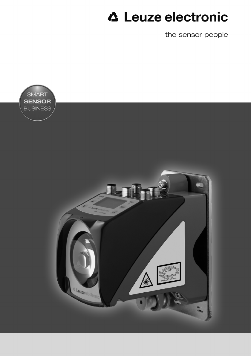
The main menus
Input of values
AMS 348i 120
Leuze electronic
GmbH & Co. KG
SW: V 1.3.0 HW:1
SN: -----------------------
Network information
Address: ---.---.---.--Net mask: ---.---.---.--Gateway: ---.---.---.--MAC ID: --.--.--.--.--.-DevName: ------------------------
IO1 LSR PLB LNK0
IO2 TMP ATT LNK1
ERR
+ 87.000m
Parameter
Parameter handling
PROFINET
Position value
I/O
Other
Device information - main menu
This menu item contains detailed information on
• Device model,
• Manufacturer,
• Software and hardware version,
• Serial number.
No entries can be made via the display.
Network information - main menu
Under this menu item, you will find detailed
information on the network addresses.
No entries can be made via the display.
Status- and measurement data main menu
• Display of status-, warning-, and error messages.
• Status overview of the switching inputs/outputs.
• Bar graph for the reception level.
• Activated interface.
• Measurement value.
No entries can be made via the display.
See "Indicators in the display" on page 38.
Parameter - main menu
Configuration for PROFI NET is carried out via the
modules of the GSDML file.
100
<-|0123456789 save
Standard ----- Unit
126 | |
Language selection
o Deutsch
English
o Español
o Français
o Italiano
Service
Status messages
Diagnostics
Expanded diagnostics
Language selection - main menu
• Selection of the display language.
See "Language selection menu" on page 48.
Service - main menu
• Display of status messages.
• Display of diagnostic data.
No entries can be made via the display.
See "Service menu" on page 48.
Page 4

Table of contents
1 General information . . . . . . . . . . . . . . . . . . . . . . . . . . . . . . . . . . . . 5
1.1 Explanation of symbols . . . . . . . . . . . . . . . . . . . . . . . . . . . . . . . . . . . . . . . . . . . . . . . . . . . 5
1.2 Declaration of conformity . . . . . . . . . . . . . . . . . . . . . . . . . . . . . . . . . . . . . . . . . . . . . . . . . 5
1.3 Description of functions AMS 348i . . . . . . . . . . . . . . . . . . . . . . . . . . . . . . . . . . . . . . . . . . 6
2 Safety . . . . . . . . . . . . . . . . . . . . . . . . . . . . . . . . . . . . . . . . . . . . . . . 7
2.1 Intended use . . . . . . . . . . . . . . . . . . . . . . . . . . . . . . . . . . . . . . . . . . . . . . . . . . . . . . . . . . . 7
2.2 Foreseeable misuse. . . . . . . . . . . . . . . . . . . . . . . . . . . . . . . . . . . . . . . . . . . . . . . . . . . . . . 8
2.3 Competent persons . . . . . . . . . . . . . . . . . . . . . . . . . . . . . . . . . . . . . . . . . . . . . . . . . . . . . . 8
2.4 Disclaimer. . . . . . . . . . . . . . . . . . . . . . . . . . . . . . . . . . . . . . . . . . . . . . . . . . . . . . . . . . . . . . 9
2.5 Laser safety notices. . . . . . . . . . . . . . . . . . . . . . . . . . . . . . . . . . . . . . . . . . . . . . . . . . . . . . 9
3 Fast commissioning / operating principle . . . . . . . . . . . . . . . . . . . 12
3.1 Mounting the AMS 348i . . . . . . . . . . . . . . . . . . . . . . . . . . . . . . . . . . . . . . . . . . . . . . . . . . 12
3.1.1 Mounting the device . . . . . . . . . . . . . . . . . . . . . . . . . . . . . . . . . . . . . . . . . . . . . . . . . . . . . 12
3.1.2 Mounting the reflector. . . . . . . . . . . . . . . . . . . . . . . . . . . . . . . . . . . . . . . . . . . . . . . . . . . . 12
3.2 Connecting the voltage supply . . . . . . . . . . . . . . . . . . . . . . . . . . . . . . . . . . . . . . . . . . . . 13
3.3 Display . . . . . . . . . . . . . . . . . . . . . . . . . . . . . . . . . . . . . . . . . . . . . . . . . . . . . . . . . . . . . . . 13
3.4 AMS 348i on the PROFINET . . . . . . . . . . . . . . . . . . . . . . . . . . . . . . . . . . . . . . . . . . . . . . 13
4 Specifications . . . . . . . . . . . . . . . . . . . . . . . . . . . . . . . . . . . . . . . . 14
4.1 Specifications of the laser measurement system . . . . . . . . . . . . . . . . . . . . . . . . . . . . . 14
4.1.1 General specifications AMS 348i . . . . . . . . . . . . . . . . . . . . . . . . . . . . . . . . . . . . . . . . . . . 14
4.1.2 Dimensioned drawing AMS 348i . . . . . . . . . . . . . . . . . . . . . . . . . . . . . . . . . . . . . . . . . . . 16
4.1.3 Type overview AMS 348i . . . . . . . . . . . . . . . . . . . . . . . . . . . . . . . . . . . . . . . . . . . . . . . . . 17
5 Installation and mounting . . . . . . . . . . . . . . . . . . . . . . . . . . . . . . . 18
5.1 Storage, transportation . . . . . . . . . . . . . . . . . . . . . . . . . . . . . . . . . . . . . . . . . . . . . . . . . . 18
5.2 Mounting the AMS 348i . . . . . . . . . . . . . . . . . . . . . . . . . . . . . . . . . . . . . . . . . . . . . . . . . . 19
5.2.1 Optional mounting bracket . . . . . . . . . . . . . . . . . . . . . . . . . . . . . . . . . . . . . . . . . . . . . . . . 21
5.2.2 Parallel mounting of the AMS 348i . . . . . . . . . . . . . . . . . . . . . . . . . . . . . . . . . . . . . . . . . . 22
5.2.3 Parallel mounting of AMS 348i and DDLS optical data transmission. . . . . . . . . . . . . . . . 23
5.3 Mounting the AMS 348i with laser beam deflector unit . . . . . . . . . . . . . . . . . . . . . . . . . 24
5.3.1 Mounting the laser beam deflector unit With integrated mounting bracket . . . . . . . . . . . 24
5.3.2 Dimensioned drawing of US AMS 01 deflector unit . . . . . . . . . . . . . . . . . . . . . . . . . . . . . 25
5.3.3 Mounting the US 1 OMS deflector unit without mounting bracket . . . . . . . . . . . . . . . . . 26
AMS 348i 1
Page 5

Table of contents
6 Reflectors . . . . . . . . . . . . . . . . . . . . . . . . . . . . . . . . . . . . . . . . . . . 27
6.1 General information . . . . . . . . . . . . . . . . . . . . . . . . . . . . . . . . . . . . . . . . . . . . . . . . . . . . .27
6.2 Description of the reflective tape. . . . . . . . . . . . . . . . . . . . . . . . . . . . . . . . . . . . . . . . . . . 27
6.2.1 Specifications of the self-adhesive foil . . . . . . . . . . . . . . . . . . . . . . . . . . . . . . . . . . . . . . . 28
6.2.2 Specifications of the reflective tape on a support plate . . . . . . . . . . . . . . . . . . . . . . . . . . 28
6.2.3 Dimensioned drawing of reflective tape on a support plate . . . . . . . . . . . . . . . . . . . . . . . 29
6.2.4 Specifications of heated reflectors . . . . . . . . . . . . . . . . . . . . . . . . . . . . . . . . . . . . . . . . . . 30
6.2.5 Dimensioned drawing of heated reflectors . . . . . . . . . . . . . . . . . . . . . . . . . . . . . . . . . . . . 31
6.3 Selecting reflector sizes . . . . . . . . . . . . . . . . . . . . . . . . . . . . . . . . . . . . . . . . . . . . . . . . . . 32
6.4 Mounting the reflector . . . . . . . . . . . . . . . . . . . . . . . . . . . . . . . . . . . . . . . . . . . . . . . . . . . 33
6.4.1 General information . . . . . . . . . . . . . . . . . . . . . . . . . . . . . . . . . . . . . . . . . . . . . . . . . . . . . . 33
6.4.2 Mounting the reflector . . . . . . . . . . . . . . . . . . . . . . . . . . . . . . . . . . . . . . . . . . . . . . . . . . . . 33
6.4.3 Table of reflector pitches . . . . . . . . . . . . . . . . . . . . . . . . . . . . . . . . . . . . . . . . . . . . . . . . . . 36
7 Electrical connection . . . . . . . . . . . . . . . . . . . . . . . . . . . . . . . . . . 37
7.1 Safety notices for the electrical connection . . . . . . . . . . . . . . . . . . . . . . . . . . . . . . . . . . 37
7.2 PWR – voltage supply / switching input/output . . . . . . . . . . . . . . . . . . . . . . . . . . . . . . . 38
7.3 PROFINET BUS IN . . . . . . . . . . . . . . . . . . . . . . . . . . . . . . . . . . . . . . . . . . . . . . . . . . . . . . 38
7.4 PROFINET BUS OUT . . . . . . . . . . . . . . . . . . . . . . . . . . . . . . . . . . . . . . . . . . . . . . . . . . . . 39
7.5 Service. . . . . . . . . . . . . . . . . . . . . . . . . . . . . . . . . . . . . . . . . . . . . . . . . . . . . . . . . . . . . . . .39
8 Display and control panel AMS 348i . . . . . . . . . . . . . . . . . . . . . . . 40
8.1 Structure of the control panel . . . . . . . . . . . . . . . . . . . . . . . . . . . . . . . . . . . . . . . . . . . . . 40
8.2 Status display and operation . . . . . . . . . . . . . . . . . . . . . . . . . . . . . . . . . . . . . . . . . . . . . . 40
8.2.1 Indicators in the display. . . . . . . . . . . . . . . . . . . . . . . . . . . . . . . . . . . . . . . . . . . . . . . . . . . 40
8.2.2 LED status displays . . . . . . . . . . . . . . . . . . . . . . . . . . . . . . . . . . . . . . . . . . . . . . . . . . . . . . 42
8.2.3 Control buttons . . . . . . . . . . . . . . . . . . . . . . . . . . . . . . . . . . . . . . . . . . . . . . . . . . . . . . . . . 44
8.3 Menu description . . . . . . . . . . . . . . . . . . . . . . . . . . . . . . . . . . . . . . . . . . . . . . . . . . . . . . .45
8.3.1 The main menus . . . . . . . . . . . . . . . . . . . . . . . . . . . . . . . . . . . . . . . . . . . . . . . . . . . . . . . . 45
8.3.2 Parameter menu . . . . . . . . . . . . . . . . . . . . . . . . . . . . . . . . . . . . . . . . . . . . . . . . . . . . . . . . 47
8.3.3 Language selection menu . . . . . . . . . . . . . . . . . . . . . . . . . . . . . . . . . . . . . . . . . . . . . . . . .50
8.3.4 Service menu . . . . . . . . . . . . . . . . . . . . . . . . . . . . . . . . . . . . . . . . . . . . . . . . . . . . . . . . . . . 50
8.4 Operation. . . . . . . . . . . . . . . . . . . . . . . . . . . . . . . . . . . . . . . . . . . . . . . . . . . . . . . . . . . . . . 51
9 PROFINET interface. . . . . . . . . . . . . . . . . . . . . . . . . . . . . . . . . . . . 53
9.1 General information on PROFINET . . . . . . . . . . . . . . . . . . . . . . . . . . . . . . . . . . . . . . . . . 53
9.2 Identification & Maintenance Functions . . . . . . . . . . . . . . . . . . . . . . . . . . . . . . . . . . . . . 53
2 AMS 348i
Page 6

Table of contents
9.3 PROFINET – star topology . . . . . . . . . . . . . . . . . . . . . . . . . . . . . . . . . . . . . . . . . . . . . . . 54
9.4 PROFINET – linear topology . . . . . . . . . . . . . . . . . . . . . . . . . . . . . . . . . . . . . . . . . . . . . . 54
9.5 PROFINET – General information on wiring . . . . . . . . . . . . . . . . . . . . . . . . . . . . . . . . . . 55
9.6 PROFINET – Cable lengths and shielding . . . . . . . . . . . . . . . . . . . . . . . . . . . . . . . . . . . 55
9.7 PROFINET - Electrical connection . . . . . . . . . . . . . . . . . . . . . . . . . . . . . . . . . . . . . . . . . 56
9.8 PROFINET – Commissioning and configuration. . . . . . . . . . . . . . . . . . . . . . . . . . . . . . . 57
9.8.1 PROFINET implementation of the AMS 348i . . . . . . . . . . . . . . . . . . . . . . . . . . . . . . . . . . 57
9.8.2 Measures to be performed prior to the initial commissioning . . . . . . . . . . . . . . . . . . . . . 58
9.8.3 Starting the device . . . . . . . . . . . . . . . . . . . . . . . . . . . . . . . . . . . . . . . . . . . . . . . . . . . . . . 59
9.8.4 Configuration steps for a Siemens Simatic S7 control . . . . . . . . . . . . . . . . . . . . . . . . . . . 60
9.9 PROFINET GSD file . . . . . . . . . . . . . . . . . . . . . . . . . . . . . . . . . . . . . . . . . . . . . . . . . . . . . 67
9.9.1 General information on the GSD file . . . . . . . . . . . . . . . . . . . . . . . . . . . . . . . . . . . . . . . . . 67
9.9.2 Overview of the GSD modules . . . . . . . . . . . . . . . . . . . . . . . . . . . . . . . . . . . . . . . . . . . . . 69
9.9.3 Detail description of the modules . . . . . . . . . . . . . . . . . . . . . . . . . . . . . . . . . . . . . . . . . . . 71
10 Diagnostics and troubleshooting . . . . . . . . . . . . . . . . . . . . . . . . . 96
10.1 Service and diagnostics in the display of the AMS 348i . . . . . . . . . . . . . . . . . . . . . . . . 97
10.1.1 Status messages . . . . . . . . . . . . . . . . . . . . . . . . . . . . . . . . . . . . . . . . . . . . . . . . . . . . . . . 97
10.1.2 Diagnostics . . . . . . . . . . . . . . . . . . . . . . . . . . . . . . . . . . . . . . . . . . . . . . . . . . . . . . . . . . . . 98
10.1.3 Expanded diagnostics . . . . . . . . . . . . . . . . . . . . . . . . . . . . . . . . . . . . . . . . . . . . . . . . . . . 98
10.2 General causes of errors . . . . . . . . . . . . . . . . . . . . . . . . . . . . . . . . . . . . . . . . . . . . . . . . . 98
10.2.1 Power LED . . . . . . . . . . . . . . . . . . . . . . . . . . . . . . . . . . . . . . . . . . . . . . . . . . . . . . . . . . . . 99
10.3 Interface errors. . . . . . . . . . . . . . . . . . . . . . . . . . . . . . . . . . . . . . . . . . . . . . . . . . . . . . . . . 99
10.3.1 BUS LED . . . . . . . . . . . . . . . . . . . . . . . . . . . . . . . . . . . . . . . . . . . . . . . . . . . . . . . . . . . . . . 99
10.4 Status display in the display of the AMS 348i . . . . . . . . . . . . . . . . . . . . . . . . . . . . . . . 100
11 Type overview and accessories . . . . . . . . . . . . . . . . . . . . . . . . . 102
11.1 Type key . . . . . . . . . . . . . . . . . . . . . . . . . . . . . . . . . . . . . . . . . . . . . . . . . . . . . . . . . . . . . 102
11.2 Type overview AMS 348i (PROFINET) . . . . . . . . . . . . . . . . . . . . . . . . . . . . . . . . . . . . . 102
11.3 Overview of reflector types . . . . . . . . . . . . . . . . . . . . . . . . . . . . . . . . . . . . . . . . . . . . . . 103
11.4 Accessories . . . . . . . . . . . . . . . . . . . . . . . . . . . . . . . . . . . . . . . . . . . . . . . . . . . . . . . . . . 103
11.4.1 Accessory mounting bracket . . . . . . . . . . . . . . . . . . . . . . . . . . . . . . . . . . . . . . . . . . . . . 103
11.4.2 Accessory deflector unit . . . . . . . . . . . . . . . . . . . . . . . . . . . . . . . . . . . . . . . . . . . . . . . . . 103
11.4.3 Accessory M12 connector . . . . . . . . . . . . . . . . . . . . . . . . . . . . . . . . . . . . . . . . . . . . . . . 103
11.4.4 Accessory ready-made cables for voltage supply . . . . . . . . . . . . . . . . . . . . . . . . . . . . . 104
11.4.5 Accessory ready-made cables for PROFINET . . . . . . . . . . . . . . . . . . . . . . . . . . . . . . . . 105
AMS 348i 3
Page 7

Table of contents
12 Maintenance . . . . . . . . . . . . . . . . . . . . . . . . . . . . . . . . . . . . . . . . 107
12.1 General maintenance information . . . . . . . . . . . . . . . . . . . . . . . . . . . . . . . . . . . . . . . . . 107
12.2 Repairs, servicing . . . . . . . . . . . . . . . . . . . . . . . . . . . . . . . . . . . . . . . . . . . . . . . . . . . . . . 107
12.3 Disassembling, packing, disposing . . . . . . . . . . . . . . . . . . . . . . . . . . . . . . . . . . . . . . . . 107
4 AMS 348i
Page 8

1 General information
U
L
US
C
LISTED
1.1 Explanation of symbols
The symbols used in this operating manual are explained below.
Attention!
This symbol precedes text messages which must strictly be observed. Failure to comply with
this information results in injuries to personnel or damage to the equipment.
Attention Laser!
This symbol warns of possible danger caused by hazardous laser radiation.
Notice!
This symbol indicates text passages containing important information.
1.2 Declaration of conformity
The AMS 348i absolute measuring optical laser measurement system was designed and
manufactured in accordance with applicable European directives and standards.
The AMS series is "UL LISTED" according to American and Canadian safety standards and
fulfills the requirements of Underwriter Laboratories Inc. (UL).
General information
Notice!
The Declaration of Conformity for these devices can be requested from the manufacturer.
The manufacturer of the product, Leuze electronic GmbH + Co. KG in D-73277 Owen,
possesses a certified quality assurance system in accordance with ISO 9001.
Leuze electronic AMS 348i 5
TNT 35/7-24V
Page 9

General information
1.3 Description of functions AMS 348i
The AMS 348i optical laser measurement system calculates distances to fixed as well as
moving system parts. The distance to be measured is calculated according to the principle
of the propagation time of radiated light. Here, the light emitted by the laser diode is reflected
by a reflector onto the receiving element of the laser measurement system. The AMS 348i
uses the "propagation time" of the light to calculate the distance to the reflector. The high
absolute measurement accuracy of the laser measurement system and the fast response
time are designed for position control applications.
With the AMS 3xxi product series, Leuze electronic makes available a range of internationally relevant interfaces. Note that each interface version listed below corresponds to a
different AMS 3xxi model.
AMS 304i
AMS 348i
AMS 355i
AMS 358i
AMS 335i
AMS 338i
AMS 308i
AMS 384i
AMS 301i
AMS 300i
6 AMS 348i Leuze electronic
Page 10
2 Safety
This sensor was developed, manufactured and tested in line with the applicable safety standards. It corresponds to the state of the art.
2.1 Intended use
The AMS is an absolute measuring optical laser measurement system which allows
distance measurement of up to 300m against a reflector.
Areas of application
The AMS is designed for the following areas of application:
• Positioning of automated, moving plant components
• Travel and lifting axes of high-bay storage devices
• Repositioning units
• Gantry crane bridges and their trolleys
•Lifts
• Electroplating plants
CAUTION
Observe intended use!
Only operate the device in accordance with its intended use. The protection of per-
sonnel and the device cannot be guaranteed if the device is operated in a manner not
complying with its intended use.
Leuze electronic GmbH + Co. KG is not liable for damages caused by improper use.
Read the technical description before commissioning the device. Knowledge of this
technical description is an element of proper use.
Safety
NOTICE
Comply with conditions and regulations!
Observe the locally applicable legal regulations and the rules of the employer's liability
insurance association.
Attention
For UL applications, use is permitted exclusively in Class 2 circuits according to NEC
(National Electric Code).
Leuze electronic AMS 348i 7
TNT 35/7-24V
Page 11

Safety
2.2 Foreseeable misuse
Any use other than that defined under "Intended use" or which goes beyond that use is
considered improper use.
In particular, use of the device is not permitted in the following cases:
• Rooms with explosive atmospheres
• As stand-alone safety component in accordance with the machinery directive
• For medicinal purposes
NOTICE
Do not modify or otherwise interfere with the device.
Do not carry out modifications or otherwise interfere with the device.
The device must not be tampered with and must not be changed in any way.
The device must not be opened. There are no user-serviceable parts inside.
Repairs must only be performed by Leuze electronic GmbH + Co. KG.
2.3 Competent persons
Connection, mounting, commissioning and adjustment of the device must only be carried
out by competent persons.
Prerequisites for competent persons:
• They have a suitable technical education.
• They are familiar with the rules and regulations for occupational safety and safety at
work.
• They are familiar with the technical description of the device.
• They have been instructed by the responsible person on the mounting and operation
of the device.
1)
Certified electricians
Electrical work must be carried out by a certified electrician.
Due to their technical training, knowledge and experience as well as their familiarity with
relevant standards and regulations, certified electricians are able to perform work on electrical systems and independently detect possible dangers.
In Germany, certified electricians must fulfill the requirements of accident-prevention regulations BGV A3 (e.g. electrician foreman). In other countries, there are respective regulations that must be observed.
1) Use as safety-related component within the safety function is possible, if the component combination is designed correspondingly by the machine manufacturer.
8 AMS 348i Leuze electronic
Page 12
2.4 Disclaimer
Leuze electronic GmbH + Co. KG is not liable in the following cases:
• The device is not being used properly.
• Reasonably foreseeable misuse is not taken into account.
• Mounting and electrical connection are not properly performed.
• Changes (e.g., constructional) are made to the device.
2.5 Laser safety notices
ATTENTION LASER RADIATION – LASER CLASS 2
Never look directly into the beam!
The device satisfies the requirements of IEC 60825-1:2007 (EN 60825-1:2007) safety
regulations for a product in laser class 2 as well as the U.S. 21 CFR 1040.10 regulations
with deviations corresponding to "Laser Notice No. 50" from June 24th, 2007.
Never look directly into the laser beam or in the direction of reflecting laser beams.
If you look into the beam path over a longer time period, there is a risk of injury to the
retina.
Do not point the laser beam of the device at persons!
Interrupt the laser beam using a non-transparent, non-reflective object if the laser
beam is accidentally directed towards a person.
When mounting and aligning the device, avoid reflections of the laser beam off reflec-
tive surfaces!
CAUTION! The use of operating or adjusting devices other than those specified here
or carrying out of differing procedures may lead to dangerous exposure to radiation.
Adhere to the applicable legal and local regulations regarding protection from laser
beams.
The device must not be tampered with and must not be changed in any way.
There are no user-serviceable parts inside the device.
Repairs must only be performed by Leuze electronic GmbH + Co. KG.
Safety
TNT 35/7-24V
Leuze electronic AMS 348i 9
Page 13
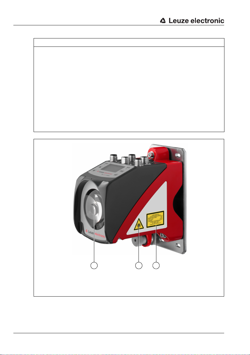
Safety
A Laser aperture
B Laser warning sign
C Laser information sign with laser parameters
A B
C
NOTICE
Affix laser information and warning signs!
Laser information and warning signs are attached to the device (see figure 2.1):
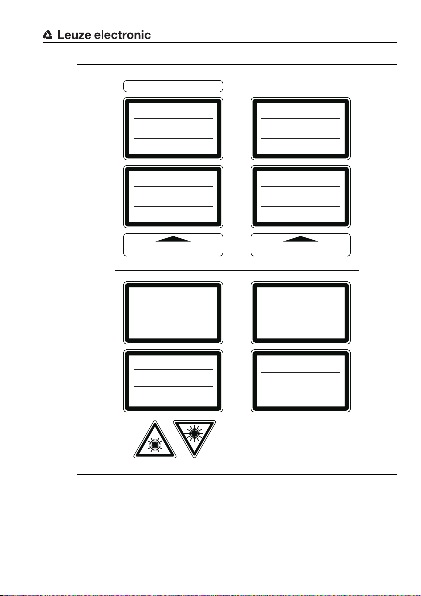
In addition, self-adhesive laser warning and information signs (stick-on labels) are supplied
in several languages (see figure 2.2).
Affix the laser information sheet to the device in the language appropriate for the place
of use.
When using the device in the US, use the stick-on label with the "Complies with
21 CFR 1040.10" notice.
Affix the laser information and warning signs near the device if no signs are attached
to the device (e.g., because the device is too small) or if the attached laser information
and warning signs are concealed due to the installation position.
Affix the laser information and warning signs so that they are legible without exposing
the reader to the laser radiation of the device or other optical radiation.
Figure 2.1: Laser apertures, laser warning signs
10 AMS 348i Leuze electronic
Page 14
AVOID EXPOSURE – LASER RADIATION
IS EMITTED FROM THIS APERTURE
EXPOSITION DANGEREUSE – UN RAYONNEMENT
LASER EST ÉMIS PAR CETTE OUVERTURE
LASERSTRAHLUNG
NICHT IN DEN STRAHL BLICKEN
LASER KLASSE 2
DIN EN 60825-1:2008-05
Max. Leistung (peak):
Impulsdauer:
Wellenlänge:
RADIAZIONE LASER
NON FISSARE IL FASCIO
APARRECCHIO LASER DI CLASSE 2
EN 60825-1:2007
Potenza max. (peak):
Durata dell'impulso:
Lunghezza d'onda:
LASER RADIATION
DO NOT STARE INTO BEAM
CLASS 2 LASER PRODUCT
EN 60825-1:2007
Maximum Output (peak):
Pulse duration:
Wavelength:
RAYONNEMENT LASER
NE PAS REGARDER DANS LE FAISCEAU
APPAREIL À LASER DE CLASSE 2
EN 60825-1:2007
Puissance max. (crête):
Durée d`impulsion:
Longueur d`onde:
RADIACIÓN LÁSER
NO MIRAR FIJAMENTE AL HAZ
PRODUCTO LÁSER DE CLASE 2
EN 60825-1:2007
Potencia máx. (peak):
Duración del impulso:
Longitud de onda:
RADIAÇÃO LASER
NÃO OLHAR FIXAMENTE O FEIXE
EQUIPAMENTO LASER CLASSE 2
EN 60825-1:2007
Potência máx. (peak):
Período de pulso:
Comprimento de onda:
LASER RADIATION
DO NOT STARE INTO BEAM
CLASS 2 LASER PRODUCT
IEC 60825-1:2007
Complies with 21 CFR 1040.10
Maximum Output (peak):
Pulse duration:
Wavelength:
䉏⏘戟⺓
▎䦃展⏘㧮
伊䉏⏘ℶ❐
GB7247.1-2012
㦏⮶戢⒉᧤⽿⋋᧥
厘⑁㖐兼㢅梃
㽱栎
4 mW
18 μs
655 nm
4 mW
18 μs
655 nm
4 mW
18 μs
655 nm
4 mW
18
μ
s
655 nm
4 mW
18 μs
655 nm
4 mW
18 μs
655 nm
4 mW
18 μs
655 nm
4 mW
18 μs
655 nm
50125612-01
Safety
Figure 2.2: Laser warning and information signs – supplied stick-on labels
TNT 35/7-24V
Leuze electronic AMS 348i 11
Page 15
Fast commissioning / operating principle
3 Fast commissioning / operating principle
Notice!
Below, you will find a short description for the initial commissioning of the AMS 348i.
Detailed explanations for the listed points can be found throughout the handbook.
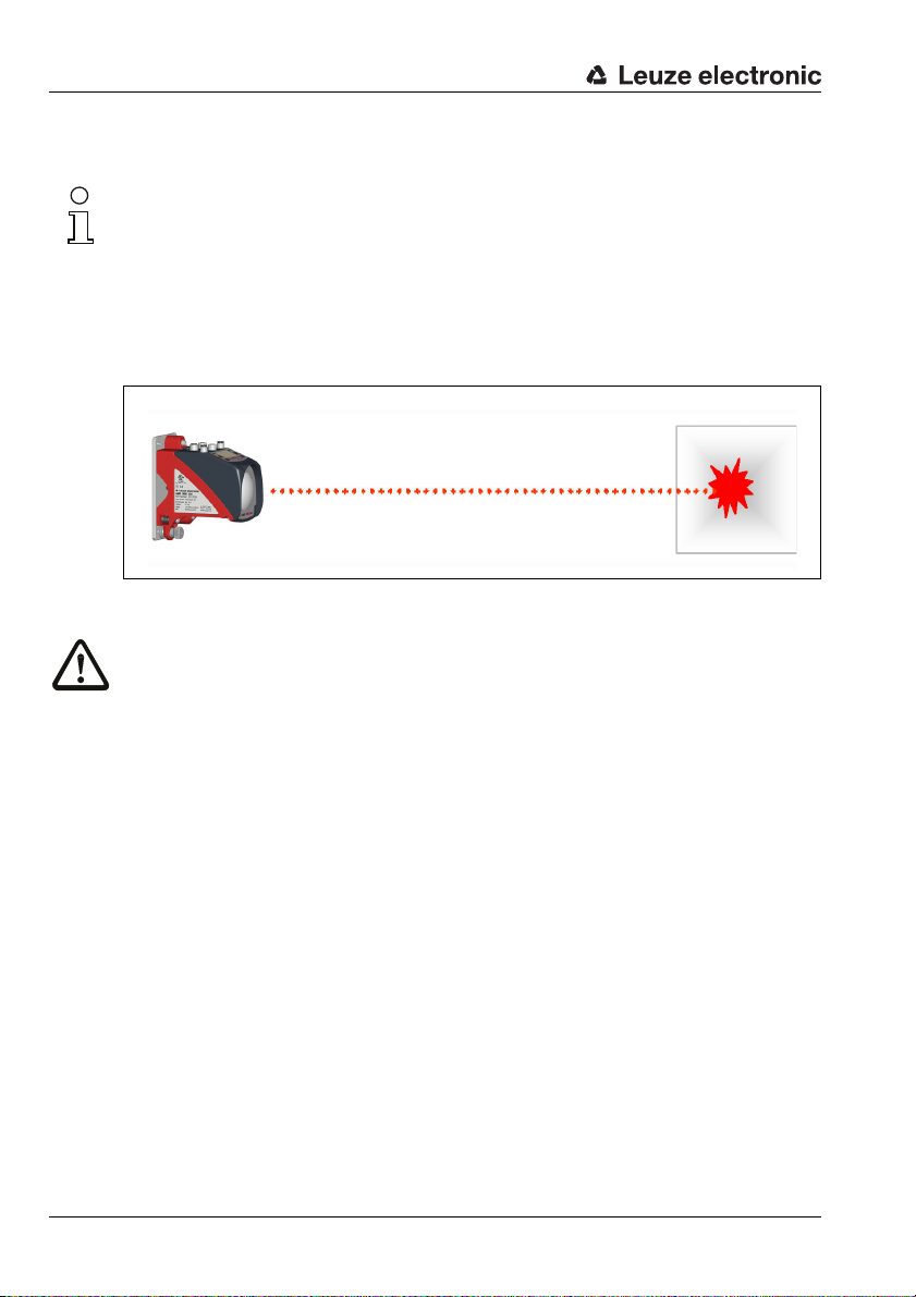
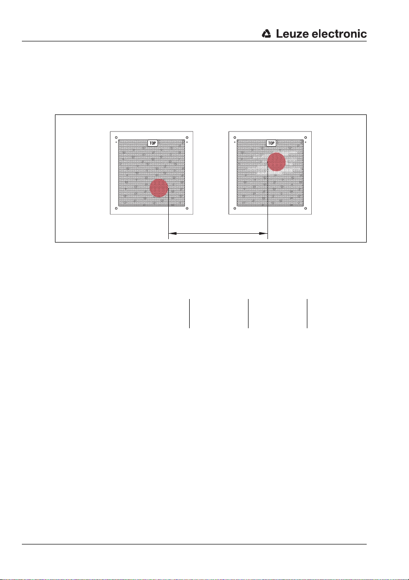
3.1 Mounting the AMS 348i
The AMS 348i and the corresponding reflector are mounted on two mutually opposing,
plane-parallel, flat walls.
Figure 3.1: Schematic illustration of mounting
Attention!
For error-free position measurement, there must be an unobstructed line-of-sight between
the AMS 348i and the reflector.
3.1.1 Mounting the device
The laser is mounted on a vertical wall using 4 screws (M5).
Alignment is performed using 2 adjustment screws. Adjust so that the laser light spot is
positioned at the center of the reflector. The alignment is to be secured with the knurled nut
and locked with the M5 nut.
Further information can be found in chapter 5.2 and chapter 5.3.
3.1.2 Mounting the reflector
The reflector is mounted on a vertical wall with 4 screws (M5). The reflector is angled using
the included shims. Incline the reflector by approx. 1°.
Detailed information can be found in chapter 6.4.
12 AMS 348i Leuze electronic
Page 16

Fast commissioning / operating principle
3.2 Connecting the voltage supply
The laser measurement system is connected using M12 connectors. The voltage supply is
connected via the PWR M12 connection (18 … 30 VDC). 2 freely programmable switching
inputs/outputs for individual adaptation to the respective application are also available here.
Detailed information can be found in chapter 7.
3.3 Display
Once the laser measurement system is supplied with voltage, the device status as well as
the measured position values can be read on the display. The display automatically switches
to the display of the measurement values.
Use the up/down buttons to the left of the display to read and change a wide range
of data and parameters.
Detailed information can be found in chapter 8.
3.4 AMS 348i on the PROFINET
Install the GSDML file associated with the AMS 348i in the PROFINET Manager of your
control. Activate the desired modules (at least one module).
The network address for PROFINET is assigned via the PROFINET Manager.
Standalone operation in PROFINET
During standalone operation of the AMS 348i, the PROFINET network is connected to
BUS IN. BUS OUT requires no terminating resistor.
Network operation in PROFINET
In network mode the AMS 348i is connected to PROFINET via BUS IN. Further PROFINET
participants can be connected to the integrated switch of the AMS 348i via the BUS OUT
connection.
Commissioning of the AMS 348i
The procedures described below are for the configuration of an AMS 348i with a Siemens
Simatic S7 PLC.
• Switching on the supply voltage.
The AMS 348i displays the "Status and measurement values" main menu.
• Installation of the corresponding GSD file in the Simatic Hardware Manager.
• Projection of the PROFINET network including the AMS 348i GSD file. Definition of
the IP addresses, sub-network mask and definition of a device name assigned to the
IP address.
• Download of the project to the connected Siemens control.
Further information regarding the individual commissioning steps is provided in see chapter
9.8.4 "Configuration steps for a Siemens Simatic S7 control".
Detailed information can be found in chapter 9.
Leuze electronic AMS 348i 13
TNT 35/7-24V
Page 17

Specifications
4 Specifications
4.1 Specifications of the laser measurement system
4.1.1 General specifications AMS 348i
Measurement data AMS 348i 40 (H) AMS 348i 120 (H) AMS 348i 200 (H) AMS 348i 300 (H)
Measurement range 0.2 … 40m 0.2 … 120m 0.2 … 200m 0.2 … 300m
Accuracy ± 2mm ± 2mm ± 3mm ± 5mm
Consistency
Light spot diameter ≤ 40mm ≤ 100mm ≤ 150mm ≤ 225mm
Output time
Response time 14ms
Basis for contouring error calculation 7ms
Resolution adjustable, see chapter of the individual interfaces
Temperature drift ≤ 0.1 mm/K
Ambient temperature sensitivity 1ppm/K
Air pressure sensitivity 0.3ppm/hPa
Tra ve rs e r at e ≤ 10 m/s
Electrical data
Supply voltage Vin
Current consumption without device heating: ≤ 250 mA / 24V DC
Optical data
Transmitter laser diode, red light
Laser class 2 acc. to IEC 60825-1:2007, CDRH
Wavelength 655nm
Impulse duration ≤ 18 μs
Max. output power (peak) ≤ 4mW
Interfaces
Interface type PROFINET-RT with integrated switch
Protocol PROFINET-RT communication
Conformance Class B
Operating and display elements
Keyboard 4 buttons
Display monochromatic graphical display, 128 x 64 pixels
LED 4 LEDs, 2 of which are used to display the PROFINET connection
1)
2)
0.3mm 0.5mm 0.7mm 1.0mm
1.7ms
18 … 30V DC
with device heating: ≤ 500 mA / 24VDC
for BUS IN and BUS OUT
14 AMS 348i Leuze electronic
Page 18

Specifications
Inputs/outputs
Quantity
Input
Output
Mechanical data
Housing cast zinc and aluminum
Optics glass
Weight approx. 2.45kg
Protection class
Environmental conditions
Operating temperature
without device heating
with device heating
Storage temperature -30°C … +70°C
Air humidity max. 90% rel. humidity, non-condensing
Mechanical/electrical loading capacity
Vibrations acc. to EN 60068-2-6
Noise acc. to EN 60060-2-64
Shock acc. to EN 60068-2-27
EMC
1) Statistical error: 1 sigma; minimum switch-on time: 2min.
2) For UL applications: only for use in "Class 2" circuits acc. to NEC.
3) With screwed-on M 12 plugs or mounted caps.
4) With devices with heating, the switch on/off area of the internal heating can be extended to prevent
condensation from forming. A 100% prevention of the formation of condensation cannot be guaranteed due to the limited heating capacity of the AMS 348i.
5) This is a Class A product. In a domestic environment this product may cause radio interference, in
which case the operator may be required to take adequate measures.
acc. to EN 61000-6-2 and EN 61000-6-4
2, programmable
protected against polarity reversal
max. 60mA, short-circuit proof
IP 65 acc. to EN 60529
3)
-5°C … +50°C
-30°C…+50°C
4)
5)
The AMS 348i is designed in accordance with safety class III for supply with
PELV (protective extra-low voltage).
Leuze electronic AMS 348i 15
TNT 35/7-24V
Page 19
Specifications
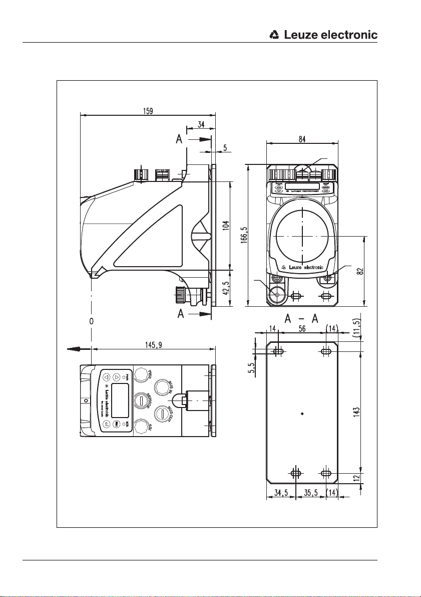
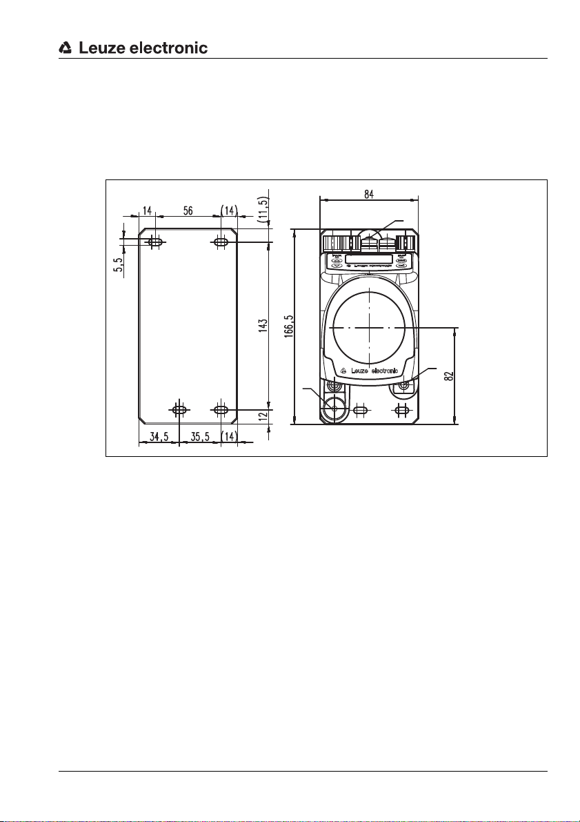
A M5 screw for alignment
B Knurled nut with WAF4
hexagon socket and M5 nut for securing
C Optical axis
D Zero point of the distance to be measured
A
B
D
A
C
4.1.2 Dimensioned drawing AMS 348i
16 AMS 348i Leuze electronic
Figure 4.1: Dimensioned drawing AMS 348i
Page 20

4.1.3 Type overview AMS 348i
AMS 348i (PROFINET)
Type designation Description Part no.
AMS 348i 40 40m operating range, PROFINET interface 50113709
AMS 348i 120 120m operating range, PROFINET interface 50113710
AMS 348i 200 200m operating range, PROFINET interface 50113711
AMS 348i 300 300m operating range, PROFINET interface 50113712
AMS 348i 40 H 40m operating range, PROFINET interface, integrated heating 50113713
AMS 348i 120 H 120m operating range, PROFINET interface, integrated heating 50113714
AMS 348i 200 H 200m operating range, PROFINET interface, integrated heating 50113715
AMS 348i 300 H 300m operating range, PROFINET interface, integrated heating 50113716
Table 4.1: Type overview AMS 348i
Specifications
Leuze electronic AMS 348i 17
TNT 35/7-24V
Page 21
Installation and mounting
5 Installation and mounting
5.1 Storage, transportation
Attention!
When transporting or storing, package the device so that it i s prote cted against collision and
humidity. Optimum protection is achieved when using the original packaging. Heed the required environmental conditions specified in the technical data.
Unpacking
Check the packaging for any damage. If damage is found, notify the post office or shipping
agent as well as the supplier.
Check the delivery contents using your order and the delivery papers:
• Delivered quantity
• Device type and model as indicated on the nameplate
• Brief manual
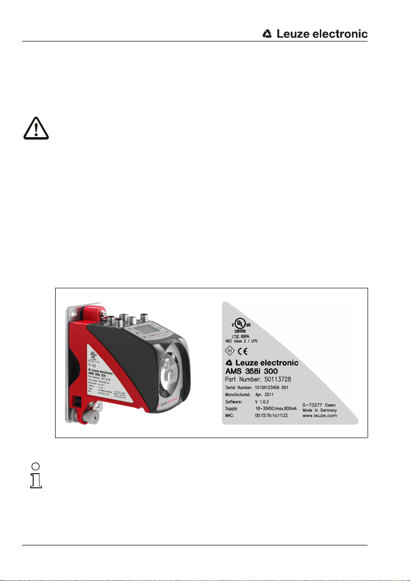
The name plate provides information as to what AMS 348i type your device is. For specific
information, please refer to chapter 11.2.
Name plates
Figure 5.1: Device name plate using the AMS 300i as an example
Notice!
Please note that the shown name plate is for illustration purposes only; the contents do not
correspond to the original.
Save the original packaging for later storage or shipping.
18 AMS 348i Leuze electronic
Page 22
If you have any questions concerning your shipment, please contact your supplier or your
A M5 screw for align-
ment
B Knurled nut and nut
with WAF4 hexagon
socket for securing
C Optical axis
A
B
A
C
local Leuze electronic sales office.
Observe the applicable local regulations when disposing of the packaging materials.
5.2 Mounting the AMS 348i
Installation and mounting
Figure 5.2: Mounting the device
The AMS 348i and the corresponding reflector are mounted on two mutually opposing,
plane-parallel, flat walls or system parts. For error-free position measurement, there must
be an unobstructed line-of-sight connection between the AMS 348i and the reflector.
Use M5 screws to fasten the laser measurement system. Secure the screws with a toothed
lock washer to protect against loosening caused by vibrations.
Leuze electronic AMS 348i 19
TNT 35/7-24V
Page 23
Installation and mounting
Aligning the laser light spot in the center of the reflector
The laser light spot has to be aligned so that it always hits the center of the opposing
reflector, both at close range as well as at the maximum measurement distance. To align,
use the two M5 Allen screws ("A" in figure 5.2). When aligning please ensure that the
knurled nut and the lock nut ("B" in figure 5.2) are opened wide.
Attention!
To prevent the laser measurement system from moving out of alignment during continuous
operation, subsequently hand-tighten the knurled nut and counterlock with the nut with
WAF4 hexagon socket ("B" in figure 5.2). Knurled nut and nut must not be tightened until
alignment has been completed.
Attention!
The device must not be opened. Failure to comply will render the guarantee void. Warranted
features cannot be guaranteed after the device has been opened.
20 AMS 348i Leuze electronic
Page 24
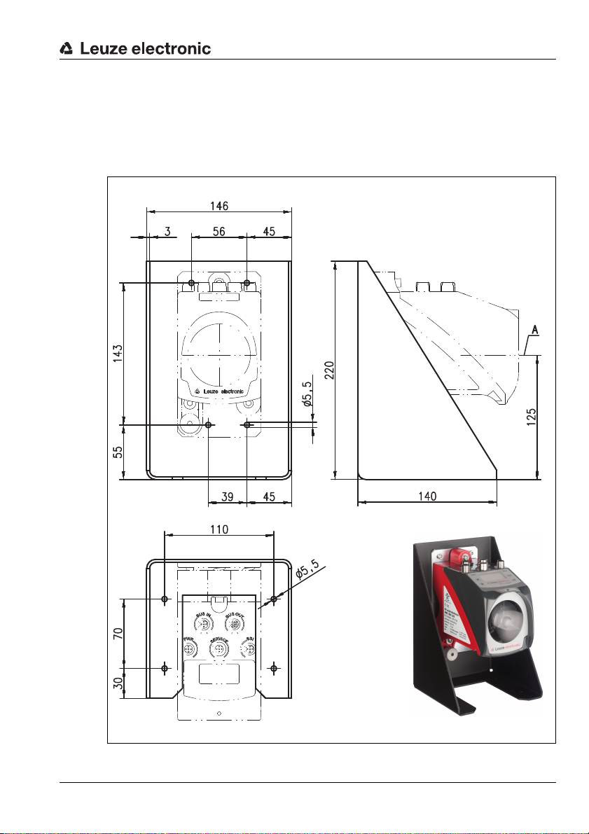
5.2.1 Optional mounting bracket
A Laser beam
A mounting bracket for mounting the AMS 348i on a flat, horizontal surface is available as
an optional accessory.
Type designation: MW OMS/AMS 01
Part no.: 50107255
Installation and mounting
Leuze electronic AMS 348i 21
TNT 35/7-24V
Figure 5.3: Optional mounting bracket
Page 25
Installation and mounting
X
Reflector 1 Reflector 2
5.2.2 Parallel mounting of the AMS 348i
Definition of the term "parallel spacing"
As shown in figure 5.4, dimension X describes the "parallel spacing" of the inner edges of
the two laser light spots on the reflector.
Figure 5.4: Minimum parallel spacing X between adjacent AMS 348i
The diameter of the light spot increases with distance.
AMS 348i 40 (H) AMS 348i 120 (H) AMS 348i 200 (H) AMS 348i 300 (H)
Max. measurement distance
Light spot diameter ≤ 40mm ≤ 100mm ≤ 150mm ≤ 225 mm
Thus, the center-to-center spacing of the two AMS 348i devices with respect to one another
can be calculated as a function of the maximum measurement distance.
To define the minimum parallel spacing between two AMS 348i, it is necessary to distinguish
between three different arrangements of AMS 348i and reflectors.
40m 120m 200m 300m
The AMS 348i are mounted stationary and in parallel on one plane. Both reflectors move independently of one another at different distances to the AMS 348i.
Minimum parallel spacing X of the two laser light spots:
X = 100mm + (max. measurement distance in mm x 0.01)
The AMS 348i are mounted stationary and in parallel on one plane. Both reflectors move in parallel at the same distance to the AMS 348i.
Measurement distance up to 120m: minimum parallel spacing X ≥ 600mm
Measurement distance up to 200m: minimum parallel spacing X ≥ 750mm
Measurement distance up to 300m: minimum parallel spacing X ≥ 750mm
22 AMS 348i Leuze electronic
Page 26

Installation and mounting
The reflectors are mounted stationary and in parallel on one plane.
Both AMS 348i move independently of one another at different or the same distances to the reflectors.
Measurement distance up to 120 m: minimum parallel spacing X ≥ 600 mm
Measurement distance up to 200 m: minimum parallel spacing X ≥ 750 mm
Measurement distance up to 300 m: minimum parallel spacing X ≥ 750 mm
Notice!
Please note that when the AMS 348i are mounted in a mobile manner, travel tolerances could
cause the two laser light spots to move towards each other.
Take the travel tolerances of the vehicle into account when defining the parallel spacing of
adjacent AMS 348i.
5.2.3 Parallel mounting of AMS 348i and DDLS optical data transmission
The optical data transceivers of the DDLS series and the AMS 348i do not interfere with one
another. Depending on the size of the used reflector, the DDLS can be mounted with a
minimum parallel spacing of 100mm to the AMS 348i. The parallel spacing is independent
of the distance.
Leuze electronic AMS 348i 23
TNT 35/7-24V
Page 27
Installation and mounting
5.3 Mounting the AMS 348i with laser beam deflector unit
General information
The two available deflector units are used for the 90° deflection of the laser beam,
see "Accessory deflector unit" on page 103.
Attention!
The deflector units are designed for a maximum range of 40m.
Longer distances on request.
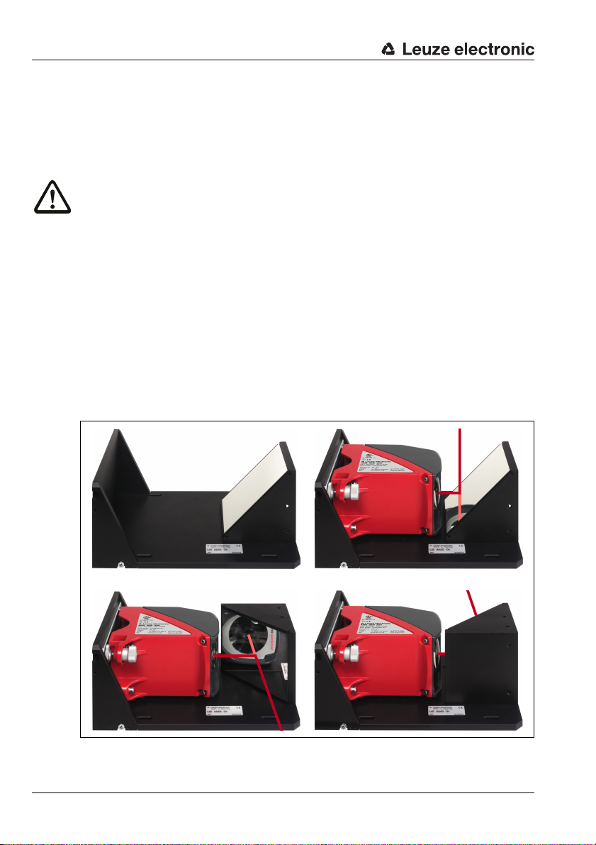
5.3.1 Mounting the laser beam deflector unit With integrated mounting bracket
The AMS 348i is screwed onto the mechanism of the US AMS 01 deflector unit. The mirror
can be mounted for three deflection directions:
1. Upward beam deflection
2. Beam deflection to the left
3. Beam deflection to the right
The deflector unit is mounted on plane-parallel, flat walls or plant components. For errorfree position measurement, there must be an interruption-free line-of-sight between the
AMS 348i… and the deflection mirror as well as between the mirror and the reflector.
Use the M5 screws to mount the deflector unit. Secure the screws with a toothed lock
washer to protect against loosening caused by vibrations.
Figure 5.5: Mounting variants of the US AMS 01 laser beam deflector unit
24 AMS 348i Leuze electronic
Page 28
Installation and mounting
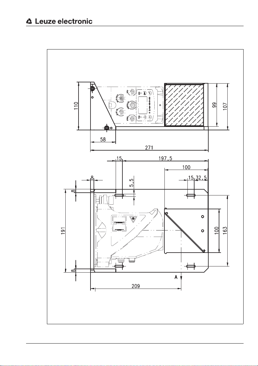
A Laser beam
5.3.2 Dimensioned drawing of US AMS 01 deflector unit
Leuze electronic AMS 348i 25
TNT 35/7-24V
Figure 5.6: Dimensioned drawing of US AMS 01 deflector unit
Page 29
Installation and mounting
A Mirror
Height of the spring in
non-preloaded state
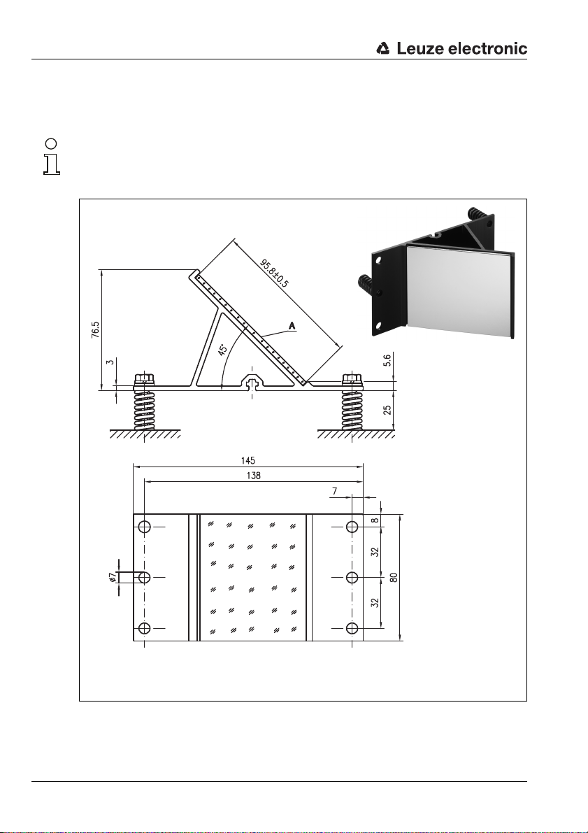
5.3.3 Mounting the US 1 OMS deflector unit without mounting bracket
The US 1 OMS deflector unit and the AMS 348i are mounted separately.
Notice!
When mounting, make certain that the laser light spot of the AMS 348i is aligned in the center
of the deflection mirror.
Figure 5.7: Photo and dimensioned drawing of the US 1 OMS deflector unit
Alignment of the laser light spot on the reflector is performed as described in chapter 5.2.
26 AMS 348i Leuze electronic
Page 30

6 Reflectors
6.1 General information
The AMS 348i measures distances against a reflective tape specified by Leuze electronic.
All provided specifications for the AMS 348i, such as the operating range or accuracy, can
only be achieved with the reflective tape specified by Leuze electronic.
The reflective tapes are available as adhesive tapes, affixed to a metal plate and with an
integrated heater especially for use at low temperatures. Reflective tapes with heating have
the designation "Reflective tape …x…-H", where "H" is an abbreviation for the heating
variant.
The reflective tapes/reflectors must be ordered separately. The choice of size is left to the
user. In chapter 6.3, recommendations on reflector size are provided as a function of the
distance that is to be measured. In any case, the user must check to determine whether the
recommendation is suitable for the respective application.
6.2 Description of the reflective tape
The reflective tape consists of a white, microprism-based reflective material. The microprisms are protected with a highly transparent, hard protective layer.
Under certain circumstances, the protective layer may lead to surface reflections. The
surface reflections can be directed past the AMS 348i by positioning the reflective tape at
a slight incline. The inclination of the reflective tape/reflectors is described in chapter 6.4.2.
The required pitch can be found in table 6.1 "Reflector pitch resulting from spacer sleeves"
on page 36.
The reflective tapes are provided with a protective fo il that ca n ea si ly be pulled of f. This mu st
be removed from the reflector before the complete system is put into operation.
Reflectors
Leuze electronic AMS 348i 27
TNT 35/7-24V
Page 31

Reflectors
6.2.1 Specifications of the self-adhesive foil
Part
Type designation
Part no. 50104361 50104362 50108988
Foil size 200x 200mm 500 x500 mm 914 x914 mm
Recommended application temperature for adhesive tape
Temperature resistance,
affixed
Mounting surface The mounting surface must be clean, dry and free of grease.
Cutting the tape Cut with a sharp tool, always on the side of the prism structure.
Cleaning
Storing the foil Store in a cool and dry place.
Reflective tape
200x200-S
Do not use any agents that act with a grinding effect. A conventional household
detergent can be used as a cleaning agent. Rinse with clear water and dry the
6.2.2 Specifications of the reflective tape on a support plate
The reflective tape is affixed to a support plate. Included with the support plate are spacers
for positioning at an incline - for avoiding surface reflections - (see chapter 6.4.2 "Mounting
the reflector").
Reflective tape
500x500-S
+5°C … +25 °C
-40°C…+80°C
surface.
Reflective tape
914x914-S
Part
Type designation
Part no. 50104364 50104365 50104366
Foil size 200x 200mm 500 x500 mm 914 x914 mm
Outer dimensions of the
support plate
Weight 1.2kg 2.8kg 25kg
Cleaning
Storing the reflector Store in a cool and dry place.
28 AMS 348i Leuze electronic
Reflective tape
200x200-M
250x 250mm 550 x550 mm 964x964 mm
Do not use any agents that act with a grinding effect. A conventional household
detergent can be used as a cleaning agent. Rinse with clear water and dry the
Reflective tape
500x500-M
surface.
Reflective tape
914x914-M
Page 32

6.2.3 Dimensioned drawing of reflective tape on a support plate
Always align the TOP marking
with the AMS connections!
(chapter 6.4.2)
Figure 6.1: Dimensioned drawing of reflectors
Part Reflective tape (mm) Reflector plate (mm)
xL yL XL YL L
Reflective tape 200x200-M 200 200 250 250 214
Reflective tape 500x500-M 500 500 550 550 514
Reflective tape 914x914-M 914 914 964 964 928
Reflectors
Leuze electronic AMS 348i 29
TNT 35/7-24V
Page 33

Reflectors
6.2.4 Specifications of heated reflectors
The reflective tape is affixed to a heated, thermally insulated base. The insulation results in
a very high energetic efficiency.
Only the reflective tape is kept at the specified temperature by the integrated heater.
Through the insulation on the back, the generated heat cannot be transferred via the steel
construction. Energy costs are greatly reduced in the case of continuous heating.
Type designation
Part no. 50115020 50115021 50115022
Voltage supply 230VAC
Power 100W 600W 1800 W
Current consumption ~ 0.5A ~ 3A ~ 8 A
Length of the supply line 2 m
Size of the reflective tape 200 x200 mm 500 x500 mm 914x914mm
Outer dimensions of the base
material
Weight 0.5kg 2.5 kg 12 kg
Temperature control
Switch-on temperature ~ 5°C
Switch-off temperature ~ 20°C
Operating temperature -30°C … +70°C
Storage temperature -40°C … +80°C
Air humidity Max. 90%, non-condensing.
Cleaning
Storing the reflector Store in a cool and dry place.
Reflective tape
200x200-H
250x 250mm 550x 550mm 964x 964mm
Controlled heating with the following switch-on and switch-off tempera-
Do not use any agents that act with a grinding effect. A conventional household detergent can be used as a cleaning agent. Rinse with clear water and
Part
Reflective tape
500x500-H
tures, measured at the reflector surface.
dry the surface.
Reflective tape
914x914-H
30 AMS 348i Leuze electronic
Page 34

6.2.5 Dimensioned drawing of heated reflectors
18
6,5
2
L ± 0,5
XL ± 1
TOP
6
2000
115
90
XL ± 1
yL ± 1
L ± 0,5
YL ± 1
Always align the TOP marking
with the AMS connections!
(chapter 6.4.2)
Connection hood
Reflective tape
Si cable
3 x 0.75mm²
Reflectors
Figure 6.2: Dimensioned drawing of heated reflectors
Part Reflective tape (mm) Insulated base plate (mm)
Reflective tape 200x200-H 200 200 250 250 214
xL yL XL YL L
Reflective tape 500x500-H 500 500 550 550 514
Reflective tape 914x914-H 914 914 964 964 928
Leuze electronic AMS 348i 31
TNT 35/7-24V
Page 35

Reflectors
6.3 Selecting reflector sizes
Depending on system design, the reflector can be mounted so that it travels on the vehicle
or it can be mounted at a fixed location.
Attention!
The reflector sizes shown below are a recommendation from Leuze electronic for on-vehicle
mounting of the AMS 348i. For stationary mounting of the AMS 348i, a smaller reflector is
generally sufficient for all measurement distances.
On the basis of the system planning and design, always check whether mechanical travel
tolerances may require the use of a reflector larger than that which is recommended. This
applies, in particular, when the laser measurement system is mounted on a vehicle. During
travel, the laser beam must reach the reflector without interruption. For on-vehicle mounting
of the AMS 348i, the reflector size must accommodate any travel tolerances that may arise
and the associated "wandering" of the light spot on the reflector.
Overview of reflector types
AMS 348i selection
(Operating range in m)
AMS 348i 40 (max. 40m) 200x200mm Reflective tape 200x200-S
AMS 348i 120 (max. 120m) 500x500mm Reflective tape 500x500-S
AMS 348i 200 (max. 200m) 749x 914mm
AMS 348i 300 (max. 300m) 749x 914mm
Recommended reflector sizes
Recommended
reflector size
(H x W)
914x 914mm
914x 914mm
Type designation
…-S = Self-adhesive
…-M = metal plate
…-H = heating
Reflective tape 200x200-M
Reflective tape 200x200-H
Reflective tape 500x500-M
Reflective tape 500x500-H
Reflective tape 749x914-S
Reflective tape 914x914-M
Reflective tape 914x914-S
Reflective tape 914x914-H
Reflective tape 749x914-S
Reflective tape 914x914-M
Reflective tape 914x914-S
Reflective tape 914x914-H
Part no.
50104361
50104364
50115020
50104362
50104365
50115021
50104363
50104366
50108988
50115022
50104363
50104366
50108988
50115022
32 AMS 348i Leuze electronic
Page 36

6.4 Mounting the reflector
6.4.1 General information
Self-adhesive reflective tapes
The reflective tapes of the "Reflective tape …x…-S" self-adhesive series must be affixed
to a flat, clean and grease-free surface. We recommend using a separate metal plate, which
is to be provided on-site.
As described in table 6.1, the reflective tape must be angled.
Reflective tapes on support plate
The reflective tapes of the "Reflective tape …x…-M" series are provided with corresponding
mounting holes. Spacer sleeves are provided in the packet for achieving the necessary pitch
angle. For further information see table 6.1.
Heated reflectors
The reflective tapes of the "Reflective tape ...x...-H" series are provided with corresponding
mounting holes. Due to the voltage supply affixed on the rear, the reflector cannot be
mounted flat. Included in the package are four distance sleeves in two different lengths. Use
the distance sleeves to achieve a base separation to the wall as well as the necessary pitch
for avoiding surface reflection. For further information see table 6.1.
The reflector is provided with a 2m-long connection cable for supplying with 230V AC.
Connect the cable to the closest power outlet. Observe the current consumptions listed in
the specifications.
Reflectors
Attention!
Connection work must be carried out by a certified electrician.
6.4.2 Mounting the reflector
The combination of laser measurement system and reflective tape/reflector is mounted so
that the laser light spot hits the tape as centered as possible and without interruption.
For this purpose, use the alignment elements provided on the AMS 348i… (see chapter 5.2
"Mounting the AMS 348i"). If necessary, remove the protective foil from the reflector.
Attention!
The "TOP" label mounted on the reflectors should be aligned the same as the connections
of the AMS 348i.
Example:
If the AMS 348i is mounted so that the M12 connections are on the top, the "TOP" label of
the reflector is also on the top. If the AMS 348i is mounted so that the M12 connections are
on the side, the "TOP" label of the reflector is also on the side.
Leuze electronic AMS 348i 33
TNT 35/7-24V
Page 37

Reflectors
Pitch approx. 1°
Direct reflection from the
triad structure
Deflected surface reflection due to
the pitch of the reflective tape
Pitch approx. 1°
Spacer sleeves
Notice!
The reflector must be angled. To do this, use the spacer sleeves. Angle the reflectors so that
the surface reflections of the foil seal are deflected to the left, right, upwards or down-
wards, chapter 6.4.3 gives the correct pitch with respect to the reflector size and, thus, the
length of the spacers.
Reflective tapes …-S and …-M
Figure 6.3: Reflector mounting
Figure 6.4: Pitch of the reflector
34 AMS 348i Leuze electronic
Page 38

Reflective tapes …-H
Pitch approx. 1°
Deflected surface reflection due to
the pitch of the reflective tape
Direct reflection from the
triad structure
Pitch approx. 1°
Spacer sleeves
Figure 6.5: Mounting of heated reflectors
Reflectors
Figure 6.6: Pitch of the heated reflector
Leuze electronic AMS 348i 35
TNT 35/7-24V
Page 39

Reflectors
6.4.3 Table of reflector pitches
Reflector type Pitch resulting from spacer sleeves
Reflective tape 200x200-S
Reflective tape 200x200-M
Reflective tape 200x200-H 2x15mm 2x20mm
Reflective tape 500x500-S
Reflective tape 500x500-M
Reflective tape 500x500-H 2x15mm 2x25mm
Reflective tape 749x914-S 2x20mm
Reflective tape 914x914-S
Reflective tape 914x914-M
Reflective tape 914x914-H 2x15mm 2x35mm
1) Spacer sleeves are included in the delivery contents of reflective tape …-M and …-H
Table 6.1: Reflector pitch resulting from spacer sleeves
Notice!
Reliable function of the AMS 348i and, thus, max. operating range and accuracy can only
be achieved with the reflective tape specified by Leuze electronic. No function can be guaranteed if other reflectors are used!
2x5mm
2x10mm
2x20mm
1)
36 AMS 348i Leuze electronic
Page 40

7 Electrical connection
BUS IN
M12 socket
(D-coded)
PWR / IOs
M12 connector
(A-coded)
BUS OUT
M12 socket
(D-coded)
Leuze SERVICE
M12 socket
(A-coded)
The AMS 348i laser measurement systems are connected using variously coded M12
connectors. This ensures unique connection assignments.
Notice!
The corresponding mating connectors and ready-made cables are available as accessories
for all cables. For further information, see chapter 11 "Type overview and accessories".
Figure 7.1: Connections of the AMS 348i
7.1 Safety notices for the electrical connection
Electrical connection
Attention!
Before connecting the device, be sure that the supply voltage agrees with the value printed
on the name plate.
The device may only be connected by a qualified electrician.
Ensure that the functional earth (FE) is connected correctly. Unimpaired operation is only
guaranteed when the functional earth is connected properly.
If faults cannot be corrected, the device should be removed from operation and protected
against possible use.
Attention!
For UL applications, use is permitted exclusively in Class 2 circuits according to NEC (National Electric Code).
The laser measurement systems are designed in accordance with safety class III for supply
by PELV (protective extra-low voltage with reliable disconnection).
Notice!
Leuze electronic AMS 348i 37
Protection class IP65 is achieved only if the connectors and caps are screwed into place!
TNT 35/7-24V
Page 41

Electrical connection
PWR
I/O 2
I/O 1
3
2
1
4
5
GND VIN
FE
M12 plug
(A-coded)
BUS IN
TD+
1
2
3
4
RD+
RD-
TD-
M12 socket
(D-coded)
Described in detail in the following are the individual connections and pin assignments.
7.2 PWR – voltage supply / switching input/output
PWR (5-pin plug, A-coded)
Pin Name Remark
1 VIN Positive supply voltage +18 … +30V DC
2I/O1
3 GND Negative supply voltage 0VDC
4I/O2
5 FE Functional earth
Thread FE Functional earth (housing)
Table 7.1: Pin assignment PWR
Further information on configuring the input/output can be found in chapter 8 and chapter 9.
7.3 PROFINET BUS IN
BUS IN (4-pin socket, D-coded)
Pin Name Remark
1 TD+ Transmit Data +
2 RD+ Receive Data +
3 TD- Transmit Data -
4 RD- Receive Data -
Switching input/output 1
(see also module 4/5)
Switching input/output 2
(see also module 4/5)
Thread FE Functional earth (housing)
Table 7.2: Pin assignments for BUS IN
38 AMS 348i Leuze electronic
Page 42

7.4 PROFINET BUS OUT
M12 socket
(D-coded)
M12 socket
(A-coded)
BUS OUT
RD+
2
TD+
1
Table 7.3: Pin assignment BUS OUT
4
RD-
TD-
3
7.5 Service
SERVICE
RS232-TX
2
NC
1
RS232-RX
GND
3
5
4
NC
Electrical connection
BUS OUT (4-pin socket, D-coded)
Pin Name Remark
1 TD+ Transmit Data +
2 RD+ Receive Data +
3 TD- Transmit Data -
4 RD- Receive Data -
Thread FE Functional earth (housing)
Service (5-pin socket, A-coded)
Pin Name Remark
1 NC Not used
2 RS232-TX Transmission line RS 232/service data
3 GND Voltage supply 0VDC
4 RS232-RX Receiving line RS 232/service data
5 NC Not used
Thread FE Functional earth (housing)
Table 7.4: Service pin assignments
Notice!
The service interface is designed only for use by Leuze electronic!
Leuze electronic AMS 348i 39
TNT 35/7-24V
Page 43

Display and control panel AMS 348i
Status display
Bar graph
LED
Bus/interface info
LED
Control buttons
Distance measurement value
8 Display and control panel AMS 348i
8.1 Structure of the control panel
Figure 8.1: Structure of the control panel using the AMS 304i PROFIBUS device variant as an example
Notice!
The figure is for illustration purposes only and does not correspond to AMS 348i with respect
to bus/interface info.
8.2 Status display and operation
8.2.1 Indicators in the display
Status and warning messages in the display
IO1 Input 1 or output 1 active:
IO2 Input 2 or output 2 active:
40 AMS 348i Leuze electronic
Function depending on configuration.
Function depending on configuration.
Page 44

Display and control panel AMS 348i
Display of existing
EtherNet connection
Maximum position value
IO1 LSR PLB LNK0
IO2 TMP ATT LNK1
ERR
+ 87.000m
LSR Warning - laser prefailure message:
Laser diode old, device still functional, exchange or have repaired.
TMP Warning - temperature monitoring:
Permissible internal device temperature exceeded / not met.
PLB Plausibility error:
Implausible measurement value. Possible causes: light beam interruption, outside
of measurement range, permissible internal device temperature considerably
exceeded or traverse rate >10m/s.
Depending on the configuration, either zero or the last valid measurement value is
output at the interfaces.
ATT Warning received signal:
Laser outlet window or reflector soiled or fogged by rain, water vapor or fog. Clean
or dry surfaces.
ERR Internal hardware error:
The device must be sent in for inspection.
Bar graph
Indicates the strength of the received laser light.
The center bar represents the ATT warning threshold. The distance value remains
valid and is output at the interfaces.
If no bar graph is available, the PLB status information appears at the same time.
The measurement value has thus been assessed as being implausible. Depending
on the configuration, either zero or the last valid measurement value is output at the
interfaces.
Interface info
"LNK0" and "LNK1" in the display indicate an existing EtherNet connection for BUS IN and
BUS OUT. If the status info "LNK0" or "LNK1" is not displayed although the data line is
connected, the connection is faulty.
The connection status is additionally signaled by a green/orange multicolor LED below the
BUS IN and BUS OUT plug connector, see chapter "LINK LED for BUS IN and BUS OUT".
Leuze electronic AMS 348i 41
TNT 35/7-24V
Page 45

Display and control panel AMS 348i
Maximum position value
The measured position value is displayed in the configured unit of measurement.
+87.000m With the metric setting, the measurement value is always displayed in meters
with three decimal places.
+87.0in With the inch setting, the measurement value is always displayed in inches
with one decimal place.
8.2.2 LED status displays
PWR LED
Off Device OFF
Flashing green Power LED flashes green
Green continuous light Power LED green
- No supply voltage
- No measurement value output
- Voltage connected
- Self test running
- Initialization running
- Parameter download running
- Boot process running
- AMS 348i ok
- Measurement value output
- Self test successfully finished
- Device monitoring active
Red flashing Power LED flashes red
- Device ok but warning message (ATT, TMP, LSR)
set in display
- Light beam interruption
- Plausibility error (PLB)
Red continuous light Power LED red
- No measurement value output; for details, see
Display
Orange flashing Power LED flashes orange
- PROFINET wave function
42 AMS 348i Leuze electronic
Page 46

Display and control panel AMS 348i
Orange continuous light Power LED orange
- Configuration via the display
- No data on the host interface
BUS LED
Off BUS LED off
- No supply voltage (Power)
- No communication possible
- PROFINET communication not initialized or inactive
Flashing green BUS LED flashes green
- Initialization of the AMS 348i, establishing communication
Green continuous light BUS LED green
- Network operation ok
- Connection and communication to controller (PLC)
established ("data exchange")
Red flashing BUS LED flashes red
- Bus error, communication error
- Parameterization or configuration failed ("parameter
failure")
-IO error
- No data exchange
Red continuous light BUS LED red
- Bus error, network error
- No communication (protocol) to Controller established ("no data exchange")
Orange flashing BUS LED flashes orange
- PROFINET wave function
-
Leuze electronic AMS 348i 43
TNT 35/7-24V
Page 47

Display and control panel AMS 348i
ACT0 LNK0 LNK1ACT1
LINK LED for BUS IN LINK LED for BUS OUT
ESC
LINK LED for BUS IN and BUS OUT
A green/orange multicolor LED below the BUS IN and BUS OUT connectors indicates the
EtherNet/PROFINET connection status.
Green continuous light LINK LED green
Orange flashing LINK LED flashes orange (ACT0/ACT1)
8.2.3 Control buttons
Up Navigate upward/laterally.
- The link exists, the hardware connection to the next
connected participant is OK. The LED signals the
same status as "LNK0" and "LNK1" in the display.
- Data is exchanged with the connected participants.
Down Navigate downward/laterally.
ESC Exit menu item.
ENTER Confirm/enter value, change menu levels.
Navigating within the menus
The menus within a level are selected with the up/down buttons .
The selected menu item is activated with the enter button .
Press the ESC button to move up one menu level.
ESC
When one of the buttons is actuated, the display illumination is activated for 10min.
44 AMS 348i Leuze electronic
Page 48

Setting values
Delete character
Enter digit
Save
If input of a value is possible, the display looks like this:
100
<-|0123456789 save
Default ----------------- unit
126 | |
Use the and buttons to set the desired value. An accidental, incorrect entry can
be corrected by selecting <-| and then pressing .
Then use the buttons to select Save and save the set value by pressing .
Selecting options
If options can be selected, the display looks like this:
o OFF
ON
Default ----------------- unit
OFF | |
Select the desired option with the buttons. Activate the option by pressing .
8.3 Menu description
Display and control panel AMS 348i
8.3.1 The main menus
After voltage has been applied to the laser, device information is displayed for several
seconds. The display then shows the measurement window with all status information.
AMS 348i 120
Leuze electronic
SW: V 1.3.0 HW:1
SN: ---------------
Network information
Address: ---.---.---.--Net mask: ---.---.---.--Gateway: ---.---.---.--MAC ID: --.--.--.--.--.-DevName: --------------------- ----
GmbH & Co. KG
Leuze electronic AMS 348i 45
Device information - main menu
This menu item contains detailed information on
• Device model,
• Manufacturer,
• Software and hardware version,
• Serial number.
No entries can be made via the display.
Network information - main menu
• Display of the network settings.
No entries can be made via the display.
TNT 35/7-24V
Page 49

Display and control panel AMS 348i
IO1 LSR PLB LNK0
IO2 TMP ATT LNK1
ERR
+ 87.000m
Parameter
Parameter handling
PROFINET
Maximum position value
I/O
Other
Language
selection
o Deutsch
o English
o Español
o Français
Service
Status messages
Diagnostics
Expanded diagnostics
Status and measurement data - main menu
• Display of status-, warning-, and error messages
• Status overview of the switching inputs/outputs.
• Bar graph for the reception level.
•Link.
• Measurement value.
No entries can be made via the display.
See "Indicators in the display" on page 40.
Parameter - main menu
• Configuration of the AMS.
See "Parameter menu" on page 47.
Language selection - main menu
• Selection of the display language.
See "Language selection menu" on page 50.
Service - main menu
• Display of status messages.
• Display of diagnostic data.
No entries can be made via the display.
See "Service menu" on page 50.
Notice!
The rear cover of this manual includes a fold-out page with the complete menu structure.
It describes the menu items in brief.
A detailed description of the individual parameters can be found in the description of the
PROFINET GSD modules (see chapter 9.9.2 "Overview of the GSD modules").
Attention!
If parameters are changed via the display during bus operation, the AMS 348i is separated
from the PROFINET at the moment parameter enabling is activated via the display. Parameters set by the PROFINET are moved to the background, and changes to parameters can
be made via the display. When parameter enabling is exited, the AMS 348i is automatically
reconnected to the PROFINET. Upon connection to the PROFINET, the AMS 348i receives
all parameters from the PROFINET Controller (PLC).
Changes made via the display are overwritten!
Device settings for operating the AMS 348i on the PROFINET are managed and configured exclusively by the PROFINET Controller (PLC).
46 AMS 348i Leuze electronic
Page 50

8.3.2 Parameter menu
Parameter handling submenu
The following functions can be called up in the Parameter handling submenu:
• Lock and enable parameter entry
• Set up a password
• Reset the AMS 348i to default settings.
Table 8.1: Parameter handling submenu
Display and control panel AMS 348i
Level 3 Level 4 Level 5 Selection/configuration option
Parameter
enabling
Password Activate
Parameters to
default
password
Password
entry
Description
ON / OFF
The standard setting (OFF) prevents unintended parameter changes.
With parameter enabling activated (ON), the display is inverted. In this
state, it is possible to change parameters manually. As long as parameter
enabling is activated, the AMS 348i is disconnected from the PROFINET.
ON / OFF
To enter a password, parameter enabling must be activated.
If a password is assigned, changes to the AMS 348i can only be made
after the password is entered.
The master password 2301 bridges the individually set password.
Configuration option of a four-digit numerical password
By pressing the enter button after selecting
Parameters to default, all parameters are reset to their standard settings without any further security prompts.
In this case, English is selected as the display language.
Standard
OFF
OFF
Additional important information on parameter handling can be found at the end of the
chapter.
PROFINET submenu
Table 8.2: PROFINET submenu
Level 3 Level 4 Level 5 Selection/configuration option
Activation ON / OFF
Description
Activates or deactivates the AMS 348i as an PROFINET participant.
If the AMS 348i is deactivated as a PROFINET participant, all subsequent
participants connected via the internal switch (Bus OUT) continue to be
active.
Standard
ON
TNT 35/7-24V
Position value submenu
Notice!
The parameters mentioned in the "Position value", "I/O" and "Other" sub-menus must be
set via the GSDML file of the AMS 348i. For test purposes, the parameters can be changed
directly on the AMS 348i via the display structure described below. After deactivation of the
Leuze electronic AMS 348i 47
Page 51

Display and control panel AMS 348i
parameter enable, however, the parameters stored in the GSDML file continue to be valid.
The parameters changed directly on the AMS 348i for test purposes are overwritten again.
Table 8.3: Position value submenu
Level 3 Level 4 Level 5 Selection/configuration option
Measurement
unit
Count direction Positive/Negative
Offset Output value=measurement value+offset.
Preset The preset value is accepted by means of teach pulse. The teach pulse
Free resolution
value
Error delay ON / OFF
Position value in
the case of error
Description
Metric/Inch
Specifies the units of the measured distances
Positive: The measurement value begins at 0 and increases with increasing distance.
Negative: The measurement value begins at 0 and decreases with
increasing distance. Negative distance values may need to be compensated with an offset or preset.
The resolution of the offset value is independent of the selected "Resolution position" and is entered in mm or inch/100. The offset value is
effective immediately following entry. If the preset value is activated, this
has priority over the offset. Preset and offset are not offset against each
other.
can be applied to a hardware input of the M12 PWR connector. The hardware input must be appropriately configured. See also configuration of
the I/Os.
The measurement value can be resolved in increments of 1/1000 within
the 5 … 50000 value range. If, e.g., a resolution of 0.875mm per digit
is required, the parameter is set to 875.
Specifies whether, in the event of an error, the position value immedia tely
outputs the value of the "Position value in the case of error" parameter
or the last valid position value for the configured error delay time.
Last valid value / zero
Specifies which position value is output after the error delay time elapses.
I/O submenu
Table 8.4: I/O submenu
Standard
Metric
Positive
0mm
0mm
1000
ON/100 ms
Zero
Level 3 Level 4 Level 5 Selection/configuration option
I/O 1 Port config-
I/O 2 Port config-
uration
Switching
input
Switching
output
uration
Function No function/preset teach/laser ON/OFF No function
Activation Low active/High active Low active
Function Pos. limit value 1 / Pos. limit value 2 / Velocity / Intensity (ATT) /
Activation Low active/High active Low active
Description
Input/Output
Defines whether I/O 1 functions as an output or input.
Temp. (TMP) / Laser (LSR) / Plausibility (PLB) / Hardware (ERR)
The individual functions are "ORed" on the selected switching output.
Input/Output
Defines whether I/O 2 functions as an output or input.
Standard
Output
Plausibility (PLB),
hardware (ERR)
Output
48 AMS 348i Leuze electronic
Page 52

Table 8.4: I/O submenu
Display and control panel AMS 348i
Level 3 Level 4 Level 5 Selection/configuration option
Switching
input
Switching
output
Limit values Upper pos.
limit 1
Lower pos.
limit 1
Upper pos.
limit 2
Lower pos.
limit 2
Max.
velocity
Function No function/preset teach/laser ON/OFF No function
Activation Low active/High active Low active
Function Pos. limit value 1 / Pos. limit value 2 / Velocity / Intensity (ATT) /
Activation Low active/High active Low active
Activation ON / OFF OFF
Limit value
input
Activation ON / OFF OFF
Limit value
input
Activation ON / OFF OFF
Limit value
input
Activation ON / OFF OFF
Limit value
input
Activation ON / OFF OFF
Max.
velocity
Description
Temp. (TMP) / Laser (LSR) / Plausibility (PLB) / Hardware (ERR)
The individual functions are "ORed" on the selected switching output.
Value input in mm or inch/100 0
Value input in mm or inch/100 0
Value input in mm or inch/100 0
Value input in mm or inch/100 0
Value input in mm/s or inch/100s 0
Other submenu
Standard
Intensity (ATT),
Tem p. ( TMP ),
Laser (LSR)
Table 8.5: Other submenu
Level 3 Level 4 Level 5 Selection/configuration option
Heating control Standard (10°C … 15°C)/Extended (30° C … 35°)
Display illumination
Display contrast Weak/Medium/Strong
Description
Defines a switch-on/switch-off range for the heating control.
The extended switch-on/switch-off range for heating may provide relief
in the event of condensation problems.
There is no guarantee that no condensation will occur on the optics in the
extended switch-on/switch-off range due to the limited heating capacity.
This parameter is available as standard, but functions only for devices
with integrated heating (AMS 348i… H).
10 minutes/ON
Display illumination is switched off after 10 minutes or, if the parameter
is set to "ON", illumination is always on.
The display contrast may change at extreme temperature values. The
contrast can subsequently be adapted using the three levels.
Standard
Standard
10min.
Medium
Leuze electronic AMS 348i 49
TNT 35/7-24V
Page 53

Display and control panel AMS 348i
Table 8.5: Other submenu
Level 3 Level 4 Level 5 Selection/configuration option
Service RS232 Baud rate 57.6kbit/s / 115.2kbit/s
Format 8,e,1 / 8,n,1
8.3.3 Language selection menu
Language
selection
o Deutsch
English
o Español
o Français
There are 5 display languages available:
•German
• English
•Spanish
•French
• Italian
The AMS 348i is delivered from the factory with the display preset to English.
Notice!
When operating the AMS 348i on the PROFINET, the language configured in the GSD file
is used in the display.
To change the language, no password needs to be entered nor must password enabling
be activated. The display language is a passive operational control and is, thus, not a function parameter, per se.
Description
The service interface is only available to Leuze internally.
The service interface is only available to Leuze internally.
Standard
115.2kbit/s
8,n,1
8.3.4 Service menu
Service
Status messages
Diagnostics
Expanded diagnostics
A more detailed description of the individual functions can be found in chapter 10.
50 AMS 348i Leuze electronic
Page 54

8.4 Operation
Described here is an operating process using parameter enabling as an example.
Parameter enabling
During normal operation parameters can only be viewed. If parameters are to be changed,
the ON menu item in the Parameter -> Parameter handling -> Parameter enable
menu must be activated. To do this, proceed as follows:
Parameter
Parameter handling
o Parameter enabling
o Password
Parameters to default
Parameter enabling
o OFF
oON
Parameter handling
PROFINET
Maximum position value
I/O
Other
Display and control panel AMS 348i
In the main menu, press the enter button to enter the
Parameter menu.
Use the buttons to select the Parameter
handling menu item.
Press the enter button to enter the Parameter
handling menu.
In the Parameter handling menu, use the
buttons to select the Parameter enabling
menu item.
Press the enter button to enter the Parameter
enabling menu.
In the Parameter enabling menu, use the
buttons to select the ON menu item.
Press the enter button to switch on parameter
enabling.
Parameter enabling
o OFF
ON
The PWR LED illuminates orange; the display is
inverted. You can now set the individual parameters
on the display.
ESC ESC
Press the ESC button twice to return to the Parameter menu.
Viewing and editing parameters
As long as parameter enabling is activated, the entire AMS 348i display is inverted.
As long as parameter enabling is activated, communication between control and AMS 348i
is interrupted. The continued networking via BUS OUT is retained.
Leuze electronic AMS 348i 51
TNT 35/7-24V
Page 55

Display and control panel AMS 348i
Attention!
The AMS 348i is deactivated on the PROFINET if parameter enabling is activated via the display. The device is reactivated on the PROFINET after parameter enabling is exited.
Notice!
In the PROFINET network, configuration is performed exclusively via the
PROFINET Controller.
Parameters set via the display when operating the AMS 348i on the PROFINET are overwritten by the parameters set in the GSD modules. For GSD modules which are not actively
used on the PROFINET, the default settings of the AMS, see "Overview of the GSD modules"
on page 69. Thus, the PROFINET presets values to all parameters.
Notice!
If a password was stored, parameter enabling is not possible until this password is entered,
see "Password for parameter enabling" below.
Password for parameter enabling
Notice!
The master password 2301 can enable the AMS 348i at any time.
52 AMS 348i Leuze electronic
Page 56

9 PROFINET interface
9.1 General information on PROFINET
The AMS 348i is designed as a PROFINET-RT (Real Time) device (acc. to IEEE 802.3). It
supports a transmission rate of up to 100 Mbit/s (100Base TX/FX), full duplex, as well as
auto-negotiation and auto-crossover.
The functionality of the device is defined via parameter sets which are organized in modules.
The modules form part of the GSD file.
Each AMS 348i has a unique MAC-ID which is described on the name plate. This is linked
to an IP address during the course of configuration. In the Simatic Manager for creation of
PROFINET networks, the IP address is also linked to a freely selectable device name which
may only exist once in the network (see chapter 9.8.4.3 "Step 3 – Hardware configuration
of the S7 PLC: Configuration").
9.2 Identification & Maintenance Functions
The AMS 348i supports the base record I&M0:
Contents Index Data type Description Value
Header 0 10 bytes Manufacturer specific -
MANUFACTURER_ID 10 UNSIGNED16 Leuze manufacturer ID 338
ORDER_ID 12 ASCII string 20 bytes Leuze order no. -
SERIAL_NUMBER 32 ASCII string 16 bytes Unique device serial number
HARDWARE_REVISION 48 UNSIGNED16
SOFTWARE_REVISION 50 1xCHAR, 3xUNSIGNED8
REVISION_COUNTER 54 UNSIGNED16
PROFILE_ID 56 UNSIGNED16
PROFILE_SPECIFIC_TYPE 58 UNSIGNED16
IM_VERSION 60 2xUNSIGNED8 Implemented I&M version V 1.1 0x01,0x01
IM_SUPPORTED 62 Bit[16] Optional I&M records available 4
Table 9.1: Base record I&M0
PROFINET interface
Hardware revision number, e.g.,
"0…65535"
Software version number, e.g.
V130 correspond to "V1.3.0"
Is incremented when updating
individual modules. This function
is not supported.
PROFINET application profile
number
Info about subchannels and
submodules. Not relevant
Devicedependent
Devicedependent
Devicedependent
0
0xF600 (Generic
Device)
0x01,0x01
TNT 35/7-24V
Leuze electronic AMS 348i 53
Page 57

PROFINET interface
PC / PLC host interface
Other network participants
AMS 348i
"myAMS 348i_1"
PC / PLC host interface
AMS 348i
"myAMS 348i_1"
to other network participants
AMS 348i
"myAMS 348i_2"
AMS 348i
"myAMS 348i_3"
9.3 PROFINET – star topology
The AMS 348i can be operated as a single device (standalone) with an individual device
name in a star topology. The PLC must communicate this device name to the participant
during the "device naming".
Figure 9.1: PROFINET in a star topology
9.4 PROFINET – linear topology
The innovative further development of the AMS 348i with integrated switch functionality
offers the option of connecting multiple laser measurement systems of type AMS 348i to
one another without direct connection to a switch. In addition to the classic "star topology",
a "linear topology" is thus also possible.
Figure 9.2: PROFINET in a linear topology
The maximum length of a segment (from the host to the furthest participant) is limited to
100m.
54 AMS 348i Leuze electronic
Page 58

9.5 PROFINET – General information on wiring
A Cat. 5 Ethernet cable should be used for wiring.
For the connection technology transition from M12 to RJ45, a "KDS ET M12 /
RJ 45 W - 4P" adapter is available that lets you connect standard network cables.
If no standard network cables are to be used (e.g. due to lacking IP… protection class), you
can use the "KS ET-M12-4A-P7-…" ready-made cable on the AMS 348i, see table 11.4.5
"Accessory ready-made cables for PROFINET" on page 105.
The individual AMS 348i devices in a linear topology are connected with the
"KSS ET-M12-4A-M12-4A-P7-…" cable, see table 11.4.5 "Accessory ready-made cables
for PROFINET" on page 105.
For unavailable cable lengths, you can configure your cables yourself. For this purpose,
Leuze electronic offers a D-coded M12 round plug connector for Bus IN and Bus Out, see
table 11.4.3 "Accessory M12 connector" on page 103.
9.6 PROFINET – Cable lengths and shielding
Observe the following maximum cable lengths and shielding types:
Connection Interface Max. cable length Shielding
AMS – host PROFINET-RT 100m Absolutely required
Network from the
first AMS to the
last AMS
Table 9.2: Cable lengths and shielding
PROFINET-RT
The maximum segment length
must not exceed 100m for
100Base-TX Twisted Pair
(min.Cat.5)
PROFINET interface
Absolutely required
Leuze electronic AMS 348i 55
TNT 35/7-24V
Page 59

PROFINET interface
M12 socket
(D-coded)
M12 socket
(D-coded)
BUS IN (4-pin socket, D-coded) BUS OUT (4-pin socket, D-coded)
Pin Name Remark Pin Name Remark
1 TD+ Transmit Data + 1 TD+ Transmit Data +
2 RD+ Receive Data + 2 RD+ Receive Data +
3 TD- Transmit Data - 3 TD- Transmit Data -
4 RD- Receive Data - 4 RD- Receive Data -
Thread FE Functional earth (housing) Thread FE Functional earth (housing)
BUS IN
TD+
1
2
3
4
RD+
RD-
TD-
BUS OUT
TD+
1
2
3
4
RD+
RD-
TD-
9.7 PROFINET - Electrical connection
Figure 9.3: PROFINET - Electrical connection
Notice!
For contacting BUS IN and BUS OUT, we recommend our ready-made PROFINET cable
(see chapter 11.4.5 "Accessory ready-made cables for PROFINET").
To set up a PROFINET network with other participants with linear topology, the AMS 348i
makes available another PROFINET-RT interface. The use of this interface drastically
reduces the cabling requirements, as only the first AMS 348i requires a direct connection
to the switch, via which it can communicate with the host. All other AMS 348i can be
connected in series to the first AMS 348i, see figure 9.2.
For the connection of two AMS 348i, the "KSS ET-M12-4A-M12-4A-P7-…" ready-made
cables are preferred, see table 11.4.5 "Accessory ready-made cables for PROFINET" on
page 105.
If you use user-configurable cables, note the following:
56 AMS 348i Leuze electronic
Page 60

Notice!
The entire connection cable must be shielded. The shielding connection must be at the same
potential on both ends of the data line. This prevents potential compensating currents over
the shield and possible interference coupling by compensating currents. The signal lines
must be stranded in pairs.
Use CAT 5 cable for the connection.
Notice!
For the AMS 348i as standalone device or as the last participant in a linear topology,
termination on the BUS OUT socket is not mandatory!
9.8 PROFINET – Commissioning and configuration
9.8.1 PROFINET implementation of the AMS 348i
PROFINET communication profile
The communication profile defines how participants serially transmit their data via the
transmission medium.
The PROFINET communication profile is designed for efficient data exchange on the field
level. The data exchange with the devices is mainly cyclical. For the configuration,
operation, monitoring and alarm handling, however, acyclic communication services are
also used.
Depending on the communication requirements, PROFINET offers suitable protocols and
transfer methods:
PROFINET interface
• Real Time communication (RT) via prioritized Ethernet frames for
• Cyclical process data (I/O data stored in the I/O area of the control)
•Alarms
• Clock synchronization
• Neighborhood information
• Address assignment/address resolution via DCP
• TCP/UDP/IP communication via standard Ethernet TCP/UDP/IP frames for
• Establishing communication and
• Acyclic data exchange, and also for the transfer of various information types such as:
- Parameters for the configuration of the modules during the establishment of the
communication
- I&M data (Identification & Maintenance functions)
- Reading diagnostic information
- Reading I/O data
- Writing device data
Leuze electronic AMS 348i 57
TNT 35/7-24V
Page 61

PROFINET interface
M12 socket
(D-coded)
M12 connector
(A-coded)
M12 socket
(D-coded)
M12 socket
(A-coded)
Conformance classes
PROFINET devices are categorized into conformance classes to simplify the evaluation and
selection of the devices for the users. The AMS 348i can use an existing Ethernet network
infrastructure and corresponds to Conformance Class B (CC-B). Thus, it supports the
following features:
• Cyclical RT communication
• Acyclic TCP/IP communication
• Alarms/diagnostics
• Automatic address assignment
• I&M 0 … 4 functionality
• Neighborhood detection basic functionality
• FAST Ethernet 100 Base-TX
• Convenient device exchange without engineering tools
• SNMP support
9.8.2 Measures to be performed prior to the initial commissioning
Before commissioning, familiarize yourself with the operation and configuration of the
AMS 348i.
Before connecting the supply voltage, recheck all connections and ensure that they have
been properly made.
Figure 9.4: Connections of the AMS 348i
Check the applied voltage. It must be in the range between +18V … 30VDC.
Connecting functional earth FE
Ensure that the functional earth (FE) is connected correctly.
Unimpaired operation is only guaranteed when the functional earth is connected properly.
All electrical disturbances (EMC couplings) are discharged via the functional earth
connection.
58 AMS 348i Leuze electronic
Page 62

9.8.3 Starting the device
Connect the supply voltage; the AMS 348i boots and the Status and measurement data
main menu appears in the display:
+ 87.000m
Input/Output behavior
Notice!
The default value of the input data bits after switching on the device corresponds to the specified initial value (generally ZERO).
Notice!
For output data with status IOPS = Bad, the downstream functions are switched to a safe
state. For example, an activated device or an output is deactivated. This is the case, for example, if the control is switched to the STOP mode.
In the event of a connection interruption, the device behaves in the same way.
The outputs are deactivated during device start-up.
This section describes how the AMS 348i is configured in a Siemens Simatic S7 for
PROFINET.
PROFINET interface
Link0
Link1
Leuze electronic AMS 348i 59
TNT 35/7-24V
Page 63

PROFINET interface
9.8.4 Configuration steps for a Siemens Simatic S7 control
The following steps are necessary for commissioning with a Siemens S7 control:
1. Preparing the control system (S7 PLC)
2. Installing the GSD file
3. Hardware configuration of the S7 PLC
4. Transfer of the PROFINET configuration to the IO Controller (S7 PLC)
5. Device naming
• Configuration of the device name
• Device naming
• Assigning the device names to the configured IO devices(see figure 9.6)
• Assignment of MAC address - IP address -individual device name ((see figure 9.11))
6. Check device name
9.8.4.1 Step 1 – Preparing the control system (S7 PLC)
The first step involves the assignment of an IP address to the IO Controller (PLC - S7) and
the preparation of the control for consistent data transmission.
Notice!
If an S7 control is used, you need to ensure that Simatic-Manager Version 5.4 + service pack
5 (V5.4+SP5) or higher is used.
9.8.4.2 Step 2 – Installation of the GSD file
For the subsequent configuration of the IO devices, e.g., AMS 348i, the corresponding GSD
file must be loaded first.
General information on the GSD file
The term GSD stands for the textual description of a PROFINET device model.
For the description of the more complex PROFINET device model, the XML-based GSDML
(Generic Station Description Markup Language) was introduced.
In the following, the terms "GSD" or "GSD file" always refer to the GSDML-based format.
The GSDML file can support an arbitrary number of languages in one file. Every GSDML file
contains a version of the AMS 348i device model. This is also reflected in the file name.
60 AMS 348i Leuze electronic
Page 64

PROFINET interface
File name structure
The file name of the GSD file is constructed according to the following rule:
GSDML-[GSDML schema version]-Leuze-AMS348i-[date].xml
Explanation:
• GSDML schema version:
Version identifier of the GSDML schema version used, e.g., V2.3.
•Date:
Release date of the GSD file in the format yyyymmdd.
This date doubles as the version identifier of the file.
Example:
GSDML-V2.3x-Leuze-AMS348i-20090503.xml
You can find the GSD file at
All data in modules required for operating the AMS 348i is described in this file. These are
input and output data and device parameters for the functioning of the AMS 348i and the
definition of the control and status bits.
If parameters are changed, e.g., in the project tool, these changes are stored on the PLC
side in the project, not in the GSD file. The GSD file is a certified and integral part of the
device and must not be changed manually. The file is not changed by the system either.
The functionality of the AMS 348i is defined via GSD parameter sets. The parameters and
their functions are structured in the GSD file using module. A user-specific configuration
tool is used during PLC program creation to integrate the required modules and configure
them appropriately for their respective use. During operation of the AMS 348i on the
PROFINET, all parameters are set to default values. If these parameters are not changed
by the user, the device functions with the default settings delivered by Leuze electronic.
For the default settings of the AMS 348i, please refer to the following module descriptions.
www.leuze.com
.
TNT 35/7-24V
Leuze electronic AMS 348i 61
Page 65

PROFINET interface
9.8.4.3 Step 3 – Hardware configuration of the S7 PLC: Configuration
The AMS 348i is activated by "Drag and Drop" and receives the IP address and a unique
device name.
Figure 9.5: Insert AMS 348i into the project
Double-clicking the participant opens the properties window. Here you can assign a unique
device name that exists only once in the network. If desired, an IP address can be assigned
manually (not mandatory). As the assignment of the device name takes place in offline mode,
unique assignment must take place between the MAC ID of the installed device and the
device name assigned in offline mode during the further course of configuration, see also
step 5.
Figure 9.6: Assign unique device name in the properties window
62 AMS 348i Leuze electronic
Page 66

PROFINET interface
9.8.4.4 Step 4 – Transfer of the configuration to the IO Controller (S7 PLC)
After the correct transfer to the IO Controller (S7 PLC), the PLC automatically carries out
the following activities:
• Check device names
• Assignment of the IP addresses that were configured in the HW Config to the
IO devices
• Establishment of a connection between the IO Controller and configured IO devices
• Cyclical data exchange
Notice!
Participants without assigned device names cannot yet be addressed at this point in time!
9.8.4.5 Step 5 – Configuration of the device name - naming the device
Each AMS 348i has an individual and unique MAC ID. The MAC ID can be found on the name
plate of the device.
Figure 9.7: MAC ID on the name plate
Notice!
This figure is for illustration only and does not correspond in all details to the AMS 348i. The
MAC ID in particular must be read separately from each individual device. The MAC ID is
also shown in the display of the AMS 348i.
Leuze electronic AMS 348i 63
TNT 35/7-24V
Page 67

PROFINET interface
IP
00:15:7B:20:00:15
AMS 348i MAC
Name
Address Link Label:
The “Address Link Label” is an additional stick-on label that is affixed to the device.
Bild 9.8: Example of an “Address Link Label”; the device type varies depending on series
• The “Address Link Label” contains the MAC address (Media Access Control address)
of the device and offers the possibility to enter the IP address and the device name
by hand. The area of the “Address Link Label” on which the MAC address is printed
can be separated from the remainder of the stick-on label if necessary by means of
the perforation.
• To use, the “Address Link Label” is peeled from the device and can be affixed in the
installation and layout diagrams to designate the device.
• Once affixed in the documents, the “Address Link Label” establishes a unique reference between mounting location, MAC address or device, as well as the corresponding control program. The time-consuming searching, reading, and manually writing
down of the MAC addresses of all devices installed in the system are eliminated.
Notice!
Each device with Ethernet interface is uniquely identified via the MAC address assigned during productio n. The MA C addres s is also listed on th e name pl ate of th e device. If multipl e
devices are commissioned in a system, the MAC address of each installed device must be
correctly assigned, e.g., during programming of the control.
Remove the “Address Link Label” from the device.
Amend the IP address and the device name on the “Address Link Label” as necessary.
Affix the “Address Link Label” in the documents, e.g., in the installation diagram, accor-
ding to the position of the device.
Network information
IP Address: ---.---.---.--Netzmask: ---.---.---.--Gateway: ---.---.---.---
MAC ID: --.--.--.--.--.--
DevName: ----------------------- --
After successful naming, the device name can be read here under DEVName.
64 AMS 348i Leuze electronic
Page 68

PROFINET interface
Notice!
All AMS 348i participants in a PROFINET network must be located in the same subnet!
Device naming
The so-called "device naming" under PROFINET is understood as the unique assignment
of the device name from the PLC program generation (see step 3) to the PROFINET
participant mounted in the system. The device name is linked to the MAC ID of the mounted
PROFINET participant.
It is mandatory that the device name corresponds to the device name assigned in hardware
configuration (step 3).
Under "Target systems", select item "Edit Ethernet participant".
Click "Search" to scan the connected PROFINET network for MAC addresses.
Figure 9.9: Scan the PROFINET network for connected devices (MAC addresses)
Leuze electronic AMS 348i 65
TNT 35/7-24V
Page 69

PROFINET interface
Mark the desired MAC address to which you wish to assign a device name.
Figure 9.10: Select desired device (MAC address)
Notice!
The Simatic Manager offers the possibility of having the found and marked participant
(marking of the MAC ID in the Simatic Manager) flash/wave. The mounting location of the
participant in the system can then be uniquely assigned to the MAC ID. The marked MAC ID
"waves".
During flashing/waving, the Power LED and BUS LED of the AMS 348i flash orange.
The found MAC ID is "linked" to the device name assigned in the hardware configurator.
Please be sure to pay attention that the names are the same and that the installed device
is correctly assigned to the hardware configuration. This is particularly important if identical
devices are installed several times in the same system.
66 AMS 348i Leuze electronic
Page 70

PROFINET interface
Figure 9.11: Linking of the device name to the MAC ID of the participant
The same configuration mask can be used, if necessary, to manually assign an IP address.
Alternatively, the IP address can be assigned via a DHCP server.
9.8.4.6 Neighborhood detection
Neighborhood detection in Step 7 takes place using a port assignment:
• BUS IN corresponds to port 1 (X1 P1).
• BUS OUT corresponds to port 2 (X1 P2).
9.9 PROFINET GSD file
9.9.1 General information on the GSD file
The functionality of the AMS 348i is defined via an XML-based GSD file. The GSD file is the
same for all AMS 348i and forms a mandatory part of the device. The GSD file has a modular
architecture and contains all the functions of the AMS 348i in modules.
The AMS 348i offers 17 different modules. Each of these modules can only be activated
once per AMS.
The AMS 348i checks its max. permissible number of modules. The control also reports an
error if the input and output data across all modules exceed a total length of 1024 bytes.
Leuze electronic AMS 348i 67
TNT 35/7-24V
Page 71

PROFINET interface
The specific limits of the individual modules of the AMS 348i are stored in the module
description and in the GSD file.
Notice!
The current GSD file for the AMS 348i can be found on our homepage www.leuze.com.
The participant (here AMS 348i) is configured via the GSD file with a user-specific
configuration tool such as the Siemens Simatic Manager.
The exchange of data and the configuration of parameters is organized by means of the
GSD file.
All the parameters of the AMS 348i are preset default values. These can be altered,
depending on the application. The user activates only the modules from the GSD file whose
parameters should be changed or whose input/output data are to be read.
For this purpose, the corresponding module from the GSD file is activated and configured
or prepared for control and reading of inputs and outputs.
All parameters and accesses to the AMS 348i are thus stored in the control. If necessary,
the configuration is written to the AMS according to predefined control criteria.
Notice!
Parameters can be changed via the display on the AMS 348i for test purposes. As soon as
parameter enabling is activated on the display, the AMS 348i is deactivated on the
PROFINET. All the parameters set via the GSD file initially remain active in the AMS 348i.
Parameter changes can now be made via the display for test purposes. If parameter enabling
is deactivated via the display, only the parameters entered in the PROFINET modules and
the PROFINET default settings are in effect.
Parameter changes made via the display are no longer in effect on the PROFINET!
Attention!
The laser measurement system does not permanently store parameters changed via the
PROFINET. Following power OFF/ON the currently configured parameters are downloaded
by the PROFINET master. If the PROFINET master is no longer available after power OFF/
ON, the default parameters are valid.
Notice!
All input and output modules described in this documentation are described from the
controller's perspective:
Described inputs (I) are inputs of the control.
Described outputs (O) are outputs of the control.
Described parameters (P) are parameters of the GSD file in the control.
68 AMS 348i Leuze electronic
Page 72

9.9.2 Overview of the GSD modules
Module Module name Module contents
M1
page 71
M2
page 73
M3
page 74
M4
page 75
M5
page 77
M6
page 79
M7
page 81
M8
page 82
M9
page 83
M10
page 85
Position value
Static preset
Dynamic preset
I/O 1
I/O 2
Status and control
Position limit value 1 (P) Upper and lower position limit value
Position limit value 2 (P) Upper and lower position limit value
Error handling procedures
Velocity
PROFINET interface
(P) = Parameter, (O) = Output, (I) = Input
(I) Position value
(P) Sign
(P) Unit
(P) Resolution
(P) Count direction
(P) Offset
(P) Preset value
(O) Preset teach
(O) Preset reset
(O) Preset value
(O) Preset teach
(O) Preset reset
(P) Output or input defined
(P) Level/edge input/output
(P) Function for output wiring
(P) Function for input wiring
(I) Signal level input/output
(O) Output activated
(P) Output or input defined
(P) Level/edge input/output
(P) Function for output wiring
(P) Function for input wiring
(I) Signal level input/output
(O) Output activated
(I) Diagnosis and status of AMS 348i
(O) Laser control ON/OFF
TNT 35/7-24V
(P) Position value in case of error
(P) Position error message delay ON/OFF
(P) Position error message delay
(P) Velocity value in case of error
(P) Velocity error message delay ON/OFF
(P) Velocity error message delay
(I) Velocity value
(P) Velocity value resolution
(P) Velocity response time
Leuze electronic AMS 348i 69
Page 73

PROFINET interface
M11
page 86
M12
page 88
M13
page 89
M14
page 90
M15
page 91
M16
page 92
M18
page 94
M19 – –
M20
page 95
Table 9.3: Overview of the GSD modules
Velocity
limit value 1
Velocity
limit value 2
Velocity
limit value 3
Velocity
limit value 4
Velocity
Limit value
Dynamic
Velocity status (I) Status of velocity monitoring
Other
Free resolution
(P) Monitoring for over/under values
(P) Monitoring direction dependent yes/no
(P) Velocity limit value 1
(P) Hysteresis of velocity limit value
(P) Start of velocity monitoring range
(P) End of velocity monitoring range
(P) Monitoring for over/under values
(P) Monitoring direction dependent yes/no
(P) Velocity limit value 2
(P) Hysteresis of velocity limit value
(P) Start of velocity monitoring range
(P) End of velocity monitoring range
(P) Monitoring for over/under values
(P) Monitoring direction dependent yes/no
(P) Velocity limit value 3
(P) Hysteresis of velocity limit value
(P) Start of velocity monitoring range
(P) End of velocity monitoring range
(P) Monitoring for over/under values
(P) Monitoring direction dependent yes/no
(P) Velocity limit value 4
(P) Hysteresis of velocity limit value
(P) Start of velocity monitoring range
(P) End of velocity monitoring range
(O) Release/lock limit value control
(P) Monitoring for over/under values
(P) Monitoring direction dependent yes/no
(O) Dynamic velocity limit value
(O) Hysteresis of velocity limit value
(O) Start of velocity monitoring range
(O) End of velocity monitoring range
(P) Display language selection
(P) Display illumination
(P) Display contrast
(P) Activate/inhibit password
(P) Password
(P) Heating control
(P) Position resolution
(P) Velocity resolution
70 AMS 348i Leuze electronic
Page 74

9.9.3 Detail description of the modules
a
zabdd
abc
Notice!
In the following detailed descriptions of the modules you will find in the last column of the
tables cross references (CR) to parameters and input/output data of other modules
which are directly related to the described parameter. These cross references must
absolutely be observed during configuration.
The individual modules are numbered from 1…20.
The parameters and input/output data within a module are from … .
Example:
The preset parameter in module 2 becomes active only when the preset teach occurs
via module 2 , 4
or 5.
9.9.3.1 Module 1: Position value
PROFINET module identifier
Module-ID 1001
Submodule-ID 1
Description
Outputs the current position value.
The parameters for sign, unit, resolution, count direction and offset remain adjustable.
Parameters
PROFINET interface
Parameter Description Rel.
Output mode of the sign.
Sign
Measurement unit
Resolution
Sign affects position and velocity output.
Selection of the measurement unit
The parameter applies to all values with
measurement units. The parameter
applies to all interfaces.
Resolution of the position value.
Affects only the PROFINET output. The
resolution does not apply to:
- Static preset
- Dynamic preset
- Offset
1)
.
addr.
0.0 Bit
0.1 Bit
0.2
…
0.4
Data
Value range Default Unit CR to
type
Bit
0: two's complement
1: sign + quantity
0: metric
1: inch (in)
001 = 1: 0.001
010 = 2: 0.01
011 = 3: 0.1
100 = 4: 1
101 = 5: 10
110 = 6: free resolution
0 ––
0 ––
4 mm in/100 20a
metr. Inch
module
TNT 35/7-24V
Leuze electronic AMS 348i 71
Page 75

PROFINET interface
d
e
f
Counting direction positive:
Count direction
Offset
Parameter length: 6 bytes
Counting direction negative:
The parameter applies to all interfaces.
The count direction changes the sign
during velocity measurement.
Output value = measurement
value+offset.
The parameter applies to all interfaces.
Attention:
If the preset is activated, it has priority
over the offset. Preset and offset are not
offset against each other.
The resolution of the offset value is
independent of the resolution selected in
module 1.
The entered offset applies immediately
without any further release.
1) see following notice!
Notice!
If the unit of measurement is changed from metric to inch (or vice versa), previously
entered numerical values (e.g. for offset, preset, limit values etc.) are not automatically
converted. This must be performed manually!
Example:
Preset = 10000mm -> Change from metric to inch -> Preset = 10000 inch/100
Input data
0m
0m
+100m
-
100m
0.5 Bit
1 - 4
0: positive
1: negative
sign
-999999 … +999999 0 mm in/100 –
32 bit
0 ––
Input data Description Rel.
Position value
Input data length: 4 bytes consistently
Output of the current position. 0
addr.
Data
Value Default Unit CR to
type
sign
-999999 … +999999 – scaled 9a
32 bit
metr. Inch
Output data
None
72 AMS 348i Leuze electronic
module
Page 76

9.9.3.2 Module 2: Static preset
a
b
c
PROFINET module identifier
Module-ID 1002
Submodule-ID 1
Description
With this module, a preset value can be specified. The specified preset value becomes active
in the position in which preset teaching is performed.
Notice!
In the event of a device change the preset value is retained in the PROFINET manager. The
activation of the preset value (preset teach) at the intended position must, however, be
performed again.
Parameters
PROFINET interface
Parameter Description Rel.
Preset value.
The value is accepted during a corresponding teach event (see output data).
Preset
Parameter length: 4 bytes
The resolution of the preset value is
independent of the resolution selected in
module 1.
addr.
0
Input data
None
Output data
Output data Description Rel.
Preset teach
Preset reset
Output data length: 1 byte
Read in the preset value. 0.0 Bit 01 Preset teach – –
Preset value is deactivated. 0.1 Bit 01 Preset reset – –
addr.
Data
Value Default Unit CR to
type
sign
-999999 … +999999 0 mm in/1002b4d
32 bit
Data
Value Default Unit CR to
type
metr. Inch
metr. Inch
module
5d
module
4d
5d
4d
5d
TNT 35/7-24V
Leuze electronic AMS 348i 73
Page 77

PROFINET interface
abc
9.9.3.3 Module 3: Dynamic preset
PROFINET module identifier
Module-ID 1003
Submodule-ID 1
Description
With this module, a preset value can be specified. The specified preset value becomes active
in the position in which preset teaching is performed. The preset value can be adjusted within
the control to meet plant requirements without intervening in the static parameter structure.
Parameters
None
Input data
None
Output data
Output data Description Rel.
Preset teach
Preset reset
Preset
Output data length: 5 bytes
Read in the preset value. 0.0 Bit 01 Preset teach – –
Preset value is deactivated.
Output value=measurement
value+offset.
The value is accepted during a
corresponding teach event,
The resolution of the preset value is
independent of the resolution selected in
module 1.
addr.
0.1 Bit 01 Preset reset – –
1
Data
Value Default Unit CR to
type
sign
-999999 … +999999 – mm in/1003a4d
32 bit
metr. Inch
module
4d
5d
4d
5d
5d
74 AMS 348i Leuze electronic
Page 78

9.9.3.4 Module 4: I/O 1 Input/Output
abc
PROFINET module identifier
Module-ID 1004
Submodule-ID 1
Description
The module defines the mode of operation of the digital input/output I/O 1.
Parameters
PROFINET interface
Parameter Description Rel.
The parameter defines whether I/O 1
Function
Activation
Output
functions as an input or as an output.
The parameter defines the level of the
output when the "output" event is
received. If I/O 1 is configured as an
input, the response is edge-controlled.
The parameter defines which event triggers activation of the output. The individual functions are OR-linked to one
another.
Position limit value 1
If the position value lies outside of configured limit range 1, the output is set.
Position limit value 2
If the position value lies outside of configured limit range 2, the output is set.
Velocity limit value
If the velocity value lies outside of the
configured values, the output is set.
Monitoring from modules 11 to 15 is ORlinked.
Intensity (ATT)
If the intensity of the received signal is
less than the warning threshold, the output is set.
Temperature (TMP)
If the internal device temperature
exceeds the set limit value, the output is
set.
Laser (LSR)
Laser prefailure message.
Plausibility (PLB)
If implausible measurement values are
diagnosed, the output is set.
addr.
0.0 Bit
0.1 Bit
1.0 Bit
1.1 Bit
1.2 Bit
1.3 Bit
1.4 Bit
1.5 Bit
1.6 Bit
Data
Value Default Unit CR to
type
0: Input
1: Output
0: Low
1-0 transition
1: High
0-1 transition
0 = OFF
1 = ON
0 = OFF
1 = ON
0 = OFF
1 = ON
0 = OFF
1 = ON
0 = OFF
1 = ON
0 = OFF
1 = ON
0 = OFF
1 = ON
1 –4cd
0 ––
0 –
0 –
0 –
0 –
0 –
0 –
1 –
metr. Inch
–
module
4a
TNT 35/7-24V
Leuze electronic AMS 348i 75
Page 79

PROFINET interface
c
d
e
f
Hardware (ERR)
If a hardware error is diagnosed, the
Output
Input
Parameter length: 4 bytes
output is set.
Pseudodynamic output
If bit 0.0 is set in the output data, the
output is set.
Preset
The HW input is used as preset teach
input (valid for static or dynamic preset).
Laser
The HW input is used as laser OFF.
Notice!
Behavior of the AMS 348i on Laser ON/OFF:
If the laser light spot is positioned on the reflector when the laser diode is switched on, the
AMS 348i returns valid measurement values after approx. 330ms.
If the laser light spot is not positioned on the reflector when the laser diode is switched on,
the AMS 348i cannot calculate any distance values. If the laser beam hits the reflector at a
later point in time while switched-on, the AMS 348i returns valid measurement values after
the following time span:
t = (measurement distance / 20m) sec.
Example: Corridor change of a high-bay storage device during which the laser diode
Input data
1.7 Bit
2.0 Bit
3.0
…
3.2
0 = OFF
1 = ON
0 = OFF
1 = ON
000 = HW input no function
001 = HW input as preset
Unsign
8 Bit
010 = HW input as laser OFF
teach function
function
1 –
0 –
000 –4a
is not switched off while traveling around curves.
Measurement distance 100m –> t = 5sec., measurement distance
200m –> t = 10sec.
4a
Input data Description Rel.
State
Input data length: 1 byte
Signal state of the input or output. 0.0 Bit
addr.
Data
Value Default Unit CR to
type
0: Input/Output at signal level
not active
1: Input/Output at signal level
active
– ––
metr. Inch
Output data
Output data Description Rel.
The output can be activated/deactivated
with this bit. The corresponding release
State
Output data length: 1 byte
is performed in module 4 , output parameter bit 2.0.
addr.
0.0 Bit
Data
Value Default Unit CR to
type
0: Output at signal level not
active
1: Output at signal level
active
– –4c
metr. Inch
76 AMS 348i Leuze electronic
module
module
Page 80

9.9.3.5 Module 5: I/O 2 Input/Output
abc
PROFINET module identifier
Module-ID 1005
Submodule-ID 1
Description
The module defines the mode of operation of the digital input/output I/O 2.
Parameters
PROFINET interface
Parameter Description Rel.
The parameter defines whether I/O 2
Function
Activation
Output
functions as an input or as an output.
The parameter defines the level of the
output when the "output" event is
received. If I/O 2 is configured as an
input, the response is edge-controlled.
The parameter defines which event triggers activation of the output. The individual functions are OR-linked to one
another.
Position limit value 1
If the position value lies outside of configured limit range 1, the output is set.
Position limit value 2
If the position value lies outside of configured limit range 2, the output is set.
Velocity limit value
If the velocity value lies outside of the
configured values, the output is set.
Monitoring from modules 11 to 15 is ORlinked.
Intensity (ATT)
If the intensity of the received signal is
less than the warning threshold, the
output is set.
Temperature (TMP)
If the internal device temperature
exceeds the set limit value, the output is
set.
Laser (LSR)
Laser prefailure message.
Plausibility (PLB)
If implausible measurement values are
diagnosed, the output is set.
addr.
0.0 Bit
0.1 Bit
1.0 Bit
1.1 Bit
1.2 Bit
1.3 Bit
1.4 Bit
1.5 Bit
1.6 Bit
Data
Value Default Unit CR to
type
0: Input
1: Output
0: Low
1-0 transition
1: High
0-1 transition
0 = OFF
1 = ON
0 = OFF
1 = ON
0 = OFF
1 = ON
0 = OFF
1 = ON
0 = OFF
1 = ON
0 = OFF
1 = ON
0 = OFF
1 = ON
1 –5cd
0 ––
0 –
0 –
0 –
1 –
1 –
1 –
0 –
metr. Inch
–
module
5a
TNT 35/7-24V
Leuze electronic AMS 348i 77
Page 81

PROFINET interface
c
d
e
f
Hardware (ERR)
Output
Input
Parameter length: 4 bytes
If a hardware error is diagnosed, the
output is set.
Pseudodynamic output
If bit 0.0 is set in the output data, the
output is set.
Preset
The HW input is used as preset teach
input (valid for static or dynamic preset).
Laser
The HW input is used as laser OFF.
Notice!
Behavior of the AMS 348i on Laser ON/OFF:
If the laser light spot is positioned on the reflector when the laser diode is switched on, the
AMS 348i returns valid measurement values after approx. 330ms.
If the laser light spot is not positioned on the reflector when the laser diode is switched on,
the AMS 348i cannot calculate any distance values. If the laser beam hits the reflector at a
later point in time while switched-on, the AMS 348i returns valid measurement values after
the following time span:
t = (measurement distance / 20m) sec.
Example: Corridor change of a high-bay storage device during which the laser diode
Input data
1.7 Bit 0 = OFF
2.1 Bit 0 = OFF
3.0
…
3.2
1 = ON
1 = ON
Unsign
000 = HW input no function
8 Bit
001 = HW input as preset
010 = HW input as laser OFF
teach function
function
0 –5a
0 –
000 –5a
is not switched off while traveling around curves.
Measurement distance 100m –> t = 5sec., measurement distance
200m –> t = 10sec.
Input data Description Rel.
State
Input data length: 1 byte
Signal state of the input or output. 0.0 Bit
addr.
Data
Value Default Unit CR to
type
0: Input/Output at signal level
not active
1: Input/Output at signal level
active
– ––
metr. Inch
Output data
Output data Description Rel.
The output can be activated/deactivated
with this bit. The corresponding release
State
Output data length: 1 byte
is performed in module 5 , output parameter bit 2.1.
addr.
0.0 Bit
Data
Value Default Unit CR to
type
0: Output at signal level not
active
1: Output at signal level
active
– –5c
metr. Inch
78 AMS 348i Leuze electronic
module
module
Page 82

9.9.3.6 Module 6: Status and control
abcde
fgh
ijk
PROFINET module identifier
Module-ID 1006
Submodule-ID 1
Description
The module signals various status information of the AMS 348i. The laser can be controlled
via the master's output data.
Parameters
None
Input data
PROFINET interface
Input data Description Rel.
Laser
status
Preset
status
Preset teach
Reserved
Intensity
(ATT)
Temperature
(TMP)
Laser (LSR)
Plausibility
(PLB)
Hardware
(ERR)
Lower
position limit
value 1
Upper
position limit
value 1
Signals the laser status. 1.0 Bit
Status of the preset value. 1.1 Bit
This bit toggles on each teach event of a
preset value.
If the intensity of the received signal is
less than the warning threshold, the
status bit is set.
If the internal device temperature
exceeds or drops below the set limit
value, the status bit is set.
Laser prefailure message. 1.6 Bit
If implausible measurement values are
diagnosed, the status bit is set.
If a hardware error is diagnosed, the
status bit is set.
Signals that the value is less than lower
limit value 1.
Signals that the value is greater than
upper limit value 1.
addr.
1.2 Bit 0 or 1 – ––
1.3 Bit – ––
1.4 Bit
1.5 Bit
1.7 Bit
0.0 Bit
0.4 Bit
0.5 Bit
Data
Value Default Unit CR to
type
0: Laser ON
1: Laser OFF
0: Preset not active
1: Preset active
0: OK
1: Warning
0: OK
1: Temperature above/below
limit
0: OK
1: Laser warning
0: OK
1: Implausible measurement
value
0: OK
1: Hardware error
0: OK
1: Value less than limit
0: OK
1: Value greater than limit
– ––
– ––
– ––
– ––
– ––
– ––
– ––
– ––
– ––
metr. Inch
module
TNT 35/7-24V
Leuze electronic AMS 348i 79
Page 83

PROFINET interface
l
m
n
Lower
position limit
value 2
Upper
position limit
value 2
Input data length: 2 bytes
Signals that the value is less than lower
limit value 2.
Signals that the value is greater than
upper limit value 2.
0.6 Bit
0.7 Bit
Output data
Output data Description Rel.
Laser
Output data length: 2 bytes
Laser control. 0.0 Bit
addr.
0: OK
1: Value less than limit
0: OK
1: Value greater than limit
Data
Value Default Unit CR to
type
0: Laser ON
1: Laser OFF
– ––
– ––
– ––
metr. Inch
module
80 AMS 348i Leuze electronic
Page 84

9.9.3.7 Module 7: Position limit value range 1
a
b
PROFINET module identifier
Module-ID 1007
Submodule-ID 1
Description
The position limit value range 1 parameter defines a distance range with lower and upper
limits. If the measured value lies outside of the configured range, the corresponding bit is
set in module 6 or, if configured, an output is set.
Parameters
PROFINET interface
Parameter Description Rel.
Lower pos.
limit 1
Upper pos.
limit 1
Parameter length: 8 bytes
Specifies the lower position limit. 0…3
Specifies the upper position limit. 4…7
addr.
Input data
None
Output data
None
Data
Value Default Unit CR to
type
sign
-999999 … +999999 0 mm in/100 –
32 bit
sign
-999999 … +999999 0 mm in/100 –
32 bit
metr. Inch
module
TNT 35/7-24V
Leuze electronic AMS 348i 81
Page 85

PROFINET interface
a
b
9.9.3.8 Module 8: Position limit value range 2
PROFINET module identifier
Module-ID 1008
Submodule-ID 1
Description
The position limit value range 2 parameter defines a distance range with lower and upper
limits. If the measured value lies outside of the configured range, the corresponding bit is
set in module 6 or, if configured, an output is set.
Parameters
Parameter Description Rel.
Lower pos.
limit 2
Upper pos.
limit 2
Parameter length: 8 bytes
Specifies the lower position limit. 0…3
Specifies the upper position limit. 4…7
addr.
Input data
None
Output data
None
Data
Value Default Unit CR to
type
sign
-999999 … +999999 0 mm in/100 –
32 bit
sign
-999999 … +999999 0 mm in/100 –
32 bit
metr. Inch
module
82 AMS 348i Leuze electronic
Page 86

9.9.3.9 Module 9: Error handling procedures
a
bcdef
PROFINET module identifier
Module-ID 1009
Submodule-ID 1
Description
The module makes parameters available to handle any errors should they occur.
In the event of a temporary error in the value/velocity calculation (e.g. plausibility error
caused by light beam interruption) the laser measurement system transmits the last valid
measurement value for a length of time xx which is to be configured.
If the configured time is exceeded, the error display or the faulty measurement value output
is activated.
Parameters
PROFINET interface
Parameter Description Rel.
Specifies which position value is to be
Position value
in the case of
error
Suppress
position status
Error delay
(position)
Error delay
time (position)
Velocity in the
case of error
Suppress
velocity
status
output in the event of an error after the
position suppression time has elapsed.
No function. 0.1 Bit Always 0 0 – –
Specifies whether the PLB status bit is
set immediately in the event of an error
or if it is suppressed for the configured
position suppression time.
Specifies in the event of an error
whether the position value immediately
outputs the value of the "position value
in the case of error" parameter or outputs the last valid position value for the
duration of the configured "error delay
time".
Errors which occur are suppressed for
the configured time. If no valid position
value can be ascertained during the
configured time, the last valid position
value is output. If the error persists after
the time elapses, the value stored in the
"position value in the case of error"
parameter is output.
Specifies which velocity is to be output
in the event of an error after the velocity
suppression time has elapsed.
No function. 3.1 Bit Always 0 0 – –
Specifies whether the PLB status bit is
set immediately in the event of an error
or if it is suppressed for the configured
velocity suppression time.
addr.
0.0 Bit
0.2 Bit
0.3 Bit
1…2
3.0 Bit
3.2 Bit
Data
Value Default Unit CR to
type
0: Last valid value
1: Zero
0: OFF
1: ON
0: OFF
1: ON
unsign
100 … 1000 100 ms –
16 bit
0: Last valid value
1: Zero
0: OFF
1: ON
1 mm in/100 –
1 ––
1 ––
1 ––
1 ––
metr. Inch
module
TNT 35/7-24V
Leuze electronic AMS 348i 83
Page 87

PROFINET interface
g
h
Specifies in the event of an error
whether the velocity immediately
Error delay
(velocity)
Error delay
time (velocity)
Parameter length: 6 bytes
outputs the value of the "velocity in the
case of error" parameter or outputs the
last valid velocity for the duration of the
configured "error delay time".
Errors which occur are suppressed for
the configured time. If no velocity
position value can be ascertained
during the configured time, the last
valid velocity value is output. If the error
persists after the time elapses, the
value stored in the "velocity in the case
of error" parameter is output.
Input data
None
Output data
None
3.3 Bit
4…5
0: OFF
1: ON
unsign
200 … 1000 200 ms –
16 bit
1 ––
84 AMS 348i Leuze electronic
Page 88

9.9.3.10 Module 10: Velocity
a
b
c
PROFINET module identifier
Module-ID 1010
Submodule-ID 1
Description
Outputs the current velocity with the configured resolution. The unit (metric or inch) is set
in module 1 (position value) and also applies to the velocity. If module 1 is not configured,
the AMS 348i operates with the default unit (metric).
The sign of the velocity is dependent on the count direction in module 1d.
In the default setting a positive velocity is output when the reflector moves away from the
AMS 348i. When the reflector moves towards the AMS 348i, negative velocities are output.
If the "negative" count direction is configured in module 1, the velocity signs are reversed.
Measurement value preparation averages all velocity values calculated during the selected
period (averaging) to yield a velocity output value.
Parameters
PROFINET interface
Parameter Description Rel.
Velocity
resolution
Average
Parameter length: 2 bytes
The parameter specifies the resolution
for the velocity value.
The parameter specifies the response
time (averaging time) of the calculated
velocity values.
addr.
0.0
…
0.2
0.3
…
0.5
Input data
Input data Description Rel.
Veloc ity
Input data length: 4 bytes consistently
Current velocity. 0
addr.
Output data
None
Data
Value Default Unit CR to
type
001=1: 1
010=2: 10
Bit
011=3: 100
100=4: 1000
101 = 5: free resolution
000=0: 2
001=1: 4
010=2: 8
Bit
011=3: 16
100=4: 32
101=5: 64
110=6: 128
Data
Value Default Unit CR to
type
sign
-999999 … +999999 0 scaled –
32 bit
1 mm/s
3 ms –
metr. Inch
(in/
100)/s20b
metr. Inch
module
TNT 35/7-24V
module
Leuze electronic AMS 348i 85
Page 89

PROFINET interface
a
bcd
9.9.3.11 Module 11: Static velocity limit value 1
PROFINET module identifier
Module-ID 1011
Submodule-ID 1
Description
The static velocity limit value 1 function compares the current velocity with a velocity
stored in the configuration. This occurs in the configured range, which is defined by range
start and range end.
Notice!
If range start and range end are identical, velocity monitoring is active over the entire traversing range.
If a direction-dependent limit value check is activated via the direction selection parameter,
the values of range start and range end also define the direction. The check is always
performed from range start to range end. For example, if the range start is "5500" and the
range end is "5000", the direction-dependent check is only performed in the direction from
"5500" to "5000". The limit value is not active in the opposite direction.
If the check is independent of direction, the order of range start and range end is irrelevant.
Depending on the selected switching mode, if the value is above or below the defined limits,
the limit value status in module 16 is set and, if configured, the output is appropriately set
via module 4 or 5.
Notice!
The explanations given above on the “Range start” and “Range end” parameters apply
analogously for modules 12-15.
Parameters
Parameter Description Rel.
Condition for the "velocity limit value 1"
Switching
mode
Direction
selection
Velocity limit
value 1
Velocity
hysteresis 1
signal, which applies to the output
(module 4/5) and the status bit (module
16).
Selection of direction-dependent or
direction-independent limit value
checking.
Limit value is compared to the current
velocity.
Relative shift to prevent signal
bouncing.
addr.
0.0 Bit
0.1 Bit
1…2
3…4
Data
Value Default Unit CR to
type
0: Value greater than limit
1: Value less than limit
0: Direction independent
1: Direction dependent
unsign
0 … 20000 0 mm/s
16 bit
unsign
0 … 20000 100 mm/s
16 bit
0 ––
0 ––
metr. Inch
86 AMS 348i Leuze electronic
module
(in/
100)/s16d
(in/
100)/s–
Page 90

PROFINET interface
e
f
Limit value 1
range start
Limit value 1
range end
Parameter length: 13 bytes
The velocity limit value is monitored
beginning at this position.
The velocity limit value is monitored up
to this position.
Input data
None
Output data
None
5…8
9
…
12
sign
-999999 … +999999 0 mm
32 bit
sign
-999999 … +999999 0 mm
32 bit
in/
100
in/
100
–
–
TNT 35/7-24V
Leuze electronic AMS 348i 87
Page 91

PROFINET interface
a
bcdef
9.9.3.12 Module 12: Static velocity limit value 2
PROFINET module identifier
Module-ID 1012
Submodule-ID 1
Description
The static velocity limit value 2 function compares the current velocity with a velocity
stored in the configuration. This occurs in the configured range, which is defined by range
start and range end.
Notice!
Further explanations on the “Range start” and “Range end” parameters see chapter 9.9.3.11
"Module 11: Static velocity limit value 1".
Parameters
Parameter Description Rel.
addr.
Condition for the "velocity limit value 2"
Switching
mode
Direction
selection
Velocity limit
value 2
Velocity
hysteresis 2
Limit value 2
range start
Limit value 2
range end
signal, which applies to the output
(module 4/5) and the status bit (module
16).
Selection of direction-dependent or
direction-independent limit value
checking.
Limit value is compared to the current
velocity.
Relative shift to prevent signal
bouncing.
The velocity limit value is monitored
beginning at this position.
The velocity limit value is monitored up
to this position.
0.0 Bit
0.1 Bit
1…2
3…4
5…8
9
…
12
Parameter length: 13 bytes
Input data
None
Output data
None
Data
Value Default Unit CR to
type
0: Value greater than limit
1: Value less than limit
0: Direction independent
1: Direction dependent
unsign
0 … 20000 0 mm/s
16 bit
unsign
0 … 20000 100 mm/s
16 bit
sign
-999999 … +999999 0 mm in/100 –
32 bit
sign
-999999 … +999999 0 mm in/100 –
32 bit
metr. Inch
0 ––
0 ––
module
(in/
100)/s16e
(in/
100)/s–
88 AMS 348i Leuze electronic
Page 92

9.9.3.13 Module 13: Static velocity limit value 3
a
bcdef
PROFINET module identifier
Module-ID 1013
Submodule-ID 1
Description
The static velocity limit value 3 function compares the current velocity with a velocity
stored in the configuration. This occurs in the configured range, which is defined by range
start and range end.
Notice!
Further explanations on the “Range start” and “Range end” parameters see chapter 9.9.3.11
"Module 11: Static velocity limit value 1".
Parameters
PROFINET interface
Parameter Description Rel.
Condition for the "velocity limit value 3"
Switching
mode
Direction
selection
Velocity limit
value 3
Velocity
hysteresis 3
Limit value 3
range start
Limit value 3
range end
signal, which applies to the output
(module 4/5) and the status bit (module
16).
Selection of direction-dependent or
direction-independent limit value
checking.
Limit value is compared to the current
velocity.
Relative shift to prevent signal
bouncing.
The velocity limit value is monitored
beginning at this position.
The velocity limit value is monitored up
to this position.
addr.
0.0 Bit
0.1 Bit
1…2
3…4
5…8
9
…
12
Input data
None
Output data
None
Data
Value Default Unit CR to
type
0: Value greater than limit
1: Value less than limit
0: Direction independent
1: Direction dependent
unsign
0 … 20000 0 mm/s
16 bit
unsign
0 … 20000 100 mm/s
16 bit
sign
-999999 … +999999 0 mm
32 bit
sign
-999999 … +999999 0 mm
32 bit
Parameter length: 13 bytes
metr. Inch
0 – –
0 – –
module
(in/
100)/s16f
(in/
100)
/s
in/
100
in/
100
–
–
–
TNT 35/7-24V
Leuze electronic AMS 348i 89
Page 93

PROFINET interface
a
bcdef
9.9.3.14 Module 14: Static velocity limit value 4
PROFINET module identifier
Module-ID 1014
Submodule-ID 1
Description
The static velocity limit value 4 function compares the current velocity with a velocity
stored in the configuration. This occurs in the configured range, which is defined by range
start and range end.
Notice!
Further explanations on the “Range start” and “Range end” parameters see chapter 9.9.3.11
"Module 11: Static velocity limit value 1".
Parameters
Parameter Description Rel.
Condition for the "velocity limit value 4"
Switching
mode
Direction
selection
Velocity limit
value 4
Velocity
hysteresis 4
Limit value 4
range start
Limit value 4
range end
Parameter length: 13 bytes
signal, which applies to the output
(module 4/5) and the status bit (module
16).
Selection of direction-dependent or
direction-independent limit value
checking.
Limit value is compared to the current
velocity.
Relative shift to prevent signal
bouncing.
The velocity limit value is monitored
beginning at this position.
The velocity limit value is monitored up
to this position.
addr.
0.0 Bit
0.1 Bit
1…2
3…4
5…8
9
…
12
Input data
None
Output data
None
Data
Value Default Unit CR to
type
0: Value greater than limit
1: Value less than limit
0: Direction independent
1: Direction dependent
unsign
0 … 20000 0 mm/s
16 bit
unsign
0 … 20000 100 mm/s
16 bit
sign
-999999 … +999999 0 mm in/100 –
32 bit
sign
-999999 … +999999 0 mm in/100 –
32 bit
0 ––
0 ––
metr. Inch
(in/
100)/s16 g
(in/
100)/s–
module
90 AMS 348i Leuze electronic
Page 94

9.9.3.15 Module 15: Dynamic velocity limit value
abcde
f
g
PROFINET module identifier
Module-ID 1015
Submodule-ID 1
Description
The dynamic velocity limit value compares the current velocity with a stored velocity within
the defined range. If the value is above or below the limit value, the dynamic limit value status
in module 16 is set and, if configured, the output is appropriately set. Limit value,
hysteresis, range start and range end are transferred with the output data of this module
by the PROFINET master. The transferred values are activated by Bit 0.0, i.e. if this bit is
set, the AMS 348i compares the current velocity with the new limit value conditions.
Notice!
Further explanations on the “Range start” and “Range end” parameters see chapter 9.9.3.11
"Module 11: Static velocity limit value 1".
Parameters
None
Input data
None
Output data
PROFINET interface
Output data Description Rel.
Controls internal processing of the
Limit value
control
Switching
mode
Direction
selection
Velocity limit
value
Velocity
hysteresis
Limit value
range start
Limit value
range end
Output data length: 13 bytes consistently
transferred dynamic limit value
parameters.
Condition for the signal change of the
output/status bit.
Selection of direction-dependent or
direction-independent limit value
checking.
Limit value is compared to the current
velocity.
Relative shift to prevent signal
bouncing.
The velocity limit value is monitored
beginning at this position.
The velocity limit value is monitored up
to this position.
addr.
0.0 Bit
0.1 Bit
0.2 Bit
1…2
3…4
5…8
9
…
12
Data
Value Default Unit CR to
type
0: Do not process
1: Process
parameter
0: Value greater than limit
1: Value less than limit
0: Direction independent
1: Direction dependent
unsign
0 … +20000 – mm/s
16 bit
unsign
0 … +20000 – mm/s
16 bit
sign
-999999 … +999999 0 mm in/100 –
32 bit
sign
-999999 … +999999 0 mm in/100 –
32 bit
– ––
– ––
– ––
metr. Inch
(in/
100)/s16 h
(in/
100)/s–
module
TNT 35/7-24V
Leuze electronic AMS 348i 91
Page 95

PROFINET interface
abcde
f
g
h
i
j
9.9.3.16 Module 16: Velocity status
PROFINET module identifier
Module-ID 1016
Submodule-ID 1
Description
This module supplies the PROFINET master with various status information for velocity
measurement.
Parameters
None
Input data
Input data Description Rel.
Velocity measurement
error
Movement
status
Movement
direction
Velocity limit
value status 1
Velocity limit
value status 2
Velocity limit
value status 3
Velocity limit
value status 4
Dynamic
velocity limit
value status
Velocity
comparison
limit value 1
Velocity
comparison
limit value 2
Signals that no valid velocity could be
ascertained.
Signals whether a movement >0.1m/s is
currently being detected.
When the movement status is activated,
this bit indicates the direction.
Signals that limit value 1 has been
exceeded.
Signals that limit value 2 has been
exceeded.
Signals that limit value 3 has been
exceeded.
Signals that limit value 4 has been
exceeded.
Signals that the dynamic limit value has
been exceeded.
Signals whether the current velocity is
compared with this limit value.
Signals whether the current velocity is
compared with this limit value.
addr.
1.0 Bit
1.1 Bit
1.2 Bit
1.3 Bit
1.4 Bit
1.5 Bit
1.6 Bit
1.7 Bit
0.3 Bit
0.4 Bit
Data
Value Default Unit CR to
type
0: OK
1: Error
0: No movement
1: Movement
0: Positive direction
1: Negative direction
0: Limit value
maintained
1: Limit value violated
0: Limit value
maintained
1: Limit value violated
0: Limit value
maintained
1: Limit value violated
0: Limit value
maintained
1: Limit value violated
0: Limit value
maintained
1: Limit value violated
0: Comparison not active
1: Comparison active
0: Comparison not active
1: Comparison active
– ––
– ––
– ––
– – 11c
– – 12c
– – 13c
– – 14c
– – 15bd
– ––
– ––
metr. Inch
module
92 AMS 348i Leuze electronic
Page 96

PROFINET interface
k
l
m
Velocity
comparison
limit value 3
Velocity
comparison
limit value 4
Dynamic
velocity
comparison
Input data length: 2 bytes
Signals whether the current velocity is
compared with this limit value.
Signals whether the current velocity is
compared with this limit value.
Signals whether the current velocity is
compared with this limit value.
Output data
None
0.5 Bit
0.6 Bit
0.7 Bit
0: Comparison not active
1: Comparison active
0: Comparison not active
1: Comparison active
0: Comparison not active
1: Comparison active
– ––
– ––
– ––
TNT 35/7-24V
Leuze electronic AMS 348i 93
Page 97

PROFINET interface
abc
def
9.9.3.17 Module 18: Other
PROFINET module identifier
Module-ID 1018
Submodule-ID 1
Description
General operating parameters such as display language, lighting and contrast, password,
heating control, etc. are set in this module.
Parameters
Parameter Description Rel.
Language selection for the display.
Language
selection
Display
illumination
Display
contrast
Password
protection
Password
Heating
control
Parameter length: 4 bytes
A language which was selected via the
display is overwritten by this
parameter.
Off after 10min. or always on. 0.3 Bit
Contrast setting of the display.
The contrast changes under extreme
ambient temperatures and can be
adjusted with this parameter.
Password protection on/off. 0.7 Bit
Specifies the password.
Password protection must be on.
Defines a switch-on/switch-off range
for the heating control. The extended
switch-on/switch-off range for heating
may provide relief in the event of condensation problems. There is no guarantee that no condensation will occur
on the optics in the extended switchon/switch-off range due to the limited
heating capacity.
This parameter is available as standard, but functions only for devices with
integrated heating (AMS 348i…H).
addr.
0.0
…
0.2
0.4
…
0.5
1…2
3.0 Bit
Input data
None
Data
Value Default Unit CR to
type
000=0: English
001=1: German
Bit
010=2: Italian
011=3: Spanish
100=4: French
0: Off after 10 min.
1: Always on
000=0: Weak
Bit
001=1: Medium
010=2: Strong
0: OFF
1: ON
unsign
0000 … 9999 0000 ––
16 bit
0 = Standard
T
< 10°C: heating on
amb.
T
> 15°C: heating off
amb.
1 = Extended
T
< 30°C: heating on
amb.
T
> 35°C: heating off
amb.
metr. Inch
0 ––
0 ––
1 ––
0 ––
0 ––
module
Output data
None
94 AMS 348i Leuze electronic
Page 98

9.9.3.18 Module 20: free resolution
a
b
PROFINET module identifier
Module-ID 1020
Submodule-ID 1
Description
Free resolution is used when the resolutions set in the standard are not appropriate. If a free
resolution is used, this must be activated in module 1c for the position or in module 10a for
the velocity.
Both module 20 and module 1c or 10a must be set for configuration of the free resolution.
Parameters
PROFINET interface
Parameter Description Rel.
This module allows the output
Free resolution position
Free resolution velocity
Parameter length: 4 bytes
measurement values for position and
velocity to be freely scaled.
The parameters apply to all interfaces
for which the “free resolution” resolution was selected. The internal
measurement value is multiplied by the
set value on the basis of (mm/1000).
Example: Value “3000” means that in
the event of a change in the measurement value by 3 mm, the position value
in the binary code changes by binary 1.
Due to the free resolution in the example, an internal measurement value of
3333mm gives an output value of
“1111”.
The resolution of the “Offset", "Preset"
and "Limit values" parameters is not
affected by free resolution.
addr.
0…1
2 … 3
Data
Value Default Unit CR to
type
unsign
5 …50000 1000 mm/10
16 bit
unsign
5 …50000 1000 (mm/10
16 bit
metr. Inch
3
in/1051c
3
)/s (in/105)/s 10a
module
TNT 35/7-24V
Leuze electronic AMS 348i 95
Page 99

Diagnostics and troubleshooting
10 Diagnostics and troubleshooting
For the PROFINET, there are two different options for diagnosis.
Event-related diagnostics
PROFINET transmits events within an automation process as alarms that must be acknowledged by the application process.
The following events are possible:
• Process alarms: Events that originate from the process and are reported to the control.
• Diagnostic alarms: Events that indicate the malfunctioning of an IO device.
• Maintenance alarms: Transmission of information to avoid the failure of a device
through preventative maintenance work.
• Manufacturer-specific diagnostics
To identify the alarms uniquely, they are always reported via a slot/subslot. The user can
prioritize diagnostic and process alarms differently.
State-related diagnostics
In addition, all alarms are entered into the diagnostics buffer. If required, this buffer can be
read by a primary instance via acyclic read services.
A further option to report malfunctioning or status changes in a field device to a plant control
is to enter low-priority diagnostic or status messages into the diagnostic buffer only instead
of actively reporting them to the primary control.
This option can also be used for preventative maintenance or for low-priority warnings, for
example.
The AMS 348i uses both the event-related diagnostics for high-prioritized events/errors as
well as the state-related diagnostics for preventative maintenance and the signaling of lowprioritized events or warnings.
The following alarms and diagnostics messages are supported:
Diagnostics Description AMS 348i
Parameter error
Configuration error
1) n = module number
2) Only diagnostics or process alarms actually trigger the transmission of an alarm. All other
Error in the configuration
of a module.
Error in the configuration
of a module.
types (preventative maintenance and status messages) only lead to an entry into the diagnostics buffer and are thus part of the state-based diagnostics.
category
Error 0/n
Error 0/n/0
API/
Slot/
Subslot
1)
/0
Typ e Coming/
Diagnostics
2)
alarm
Diagnostics
alarm
going
Coming only
Coming only
Remark
Table 10.1: AMS 348i alarm and diagnostics messages
96 AMS 348i Leuze electronic
Page 100

Diagnostics and troubleshooting
ESC
10.1 Service and diagnostics in the display of the AMS 348i
In the main menu of the AMS 348i, expanded "Diagnostics" can be called up under the
Service heading.
Service
Status messages
Diagnostics
Expanded diagnostics
From the Service main menu, press the enter button to access the underlying menu
level.
Use the up/down buttons to select the corresponding menu item in the selected level;
use the enter button to activate the selection.
Return from any sub-level to the next-higher menu item by pressing the ESC button .
10.1.1 Status messages
The status messages are written in a ring memory with 25 positions. The ring memory is
organized according to the FIFO principle. No separate activation is necessary for storing
the status messages. Power OFF clears the ring memory.
Status messages
1: - / - / 2: - / - / 3: - / - / -
Basic representation of the status messages
n: Type / No. / 1
Meaning:
n: memory position in the ring memory
Type: type of message:
TNT 35/7-24V
I = info, W = warning, E = error, F = severe system error
No: internal error detection
1: frequency of the event (always "1", since no summation occurs)
The status messages within the ring memory are selected with the up/down buttons .
The enter button can be used to call up detailed information on the corresponding status
messages with the following details:
Leuze electronic AMS 348i 97
 Loading...