

Page 1
AMS 338i
Optical Laser Measurement System
EtherCAT
en 03-2014/12 50113361
We reserve the right to
make technical changes
TECHNICAL DESCRIPTION
Page 2

© 2014
Leuze electronic GmbH + Co. KG
In der Braike 1
D-73277 Owen - Teck / Germany
Phone: +49 7021 573-0
Fax: +49 7021 573-199
http://www.leuze.com
Leuze electronic AMS 338i
Page 3
AMS 338i
Navigate
upward/laterally
Navigate
downward/laterally
ESCAPE
leave
ENTER
confirm
Device buttons:
Delete character
Enter digit
Save input
The main menus
ESC
Input of values
AMS 338i 120
Leuze electronic
GmbH & Co. KG
SW: V 1.3.0 HW:1
SN: -----------------------
Network information
Address: 1
Alias: 1
Status: INIT, PRE, SAFE, OP
IO1 LSR PLB ECAT
IO2 TMP ATT
ERR
+ 87.000m
Parameter
Parameter handling
EtherCAT
Position value
I/O
Other
Device information - main menu
This menu item contains detailed information on
• Device model,
• Manufacturer,
• Software and hardware version,
• Serial number.
No entries can be made via the display.
Network information - main menu
Explanations of address, alias, status.
No entries can be made via the display.
Status- and measurement data - main
menu
• Display of status-, warning-, and error messages.
• Status overview of the switching inputs/outputs.
• Bar graph for the reception level.
• Activated interface.
• Measurement value.
No entries can be made via the display.
See "Indicators in the display" on page 37.
Parameter - main menu
• Configuration of the AMS.
See "Parameter menu" on page 43.
100
<-|0123456789 save
Standard ----- Unit
126 | |
Language selection
o Deutsch
English
o Español
o Français
o Italiano
Service
Status messages
Diagnostics
Expanded diagnostics
Language selection - main menu
• Selection of the display language.
See "Language selection menu" on page 46.
Service - main menu
• Display of status messages.
• Display of diagnostic data.
No entries can be made via the display.
See "Service menu" on page 47.
Page 4

Table of contents
1 General information . . . . . . . . . . . . . . . . . . . . . . . . . . . . . . . . . . . . 4
1.1 Explanation of symbols . . . . . . . . . . . . . . . . . . . . . . . . . . . . . . . . . . . . . . . . . . . . . . . . . . . 4
1.2 Declaration of conformity . . . . . . . . . . . . . . . . . . . . . . . . . . . . . . . . . . . . . . . . . . . . . . . . . 4
1.3 Description of functions AMS 338i . . . . . . . . . . . . . . . . . . . . . . . . . . . . . . . . . . . . . . . . . . 5
2 Safety . . . . . . . . . . . . . . . . . . . . . . . . . . . . . . . . . . . . . . . . . . . . . . . 6
2.1 Intended use . . . . . . . . . . . . . . . . . . . . . . . . . . . . . . . . . . . . . . . . . . . . . . . . . . . . . . . . . . . 6
2.2 Foreseeable misuse. . . . . . . . . . . . . . . . . . . . . . . . . . . . . . . . . . . . . . . . . . . . . . . . . . . . . . 7
2.3 Competent persons . . . . . . . . . . . . . . . . . . . . . . . . . . . . . . . . . . . . . . . . . . . . . . . . . . . . . . 7
2.4 Disclaimer. . . . . . . . . . . . . . . . . . . . . . . . . . . . . . . . . . . . . . . . . . . . . . . . . . . . . . . . . . . . . . 8
2.5 Laser safety notices. . . . . . . . . . . . . . . . . . . . . . . . . . . . . . . . . . . . . . . . . . . . . . . . . . . . . . 8
3 Fast commissioning / operating principle . . . . . . . . . . . . . . . . . . . 11
3.1 Mounting the AMS 338i . . . . . . . . . . . . . . . . . . . . . . . . . . . . . . . . . . . . . . . . . . . . . . . . . . 11
3.1.1 Mounting the device . . . . . . . . . . . . . . . . . . . . . . . . . . . . . . . . . . . . . . . . . . . . . . . . . . . . . 11
3.1.2 Mounting the reflector. . . . . . . . . . . . . . . . . . . . . . . . . . . . . . . . . . . . . . . . . . . . . . . . . . . . 11
3.2 Connecting the voltage supply . . . . . . . . . . . . . . . . . . . . . . . . . . . . . . . . . . . . . . . . . . . . 12
3.3 Display . . . . . . . . . . . . . . . . . . . . . . . . . . . . . . . . . . . . . . . . . . . . . . . . . . . . . . . . . . . . . . . 12
3.4 AMS 338i on the EtherCat . . . . . . . . . . . . . . . . . . . . . . . . . . . . . . . . . . . . . . . . . . . . . . . . 12
4 Specifications . . . . . . . . . . . . . . . . . . . . . . . . . . . . . . . . . . . . . . . . 13
4.1 Specifications of the laser measurement system . . . . . . . . . . . . . . . . . . . . . . . . . . . . . 13
4.1.1 General specifications AMS 338i . . . . . . . . . . . . . . . . . . . . . . . . . . . . . . . . . . . . . . . . . . . 13
4.1.2 Dimensioned drawing AMS 338i . . . . . . . . . . . . . . . . . . . . . . . . . . . . . . . . . . . . . . . . . . . 15
4.1.3 Type overview AMS 338i . . . . . . . . . . . . . . . . . . . . . . . . . . . . . . . . . . . . . . . . . . . . . . . . . 16
5 Installation and mounting . . . . . . . . . . . . . . . . . . . . . . . . . . . . . . . 17
5.1 Storage, transportation . . . . . . . . . . . . . . . . . . . . . . . . . . . . . . . . . . . . . . . . . . . . . . . . . . 17
5.2 Mounting the AMS 338i . . . . . . . . . . . . . . . . . . . . . . . . . . . . . . . . . . . . . . . . . . . . . . . . . . 18
5.2.1 Optional mounting bracket . . . . . . . . . . . . . . . . . . . . . . . . . . . . . . . . . . . . . . . . . . . . . . . . 20
5.2.2 Parallel mounting of the AMS 338i . . . . . . . . . . . . . . . . . . . . . . . . . . . . . . . . . . . . . . . . . . 21
5.2.3 Parallel mounting of AMS 338i and DDLS optical data transmission. . . . . . . . . . . . . . . . 22
5.3 Mounting the AMS 338i with laser beam deflector unit . . . . . . . . . . . . . . . . . . . . . . . . . 23
5.3.1 Mounting the laser beam deflector unit With integrated mounting bracket . . . . . . . . . . . 23
5.3.2 Dimensioned drawing of US AMS 01 deflector unit . . . . . . . . . . . . . . . . . . . . . . . . . . . . . 24
5.3.3 Mounting the US 1 OMS deflector unit without mounting bracket . . . . . . . . . . . . . . . . . 25
AMS 338i 1
Page 5

Table of contents
6 Reflectors . . . . . . . . . . . . . . . . . . . . . . . . . . . . . . . . . . . . . . . . . . . 26
6.1 General information . . . . . . . . . . . . . . . . . . . . . . . . . . . . . . . . . . . . . . . . . . . . . . . . . . . . .26
6.2 Description of the reflective tape. . . . . . . . . . . . . . . . . . . . . . . . . . . . . . . . . . . . . . . . . . . 26
6.2.1 Specifications of the self-adhesive foil . . . . . . . . . . . . . . . . . . . . . . . . . . . . . . . . . . . . . . . 27
6.2.2 Specifications of the reflective tape on a metal plate . . . . . . . . . . . . . . . . . . . . . . . . . . . . 27
6.2.3 Dimensioned drawing of reflective tape on a metal plate . . . . . . . . . . . . . . . . . . . . . . . . .28
6.2.4 Specifications of heated reflectors . . . . . . . . . . . . . . . . . . . . . . . . . . . . . . . . . . . . . . . . . . 29
6.2.5 Dimensioned drawing of heated reflectors . . . . . . . . . . . . . . . . . . . . . . . . . . . . . . . . . . . . 30
6.3 Selecting reflector sizes . . . . . . . . . . . . . . . . . . . . . . . . . . . . . . . . . . . . . . . . . . . . . . . . . . 31
6.4 Mounting the reflector . . . . . . . . . . . . . . . . . . . . . . . . . . . . . . . . . . . . . . . . . . . . . . . . . . . 32
6.4.1 General information . . . . . . . . . . . . . . . . . . . . . . . . . . . . . . . . . . . . . . . . . . . . . . . . . . . . . . 32
6.4.2 Mounting the reflector . . . . . . . . . . . . . . . . . . . . . . . . . . . . . . . . . . . . . . . . . . . . . . . . . . . . 32
6.4.3 Table of reflector pitches . . . . . . . . . . . . . . . . . . . . . . . . . . . . . . . . . . . . . . . . . . . . . . . . . . 35
7 Electrical connection . . . . . . . . . . . . . . . . . . . . . . . . . . . . . . . . . . 36
7.1 Safety notices for the electrical connection . . . . . . . . . . . . . . . . . . . . . . . . . . . . . . . . . . 36
7.2 PWR – voltage supply / switching input/output . . . . . . . . . . . . . . . . . . . . . . . . . . . . . . . 37
7.3 EtherCAT BUS IN . . . . . . . . . . . . . . . . . . . . . . . . . . . . . . . . . . . . . . . . . . . . . . . . . . . . . . .37
7.4 EtherCAT BUS OUT . . . . . . . . . . . . . . . . . . . . . . . . . . . . . . . . . . . . . . . . . . . . . . . . . . . . . 38
7.5 Service. . . . . . . . . . . . . . . . . . . . . . . . . . . . . . . . . . . . . . . . . . . . . . . . . . . . . . . . . . . . . . . .38
8 Display and control panel AMS 338i . . . . . . . . . . . . . . . . . . . . . . . 39
8.1 Structure of the control panel . . . . . . . . . . . . . . . . . . . . . . . . . . . . . . . . . . . . . . . . . . . . . 39
8.2 Status display and operation . . . . . . . . . . . . . . . . . . . . . . . . . . . . . . . . . . . . . . . . . . . . . . 39
8.2.1 Indicators in the display. . . . . . . . . . . . . . . . . . . . . . . . . . . . . . . . . . . . . . . . . . . . . . . . . . . 39
8.2.2 LED status displays . . . . . . . . . . . . . . . . . . . . . . . . . . . . . . . . . . . . . . . . . . . . . . . . . . . . . . 41
8.2.3 Control buttons . . . . . . . . . . . . . . . . . . . . . . . . . . . . . . . . . . . . . . . . . . . . . . . . . . . . . . . . . 43
8.3 Menu description . . . . . . . . . . . . . . . . . . . . . . . . . . . . . . . . . . . . . . . . . . . . . . . . . . . . . . .44
8.3.1 The main menus . . . . . . . . . . . . . . . . . . . . . . . . . . . . . . . . . . . . . . . . . . . . . . . . . . . . . . . . 44
8.3.2 Parameter menu . . . . . . . . . . . . . . . . . . . . . . . . . . . . . . . . . . . . . . . . . . . . . . . . . . . . . . . . 45
8.3.3 Language selection menu . . . . . . . . . . . . . . . . . . . . . . . . . . . . . . . . . . . . . . . . . . . . . . . . .48
8.3.4 Service menu . . . . . . . . . . . . . . . . . . . . . . . . . . . . . . . . . . . . . . . . . . . . . . . . . . . . . . . . . . . 49
8.4 Operation. . . . . . . . . . . . . . . . . . . . . . . . . . . . . . . . . . . . . . . . . . . . . . . . . . . . . . . . . . . . . . 49
9 EtherCAT interface . . . . . . . . . . . . . . . . . . . . . . . . . . . . . . . . . . . . 51
9.1 General information on EtherCAT . . . . . . . . . . . . . . . . . . . . . . . . . . . . . . . . . . . . . . . . . . 51
9.2 EtherCAT topology . . . . . . . . . . . . . . . . . . . . . . . . . . . . . . . . . . . . . . . . . . . . . . . . . . . . . . 51
9.3 EtherCAT – General information on wiring . . . . . . . . . . . . . . . . . . . . . . . . . . . . . . . . . . . 52
2 AMS 338i
Page 6

Table of contents
9.4 EtherCAT – Cable lengths and shielding . . . . . . . . . . . . . . . . . . . . . . . . . . . . . . . . . . . . 52
9.5 EtherCAT electrical connection. . . . . . . . . . . . . . . . . . . . . . . . . . . . . . . . . . . . . . . . . . . . 53
9.6 Starting the AMS 338i on the EtherCAT . . . . . . . . . . . . . . . . . . . . . . . . . . . . . . . . . . . . . 54
9.7 CANopen over EtherCAT. . . . . . . . . . . . . . . . . . . . . . . . . . . . . . . . . . . . . . . . . . . . . . . . . 55
9.7.1 Device profile . . . . . . . . . . . . . . . . . . . . . . . . . . . . . . . . . . . . . . . . . . . . . . . . . . . . . . . . . . 55
9.7.2 Device description file. . . . . . . . . . . . . . . . . . . . . . . . . . . . . . . . . . . . . . . . . . . . . . . . . . . . 55
9.7.3 Object index . . . . . . . . . . . . . . . . . . . . . . . . . . . . . . . . . . . . . . . . . . . . . . . . . . . . . . . . . . . 56
9.7.4 Detailed description of EtherCAT-specific object area. . . . . . . . . . . . . . . . . . . . . . . . . . . 57
9.7.5 Process data objects . . . . . . . . . . . . . . . . . . . . . . . . . . . . . . . . . . . . . . . . . . . . . . . . . . . . 58
9.7.6 AMS 338i-specific object area . . . . . . . . . . . . . . . . . . . . . . . . . . . . . . . . . . . . . . . . . . . . . 59
9.7.7 Objects of the AMS 338i from the DS406 class 1 encoder profile . . . . . . . . . . . . . . . . . . 77
10 Diagnostics and troubleshooting . . . . . . . . . . . . . . . . . . . . . . . . . 80
10.1 Service and diagnostics in the display of the AMS 338i . . . . . . . . . . . . . . . . . . . . . . . . 80
10.1.1 Status messages . . . . . . . . . . . . . . . . . . . . . . . . . . . . . . . . . . . . . . . . . . . . . . . . . . . . . . . 80
10.1.2 Diagnostics . . . . . . . . . . . . . . . . . . . . . . . . . . . . . . . . . . . . . . . . . . . . . . . . . . . . . . . . . . . . 81
10.1.3 Expanded diagnostics . . . . . . . . . . . . . . . . . . . . . . . . . . . . . . . . . . . . . . . . . . . . . . . . . . . 81
10.2 General causes of errors . . . . . . . . . . . . . . . . . . . . . . . . . . . . . . . . . . . . . . . . . . . . . . . . . 81
10.2.1 Power LED . . . . . . . . . . . . . . . . . . . . . . . . . . . . . . . . . . . . . . . . . . . . . . . . . . . . . . . . . . . . 82
10.3 Interface errors. . . . . . . . . . . . . . . . . . . . . . . . . . . . . . . . . . . . . . . . . . . . . . . . . . . . . . . . . 82
10.3.1 BUS LED . . . . . . . . . . . . . . . . . . . . . . . . . . . . . . . . . . . . . . . . . . . . . . . . . . . . . . . . . . . . . . 82
10.4 Status display in the display of the AMS 338i . . . . . . . . . . . . . . . . . . . . . . . . . . . . . . . . 83
11 Type overview and accessories . . . . . . . . . . . . . . . . . . . . . . . . . . 84
11.1 Type key . . . . . . . . . . . . . . . . . . . . . . . . . . . . . . . . . . . . . . . . . . . . . . . . . . . . . . . . . . . . . . 84
11.1.1 Type overview AMS 338i (EtherCAT) . . . . . . . . . . . . . . . . . . . . . . . . . . . . . . . . . . . . . . . . 84
11.2 Overview of reflector types . . . . . . . . . . . . . . . . . . . . . . . . . . . . . . . . . . . . . . . . . . . . . . . 85
11.3 Accessories . . . . . . . . . . . . . . . . . . . . . . . . . . . . . . . . . . . . . . . . . . . . . . . . . . . . . . . . . . . 85
11.3.1 Accessory mounting bracket . . . . . . . . . . . . . . . . . . . . . . . . . . . . . . . . . . . . . . . . . . . . . . 85
11.3.2 Accessory deflector unit . . . . . . . . . . . . . . . . . . . . . . . . . . . . . . . . . . . . . . . . . . . . . . . . . . 85
11.3.3 Accessory M12 connector . . . . . . . . . . . . . . . . . . . . . . . . . . . . . . . . . . . . . . . . . . . . . . . . 85
11.3.4 Accessory ready-made cables for voltage supply . . . . . . . . . . . . . . . . . . . . . . . . . . . . . . 86
11.3.5 Accessory ready-made cables for EtherCAT . . . . . . . . . . . . . . . . . . . . . . . . . . . . . . . . . . 87
12 Maintenance . . . . . . . . . . . . . . . . . . . . . . . . . . . . . . . . . . . . . . . . . 89
12.1 General maintenance information . . . . . . . . . . . . . . . . . . . . . . . . . . . . . . . . . . . . . . . . . . 89
12.2 Repairs, servicing . . . . . . . . . . . . . . . . . . . . . . . . . . . . . . . . . . . . . . . . . . . . . . . . . . . . . . 89
12.3 Disassembling, packing, disposing . . . . . . . . . . . . . . . . . . . . . . . . . . . . . . . . . . . . . . . . 89
AMS 338i 3
Page 7
General information
1 General information
1.1 Explanation of symbols
The symbols used in this operating manual are explained below.
Attention!
This symbol precedes text messages which must strictly be observed. Failure to comply with
this information results in injuries to personnel or damage to the equipment.
Attention Laser!
This symbol warns of possible danger caused by hazardous laser radiation.
Notice!
This symbol indicates text passages containing important information.
1.2 Declaration of conformity
The AMS 338i absolute measuring optical laser measurement system was designed and
manufactured in accordance with applicable European directives and standards.
The AMS series is "UL LISTED" according to American and Canadian safety standards and
fulfills the requirements of Underwriter Laboratories Inc. (UL).
Notice!
The Declaration of Conformity for these devices can be requested from the manufacturer.
The manufacturer of the product, Leuze electronic GmbH + Co. KG in D-73277 Owen/Teck,
possesses a certified quality assurance system in accordance with ISO 9001.
U
L
C
US
LISTED
EtherCAT® is registered trademark and patented technology, licensed by Beckhoff Automation GmbH, Germany.
4 AMS 338i Leuze electronic
Page 8
1.3 Description of functions AMS 338i
The AMS 338i optical laser measurement system calculates distances to fixed as well as
moving system parts. The distance to be measured is calculated according to the principle
of the propagation time of radiated light. Here, the light emitted by the laser diode is reflected
by a reflector onto the receiving element of the laser measurement system. The AMS 338i
uses the "propagation time" of the light to calculate the distance to the reflector. The high
absolute measurement accuracy of the laser measurement system and the fast integration
time are designed for position control applications.
With the AMS 3xxi product series, Leuze electronic makes available a range of internationally relevant interfaces. Note that each interface version listed below corresponds to a
different AMS 3xxi model.
AMS 304i
AMS 348i
AMS 355i
AMS 358i
General information
AMS 335i
AMS 338i
AMS 308i
AMS 384i
AMS 301i
AMS 300i
Leuze electronic AMS 338i 5
TNT 35/7-24V
Page 9
Safety
2 Safety
This sensor was developed, manufactured and tested in line with the applicable safety standards. It corresponds to the state of the art.
2.1 Intended use
The AMS is an absolute measuring optical laser measurement system which allows
distance measurement of up to 300m against a reflector.
Areas of application
The AMS is designed for the following areas of application:
• Positioning of automated, moving plant components
• Travel and lifting axes of high-bay storage devices
• Repositioning units
• Gantry crane bridges and their trolleys
•Lifts
• Electroplating plants
CAUTION
Observe intended use!
Only operate the device in accordance with its intended use. The protection of per-
sonnel and the device cannot be guaranteed if the device is operated in a manner not
complying with its intended use.
Leuze electronic GmbH + Co. KG is not liable for damages caused by improper use.
Read the technical description before commissioning the device. Knowledge of this
technical description is an element of proper use.
NOTICE
Comply with conditions and regulations!
Observe the locally applicable legal regulations and the rules of the employer's liability
insurance association.
Attention
For UL applications, use is permitted exclusively in Class 2 circuits according to NEC
(National Electric Code).
6 AMS 338i Leuze electronic
Page 10

2.2 Foreseeable misuse
Any use other than that defined under "Intended use" or which goes beyond that use is
considered improper use.
In particular, use of the device is not permitted in the following cases:
• Rooms with explosive atmospheres
• Circuits relevant to safety
• For medicinal purposes
NOTICE
Do not modify or otherwise interfere with the device.
Do not carry out modifications or otherwise interfere with the device.
The device must not be tampered with and must not be changed in any way.
The device must not be opened. There are no user-serviceable parts inside.
Repairs must only be performed by Leuze electronic GmbH + Co. KG.
2.3 Competent persons
Connection, mounting, commissioning and adjustment of the device must only be carried
out by competent persons.
Prerequisites for competent persons:
• They have a suitable technical education.
• They are familiar with the rules and regulations for occupational safety and safety at
work.
• They are familiar with the technical description of the device.
• They have been instructed by the responsible person on the mounting and operation
of the device.
Safety
Certified electricians
Electrical work must be carried out by a certified electrician.
Due to their technical training, knowledge and experience as well as their familiarity with
relevant standards and regulations, certified electricians are able to perform work on electrical systems and independently detect possible dangers.
In Germany, certified electricians must fulfill the requirements of accident-prevention regulations BGV A3 (e.g. electrician foreman). In other countries, there are respective regulations that must be observed.
Leuze electronic AMS 338i 7
TNT 35/7-24V
Page 11
Safety
2.4 Disclaimer
Leuze electronic GmbH + Co. KG is not liable in the following cases:
• The device is not being used properly.
• Reasonably foreseeable misuse is not taken into account.
• Mounting and electrical connection are not properly performed.
• Changes (e.g., constructional) are made to the device.
2.5 Laser safety notices
ATTENTION LASER RADIATION – LASER CLASS 2
Never look directly into the beam!
The device satisfies the requirements of IEC 60825-1:2007 (EN 60825-1:2007) safety
regulations for a product in laser class 2 as well as the U.S. 21 CFR 1040.10 regulations
with deviations corresponding to "Laser Notice No. 50" from June 24th, 2007.
Never look directly into the laser beam or in the direction of reflecting laser beams.
If you look into the beam path over a longer time period, there is a risk of injury to the
retina.
Do not point the laser beam of the device at persons!
Interrupt the laser beam using a non-transparent, non-reflective object if the laser
beam is accidentally directed towards a person.
When mounting and aligning the device, avoid reflections of the laser beam off reflec-
tive surfaces!
CAUTION! The use of operating or adjusting devices other than those specified here
or carrying out of differing procedures may lead to dangerous exposure to radiation.
Adhere to the applicable legal and local regulations regarding protection from laser
beams.
The device must not be tampered with and must not be changed in any way.
There are no user-serviceable parts inside the device.
Repairs must only be performed by Leuze electronic GmbH + Co. KG.
8 AMS 338i Leuze electronic
Page 12
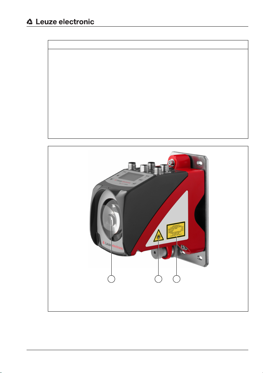
Safety
A Laser aperture
B Laser warning sign
C Laser information sign with laser parameters
A B
C
NOTICE
Affix laser information and warning signs!
Laser information and warning signs are attached to the device (see figure 2.1):
In addition, self-adhesive laser warning and information signs (stick-on labels) are supplied
in several languages (see figure 2.2).
Affix the laser information sheet to the device in the language appropriate for the place
of use.
When using the device in the US, use the stick-on label with the "Complies with
21 CFR 1040.10" notice.
Affix the laser information and warning signs near the device if no signs are attached
to the device (e.g., because the device is too small) or if the attached laser information
and warning signs are concealed due to the installation position.
Affix the laser information and warning signs so that they are legible without exposing
the reader to the laser radiation of the device or other optical radiation.
Figure 2.1: Laser apertures, laser warning signs
Leuze electronic AMS 338i 9
TNT 35/7-24V
Page 13
Safety
AVOID EXPOSURE – LASER RADIATION
IS EMITTED FROM THIS APERTURE
EXPOSITION DANGEREUSE – UN RAYONNEMENT
LASER EST ÉMIS PAR CETTE OUVERTURE
LASERSTRAHLUNG
NICHT IN DEN STRAHL BLICKEN
LASER KLASSE 2
DIN EN 60825-1:2008-05
Max. Leistung (peak):
Impulsdauer:
Wellenlänge:
RADIAZIONE LASER
NON FISSARE IL FASCIO
APARRECCHIO LASER DI CLASSE 2
EN 60825-1:2007
Potenza max. (peak):
Durata dell'impulso:
Lunghezza d'onda:
LASER RADIATION
DO NOT STARE INTO BEAM
CLASS 2 LASER PRODUCT
EN 60825-1:2007
Maximum Output (peak):
Pulse duration:
Wavelength:
RAYONNEMENT LASER
NE PAS REGARDER DANS LE FAISCEAU
APPAREIL À LASER DE CLASSE 2
EN 60825-1:2007
Puissance max. (crête):
Durée d`impulsion:
Longueur d`onde:
RADIACIÓN LÁSER
NO MIRAR FIJAMENTE AL HAZ
PRODUCTO LÁSER DE CLASE 2
EN 60825-1:2007
Potencia máx. (peak):
Duración del impulso:
Longitud de onda:
RADIAÇÃO LASER
NÃO OLHAR FIXAMENTE O FEIXE
EQUIPAMENTO LASER CLASSE 2
EN 60825-1:2007
Potência máx. (peak):
Período de pulso:
Comprimento de onda:
LASER RADIATION
DO NOT STARE INTO BEAM
CLASS 2 LASER PRODUCT
IEC 60825-1:2007
Complies with 21 CFR 1040.10
Maximum Output (peak):
Pulse duration:
Wavelength:
䉏⏘戟⺓
▎䦃展⏘㧮
伊䉏⏘ℶ❐
GB7247.1-2012
㦏⮶戢⒉᧤⽿⋋᧥
厘⑁㖐兼㢅梃
㽱栎
4 mW
18 μs
655 nm
4 mW
18 μs
655 nm
4 mW
18 μs
655 nm
4 mW
18
μ
s
655 nm
4 mW
18 μs
655 nm
4 mW
18 μs
655 nm
4 mW
18 μs
655 nm
4 mW
18 μs
655 nm
50125612-01
Figure 2.2: Laser warning and information signs – supplied stick-on labels
10 AMS 338i Leuze electronic
Page 14
Fast commissioning / operating principle
3 Fast commissioning / operating principle
Notice!
Below, you will find a short description for the initial commissioning of the AMS 338i.
Detailed explanations for the listed points can be found throughout the handbook.
3.1 Mounting the AMS 338i
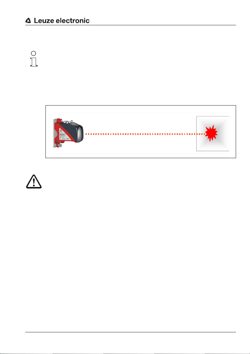
The AMS 338i and the corresponding reflector are mounted on two mutually opposing,
plane-parallel, flat walls.
Figure 3.1: Schematic illustration of mounting
Attention!
For error-free position measurement, there must be an unobstructed line-of-sight between
the AMS 338i and the reflector.
3.1.1 Mounting the device
The laser is mounted using 4 screws (M5).
Alignment is performed using 2 adjustment screws. Adjust so that the laser light spot is positioned at the center of the reflector. The alignment is to be secured with the knurled nut and
locked with the M5 nut.
Further information can be found in chapter 5.2 and chapter 5.3.
3.1.2 Mounting the reflector
The reflector is mounted using 4 screws (M5). The reflector is angled using the spacer
sleeves included. Incline the reflector by approx. 1°.
Detailed information can be found in chapter 6.4.
Leuze electronic AMS 338i 11
TNT 35/7-24V
Page 15

Fast commissioning / operating principle
3.2 Connecting the voltage supply
The laser measurement system is connected using M12 connectors. The voltage supply is
connected via the PWR M12 connection (18 … 30 VDC). 2 freely programmable switching
inputs/outputs for individual adaptation to the respective application are also available here.
Detailed information can be found in chapter 7.
3.3 Display
Once the laser measurement system is supplied with voltage, the device status as well as
the measured position values can be read on the display. The display automatically switches
to the display of the measurement values.
Use the up/down buttons to the left of the display to read and change a wide range
of data and parameters.
Detailed information can be found in chapter 8.
3.4 AMS 338i on the EtherCat
Detailed information can be found in chapter 9.
12 AMS 338i Leuze electronic
Page 16

Specifications
4 Specifications
4.1 Specifications of the laser measurement system
4.1.1 General specifications AMS 338i
Measurement data AMS 338i 40 (H) AMS 338i 120 (H) AMS 338i 200 (H) AMS 338i 300 (H)
Measurement range 0.2 … 40m 0.2 … 120m 0.2 … 200m 0.2 … 300m
Accuracy ± 2mm ± 2mm ± 3mm ± 5mm
Consistency
Light spot diameter ≤ 40mm ≤ 100 mm ≤ 150 mm ≤ 225mm
Measurement value output
Integration time 8ms
Resolution adjustable, see chapter of the individual interfaces
Temperature drift ≤ 0.1 mm/K
Ambient temperature sensitivity 1ppm/K
Air pressure sensitivity 0.3ppm/hPa
Tra ve rs e rate ≤ 10 m/s
Electrical data
Supply voltage Vin
Current consumption without device heating: ≤ 250 mA / 24V DC
Optical data
Transmitter laser diode, red light, wavelength 650 … 690nm
Laser class 2 acc. to EN 60825-1, CDRH
Interfaces
Interface type EtherCAT
Baud rate 100Mbit/s
Vendor ID 0x121
Device type 0x00080196h (absolute linear encoder)
Operating and display elements
Keyboard 4 buttons
Display monochromatic graphical display, 128 x 64 pixels
LED 4 LEDs, 2 of which are used to display the EtherCAT connection
1)
0.3mm 0.5mm 0.7mm 1.0mm
1.7ms
2)
18 … 30V DC
with device heating: ≤ 500 mA / 24VDC
or 289
h
Dec
TNT 35/7-24V
Leuze electronic AMS 338i 13
Page 17

Specifications
Inputs/outputs
Quantity
Input
Output
Mechanical data
Housing cast zinc and aluminum
Optics glass
Weight approx. 2.45kg
Protection class
Environmental conditions
Operating temperature
without device heating
with device heating
Storage temperature -30°C … +70°C
Air humidity max. 90% rel. humidity, non-condensing
Mechanical/electrical loading capacity
Vibrations acc. to EN 60068-2-6
Noise acc. to EN 60060-2-64
Shock acc. to EN 60068-2-27
EMC
1) Statistical error: 1 sigma; minimum switch-on time: 2min.
2) For UL applications: only for use in "Class 2" circuits acc. to NEC.
3) With screwed-on M12 plugs or mounted caps.
4) With devices with heating, the switch on/off area of the internal heating can be extended to prevent
condensation from forming. A 100% prevention of the formation of condensation cannot be guaranteed due to the limited heating capacity of the AMS 338i.
5) This is a Class A product. In a domestic environment this product may cause radio interference, in
which case the operator may be required to take adequate measures.
acc. to EN 61000-6-2 and EN 61000-6-4
2, programmable
protected against polarity reversal
max. 60mA, short-circuit proof
IP 65 acc. to EN 60529
3)
-5°C … +50 °C
-30°C…+50°C
4)
5)
The AMS 338i is designed in accordance with safety class III for supply with
PELV (protective extra-low voltage).
14 AMS 338i Leuze electronic
Page 18
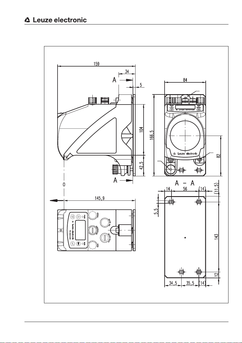
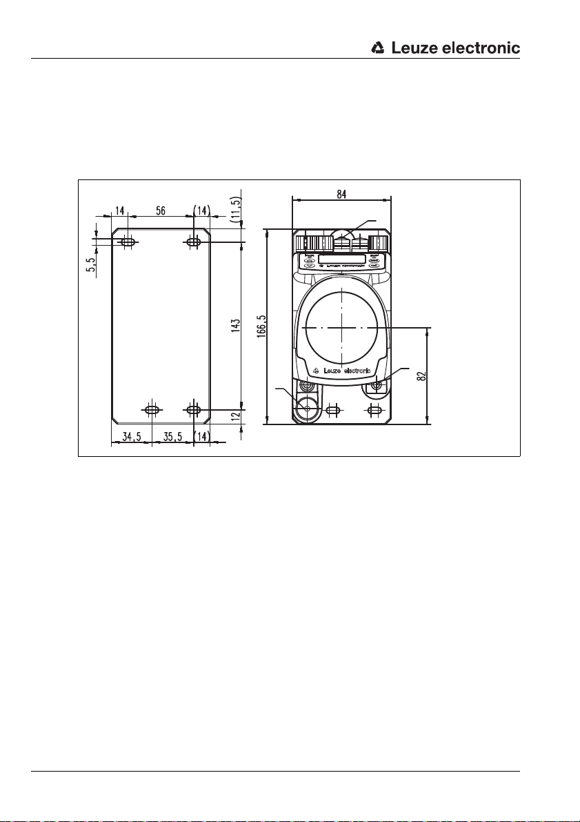
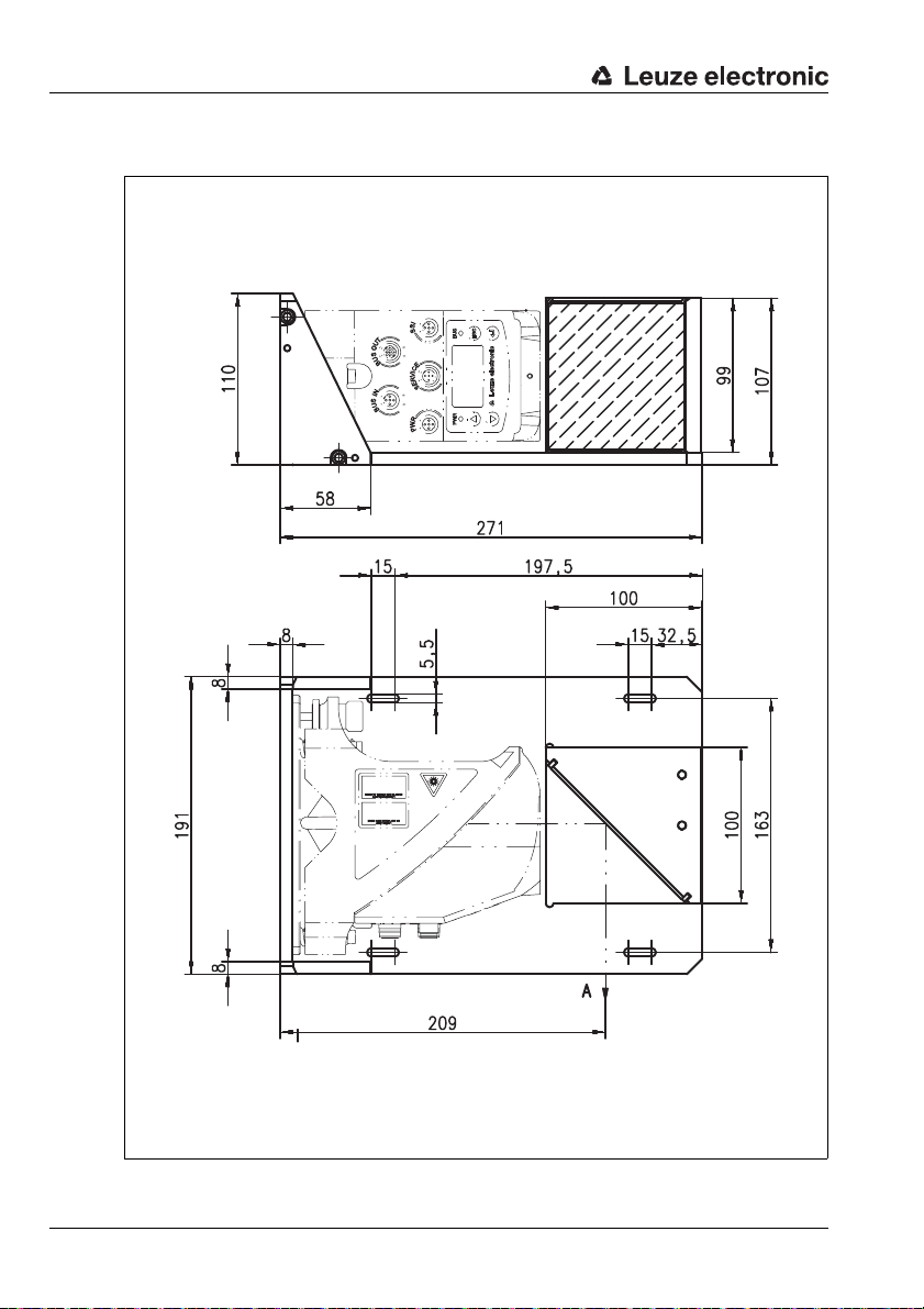
4.1.2 Dimensioned drawing AMS 338i
A M5 screw for alignment
B Knurled nut with WAF4
hexagon socket and M5 nut for securing
C Optical axis
D Zero point of the distance to be measured
A
B
D
A
C
Specifications
Leuze electronic AMS 338i 15
Figure 4.1: Dimensioned drawing AMS 338i
TNT 35/7-24V
Page 19

Specifications
4.1.3 Type overview AMS 338i
AMS 338i (EtherCAT)
Type designation Description Part no.
AMS 338i 40 40m operating range, EtherCAT interface 50113701
AMS 338i 120 120m operating range, EtherCAT interface 50113702
AMS 338i 200 200m operating range, EtherCAT interface 50113703
AMS 338i 300 300m operating range, EtherCAT interface 50113704
AMS 338i 40 H 40m operating range, EtherCAT interface, integrated heating 50113705
AMS 338i 120 H 120m operating range, EtherCAT interface, integrated heating 50113706
AMS 338i 200 H 200m operating range, EtherCAT interface, integrated heating 50113707
AMS 338i 300 H 300m operating range, EtherCAT interface, integrated heating 50113708
Table 4.1: Type overview AMS 338i
16 AMS 338i Leuze electronic
Page 20
5 Installation and mounting
5.1 Storage, transportation
Attention!
When transporting or storing, package the device s o that it i s protected against collision and
humidity. Optimum protection is achieved when using the original packaging. Heed the required environmental conditions specified in the technical data.
Unpacking
Check the packaging for any damage. If damage is found, notify the post office or shipping
agent as well as the supplier.
Check the delivery contents using your order and the delivery papers:
• Delivered quantity
• Device type and model as indicated on the nameplate
• Brief manual
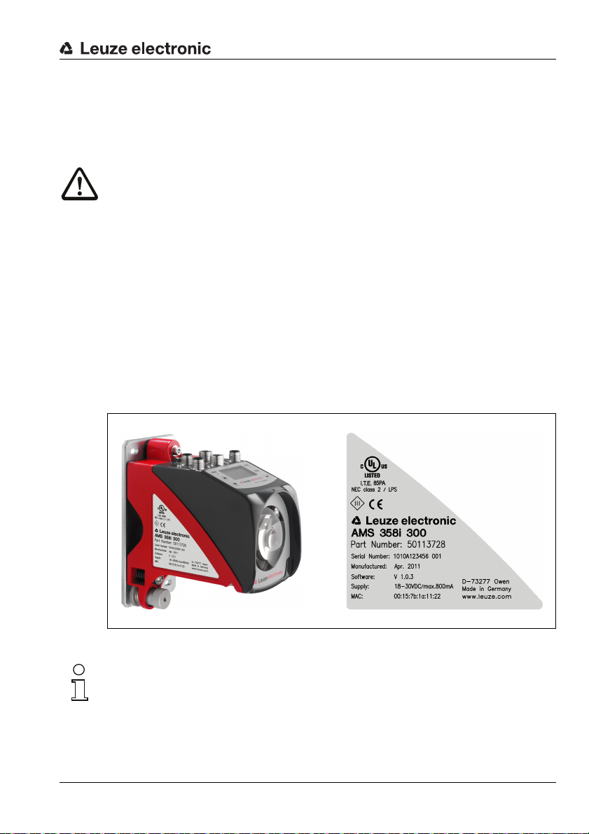
The name plate provides information as to what AMS 338i type your device is. For specific
information, please refer to chapter 11.1.1.
Name plates
Installation and mounting
Figure 5.1: Device name plate using the AMS 300i as an example
Notice!
Please note that the shown name plate is for illustration purposes only; the contents do not
correspond to the original.
Save the original packaging for later storage or shipping.
Leuze electronic AMS 338i 17
TNT 35/7-24V
Page 21
Installation and mounting
A M5 screw for align-
ment
B Knurled nut and nut
with WAF4 hexagon
socket for securing
C Optical axis
A
B
A
C
If you have any questions concerning your shipment, please contact your supplier or your
local Leuze electronic sales office.
Observe the applicable local regulations when disposing of the packaging materials.
5.2 Mounting the AMS 338i
Figure 5.2: Mounting the device
The AMS 338i and the corresponding reflector are mounted on two mutually opposing,
plane-parallel, flat walls or system parts. For error-free position measurement, there must
be an unobstructed line-of-sight connection between the AMS 338i and the reflector.
Use M5 screws to fasten the laser measurement system. Secure the screws with a toothed
lock washer to protect against loosening caused by vibrations.
18 AMS 338i Leuze electronic
Page 22
Installation and mounting
Aligning the laser light spot in the center of the reflector
The laser light spot has to be aligned so that it always hits the center of the opposing
reflector, both at close range as well as at the maximum measurement distance. To align,
use the two M5 Allen screws ("A" in figure 5.2). When aligning please ensure that the
knurled nut and the lock nut ("B" in figure 5.2) are opened wide.
Attention!
To prevent the laser measurement system from moving out of alignment during continuous
operation, subsequently hand-tighten the knurled nut and counterlock with the nut with
WAF4 hexagon socket ("B" in figure 5.2). Knurled nut and nut must not be tightened until
alignment has been completed.
Attention!
The device must not be opened. Failure to comply will render the guarantee void. Warranted
features cannot be guaranteed after the device has been opened.
Leuze electronic AMS 338i 19
TNT 35/7-24V
Page 23
Installation and mounting
A Laser beam
5.2.1 Optional mounting bracket
A mounting bracket for mounting the AMS 338i on a flat, horizontal surface is available as
an optional accessory.
Type designation: MW OMS/AMS 01
Part no.: 50107255
Figure 5.3: Optional mounting bracket
20 AMS 338i Leuze electronic
Page 24
5.2.2 Parallel mounting of the AMS 338i
Reflector 1 Reflector 2
Definition of the term "parallel spacing"
As shown in figure 5.4, dimension X describes the "parallel spacing" of the inner edges of
the two laser light spots on the reflector.
Figure 5.4: Minimum parallel spacing X between adjacent AMS 338i
The diameter of the light spot increases with distance.
AMS 338i 40 (H) AMS 338i 120 (H) AMS 338i 200 (H) AMS 338i 300 (H)
Installation and mounting
X
Max. measurement distance
Light spot diameter ≤ 40mm ≤ 100 mm ≤ 150 mm ≤ 225mm
Thus, the center-to-center spacing of the two AMS 338i devices with respect to one another
can be calculated as a function of the maximum measurement distance.
To define the minimum parallel spacing between two AMS 338i, it is necessary to distinguish
between three different arrangements of AMS 338i and reflectors.
40m 120m 200m 300m
The AMS 338i are mounted stationary and in parallel on one plane. Both reflectors move independently of one another at different distances to the AMS 338i.
Minimum parallel spacing X of the two laser light spots:
X = 100mm + (max. measurement distance in mm x 0.01)
The AMS 338i are mounted stationary and in parallel on one plane. Both reflectors move in parallel at the same distance to the AMS 338i.
Measurement distance up to 120 m: minimum parallel spacing X ≥ 600 mm
Measurement distance up to 200 m: minimum parallel spacing X ≥ 750 mm
Measurement distance up to 300 m: minimum parallel spacing X ≥ 750 mm
Leuze electronic AMS 338i 21
TNT 35/7-24V
Page 25

Installation and mounting
The reflectors are mounted stationary and in parallel on one plane.
Both AMS 338i move independently of one another at different or the same distances to the reflectors.
Measurement distance up to 120m: minimum parallel spacing X ≥ 600mm
Measurement distance up to 200m: minimum parallel spacing X ≥ 750mm
Measurement distance up to 300m: minimum parallel spacing X ≥ 750mm
Notice!
Please note that when the AMS 338i are mounted in a mobile manner, travel tolerances could
cause the two laser light spots to move towards each other.
Take the travel tolerances of the vehicle into account when defining the parallel spacing of
adjacent AMS 338i.
5.2.3 Parallel mounting of AMS 338i and DDLS optical data transmission
The optical data transceivers of the DDLS series and the AMS 338i do not interfere with one
another. Depending on the size of the used reflector, the DDLS can be mounted with a
minimum parallel spacing of 100 mm to the AMS 338i. The parallel spacing is independent
of the distance.
22 AMS 338i Leuze electronic
Page 26
Installation and mounting
5.3 Mounting the AMS 338i with laser beam deflector unit
General information
The two available deflector units are used for the 90° deflection of the laser beam,
see "Accessory deflector unit" on page 85.
Attention!
The deflector units are designed for a maximum range of 40m.
Longer distances on request.
5.3.1 Mounting the laser beam deflector unit With integrated mounting bracket
The AMS 338i is screwed onto the mechanism of the US AMS 01 deflector unit. The mirror
can be mounted for three deflection directions:
1. Upward beam deflection
2. Beam deflection to the left
3. Beam deflection to the right
The deflector unit is mounted on plane-parallel, flat walls or plant components. For errorfree position measurement, there must be an interruption-free line-of-sight between the
AMS 338i… and the deflection mirror as well as between the mirror and the reflector.
Use the M5 screws to mount the deflector unit. Secure the screws with a toothed lock
washer to protect against loosening caused by vibrations.
Figure 5.5: Mounting variants of the US AMS 01 laser beam deflector unit
Leuze electronic AMS 338i 23
TNT 35/7-24V
Page 27
Installation and mounting
A Laser beam
5.3.2 Dimensioned drawing of US AMS 01 deflector unit
Figure 5.6: Dimensioned drawing of US AMS 01 deflector unit
24 AMS 338i Leuze electronic
Page 28
Installation and mounting
A Mirror
Height of the spring in
non-preloaded state
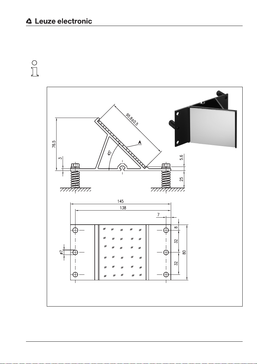
5.3.3 Mounting the US 1 OMS deflector unit without mounting bracket
The US 1 OMS deflector unit and the AMS 338i are mounted separately.
Notice!
When mounting, make certain that the laser light spot of the AMS 338i is aligned in the center
of the deflection mirror.
Figure 5.7: Photo and dimensioned drawing of the US 1 OMS deflector unit
Alignment of the laser light spot on the reflector is performed as described in chapter 5.2.
Leuze electronic AMS 338i 25
TNT 35/7-24V
Page 29

Reflectors
6 Reflectors
6.1 General information
The AMS 338i measures distances against a reflective tape specified by Leuze electronic.
All provided specifications for the AMS 338i, such as the operating range or accuracy, can
only be achieved with the reflective tape specified by Leuze electronic.
The reflective tapes are available as adhesive tapes, affixed to a metal plate and with an
integrated heater especially for use at low temperatures. Reflective tapes with heating have
the designation "Reflective tape …x…-H", where "H" is an abbreviation for the heating
variant.
The reflective tapes/reflectors must be ordered separately. The choice of size is left to the
user. In chapter 6.3, recommendations on reflector size are provided as a function of the
distance that is to be measured. In any case, the user must check to determine whether the
recommendation is suitable for the respective application.
6.2 Description of the reflective tape
The reflective tape consists of a white, microprism-based reflective material. The microprisms are protected with a highly transparent, hard protective layer.
Under certain circumstances, the protective layer may lead to surface reflections. The
surface reflections can be directed past the AMS 338i by positioning the reflective tape at
a slight incline. The inclination of the reflective tape/reflectors is described in chapter 6.4.2.
The required pitch can be found in table 6.1 "Reflector pitch resulting from spacer sleeves"
on page 35.
The reflective tapes are provided with a protective foil that can easily be pulled off. This must
be removed from the reflector before the complete system is put into operation.
26 AMS 338i Leuze electronic
Page 30

6.2.1 Specifications of the self-adhesive foil
Part
Type designation
Part no. 50104361 50104362 50108988
Foil size 200x 200mm 500 x500 mm 914 x914 mm
Recommended application temperature for adhesive tape
Temperature resistance,
affixed
Mounting surface The mounting surface must be clean, dry and free of grease.
Cutting the tape Cut with a sharp tool, always on the side of the prism structure.
Cleaning
Storing the foil Store in a cool and dry place.
Reflective tape
200x200-S
Do not use any agents that act with a grinding effect. A conventional household
detergent can be used as a cleaning agent. Rinse with clear water and dry the
Reflective tape
500x500-S
+5°C … +25°C
-40°C…+80°C
surface.
6.2.2 Specifications of the reflective tape on a metal plate
The reflective tape is affixed to a metal plate. Included with the metal plate are spacers for
positioning at an incline - for avoiding surface reflections - (see chapter 6.4.2 "Mounting the
reflector").
Reflectors
Reflective tape
914x914-S
Part
Type designation
Part no. 50104364 50104365 50104366
Foil size 200x 200mm 500 x500 mm 914 x914 mm
Outer dimensions of the
metal plate
Weight 0.8kg 4kg 25kg
Cleaning
Storing the reflector Store in a cool and dry place.
Leuze electronic AMS 338i 27
Reflective tape
200x200-M
250x 250mm 550 x550 mm 964x964 mm
Do not use any agents that act with a grinding effect. A conventional household
detergent can be used as a cleaning agent. Rinse with clear water and dry the
Reflective tape
500x500-M
surface.
Reflective tape
914x914-M
TNT 35/7-24V
Page 31

Reflectors
Always align the TOP marking
with the AMS connections!
(chapter 6.4.2)
6.2.3 Dimensioned drawing of reflective tape on a metal plate
Figure 6.1: Dimensioned drawing of reflectors
Part Reflective tape (mm) Reflector plate (mm)
xL yL XL YL L
Reflective tape 200x200-M 200 200 250 250 214
Reflective tape 500x500-M 500 500 550 550 514
Reflective tape 914x914-M 914 914 964 964 928
28 AMS 338i Leuze electronic
Page 32

6.2.4 Specifications of heated reflectors
The reflective tape is affixed to a heated, thermally insulated base. The insulation results in
a very high energetic efficiency.
Only the reflective tape is kept at the specified temperature by the integrated heater.
Through the insulation on the back, the generated heat cannot be transferred via the steel
construction. Energy costs are greatly reduced in the case of continuous heating.
Type designation
Part no. 50115020 50115021 50115022
Voltage supply 230VAC
Power 100W 600W 1800 W
Current consumption ~ 0.5A ~ 3A ~ 8A
Length of the supply line 2 m
Size of the reflective tape 200x200 mm 500 x500 mm 914 x914mm
Outer dimensions of the base
material
Weight 0.5kg 2.5 kg 12 kg
Temperature control
Switch-on temperature ~ 5 °C
Switch-off temperature ~ 20°C
Operating temperature -30°C … +70°C
Storage temperature -40°C … +80°C
Air humidity Max. 90%, non-condensing.
Cleaning
Storing the reflector Store in a cool and dry place.
Reflective tape
200x200-H
250x 250mm 550x 550mm 964x 964mm
Controlled heating with the following switch-on and switch-off tempera-
Do not use any agents that act with a grinding effect. A conventional household detergent can be used as a cleaning agent. Rinse with clear water and
Part
Reflective tape
500x500-H
tures, measured at the reflector surface.
dry the surface.
Reflective tape
Reflectors
914x914-H
TNT 35/7-24V
Leuze electronic AMS 338i 29
Page 33

Reflectors
18
6,5
2
L ± 0,5
XL ± 1
TOP
6
2000
115
90
XL ± 1
yL ± 1
L ± 0,5
YL ± 1
Always align the TOP marking
with the AMS connections!
(chapter 6.4.2)
Connection hood
Reflective tape
Si cable
3 x 0.75mm²
6.2.5 Dimensioned drawing of heated reflectors
Figure 6.2: Dimensioned drawing of heated reflectors
Reflective tape 200x200-H 200 200 250 250 214
30 AMS 338i Leuze electronic
Reflective tape 500x500-H 500 500 550 550 514
Reflective tape 914x914-H 914 914 964 964 928
Part Reflective tape (mm) Insulated base plate (mm)
xL yL XL YL L
Page 34

6.3 Selecting reflector sizes
Depending on system design, the reflector can be mounted so that it travels on the vehicle
or it can be mounted at a fixed location.
Attention!
The reflector sizes shown below are a recommendation from Leuze electronic for on-vehicle
mounting of the AMS 338i. For stationary mounting of the AMS 338i, a smaller reflector is
generally sufficient for all measurement distances.
On the basis of the system planning and design, always check whether mechanical travel
tolerances may require the use of a reflector larger than that which is recommended. This
applies, in particular, when the laser measurement system is mounted on a vehicle. During
travel, the laser beam must reach the reflector without interruption. For on-vehicle mounting
of the AMS 338i, the reflector size must accommodate any travel tolerances that may arise
and the associated "wandering" of the light spot on the reflector.
Overview of reflector types
AMS 338i selection
(Operating range in m)
AMS 338i 40 (max. 40 m) 200x200mm Reflective tape 200x200-S
AMS 338i 120 (max. 120m) 500x 500mm Reflective tape 500x500-S
AMS 338i 200 (max. 200m) 749x914mm
AMS 338i 300 (max. 300m) 749x914mm
Recommended reflector sizes
Recommended
reflector size
(H x W)
914x 914mm
914x 914mm
Type designation
…-S = Self-adhesive
…-M = metal plate
…-H = heating
Reflective tape 200x200-M
Reflective tape 200x200-H
Reflective tape 500x500-M
Reflective tape 500x500-H
Reflective tape 749x914-S
Reflective tape 914x914-M
Reflective tape 914x914-S
Reflective tape 914x914-H
Reflective tape 749x914-S
Reflective tape 914x914-M
Reflective tape 914x914-S
Reflective tape 914x914-H
Reflectors
Part no.
50104361
50104364
50115020
50104362
50104365
50115021
50104363
50104366
50108988
50115022
50104363
50104366
50108988
50115022
TNT 35/7-24V
Leuze electronic AMS 338i 31
Page 35

Reflectors
6.4 Mounting the reflector
6.4.1 General information
Self-adhesive reflective tapes
The reflective tapes of the "Reflective tape …x…-S" self-adhesive series must be affixed
to a flat, clean and grease-free surface. We recommend using a separate metal plate, which
is to be provided on-site.
As described in table 6.1, the reflective tape must be angled.
Reflective tapes on metal
The reflective tapes of the "Reflective tape …x…-M" series are provided with corresponding
mounting holes. Spacer sleeves are provided in the packet for achieving the necessary pitch
angle. For further information see table 6.1.
Heated reflectors
The reflective tapes of the "Reflective tape ...x...-H" series are provided with corresponding
mounting holes. Due to the voltage supply affixed on the rear, the reflector cannot be
mounted flat. Included in the package are four distance sleeves in two different lengths. Use
the distance sleeves to achieve a base separation to the wall as well as the necessary pitch
for avoiding surface reflection. For further information see table 6.1.
The reflector is provided with a 2 m-long connection cable for supplying with 230V AC.
Connect the cable to the closest power outlet. Observe the current consumptions listed in
the specifications.
Attention!
Connection work must be carried out by a certified electrician.
6.4.2 Mounting the reflector
The combination of laser measurement system and reflective tape/reflector is mounted so
that the laser light spot hits the tape as centered as possible and without interruption.
For this purpose, use the alignment elements provided on the AMS 338i… (see chapter 5.2
"Mounting the AMS 338i"). If necessary, remove the protective foil from the reflector.
Attention!
The "TOP" label mounted on the reflectors should be aligned the same as the connections
of the AMS 338i.
Example:
If the AMS 338i is mounted so that the M12 connections are on the top, the "TOP" label of
the reflector is also on the top. If the AMS 338i is mounted so that the M 12 connections are
on the side, the "TOP" label of the reflector is also on the side.
32 AMS 338i Leuze electronic
Page 36

Reflectors
Pitch approx. 1°
Direct reflection from the
triad structure
Deflected surface reflection due to
the pitch of the reflective tape
Pitch approx. 1°
Spacer sleeves
Notice!
The reflector must be angled. To do this, use the spacer sleeves. Angle the reflectors so that
the surface reflections of the foil seal are deflected to the left, right or upwards, chapter
6.4.3 gives the correct pitch with respect to the reflector size and, thus, the length of the
spacers.
Reflective tapes …-S and …-M
Figure 6.3: Reflector mounting
Figure 6.4: Pitch of the reflector
Leuze electronic AMS 338i 33
TNT 35/7-24V
Page 37

Reflectors
Pitch approx. 1°
Deflected surface reflection due to
the pitch of the reflective tape
Direct reflection from the
triad structure
Pitch approx. 1°
Spacer sleeves
Reflective tapes …-H
Figure 6.5: Mounting of heated reflectors
Figure 6.6: Pitch of the heated reflector
34 AMS 338i Leuze electronic
Page 38

6.4.3 Table of reflector pitches
Reflectors
Reflector type Pitch resulting from spacer sleeves
Reflective tape 200x200-S
Reflective tape 200x200-M
Reflective tape 200x200-H 2 x 15mm 2 x 20mm
Reflective tape 500x500-S
Reflective tape 500x500-M
Reflective tape 500x500-H 2 x 15mm 2 x 25mm
Reflective tape 749x914-S 2x20mm
Reflective tape 914x914-S
Reflective tape 914x914-M
Reflective tape 914x914-H 2 x 15mm 2 x 35mm
1) Spacer sleeves are included in the delivery contents of reflective tape …-M and …-H
Table 6.1: Reflector pitch resulting from spacer sleeves
Notice!
Reliable function of the AMS 338i and, thus, max. operating range and accuracy can only
be achieved with the reflective tape specified by Leuze electronic. No function can be guaranteed if other reflectors are used!
2x5mm
2x10mm
2x20mm
1)
Leuze electronic AMS 338i 35
TNT 35/7-24V
Page 39

Electrical connection
Leuze SERVICE
M12 socket
(A-coded)
PWR / IOs
M12 connector
(A-coded)
BUS IN
M12 socket
(D-coded)
BUS OUT
M12 socket
(D-coded)
7 Electrical connection
The AMS 338i laser measurement systems are connected using variously coded M12
connectors. This ensures unique connection assignments.
Notice!
The corresponding mating connectors and ready-made cables are available as accessories
for all cables. For further information, see chapter 11 "Type overview and accessories".
Figure 7.1: Connections of the AMS 338i
7.1 Safety notices for the electrical connection
Attention!
Before connecting the device, be sure that the supply voltage agrees with the value printed
on the name plate.
The device may only be connected by a qualified electrician.
Ensure that the functional earth (FE) is connected correctly. Unimpaired operation is only
guaranteed when the functional earth is connected properly.
If faults cannot be corrected, the device should be removed from operation and protected
against possible use.
Attention!
For UL applications, use is permitted exclusively in Class 2 circuits according to NEC (National Electric Code).
The laser measurement systems are designed in accordance with safety class III for supply
by PELV (protective extra-low voltage with reliable disconnection).
Notice!
Protection class IP65 is achieved only if the connectors and caps are screwed into place!
36 AMS 338i Leuze electronic
Page 40

Described in detail in the following are the individual connections and pin assignments.
PWR
I/O 2
I/O 1
3
2
1
4
5
GND VIN
FE
M12 plug
(A-coded)
M12 socket
(D-coded)
7.2 PWR – voltage supply / switching input/output
PWR (5-pin plug, A-coded)
Pin Name Remark
1 VIN Positive supply voltage +18 … +30VDC
2 I/O 1 Switching input/output 1
3 GND Negative supply voltage 0 VDC
4 I/O 2 Switching input/output 2
5 FE Functional earth
Thread FE Functional earth (housing)
Table 7.1: Pin assignment PWR
Further information on configuring the input/output can be found in chapter 8 and chapter 9.
7.3 EtherCAT BUS IN
BUS IN (4-pin socket, D-coded)
Pin Name Remark
1 TD+ Transmit Data +
2 RD+ Receive Data +
3 TD- Transmit Data -
4 RD- Receive Data -
Thread FE Functional earth (housing)
TD+
BUS IN
RD+
2
1
4
RD-
TD-
3
Electrical connection
TNT 35/7-24V
Leuze electronic AMS 338i 37
Table 7.2: Pin assignments for BUS IN
Page 41

Electrical connection
BUS OUT
TD+
1
2
3
4
RD+
RD-
TD-
M12 socket
(D-coded)
M12 socket
(A-coded)
7.4 EtherCAT BUS OUT
Table 7.3: Pin assignment BUS OUT
7.5 Service
SERVICE
RS232-TX
2
NC
1
RS232-RX
GND
3
5
4
NC
BUS OUT (4-pin socket, D-coded)
Pin Name Remark
1 TD+ Transmit Data +
2 RD+ Receive Data +
3 TD- Transmit Data -
4 RD- Receive Data -
Thread FE Functional earth (housing)
Service (5-pin socket, A-coded)
Pin Name Remark
1NC Not used
2 RS232-TX Transmission line RS 232/service data
3 GND Voltage supply 0V DC
4 RS232-RX Receiving line RS 232/service data
5NC Not used
Thread FE Functional earth (housing)
Table 7.4: Service pin assignments
Notice!
The service interface is designed only for use by Leuze electronic!
38 AMS 338i Leuze electronic
Page 42

Display and control panel AMS 338i
Status display
Bar graph
LED
Bus/interface info
LED
Control buttons
Distance measurement value
8 Display and control panel AMS 338i
8.1 Structure of the control panel
Figure 8.1: Structure of the control panel using the AMS 304i PROFIBUS device variant as an example
Notice!
The figure is for illustration purposes only and does not correspond to AMS 338i with respect
to bus/interface info.
8.2 Status display and operation
8.2.1 Indicators in the display
Status and warning messages in the display
IO1 Input 1 or output 1 active:
IO2 Input 2 or output 2 active:
Leuze electronic AMS 338i 39
Function depending on configuration.
Function depending on configuration.
TNT 35/7-24V
Page 43

Display and control panel AMS 338i
Activated interface
Maximum position value
IO1 LSR PLB ECAT
IO2 TMP ATT
ERR
+ 87.000m
LSR Warning - laser prefailure message:
Laser diode old, device still functional, exchange or have repaired.
TMP Warning - temperature monitoring:
Permissible internal device temperature exceeded / not met.
PLB Plausibility error:
Implausible measurement value. Possible causes: light beam interruption, outside
of measurement range, permissible internal device temperature considerably
exceeded or traverse rate >10m/s.
Depending on the configuration, either zero or the last valid measurement value is
output at the interfaces.
ATT Warning received signal:
Laser outlet window or reflector soiled or fogged by rain, water vapor or fog. Clean
or dry surfaces.
ERR Internal hardware error:
The device must be sent in for inspection.
Bar graph
Indicates the strength of the received laser light.
The center bar represents the ATT warning threshold. The distance value remains
valid and is output at the interfaces.
If no bar graph is available, the PLB status information appears at the same time.
The measurement value has thus been assessed as being implausible. Depending
on the configuration, either zero or the last valid measurement value is output at the
interfaces.
Interface info
The abbreviation "ECAT" indicates an activated EtherCAT interface.
Maximum position value
The measured position value is displayed in the configured unit of measurement.
+87.000m With the metric setting, the measurement value is always displayed in meters
with three decimal places.
+87.0in With the inch setting, the measurement value is always displayed in inches
with one decimal place.
40 AMS 338i Leuze electronic
Page 44

8.2.2 LED status displays
PWR LED
Off Device OFF
Flashing green Power LED flashes green
Green continuous light Power LED green
Red flashing Power LED flashes red
Display and control panel AMS 338i
- No supply voltage
- No measurement value output
- Voltage connected
- Self test running
- Initialization running
- Boot process running
- AMS 338i ok
- Measurement value output
- Self test successfully finished
- Device monitoring active
- Device ok but warning message (ATT, TMP, LSR)
set in display
- Light beam interruption
- Plausibility error (PLB)
Red continuous light Power LED red
- No measurement value output; for details, see
Display
Orange continuous light Power LED orange
- Parameter enable active
- No data on the host interface
BUS LED
Off BUS LED off
- No voltage supply
-Bus ok
Leuze electronic AMS 338i 41
TNT 35/7-24V
Page 45

Display and control panel AMS 338i
Net
LINK LED for BUS IN LINK LED for BUS OUT
Flashing green BUS LED flashes green
Green continuous light BUS LED green
Flashing green/red BUS LED flashes green/red
Flashing red BUS LED flashes red
LINK LED for BUS IN and BUS OUT
A green/yellow multicolor LED below the BUS IN and BUS OUT connectors indicates the
EtherCAT connection status.
-“PRE-OPERATIONAL” state
- “SAFE-OPERATIONAL” state
-“OPERATIONAL” state
-Bus error
-Time out
-Process Data Watchdog Timeout
- Invalid configuration
-
Green continuous light LINK LED green
- The link exists, the hardware connection to the next
connected participant is OK.
Flashing yellow LINK LED flashes yellow
- Data is exchanged with the connected participants.
42 AMS 338i Leuze electronic
Page 46

8.2.3 Control buttons
ESC
Delete character
Enter digit
Save
Display and control panel AMS 338i
Up Navigate upward/laterally.
Down Navigate downward/laterally.
ESC
ESC Exit menu item.
ENTER Confirm/enter value, change menu levels.
Navigating within the menus
The menus within a level are selected with the up/down buttons .
The selected menu item is activated with the enter button .
Press the ESC button to move up one menu level.
When one of the buttons is actuated, the display illumination is activated for 10min.
Setting values
If input of a value is possible, the display looks like this:
100
<-|0123456789 save
Default ----------------- unit
126 | |
Use the and buttons to set the desired value. An accidental, incorrect entry can
be corrected by selecting <-| and then pressing .
Then use the buttons to select Save and save the set value by pressing .
Selecting options
If options can be selected, the display looks like this:
TNT 35/7-24V
o OFF
ON
Default ----------------- unit
OFF | |
Select the desired option with the buttons. Activate the option by pressing .
Leuze electronic AMS 338i 43
Page 47

Display and control panel AMS 338i
8.3 Menu description
8.3.1 The main menus
After voltage has been applied to the laser, device information is displayed for several
seconds. The display then shows the measurement window with all status information.
AMS 338i 120
Leuze electronic
SW: V 1.3.0 HW:1
SN: ---------------
GmbH & Co. KG
Device information - main menu
This menu item contains detailed information on
• Device model,
• Manufacturer,
• Software and hardware version,
• Serial number.
No entries can be made via the display.
Network information
Address: 1
Alias: 1
Status: INIT, PRE, SAFE, O
P
IO1 LSR PLB ECAT
IO2 TMP ATT
ERR
+ 87.000m
Parameter
Parameter handling
EtherCAT
Maximum position value
I/O
Other
Language
selection
o Deutsch
o English
o Español
o Français
Service
Status messages
Diagnostics
Expanded diagnostics
Network information - main menu
• Explanations of address, alias, status.
No entries can be made via the display.
Status and measurement data - main menu
• Display of status-, warning-, and error messages
• Status overview of the switching inputs/outputs.
• Bar graph for the reception level.
•Link.
• Measurement value.
No entries can be made via the display.
See "Indicators in the display" on page 39..
Parameter - main menu
• Configuration of the AMS.
See "Parameter menu" on page 45.
Language selection - main menu
• Selection of the display language.
See "Language selection menu" on page 48.
Service - main menu
• Display of status messages.
• Display of diagnostic data.
No entries can be made via the display.
See "Service menu" on page 49.
44 AMS 338i Leuze electronic
Page 48

Notice!
The rear cover of this manual includes a fold-out page with the complete menu structure.
It describes the menu items in brief.
8.3.2 Parameter menu
Parameter handling submenu
The following functions can be called up in the Parameter handling submenu:
• Lock and enable parameter entry
• Set up a password
• Reset the AMS 338i to default settings.
Table 8.1: Parameter handling submenu
Display and control panel AMS 338i
Level 3 Level 4 Level 5 Selection/configuration option
Parameter
enabling
Password Activate
Parameters to
default
password
Password
entry
Description
ON / OFF
The standard setting (OFF) prevents unintended parameter changes.
With parameter enabling activated (ON), the display is inverted. In this
state, it is possible to change parameters manually.
ON / OFF
To enter a password, parameter enabling must be activated.
If a password is assigned, changes to the AMS 338i can only be made
after the password is entered.
The master password 2301 bridges the individually set password.
Configuration option of a four-digit numerical password
By pressing the enter button after selecting
Parameters to default, all parameters are reset to their standard settings without any further security prompts.
In this case, English is selected as the display language.
Standard
OFF
OFF
Additional important information on parameter handling can be found at the end of the
chapter.
EtherCAT submenu
Table 8.2: EtherCAT submenu
Level 3 Level 4 Level 5 Selection/configuration option
Activation ON / OFF ON
Address
(station alias)
Description
Configuration option 0 - 65535 0
Standard
Note regarding the second station address - in short SSA- (formerly station alias)
The SSA is a freely configurable position-independent address which is often used for the
so-called hot connect. The values range from 0 to 65535. The SSA is persistently stored on
the AMS 338i and is available after the next boot-up. A second option is to write the SSA
to the Eeprom and the associated ESC register via the master (typically TwinCAT). In this
TNT 35/7-24V
Leuze electronic AMS 338i 45
Page 49

Display and control panel AMS 338i
case, too, the SSA is persistently stored in the AMS 338i. The master (TwinCAT) can determine whether it wants to use the EtherCAT address (auto-increment address) or the SSA to
address the AMS. For SSA, the position-dependent EtherCAT address is also set to the value
of the SSA. Otherwise, the auto-increment address is entered into the ESC register which
contains the EtherCAT address. The EtherCAT address is not stored in persistence memory,
but written into the respective register by the master when the status changes from INIT to
PREOP.
Position value submenu
Notice!
All parameters mentioned must be entered via startup parameters of the control software
(TwinCAT). If parameters from the position value submenu are changed via the display, these
are overwritten via the startup sequence created in the control with the values stored there.
Table 8.3: Position value submenu
Level 3 Level 4 Level 5 Selection/configuration option
Measurement
unit
Count direction Positive/Negative
Offset Output value=measurement value+offset.
Preset The preset value is accepted by means of teach pulse. The teach pulse
Free resolution
value
Error delay ON / OFF
Position value in
the case of error
Description
Metric/Inch
Specifies the units of the measured distances
Positive: The measurement value begins at 0 and increases with increasing distance.
Negative: The measurement value begins at 0 and decreases with
increasing distance. Negative distance values may need to be compensated with an offset or preset.
The resolution of the offset value is independent of the selected "Resolution position" and is entered in mm or inch/100. The offset value is
effective immediately following entry. If the preset value is activated, this
has priority over the offset. Preset and offset are not offset against each
other.
can be applied to a hardware input of the M12 PWR connector. The hardware input must be appropriately configured. See also configuration of
the I/Os.
The measurement value can be resolved in increments of 1/1000 within
the 5 … 50000 value range. If, e.g., a resolution of 0.875mm per digit
is required, the parameter is set to 875.
Specifies whether, in the event of an error, the position value immedia tely
outputs the value of the "Position value in the case of error" parameter
or the last valid position value for the configured error delay time.
Last valid value / zero
Specifies which position value is output after the error delay time elapses.
Standard
Metric
Positive
0mm
0mm
1000
ON/100 ms
Zero
46 AMS 338i Leuze electronic
Page 50

I/O submenu
Table 8.4: I/O submenu
Display and control panel AMS 338i
Level 3 Level 4 Level 5 Selection/configuration option
I/O 1 Port config-
I/O 2 Port config-
Limit values Upper pos.
uration
Switching
input
Switching
output
uration
Switching
input
Switching
output
limit 1
Lower pos.
limit 1
Upper pos.
limit 2
Lower pos.
limit 2
Function No function/preset teach/laser ON/OFF No function
Activation Low active/High active Low active
Function Pos. limit value 1 / Pos. limit value 2 / Velocity / Intensity (ATT) /
Activation Low active/High active Low active
Function No function/preset teach/laser ON/OFF No function
Activation Low active/High active Low active
Function Pos. limit value 1 / Pos. limit value 2 / Velocity / Intensity (ATT) /
Activation Low active/High active Low active
Activation ON / OFF OFF
Limit value
input
Activation ON / OFF OFF
Limit value
input
Activation ON / OFF OFF
Limit value
input
Activation ON / OFF OFF
Limit value
input
Description
Input/Output
Defines whether I/O 1 functions as an output or input.
Temp. (TMP) / Laser (LSR) / Plausibility (PLB) / Hardware (ERR)
The individual functions are "ORed" on the selected switching output.
Input/Output
Defines whether I/O 2 functions as an output or input.
Temp. (TMP) / Laser (LSR) / Plausibility (PLB) / Hardware (ERR)
The individual functions are "ORed" on the selected switching output.
Value input in mm or inch/100 0
Value input in mm or inch/100 0
Value input in mm or inch/100 0
Value input in mm or inch/100 0
Standard
Output
Plausibility (PLB),
hardware (ERR)
Output
Intensity (ATT),
Tem p. ( TM P) ,
Laser (LSR)
TNT 35/7-24V
Leuze electronic AMS 338i 47
Page 51

Display and control panel AMS 338i
Other submenu
Table 8.5: Other submenu
Level 3 Level 4 Level 5 Selection/configuration option
Heating control Standard (10°C … 15°C)/Extended (30° C … 35°)
Display illumination
Display contrast Weak/Medium/Strong
Service RS232 Baud rate 57.6kbit/s / 115.2 kbit/s
Format 8,e,1 / 8,n,1
8.3.3 Language selection menu
Language
selection
o Deutsch
English
o Español
o Français
There are 5 display languages available:
•German
• English
•Spanish
•French
• Italian
The AMS 338i is delivered from the factory with the display preset to English.
Description
Defines a switch-on/switch-off range for the heating control.
The extended switch-on/switch-off range for heating may provide relief
in the event of condensation problems.
There is no guarantee that no condensation will occur on the optics in the
extended switch-on/switch-off range due to the limited heating capacity.
This parameter is available as standard, but functions only for devices
with integrated heating (AMS 338i… H).
10 minutes/ON
Display illumination is switched off after 10 minutes or, if the parameter
is set to "ON", illumination is always on.
The display contrast may change at extreme temperature values. The
contrast can subsequently be adapted using the three levels.
The service interface is only available to Leuze internally.
The service interface is only available to Leuze internally.
Standard
Standard
10min.
Medium
115.2kbit/s
8,n,1
Notice!
When operating the AMS 338i on the EtherCAT, the language configured is used in the display.
To change the language, no password needs to be entered nor must password enabling
be activated. The display language is a passive operational control and is, thus, not a function parameter, per se.
48 AMS 338i Leuze electronic
Page 52

8.3.4 Service menu
Service
Status messages
Diagnostics
Expanded diagnostics
A more detailed description of the individual functions can be found in chapter 10.
8.4 Operation
Described here is an operating process using parameter enabling as an example.
Parameter enabling
During normal operation parameters can only be viewed. If parameters are to be changed,
the ON menu item in the Parameter -> Parameter handling -> Parameter enable
menu must be activated. To do this, proceed as follows:
Parameter
Parameter handling
EtherCAT
Maximum position value
I/O
Other
Parameter handling
o Parameter enabling
o Password
Parameters to default
Display and control panel AMS 338i
In the main menu, press the enter button to enter the
Parameter menu.
Use the buttons to select the Parameter
handling menu item.
Press the enter button to enter the Parameter
handling menu.
In the Parameter handling menu, use the
buttons to select the Parameter enabling
menu item.
Press the enter button to enter the Parameter
enabling menu.
Parameter enabling
o OFF
oON
In the Parameter enabling menu, use the
buttons to select the ON menu item.
Leuze electronic AMS 338i 49
TNT 35/7-24V
Page 53

Display and control panel AMS 338i
Parameter enabling
o OFF
ON
Press the enter button to switch on parameter
enabling.
The PWR LED illuminates orange; the display is
inverted. You can now set the individual parameters
on the display.
ESC ESC
Press the ESC button twice to return to the Parameter menu.
Viewing and editing parameters
As long as parameter enabling is activated, the entire AMS 338i display is inverted.
As long as parameter enabling is activated, communication between control and AMS 338i
is interrupted. The continued networking via BUS OUT is retained.
Notice!
If a password was stored, parameter enabling is not possible until this password is entered,
see "Password for parameter enabling" below.
Password for parameter enabling
Parameter entry on the AMS 338i can be protected with a password. The password can be
changed via the CoE online dictionary, object 0x2300
, sub-index 0x05h.
h
For parameter enable via the display, the password must be entered. If parameter enabling
has been activated after successfully entering the password, parameters can temporarily
be changed via the display.
After parameter enable has been deactivated, all changes made at the display are overwritten by the CoE online dictionary, object 0x2300
, sub-index 0x05h (see above). If a new
h
password has been assigned, this, too, is overwritten by the password defined in the online
dictionary.
Notice!
The master password 2301 can enable the AMS 338i at any time.
50 AMS 338i Leuze electronic
Page 54

9 EtherCAT interface
9.1 General information on EtherCAT
EtherCAT is an Ethernet-based fieldbus initialized by Beckhoff. The EtherCAT Technology
Group (ETG) is the official standardization partner of the IEC working groups.
EtherCAT has been an IEC standard since 2005.
• IEC 61158: protocols and services
• IEC 61784-2: communication profiles for the specific device classes
All EtherCAT-specific communication mechanisms are explained in detail in the standards
mentioned. The technical description of the AMS 338i will describe parts of the
IEC standard, if this serves basic understanding.
9.2 EtherCAT topology
EtherCAT permits a wide range of topologies such as line, tree, ring, star and their combinations. The bus or line structure known from the fieldbuses is thus also available for
EtherCAT.
Telegrams are transmitted on one line pair in the "processing direction" from the master to
the slave. The EtherCAT device processes the frames only in this direction and sends them
to the subsequent device until the telegram has passed through all devices. The last device
returns the telegram on the second line pair in the cable in "forward direction" back to the
master. Here, EtherCAT always forms a logical ring structure independent of the topology
installed.
From the Ethernet perspective, an EtherCAT bus segment is nothing but a single, large
Ethernet participant which receives and transmits Ethernet telegrams. However, there are
many EtherCAT slaves within the "participant", not just a single Ethernet controller.
EtherCAT interface
TNT 35/7-24V
Figure 9.1: Topology example
Leuze electronic AMS 338i 51
Page 55

EtherCAT interface
9.3 EtherCAT – General information on wiring
The wiring uses the Industrial Ethernet fieldbus cable common in industry. For the AMS 338i,
the EtherCAT connection is made via D-coded M12 connectors. A Cat. 5 Ethernet cable
should be used for wiring.
Leuze electronic offers cables ready-made and featuring a D-coded M12 connector on one
end and an open cable end at the other.
For further information, see chapter 7 "Electrical connection" and see chapter 11.3.5
"Accessory ready-made cables for EtherCAT".
The individual AMS 338i devices in a line topology are connected to each other using the
"KB ET - … - SSA" cable with ready-made D-coded M12 connectors on both ends, see
table "Order codes for EtherCAT connection cables" on page 88.
For unavailable cable lengths, you can configure your cables yourself. For this purpose,
Leuze electronic offers a D-coded M12 connector for Bus IN and Bus OUT. When doing
so, make certain that you connect TD+ on the M12 connector with RD+ on the RJ-45
connector and TD- on the M12 connector with RD- on the RJ-45 connector, respectively,
etc.
For the connection technology transition from M12 to RJ45, a "KDS ET M12 / RJ 45 W - 4P"
adapter is available.
9.4 EtherCAT – Cable lengths and shielding
Observe the following maximum cable lengths and shielding types:
Connection Interface Max. cable length Shielding
AMS – host EtherCAT 100m Absolutely required
Network from the
first AMS to the
last AMS
Table 9.1: Cable lengths and shielding
EtherCAT
The maximum segment length
must not exceed 100m for
100Base-TX Twisted Pair
(min.Cat.5)
Absolutely required
52 AMS 338i Leuze electronic
Page 56

9.5 EtherCAT electrical connection
M12 socket
(D-coded)
M12 socket
(D-coded)
BUS IN (4-pin socket, D-coded) BUS OUT (4-pin socket, D-coded)
Pin Name Remark Pin Name Remark
1 TD+ Transmit Data + 1 TD+ Transmit Data +
2 RD+ Receive Data + 2 RD+ Receive Data +
3 TD- Transmit Data - 3 TD- Transmit Data -
4 RD- Receive Data - 4 RD- Receive Data -
Thread FE Functional earth (housing) Thread FE Functional earth (housing)
BUS IN
TD+
1
2
3
4
RD+
RD-
TD-
BUS OUT
TD+
1
2
3
4
RD+
RD-
TD-
Figure 9.2: EtherCAT - electrical connection
EtherCAT interface
Notice!
For contacting BUS IN and BUS OUT, we recommend our ready-made EtherCAT cable (see
chapter 11.3.5 "Accessory ready-made cables for EtherCAT").
To establish an EtherCAT network, the AMS 338i provides a receiving bus labeled BUS IN
on the device, and a forwarding bus labeled BUS OUT. The AMS 338i can be connected to
BUS OUT or to BUS IN using a stub cable.
For the connection of two AMS 338i, the "KB ET - … - SSA" ready-made cables are pre-
ferred, see table 11.3.5 "Accessory ready-made cables for EtherCAT" on page 87.
If you use user-configurable cables, note the following:
Notice!
The entire connection cable must be shielded. The shielding connection must be at the same
potential on both ends of the data line. This prevents potential compensating currents over
the shield and possible interference coupling by compensating currents. The signal lines
must be stranded in pairs.
Leuze electronic AMS 338i 53
Use CAT 5 cable for the connection.
TNT 35/7-24V
Page 57

EtherCAT interface
Notice!
For the AMS 338i as standalone device or as the last participant in a linear topology, termination on the BUS OUT socket is not mandatory!
9.6 Starting the AMS 338i on the EtherCAT
INIT
The AMS 338i initializes itself. No direct communication between the master and AMS 338i
is possible. The EtherCAT master will transit the AMS 338i step by step into the "operational"
state.
In the status change from "INIT" to "PREOP", the TwinCAT or master writes the so-called
EtherCAT address (=station address) to the respective register of the EtherCAT slave
controller (here: AMS 338i). This EtherCAT address is typically specified in relation to the
position, i.e., the master's address is 1000, the first slave's address is 1001, etc. This is also
called the auto-increment method.
PRE-OPERATIONAL
The master and the AMS 338i exchange application-specific initializations and devicespecific parameters. In the PRE-OPERATIONAL state, configuration is initially possible via
SDOs only.
SAFE-OPERATIONAL
The "start input update" command puts the measurement system into the save-operational
state. The master produces output data, but input data are not considered. This means the
AMS 338i does not return output data (=PLC input data) in SAFEOP. The AMS does not
process input process data (=PLC output data). Mailbox communication via CoE services
is possible.
OPERATIONAL
The "start output update" command puts the measurement system into OPERATIONAL
state. In this state, the AMS 338i supplies valid input data and the master valid output data.
After the AMS 338i has detected the data received via the process data service, the state
transition is confirmed by the AMS 338i. If the activation of the output data was not possible,
the measurement system remains in the SAFE OPERATIONAL state and outputs an error
message.
54 AMS 338i Leuze electronic
Page 58

9.7 CANopen over EtherCAT
EtherCAT provides the communication mechanisms described below. In this context, the
SDO accesses to the online dictionary via CoE (CANopen over EtherCAT) are carried out
via mailbox services. PDO services via CoE mailboxes are not supported.
• Object index
• PDO, process data object
• SDO, service data object
•NMT, network management
Master and slave must be located in the same EtherCAT network.
9.7.1 Device profile
The device profile describes the application parameters and the functional behavior of the
AMS 338i. For EtherCAT, one does not specify individual device profiles for device classes.
Instead, simple interfaces for existing device profiles are provided.
The AMS 338i supports the DS406 "device profile for encoder" already known from
CANopen.
9.7.2 Device description file
For the user, the object directory of the AMS 338i is stored in a so-called ESI file (EtherCAT
slave information).
The ESI file contains all objects with index, sub-index, name, data type, default value,
minimum and maximum, and access privileges.
The ESI file describes the entire functionality of the AMS 338i.
The ESI file has the name AMS 338i.xml and is available for download on the Leuze home
page www.leuze.com.
EtherCAT interface
Vendor ID for the AMS 338i
The Vendor ID assigned by Leuze electronic for the AMS 338i is 121h = 289
Leuze electronic AMS 338i 55
d
TNT 35/7-24V
Page 59

EtherCAT interface
9.7.3 Object index
Overview: EtherCAT-specific object area of the AMS 338i
All process data and parameters are stored as objects in the AMS 338i. The object directory
of the AMS 338i is the compilation of all process data and parameters of the AMS.
The following overview table shows the specific communication objects supported by the
AMS 338i.
Object address in hex EtherCAT-specific object area
1000 Device type
1001 Error register
1018 Identity object (contains general information regarding the device)
1A00 TPDO 1 position value and status synchronous
1A02 TPDO 3 velocity value and status synchronous
Overview: manufacturer-specific object area of the AMS 338i
Object address in hex AMS 338i-specific object area
2000 Maximum position value
2001 Static preset
2002 Dynamic preset
2010 Position limit value 1
2011 Position limit value 2
2020 Velocity
2021 Velocity limit value 1
2022 Velocity limit value 2
2023 Velocity limit value 3
2024 Velocity limit value 4
2025 Velocity limit value dynamic
2026 Velocity status
2050 I/O 1
2051 I/O 2
2060 Status and control laser ON/OFF
2070 Error handling procedures
2300 Other
Overview: encoder-specific object area of the AMS 338i (DS406)
Object address in hex Objects of the AMS 338i from the DS406 class 1 encoder profile
6000 Operating parameters
6004 Maximum position value
6500 Operating status
6501 Resolution measurement value
56 AMS 338i Leuze electronic
Page 60

9.7.4 Detailed description of EtherCAT-specific object area
9.7.4.1 Object 1000h Device type
The object describes the AMS 338i device type.
EtherCAT interface
Index Sub-
(hex) (hex) Minimum Maximum Default
1000 -- Device type u32 ro -- -- 00080196 h Device profile 196
Name Data type Access Value range Remark
index
Object data structure
Byte Bit Remark
7 6 5 4 3 2 1 0
0
1
2
3
Device profile
The classification 196h= 406d describes the profile of an encoder and is adopted from the
CANopen specification DS406 class 1. Accordingly, the AMS 338i is integrated into the
profile definition of an encoder.
The object addresses above 6000
Encoder
The 8h=8d classification describes the AMS 338i as an absolute linear encoder as described
in the DS406 specification.
9.7.4.2 Object 1018h Identity object
This object contains general specifications about the AMS 338i.
Index Sub-
(hex) (hex) Minimum Maximum Default
1018 01 Vendor ID u 32 ro -- -- 121
Name Data type Access Value range Remark
index
196
h
8
h
describe the specified encoder functions.
h
Device profile (196h)
Encoder type (8h)
h
Encoder type 8
Manufacturer ID
number
h
h
TNT 35/7-24V
The Vendor ID assigned by Leuze electronic for the AMS 338i is 121
= 289
h
d
Leuze electronic AMS 338i 57
Page 61

EtherCAT interface
9.7.5 Process data objects
The AMS 338i provides two process data objects (PDOs). The PDOs describe which of the
objects are mapped (integrated) into the PDO.
9.7.5.3 Object 1A00h TPDO1
Transmission of position and status.
Index Sub-
index
(hex) (hex) Minimum Maximum Default
1A00 01
02
Data structure TPDO1 for the transfer of the position values and the position
status
Byte Bit Remark
7 6 5 4 3 2 1 0
0LSB
1
2
3MSB
4
5
6
7
9.7.5.4 Object 1A02
Transmission of velocity and status.
Index Sub-
index
(hex) (hex) Minimum Maximum Default
1A02 01
02
Data structure TPDO3 for the transfer of the velocity values and the velocity
status
Name Data type Access Value range Remark
Maximum
position
value
Position
value status
TPDO3
h
Name Data type Access Value range Remark
Velocity
value
Status
velocity
value
u 32 ro -- -- 6004 00 20
u 32 ro -- -- 2060 01 20
see object description 6004
see object description 2060
int 32 ro -- -- 2020 04 20
u 16 ro -- -- 2026 00 10
Position value from
Position values
Status
sub-index 01
Velocity value from
object 6004
Status from
object 2060
object 2020
sub-index 04
Status from
object 2026
h
h
Byte Bit Remark
7 6 5 4 3 2 1 0
0
LSB Velocity value
see object description 2020
sub-index 04
h
58 AMS 338i Leuze electronic
Page 62

Byte Bit Remark
7 6 5 4 3 2 1 0
1MSB
2
3
9.7.6 AMS 338i-specific object area
9.7.6.1 Object 2000h Position value
The object position value describes the following entries:
• Sign for negative position values
• Unit of the position value: metric or inch
• Resolution of the position value
• Counting direction of the position value
• A possible offset value
• Value for the free resolution
Index Sub-
(hex) (hex) Minimum Maximum Default
2000 01 Sign u 8 rw 0 1 0
02
03 Resolution u 8 rw 0 6 4
04
05 Offset value int 32 rw -999999 999999 0 see remarks below
06
Name Data type Access Value range Remark
index
Measurement unit
Count direction
Free resolution value
u 8 rw 0 1 0
u 8 rw 0 1 0
u 16 rw 5 50000 1000 see remarks below
Sub-index 03 resolution
The resolution in mm or inch/100, in accordance with the unit selected.
The value for the free resolution must be set in sub-index 06.
EtherCAT interface
Status
see object description 2026
0 = two's complement
1 = sign + quantity
0 = metric
1 = inch (in)
Value 1 = 0.001
Value 2 = 0.01
Value 3 = 0.1
Value 4 = 1
Value 5 = 10
Value 6 = free resolution
0 = positive
1 = negative
for further remarks,
see below
h
TNT 35/7-24V
Sub-index 04 counting direction
Attention!
The DS406 encoder specification prescribes that the counting direction can be set in
object 6000 bit 3. Object 2000 sub-index 04 and object 6000 bit 3 overwrite each other.
Leuze electronic AMS 338i 59
Page 63

EtherCAT interface
0m
-
100m
The count direction changes the sign during velocity measurement.
For the EtherCAT interface, no negative position values can be transferred. In this case, the
value 0 is output at the EtherCAT interface.
A suitable offset is to be selected so that only positive values are transferred.
Counting direction positive:
0m
+100m
Counting direction negative:
Sub-index 05 offset value
The offset value in mm or inch/100, in accordance with the unit selected.
Output value = measurement value+offset.
If the preset value has been activated by a corresponding trigger signal, the preset value
has priority over the offset value.
Preset value and offset value are not offset against each other. The resolution of the offset
value is independent of the position value resolution selected. The offset value is active
immediately without any further release.
Sub-index 06 free resolution
Free resolution in mm/1000 or inch/100000, in accordance with the unit selected.
The "free resolution" parameters from sub-index 03 and the "value free resolution" from
sub-index 06 are mutually dependent. The value of the free resolution is multiplied by mm/
1000 or inch/100000 in accordance with the unit selected. The multiplication product is then
the free resolution that has been set.
60 AMS 338i Leuze electronic
Page 64

9.7.6.2 Object 2001h Static preset value
The static preset value is a parameter that is not changed after the handover of the system
to the end user. It is configured during commissioning and remains unchanged thereafter.
A preset value can be entered into the object. The preset value is activated with "preset
teach" and deactivated with "preset reset". After preset teach, the current position value is
offset against the configured preset value. After preset reset, the original measurement value
is displayed.
EtherCAT interface
Index Sub-
(hex) (hex) Minimum Maximum Default
2001 01
Name Data type Access Value range Remark
index
02
Preset value
static
Preset
settings
int 32 rw -999999 999999 0
u 8 rw 0 2 0
9.7.6.3 Object 2002h Dynamic preset value
The dynamic preset value can be adapted permanently via the control.
The dynamic preset value is activated with "preset teach" and deactivated with "preset
reset". After preset teach, the current position value is offset against the configured preset
value. After preset reset, the original measurement value is displayed.
Index Sub-
(hex) (hex) Minimum Maximum Default
2002 01
Name Data type Access Value range Remark
index
02
Preset value
static
Preset
settings
int 32 rw -999999 999999 0
u 8 rw 0 2 0
Preset value, in mm
or in/100 depend-
ing on the unit
selected
Value 1 =
preset teach
Value 2 =
preset reset
Preset value, in mm
or in/100 depend-
ing on the unit
selected
Value 1 =
preset teach
Value 2 =
preset reset
TNT 35/7-24V
Leuze electronic AMS 338i 61
Page 65

EtherCAT interface
9.7.6.4 Object 2010h Position limit value range 1
The position limit value range 1 object defines a distance range with lower and upper limits.
If the measured value lies outside the configured range, the corresponding status bits are
set in objects 2050
Index Sub-
index
(hex) (hex) Minimum Maximum Default
2010 01
02
03
Sub-index 02 / Sub-index 03
The lower and upper position limit values are entered in mm or inch/100 according to the
unit selected.
9.7.6.5 Object 2011h Position limit value range 2
The position limit value range 2 object defines a distance range with lower and upper limits.
If the measured value lies outside the configured range, the corresponding status bits are
set in objects 2050
Index Sub-
index
(hex) (hex) Minimum Maximum Default
2011 01
02
03
Sub-index 02 / Sub-index 03
The lower and upper position limit values are entered in mm or inch/100 according to the
unit selected.
, 2051h and 2060h.
h
Name Data type Access Value range Remark
Enable posi-
tion limit
value 1
Lower posi-
tion limit
value 1
Upper posi-
tion limit
value 1
h
Name Data type Access Value range Remark
Enable position limit
value 2
Lower position limit
value 2
Upper position limit
value 2
u8 rw 0 1 0
int 32 rw -999999 999999 0 see remarks below
int 32 rw -999999 999999 0 see remarks below
, 2051h and 2060h.
u8rw010
int 32 rw -999999 999999 0 see remarks below
int 32 rw -999999 999999 0 see remarks below
0 = deactivated
1 = activated
0 = deactivated
1 = activated
62 AMS 338i Leuze electronic
Page 66

9.7.6.6 Object 2020h Velocity
Outputs the current velocity with the configured resolution. The unit (metric or inch) is set
in object 2000 sub-index 02 and also applies to the velocity. If no change is made in
object 2000 sub-index 02, the AMS 338i uses the metric default setting.
The sign of the velocity is dependent on the count direction in object 2000 sub-index 04.
In the default setting a positive velocity is output when the reflector moves away from the
AMS 338i. When the reflector moves towards the AMS 338i, negative velocities are output.
If the "negative" count direction is configured in object 2000 sub-index 04, the velocity signs
are reversed.
The integration time for the velocity averages all velocity values calculated during the
selected period to yield a velocity value. This average velocity value is output via the interface.
EtherCAT interface
Index Sub-
(hex) (hex) Minimum Maximum Default
2020 01
The velocity value is mapped into process data objects 1A02
Name Data type Access Value range Remark
index
02
03
04
Velocity res-
olution
Integration
time velocity
Free resolution velocity
Velocity
value
u8 rw 1 5 1
u8 rw 0 6 3
u16 rw 5 50000 1000
int 32 ro -999999 999999 -- see below
and 1A03h.
h
Value 1: = 1
Value 2: = 10
Value 3: = 100
Value 4: = 1000
Value 5 = free reso-
lution
Unit ms
Value 0: = 2
Value 1: = 4
Value 2: = 8
Value 3: = 16
Value 4: = 32
Value 5: = 64
Value 6: = 128
The configured
value is multiplied
by
mm/1000/s or in/
100000/s.
Sub-index 01
The current velocity output occurs with the configured resolution. The unit (metric or inch)
is set in object 2000 sub-index 02 and also applies to the velocity.
TNT 35/7-24V
Leuze electronic AMS 338i 63
Page 67

EtherCAT interface
9.7.6.7 Object 2021h Configuration velocity monitoring 1
Objects 2021h to 2024h permit the comparison between the current velocity as measured
by the AMS 338i and a limit stored in the respective object.
Notice regarding velocity monitoring 1 - 4 and dynamic velocity monitoring
If range start and range end are identical, velocity monitoring is not activated.
If a direction-dependent limit value check is activated via the direction selection parameter,
the values of position start and position end also define the direction. The check is always
performed from position start to position end. For example, if the position start is "5500"
and the position end is "5000", the direction-dependent check is only performed in the direction from "5500" to "5000". The limit value is not active in the opposite direction.
If the check is independent of direction, the order of position start and position end is irrelevant. Depending on the selected switching mode, if the value is above or below the defined
limits, the limit value status in object 2026
set via object 2050
Index Sub-
index
(hex) (hex) Minimum Maximum Default
2021 01 Limit value
02 Velocity limit
03 Hysteresis of
04 Monitoring
05 Monitoring
or 2051h.
h
Name Data type Access Value range Remark
check
value 1
velocity limit
value 1
from posi-
tion start
to position
end
u8 rw 0 7 0 see below
u16 rw 0 20000 0 mm/s or
u16 rw 0 20000 100 mm/s or
int 32 rw -999999 999999 0 mm or
int 32 rw -999999 999999 0 mm or
Sub-index 01
is set and, if configured, the switching output is
h
(in/100)/s
(in/100)/s
in/100
in/100
Bit 0: switching mode
0 = upon exceeding the velocity limit
1 = upon falling below the velocity limit
Bit 1: direction selection
0 = direction independent velocity monitoring
1 = direction dependent velocity monitoring
Bit 2: velocity monitoring
0 = deactivated
1 = activated
Bit 3 - Bit 7: reserve
64 AMS 338i Leuze electronic
Page 68

9.7.6.8 Object 2022h Configuration velocity monitoring 2
EtherCAT interface
Index Sub-
(hex) (hex) Minimum Maximum Default
2022 01
Name Data type Access Value range Remark
index
02
03
04
05
Limit value
check
Velocity limit
value 1
Hysteresis of
velocity limit
value 1
Monitoring
from posi-
tion start
Monitoring
to position
end
u 8 rw 0 7 0 see below
u 16 rw 0 20000 0
u 16 rw 0 20000 100
i 32 rw -999999 999999 0
i 32 rw -999999 999999 0
Sub-index 01
Bit 0: switching mode
0 = upon exceeding the velocity limit
1 = upon falling below the velocity limit
Bit 1: direction selection
0 = direction independent velocity monitoring
1 = direction dependent velocity monitoring
Bit 2: velocity monitoring
0 = deactivated
1 = activated
Bit 3 - Bit 7: reserve
mm/s or
(in/100)/s
mm/s or
(in/100)/s
mm or
in/100
mm or
in/100
Leuze electronic AMS 338i 65
TNT 35/7-24V
Page 69

EtherCAT interface
9.7.6.9 Object 2023h Configuration velocity monitoring 3
Index Sub-
(hex) (hex) Minimum Maximum Default
2023 01
Name Data type Access Value range Remark
index
02
03
04
05
Limit value
check
Velocity limit
value 1
Hysteresis of
velocity limit
value 1
Monitoring
from posi-
tion start
Monitoring
to position
end
u 8 rw 0 7 0 see below
u 16 rw 0 20000 0
u 16 rw 0 20000 100
int 32 rw -999999 999999 0
int 32 rw -999999 999999 0
Sub-index 01
Bit 0: switching mode
0 = upon exceeding the velocity limit
1 = upon falling below the velocity limit
Bit 1: direction selection
0 = direction independent velocity monitoring
1 = direction dependent velocity monitoring
Bit 2: velocity monitoring
0 = deactivated
1 = activated
Bit 3 - Bit 7: reserve
mm/s or
(in/100)/s
mm/s or
(in/100)/s.
mm or
in/100
mm or
in/100
66 AMS 338i Leuze electronic
Page 70

9.7.6.10 Object 2024h Configuration velocity monitoring 4
EtherCAT interface
Index Sub-
(hex) (hex) Minimum Maximum Default
2024 01
Name Data type Access Value range Remark
index
02
03
04
05
Limit value
check
Velocity limit
value 1
Hysteresis of
velocity limit
value 1
Monitoring
from posi-
tion start
Monitoring
to position
end
u 8 rw 0 7 0 see below
u 16 rw 0 20000 0
u 16 rw 0 20000 100
int 32 rw -999999 999999 0
int 32 rw -999999 999999 0
Sub-index 01
Bit 0: switching mode
0 = upon exceeding the velocity limit
1 = upon falling below the velocity limit
Bit 1: direction selection
0 = direction independent velocity monitoring
1 = direction dependent velocity monitoring
Bit 2: velocity monitoring
0 = deactivated
1 = activated
Bit 3 - Bit 7: reserve
mm/s or
(in/100)/s
mm/s or
(in/100)/s.
mm or
in/100
mm or
in/100
Leuze electronic AMS 338i 67
TNT 35/7-24V
Page 71

EtherCAT interface
9.7.6.11 Object 2025h Configuration dynamic velocity monitoring
Index Sub-
(hex) (hex) Minimum Maximum Default
2025 01
Name Data type Access Value range Remark
index
02
03
04
05
Limit value
check
Velocity limit
value 1
Hysteresis of
velocity limit
value 1
Monitoring
from posi-
tion start
Monitoring
to position
end
u 8 rw 0 7 0 see below
u 16 rw 0 20000 0
u 16 rw 0 20000 100
int 32 rw -999999 999999 0 mm or in/100
int 32 rw -999999 999999 0 mm or in/100
Sub-index 01
Bit 0: switching mode
0 = upon exceeding the velocity limit
1 = upon falling below the velocity limit
Bit 1: direction selection
0 = direction independent velocity monitoring
1 = direction dependent velocity monitoring
Bit 2: velocity monitoring
0 = deactivated
1 = activated
Bit 3 - Bit 7: reserve
mm/s or
(in/100)/s
mm/s or
(in/100)/s.
9.7.6.12 Object 2026
Index Sub-
(hex) (hex) Minimum Maximum Default
2026 --
Velocity status
h
Name Data type Access Value range Remark
index
Velocity
status
u 32 ro -- -- -- see below
Bit 0: velocity measurement error
0 = OK
1 = error
Bit 1: movement status
0 = no movement
1 = movement
68 AMS 338i Leuze electronic
Page 72

Bit 2: movement status
0 = positive direction
1 = negative direction
Bit 3: velocity limit value status 1
0 = limit value maintained
1 = limit value violated
Bit 4: velocity limit value status 2
0 = limit value maintained
1 = limit value violated
Bit 5: velocity limit value status 3
0 = limit value maintained
1 = limit value violated
Bit 6: velocity limit value status 4
0 = limit value maintained
1 = limit value violated
Bit 7: velocity limit value status dynamic
0 = limit value maintained
1 = limit value violated
Bit 8: velocity comparison limit value 1
0 = comparison inactive
1 = comparison active
EtherCAT interface
Bit 9: velocity comparison limit value 2
0 = comparison inactive
1 = comparison active
Bit 10: velocity comparison limit value 3
0 = comparison inactive
1 = comparison active
Bit 11: velocity comparison limit value 4
0 = comparison inactive
1 = comparison active
Bit 12: velocity comparison limit value dynamic
0 = comparison inactive
1 = comparison active
Leuze electronic AMS 338i 69
TNT 35/7-24V
Page 73

EtherCAT interface
9.7.6.13 Object 2050h Configuration I/O 1
Index Sub-
(hex) (hex) Minimum Maximum Default
2050 -- I/O1 u 32 rw -- -- -- see below
Name Data type Access Value range Remark
index
The settings in "bold" correspond to the default settings.
Bit 0: function of the I/O 1 connection at PWR M12
0 = input
1 = output
Bit 1: activation
If I/O 1 is defined as input (see bit 0):
0 = 1 - 0 transition
1 = 0 - 1 transition
If I/O 1 is defined as output (see bit 0):
0 = low active (the output is set to 0 if the event occurs)
1 = high active (the output is set to 1 if the event occurs)
Bit 2 - Bit 7: reserve
0 = reserve
1 = NC
Notice!
Bit 8 to bit 23 set the output via an "OR" logic.
Bit 8: position limit value 1
If the position value lies outside of configured limit value 1, the output is set.
0 = OFF
1 = ON
Bit 9: position limit value 2
If the position value lies outside of configured limit value 2, the output is set.
0 = OFF
1 = ON
Bit 10: velocity limit value
If the velocity value lies outside of the configured values, the output is set. Monitoring from
objects 2021h to 2025h is "OR" linked to this bit.
0 = OFF
1 = ON
70 AMS 338i Leuze electronic
Page 74

EtherCAT interface
Bit 11: intensity monitoring (ATT)
If the intensity of the received signal falls below the predefined limit value, the output is set.
0 = OFF
1 = ON
Bit 12: temperature monitoring (TMP)
If the internal device temperature lies outside the predefined limit values, the output is set.
0 = OFF
1 = ON
Bit 13: laser prefailure monitoring (LSR)
If the laser power falls below the predefined limit value, the output is set.
0 = OFF
1 = ON
Bit 14: plausibility monitoring (PLB)
If implausible measurement values are diagnosed, the output is set.
0 = OFF
1 = ON
Bit 15: hardware error (ERR)
If a hardware error is diagnosed, the output is set.
0 = OFF
1 = ON
Bit 16 - Bit 23: reserve
0 = reserve
1 = NC
Bit 24 - Bit 26: function of the I/O 1, if this has been defined as an input
Value 000 = no function
Value 001 = preset teach, valid for static (object 2001) and dynamic (object 2002)
preset
Value 010 = laser OFF. Laser diode is switched off
Bit 27 - Bit 31: reserve
0 = reserve
1 = NC
Leuze electronic AMS 338i 71
TNT 35/7-24V
Page 75

EtherCAT interface
9.7.6.14 Object 2051h Configuration I/O 2
Index Sub-
(hex) (hex) Minimum Maximum Default
2051 -- I/O2 u32 rw -- -- -- see below
Name Data type Access Value range Remark
index
The settings in "bold" correspond to the default settings.
Bit 0: function of the I/O 2 connection at PWR M12
0 = input
1 = output
Bit 1: activation
If I/O 2 is defined as input (see bit 0):
0 = 1 - 0 transition
1 = 0 - 1 transition
If I/O 2 is defined as output (see bit 0):
0 = low active (the output is set to 0 if the event occurs)
1 = high active (the output is set to 1 if the event occurs)
Bit 2 - Bit 7: reserve
0 = reserve
1 = NC
Notice!
Bit 8 to bit 23 set the output via an "OR" logic.
Bit 8: position limit value 1
If the position value lies outside of configured limit value 1, the output is set.
0 = OFF
1 = ON
Bit 9: position limit value 2
If the position value lies outside of configured limit value 2, the output is set.
0 = OFF
1 = ON
Bit 10: velocity limit value
If the velocity value lies outside of the configured values, the output is set. The monitoring
from objects 2021
to 2025h are "OR" linked to this bit.
h
0 = OFF
1 = ON
Bit 11: intensity monitoring (ATT)
If the intensity of the received signal falls below the predefined limit value, the output is set.
0 = OFF
1 = ON
72 AMS 338i Leuze electronic
Page 76

EtherCAT interface
Bit 12: temperature monitoring (TMP)
If the internal device temperature lies outside the predefined limit values, the output is set.
0 = OFF
1 = ON
Bit 13: laser prefailure monitoring (LSR)
If the laser power falls below the predefined limit value, the output is set.
0 = OFF
1 = ON
Bit 14: plausibility monitoring (PLB)
If implausible measurement values are diagnosed, the output is set.
0 = OFF
1 = ON
Bit 15: hardware error (ERR)
If a hardware error is diagnosed, the output is set.
0 = OFF
1 = ON
Bit 16 - Bit 23: reserve
0 = reserve
1 = NC
Bit 24 - Bit 26: function of the I/O 2, if this has been defined as an input
Value 000 = no function
Value 001 = preset teach, valid for static (object 2001) and dynamic (object 2002)
Value 010 = laser OFF. Laser diode is switched off
preset
Bit 27 - Bit 31: reserve
0 = reserve
1 = NC
Leuze electronic AMS 338i 73
TNT 35/7-24V
Page 77

EtherCAT interface
9.7.6.15 Object 2060h status and control of the AMS 338i
In sub-index 01, the object provides the following status messages of the AMS 338i.
• Laser status ON/OFF
•Preset status ON/OFF
• Preset teach activated/not activated
• Monitoring lower position limit value 1
• Monitoring upper position limit value 1
• Monitoring lower position limit value 2
• Monitoring upper position limit value 2
•Intensity (ATT)
• Temperature (TMP)
•Laser (LSR)
• Plausibility (PLB)
In sub-index 02, the laser diode can be switched OFF/ON.
Index Sub-
(hex) (hex) Minimum Maximum Default
2060 01 Status u32 ro -- -- -- see below
Name Data type Access Value range Remark
index
02 Laser
ON/OFF
u8 rw 0 1 0 0 = laser ON
1 = laser OFF
Explanations on sub-index 01
Bit 0: hardware error (ERR)
0 = OK
1 = hardware error (ERR)
Bit 1 - Bit 3: reserve
0 = reserve
1 = NC
Bit 4: monitoring lower position value 1
0 = OK
1 = value less than limit
Bit 5: monitoring upper position value 1
0 = OK
1 = value exceeded
Bit 6: monitoring lower position value 2
0 = OK
1 = value less than limit
Bit 7: monitoring upper position value 2
0 = OK
1 = value exceeded
74 AMS 338i Leuze electronic
Page 78

EtherCAT interface
Bit 8: laser status
0 = OK
1 = laser OFF
Bit 9: preset status
0 = preset inactive
1 = preset active
Bit 10: preset teach (toogle bit)
This bit toggles on each teach event of a preset value
Bit 11 - Bit 12: reserve
0 = reserve
1 = NC
Bit 13: intensity (ATT)
If the intensity of the received signal falls below the predefined limit value, the warning is set.
0 = OK
1 = warning
Bit 14: temperature (TMP)
If the internal device temperature lies outside the predefined limit values, the warning is set.
0 = OK
1 = warning
Bit 15: laser (LSR)
If the laser power falls below the predefined limit value, the warning is set.
0 = OK
1 = warning
Bit 16: plausibility (PLB)
If implausible measurement values are diagnosed, the error is set.
0 = OK
1 = error
Bit 17 - Bit 31: reserve
0 = reserve
1 = NC
Leuze electronic AMS 338i 75
TNT 35/7-24V
Page 79

EtherCAT interface
9.7.6.16 Object 2070h Behavior of the AMS 338i in the case of error
Index Sub-
(hex) (hex) Minimum Maximum Default
2070 01
Name Data type Access Value range Remark
index
Behavior of
02
03
04
position
value in case
of failure
Delay of
position
value in case
of failure
Behavior of
velocity
value in case
of failure
Delay of
velocity
value in case
of failure
u8 rw 0 13 13 see below
u16 rw 100 1000 100
u8 rw 0 13 13 see below
u16 rw 200 1000 200
Explanation on sub-index 01
Bit 0: position value in the case of error
0 = last valid value
1 = zero
Bit 1: static 0
Bit 2: suppress position state
0 = OFF
1 = ON
Bit 3: error delay position
0 = OFF
1 = ON
Delay of the error
message in ms
Delay of the error
message in ms
Explanation on sub-index 03
Bit 0: velocity value in the case of error
0 = last valid value
1 = zero
Bit 1: static 0
Bit 2: suppress velocity state
0 = OFF
1 = ON
Bit 3: error delay velocity
0 = OFF
1 = ON
76 AMS 338i Leuze electronic
Page 80

9.7.6.17 Object 2300h Other
EtherCAT interface
Index Sub-
(hex) (hex) Minimum Maximum Default
2300 01
02
03
04
05 Password u16 rw 0000 9999 0000
06
Name Data type Access Value range Remark
index
Display language selection
Illumination
duration display
Display
contrast
Password
activation
Heating control
u8 rw 0 4 0
u8 rw 0 1 0
u8 rw 0 2 1
u8 rw 0 1 0
u8 rw 0 1 0 see below
0 = English
1 = German
2 = Italian
3 = Spanish
4 = French
0 = off after
10min.
1 = always on
0 = low
1 = medium
2 = high
0 = OFF
1 = ON
Setting of a
4-digit password
Notice!
Password activation must be set to ON.
Explanation on sub-index 06 "heating control"
0 = Standard (10°C … 15°C)
1 = Extended (30°C … 35°C)
Notice!
The sub-index 06 is available as standard, but functions only for devices with integrated heating (AMS 338i …H).
Sub-index 06 defines a switch-on/switch-off range for the heating control. The extended
switch-on/switch-off range for heating may provide relief in the event of condensation problems. There is no guarantee that no condensation will occur on the optics in the extended
switch-on/switch-off range due to the limited heating capacity.
TNT 35/7-24V
9.7.7 Objects of the AMS 338i from the DS406 class 1 encoder profile
The AMS 338i adopts the profile from CANopen. The profile puts prescribed characteristics
of the participant on defined object addresses.
The AMS 338i communicates according to the specifications in profile "DS406" class 1.
For class 1, it is mandatory to describe the following objects.
Leuze electronic AMS 338i 77
Page 81

EtherCAT interface
9.7.7.1 Object 6000h Operating parameters
Index Sub-
index
(hex) (hex) Minimum Maximum Default
6000 --
Bit 0 - Bit 2
not used
Bit 3: counting direction
0 = positive - the measurement value increases with increasing distance.
1 = negative - the measurement value decreases with increasing distance.
Bit 4 - Bit 15: reserve
9.7.7.2 Object 6004
Index Sub-
index
(hex) (hex) Minimum Maximum Default
6004 --
Object 6004h contains the position value for process data objects (PDOs) 1A00h (TPDO1))
Byte Bit Remark
7 6 5 4 3 2 1 0
0LSB
1
2
3MSB
Name Data type Access Value range Remark
Operating
parameters
Position value
h
Name Data type Access Value range Remark
Maximum
position
value
u16 rw -- -- -- see below
int 32 ro -999999 999999 -- see below
Maximum position value
78 AMS 338i Leuze electronic
Page 82

9.7.7.3 Object 6500h display of operating status from object 6000
EtherCAT interface
Index Sub-
index
(hex) (hex) Minimum Maximum Default
6500 --
Bit 0 - Bit 2
not used
Bit 3: counting direction
0 = positive - the measurement value increases with increasing distance.
1 = negative - the measurement value decreases with increasing distance.
Bit 4 - Bit 15: reserve
9.7.7.4 Object 6501
Index Sub-
index
(hex) (hex) Minimum Maximum Default
6501 --
The resolution set in object 2000h sub-index 03 is specified in multiples of 0.001μm (1nm)
in object 6501.
Example:
If the default resolution in object 2000
converted to value 1 000 000. (1 000 000 x 1/1 000 000 = 1)
Name Data type Access Value range Remark
Operating
parameters
Measurement step
h
Name Data type Access Value range Remark
Measure-
ment steps
u16 ro -- -- -- see below
u32 ro -- -- -- see below
is set to 1mm, the resolution for object 6501 is
h
Leuze electronic AMS 338i 79
TNT 35/7-24V
Page 83

Diagnostics and troubleshooting
10 Diagnostics and troubleshooting
10.1 Service and diagnostics in the display of the AMS 338i
In the main menu of the AMS 338i, expanded "Diagnostics" can be called up under the
Service heading.
Service
Status messages
Diagnostics
Expanded diagnostics
From the Service main menu, press the enter button to access the underlying menu
level.
Use the up/down buttons to select the corresponding menu item in the selected level;
use the enter button to activate the selection.
Return from any sub-level to the next-higher menu item by pressing the ESC button .
10.1.1 Status messages
The status messages are written in a ring memory with 25 positions. The ring memory is
organized according to the FIFO principle. No separate activation is necessary for storing
the status messages. Power OFF clears the ring memory.
Status messages
1: - / - / 2: - / - / 3: - / - / -
ESC
Basic representation of the status messages
n: Type / No. / 1
Meaning:
n: memory position in the ring memory
Type: type of message:
I = info, W = warning, E = error, F = severe system error
No: internal error detection
1: frequency of the event (always "1", since no summation occurs)
The status messages within the ring memory are selected with the up/down buttons .
The enter button can be u se d to ca l l u p detailed information on the corresponding status
messages with the following details:
80 AMS 338i Leuze electronic
Page 84

Detailed information about a status message
Type: type of message + internal counter
UID: Leuze internal coding of the message
ID: description of the message
Info: not currently used
Within the detailed information, the enter button can be pressed again to activate an
action menu with the following functions:
• Acknowledge message
• Delete message
• Acknowledge all
• Delete all
10.1.2 Diagnostics
The diagnostics function is activated by selecting the Diagnostics menu item. The ESC
ESC
button deactivates the diagnostics function and clears the contents of the recordings.
The recorded diagnostic data are displayed in 2 fields. In the upper half of the display, status
messages of the AMS and the bar graph are displayed. The lower half contains information
that assists in a Leuze-internal evaluation.
IO1 LSR PLB
IO2 TMP ATT
ERR
Pos. act.: -------Pos. min.: -------Pos. max.: --------
Use the up/down buttons to scroll in the bottom half between various displays. The
contents of the scrollable pages are intended solely for Leuze for internal evaluation.
The diagnostics have no influence on the communication to the host interface and can be
activated during operation of the AMS 338i.
10.1.3 Expanded diagnostics
The Expanded diagnostics menu item is used for Leuze-internal evaluation.
Diagnostics and troubleshooting
TNT 35/7-24V
10.2 General causes of errors
LINK LED for BUS IN and BUS OUT
A green/yellow multicolor LED below the BUS IN and BUS OUT connectors indicates the
EtherCAT connection status.
Leuze electronic AMS 338i 81
Page 85

Diagnostics and troubleshooting
LINK LED for BUS IN LINK LED for BUS OUT
Green continuous light LINK LED green
Flashing yellow LINK LED flashes yellow
10.2.1 Power LED
See also chapter 8.2.2.
- The link exists, the hardware connection to the next
connected participant is OK.
- Data is exchanged with the connected participants.
Error Possible error cause Measure
PWR LED "OFF"
PWR-LED "flashes red"
PWR-LED "static red"
No supply voltage connected Check supply voltage.
Hardware error Send in device.
Light beam interruption Check alignment.
Plausibility error Traverse rate >10m/s.
Hardware error For error description, see display,
It may be necessary to send in the device.
Table 10.1: General causes of errors
10.3 Interface errors
10.3.1 BUS LED
For further information on the LED status displays, see chapter 8.2.2 "LED status displays".
Error Possible error cause Measure
BUS LED "OFF" Power off on AMS 338i Check supply voltage.
BUS-LED "flashes red" Invalid configuration --
Bus LED "flashes green/
red"
Table 10.2: Bus error
82 AMS 338i Leuze electronic
Bus error
Time out
Process Data Watchdog Timeout
--
Page 86

Diagnostics and troubleshooting
10.4 Status display in the display of the AMS 338i
Display Possible error cause Measure
PLB
(implausible measurement
values)
ATT
(insufficient received signal
level)
TMP
(operating temperature out-
side of specification)
LSR
Laser diode warning
ERR
Hardware error.
Laser beam interruption Laser spot must always be incident on the reflector.
Laser spot outside of reflector Traverse rate < 10m/s?
Measurement range for maximum distance
exceeded
Velocity greater than 10m/s Reduce velocity.
Ambient temperature far outside of the permissible
range (TMP display; PLB)
Reflector soiled Clean reflector or glass lens.
Glass lens of the AMS soiled
Performance reduction due to snow, rain, fog, condensing vapor, or heavily polluted air (oil mist, dust)
Laser spot only partially on the reflector Check alignment.
Protective foil on the reflector Remove protective foil from reflector.
Ambient temperatures outside of the specified
range
Laser diode prefailure message Send in device at next possible opportunity to have
Indicates an uncorrectable error in the hardware Send in device for repair.
Restrict traversing path or select AMS with larger
measurement range.
Select AMS with heating or ensure cooling.
Optimize usage conditions.
In case of low temperatures, remedy may be an
AMS with heating.
If temperatures are too high, provide cooling or
change mounting location.
laser diode replaced. Have replacement device
ready.
Notice!
Please use chapter 10 as a master copy should servicing be required.
Cross the items in the "Measures" column which you have already examined, fill out the following address field and fax the pages together with your service contract to the fax number
listed below.
Customer data (please complete)
Device type:
Company:
Contact partner / department:
Phone (direct):
Fax:
Street / No:
ZIP code/City:
Country:
Leuze Service fax number:
+49 7021 573 - 199
Leuze electronic AMS 338i 83
TNT 35/7-24V
Page 87

Type overview and accessories
11 Type overview and accessories
11.1 Type key
AMS 3 xx i yyy H
Heating option H = With heating
Sensing distance 40 Max. operating range in m
120 Max. operating range in m
200 Max. operating range in m
300 Max. operating range in m
Interface 00 RS 422/RS 232
11.1.1 Type overview AMS 338i (EtherCAT)
i = Integrated fieldbus technology
01 RS 485
04 PROFIBUS DP / SSI
08 TCP/IP
35 CANopen
38 EtherCAT
48 PROFINET RT
55 DeviceNet
58 Ethernet/IP
84 Interbus
AMS Absolute Measuring System
Type designation Description Part no.
AMS 338i 40 40m operating range, EtherCAT interface 50113701
AMS 338i 120 120m operating range, EtherCAT interface 50113702
AMS 338i 200 200m operating range, EtherCAT interface 50113703
AMS 338i 300 300m operating range, EtherCAT interface 50113704
AMS 338i 40 H 40 m operating range, EtherCAT interface, integrated heating 50113705
AMS 338i 120 H 120m operating range, EtherCAT interface, integrated heating 50113706
AMS 338i 200 H 200m operating range, EtherCAT interface, integrated heating 50113707
AMS 338i 300 H 300m operating range, EtherCAT interface, integrated heating 50113708
Table 11.1: Type overview AMS 338i
84 AMS 338i Leuze electronic
Page 88

11.2 Overview of reflector types
Type designation Description Part no.
Reflective tape 200x200-SReflective tape, 200x 200mm, self-adhesive 50104361
Reflective tape 500x500-SReflective tape, 500x 500mm, self-adhesive 50104362
Reflective tape 914x914-SReflective tape, 914x 914mm, self-adhesive 50108988
Reflective tape 200x200-MReflective tape, 200x 200mm, affixed to aluminum plate 50104364
Reflective tape 500x500-MReflective tape, 500x 500mm, affixed to aluminum plate 50104365
Reflective tape 914x914-MReflective tape, 914x 914mm, affixed to aluminum plate 50104366
Reflective tape 200x200-HHeated reflective tape, 200 x 200mm 50115020
Reflective tape 500x500-HHeated reflective tape, 500 x 500mm 50115021
Reflective tape 914x914-HHeated reflective tape, 914 x 914mm 50115022
Table 11.2: Overview of reflector types
11.3 Accessories
11.3.1 Accessory mounting bracket
Type designation Description Part no.
MW OMS/AMS 01 Mounting bracket for mounting the AMS 338i to horizontal surfaces 50107255
Table 11.3: Accessory mounting bracket
Type overview and accessories
11.3.2 Accessory deflector unit
Type designation Description Part no.
US AMS 01 Deflector unit with integrated mounting bracket for the AMS 338i.
US 1 OMS Deflector unit without mounting bracket for simple 90° deflection of the laser beam 50035630
Variable 90° deflection of the laser beam in various directions
50104479
Table 11.4: Accessory deflector unit
11.3.3 Accessory M 12 connector
Type designation Description Part no.
S-M12A-ET M 12 connector, Ethernet, D-coded, BUS IN, BUS OUT 50112155
KDS ET M12/RJ45 W - 4P Converter from M12 D-coded to RJ45 socket 50109832
KD 095-5A M12 connector, A-coded socket, Power (PWR) 50020501
Table 11.5: Accessory M12 connector
Leuze electronic AMS 338i 85
TNT 35/7-24V
Page 89

Type overview and accessories
1
2
3
4
5
PWR
I/O 2
I/O 1
GNDVIN
FE
M12 socket
(A-coded)
11.3.4 Accessory ready-made cables for voltage supply
Contact assignment/wire color of PWR connection cable
PWR connection cable (5-pin socket, A-coded)
Pin Name Core color
1VIN brown
2I/O1 white
3GND blue
4I/O2 black
5FE gray
Thread FE bare
Specifications of the cables for voltage supply
Operating temperature range in rest state: -30°C … +70°C
in motion: -5°C … +70°C
Material sheathing: PVC
Bending radius > 50mm
Order codes of the cables for voltage supply
Type designation Description Part no.
K-D M12A-5P-5m-PVC M 12 socket, A-coded, axial plug outlet, open cable end,
K-D M12A-5P-10m-PVC M 12 socket, A-coded, axial plug outlet, open cable end,
cable length 5m
cable length 10m
50104557
50104559
86 AMS 338i Leuze electronic
Page 90

Type overview and accessories
M12 connector
(D-coded)
Core colors
WH
YE
BU
OG
Conductor class: VDE 0295, EN 60228, IEC 60228 (Class 5)
11.3.5 Accessory ready-made cables for EtherCAT
General
•Cable KB ET… for connecting to PROFINET via M12 connector
• Standard cable available in lengths from 2 … 30m
• Special cables on request.
Contact assignments M12 EtherCAT connection cable KB ET …-SA
M12 EtherCAT connection cable (4-pin connector, D-coded, on both sides)
TD
EtherNet
SH
RD+
TD+
RD
Pin Name Core color
1TD+ yellow
2RD+ white
3TD- orange
4RD- blue
SH (thread) FE bare
Accessories M12 EtherCAT connection cable, open cable end
Cable designation: KB ET - .... - SA
Accessories EtherCAT connection cable with both-sided D-coded M12
connector
Cable designation: KB ET - .... - SSA, cable assignment 1:1, not crossed
Accessory EtherCAT connection cable, M12-/RJ45
Cable designation: KB ET - .... - SA-RJ45
Leuze electronic AMS 338i 87
TNT 35/7-24V
Page 91

Type overview and accessories
Notice for connecting the EtherCAT interface!
The entire connection cable must be shielded. The shielding connection must be at the same
potential on both ends of the data line. This prevents potential compensating currents over
the shield and possible interference coupling by compensating currents. The signal lines
must be stranded in pairs.
Use CAT 5 cable for the connection.
Specifications of the EtherCAT connection cable
Operating temperature range in rest state: -50°C … +80°C
Material cable sheath: PUR (green), wire insulation: PE foam,
in motion: -25°C … +80°C
in motion: -25°C … +60°C (when used with drag chains)
free of halogens, silicone and PVC
Bending radius > 65 mm, suitable for drag chains
Bending cycles > 10
6
, perm. acceleration < 5m/s
2
Order codes for EtherCAT connection cables
Type designation Description Part no.
M12 plug for BUS IN, axial connector, open cable end
KB ET - 1000 - SA Cable length 1 m 50106738
KB ET - 2000 - SA Cable length 2 m 50106739
KB ET - 5000 - SA Cable length 5 m 50106740
KB ET - 10000 - SA Cable length 10 m 50106741
KB ET - 15000 - SA Cable length 15 m 50106742
KB ET - 20000 - SA Cable length 20 m 50106743
KB ET - 25000 - SA Cable length 25 m 50106745
KB ET - 30000 - SA Cable length 30 m 50106746
M12 plug for BUS IN to RJ-45 connector
KB ET - 1000 - SA-RJ45 Cable length 1m, cable 1:1, not crossed 50109879
KB ET - 2000 - SA-RJ45 Cable length 2m, cable 1:1, not crossed 50109880
KB ET - 5000 - SA-RJ45 Cable length 5m, cable 1:1, not crossed 50109881
KB ET - 10000 - SA-RJ45 Cable length 10 m, cable 1:1, not crossed 50109882
KB ET - 15000 - SA-RJ45 Cable length 15 m, cable 1:1, not crossed 50109883
KB ET - 20000 - SA-RJ45 Cable length 20 m, cable 1:1, not crossed 50109884
KB ET - 25000 - SA-RJ45 Cable length 25 m, cable 1:1, not crossed 50109885
KB ET - 30000 - SA-RJ45 Cable length 30 m, cable 1:1, not crossed 50109886
M12 plug + M 12 plug for BUS OUT to BUS IN
KB ET - 1000 - SSA Cable length 1 m, cable 1:1, not crossed 50106898
KB ET - 2000 - SSA Cable length 2 m, cable 1:1, not crossed 50106899
KB ET - 5000 - SSA Cable length 5 m, cable 1:1, not crossed 50106900
KB ET - 10000 - SSA Cable length 10 m, cable 1:1, not crossed 50106901
KB ET - 15000 - SSA Cable length 15 m, cable 1:1, not crossed 50106902
KB ET - 20000 - SSA Cable length 20 m, cable 1:1, not crossed 50106903
KB ET - 25000 - SSA Cable length 25 m, cable 1:1, not crossed 50106904
KB ET - 30000 - SSA Cable length 30 m, cable 1:1, not crossed 50106905
88 AMS 338i Leuze electronic
Page 92

12 Maintenance
12.1 General maintenance information
With normal use, the laser measurement system does not require any maintenance by the
operator.
Cleaning
In the event of dust build-up or if the (ATT) warning message is displayed, clean the device
with a soft cloth; use a cleaning agent (commercially available glass cleaner) if necessary.
Also check the reflector for possible soiling.
Attention!
Do not use solvents and cleaning agents containing acetone. Use of such solvents could
blur the reflector, the housing window and the display.
12.2 Repairs, servicing
Attention!
Access to or changes on the device, except where expressly described in this operating manual, are not authorized.
The device must not be opened. Failure to comply will render the guarantee void. Warranted
features cannot be guaranteed after the device has been opened.
Maintenance
Repairs to the device must only be carried out by the manufacturer.
Contact your Leuze distributor or service organization should repairs be required.
The addresses can be found on the inside of the cover and on the back.
Notice!
When sending the laser measurement systems to Leuze electronic for repair, please provide
an accurate description of the error.
12.3 Disassembling, packing, disposing
Repacking
For later reuse, the device is to be packed so that it is protected.
Notice!
Electrical scrap is a special waste product! Observe the locally applicable regulations regarding disposal of the product.
Leuze electronic AMS 338i 89
TNT 35/7-24V
Page 93

Index
A
Accessories . . . . . . . . . . . . . . . . . . . . . . . . . 84
Accessory deflector unit
Accessory M12 connector
Accessory mounting bracket
Accessory ready-made cables
Accuracy
Air humidity
Alignment
B
BUS LED . . . . . . . . . . . . . . . . . . . . . . . . . . . 41
C
Cleaning . . . . . . . . . . . . . . . . . . . . . . . . . . . . 89
Connections
Control buttons
Control panel
Count direction
D
Declaration of conformity . . . . . . . . . . . . . . . 4
Deflector unit
Deflector unit US 1 OMS
Deflector unit US AMS 01
Description of functions
Diagnostics
Dimensioned drawing of AMS 3xxi
Display
E
Electrical connection . . . . . . . . . . . . . . . . . . 36
EtherCAT
. . . . . . . . . . . . . . . . . . . . . . . . . . . 13
. . . . . . . . . . . . . . . . . . . . . . . . . 14
. . . . . . . . . . . . . . . . . . . . . . . . . . . 19
EtherCAT BUS IN
EtherCAT BUS OUT
PWR IN
. . . . . . . . . . . . . . . . . . . . . . . . . . 37
Service
. . . . . . . . . . . . . . . . . . . . . . . . . . 38
. . . . . . . . . . . . . . . . . . . . . . 43
. . . . . . . . . . . . . . . . . . . . . . . . 39
. . . . . . . . . . . . . . . . . . . . . . 60
Maximum ranges
With integrated mounting bracket
Without mounting bracket
Dimensioned drawing
Dimensioned drawing
. . . . . . . . . . . . . . . . . . . . . . . . . 80
. . . . . . . . . . . . . . . . . . . . . . . . . . . . . 39
Safety notices
Cable lengths and shielding
. . . . . . . . . . . . . . . 85
. . . . . . . . . . . . . 85
. . . . . . . . . . . . 85
. . . . . . . . . . 86
. . . . . . . . . . . . . . . . . . 37
. . . . . . . . . . . . . . . . 38
. . . . . . . . . . . . . . . . . . 23
. . . . . 23
. . . . . . . . . . . 25
. . . . . . . . . . . . . . . 25
. . . . . . . . . . . . . . . 24
. . . . . . . . . . . . . . . . . 5
. . . . . . . 15
. . . . . . . . . . . . . . . . . . . . . 36
. . . . . . . . . . 52
. . . . . . . . . . . . . . . . . . . . . . . . . . . . 52
Wiring
EtherCAT topology
Expanded diagnostics
Explanation of symbols
F
Fast commissioning . . . . . . . . . . . . . . . . . . . 11
G
General causes of errors . . . . . . . . . . . . . . .81
H
Heated reflectors
Dimensioned drawing
Specifications
I
Installation . . . . . . . . . . . . . . . . . . . . . . . . . . . 17
Interface errors
Interface info in display
Internal hardware error
L
LED LINK . . . . . . . . . . . . . . . . . . . . . . . . . . . 42
LSR status display
M
Main menu
Device information
Language selection
Network information
Parameter
Service
Maintenance
Measurement range
Measurement value output
Menus
Mounting
Mounting bracket(optional)
Mounting distances
. . . . . . . . . . . . . . . . . . . . . . . . . . . 44
Language selection menu
Main menu
Parameter menu
Service menu
. . . . . . . . . . . . . . . . . . . . . . . . . . . . 18
with laser beam deflector unit
. . . . . . . . . . . . . . . . . . . .51
. . . . . . . . . . . . . . . . . 81
. . . . . . . . . . . . . . . . . 4
. . . . . . . . . . . . . . . 30
. . . . . . . . . . . . . . . . . . . . . 29
. . . . . . . . . . . . . . . . . . . . . . . 82
. . . . . . . . . . . . . . . . . 40
. . . . . . . . . . . . . . . . .40
. . . . . . . . . . . . . . . . . . . . 83
. . . . . . . . . . . . . . . . . .44
. . . . . . . . . . . . . . . . . 44
. . . . . . . . . . . . . . . . 44
. . . . . . . . . . . . . . . . . . . . . . . . 44
. . . . . . . . . . . . . . . . . . . . . . . . . 89
. . . . . . . . . . . . . . . . . . . 13
. . . . . . . . . . . . . . 13
. . . . . . . . . . . . 48
. . . . . . . . . . . . . . . . . . . . . . . . 44
. . . . . . . . . . . . . . . . . . . 45
. . . . . . . . . . . . . . . . . . . . . . 49
. . . . . . . . . 23
. . . . . . . . . . . . . .20
. . . . . . . . . . . . . . . . . . . 21
90 AMS 338i Leuze electronic
Page 94

Index
N
Name plates . . . . . . . . . . . . . . . . . . . . . . . . . 17
O
Operating principle . . . . . . . . . . . . . . . . . . . . 11
Operating temperature
Operation
Overview of reflector types
P
Packaging . . . . . . . . . . . . . . . . . . . . . . . . . . . 17
Parameter enabling
Parameter menu
Plausibility error
Prefailure message
PROFINET interface
PWR LED
Q
Quality assurance . . . . . . . . . . . . . . . . . . . . . . 4
R
Received signal . . . . . . . . . . . . . . . . . . . . . . . 40
Reflective tape
Reflector
Repair
. . . . . . . . . . . . . . . . . . . . . . . 39, 49
EtherCAT
I/O
Maximum position value
Other
Parameter handling
. . . . . . . . . . . . . . . . . . . . . . . . .45
. . . . . . . . . . . . . . . . . . . . . . . . . . . . . . 47
. . . . . . . . . . . . . . . . . . . . . . . . . . . .48
. . . . . . . . . . . . . . . . . . . . . . . . . . . 41
Dimensioned drawing
Specifications
. . . . . . . . . . . . . . . . . . . . . . . . . . . . 26
Mounting
Pitch
Size
Type overview
. . . . . . . . . . . . . . . . . . . . . . . . . 32
. . . . . . . . . . . . . . . . . . . . . . . . . . . . . 35
. . . . . . . . . . . . . . . . . . . . . . . . . . . . . 31
. . . . . . . . . . . . . . . . . . . . . . . . . . . . . . 89
. . . . . . . . . . . . . . . . . 14
. . . . . . . . . . . . . .85
. . . . . . . . . . . . . . . . 49, 50
. . . . . . . . . . . . . 46
. . . . . . . . . . . . . . . . . 45
. . . . . . . . . . . . . . . . . . . . . . 40
. . . . . . . . . . . . . . . . . . . . 40
. . . . . . . . . . . . . . . . . . . 51
. . . . . . . . . . . . . . . 28
. . . . . . . . . . . . . . . . . . . . . 27
. . . . . . . . . . . . . . . . . . . . . 31
Reflective tapes
Status and measurement data - main menu
Status- and warning messages
Status display
ATT
. . . . . . . . . . . . . . . . . . . . . . . . . . . . . 83
ERR
. . . . . . . . . . . . . . . . . . . . . . . . . . . . . 83
PLB
. . . . . . . . . . . . . . . . . . . . . . . . . . . . . 83
TMP
. . . . . . . . . . . . . . . . . . . . . . . . . . . . 83
Status display in the display
Status displays
Status messages
Storage
. . . . . . . . . . . . . . . . . . . . . . . . . . . . 17
Storage temperature
Supply voltage
Surface reflections
Symbols
T
Temperature monitoring . . . . . . . . . . . . . . . 40
Transport
Troubleshooting
Type overview
. . . . . . . . . . . . . . . . . . . . . . . . . . . . . 4
. . . . . . . . . . . . . . . . . . . . . . . . . . . 17
. . . . . . . . . . . . . . . . . . . 26
44
. . . . . . . . . . 39
. . . . . . . . . . . . . . . . . . . . . . . 39
. . . . . . . . . . . . 83
. . . . . . . . . . . . . . . . . . . . . . 41
. . . . . . . . . . . . . . . . . . . . . 80
. . . . . . . . . . . . . . . . . . 14
. . . . . . . . . . . . . . . . . . . . . . . 13
. . . . . . . . . . . . . . . . . . . . 33
. . . . . . . . . . . . . . . . . . . . . . 80
. . . . . . . . . . . . . . . . . . . .16, 84
S
Sensing distance . . . . . . . . . . . . . . . . . . . . . 84
Servicing
Specifications
Leuze electronic AMS 338i 91
. . . . . . . . . . . . . . . . . . . . . . . . . . . . 89
. . . . . . . . . . . . . . . . . . . . . . . . 13
Dimensioned drawing
General specifications
. . . . . . . . . . . . . . . 15
. . . . . . . . . . . . . . . 13
Page 95

Menu structure AMS 338i
ESC
Level 1 Level 2 Level 3 Level 4 Level 5 Selection/configuration option Detailed infor-
: selection
: selection : selection : selection : selection : selection
: back : back : back : back : activate
ESC ESC ESC
ESC
: back
Device information
Network information
Status- and measurement data
Parameter
Parameter handling Parameter enabling ON / OFF page 43
mation on
page 42
page 42
page 42
Password Activate password ON / OFF
Password entry Configuration option of a four-digit numerical password
Parameters to default All parameters are reset to their factory settings
EtherCAT Activation ON / OFF page 42
Address (station alias)
Maximum position value Measurement unit Metric/Inch page 44
Count direction Positive/Negative
Offset Value input:
Preset Value input
Error delay ON / OFF
Position value in the case of error Last valid value / zero
Free resolution value 5 …50000
I/O I/O 1 Port configuration Input/Output page 45
Switching input Function No function/preset teach/laser ON/OFF
Activation Low active/High active
Switching output Function Pos. limit value 1 / Pos. limit value 2 / Velocity / Intensity (ATT) / Temp. (TMP) /
Laser (LSR) / Plausibility (PLB) / Hardware (ERR)
Activation Low active/High active
I/O 2 Port configuration Input/Output
Switching input Function No function/preset teach/laser ON/OFF
Activation Low active/High active
Switching output Function Pos. limit value 1 / Pos. limit value 2 / Velocity / Intensity (ATT) / Temp. (TMP) /
Laser (LSR) / Plausibility (PLB) / Hardware (ERR)
Activation Low active/High active
Limit values Upper pos. limit 1 Activation ON / OFF
Limit value input Value input in mm or inch/100
Lower pos. limit 1 Activation ON / OFF
Limit value input Value input in mm or inch/100
Upper pos. limit 2 Activation ON / OFF
Limit value input Value input in mm or inch/100
Lower pos. limit 2 Activation ON / OFF
Limit value input Value input in mm or inch/100
Page 96

Menu structure AMS 338i
Other Heating control Standard/extended (10°C … 15° C/30°C … 35°C) page 46
Language selection
Service
Status messages Number of readings, reading gates, reading rate / non-reading rate etc. page 47
Diagnostics Exclusively for service purposes by Leuze electronic
Expanded diagnostics Exclusively for service purposes by Leuze electronic
Display background 10 minutes/ON
Display contrast Weak/Medium/Strong
Service RS232 Baud rate 57.6kbit/s / 115.2 kbit/s
Format 8,e,1 / 8,n,1
Deutsch / English / Español / Français / Italiano page 46
 Loading...