

Page 1

Technical data sheet
Optical distance sensor
Part no.: 50142241
ODS9L2.8/LKA.02-450-M12
Contents
-
T
echnical data
-
Dimensioned drawings
-
Electrical connection
-
Diagrams
-
Operation and display
-
Part number code
-
Notes
-
Accessories
Figure can vary
• We reserve the right to make technical changes
• eng • 2020-10-14
1 /8
Page 2

Optical distance sensor • Part no.: 50142241 • ODS9L2.8/LKA.02-450-M12
Technical data
Basic data
Series 9
Application Customer-specific special application
Type of scanning system Against object
Special version
Special version Activation input
Deactivation input
Special software
Specific pin configuration
Optical data
Beam path Collimated
Light source Laser, Red
Laser light wavelength 650 nm
Laser class 2, IEC/EN 60825-1:2007
Transmitted-signal shape Pulsed
Pulse duration 22,000 µs
Light spot size [at sensor distance] 1 mm [650 mm]
Type of light spot geometry Round
Measurement data
Measurement range 50 ... 450 mm
Resolution 0.1 mm
Accuracy 1 %
Reproducibility (1 sigma) 0.1 mm
Referencing No
Optical distance measurement principle
Triangulation
Electrical data
Protective circuit Polarity reversal protection
Short circuit protected
Transient protection
Performance data
Supply voltage U
Residual ripple 0 ... 15 %, From U
Open-circuit current 0 ... 50 mA
B
18 ... 30 V, DC
B
Inputs
Number of digital switching inputs
1 Piece(s)
Switching inputs
Voltage type DC
Switching voltage U
B
Digital switching input 1
Function
Activation input
Deactivation input
Outputs
Number of analog outputs 1 Piece(s)
Number of digital switching outputs 1 Piece(s)
Analog outputs
Analog output 1
Type Voltage
Assignment Connection 1, pin 5
Switching outputs
Voltage type DC
Switching voltage high: ≥(UB-2V)
Low: ≤2V
Switching output 1
Assignment Connection 1, pin 4
Switching element Transistor, Push-pull
Switching principle
IO-Link / light switching (PNP)/dark switching (NPN)
Timing
Response time 1 ms, Under constant ambient
Readiness delay 300 ms
conditions, 90% diffuse reflection, standard measure mode
Interface
Type IO-Link
IO-Link
COM mode COM3
Profile Smart sensor profile
Frame type 2.V
Port type
Specification V1.1
SIO-mode support Yes
Process data IN 4 byte
Process data OUT 8 bit
Dual-core operating mode Ye s
Min. cycle time COM3 = 0.5 ms
A
Connection
Number of connections 1 Piece(s)
Connection 1
Function
Type of connection Connector, Turning, 90°
Thread size M12
Type
Material Plastic
No. of pins 5 -pin
Encoding A-coded
Signal IN
Signal OUT
Voltage supply
Male
Mechanical data
Design Cubic
Dimension (W x H x L) 21 mm x 50 mm x 50 mm
Lens cover material Glass
Net weight 50 g
Housing color Red
Type of fastening Through-hole mounting
Via optional mounting device
Operation and display
Type of display LED
OLED display
Number of LEDs 2 Piece(s)
Operational controls Control buttons
PC software
• We reserve the right to make technical changes
• eng • 2020-10-14
2 /8
Page 3
Optical distance sensor • Part no.: 50142241 • ODS9L2.8/LKA.02-450-M12
Technical data
Environmental data
Ambient temperature, operation -20 ... 50 °C
Ambient temperature, storage -30 ... 70 °C
Certifications
Degree of protection IP 67
Protection class III
Certifications UL
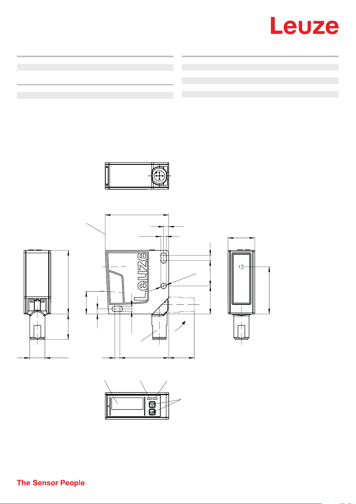
Dimensioned drawings
All dimensions in millimeters
A
50
4,3
Classification
Customs tariff number 90318020
eCl@ss 8.0 27270801
eCl@ss 9.0 27270801
eCl@ss 10.0 27270801
eCl@ss 11.0 27270801
ETIM 5.0 EC001825
ETIM 6.0 EC001825
4
21
50
B
17,7
20
M12x1
A Reference edge for the measurement
B Optical axis
C Device plug M12
E
D
4
4,3
C
4
38,5
FGH
D Receiver
E Transmitter
F Color display
Ø 4,3
20
J
4
20
22
G Yellow LED
H Green LED
J Control buttons
B
37,1
• We reserve the right to make technical changes
• eng • 2020-10-14
3 /8
Page 4
Optical distance sensor • Part no.: 50142241 • ODS9L2.8/LKA.02-450-M12
2
4
Electrical connection
Connection 1
Function Signal IN
Signal OUT
Voltage supply
Type of connection Connector
Thread size M12
Type Male
Material
No. of pins 5 -pin
Encoding A-coded
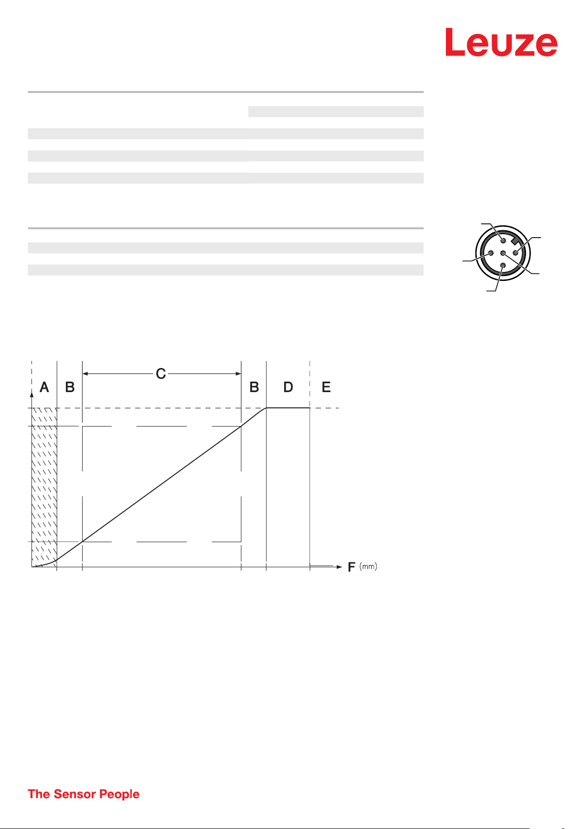
Pin Pin assignment
1 18 ... 30 V DC +
2 multi funct
3 GND
4 IO-Link / OUT 1
5 OUT mA / V
Plastic
1
3
5
Diagrams
Characteristic curve of analog output
A Area not defined
B Linearity not defined
C Measurement range
D Object detected
E No object detected (characteristic curve
behavior adjustable via IO-Link)
F Measurement distance
• We reserve the right to make technical changes
• eng • 2020-10-14
4 /8
Page 5
Optical distance sensor • Part no.: 50142241 • ODS9L2.8/LKA.02-450-M12
6,5 mm
4,5 mm
0,5 mm
y
Diagrams
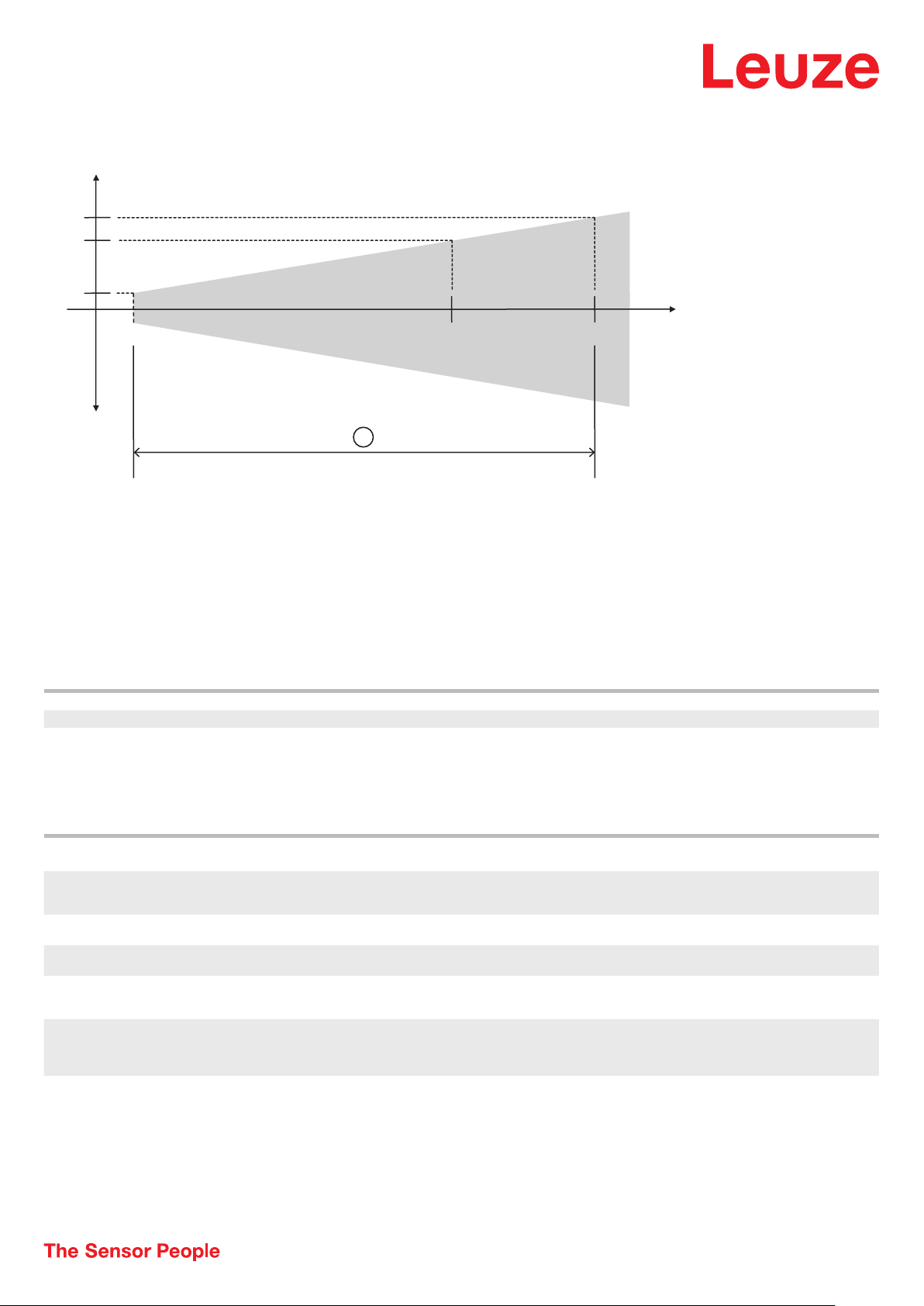
Accuracy of measurement of ODS 9 (measurement value * 0.01 = maximum measurement error):
450 mm 650 mm
x
y
a
x Measurement distance
y Max. measurement error
a 0.5% of measurement value
b 1% of measurement value
Operation and display
LED Display Meaning
1 Green, continuous light Ready
2 Yellow, continuous light Object in the measurement range
Part number code
Part designation: ODS9XX.Y/ZAB-CCC-DDD
ODS9 Operating principle
XX Light source
Y Equipment
Z Switching output/function OUT 1/IN: Pin 4 or black conductor
A Switching output / function OUT 2/IN: pin 2 or white conductor
B Switching output / function OUT 3/IN: Pin 5
Optical distance sensor of the 9 series
L2: laser class 2
L1: laser class 1
8: OLED display and membrane keyboard for configuration
L: IO-Link
A: Analog output
6: push-pull switching output, PNP light switching, NPN dark switching
X: pin not used
6: push-pull switching output, PNP light switching, NPN dark switching
K: Multifunction input (factory setting: deactivation input)
• We reserve the right to make technical changes
• eng • 2020-10-14
5 /8
Page 6
Optical distance sensor • Part no.: 50142241 • ODS9L2.8/LKA.02-450-M12
Part number code
CCC Operating range
DDD Electrical connection
100: operating range 50 … 100 mm
200: operating range 50 … 200 mm
450: operating range 50 … 450 mm
650: operating range 50 … 650 mm
M12: M12 connector
Note
ª A list with all available device types can be found on the Leuze website at
Notes
Observe intended use!
ª This product is not a safety sensor and is not intended as personnel protection.
ª The product may only be put into operation by competent persons.
ª Only use the product in accordance with its intended use.
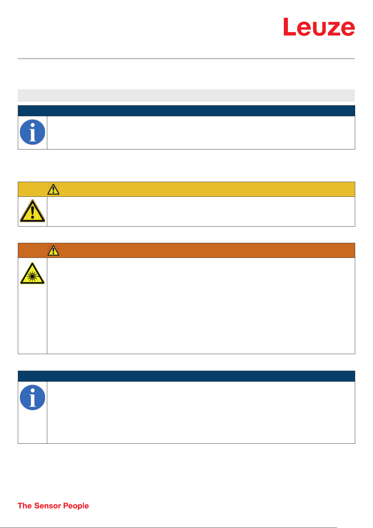
WARNING! LASER RADIATION – CLASS 2 LASER PRODUCT
Do not stare into beam!
The device satisfies the requirements of IEC 60825-1:2007 (EN 60825-1:2007) safety regulations for a product of laser class 2 as well as the
U.S. 21 CFR 1040.10 regulations with deviations corresponding to "Laser Notice No. 50" from June 24, 2007.
ª Never look directly into the laser beam or in the direction of reflected laser beams! If you look into the beam path over a longer time period, there is a risk
of injury to the retina.
ª Do not point the laser beam of the device at persons!
ª Interrupt the laser beam using a non-transparent, non-reflective object if the laser beam is accidentally directed towards a person.
ª When mounting and aligning the device, avoid reflections of the laser beam of
ª CAUTION! Use of controls or adjustments or performance of procedures other than specified herein may result in hazardous light exposure.
ª Observe the applicable statutory and local laser protection regulations.
ª The device must not be tampered with and must not be changed in any way.
There are no user-serviceable parts inside the device.
Repairs must only be performed by
f reflective surfaces!
NOTE
Affix laser information and warning signs!
Laser information and warning signs are affixed to the device. In addition, self-adhesive laser information and warning signs (stick-on labels) are
supplied in several languages.
ª Affix the laser information sheet to the device in the language appropriate for the place of use. When using the device in the US, use the stick-on label
with the "Complies with 21 CFR 1040.10" note.
ª Affix the laser information and warning signs near the device if no signs are attached to the device (e.g. because the device is too small) or if the attached
laser information and warning signs are concealed due to the installation position.
ª Affix the laser information and warning signs so that they are legible without exposing the reader to the laser radiation of the device or other optical
radiation.
• We reserve the right to make technical changes
• eng • 2020-10-14
6 /8
Page 7
Optical distance sensor • Part no.: 50142241 • ODS9L2.8/LKA.02-450-M12
Accessories
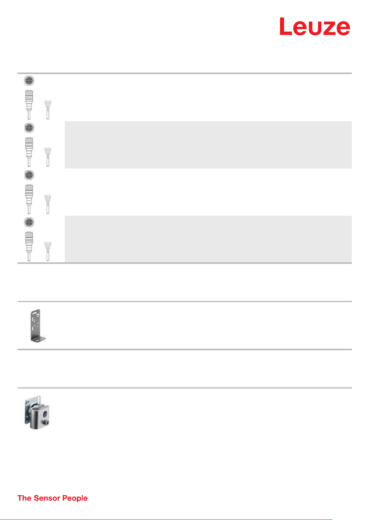
Connection technology - Connection cables
Part no. Designation Article Description
50133855 KD S-M12-5A-V1- 020 Connection cable Connection 1: Connector, M12, Axial, Female, A-coded, 5 -pin
50133856 KD S-M12-5A-V1- 050 Connection cable Connection 1: Connector, M12, Axial, Female, A-coded, 5 -pin
50132077 KD U-M12-5A-V1-
020
50132079 KD U-M12-5A-V1-
050
Connection cable Connection 1: Connector, M12, Axial, Female, A-coded, 5 -pin
Connection cable Connection 1: Connector, M12, Axial, Female, A-coded, 5 -pin
Connection 2: Open end
Shielded: Yes
Cable length: 2,000 mm
Sheathing material: PVC
Connection 2: Open end
Shielded: Yes
Cable length: 5,000 mm
Sheathing material: PVC
Connection 2: Open end
Shielded: No
Cable length: 2,000 mm
Sheathing material: PVC
Connection 2: Open end
Shielded: No
Cable length: 5,000 mm
Sheathing material: PVC
Mounting technology - Mounting brackets
Part no. Designation Article Description
50118543 BT 300M.5 Mounting bracket Design of mounting device: Angle, L-shape
Mounting technology - Rod mounts
Part no. Designation Article Description
50117252 BTU 300M-D12 Mounting system Design of mounting device: Mounting system
Fastening, at system: Through-hole mounting
Mounting bracket, at device: Screw type, Suited for M4 screws
Type of mounting device: Adjustable
Material: Stainless steel
Fastening, at system: For 12 mm rod, Sheet-metal mounting
Mounting bracket, at device: Screw type, Suited for M4 screws
Type of mounting device: Clampable, Adjustable, Turning, 360°
Material: Metal
• We reserve the right to make technical changes
• eng • 2020-10-14
7 /8
Page 8
Optical distance sensor • Part no.: 50142241 • ODS9L2.8/LKA.02-450-M12
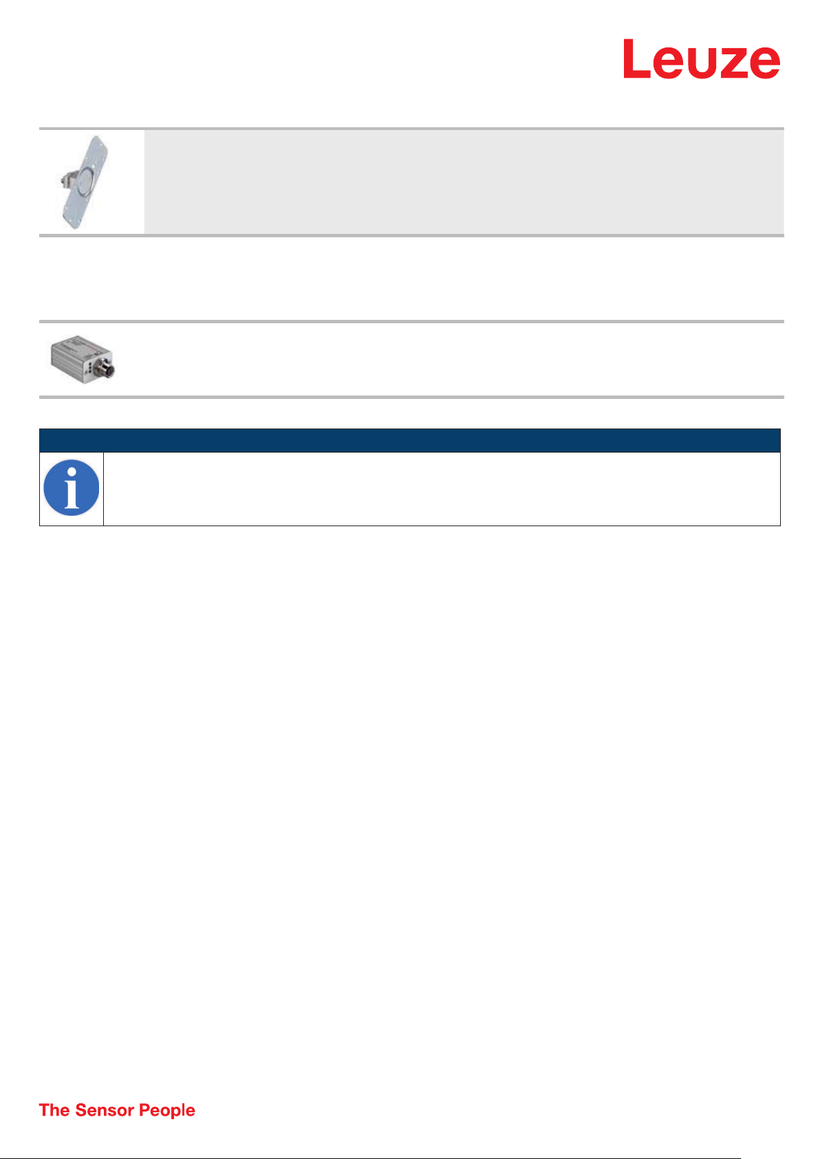
Accessories
Configuration devices
Part no. Designation Article Description
50128380 BTU 460M-D12 Mounting system Design of mounting device: Mounting system
Part no. Designation Article Description
50121098 SET MD12-US2-IL1.1
+ Zub.
Note
ª A list with all available accessories can be found on the Leuze website in the Download tab of the article detailed page.
Fastening, at system: For 12 mm rod
Mounting bracket, at device: Screw type
Type of mounting device: Adjustable, Turning, 360°
Material: Metal
Diagnostics set Interface: USB
Connections: 2 Piece(s)
Degree of protection: IP 20
• We reserve the right to make technical changes
• eng • 2020-10-14
8 /8
 Loading...