

Page 1
Page 2
A Word of Welcome
Thank you and congratulations on your purchase of the Letus35 Extreme! This
manual covers the basic installation and operation of your 35mm adapter
along with additional information on Troubleshooting and Technical Support.
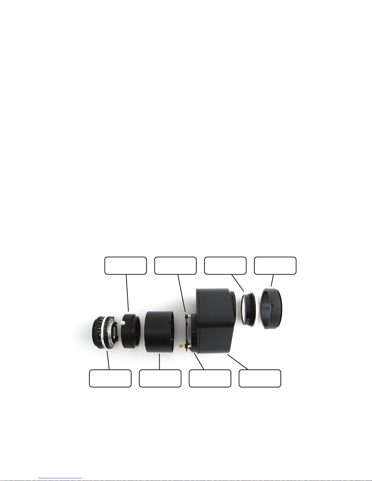
35mm Lens
(user provided)
Front
Tube
Condenser
Lens
Prism
Casing
Interchangeable
Lens Mount
Ground Glass (GG)
& GG Holder
Achromat
Lens
Interchangeble
Connection Ring
Getting to Know the Letus35 Extreme
Below is an image of the dierent components of the Letus35 Extreme for
reference throughout this user guide.
Page 3

Letus35 Extreme User Guide
1
TABLE OF CONTENTS
Understanding The Letus35 ExtremeI. ............. 2
Package Contents:A. .................................. 2
Optional Accessories:B. ................................ 2
Main Features:C. ...................................... 2
Installation and SetupII. .......................... 3
Unpacking: A. ......................................... 3
Connecting The Letus35 Extreme To The Camera:B. ..... 3
Aligning The Adapter:C. ............................... 3
Focusing The Camera Lens To The Ground Glass:D. ...... 4
Attaching The Lens Mount And Lens :E. ................. 5
Powering Up The Letus35 Extreme:F. ................... 5
Happy Shooting:G. . . . . . . . . . . . . . . . . . . . . . . . . . . . . . . . . . . . . 5
Changing The Lens Mounts: III. .................... 5
Measuring Focus: IV. ............................. 6
Adjusting Back Focus: V. .......................... 6
Testing The Focus:A. ................................... 6
Adjusting The Focus: B. ................................ 7
Cleaning The System: VI. .......................... 8
Trouble Shooting And Technical Support:VII. ......10
Warranty:VIII. ...................................10
NotesIX. ........................................12
Page 4
Letus35 Extreme User Guide
2
Understanding The Letus35 ExtremeI.
This section provides information about the Letus35 Extreme, package contents, optional accessories and its main features.
Package Contents:A.
Letus35 Extreme 35mm DOF Adapter »
Lens caps for the Extreme (one for each side »
of the adapter)
Lens mount (which you specied with your »
order)
Your choice of a connection ring (72mm, »
77mm or 82mm). You also can upgrade to
the camera specic optimization kits (e.g.
Sony EX1 kit, Panasonic HVX-200 kit, etc.)
Allen wrench »
Optional Accessories:B.
Support Bracket »
Rod Support System (this system includes the support bracket) »
Rod Extensions »
Custom case »
Additional lens mounts for dierent types of lenses. We oer: »
Canon FD Mount »
M42 Screw Mount »
Nikon Locking Mount »
Canon EF/EOS Locking Mount »
Minolta MD Locking Mount »
Zeiss Contax (C/Y) Mount »
Leica-R Mount »
Pentax-K Mount »
Olympus OM Mount »
PL Mount »
OCT19 Mount »
Camera specic optimization kits (e.g. Sony EX1 kit, Panasonic HVX-200 »
kit, etc.)
Specialized Connection Rings (specically made for certain cameras) »
For the current list of accessories, please visit our website: »
www.letus35.com
Main Features:C.
A half (1/2) Stop of Light Loss »
Page 5
Letus35 Extreme User Guide
3
IOC Prism System to correct the image so it is right side up »
Virtually Quiet: The Vibrating Ground Glass emits nearly no operational »
noise.
Highest Optical Grade Achromatic lens custom-made for the Letus35 »
Extreme 35mm DOF Adapter.
Custom Condenser specially tailored for the Letus35 Extreme 35mm »
DOF Adapter optimizing Image Quality.
New and improved Ground Glass Design: Beautiful Film-Like Bokeh, ac- »
curate color reproduction, absolutely no vignetting and the best Edgeto-Edge Sharpness in the industry.
A sleek On/O indicator with LED. »
Easy alignment »
Fully Enclosed batteries secured by tough magnets for ease of replace- »
ment in the eld.
Extreme Durability, Professional Look: Casing milled from Solid Alumi- »
num and nished in black.
Installation and SetupII.
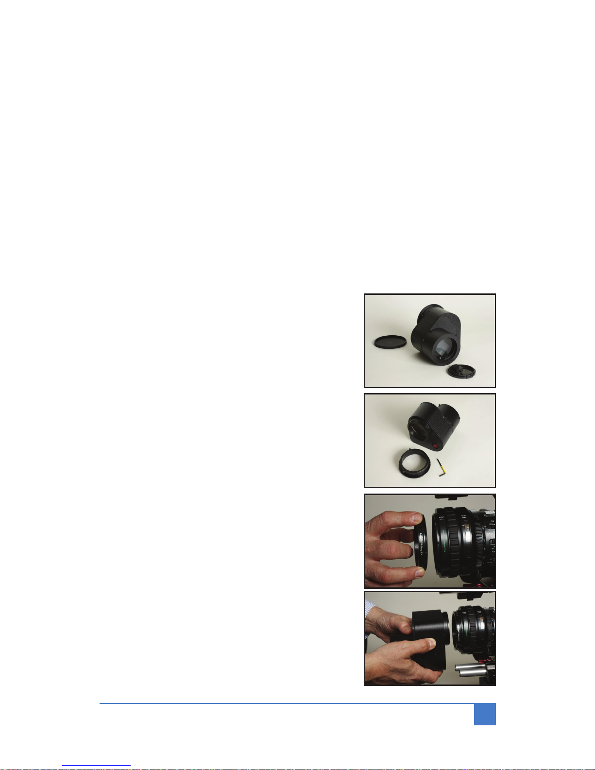
Unpacking: A.
Remove the aluminum rear cap. 1.
Remove the plastic front cap.2.
Connecting The Letus35 Extreme To B.
The Camera:
Using the Allen Wrench Tool included with 1.
your package, loosen the three (3) screws
located on the Back of the Letus35 Extreme
35mm DOF Adapter and carefully remove
the Camera Connection Ring.
Hand tighten the connection ring onto the 2.
camera lter thread (Caution: Do NOT over
tighten the ring to the camera threads as
doing so may cause damage to your cameras threads).
Aligning The Adapter:C.
Turn on your camera and zoom all the way 1.
out.
Fit the adapter into the ring and look at 2.
Page 6
Letus35 Extreme User Guide
4
the LCD screen.
Align the adapter until you have all edges of the Ground Glass (GG) 3.
parallel with the edges of the LCD screen (you may want to zoom in
until the edges of the GG are close to the edges of the LCD screen for
better alignment).
Tighten the 3 allen head screws around 4.
the thread ring once you are happy with
the alignment of the image on the LCD.
Zoom in until the edges of the Ground 5.
Glass (GG) disappear and there are no
signs of vignetting (dark corners or sides).
This will be your outmost zoom level. From
your outmost zoom level you may zoom in
further to achieve a dierent Field of View
(FOV).
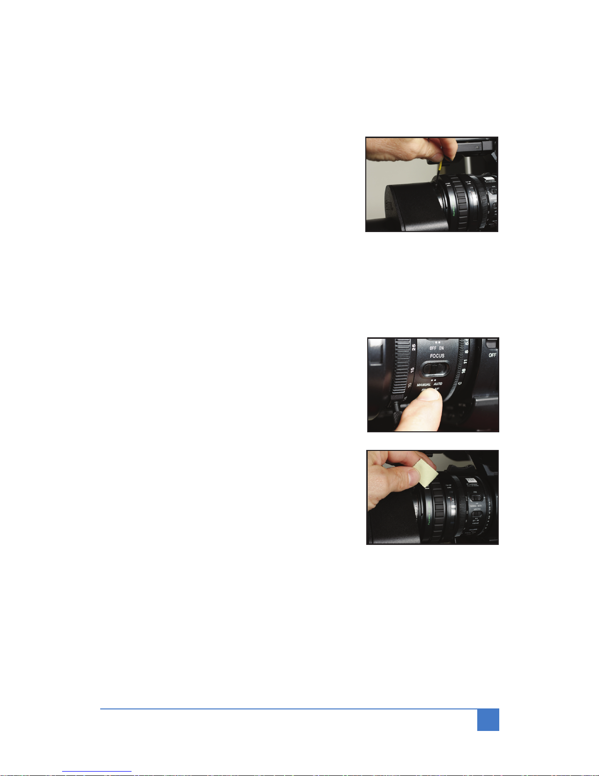
Focusing The Camera Lens To The Ground Glass:D.
Point the adapter (Without a Lens at-1.
tached) toward a well illuminated surface
(white wall, sheet of paper) and by using
your Camera’s IRIS ADJUSMENT or DIAL
until the Ground Glass (GG) Grain Pattern
appears. Then, use your Camera’s FOCUS
ADJUSTMENT or DIAL to focus on the
grain until the pattern is distinct. You may
also use the AUTO FOCUS function of your
camera to focus on the Ground Glass (GG)
Grain Pattern. Once the Grain is in focus,
switch your camera back to MANUAL FOCUS. Your Ground Glass (GG) is now in Focus.
Once you get your camera focused on the 2.
GG properly, lock this focus setting down
(depending on your camera, you may
need to use tape to lock the focus ring in place). You may want to write
this number down for future reference.
Note: For each Field Of View (FOV) chosen you may need to set 3.
your Camera’s Focus once more. It may be desirable to keep a
log of ZOOM and FOCUS settings for each camera being used.
Page 7
Letus35 Extreme User Guide
5
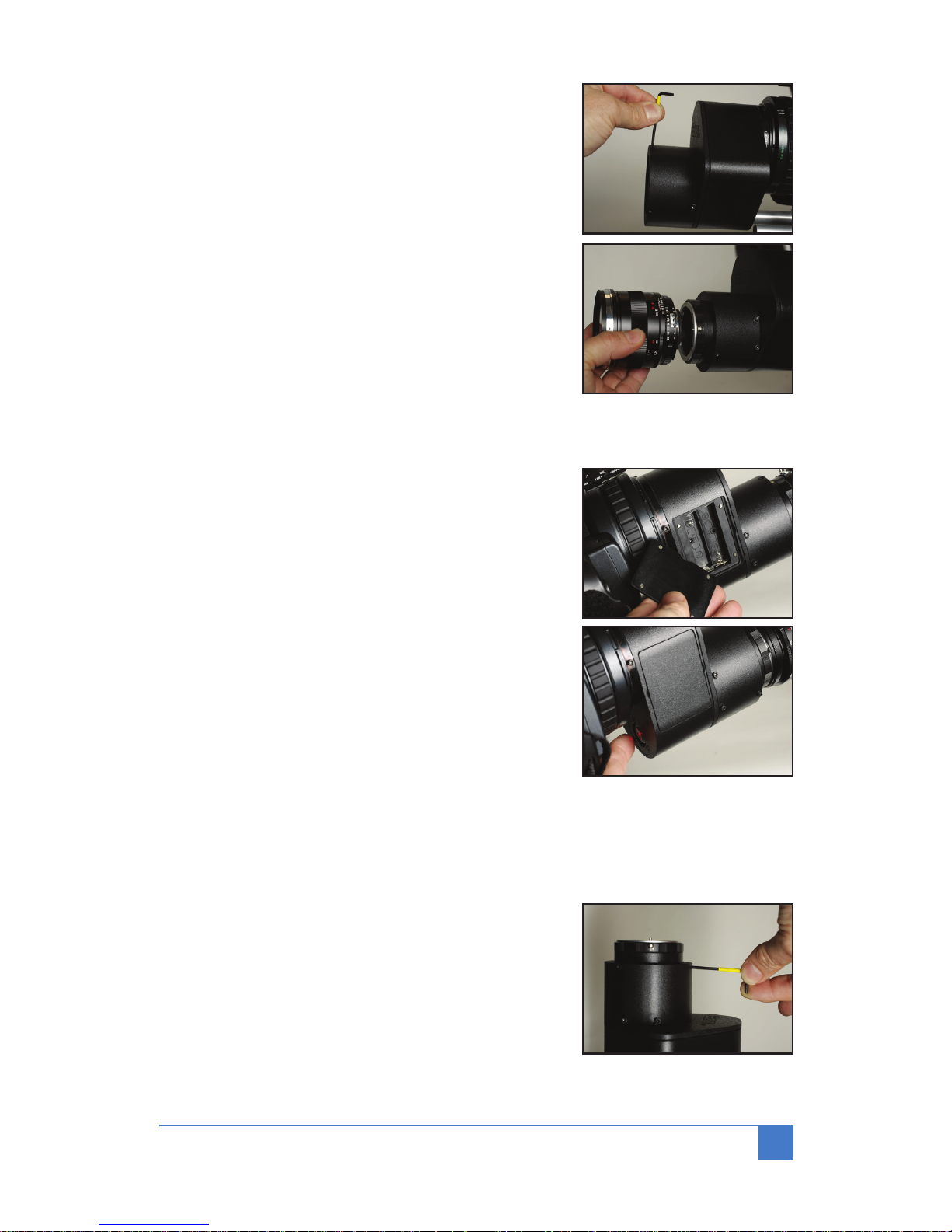
Attaching The Lens Mount And Lens :E.
Using the Allen Wrench Tool included with 1.
your package, loosen the three (3) screws
located at the very front of your Letus35
Extreme 35mm DOF Adapter.
Insert the lens mount into the front tube 2.
of the unit. Make sure to seat the mount
ush against the tube.
Tighten the three (3) set screws to rmly 3.
lock the Lens Mount in place.
Now, attach the appropriate Lens to your 4.
Lens Mount.
Powering Up The Letus35 Extreme:F.
Open the battery cover located on the 1.
side of your Letus35 Extreme 35mm DOF
Adapter.
Insert 2 New AA Batteries.2.
Replace the Battery Cover.3.
Turn on the Letus35 Extreme 35mm DOF 4.
Adapter by pressing the red LED button
on the back. When in operating mode, the
LED will glow Red.
Happy Shooting:G.
You may want to readjust white balance for »
your camera according to taste. Do so by
following normal operations for your camera to manually white balance.
Happy Shooting! »
Changing The Lens Mounts: III.
The Letus35 Extreme 35mm DOF adapter will allow you to use dierent lens types for your project. Each lens type will require a unique lens
mount. Here are the steps to swap in/out the lens
mounts:
Page 8
Letus35 Extreme User Guide
6
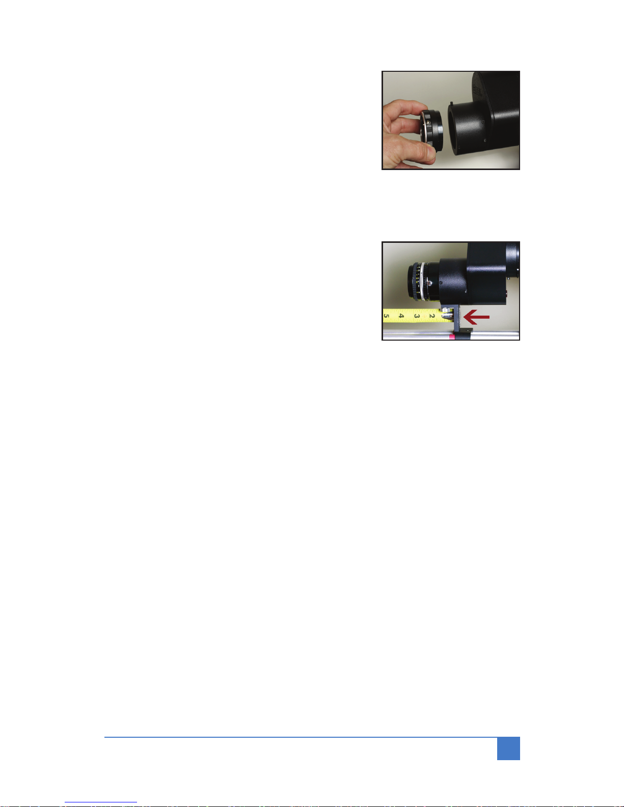
Using the Allen Wrench tool included with 1.
your package, loosen the three (3) screws
located at the very front of your Letus35
Extreme 35mm DOF Adapter.
Remove the current lens mount.2.
Insert the optional lens mount into the 3.
front tube of the unit. Make sure to seat
the mount ush against the tube.
Tighten the three (3) set screws to rmly lock the Lens Mount in place.4.
Measuring Focus: IV.
The Film Plane for the Letus35 Extreme 35mm
DOF Adapter is 28.2mm from the front of the tube
toward the main body. If you have the optional
support bracket, the back of this bracket is the
Film Plane; attach your tape measure to this section on the adapter.
Adjusting Back Focus: V.
The back focus is set at the factory, so it should not need adjusting. In the event
that back focus for your Letus35 Extreme 35mm DOF Adapter needs to be adjusted, refer to this section. Generally, if your lens achieves Innity Focus, your
shooting situations will not be aected. Some operators may also want to further adjust for accurate barrel markings on Still Camera Lenses. Follow these
steps:
Testing The Focus:A.
Setup your camera with the Letus35 Extreme 35mm DOF Adapter us-1.
ing the preceding instructions, and attach a 50mm lens. (Any lens will
do, we’ve used a 50mm Lens because it is the easiest to use and widely
available amongst users).
Place a Siemens Star (available in the inside back cover of this manual) 2.
in front of the lens at a predetermined distance. For this example we
will use a four (4) foot distance from Film Plane to the Siemens Star. To
determine the distance of the star you will need to measure from the
Film Plane to the star. (See: IV. Measuring Focus).
Using the lens, focus on the Siemens Star. The focal markings should 3.
correspond to your focal distance appropriately. Example: At four (4)
feet the Siemens Star should be the focus point of your image or in
Page 9
Letus35 Extreme User Guide
7
focus. If it is not, you may need to adjust back focus.
Adjusting The Focus: B.
There are two (2) cases where you may want to adjust the back focus:
Case 1: If your lens can achieve innity focus at less than the innity marking,
subsequently, the barrel markings are slightly o. This is how to x it:
Gently loosen the three (3) set screws holding the lens mount.1.
Remove the lens mount and lens from the tube.2.
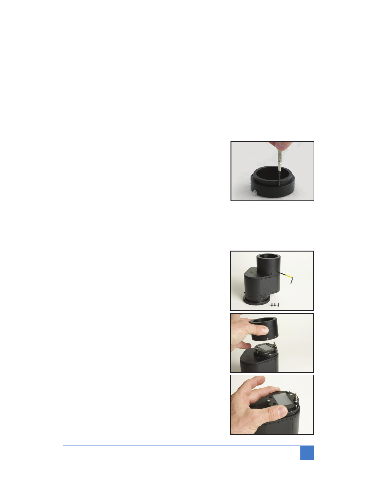
Located on the back of the lens mount 3.
are three (3) small screws. Carefully, one
at a time, loosen each one a small amount.
Each screw should be loosened an even
amount. About 0.2mm may do.
Re-insert the lens mount and attached 4.
lens into the tube.
Tighten the three (3) set screws.5.
Re-peat the6. Testing The Focus step,
checking your focal marks for accuracy.
If yes, you are done. If not, repeat this step until back focus is correct-7.
ed.
Case 2: If you cannot achieve innity focus at all,
follow this method:
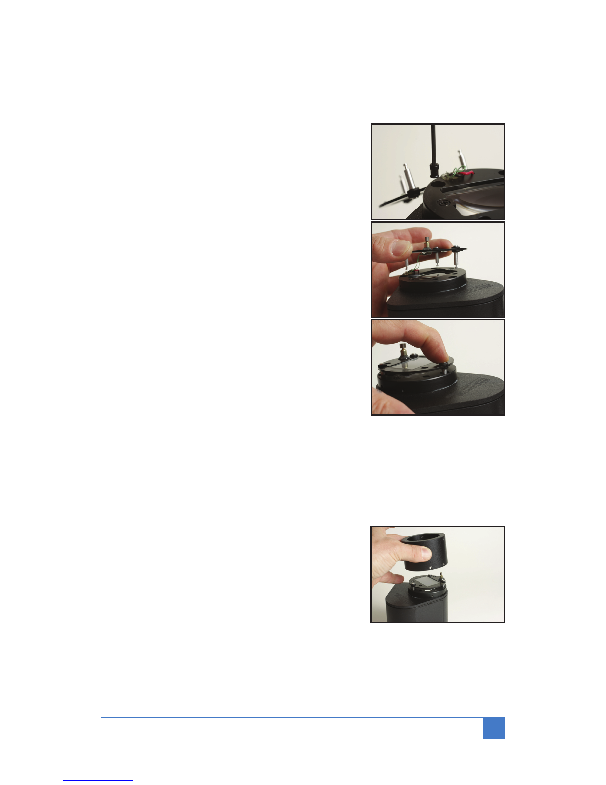
Remove the four (4) Allen Screws holding 1.
the front tube to the body of the adapter
VERY carefully and VERY gently remove the 2.
tube from the adapter. At this point you
should see the Ground Glass (GG) which is
mounted on three (3) Aluminum Posts.
VERY gently, and evenly, pull the three (3) 3.
Aluminum Posts outward away from the
Body about 0.2mm one at a time.
Replace the front tube.4.
Repeat the 5. Testing The Focus step.
If you do get innity focus, then see if the 6.
other markings are correct. If the markings
are also correct, you are done. If you can
get innity focus but the marking is not
correct, go to the steps in Case 1 to x it.
Page 10
Letus35 Extreme User Guide
8
If you are still unable to achieve Innity Focus repeat these steps. Once 7.
you are able to achieve Innity Focus, next, repeat 1. Checking The
Focus for accuracy of your lens Focal Marks. If the lens Focal Marks are
inaccurate, follow Case 1 adjustment steps.
NOTES: Be VERY careful pulling the Ground Glass
(GG) posts away from the adapter body. Avoid
touching the Ground Glass (GG) with bare ngers
as it will transfer oils to the Film Plane and may
cause unwanted eects in your image. If, by accident, you happen to pull one of the posts from
its socket DO NOT PANIC! Remove the Rubber
Boot from the post VERY carefully, then, with a
toothpick or the allen wrench you received with
your adapter, gently tuck the Rubber Boot back
into the mounting hole. Then, carefully re-insert
the Aluminum Post into the rubber boot. DO NOT
attempt to force the Aluminum Post with Rubber
Boot attached into the mounting hole for risk of
damaging the boot and Ground Glass (GG) mounting system. Take your time and be very careful.
Cleaning The System: VI.
We try our best to ship each unit free of dust in the
Optical Path. However, the Magic of Dust Particles
is always surprising. In which case you may need to clean the optical path, refer
to the steps listed below: NOTE: If the dust moves when the unit is operating
it will more than likely be located on the Ground Glass (GG) and you will only
need to perform steps 1 – 3.
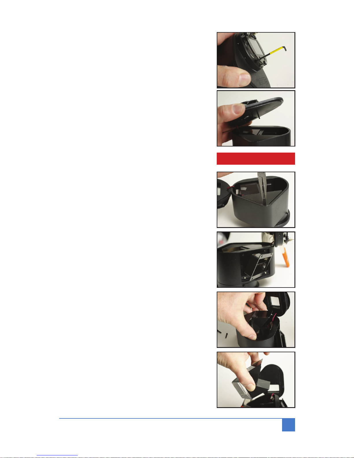
Open the front tube of the Letus35 Ex-1.
treme 35mm DOF Adapter by removing
the four (4) screws and VERY carefully remove the tube. You will see the Ground
Glass (GG).
Clean the ground glass if you nd the dust 2.
there. Only go on to next step if the speck
is stationary when the ground glass is rotating, if it is clean, put the tube back on. If not, continue to step 3.
Clean the top surface of the condenser (the glass right below the 3.
ground glass). If the speck goes away, you are done cleaning, put the
tube back on. If not, continue to step 4.
Page 11
Letus35 Extreme User Guide
9
Through the 2 holes on the ground glass 4.
holder, unscrew the 2 Allen screws holding the enclosure cap to the body of the
adapter. Use a at object to pry o the enclosure cap from the body of the adapter.
Clean the other side of the condenser.5.
Clean the top surface of the prism.6.
Put the enclosure cap back on and use the 7.
2 Allen screws to secure it in place again.
Do not over tighten them.
Put the front tube back on.8.
NOTE: Dust will not matter beyond this point,
unless it is a stain. To remove a stain, please send it
back to the factory for repair. The warranty WILL
BE VOIDED if you perform step 9 and beyond.
Pull the black rubber wedge at the roof of 9.
the prism out with a pair of narrow pliers.
Take the battery compartment o and 10.
gently pull it out. Remember, the wires are
still attached to the battery compartment.
Lift the prism up by using the index nger 11.
and the thumb.
Clean the prism with lens cleaning solu-12.
tion and put it back.
Put the rubber wedge back.13.
Put the enclosure cap back and use the 2 14.
allen screws to secure it in place. Do not
over tighten them.
Put the front tube back on.15.
CAUTION
Page 12

Letus35 Extreme User Guide
10
Trouble Shooting And Technical Support:VII.
In the case you encounter circumstances that are not described in this user
guide, please contact us at 1-877-77-LETUS (1-877-775-3887). We are open
Monday through Friday from 9AM to 5PM Pacic time. If you bought our
products through one of our authorized dealers and the adapter came not in
the optimal shape, PLEASE CALL US rst before returning to the dealer.
Warranty:VIII.
Letus Corporation warrants that its products, when installed and used in accordance with the user
guide, will perform in accordance with specications current as of the date of shipment, and will
be free from defects in material and workmanship for a period of one (1) year on new products
and ninety (90) days on repaired products and/or components. Excluded from this Warranty is any
physical damage caused by abuse, accident, or improper operation, and any lack of performance
attributable to such abuse, accident, or improper operation, as determined by Letus Corporation.
Letus Corporation shall not be liable for any incidental or consequential damages, including loss of
production time or money, regardless whether the product functioned properly or improperly for
any reason, including those for which Letus Corporation bears liability.
The one (1) year warranty period for new product shall be the one (1) year period beginning with
the date of the products receipt by the customer. The one (1) year warranty is non-transferable and
only applies to the original purchaser.
For repaired or replaced products, the repaired or replaced component is warranted to be free of
material and workmanship defects, and to perform its function in accord with Letus Corporation
specications for a period of thirty (30) days from its date of shipment, or its original remaining
Warranty period, whichever is the latter. All claims under this Warranty shall be immediately submitted to Letus Corporation in writing and are subject to conrmation.
Should Letus Corporation deem it appropriate to return the accessory or a component to a Letus
Corporation-designated location, it will issue the buyer a Return Material Authorization Number
(RMA number), which must accompany all returns. The returned accessory or component shall
remain the property of the buyer who shall ship it freight prepaid to the designated Letus Corporation location with the RMA number clearly displayed on the packaging exterior and all paperwork.
Letus Corporation, upon receipt and subsequent conrmation of a warranty defect, at its sole option, shall repair or replace the accessory or its component and return it freight prepaid to the
Buyer within twenty (20) days from date of its receipt. At Letus Corporation’s discretion, Buyer may
be responsible for shipping costs. Any upgraded return shipping method request made by the
Buyer shall be borne by the Buyer.
This Warranty is made in lieu of all other warranties whatsoever, express, implied and statutory. The
acceptance of any order with Letus Corporation is expressly made subject to the Buyer’s agreement to this Warranty.
Return equipment items - including but not limited to the Letus35 Extreme, Letus35 Mini, Letus35
Ultimate, accessories, rods, rod support systems, lens mounts, and attire: All major equipment sales
carry a 14 day return policy (less a 20% restocking fee) with the exception of defective merchandise. Defective merchandise is eligible for return within 14 days. If the item is found to be defective,
Page 13

Letus35 Extreme User Guide
11
the customer will receive a direct exchange, suitable replacement (if item has become discontinued or unavailable), a repair, or in-house credit at the discretion of Letus Corporation.
Please note that the following items are not refundable for any reason: Shipping and handling
charges, rush processing charges, taxes, duty, processing charges, or other fees imposed on an
order.
A minimum restocking fee of 20% will be imposed on all non-defective merchandise. There is no
restocking fee on the return of defective merchandise. Letus Corporation reserves the right to
charge additional restocking fees for merchandise returned in less than acceptable condition.
A Return Merchandise Authorization (RMA) number must be obtained from Letus Corporation
prior to returning any merchandise. Any product returned to Letus Corporation without an RMA
number will be returned to the customer at the customer’s expense and no credit will be issued.
RMA numbers are valid for a period of 30 days only. Merchandise received beyond the 30 day period will not be credited and will only be returned to the customer at the customer’s expense.
All returns must be shipped freight prepaid with the RMA number displayed on the outside of the
shipping box along with the number of boxes being shipped back (i.e. 1 of 3, 2 of 3, etc.). Letus Corporation WILL NOT ISSUE CALL TAGS FOR ANY REASON WHATSOEVER. For your own protection, we
suggest shipping all returns fully insured and via traceable carrier. We will not be held responsible
for items damaged or lost in transit to us.
All returns will be credited based on the price paid on the invoice, or current selling price, whichever is lower, less any restocking fees.
All returns must include a copy of the Letus Corporation invoice, and a letter explaining the reason
for return.
All non-defective returns must be in new, re-sellable condition with all original unmarked packaging, accessories, manuals and unmarked warranty cards. Items showing signs of use will not be
accepted for credit.
Letus Corporation reserves the right to have defective merchandise exchanged for replacement
or repair.
Please allow up to 14 business days for Letus Corporation to process and credit a return. Actual
time for credit to appear on bank card will vary from bank to bank.
Page 14

Letus35 Extreme User Guide
12
NotesIX.
Page 15

Focusing Aid
Page 16

Copyright © 2008 Letus Corporation
Letus35 Extreme User Guide version 1.0.0
 Loading...