

Page 1
PARTS LIST
QTY. DESCRIPTION
A 1 HORIZONTAL PIPE
B 1 VERTICAL PIPE
C 1 BOLT
D 2 BOLT
E 6 FLAT WASHER
F 3 NUT
G 2 U-BOLT
H 4 WASHER
G
H
J
Accessory Option for GearCage FP4 & FP6 Model Hitch Racks
QTY. DESCRIPTION
J 4 NUT
K 1 ANGLE BRACKET
L 1 V-BRACE
M 1 NO-MOTION PIN
N 1 LOCK WASKER
P 1 1/2 FLAT WASHER
Q 1 LARGE COTTER PIN
R 4 WHEEL CRADLES
S 8 RUBBER STRAPS
T 4 SMALL COTTER PIN
U 2 WINGS
V 4 WHEEL STOPS
W 2 WIRE LOCK PINS
Rack-IT™
Part No. H01199
REQUIRED TOOLS:
10mm SOCKET WRENCH, 13mm SOCKET WRENCH,
13mm WRENCH, 4mm ALLEN WRENCH
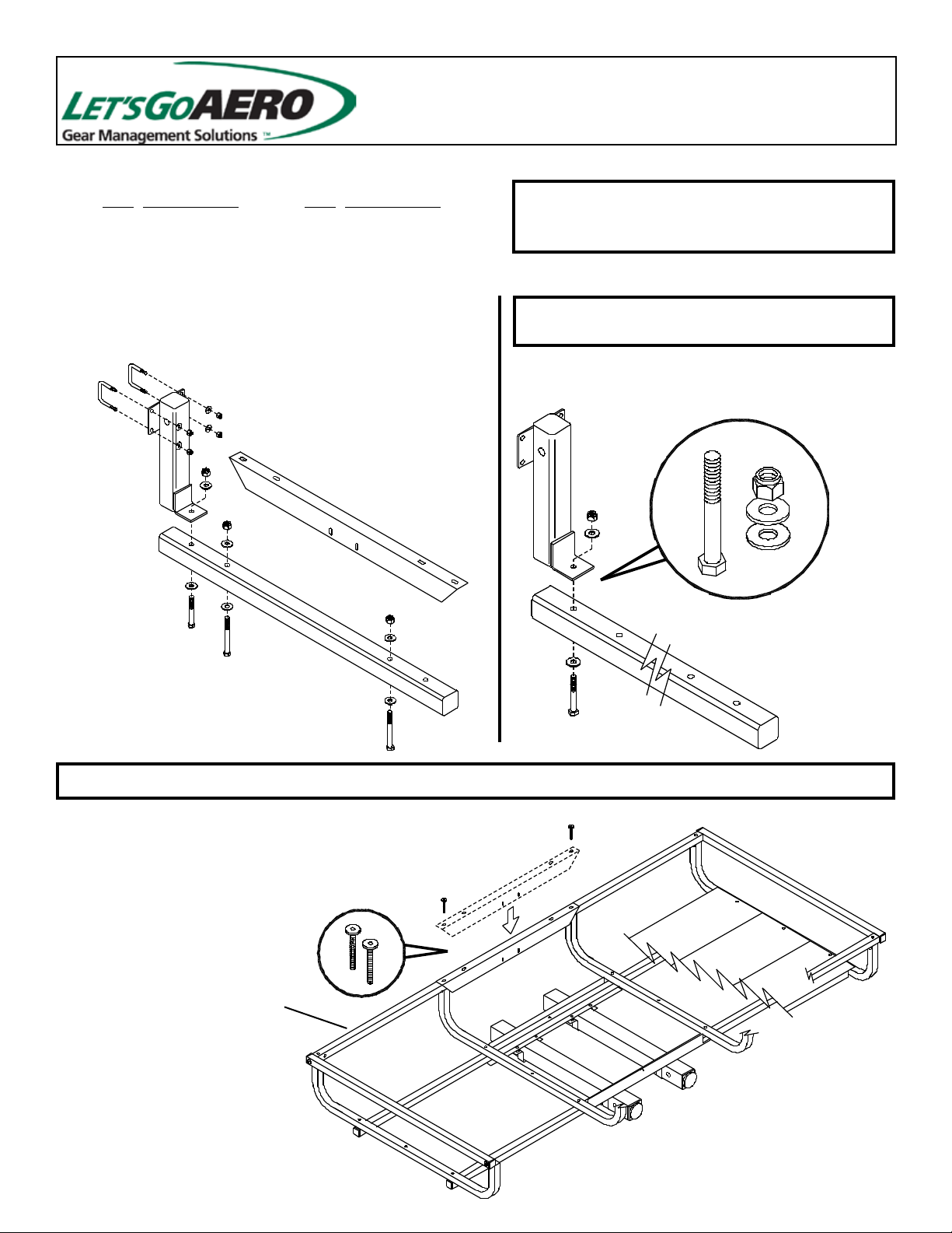
STEP 1
TOOLS: 13mm WRENCH and 13mm SOCKET WRENCH
Attach vertical pipe [B] to horizontal pipe [A] as shown.
Tighten Securely. [DETAIL 1]
B
B
K
F
E
C
D
STEP 2
Attach angel bracket [K] as shown. Do so by removing
the two joint connector bolts from the side tube of the
GearCage hitch carrier (GearCage not included), positioning the angel bracket [K] as shown, then reusing the
joint connector bolts.
[DETAIL 2]
TOOLS: 4mm ALLEN WRENCH
JOINT
CONNECTOR
BOLTS
A
[DETAIL 1]
K
C
F
E
E
A
SIDE TUBE
[DETAIL 2]
RACKIT-012317
Page 2
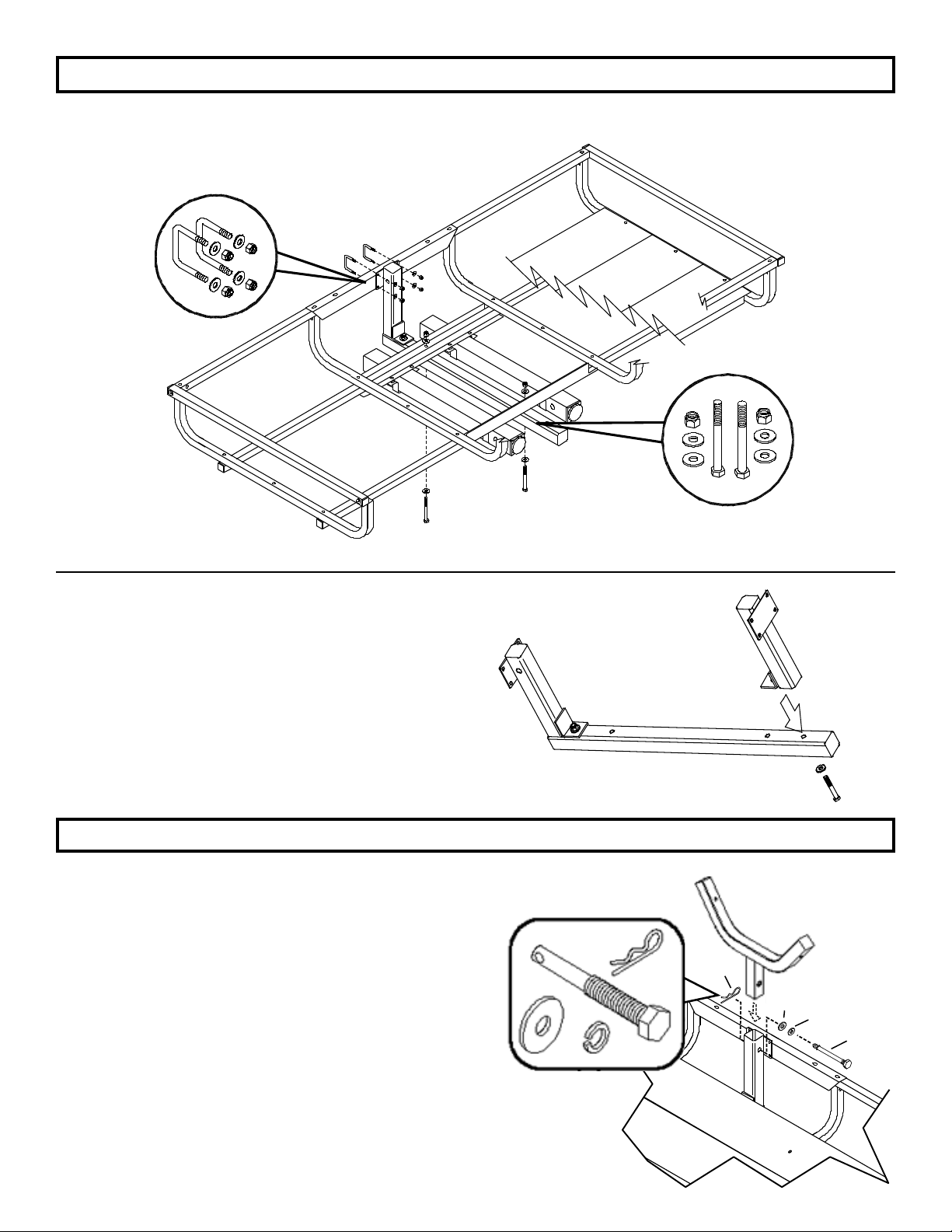
STEP 3
Use the remaining hardware to attach the horizontal pipe/vertical pipe assembly [A,B] as shown. [DETAIL 3]
TOOLS: 10mm SOCKET WRENCH, 13mm SOCKET WRENCH, 13mm WRENCH
JOINT
CONNECTOR
BOLTS
SIDE TUBE
AB
[DETAIL 3]
TIP: Note that the Rack-It can be combined with a
second Rack-It to adapt your GearCage cargo carrier
to hold even more bikes. If you add a second RackIt kit, you will end up with one extra “throw-away”
horizontal pipe. You will attach the vertical pipe from
the second Rack-It kit to the open end of the existing
horizontal pipe. [DETAIL 4]
STEP 4
Attach V-Brace [A] to Vertical Pipe [B] using No-Motion Pin
[M] and Washers [P,N ]. FOR SAFETY insert Large Cotter
Pin [Q] through hole at the end of [M] after tightening [M]
securely.
[DETAIL 5]
REQUIRED TOOLS: 9/16” SOCKET WRENCH, 3/4” SOCKET WRENCH.
P
N
Q
VERTICAL
[DETAIL 4]
M
SECOND
PIPE
L
Q
P
N
M
[DETAIL 5]
Page 3
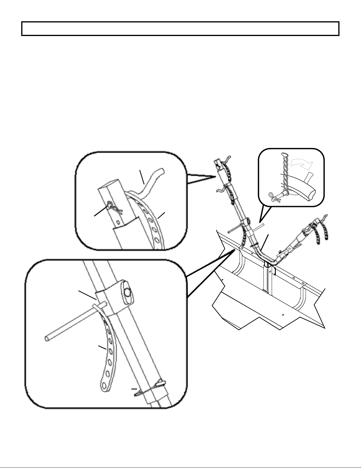
STEP 5
Install eight Rubber Straps [S], one onto each Cradle [R] and one onto each Wheel Stop [V] with the HammerHead end of the Rubber
Straps Facing away from the Cradle [R].
Attach four Cradles [R] two to each Wing [U] securing with Small Cotter Pins [T]. [DETAIL 6]
Slide Two Wheel Stops [V] onto each Wing [U]. With each facing in the same direction at the Wheel Cradles [R] located above.
[DETAIL 7]
NOTE: Pad position is not xed. You can slide pads on Wing [U] to expose additional holes. Where you choose to attach each Cradle
assembly will depend on the size and shape of the bicycle(s) to be transported. Several hole positions are provided for Cradles [R].
Pads and Wheel Stops [V] slide along the length of Wings [U].
Attach wings [U] to base [L] using two Wire Lock Pins [W]. [DETAIL 7 & 8]
NOTE: Wire Lock Pins [W] should point in opposite directions.
V
[DETAIL 6]
T
R
S
L
U
[DETAIL 8]
[DETAIL 7]
S
U
W
Page 4
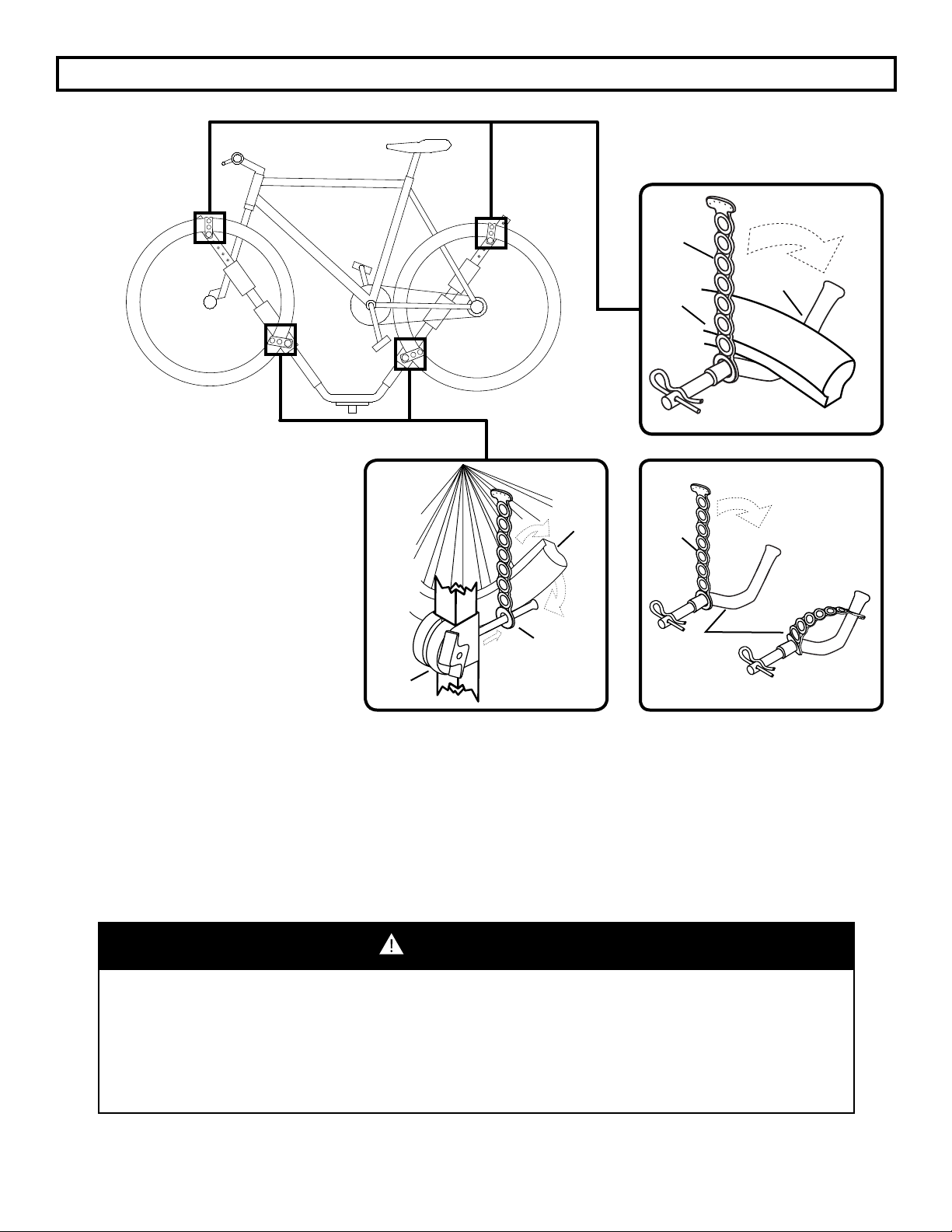
ATTACHMENT OF BICYCLES
RUBBER
STRAP
DETAIL 9
BICYCLE
WHEEL
CRADLE
One Cradle assembly should be attached
to each side of each Wing [U] as
instructed in STEP 5.
Lift the bicycle and hang it on the Rack-IT
with the drive-train of the bicycle facing
BICYCLE
WHEEL
RUBBER
STRAP
away from the rack for a closer t. Secure
each wheel to Cradles [R] as shown
RUBBER
STRAP
[DETAILS 9]. Loosen and adjust Wheel
Stops [V] until they are ush and resting
against the bottom of the tire [DETAIL 10].
RUBBER
STRAP
CRADLE
[Removing the Wing [U] and rearranging
the Wheel Stops [V] and Wheel Cradles
[R] may be necessary depending on your
WHEEL
STOP
DETAIL 10 DETAIL 11
bicycles size and style.] Once the Cradles
[R] and Wheel Stops [V] have been t to
size, stretch the adjustable Rubber Straps
[S] over the tire and reconnect to the
hole position the is one hole tighter than
necessary with the wheel sandwiched at the end of the Pegs of the away from the Wing [U] [DETAIL 11].
Note: Bike Tire can be adjusted in and out to remove contact with the Rack-IT. The pads should be positioned as
necessary for added protection to the nish of the bicycle.
To attach a second bicycle follow the same procedure using the two remaining cradles [R] and wheel stops [V] attached
to the back side of the Wings [U]. Position the second bicycle with the handlebars towards the back of the rst bicycle.
WARNING:
IMPORTANT FOR SAFETY! AFTER ATTACHING BICYCLE(S),
BUT BEFORE DRIVING THE VEHICLE, DOUBLE CHECK ALL
POINTS OF ATTACHMENT TO BE SURE THAT THEY ARE
TIGHT AND SECURE!
Page 5

USAGE GUIDELINES
The Rack-IT bicycle carrier’s maximum load weight is 80lbs. Do not exceed this carrying capacity. Do not exceed the
receiver hitch manufacturer’s tongue weight rating.
Do not use this rack and accessories for purposes other than those for which they were designed. Failure to follow the
guidelines of the product’s instructions will void the warranty.
To learn more about our line of bicycle carriers for vehicle, home storage, and accessory options for carrying fat bikes,
snowboards/skis, and more, be sure to visit our website: www.LetsGoAero.com
To register your product, visit the Let’s Go Aero website at www.LetsGoAero.com
ONE YEAR LIMITED WARRANTY
Let’s Go Aero warrants this product to be free from defect in material and workmanship for one year (retain your sales receipt for your records). Any product or part thereof found to be defective within that period will be replaced without charge
provided that: (1) the product was not misused; (2) no alterations or modications were made; (3) its failure was not a
result of normal wear expected in the use of the product; (4) the product or part is delivered, freight prepaid, to Let’s Go
Aero. Manufacturers only obligation shall be to replace such products or parts proved to be defective. A Return Merchandise Authorization is required prior to return. Please contact Let’s Go Aero toll-free, at 877-464-2376 or 719-630-3800, or
via email to [email protected] to get an RMA number.This warranty terminates if a purchaser transfers the product
to any other person. No warranty is given for LGA products purchased outside of the United States and Canada.
For More Information & Accessories
Visit our Website - www.LetsGoAero.com
Contact Us at 877-474-2376 or 719-630-3800 | Email [email protected]
U.S. Patent No: D717716; D7177177; D684917; 8,899.456; D722289; Patents Pending
Copyright © 2017 Lets Go Aero Inc.
 Loading...