

Page 1
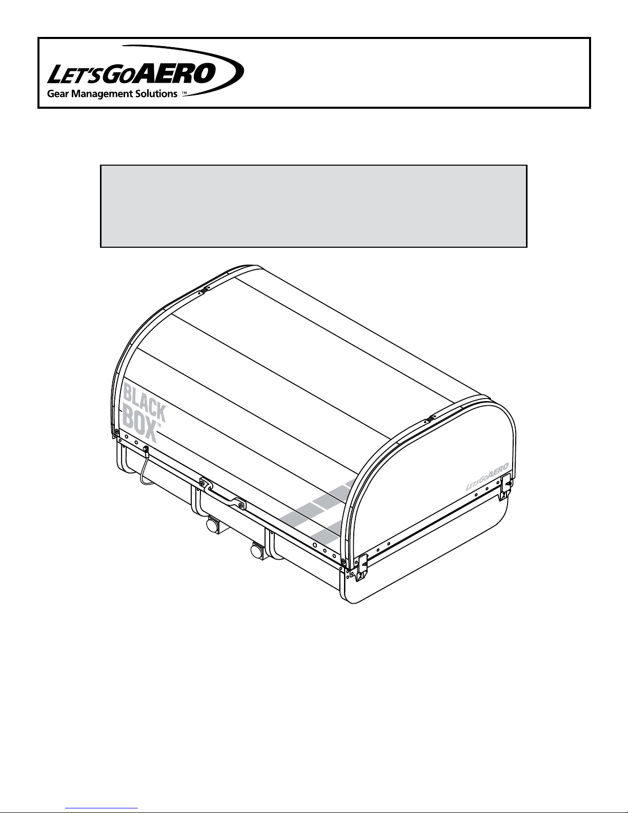
BLACK BOX
Slide-Out Enclosed Cargo Carrier System
Set Item Product
PRODUCT MANUAL
Installation & Safe Use Operation Highlights
Fits 2” size receiver hitches.
Rated for 300 lbs of cargo payload. 160 lbs empty weight.
Class II minimum tow rating required; Class III recommended.
BlACK BOX SYSTEM - ASSEMBLY, INSTALLATION, AND OPERATION INSTRUCTIONS:
Description Page
FlatPipe™ Spine Assembly & Installation on Hitch........................................... 2
Safe Use & Operation ........................................................................................ 3
Rack Parts & Assembly ...................................................................................... 4
AerFoil Lid Parts & Assembly ............................................................................. 11
Warranty & Registration ..................................................................................... 14
For More Information & Accessories, Visit our Website - www.LetsGoAero.com
For Technical Support & Product Questions Contact Us at 877-464-2376 or 719- 630-3800
BBOXManual-042117Rev
Email: [email protected]
PAGE 1 OF 14
Page 2
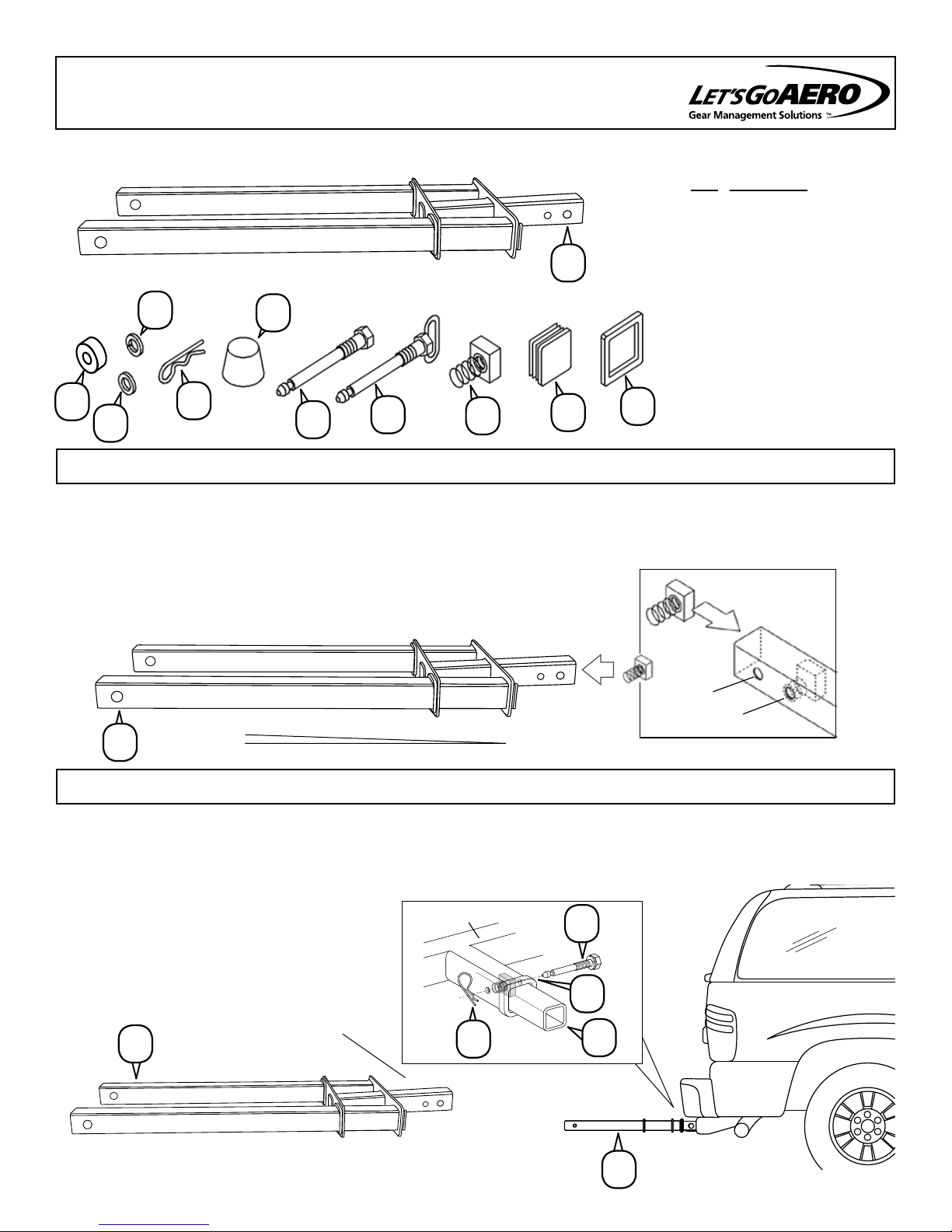
FLATPIPE™ SPINE ASSEMBLY AND INSTALLATION
A
F
E
B
L
J
C
D
G
H
Qty. Description
A 1 FlatPipe™ Spine
B 2 Retainer Clip
C 1 5/8” Silent Hitch Pin
D 1 5/8” Silent Hitch Pin®
(hand-tighten version)
E 1 5/8” Lock Washer
F 1 5/8” Plastic Bushing
G 2 5/8” Spring Nut
H 2 End Cap, 2” Square
J 1 Wax
K 2 Rubber Bumper
L 1 5/8” Flat Washer
K
®
STEP 1 Install two spring nuts [G] as shown.
The Spine shank end contains two mounting holes. The ideal hole to use is the second hole in from the end. If the
shank bottoms out inside the receiver hitch, or if you need maximum clearance for a tailgate, use the first hole in
from the end.
NOTE: For proper cargo carrier balance, there is a 3° pitch on the Flat Pipe. Be
sure when installing your shank into the receiver hitch that the shank is right side
up and that the 3° faces upward.
Shank End
A
STEP 2
Slide the shank end of the Spine [A] into the receiver hitch aligning the mounting hole with the hole in the receiver hitch. Attach with Silent Hitch Pin and a 5/8” Lock Washer [C,E] by threading the Pin into the Spring Nut
[G]. Tighten (30 ft.lbs. torque)and attach Pin Clip [B].
REQUIRED TOOL: 7/8” WRENCH
3° Pitch
FIRST
SECOND
INSERT INTO VEHICLE
HITCH RECEIVER
A
Hitch Receiver
B
Shank End
PAGE 2 OF 14
C
E
A
A
Page 3
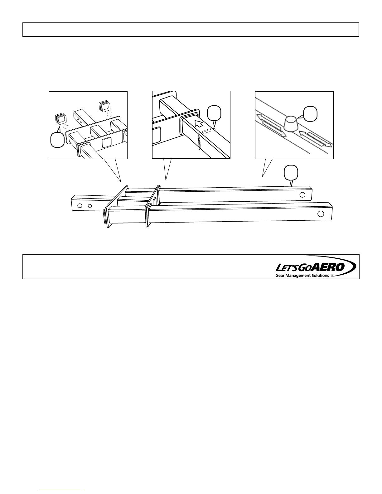
STEP 3
Apply Wax [J] by rubbing the Wax block on all four sides of both tubes. Install two rubber bumpers [K] (one
onto each fixed tube). The remaining hand-tighten Silent Hitch Pin, Bushing and Retainer Clip [D,F,G] will be
used to secure the Black Box Rack to the FlatPipe Spine in a later step.
End Caps [Factory Installed] Rubber Bumpers Wax
K
J
H
A
SAFE USE OPERATION
Be sure to follow these guidelines to prevent possible hazards from misuse.
Vehicle and Hitch Receiver Compliance
This Cargo Carrier fits 2" size hitch receivers and is rated for a Class II tow capability or higher. Before using this
product, consult your vehicle and hitch receiver owner manual(s) for details on your tow and tongue weight parameters.
Be sure that they are compatible with Black Box’s weight specifications.
Tongue Weight Compliance
The Black Box and its cargo create a combined weight that creates direct downward pressure on the hitch receiver’s
tongue. This downward pressure is the tongue weight. Tongue weight is one of the two critical weight rating factors of
your tow rating’s classification. Never exceed your vehicle and hitch receiver’s tongue weight specification.
Black Box Weight and Load Parameters
The Black Box weights 160 lbs empty. To determine your available load weight in accordance with your vehicle
and hitch receiver’s tongue weight rating, subtract Black Box’s weight from your identified tongue weight rating. The
difference represents your vehicle and hitch receiver’s available load weight. The Black Box is rated for up to 300 lbs of
cargo payload weight. Position heaviest cargo in the center of the carrier and lighter cargo to the outside perimeter
About Slide Out & Clearance Adjustment Of Carrier
To telescope the Black Box, remove the Hand Tighten Silent Hitch Pin® from the slide out pin hole. Verify that the
Safety Cable is secured and then slide the frame to the rear. For added clearance, adjust the position of the Hat
Brackets along the Frame’s Female Slide Tubes. Be sure to adhere to NO USE AREA distance of 3.5 inches rearward
from Spine’s vertical plate along the frame tubes.
TIP: Secure your gear during transit, contents may shift causing damage to gear and/or cargo carrier. It is user
responsibility to properly secure cargo. Optional tie down items are available at Let’s Go Aero for purchase.
PAGE 3 OF 14
Page 4
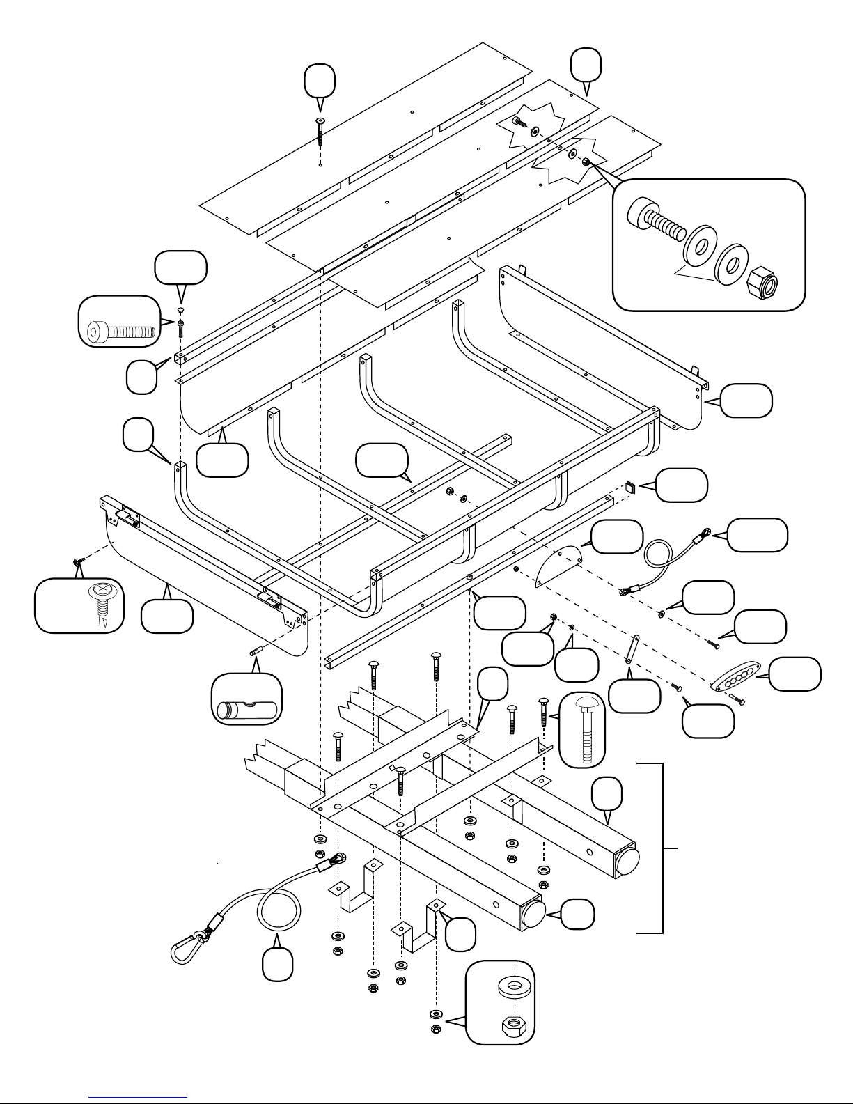
RACK PARTS LIST & ASSEMBLY OVERVIEW
Tools Needed:
9/16" Wrench and Socket
7/16" Wrench and Socket
5/32” Hex Key
3/16” Hex Key
Center Punch
Drill and Drill Bits
TWINTUBE FRAME MOUNT
QTY. DESCRIPTION
2
M
N
O
P
Q
R
S
T
FEMALE TUBES
2
FRAME ANGLES
4
HAT BRACKETS
8
5/16 CARRIAGE BOLTS
8
5/16 WASHERS
8
5/16 NUTS
1
SAFETY CABLE WITH QUICK LINK
2
END CAPS WITH REFLECTORS, 2-1/4”
RACK & SIDE PANEL
QTY. DESCRIPTION
U
4
U-TUBE
V
3
FLOOR PANEL
W
2
SIDE TUBE
X
2
END TUBE (OPEN RACK ONLY)
Y
16
JOINT CONNECTOR BOLT 2.5”
Z
6
M6 X 15 SOCKET HEAD BOLT
AA
24
M6 WASHER
BB
16
M6 NYLOCK NUT
CC
4
SOCKET HEAD BOLT 1.5”
DD
12
PIN NUT
EE
8
SQUARE END CAPS
FF
2
CROSS TUBE
GG
4
PLUG
HH
2
SOCKET HEAD BOLT 1.6
II
2
SIDE PANEL
JJ
1
END PANEL WITH HINGES
KK
1
END PANEL WITH PULL LATCHES
LL
4
1/4-20 X 3/4 BOLT
MM
4
K-LATH SELF TAPPING SCREW
If you are missing any items, contact your sales
agent if the product was assembled by them. If
not, or if purchased from Let’s Go Aero, please
contact us at 1-877-GO-4-AERO (464-2376).
LIGHT KIT
QTY. DESCRIPTION
NN
2
LED LIGHTS
OO
1
WIRE HARNESS
PP
2
LED LICENSE PLATE BRACKET
QQ
2
LED MOUNT BRACKET
RR
2
6mm HEX BOLT
SS
2
6mm NYLON BOLT
TT
2
6mm WASHER
AERFOIL LID (Black Box Cover)
QTY. DESCRIPTION
UU
1
POLYPRO COVER SHEET
VV
1
BULKHEAD
WW
AAA
BBB
CCC
DDD
EEE
FFF
GGG
HHH
JJJ
KKK
LLL
XX
YY
ZZ
III
1
BULK HEAD WITH LATCH KEEPER
10
.75” WASHER
2
BALANCE CABLE
10
1/4-20 NYLOCK NUT
1
HANDLE
4
1/4-20 JOINT SOCKET HEAD BOLT
8
1/4-20 X 1.25 BOLT
4
1-4-20 PIN NUT (BLACK)
4
43” AERFOIL BAND
2
BAND SPRING
4
.3” X 1 WASHER
12
1/4 X 1 FENDER WASHER
2
1/4-20 X 1.5 BOLT
2
10-24 X 1.25 PHILLIPS SCREW
2
10-24 NYLOCK NUT
2
3/16 X 1 FENDER WASHER
NOTE: End Tubes [X] and excess Square End Caps [EE] are for open rack assembly only.
For Black Box Enclosed Cargo Carrier you may discard these pieces or save for open rack
use. See GearCage Rack assembly manual for open rack assembly.
PAGE 4 OF 14
Page 5
CC
W
U
GG
V
Y
Z
BB
AA
KK
MM
JJ
II
DD
FF
HH
SS
N
TT
P
QQ
PP
M
EE
YY
XX
LL
NN
RR
FLAT PIPE
FRAME MOUNTING
PLATFORM
S
T
O
Q
R
PAGE 5 OF 14
Page 6
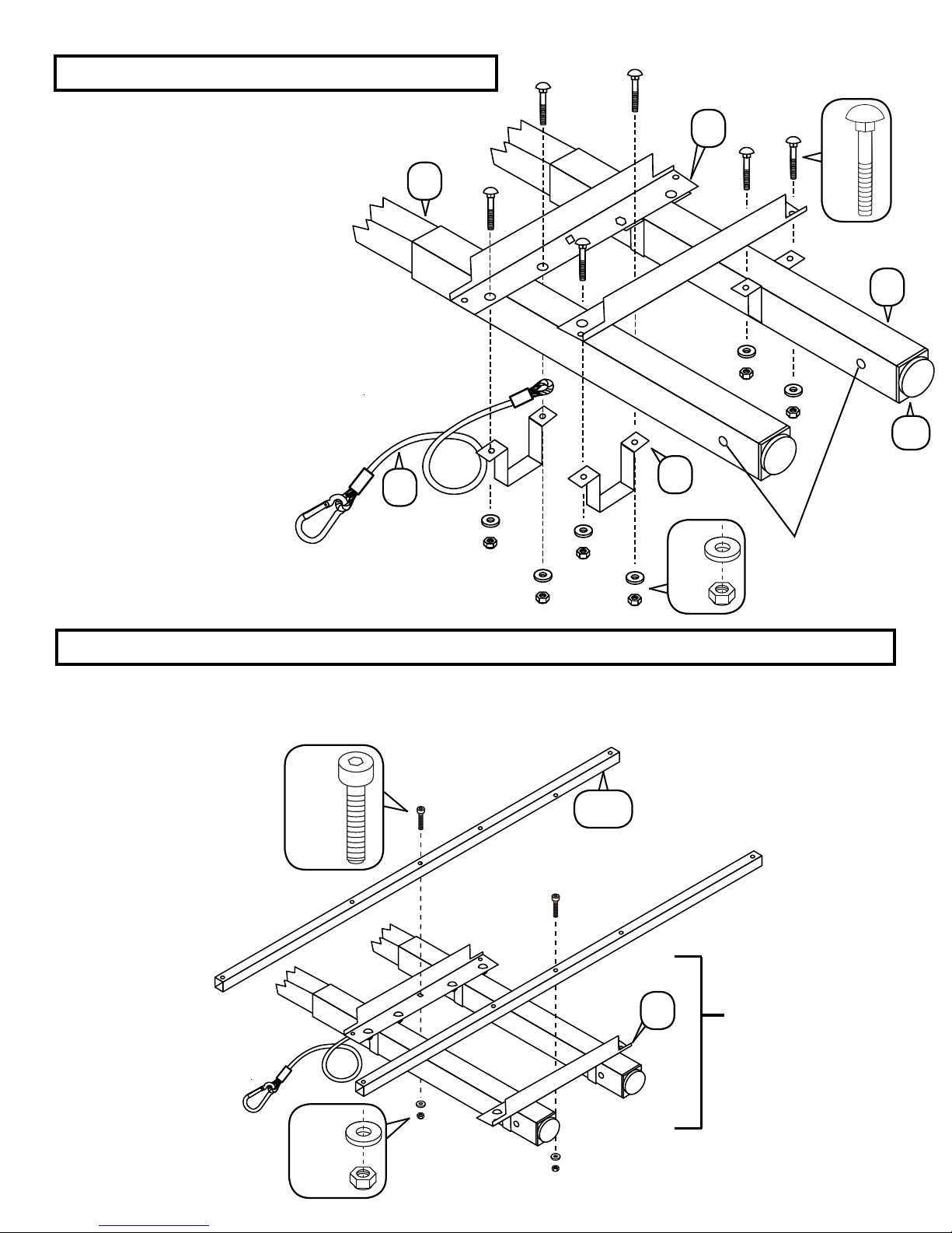
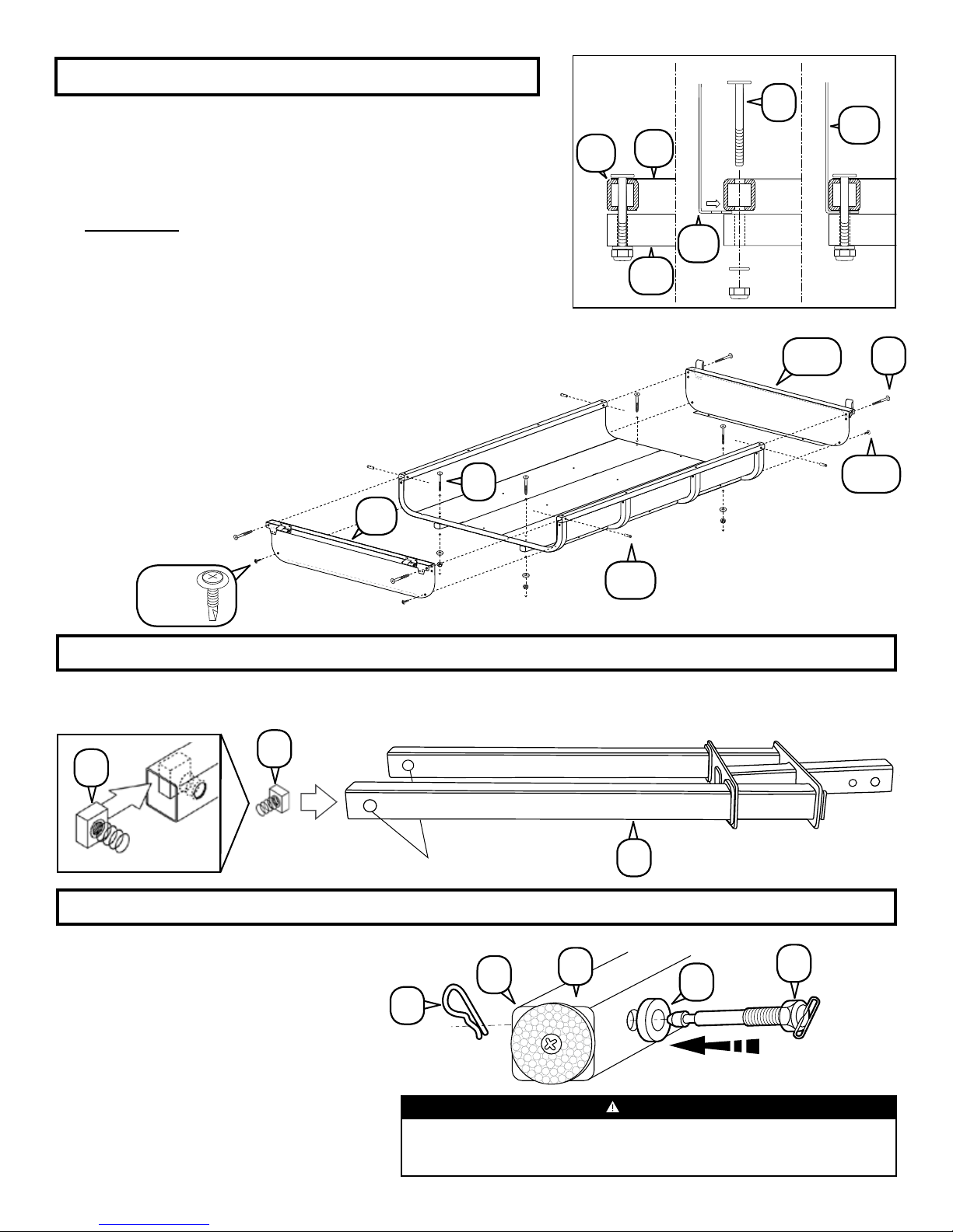
STEP 1
Slide the Female Tubes [M] over
FlatPipe Spine [A]. NOTE: The
holes at the end of the Spine and
the Females Tubes must line up for
proper assembly. Using 5/16 Carriage
Bolts, 5/16 Washers, and 5/16 Nuts
[P, Q, R] attach the Frame Angles
[N] and the Hat Brackets [O] to the
Female Tubes. The vertical portions
of the frames angles should face the
exterior of the carrier and the Hat
Brackets bolting to the frame angles
from underneath the females tubes
and spine. Install the Safety Cable [S]
by placing the looped end (the side
without the Quick Link) in between
the Hat Bracket and Frame Angle
(located closest to the vehicle, on
the passenger side, using the side
of the Hat Bracket that faces
the interior of the Spine).
Hand Tighten all connections
at this time. Install End Caps
with Reflectors [T] at the ends of the
exposed Female Tubes.
S
A
O
Q
R
N
P
M
T
Align to Flat
Pipe Spine
STEP 2
Attach the Flat Pipe Frame Mount to each Cross Tube [FF] using a 1.6” Socket Head Bolt, M6 Washer and a
M6 Nylock Nut [HH, AA, BB]. Hand tighten only at this time.
FF
HH
FLAT PIPE
N
FRAME
MOUNT
AA
BB
PAGE 6 OF 14
Page 7
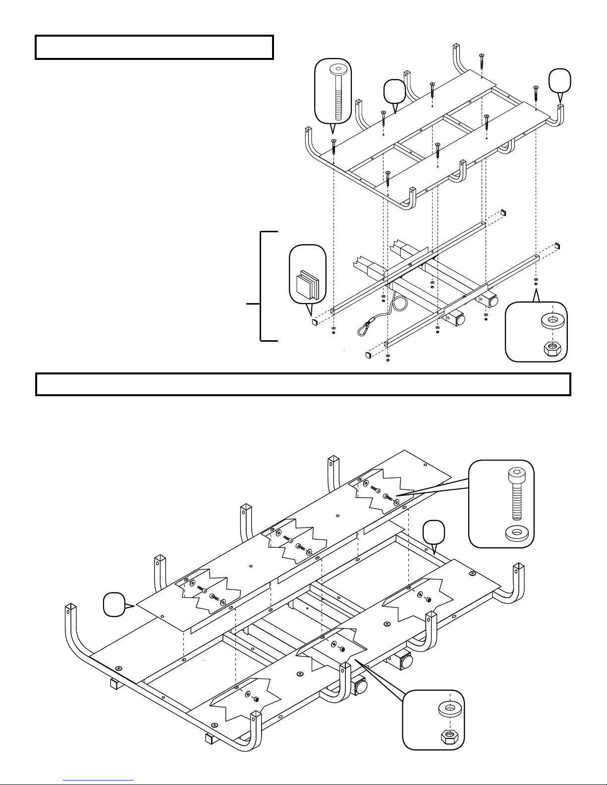
STEP 3
STEP 3: Using a M6 Washer and a M6 Nylock
Nut [AA, BB] with a 2.5” Joint Connector Bolt
[Y] join two (2) Floor Panels [V] (excluding the
third, center Floor Panel which will be attached
in the next step), four (4) U-Tubes [U], to
the assembled Cross Tubes [FF] and Frame
Angles [N] of the Flat Pipe Platform. Continue
to hand tighten only at this time.
Press four End Caps [EE] into ends of each
Cross Tube [FF].
FLAT PIPE
FRAME
MOUNT
EE
Y
U
V
AA
BB
STEP 4
Place the last Floor Panel [V] in the center on top of the U-Tubes [U]. Use M6 x 15 Socket Head Bolts, M6
Washers, & M6 Nylock Nuts [Z, AA, BB] at each of the six (6) locations on the underside of the panel to secure
the center to the outside panels. Hand tighten only at this time.
AA
U
BB
V
AA
BB
PAGE 7 OF 14
Page 8
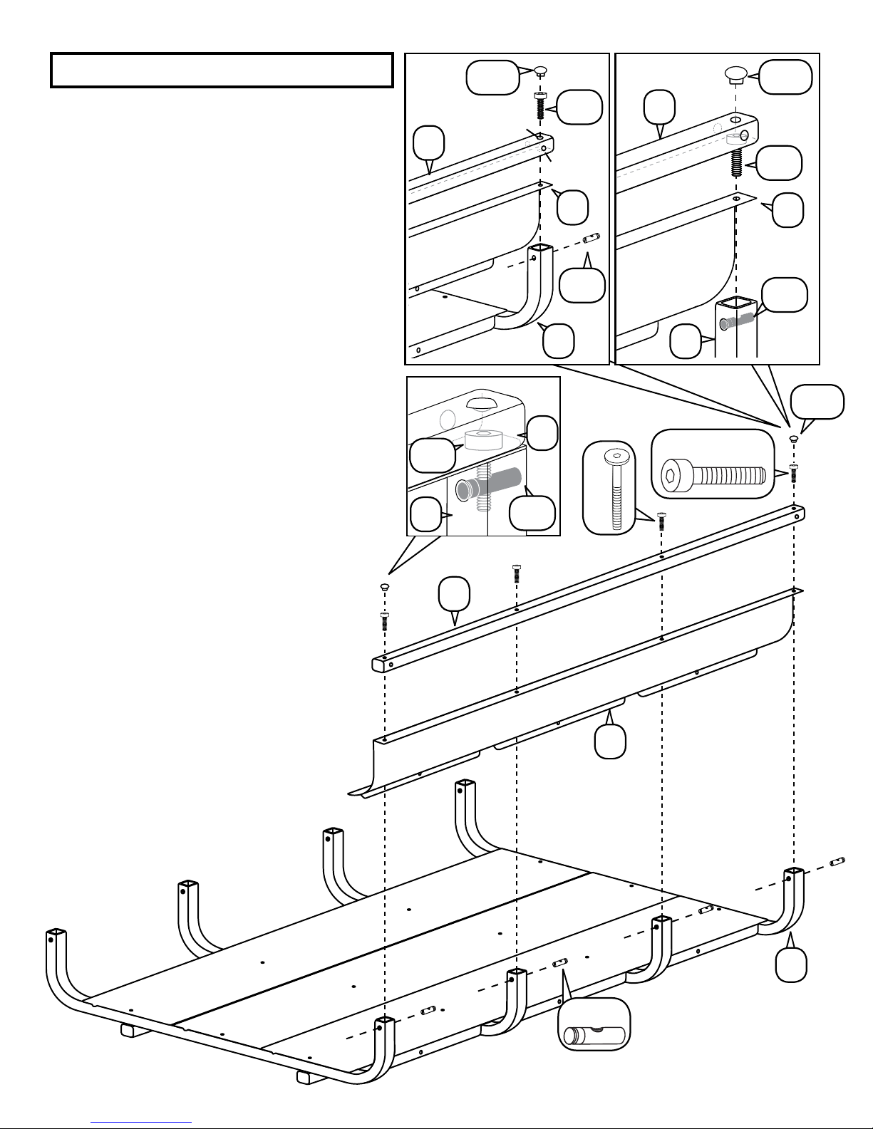
STEP 5
Using a 1.5” Socket Head Bolt [CC] and Pin Nut
[DD] on the two holes at the ends of the tubes
only, connect the Side Tubes [W] and Side
Panels [II] to the rack frame by dropping the
Socket Head Bolt through the top of the Side
Tube down through the Side Panel [Figure 1].
NOTE: There are two holes of different sizes
at each end of the side tubes, the larger holes
should face upwards to allow the head of the
bolt pass through the top and then rest on the
smaller hole on the bottom of the interior of the
tube [Figure 2].
Finish connecting the ends Side Panels and
Tubes to the U-Tubes [U] by placing a Pin Nut
[DD] Horizontally through the holes at the end of
the U-Tube and then securing the Socket Head
Bolt [CC] through the treading in the Pin Nut.
Cap these locations (4) with provided Rubber
Plugs [GG].
NOTE: For an easier match the Pin Nut is
designed with a flat head slot to illustrate the
direction of the internal thread. The knotted end
should rest on the edge of the U-Tubes [U]
hole as shown [Figure 3].
[Figure 1]
W
[Figure 3]
CC
U
W
GG
Large Hole
W
DD
CC
Small Hole
II
DD
U
[Figure 2]
GG
W
CC
II
DD
U
GG
CC
Y
Connect the center portions of the Side
Tubes [W] and Panels [II] with 1.5” Joint
Connector Bolts [Y] and Pin Nuts [DD]
(These bolts will NOT pass through the
Side Tubes as the Socket Head Bolts [CC]
did at the ends of the tube).
Hand tighten only at this time.
II
U
DD
PAGE 8 OF 14
Page 9
STEP 6
[Before] [Figure 3] [Figure 4]
With the Side Tubes and End Tubes in place. Un-bolt and remove
the two (2) 2.5” Joint Connector Bolts [Y] at each end of the rack
allowing the bottom lip of the End Panels [JJ] and [KK] to slip
between the Cross Tubes [FF] and U-Tubes [U] [Figure 3]. The
End Panel [JJ] that includes Hinge hardware must be installed on
the Drivers Side of the Vehicle. With the holes aligned, re-insert the
Joint Connector Bolts [Y] [Figure 4].
Using two (2) Joint Connector Bolts [Y] and two (2) Pin Nuts [DD]
on each side, connect the End Panels [JJ] and [KK] to the Side
Tubes [W] by passing the Bolt through over-hanging edge to the
base to of the End Panel and then threading the bolt through the Pin Nut on
the interior of the Side Tube. Secure and tighten all hardware from
previous steps of the Rack and Side Panel installation.
Locate two 3/16” dia. holes in each end panel.
Center punch an indentation at each hole
center. Drill 1/8” dia. holes into
end tube and u-shaped
tube. Insert and
tighten four self-tap
screws [C].
JJ
Y
U
DD
MM
Y
V
JJ
FF
KK
NOTE: Tip of screws [C] are self-
drilling as well. You may choose
to power drive the screws without
pre-drilling if you have the tools and
JJ
Y
MM
skill to do so.
STEP 7
Insert the second Spring Nut [G] into the forked end of the Spine [A] (customer choice of side, only one side is
needed) [Figure 5].
G
G
[Figure 4]
STEP 8
Insert the Silent Hitch Pin With Handle [D] and
Plastic Bushing [F] on the forked end of the Spine
[A] containing the second Spring Nut [G]
inside. The Pin should be inserted so
that it passes through the block portion
of the Spring Nut first and then exiting through the
spring. Tighten firmly to engage threading and apply
Retainer Clip [B] as shown.
Apply the 2-1/4” End Caps [T] with
Reflectors to the exposed end of the Spine
[A] using a Rubber Mallet.
CUSTOMER CHOICE OF SIDE
B
Never operate the vehicle without the hand-tighten Silent Hitch Pin
properly engaged to prevent the carrier from sliding while in transit.
Failure to do so may result in bodily injury and property damage.
T
A
A
WARNING:
D
F
PAGE 9 OF 14
Page 10
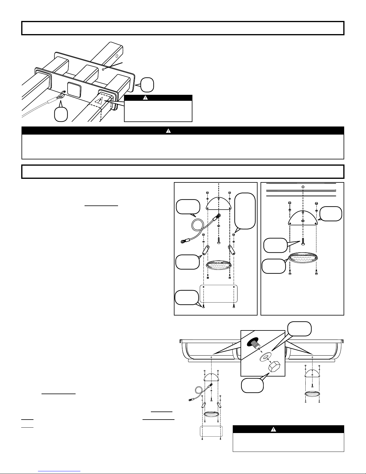
STEP 9
Optional Safety
Cable Position
Connect the Quick Link Side of the Safety Cable
[S] to one of the available hole positions located
on the frame of the Flat Pipe Spine [A].
A
WARNING:
DO NOT ALLOW HAT
BRACKETS [O] TO
S
The Safety Cable prevents the Black Box rack from sliding off the Spine when telescoped. The rack may be slide out
when parked for vehicle hatch access only. Never move the vehicle while the carrier is slid out. Failure to engage the
Safety Cable may result in bodily injury and property damage.
OVERLAP WARNING
LABEL ON FEMALE TUBE.
WARNING:
STEP 10
Un-Bolt LED Light Hardware supplied on the LED
Lights [NN] and then reattach onto LED Mount
Bracket [QQ]. For the drivers side of the vehicle
only, also include License Plate Brackets [PP] as
shown. [See Drivers Side Illustration]
Use 6 mm Hex Bolts [RR], 6 mm Nylon Nuts [SS],
and 6 mm Washer [TT] to install License Plate
(Customer Supplied License Plate Not Included)
onto License Plate Brackets [PP] as shown.
On the side of the rack furthest away from the
vehicle, use 1/4-20 X 3/4 Bolts [LL], .75” Washers
[XX] and 1/4-20 Nylock Nuts [ZZ] to install LED
Light Brackets [QQ] with mounted hardware and
LED Lights [NN] onto the Rack through the Side
Panel [II] and Floor Panel [V]. On the drivers side
only, include one Balance Cable [YY] loop end
between the LED Mount Bracket [QQ] and the .75”
Washer [XX]. [See Drivers Side Illustration]
On the other side of the rack on the side closest to the
vehicle (where the LED lights have not been installed),
secure the Side Panels [II] to Floor Panels [V] using
1/4-20 X 3/4 Bolts [LL], .75” Washers [XX] and 1/4-20
Nylock Nuts [ZZ] in the same manor excluding the
LED lights. The second Balance Cable [YY] should
also be included between the Side Panel and Washer
on the drivers side only.
Connect LED Lighting to the Wire Harness [OO] (not
shown) with the yellow wire connected to the drivers
side and the Green Wire connected to the passenger
side of the vehicle. Weave Wire Harness through the
underside of the Black Box Rack to prevent wire drag.
Connect the Wire harness to the Vehicle Trailer Light
Connection on rear of the Vehicle.
YY
PP
RR
Drivers Side
NOTE: The hole location furthest from the vehicle
is recommended for maximum slide out.
SS
TT
LL
NN
CUSTOMER SUPPLIED
LICENSE PLATE
(NOT INLCUDED)
Passenger Side
XX
ZZ
CUSTOMER SUPPLIED
LICENSE PLATE
(NOT INLCUDED)
FAILURE TO PROPERLY CONNECT WIRES TO THE
WIRE HARNESS WILL RESULT IN MISMATCHED STOP/
TURN LIGHTS AND IMPROPER SIGNALING.
WARNING
QQ
PAGE 10 OF 14
Page 11
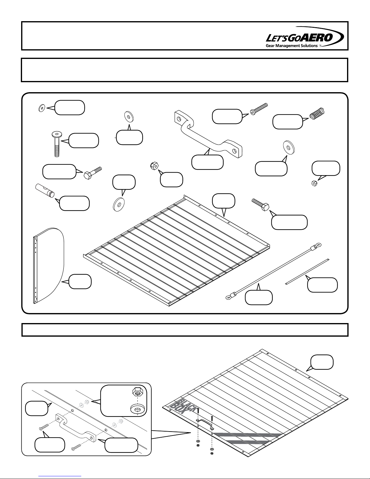
AERFOIL LID PARTS & ASSEMBLY OVERVIEW
REQUIRED TOOLS:
GGG
BBB
III
DDD
5/32” ALLEN WRENCH
RUBBER MALLET
LLL
XX
ZZ
7/16” WRENCHES
PHILLIPS SCREWDRIVER,
JJJ
AAA
HHH
UU
HAMMER
3/8” WRENCH
FFF
KKK
CCC
VV
STEP 11
Unfold AerFoil Cover [UU] and place face-up.
Install Handle [AAA] using two (2) each 10-24 x
1.25 Phillips Screws, 10-24 Nylock Nuts, 3/16 X
1 Fender Washers [JJJ, KKK, LLL]. [Figure 7]
[Figure 7]
KKK
UU
JJJ
LLL
AAA
EEE
YY
TOOL: 5/32” HEX WRENCH
UU
PAGE 11 OF 14
Page 12
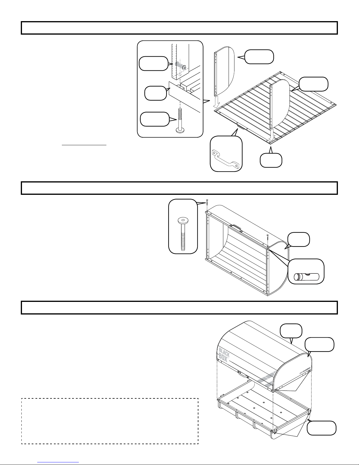
STEP 12
Passenger Side
Place the AerFoil face down so the
inner groves are exposed. Unfold Bulk
Heads
the pre-installed Joint Connector Bolt
[BBB] from the ends of the Bulk
Heads. Insert the Bulk Heads into the
groove near the edge of the AerFoil
Cover
line faces the interior of the carrier
[Figure 6]. One Bulk Head [WW]
includes pre-installed silver Latch
Keepers, be sure this Bulk Head is
placed on the Passenger side of the
vehicle
[VV] and [WW] and remove
[UU] so the Bulk Heads cut
.
DDD
UU
BBB
[Figure 6]
VV
Cut Line
WW
Drivers Side
AAA
Re-Insert Joint Connector Bolts [BBB] through the pre-installed
Pin Nuts
[DDD] and tighten.
STEP 13
NOTE: This step will be easiest if someone
assists you.
Form AerFoil Cover [UU] around Bulk Heads
[UU] inserting edges of Bulk Heads into
groove of cover as you go. Attach at remaining
two corners with pre-installed Pin Nuts [DDD]
and Joint Connector Bolts [BBB] using the
same method used in STEP 12.
STEP 14
Place the AerFoil Lid on top of cage. You should be able to
engage the Adjustable Pull Latches pre-installed to End Panel
[KK] once the Lid is positioned properly.
BBB
TOOLS: 3/8” WRENCH, PHILLIPS SCREWDRIVER, DRILL, 1/4” BIT.
UU
TOOL: 5/32” HEX WRENCH
UU
DDD
UU
WW
NOTE: If the “catch” of the Pull Latch does not meet the Latch
Keepers pre-installed on Bulk Head
raised by spinning the “catch” counter clockwise or vice versa to
be lowered.
NOTE: While Let’s Go Aero takes time to inspect and clean all
products before they leave our facility, some Plastic Shavings
may fall from AerFoil lid during the unpacking assembly
process. These are a normal result of the manufacturing
process and are knocked loose during shipment.
[WW] the “catch” can be
Latch Keeper
KK
Adjustable Pull Latch
PAGE 12 OF 14
Page 13
STEP 15
NOTE: This step will be easiest if
someone assists you.
Attach the top of the Hinges located on
End Panel
on the
Bolts
and 1/4-20 Nylock Nuts
[JJ] to the Bulk Head [VV]
AerFoil Lid using 1/4-20 X 1.25
[CCC], .3” X 1” Washers [GGG],
[ZZ] [Figure 8].
TOOLS: DRILL; 1/4” & 13/16” BITS, 3/8” & 7/16” WRENCHES, HAMMER, CENTER PUNCH
ZZ
GGG
VV
[Figure 8]
CCC
STEP 16
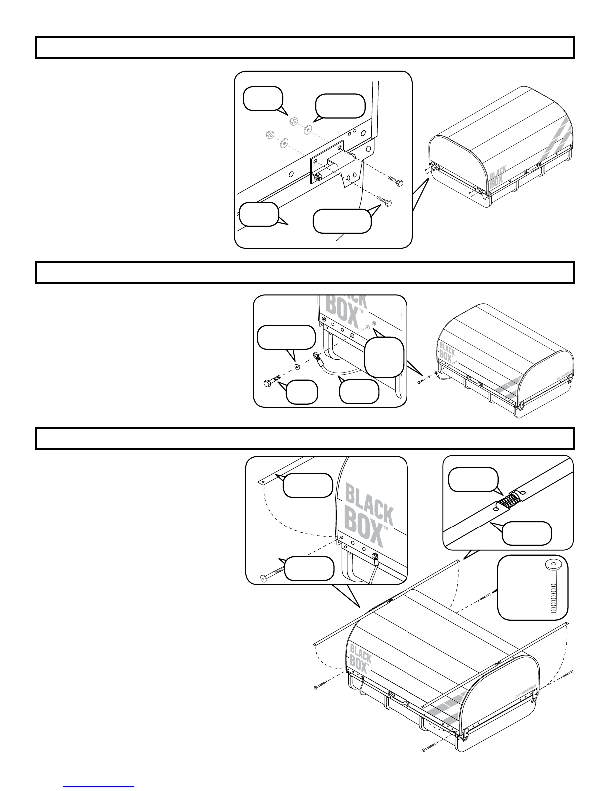
Attach the loose ends of each Balance
Cable
1/4-20 X 1.5 Bolts
Washers
1/4-20 Nylock Nuts [ZZ]
hole in from the corner of the lid as shown.
[Figure 9] (NOTE: Smaller .75” Washers
[XX] should be installed on the interior.)
[YY] to the AerFoil Cover [UU] with
[III], 1/4-20 X 1 Fender
[HHH], .75” Washers [XX], and
using the third
[Figure 9]
HHH
III
YY
STEP 17
NOTE: This step will be easiest if
someone assists you.
EEE
IMPORTANT: Remove and reattach
each bolt ONE AT A TIME before
moving to the next bolt.
Join two AerFoil Bands [EEE] together
with one Band Spring [FFF] at the
ends with the smallest holes. [Figure
10] Repeat for the remaining two
AerFoil Bands and Spring. Attach the Band/Spring
assembly to the AerFoil Cover by bending the
assembly around the top edge of the Aerfoil with
the padded side of the straps placed against the
Cover as shown. Start at one corner by removing
one Joint Connector Bolt [BBB] and then rethreading the Bolt through the larger hole at the
end of the AerFoil Band [EEE] and then into the
carrier cover [Figure 11]. Repeat this step for the other side of
the carrier with the remaining Band/Spring assembly.
BBB
XX
ZZ
[Figure 11]
7/16” WRENCHES
TOOL: 5/32” HEX WRENCH
[Figure 10]
FFF
EEE
BBB
REMOVE &
REATTACH
PAGE 13 OF 14
Page 14
ONE YEAR LIMITED WARRANTY
We warrant this Let’s Go Aero brand product during the time the original retail purchaser owns
it. This warranty terminates if a purchaser transfers the product to any other person.
Let’s Go Aero warrants this product to be free from defect in material and workmanship for
one year (retain your sales receipt for your records). Any product or part thereof found to be
defective within that period will be replaced without charge provided that: (1) the product was
not misused; (2) no alterations or modifications were made; (3) its failure was not a result of
normal wear expected in the use of the product; (4) the product or part is delivered, freight
prepaid, to Let’s Go Aero.
Manufacturers only obligation shall be to replace such products or parts proved to be defective.
A Return Merchandise Authorization is required prior to return. Please contact Let’s Go Aero
toll-free, at 877-464-2376 or 719-630-3800, or via email to [email protected] to get an
RMA number.
No warranty is given for LGA products purchased outside of the United States and Canada.
To register your product, visit the Let’s Go Aero website at www.LetsGoAero.com
Technical Suppor t
For assistance with this product, please contact us:
Let’s Go Aero, Inc.
4474 Barnes Road
USA
Phone: 877-464-2376 or 719-630-3800
Email: [email protected]
To learn more about our products and stay informed about useful options for transporting all kinds of
gear with your carrier, be sure to visit our website: www.LetsGoAero.com
Patent Numbers 6,609,725; 6,945,550; 8,079,613; D717718; 8,858,141; Patents Pending
Copyright© 2017, Lets Go Aero, Inc., All rights reserved.
Patent and trademark protected.
PAGE 14 OF 14
 Loading...