

Page 1

Heating is great
when you control it.
USER
MANUAL
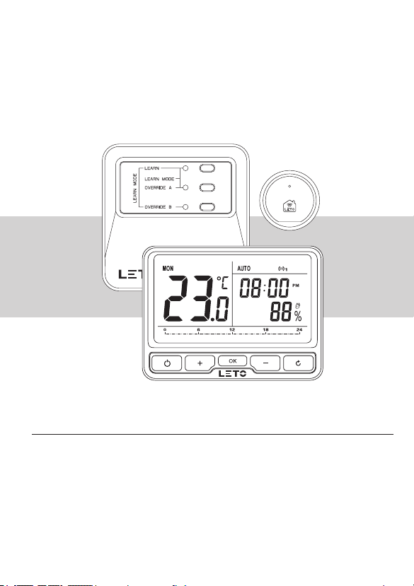
Wireless Programmable
Room Thermostat
Model No.: LS99111010
Scan for App
Page 2

Contents
1. Overview
2. System Installation
2.1 Install and Wiring Receiver
2.2 Activate Batteries and Install Thermostat
2.3 System Check
3. Operation Thermostat
3.1 Clock Setting
3.2 Program Setting
3.3 Override Mode
3.3 Manual Mode
3.3 Holiday Mode
3.3 ECO Mode
3.3 OFF Mode (Frost Protection)
3.3 Child Lock
4. User Option
5. User Options Table
6. Product Specication
6.1 Wireless Programmable Thermostat
6.2 Wireless Receiver
6.3 Wireless Wi-Fi Gateway
.......................................................................................................
...................................................................................
........................................................................
2.1.1 Install Receiver
2.1.2 Wiring Receiver
2.2.1 Activate Batteries
2.2.2 Install Thermostat
2.3.1 RF Address Code Setting
2.3.2 RF Communication Check
3.2.1 Pre-set Program
3.2.2 To adjust the Pre-set Program
................................................................................
...............................................................................
.............................................................................
............................................................................
...........................................................................................
..............................................................................
.............................................................................................
........................................................................................
..............................................................................
...........................................................................................
.............................................................................................
............................................................................................
.................................................................................................
....................................................................
..................................................................................................
..................................................................................................
....................................................................................
...............................................................................
.....................................................................................
............................................................................
..................................................
................................................................
..............................................................
.........................................................
.........................................................
01
02
02
02
03
06
06
06
07
07
12
13
13
15
15
15
17
18
19
20
21
21
22
23
24
24
25
25
Page 3

▪ This wireless programmable room thermostat kit can be used to control heating boiler,
a variety of valves and actuators.Can be operated remotely via App. by smartphone,
pad or PC.
▪
It contains a wireless programmable room thermostat LTC10, a wireless receiver
LTR10, and a WI-FI gateway LTG10 accessing your thermostat to Internet. Three units
are linked by Radio Frequency.
▪ This thermostat is a programmable room thermostat 5+2 Days / 7 Days / 1 day product.
5+2 days allows you to set a program for weekdays and a program for the weekend.
7 days allows you to set a same program for every day of the week. 1 day functionality
allows you to set a different program for every day of the week. Each program type allows
you to set 7 time and temperature events.
Controls and Display Layout
Days
Temperature
Program setting time
ECO
+ or – buttons for setting adjustment
Conrm
Return
Auto, Manual, Holiday mode
RF
Time
Humidity
Gateway control button
L
Copy Clock set
Child lock
Program set
Frost protection
Heating
Low battery warning
Open window
11. Overview
Page 4

2. System Installation
2.1 Install and wiring receiver
2.1.1 Install receiver
Follow the installation diagrams to install and connect the receiver LTR10 correctly.
Note: 1 The installation and wiring should be operated by trained personnel.
Note: 2 The Receiver should be mounted in a suitable location that is both accessible for
the connection of mains and control wiring, and allows good reception of the RF
signal. The Receiver needs a 100~240 V AC mains supply to operate, and this
should be fused appropriately (5 A max.).
Note: 3 The Receiver should be mounted in a location where it will not come into contact
with water, moisture or condensation.
2
Loosen the screw on the
receiver’s bottom. (No need
to screw out completely)
Fasten the terminal base
on wall with 4 screws
Open the upper cover
Loosen the screws on terminals,
wiring the terminal correctly, then
fasten the screws
Page 5

Close the upper cover
Press the area as below picture mentioned,
fasten the screw, after make sure no gap
between upper and lower covers, as well as
all the terminals will be connected
2.1.2 Wiring receiver
Note: 1 Install in accordance with local wiring regulations.
Note: 2 The wiring should be operated by trained personnel.
Note: 3 Observe ambient temperature and current limits (see product data sheet).
Note: 4 These diagrams must be read in conjunction with any boiler or cylinder manufac-
tures instructions.
Note: 5 Leto Smart accepts no liability for any loss or damage arising from any errors
or omissions that may be inadvertently contained within these diagrams. They
are proposal diagrams only, not certified wiring diagrams.
32. System Installation
Page 6

2. System Installation
Volt free contacts
Burner (direct control)
LTR 10
Combi boiler
LTR 10
4
Page 7

2. System Installation
Electric heater
LTR 10
Thermal actuator
LTR 10
Zone valve
LTR 10
5
Page 8

2. System Installation
2.2 Activate battery and install thermostat
2.2.1 Activate battery
2.2.2 Install Thermostat
This thermostat could be desk-stand if open the back support, you just need to place it on
any at surface allows to receive RF signal.
If you want to hang it on the wall, use the template provided.
Drill two holes in the wall and tighten the screws, ensuring two holes’ distance is 81.5 mm;
then, x the thermostat’s back cover by putting it over the screw head.
6
Page 9

2.3 System Check
2.3.1 RF signal pairing
The room thermostat has already been pre-bound with receiver’s
OVERRIDE
to RF signal pairing between room thermostat and gateway, please refer
to 2.3.1.B.
I in kit LS99111010 when delivered. You may directly move
A. RF signal pairing between room thermostat and receiver
Preparation: thermostat and receiver should be powered/wired correctly, make sure
the visible distance between thermostat and receiver is not more than 5 meters.
Start receiver’s RF pairing mode by hold-pressing on its LEARN button for 3 seconds,
receiver is ready for RF signal pairing when its light ashing.
Press OVERRIDE I or II (you must choose according to your real wiring work on
receiver) to pair with thermostat; when light of OVERRIDE I or II is ashing, it means
OVERRIDE
press to enter RF pairing interface.
I or II is ready to pair with thermostat next.
Thermostat sends pairing command with reciver:
(4-1) Long press
to enter Menu Selection,when are ashing,
72. System Installation
Page 10
82. System Installation
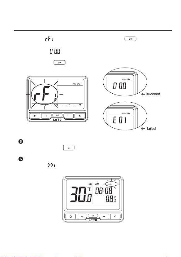
(4-2) When
pairing command with receiver;
Pairing succeed if
is ashing on screen’s right side. In this case, you need to send the pairing command with
receiver by pressing once again until pairing success.
Exit pairing mode by pressing LEARN button: thermostat’s HOME page can be
returned by keep pressing .
Once thermostat and receiver were paired successfully, and their RF communication
started normally, will show up on the top right corner of thermostat’s screen.
is ashing on the screen’s left side, press to send the
ashing on screen’s right side, pairing failed if E01 or E02
Page 11
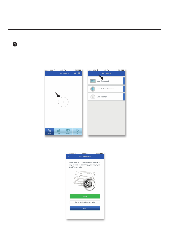
B. RF signal pairing between room thermostat and gateway
Automatically pairing thermostat with gateway by App. on iOS or Android
device
(1-1) Open the App. which connected with gateway (how to add a gateway on App.
please refer to gateway’s manual for details), choose Add Thermostat from the interface;
Add Product
(1-2) Add thermostat by scanning it’s QR code or typing MAC ID manually.
92. System Installation
Page 12
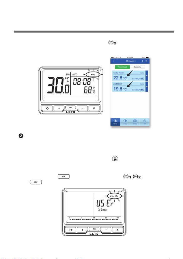
(1-3) Pairing process between thermostat and gateway might take about 1 minute.
Once thermostat is paired with gateway successfully, will show up on the top
right corner of thermostat’s screen; App. interface also show up the added thermostat’s
information.
Manually pairing thermostat with gateway
(2-1) Preparation: powered gateway correctly by plug-in socket, the LED on gateway will
be blinking rapidly (LED blinking rapidly means no connection between gateway and server).
(2-2) Start gateway’s pairing mode by hold pressing
(2-3) Thermostat sends pairing command with receiver:
(2-3-1) Long press
press to enter RF pairing interface.
to enter Menu Selection,when are ashing,
until its LED is blinking slowly.
102. System Installation
Page 13
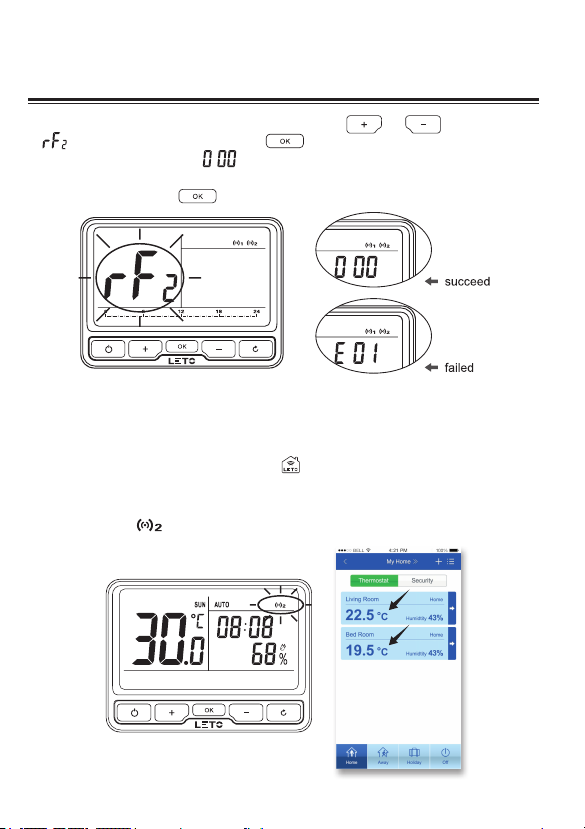
(2-3-2) On RF pairing interface, select by pressing on or until ashing
show up on screen’s left side, press to send thermostat’s pairing command
to gateway; pairing success if ashing on screen’s right side, pairing failed if E01 or
E02 is ashing on screen’s right side, in this case, you need to send the pairing command
with receiver by pressing once again until pairing success.
(2-4) Gateway is still under pairing mode even one thermostat’s pairing succeed, if you
have more thermostats need to be paired, you may continue to pair them with gateway
manually. (1 gateway could RF communicate with 10 thermostats at one time).
(2-5) Exit pairing mode by hold-pressing
pairing.
(2-6) Once thermostat and gateway were paired successfully, their RF communication
started normally,
will show up on the top right corner of thermostat’s screen.
until the LED recover ro its status before
112. System Installation
Page 14
122. System Installation
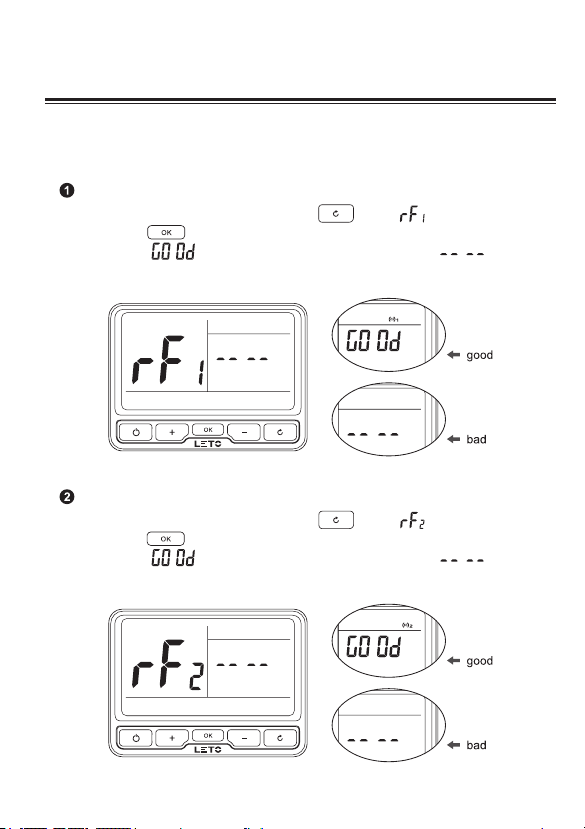
2.3.2 RF communication test
To make sure RF communication between thermostat and receiver, thermostat and gateway
before using them regularly, you should take a RF communication test.
RF communication test between thermostat and receiver
Enter RF Communication Test by long pressing , when show up on screen’s
left side, press to test RF communication between thermostat and receiver; test
result is good if show up on screen’s right side, otherwise, will show
up on screen’s right side, in this case, you need relocate the thermostat and do the test
once again.
RF communication test between thermostat and gateway
Enter RF Communication Test by long pressing , when show up on screen’s
left side, press to test RF communication between thermostat and gateway; test
result is good if show up on screen’s right side, otherwise, will show
up on screen’s right side, in this case, you need relocate the thermostat and do the test
once again.
Page 15
3.1 Clock Setting
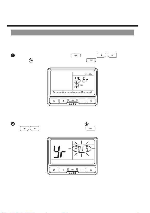
Clock setting should be done if thermostat was used for the rst time or after batteries
changed; automatically clocking setting will be done if thermostat was connected with
Internet via Gateway.
Enter Menu Selection by long pressing , select by until there
is a ashing , then enter Clock Setting by pressing .
Firstly set Year after entered Clock Setting, when appeared on Temperature Area,
press to select current year and press to set.
132. System Installation
Page 16
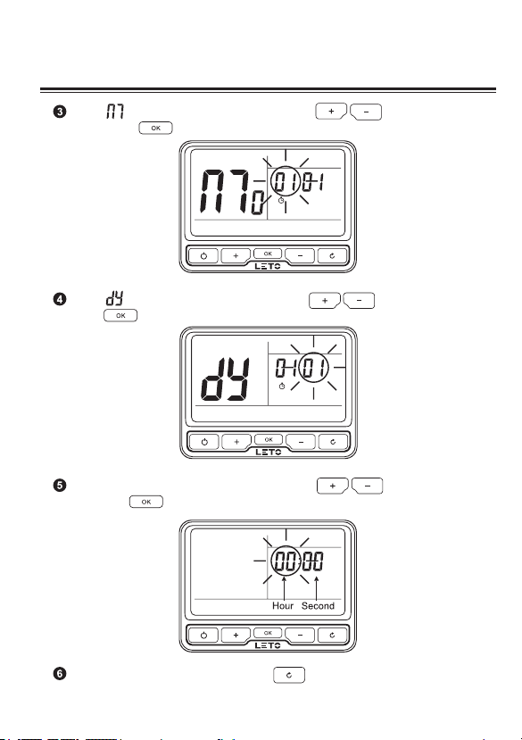
When appeared on Temperature Area, press to select current
month and press to set.
When appeared on Temperature Area, press to select current date
and press to set.
When clock setting is ashing on Time Area, press to select current
time and press to conrm.
143. Operation Thermostat
Back to the last setting menu by pressing .
Page 17
153. Operation Thermostat
3.2 Program Setting
3.2.1 Pre-set Program
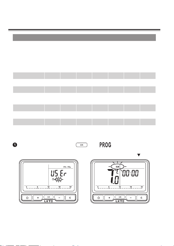
This thermostat comes with the following default settings pre-programed for your
convenience:
Working days’ pre-set program
Event 1 2 3 4 5 6 7
Time 00:00 6:30 8:30 12:00 14:00 16:30 22:30
Temperature 7 20 16 16 16 21 7
Weekend’s pre-set program (Sat., Sun.)
Event 1 2 3 4 5 6 7
Time 00:00 7:00 9:00 12:00 14:00 16:30 23:00
Temperature 7 20 18 21 18 21 7
3.2.2 To adjust the pre-set program
Enter Program Setting by Pressing when is ashing.
Program Setting menu
Page 18
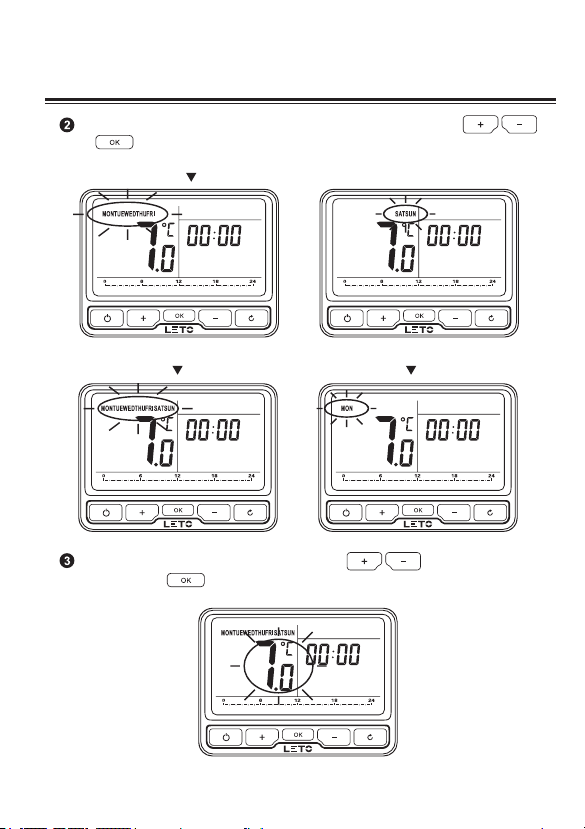
Enter 5+2 days / 7 days / 1 day program when Days ashing, select by
press to conrm.
5+2 Days Program
7 Days Program 1 Day Program
Temperature ashing in Temperature Area, press to adjust required
temperature, press to conrm.
163. Operation Thermostat
Page 19
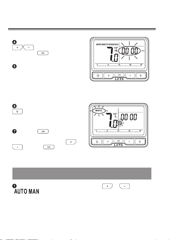
Time ashing in Time Area, press
to adjust the 1st time as
required, press to conrm.
Once the temperature and 1st time
has been set, temperature ashing
in Temperature Area again, then you
repeat to set the next temperature and
time periods, as above steps showing
(checking from Step 3).
To cancel the program by pressing
, go back to Menu Selection by
keeping pressing.
Long press can copy current
ashing day’s program setting to other
day; select target day by pressing
, long press to conrm
and paste.
3.3 Override Mode to change temperature for a short period
under AUTO mode
173. Operation Thermostat
Under AUTO mode, enter Override mode by pressing or ,
appeared on upper right.
Page 20
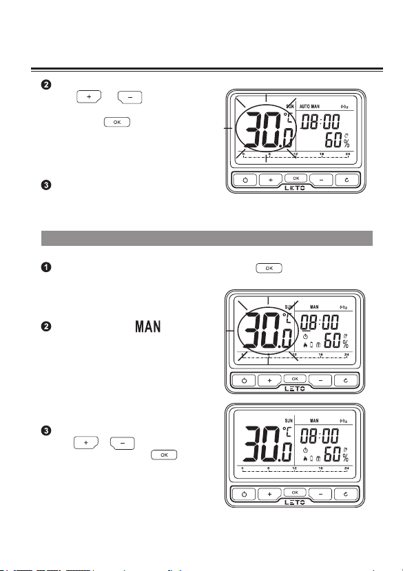
3. Operation Thermostat
Adjust required temperature by
pressing or , conrm the
override temperature after ashing for 7
sec. or pressing then continue
to show current temperature.
Exit Override Mode until next change in
the pre-set program.
3.4 Manual Mode to set a constant room temperature manually
Switch between AUTO and Manual Mode by pressing .
Under Manual mode,
appeared on upper right and temperature
ashing. Figure as following.
Adjust required temperature by
pressing or , conrm after
ashing for 7 sec. or pressing ,
then continue to show current temperature.
18
Page 21
193. Operation Thermostat
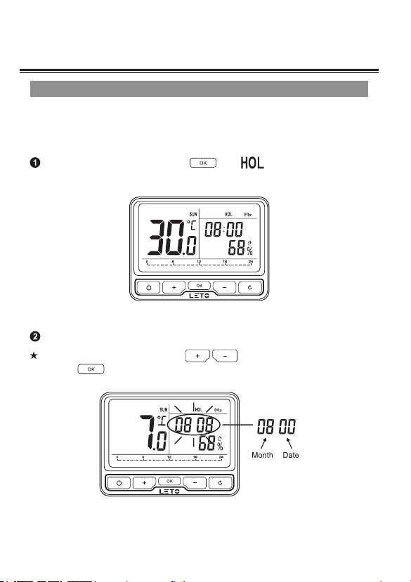
3.5 Holiday Mode
Make a holiday plan, it will keep your room at the pre-set temperature until your return time is
coming. The default temperature for Holiday Mode is 7 °C, you also can change this default
value in User Options.
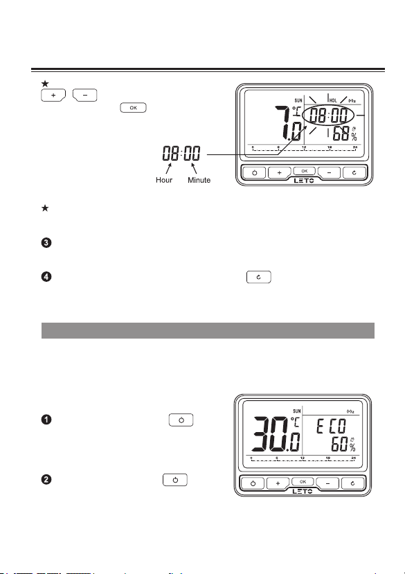
Enter Holiday Mode by keep pressing until showing on upper right.
Pre-set date and time for holiday start and return.
Holiday start date: adjust by pressing as following gure, conrm
by pressing .
Page 22
203. Operation Thermostat
Holiday start time: adjust by pressing
conrm by pressing
Return date and time’s pre-set: once Holiday Start’s date and time has been set, start
to set return date and time in the same way.
Holiday Mode will start automatically when holiday start time is coming, otherwise, it
continue AUTO Mode.
To cancel Holiday Mode’s setting by keep pressing .
as following gure,
.
3.6 ECO Mode
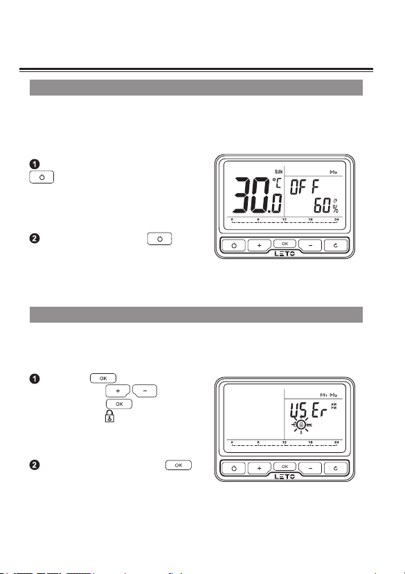
It is a quick access to energy saving but also maintain comfort. Under ECO Mode, the
room will be always kept at a pre-set temperature unless you exit this mode. The default
temperature is 9 °C, you can change this default value in User Options.
Enter ECO mode by pressing ,
following is the gure.
Exit ECO Mode by pressing .
Page 23
213. Operation Thermostat
3.7 OFF Mode (Frost Protection)
Under OFF Mode, your room’s Frost Protection will be automatically turned on unless you
exit the mode. The default temperature is 7 °C, you can change this default value in User
Options.
Enter OFF Mode by long pressing
, following is the gure:
Exit OFF Mode by pressing .
3.8 Child Lock
To avoid wrong operation by child, this thermostat has Child Lock function; once started this
function, there will be no reaction if short press on any button.
Long press to enter Menu
Selection, select by ,
conrm by pressing to open Child
Lock function when is ashing.
Cancel Child Mode by long press .
Page 24
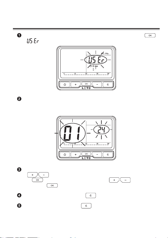
You may change user operation after entered User Operation by Pressing
when is ashing under Menu Selection.
Under User Option, the option ID is showing on Temperature Area (screen left side),
the Option Content is shown on Time Area (screen right side).
Option ID is ashing under User Option (details to see User Options Table below),
press to scroll through selectable options, select the target Option ID by
pressing ; then, adjust the User Option by pressing and set it
down by pressing .
224. User Option
To cancel User Operation’s setting, press when Option Content ashing.
To exit User Operation’s setting, press when Option ID ashing.
Page 25
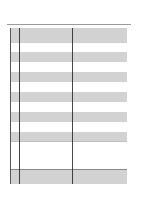
ID Option Content Min. Max. Default
Change 12h or 24h clock 12 24 24
1
Change to another pre-set
2
programme
Switch on/off summer/winter time OFF ON ON
3
Change temperature offset °C -5 5 0
4
Restore the factory Settings OFF ON OFF
5
To disable Off function OFF ON OFF
6
Frost Protection OFF ON ON
7
Pre-set the lowest temperature 7 32 7
8
Pre-set the highest temperature 7 32 32
9
Pre-set the ECO temperature 7 32 9
10
Valve Protection (unit: min., if the
valve has not been opened for
24 hours, it will be automatically
11
opened every 10:00 am; “0” means
no Valve Protection)
1 3 1
0 5 0
234. User Options Table
Activate Smart Remote Control
12
(via App. by smartphone, pad or PC)
OFF ON
OFF
(ON for Wi-Fi
thermosta)
Page 26
5.1 Wireless Programmable Room Thermostat Leto LTC10
Operating Temperature 0…50 °C
Control mode
Display
Transmitting frequency
Communication Range
(open space)
Power supply
Battery life
Heating system
LCD with backlight
868 MHz, 2 way
100 meters
2 AA alkaline batteries
Typically 2 years
245. Product Specication
Temperature setting range
Temperature control accuracy
Measurement interval
Frost protection temperature
Humidity range
Humidity accuracy
Time display
IP class
Standard
Dimensions (H×W×D)
Weight
7…32 °C (0.5 °C step)
±0.5 °C
every minute
7 °C
10…90 % rH
±5 % rH
12 hour / 24 hour
IP30
CE
117.2 × 87.2 × 26.6 mm
211 g with battery
Page 27

5.2 Wireless Receiver Leto LTR10
Operating Temperature 0 to 50 °C
Transmitting frequency
Communication Range
Power
Power supply
868 MHz
100 meters
2 W
100~240 VAC, 50 HZ
255. Product Specication
Switch rating
Switch Type
IP class
Standart
Dimensions (H×
W×D)
Weight
5.3 Wireless Wi-Fi Gateway Leto LTG10
Operating Temperature
Transmitting frequency
Communication Range
Power
Power supply
Connection
IP class
Standart
Dimensions (H×W×
D)
240 VAC 50 Hz, 5 A resistive, 2 A inductive
SPDT relay
IP30
CE
98.3 × 98.3 × 31.3 mm
145 g
0 to 50 °C
868 MHz
100 meters
1.5 W
100~240 VAC, 50 HZ
Wi-Fi (2.4 G)
IP30
CE
98.3 × 98.3 × 31.3 mm
Page 28
Leto Smart
Ukraine, 02081, Kyiv, 7-D Zdolbunivska Street
+380 (44) 338 30 70
www.letosmart.com
 Loading...