

Page 1
LESTRONIC II BATTERY CHARGER
LOOK FOR THIS SYMBOL TO POINT OUT SAFETY PRECAUTIONS. IT MEANS:
BECOME ALERT—YOUR SAFETY IS INVOLVED.
IF YOU DO NOT FOLLOW THESE
MODEL 13110 TYPE 24LC25-8ET
PLEASE SAVE THESE IMPORTANT SAFETY AND OPERATING INSTRUCTIONS
For correct operation of the equipment, it is important to read and be familiar
with this entire manual before installing and operating the charger.
DO NOT DISCARD THIS MANUAL AFTER READING.
SAFETY INSTRUCTIONS, INJURY OR PROPERTY DAMAGE CAN OCCUR.
INTRODUCTION
The Lestronic II battery charger is designed to
recharge deep-cycle, lead-acid batteries. A
ferroresonant transformer is used to provide a highly
reliable, line compensating unit with a minimum of
moving parts, designed for long, trouble-fre e service.
A patented electronic controller turns the charger on
and off automatically. This controller determines full
charge of the batteries by measuring the rate at which
the battery voltage increases during charge. When
the voltage stops rising, the battery is fully charged
and the charger turns off.
INITIAL INSTALLATION
The AC line to which the charger is to be connected
must be capable of supplying 10 amperes of AC
power.
CAUTION: TO REDUCE THE RISK OF FIRE,
USE THIS CHARGER ONLY ON CIRCUITS
PROVIDED WITH BRANCH CIRCUIT PROTECTION
(CIRCUIT BREAKER OR FUSE) OF A MAXIMUM
OF 20 AMPERES, IN ACCORDANCE WITH THE
NATIONAL ELECTRICAL CODE, ANSI/NFPA 70,
AND ALL LOCAL CODES AND ORDINANCES.
The use of an extension cord with the charger should
be avoided. The use of an improper extension cord
could result in a risk of a fire or electric shock. If an
extension cord must be used, use a three-conductor,
No. 12 AWG cord with ground, properly wired, in good
electrical condition and keep it as short as possible.
Make sure that the pins on the plug of the extension
cord are the same number, size, and shape as that of
the plug on the battery charger. Locate all cords so
that they will not be stepped on tripped over, or
otherwise subjected to damage or stress.
Do not operate this charger with a damaged cor d or
plug. Do not operate this charger if it h as received a
sharp blow, was dropped or otherwise damaged in
any manner; refer to a qualified service agent.
Provide adequate ventilation for the batteries and
charger. The convection-cooled design requires an
unobstructed flow of cooling air for proper operation.
Keep all charger ventilation openings at least two
inches (2") (5cm) away from walls and other objects.
Do not allow clothing, blankets, or other material to
cover the charger.
WARNING: CHARGERS CAN IGNITE
FLAMMABLE MATERIALS AND VAPORS. DO
NOT USE NEAR FUELS, GRAIN DUST,
SOLVENTS, THINNERS OR OTHER
FLAMMABLES.
WARNING: KEEP DRY; DO NOT EXPOSE TO
RAIN. FOR STORAGE, KEEP CHARGER IN A
BUILDING. REPLACE WORN, CUT, OR DAMAGED
POWER CORDS OR WIRES IMMEDIATELY.
www.lesterelectrical.com 1 00988J
Page 2
GROUNDING INSTRUCTIONS
This battery charger must be grounded to reduce the
risk of electric shock. This charger is equipped with an
electric cord having an equipment-grounding
conductor and a grounding type plug. This plug must
be connected to an appropriate receptacle that is
properly installed and grounded in accordance with
the National Electrical Code and all local codes and
ordinances.
DANGER: IMPROPER CONNECTION OF THE
EQUIPMENT-GROUNDING CONDUCTOR CAN
RESULT IN RISK OF ELECTRIC SHOCK.
The conductor with insulation having an outer surface
that is green, with or without yellow stripe(s), is the
equipment-grounding conductor. If repair or
replacement of the electric cord or plug is necessary,
do not connect the equipment-grounding conn ector to
a live terminal.
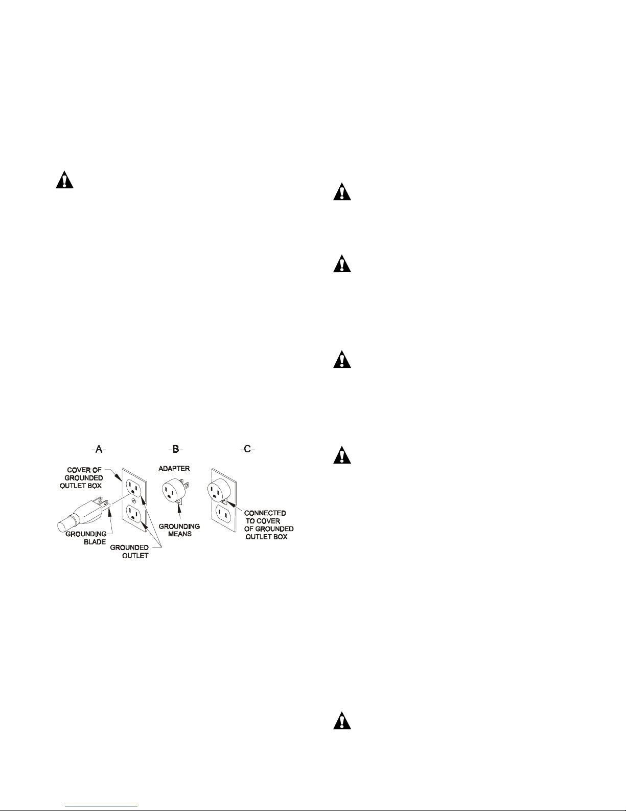
Battery chargers equipped with a grounding plug as
illustrated in Figure A are for use on a nominal 115 volt
circuit. A temporary adapter, as illustrate d in Figures
B and C, may be used to connect this plug to a tw opole receptacle as shown in Figure C if a properly
grounded outlet is not available. The temporary
adapter should be used only until a properly groun ded
outlet can be installed by a qualified electrical. The
green-colored rigid ear or lug extending from the
adapter must be connected to a permanent ground
such as a properly grounded outle t box.
GROUNDING METHODS
!!!DO NOT MAKE ANY CONNECTIONS UNTIL YOU
CHECK THE CHARGER NAMEPLATE AND
VERIFY THAT THE CHARGER IS FOR USE ON
THE INTENDED INPUT POWER, BATTERY
SYSTEM VOLTAGE, BATTERY TYPE, AND
BATTERY AMP-HOUR CAPACITY SIZE!!!
1. With the charger DC output cord disconnected
from the batteries, connect the power supply cord
to the needed AC voltage and frequency as
specified on the charger nameplate.
WARNING: TO REDUCE THE RISK OF AN
ELECTRIC SHOCK, CONNECT THE AC POWER
SUPPLY PLUG ONLY TO A PROPERLY
GROUNDED, SINGLE PHASE (3-WIRE) OUTLET.
REFER TO GROUNDING INSTRUCTIONS.
CAUTION: MAKE SURE THE BATT ERY PACK
IS THE CORRECT NUMBER OF SERIES
CONNECTED LEAD-ACID CELLS SYSTEM
VOLTAGE, AND AMP-HOUR CAPACITY AS
SPECIFIED ON THE CHARGER. USE OTHERWISE
MAY DAMAGE THE CHARGER AND/OR
BATTERIES.
DANGER: TO PREVENT ELECTRIC SHOCK,
DO NOT TOUCH UNINSULATED PARTS OF THE
CHARGER OUTPUT CONNECTOR, BATTERY
CONNECTOR, OR BATTERY TERMINALS. MAKE
SURE THAT BOTH THE CHARGER AND BATTERY
CONNECTORS ARE IN GOOD WORKING
CONDITION.
NOTE: The use of the adapter shown in Figures B
and C is not permitted in Canada.
Battery chargers for use on a circuit having a nominal
rating of more than 115 volts are equipped with a
specific electric cord and plug to permit the connection
to a suitable AC receptacle. Make sure that the
charger is connected to a receptacle having the same
configuration as the plug. No adapter should be used
with these chargers.
NORMAL OPERATION
REFER TO and FOLLOW ALL the instructions and
safety precautions printed on the charger before every
use!
DANGER: DO NOT USE THE CHARGER IF
EITHER THE CHARGER OR BATTERY
CONNECTORS ARE CORRODED, CRACKED,
SHOW ANY SIGNS OF MELTING ARE DAMAGED
IN ANY WAY OR DO NOT MAKE A TIGHT CLEAN
ELECTRICAL CONTACT. USING ANY CHARGER
WITH ANY OF THE ABOVE SYMPTOMS COULD
RESULT IN A FIRE, PROPERTY DAMAGE, OR
PERSONAL INJURY. REPLACE DEFECTIVE,
CRACKED OR DAMAGED CORDS OR WIRES
IMMEDIATELY. DO NOT DISASSEMBLE
CHARGER; TAKE IT TO A QUALIFIED SERVICE
AGENT WHEN SERVICE OR REPAIR IS
REQUIRED. INCORRECT REASSEMBLY MAY
RESULT IN RISK OF ELECTRIC SHOCK OR FIRE.
2. Connect the charger to a battery system of the
voltage, type, and amp-hour capacity as specified
on the charger. Connect DC output connector to
the battery connector by gras ping the plug body or
handle firmly pushing the plug straight into the
receptacle until the connectors are fully engaged.
WARNING: DO NOT DISCONNECT THE DC
OUTPUT CONNECTOR FROM THE BATTERY
RECEPTACLE WHEN THE CHARGER IS
www.lesterelectrical.com 2 00988J
Page 3
OPERATING. THE RESULTING ARCING AND
Minimum
BURNING OF THE PLUG AND RECEPTACLE
COULD CAUSE THE BATTERIES TO EXPLODE. IF
THE CHARGER MUST BE STOPPED, FIRST
DISCONNECT THE AC POWER SUPPLY CORD
FROM ITS OUTLET, THEN DISCONNECT THE
CHARGER DC OUTPUT PLUG FROM THE
BATTERY RECEPTACLE.
Three to five (3-5) seconds after the ch arger and
battery connectors are engaged, the control relay
inside the charger will click "closed", indicating a
complete electrical circuit between the controller
kit inside the charger and the equipment battery
pack.
After the relay clicks "closed", the transformer will
hum indicating that the transformer has been
energized by AC power.
After the transformer hums, the ammeter needle
will deflect indicating initial charge rate.
3. MONITOR THE AMMETER FOR THE INITIAL
CHARGE RATE
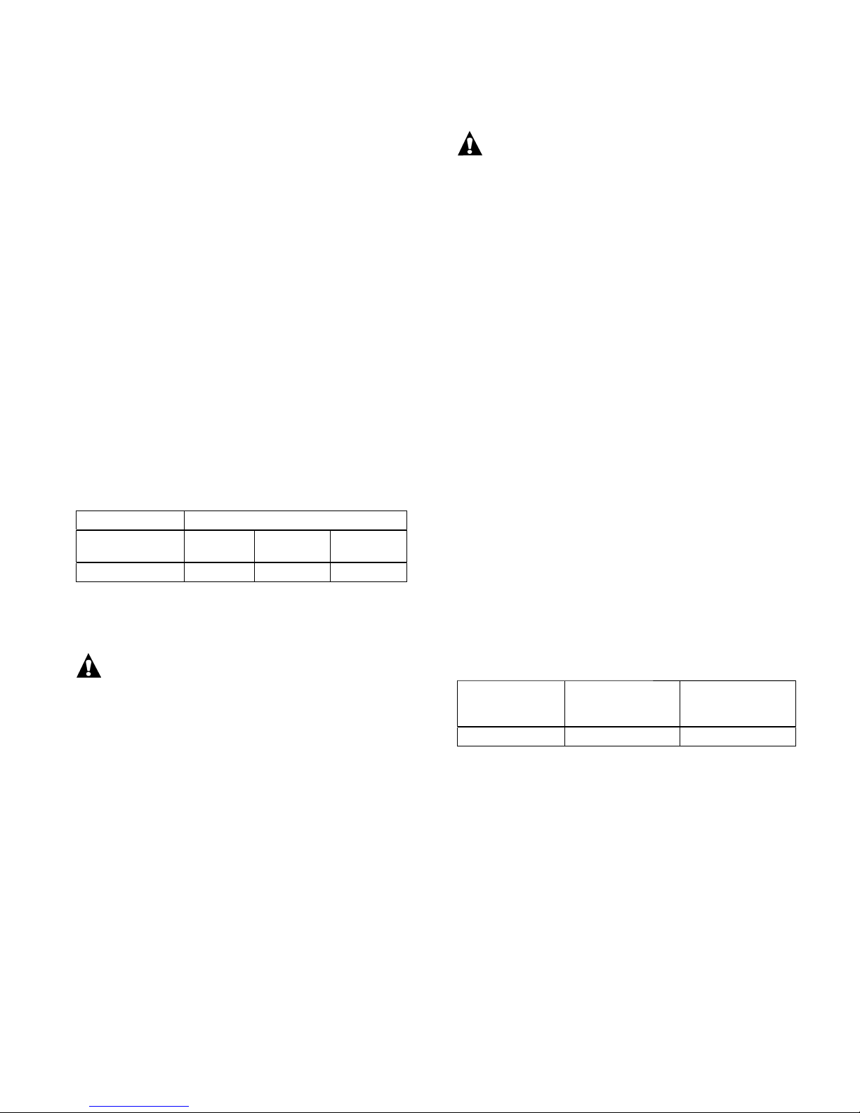
The correct initial charge rate will vary due to
numerous factors, it should be approximately 25
amperes.
INITIAL CHARGE RATE
Charger Current
Rating
25 18 25 29.5
(-18%) Rating
Maximum
(+18%)
If the ammeter reads 30 amperes after 30
minutes, turn the charger off by first disconnecting
the AC plug from its recept acle.
CAUTION: TO PREVENT OVERHEATING AND
TRANSFORMER DAMAGE TO THE CHARGER, DO
NOT ALLOW THE CHARGER TO OPERATE FOR
MORE THAN 30 MINUTES WITH AMMETER
READING 30 AMPERES.
This high charge rate is caused if the charger is
connected to a battery pack with a system voltage
lower than specified on the charger. If battery
maintenance has recently been performed, check
to see if an individual battery has been connected
reverse polarity. Test by measuring the battery
system voltage with an accurate voltmete r at the
equipment battery connector.
If the batteries have been recently charged, the
battery is cold (temperature below 65°F) or the AC
input voltage is lower than nominal the initial
charge rate may only reach the minimum initial
charge rate at turn on for the specific current
rating charger.
If the initial charge rate is less than half of the
specified minimum initial charge rate at the
moment of turn on, the charger may be
malfunctioning due to electrical over load damage.
Turn the charger off by first disconnecting the AC
plug from its receptacle.
CAUTION: DO NOT USE THE CHARGER IF
THE OUTPUT IS LOW. BATTERIES WILL NOT
REACH FULL CHARGE, THEREBY INCREASING
THE POSSIBILITY OF A HARMFUL DEEP
DISCHARGE DURING THEIR NEXT USE.
This too low a charge rate at the instant of turn-on
can be due to a charger malfunction resulting from
electrical overload damage, or the battery pack
system voltage is higher than specified on the
charger. Test for the correct battery pack system
voltage with an accurate voltmeter at the
equipment battery connector. Check the fuse
assembly or individual fuses for an indication of
charger electrical overload damage. A blown
single fuse or single fuse link of the fuse assembly
indicates an electrical overload damage caused
short circuit failure of a rec tifie r diode.
DO NOT DISASSEMBLE THE CHARGER. Take
the charger to a qualified service agent to have
the heatsink assembly with diodes and correct
replacement fuse or fuse assembly installed.
Incorrect reassembly may result in a risk of
electric shock or fire.
During charge, the battery voltage gradually
increases which causes the charge rate to
decrease. Batteries able to deliver their full ra ted
capacity will still rise to 2.5 volts per cell, or higher,
at 80°F, as they reach maximum charge. Th is will
allow the charge current to decrease or taper to
the chargers designed finish charge rate or lower
at the end of charge. Refer to chart.
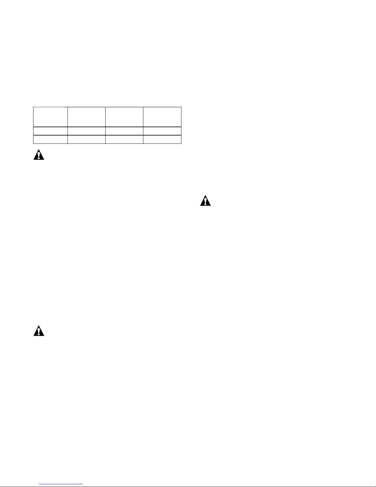
Charger
Current
Rating
25 amps 8 amps 10 amps or less
Finish Current
@2.5 Volts/Cell
@80
°F
Normal Finish
Charge Current
Range
Since each battery cell accepts charge at a
slightly different rate, charging with the ammeter
reading in the normal finish charge range for the
last few hours of charge is important to achieve
equalization of all battery cells every time the
batteries are charged.
As batteries wear out and lose capacity, th e end
of charge finish voltage continually decreases. As
the end of charge finish voltage decreases to less
than 2.5 volts per cell, this prevents the finish
charge current from decreasing to the normal
finish charge current range. The controller kit st ill
determines when the batteries have reached the ir
now reduced maximum charge capacity and will
turn the charger off.
www.lesterelectrical.com 3 00988J
Page 4
The major factors affecting the required charge
time are charger output current r ating, batter y size
or capacity in Amp-Hours, and how deeply the
battery is discharged. A larger, more deeply
discharged battery requires more time to recharge
to maximum charge with the same current rating
charger than a smaller, less deeply discharged
battery.
Use this table as a basic guide for charging time.
Charger
Current
Rating
25 amp 185 9 hours 3 hours
Battery
Capacity
20 Hr. Rate
305 14 hours 4 hours
Normal
Recharge
Time
Additional
Charge
Time
WARNING: DO NOT LEAVE THE CHARGER
DC OUTPUT CONNECTOR CONNECTED TO THE
BATTERY CONNECTOR WHILE UNATTENDED
FOR TWO DAYS OR MORE IN A ROW. SEVERE
OVERCHARGING AND POSSIBLE DAMAGE TO
THE BATTERIES WILL RESULT IF THE CHARGER
SHOULD FAIL TO TURN OFF.
Newer or colder batteries require greater energy
return, are slower to respond and consequently
require extended charge time at a low finish
charge current rate to return to maximum charge.
As batteries wear out and lose capacity, their
temperature rise both from use and on charge
becomes significant as an indicator of the end of
life and the battery cannot benefit from extended
charge time. Even though they are properly
charged, older batteries continually lose capacity,
and should be replaced when they will no longer
perform as desired.
4. After the charger has turned off, disconnect the
charger DC output connector from the battery
connector by grasping the plug body or handle
and pulling the plug straight out of the receptacle.
WARNING: TO AVOID DAMAGE TO THE
CHARGER CORD, CONNECTOR PLUG, AND
BATTERY CONNECTOR RECEPTACLE, DO NOT
PULL ON THE CHARGER CORD. DO NOT TWIST,
ROCK, OR PULL THE CONNECTOR PLUG
SIDEWAYS.
ON-DEMAND CHARGING
Battery cycle life is directly determined by severity of
use. A battery that has 100% of its available energy
discharged every time it is used will wear out twice as
fast as a battery that has 70% of its available energy
discharged every time it is used. In severe use
situations, some additional battery life can be realized
by instituting short charge periods during work bre aks.
This reduces the incidence of full 100% battery
depletion before charging.
Follow "Normal Operation" procedures to begin a
short charge period. At the end of any short charge
period where the charger has not turned off, turn the
charger off by first disconnecting the AC power supply
cord or pressing the "Manual Stop" button if the
charger is so equipped.
WARNING: DO NOT DISCONNECT THE DC
OUTPUT CONNECTOR FROM THE BATTERY
RECEPTACLE WHEN THE CHARGER IS
OPERATING. THE RESULTING ARCING AND
BURNING OF THE PLUG AND RECEPTACLE
COULD CAUSE THE BATTERIES TO EXPLODE.
If the charger must be stopped, first disconnect the AC
power supply cord from its outlet, or depress the
"Manual Stop" button if the charger is so equipped.
Only after the charger has turned off, then disconne ct
the charger DC output plug from the battery
receptacle.
BATTERY STORAGE MAINTENANCE
When the equipment is not in use, charge the
batteries once each week. Remove the DC output
connector at the end of charge.
www.lesterelectrical.com 4 00988J
Page 5
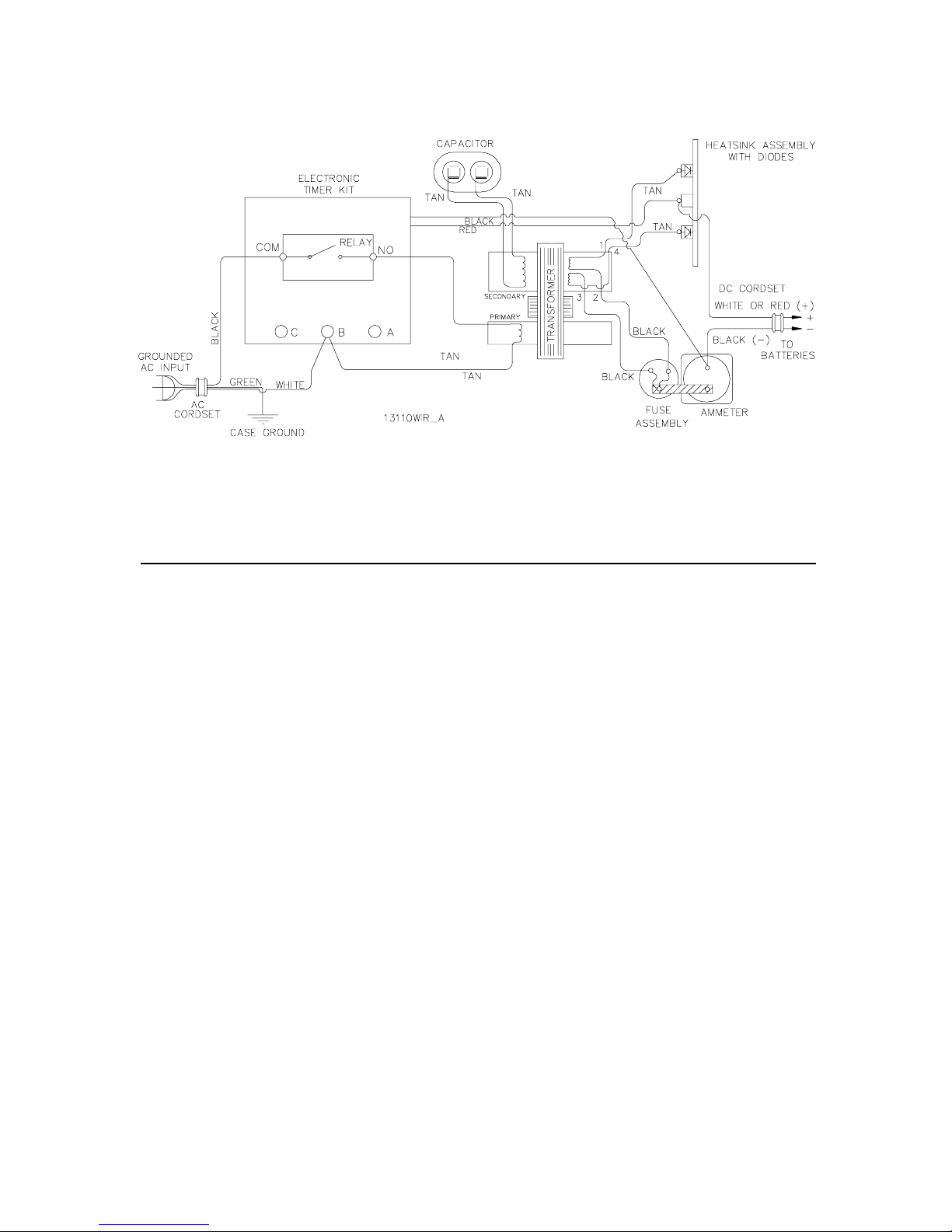
WIRING DIAGRAM
PARTS LIST FOR LESTRONIC II CHARGER
MODEL 13110 TYPE 24LC25-8ET
115 VAC / 60 HZ
PART NO.
QTY.
DESCRIPTION
15114S 1 CASE ASSEMBLY
13145S 1 TRANSFORMER ASSEMBLY
16354S 1 HEATSINK ASSEMBLY, W/ DIODES
04127S 1 AMMETER
24920S 1 ELECTRONIC TIMER ASSEMBLY
* 04483S 1 RELAY, FOR TIMER ASSEMBLY
** 23385S 1 RELAY, FOR TIMER ASSEMBLY
02390S 1 CAPACITOR, 6.0 MFD, 660 VAC
08776S 1 FUSE ASSEMBLY
02028S 1 BUSHING, 7W-2, INSULATOR FOR DC CORD
03894S 1 BUSHING, 7K-2, INSULATOR FOR AC CORD
11923S 1 CORDSET, AC, 14/3, 80”, MOLDED PLUG
33014S 1 CORDSET, AC, 14/3, 248”, MOLDED PLUG
08020S 1 CORDSET, DC, 12/2, W/ LESTER PLUG
12227S 1 CORDSET, DC, 12/2, W/ RED 50 AMP ANDERSON
08607S 1 CORDSET, DC, 12/2, W/ GRAY 5 0 AM P ANDERSO N
12284S 1 CORDSET, DC, 12/2, W/ RED 175 AMP ANDERSON
08224S 1 CORDSET, DC, 12/2, W/ GRAY 1 75 A MP ANDERS ON
18413S 1 CORDSET, DC, 10/2, W/ GRAY 5 0 AM P ANDERSO N
08313S 1 PLUG ASSEMBLY, DC, GRAY 50 AMP ANDERSON PLUG
12302S 1 PLUG ASSEMBLY, DC, RED 50 AMP ANDERSON PLUG
02957S 1 PLUG ASSEMBLY, DC, 175 AMP ANDERSON PLUG
* FOR USE WITH CHARGERS BUILT BEFORE 47/03
** FOR USE WITH CHARGERS BUILT AFTER 47/03
www.lesterelectrical.com 5 00988J
Page 6

LIMITED WARRANTY
Lester Electrical warrants each new Lester Battery Charger for defects in material and workmanship for a period
of two (2) years from the date of manufacture of the complete unit.
Repairs can be made at the Lester Electrical factory. To do so, FIRST obtain a "Return Material Authorization"
number by calling the Service Department of Lester Electrical (402 477-8988) or by e-mailing
[email protected] and send the defective unit with transportation charges prepaid to:
Lester Electrical
625 West A Street
Lincoln, NE 68522-1794 USA
Attention: Service Department
RMA #
For repairs made at other than the Lester Electrical factory, Lester will provide only the replacement parts.
Defective parts should be sent with transportation charges prepaid to the Lester Electrical factory at the address
noted above.
If the unit or parts are found, in the reasonable judgment of Lester Electrical, to be defective in material or
workmanship, repair, or replacement will be made by Lester Electrical without charge for parts or labor.
Repair or replacement will be at the discretion of Lester Electrical, with replacements being made using
current models or parts performing the equivalent function. Labor charges other than those incurred at
the Lester Electrical factory are not covered under this warranty. All expenses associated with delivering
defective items to the Lester Electrical factory and the expense of returning repaired or replaced items
from the Lester Electrical factory to the owner will be paid for by the owner. All warranty work
accomplished at the Lester Electrical factory will be completed within a reasonable time after receipt of
defective items.
This warranty does not cover any semiconductor parts, such as diodes, which are vulnerable to electrical
overloads beyond the control of Lester Electrical. Warranty on parts not manufactured by Lester Electrical, which
include, but are not limited to, timers and ammeters is limited to the period specified in the original manufacturer's
warranty.
This warranty does not cover any charger that has been subject to misuse, neglect, negligence, or accident, or
operated in any way contrary to instructions specified on the charger case and in the owner's manual. No claim of
breach of warranty shall be cause for cancellation of the contract of sale of any Lester Electrical charger. Lester
Electrical assumes no responsibility for loss of time, inconvenience, or other damage, consequentia l or otherwise,
resulting from a defective charger. All implied warranties (including merchantability) are limited in duration t o two
(2) years from date of manufacture warranty period.
Some states do not allow the exclusion or limitation of incidental or consequential damages, or limitations on how
long an implied warranty lasts, so the above limitations may not apply to you. This warranty gives you specific
legal rights, and you may also have other rights which vary from state to state.
Lester Electrical's obligation under this warranty is strictly and exclusively limited to the repair or replacement of
defective items. Lester Electrical issues this warranty in good faith and with full confidence in the workmanship
and quality of Lester Electrical products.
www.lesterelectrical.com 6 00988J
 Loading...