

Page 1
Intalling Your Wireless Light Switch
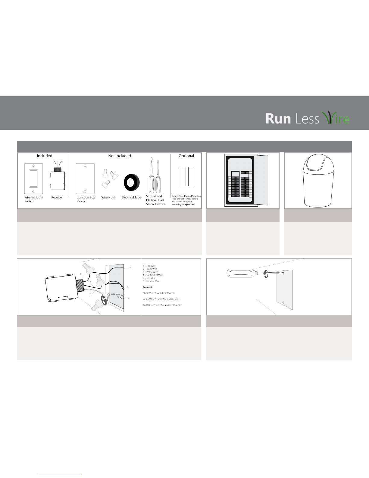
1. Before installation, verify that everything is included in your kit and that you have the items, listed above, ready
for use.
• Each kit includes a Single Rocker Self-Powered Light Switch, (1) ILLUMRA 3-wire Relay Receiver, (2) 6-32 x 3/4” phillips athead self tapping screws, (2) 6 x
3/8” phillips athead screws, (1) Faceplate w/ screws, (1) Installation Guide.
• If the receiver will be installed in an existing light switch junction box, you will need a junction box cover to cover the receiver and box.
• Wire nuts and electrical tape are required to secure the connection between the light xture wires and the receiver wires.
• Depending on where and how you install the wireless light switch, double-sided tape or wall screws will be required to secure the light switch to the wall.
2. Turn o the power to the switch
through the breaker.
WARNING: To avoid risk of re, shock, or death, TURN OFF
POWER at circuit breaker or fuse and verify that it is OFF
before installation begins. Make sure that it remains OFF
until installation is complete. Please be aware that with some
versions of the product, it is possible to have multiple branch
circuits feeding the Relay Receiver.
3. Remove old light switch from
junction box and dispose
Our Wireless Switch Kit is designed to last up to 20 years
and can be used in multiple homes. erefore, step three
may be replaced by saving your old light switch to put
back if you plan on moving your wireless light switch to
your new home.
4. Connect receiver wires to the existing wires in the junction box.
• e hot wire will be black and the neutral wire will be white.
• If no neutral wire is available in the switch junction box, you will need to wire the receiver into the junciton box of the light xture.
• Use wire nuts and electrical tape to connect the wires.
• Wiring Diagram is on the back of this installation guide.
SAFETY NOTE - If your xture is a ceiling-hugger xture, use only compact ourescent bulbs to avoid overheating. Also, if you are unsure about the wiring,
contact a local electrician.
5. Cover junction box with face plate.
Covering the junction box aer installing the receiver will reduce the risk of injury, re, and electrical failure. DO NOT cover
the junction box with drywall and paint as you may need to access the receiver in the future.
Single Rocker Switch and 3-Wire Receiver
Page 2
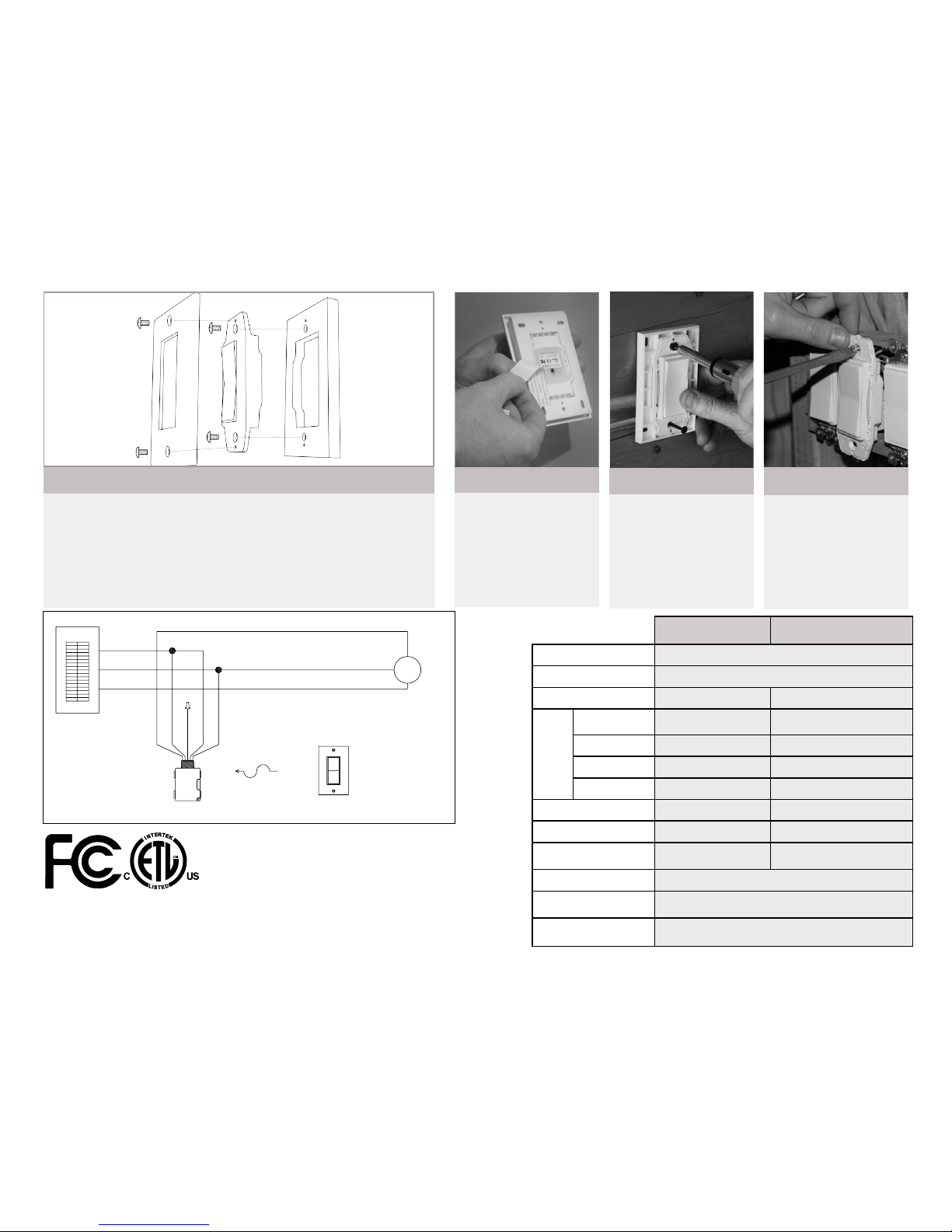
6. (c) Switch box mount
Step 1: Set aside the Back Plate. It is not
needed for this installation.
Step 2: Attach the switch into the screw
holes on the switch box using the 6-32 x 3/4”
machine screws.
Step 3: Attach the faceplate aer the switch
has been attached to the switch box (Faceplate
screws are included).
6. (b) Screw Surface Mount
Step 1: If necessary, drill pilot holes into
the wall.
Step 2: Use suitable screws (not included) to
mount the wireless light switch to the wall.
Step 3: Attach the Switch to the Back Plate
using the included 6 x 3/8” screws.
Step 4: Attach the faceplate aer the switch
has been attached to the wall (Faceplate screws
are included).
6. (a) Adhesive Surface Mount
Step 1: Attach the switch to the Back Plate
using the included 6 x 3/8” screws.
Step 2: Attach the faceplate to the switch and
back plate assembly (Faceplate
screws are included).
Step 3: Apply adhesive tape to the Back Plate
of the switch.
Step 4: Ax the switch to the wall.
6. (a) Assemble the lightswitch based on the location and mouting method.
Wireless light switches can be mounted in a standard switch box or surface mounted using screws or adhesive. If mounting to junc-
tion box, remove backplate from light switch assembly. e light switch face plate should be ush with the wall. Ensure that the light
switch location os no more than 50-150 feet from the receiver. Consider testing the range before installation.
3-Wire Relay Receiver
Single-rocker Self Powered
Switch
Range
50 - 150 feet (typical)
Frequency
315 MHz
Relay Output
24 VAC N/A
Max
Loads/
Contact
Ratings
Tungsten / Incan-
descent
100 W N/A
Fluorescent Ballast
3 A N/A
General Duty
6 A
N/A
A300 Pilot Duty
24 VA N/A
Power Supply
24 VAC - 50/60 Hz Self-Powered when Pressed
Dimensions
2.11 x 1.73 x 1.09 inches
2.75(W) x 4.5(H) x 0.62(D) inches
Operating Temperature
14° to +122°F (-10° to
+50°C)
-13° to +149°F (- 25 ° to + 65°C)
Storage Temperature
-4° to +176°F (-20° to +80°C)
Radio Certication
FCC (United States): SZV-TCM2XXC
I.C. (Canada): 5713A-TCM2XXC
Safet Approval
ETL (United States): UL244A, UL2043
ETL(Canada): CSAc22.2#14-05
Contains FCC ID: SZV-TCM2XXC Contains IC: 5713A-TCM2XXC e enclosed device
complies with Part 15 of the FCC Rules. Operation is subject to the following two conditions: (i)
this device may not cause harmful interference and (ii.) this device must accept any interference
received, including interference that may cause undesired operation.
ETL (US) – Conforms to UL STD 244A. is device was tested according to and was found to
comply with UL 244A Solid State Controls for Appliances and UL 2043 UL Standard for Safety
Fire Test for Heat and Visible Smoke Release for Discrete Products and eir Accessories Installed in Air-Handling Spaces.
ETL (Canada) – Certied to CAN/CSA STD C22.2 No. 14-05. is device was tested according to and was found to comply with CAN/CSA
STD C22.2 No. 14-05.
E3R-R12-5IBTP
BREAKER PANEL
HOT
NEUTRAL
GREEN OR BARE
WHITE
GROUND
BLACK
RED
N.O.
COMMON
YELLOW
BLUE
N.C.
AC POWER
AC POWER
WHITE
BLACK
GREEN OR BARE
AC POWER
WHITE
GROUND
FIXTURE
AC POWER
BLACK
BATTERY-FREE,
WIRELESS SWITCHES
WIRELESS
CONTROL
SIGNAL
UP TO
150 FT.
 Loading...