

Page 1
5
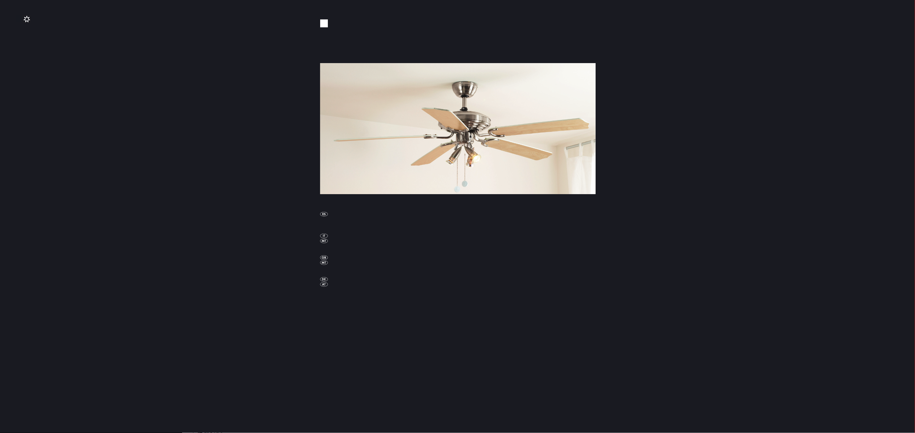
VENTILADOR DE TECHO
VENTILATORE A PALE
VENTILADOR DE TECHO
Instrucciones de uso
VENTILATORE A PALE
Istruzioni per l'uso
CEILING FAN
Operating instructions
DECKEN-VENTILATOR
Bedienungsanleitung
KH 1150
KOMPERNASS GMBH · BURGSTRASSE 21 · D-44867 BOCHUM
www.kompernass.com
ID-Nr.: KH1150-01/08-V1
Page 2
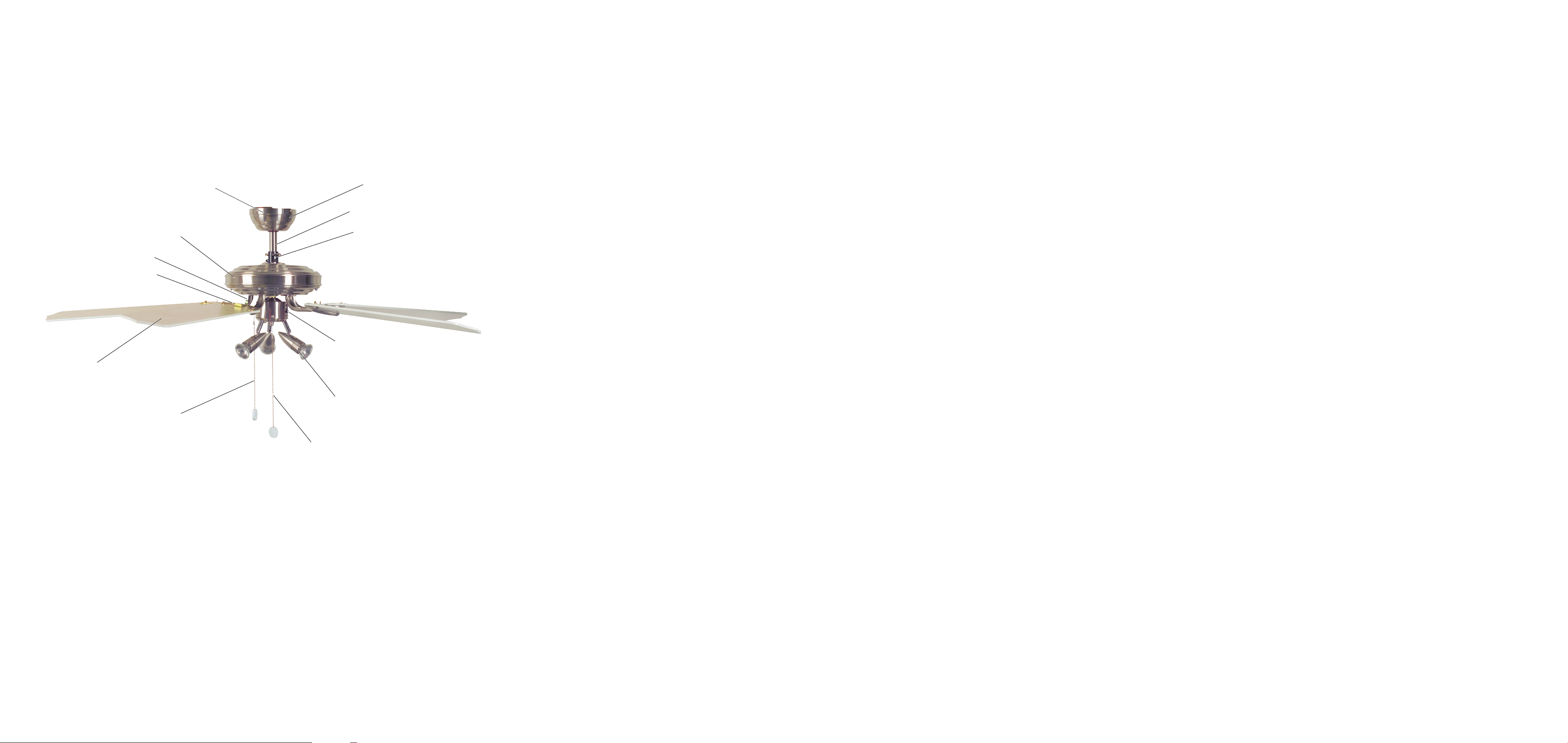
L
A
B
H
J
K
I
G
F
C
D
E
Page 3

ÍNDICE PÁGINA
1 Instrucciones de seguridad 2
2 Uso conforme al previsto 2
3 Generalidades del producto 2
4 Descripción del producto 2
5 Indicador de dirección 2
6 Montaje del ventilador de techo 3
6.1 Montaje de los soportes de las palas (J) . . . . . . . . . . . . . . . . . . . . . . . . . . . . . . . . . . . . . . . . . . . . . . . . . . . . . . . . . . . . . . . . . . . .3
6.2 Montaje de la barra de prolongación (B) . . . . . . . . . . . . . . . . . . . . . . . . . . . . . . . . . . . . . . . . . . . . . . . . . . . . . . . . . . . . . . . . . . .3
6.3 Montaje del módulo de luz (E) . . . . . . . . . . . . . . . . . . . . . . . . . . . . . . . . . . . . . . . . . . . . . . . . . . . . . . . . . . . . . . . . . . . . . . . . . . . .4
6.4 Retirada de las sujeciones de seguridad para el transporte . . . . . . . . . . . . . . . . . . . . . . . . . . . . . . . . . . . . . . . . . . . . . . . . . . . . .4
6.5 Montaje de las palas (H) . . . . . . . . . . . . . . . . . . . . . . . . . . . . . . . . . . . . . . . . . . . . . . . . . . . . . . . . . . . . . . . . . . . . . . . . . . . . . . . . .4
6.6 Colocación del ventilador . . . . . . . . . . . . . . . . . . . . . . . . . . . . . . . . . . . . . . . . . . . . . . . . . . . . . . . . . . . . . . . . . . . . . . . . . . . . . . . .4
7 Funcionamiento 6
7.1 Ajuste de la velocidad . . . . . . . . . . . . . . . . . . . . . . . . . . . . . . . . . . . . . . . . . . . . . . . . . . . . . . . . . . . . . . . . . . . . . . . . . . . . . . . . . .6
7.2 Selección del sentido de giro . . . . . . . . . . . . . . . . . . . . . . . . . . . . . . . . . . . . . . . . . . . . . . . . . . . . . . . . . . . . . . . . . . . . . . . . . . . . .6
8 Limpieza 6
9 Características técnicas 6
10 Volumen de suministro 6
11 Lista de fallos 7
12 Garantía y asistencia técnica 8
13 Importador 8
14 Eliminación y reciclaje 8
Lea atentamente este manual de instrucciones antes del primer uso y consérvelo para posteriores utilizaciones. Entréguelas en caso de traspasar el aparato
a terceros.
IMPORTANTE:
Respete las instrucciones de seguridad
Familiarícese con el montaje y el funcionamiento del ventilador antes de utilizarlo.
- 1 -
Page 4
1 Instrucciones de seguridad
Peligro:
¡Respete las siguientes instrucciones de seguridad!
De lo contrario existe riesgo de accidente.
Peligro de asfixia
• No debe utilizar el aparato en la misma estancia junto con un calefactor
o una estufa de gasóleo o de gas. Excepción: Que la extracción de humos
haya sido comprobada y autorizada por un especialista teniendo en
cuenta el funcionamiento del ventilador.
Peligro de descarga eléctrica!
• El aparato solamente puede ser conectado a una línea eléctrica con
toma de tierra debidamente instalada y con una tensión de red de
220 hasta 240 V~con 50 Hz por un técnico especializado.
No debe sumergir en líquidos o exponer a humedad el aparato, ni
tampoco utilizarlo a la intemperie. En caso de que penetrase líquido
en la carcasa corte la corriente del aparato, p. ej. desconectando el
fusible correspondiente o accionando el interruptor (posicionamiento
a cero) de la caja general de protección.
• No doble ni aprisione el cable de conexión.
• Si el cable de conexión o el aparato están dañados encomiende a personal
especializado que lo repare antes de utilizarlo de nuevo. No debe abrir
la carcasa del aparato. En este caso no estará protegido y perderá el
derecho a la garantía.
Peligro de incendio
• No deje nunca el aparato desatendido durante su funcionamiento.
• Nunca coloque el aparato cerca de fuentes de calor.
• Nunca conecte el aparato mediante un Dimmer (regulador de luminosidad).
Utilice para el cambio de velocidad únicamente la cadena prevista para
tales fines.
¡Peligro de lesiones!
• No permita utilizar el aparato a personas (incluidos los niños) cuyas
facultades físicas, sensoriales o mentales, así como su falta de conocimientos o de experiencia, les impida hacer un uso seguro del mismo
si no están bajo vigilancia o han sido instruidos correctamente.
• Vigile a los niños para asegurarse de que no juegan con el aparato.
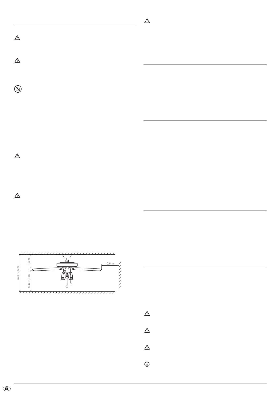
• La distancia mínima del extremo de las palas al suelo, una vez montado
el aparato, debe ser de 2,30 m. La separación entre las palas y el techo
debe ser como mínimo 0,30 m. La distancia lateral a las paredes u
obstáculos debe ser al menos de 0,60 m (ver fig. 1).
2 Uso conforme al previsto
El ventilador de techo sirve exclusivamente para la recirculación del aire
en una sala cerrada. Este ventilador de techo está indicado exclusivamente
para uso en viviendas privadas. Tenga en cuenta todas las informaciones
contenidas en estas Instrucciones de uso y de montaje, sobretodo las indicaciones de seguridad. Cualquier uso distinto no se considerará conforme
a lo previsto.
3 Generalidades del producto
A Cubierta protectora
B Barra de prolongación (2 variantes)
C Pieza de conexión
D Interruptor deslizante para el cambio de sentido de giro
E Módulo de luz con 3 lámparas (incl. 3 bombillas halógenas)
F Cadena de iluminación
G Cadena de cambio de velocidad
H Palas (5 piezas)
I Placas de fijación (5 piezas)
J Soporte de las palas (5 piezas)
K Carcasa del motor
L Placa de montaje
4 Descripción del producto
El ventilador de techo KH 1150 dispone de tres niveles de velocidad que
se regulan mediante una cadena. Un conmutador posibilita el cambio de
sentido de giro para hacer circular el aire bien hacia abajo, bien hacia
arriba. Adicionalmente el ventilador está equipado con una iluminación
que consta de 3 lámparas halógenas que se encienden o apagan mediante
una cadena independiente.
Fig. 1: Distancias mínimas del ventilador de techo
• No debe existir ningún obstáculo en el área de rotación del aparato.
• El aparato debe estar bien asegurado al techo de la estancia. El techo
de la sala, tacos y tornillos deben ser capaces de soportar los esfuerzos
adicionales originados por la rotación. Asesórese en su caso en una
tienda especializada de construcción acerca del ventilador de techos.
5 Indicador de dirección
El capítulo 6 describe el montaje y el capítulo 7 el funcionamiento básico
del ventilador de techo KH 1150.
Lea los capítulos atentamente para llevar a cabo un montaje sin dificultad
y sin fallos, y para comprender y poder cambiar las funciones.
Se utilizarán el siguiente vocabulario y símbolos:
PELIGRO
Advertencia acerca de posibles peligros graves e incluso mortales
ADVERTENCIA
Advertencia acerca de posibles heridas leves a personas o daños a objetos
CUIDADO
Advertencia acerca de posibles defectos o fallos del producto
IMPORTANTE/ INDICACIÓN
Aquí se hará una indicación importante o útil.
- 2 -
Page 5
6 Montaje del ventilador de techo
1
2
3
H
I
J
1
2
3
C
ADVERTENCIA:
¡Tenga en cuenta las indicaciones de seguridad (ver cap. 1), para evitar
lesiones o daños derivados de un montaje incorrecto! ¡No utilice el ventilador si
está defectuoso!
INDICACIÓN:
Las letras entre comillas hacen referencia a la figura del capítulo 3
"Vista general del producto".
Herramientas necesarias
1b Si quiere utilizar la barra de prolongación corta saque entonces el suporte
completamente de la barra larga y empuje un poco, tal como se muestra,
hasta la mitad de la barra corta.
Destornillador de estrella
Llave de boca de 8 mm
6.1 Montaje de los soportes de las palas (J)
1 Elegir la decoración deseada: madera o superficie blanca. Disponer las
palas de modo que la decoración elegida se encuentre hacia abajo.
2 Introducir los pernos de seguridad de un soporte (J) desde abajo a través
de los 3 orificios de un pala (H). Colocar las placas de sujeción (I) y
desplazarlas en el sentido de las flechas (ver fig.). La pinza elástica
debe encajarse de este modo y sujetar el perno central (ver fig.: círculo).
Montar todas las palas del mismo modo.
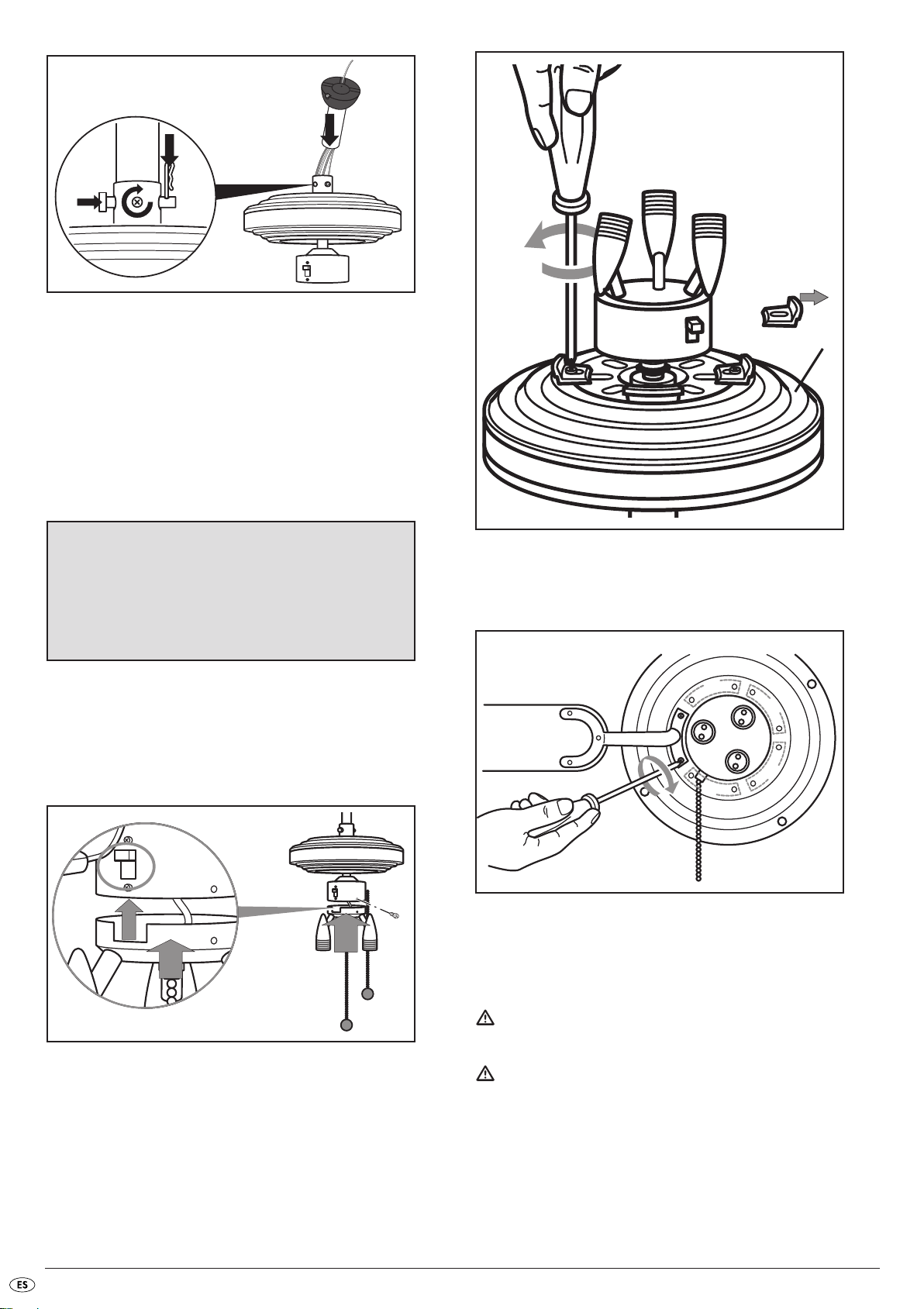
2 Paso 1: Aflojar el tornillo lateral de la pieza de conexión (C), para
poder colocar la barra de prolongación.
Paso 2: Desmontar el perno de la pieza de conexión: Sacar el
pasador de seguridad.
Paso 3: Retirar el perno.
PELIGRO:
Un cable dañado puede provocar cortocircuitos. ¡Si toca el ventilador en tal caso corre un grave peligro!
¡Al realizar las siguientes operaciones de montaje de los pernos
en la barra de prolongación y la pieza de conexión, preste
atención de no dañar el cable!
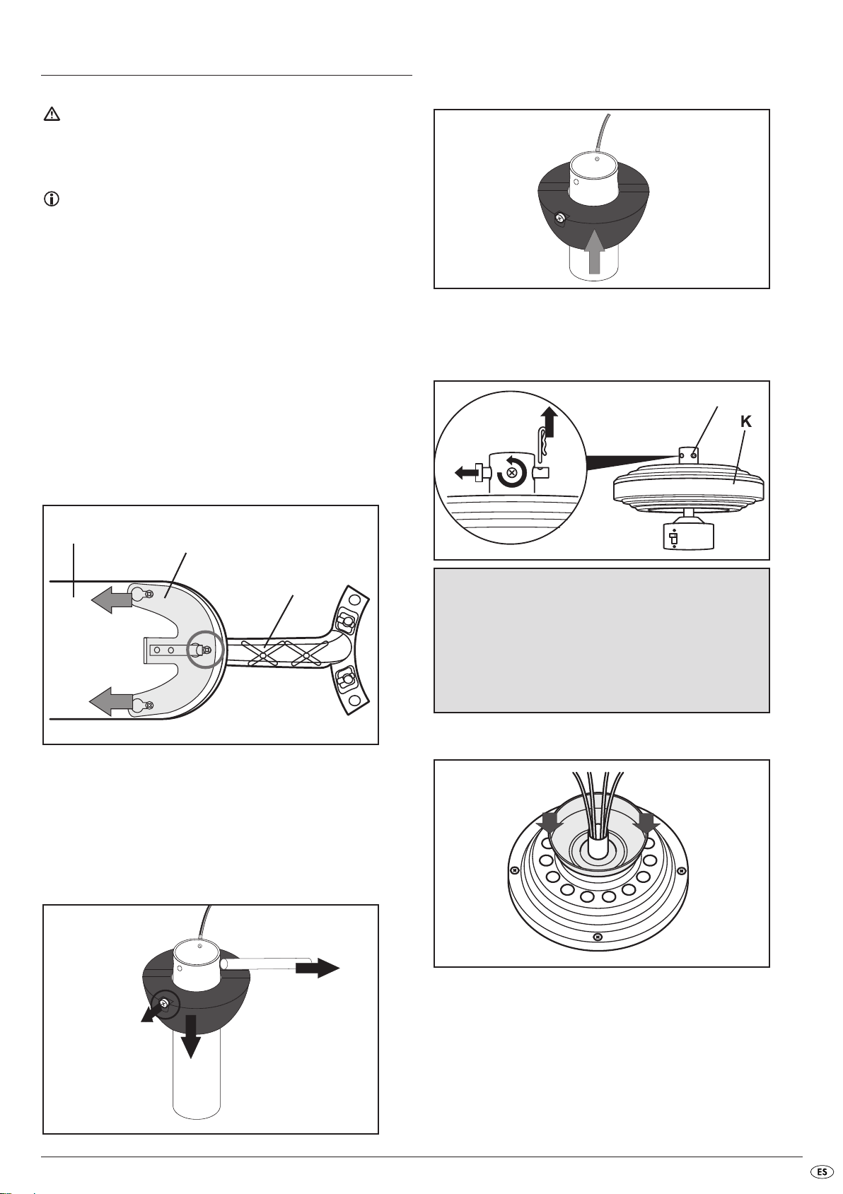
6.2 Montaje de la barra de prolongación (B)
1a Barra larga con soporte plástico:
Paso 1: Soltar el tornillo de seguridad lateral de la barra de prolongación
(ver fig., círculo).
Paso 2: Empujar el soporte hacia abajo hasta que se libere el perno de
seguridad.
Paso 3: Sacar el perno de seguridad.
3 Pasar el cable por la cubierta protectora y colocar la misma en la
carcasa del motor mediante la pieza de conexión.
4aPaso 1: Barra de prolongación larga: Pasar el cable y a continuación
colocar la barra de prolongación en la pieza de conexión.
Paso 2: Montar el perno de seguridad de la pieza de conexión.
Paso 3: Colocar el pasador de seguridad.
Paso 4: Primero girar a la vez con fuerza y simétricamente ambos tornillos
y después apretarlos bien con el destornillador. Apretar la tuerca
contra la pieza de conexión (contratuerca).
- 3 -
Page 6
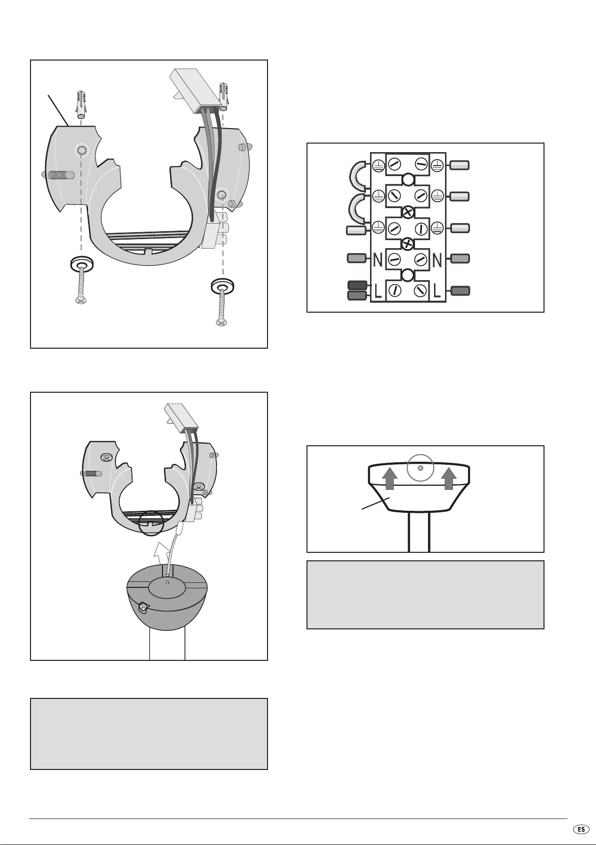
4b Barra de prolongación corta: Después de pasar el cable (v. 4a,
1
3
4
2
K
paso 1), realizar en primer lugar el siguiente paso de montaje 5.
A continuación, realizar los pasos 2 a 4 descritos en 4a.
5 Pasar los pernos por los orificios superiores de la barra de prolongación
y centrarlos.
Subir el soporte por los pernos prestando atención a que el tornillo de
seguridad quede ajustado en el hueco correspondiente. (comp. fig. paso 1a).
Enroscar el tornillo de seguridad en la rosca de la barra de prolongación.
6.3 Montaje del módulo de luz (E)
PELIGRO:
Un cable dañado puede provocar cortocircuitos. ¡Si toca el
ventilador en tal caso corre un grave peligro!
¡Colocar los cables en la carcasa de forma que no queden
pinzados cuando se monte el módulo de luz!
1 Retirar los tres tornillos con anillos elásticos del módulo de luz (E).
2 Unir el conector del cable del módulo de luz con la hembrilla al ventilador.
3 Colocar el módulo de luz en la carcasa del motor, teniendo en cuenta
que el hueco se encuentre debajo del interruptor de sentido de giro
(ver fig., círculo).
4 Apretar el módulo de luz con los 3 tornillos y los anillos elásticos.
6.5 Montaje de las palas (H)
1 Atornille las palas con 2 tornillos con arandelas a la carcasa del motor
(ver fig.).
6.4 Retirada de las sujeciones de seguridad para el
transporte
1 Aflojar los 3 tornillos de las sujeciones de seguridad para el transporte
que hay en la carcasa del motor (K).
2 Retire los tornillos con los aros elásticos así como las sujeciones de segu-
ridad.
3 Guarde las sujeciones de seguridad junto con los tornillos y los aros elásticos
por si necesita realizar un transporte posterior.
2 Gire lentamente el ventilador varias vueltas para comprobar si las palas
están montadas correctamente. Si el ventilador no gira suavemente revise
el atornillado de las palas.
6.6 Colocación del ventilador
PELIGRO:
Debe asegurarse de que la línea de conexión eléctrica está desconectada.
ADVERTENCIA:
El techo de la sala así como el atornillado debe poder soportar un peso
de al menos 28 kg.
Utilice tornillos de 8 x 50 mm con tacos.
Para la fijación a falsos techos (p. ej. placas de yeso) utilice tacos especiales
para este fin. Alternativamente averigüe si la placa de montaje se puede
asegurar a este tipo de construcción (resistente) (madera cuadrada, vigas)
y utilice tornillos de madera.
- 4 -
Page 7
1 Asegurar bien la placa de montaje (L) al techo con 2 tornillos y en caso
L
“KLICK”
A
(I)
(II)
(III)
1
2
3
necesario con tacos.
Compruebe la capacidad de carga del atornillado.
Indicación de colores:
Verde-Amarillo (I): Conductor de protección a tierra
Azul (II): Conductor neutro
Marrón (III): Conductor de corriente activo (también: negro)
Conectar la línea de corriente
Paso 1: Conectar el cable de puesta a tierra a la regleta (I).
Paso 2: Conectar el conductor azul (N) (II).
Paso 3: Conectar el conductor marrón (L) (III).
2 Colocar el ventilador en la placa de montaje, teniendo en cuenta
la muesca del soporte (ver fig., círculo).
Enchufar el conector
Enchufe ambos conectores de los dos conductores de puesta a tierra con
la hembrilla a la placa de montaje.
Enchufe a continuación el conector de cable ancho del ventilador con la
hembrilla a la placa de montaje.
4 Engatillar la cubierta (A) protectora en la placa de montaje: colocarla
en las esferas que se encuentran juntas y engatillar las esferas elásticas
opuestas (¡clic!).
INDICACIÓN:
Procure no tocar las lámparas halógenas con los dedos. A la
hora de colocarlas utilice un trapo limpio o p.ej. guantes de tela.
3 Conectar la toma de corriente.
PELIGRO:
¡La conexión a la corriente eléctrica sólo debe hacerse por
personal especializado!
¡Si no se presta atención existe peligro de descarga eléctrica!
5 Montar las lámparas halógenas en el portalámparas: Coloque las lámparas
halógenas en los huecos redondos presionando ligeramente y ajústelas
girando en el sentido de las agujas del reloj.
6 Conectar la alimentación de corriente.
- 5 -
Page 8

7 Funcionamiento
8 Limpieza
7.1 Ajuste de la velocidad
Ajuste el nivel de velocidad con la cadena (G) en la carcasa del motor.
Cada vez que tire de ella cambiará la velocidad con la siguiente secuencia:
rápido - medio - lento - OFF
Encienda la luz con la cadena central (F).
Cuando se enciende o apaga el ventilador con un interruptor adicional o
un fusible, al no apagarlo con la cadena, volverá a funcionar con la última
velocidad que se utilizó.
7.2 Selección del sentido de giro
INFORMACIÓN: Sentido de giro
El ventilador gira en sentido contrario a las agujas del reloj:
Función clásica del ventilador. La corriente de aire expulsada hacia abajo
causa un efecto refrigerante. Utilización principalmente para las estaciones
cálidas.
El ventilador gira en sentido de las agujas del reloj:
La corriente de aire se dirige hacia el techo. El aire caliente existente se
distribuye mejor por la sala y evita que el calor se acumule en el techo.
PRECAUCIÓN:
Accione el interruptor de sentido de giro únicamente cuando el ventilador
esté parado para que el ventilador no se dañe.
PELIGRO:
Desconecte el ventilador de la corriente eléctrica antes de limpiarlo: Desconecte el fusible correspondiente. ¡Al tocar cables o piezas conectados
a la corriente eléctrica corre un gran peligro!
Limpie el ventilador con un trapo suave, que puede humedecer un poco
para eliminar la suciedad más persistente. No utilice ningún disolvente,
ningún limpiador ni medio agresivo, p.ej. esponjas o cepillos abrasivos
con el fin de no arañar el ventilador.
9 Características técnicas
Producto Ventilador de techo KH 1150
Tensión de red 220 - 240 V~, 50 Hz
Potencia nominal del
ventilador 60 W
Luz 3 x máx. 50 W GU10
Materiales Metal y MDF
Dimensiones 131 x 40 cm
(35 cm con la barra de prolongación corta)
Peso (incl.) 6750 g
Identificado con
marcas de control CE, GS
Cambie el sentido de giro con el interruptor deslizante.
Para ello sepa que:
Interruptor arriba: El ventilador gira en el sentido de las agujas del reloj.
Interruptor abajo: El ventilador gira en sentido contrario a las agujas
del reloj. (visto desde abajo)
10 Volumen de suministro
1x motor en la carcasa
1x módulo de luz con portalámparas
5x palas
5x soportes de las palas
1x fijación de techo con cubierta
1x barra de prolongación
3x bombillas 50 W GU10
Tornillos y tacos
Vídeo de instalación (SVCD)
Manual de instrucciones
- 6 -
Page 9
11 Lista de fallos
Problema/Fallo
Los tornillos de fijación no se pueden
apretar o se pasaron de rosca durante el
montaje
El ventilador no se pone en marcha Los fusibles están defectuosos Comprobar los fusibles y cambiarlos en
El interruptor de sentido de giro está en el
centro
El interruptor de cadena está en la posición
"OFF"
El enchufe está suelto
El ventilador está averiado Encargar la revisión del ventilador a un
El ventilador hace mucho ruido o tiembla
mucho
El soporte de las palas no está bien sujeto Comprobar el atornillado del soporte de
Las palas están dañadas
Pala no equilibrada Cambie el orden de las palas entre sí
Posible/s causa(s) Solución
Cambiar los tornillos y las tuercas Utilizar
sólo tornillos que se correspondan con los
tornillos originales o pida información al
fabricante o vendedor.
caso necesario
Cambiar el interruptor de sentido de giro
hacia la posición arriba o abajo
Tirar de la cadena 1 vez
PELIGRO:
Desconecte el ventilador de la corriente
antes de revisar el enchufe. Revise el enchufe
técnico o enviarlo al servicio de asistencia
técnica (véase la dirección en el capítulo
"Garantía y asistencia técnica")
las palas
Revisar las palas y cambiarlas en caso
necesario
Las placas de fijación están sueltas Comprobar las placas de fijación
Colocación incorrecta
PELIGRO:
Desconecte el ventilador de la corriente
antes de revisar si está bien colocado.
Compruebe la correcta sujeción de la
placa de montaje y de la barra de prolongación y corríjalas en caso necesario
La luz no funciona Las bombillas están defectuosas Compruebe las lámparas halógenas y
cambie las bombillas defectuosas
El enchufe está suelto
PELIGRO:
Desconecte el ventilador de la corriente
antes de revisar el enchufe. Revise el enchufe.
¡No llevar a cabo ninguna manipulación del producto!
Las reparaciones de piezas importantes para la seguridad sólo debe llevarlas a cabo personal especializado.
- 7 -
Page 10
12 Garantía y asistencia técnica
Con este aparato recibe usted 3 años de garantía desde la fecha de compra.
El aparato ha sido fabricado cuidadosamente y ha sido probado antes de
su entrega. Guarde el comprobante de caja como justificante de compra.
Si necesitara hacer uso de la garantía, póngase en contacto por teléfono
con su punto de servicio habitual. Éste es el único modo de garantizar un
envío gratuito.
La garantía cubre los defectos de fabricación o del material, pero no las
piezas sujetas a desgaste y los daños sufridos por las piezas frágiles (p. ej.
el interruptor o las pilas). El producto ha sido diseñado únicamente para
el uso privado y no para el uso comercial.
En caso de un tratamiento inadecuado e indebido, uso de la fuerza bruta
e intervenciones por asistencia técnica distinta a la autorizada por nosotros, se
extinguirá la garantía. Esta garantía no reduce en forma alguna sus derechos
legales.
Kompernass Service España
C/Invención 7
Polígono Industrial Los Olivos
28906 Getafe – Madrid
Tel.: 902/430758
Fax: 91/6652551
e-mail: support.es@kompernass.com
13 Importador
KOMPERNASS GMBH
BURGSTRASSE 21
D-44867 BOCHUM
www.kompernass.com
14 Eliminación y reciclaje
En ningún caso deberá tirar el aparato a la basura doméstica.
Este producto está sujeto a la normativa europea 2002/96/CE.
Evacúe el aparato en un centro de evacuación autorizado a través de las
instalaciones de evacuación comunitarias.
Tenga en cuenta las normativas actuales en vigor.
En caso de dudas póngase en contacto con su centro de evacuación.
El material de embalaje debe desecharse de forma respetuosa con
el medio ambiente.
- 8 -
Page 11
INDICE PAGINA
1 Indicazioni di sicurezza 10
2 Utilizzo conforme alla destinazione 10
3 Panoramica del prodotto 10
4 Descrizione del prodotto 10
5 Legenda 10
6 Montaggio del ventilatore a soffitto 11
6.1 Montaggio delle pale del ventilatore (J) . . . . . . . . . . . . . . . . . . . . . . . . . . . . . . . . . . . . . . . . . . . . . . . . . . . . . . . . . . . . . . . . . . . .11
6.2 Montaggio della barra di prolunga (B) . . . . . . . . . . . . . . . . . . . . . . . . . . . . . . . . . . . . . . . . . . . . . . . . . . . . . . . . . . . . . . . . . . . .11
6.3 Montaggio del corpo illuminante (E) . . . . . . . . . . . . . . . . . . . . . . . . . . . . . . . . . . . . . . . . . . . . . . . . . . . . . . . . . . . . . . . . . . . . . .12
6.4 Rimozione degli elementi di fissaggio per il trasporto . . . . . . . . . . . . . . . . . . . . . . . . . . . . . . . . . . . . . . . . . . . . . . . . . . . . . . . . .12
6.5 Montaggio delle pale . . . . . . . . . . . . . . . . . . . . . . . . . . . . . . . . . . . . . . . . . . . . . . . . . . . . . . . . . . . . . . . . . . . . . . . . . . . . . . . . . .12
6.6 Sospensione del ventilatore . . . . . . . . . . . . . . . . . . . . . . . . . . . . . . . . . . . . . . . . . . . . . . . . . . . . . . . . . . . . . . . . . . . . . . . . . . . . . .12
7 Comandi 14
7.1 Regolazione della velocità . . . . . . . . . . . . . . . . . . . . . . . . . . . . . . . . . . . . . . . . . . . . . . . . . . . . . . . . . . . . . . . . . . . . . . . . . . . . . .14
7.2 Selezione della direzione di rotazione . . . . . . . . . . . . . . . . . . . . . . . . . . . . . . . . . . . . . . . . . . . . . . . . . . . . . . . . . . . . . . . . . . . . .14
8 Pulizia 14
9 Dati tecnici 14
10 Volume della fornitura 14
11 Lista dei difetti 15
12 Garanzia e assistenza 16
13 Importatore 16
14 Smaltimento 16
Leggere attentamente le istruzioni per l'uso prima del primo utilizzo e conservarle per il successivo impiego. In caso di cessione dell'apparecchio a terzi,
consegnare anche le istruzioni.
IMPORTANTE:
Leggere attentamente e seguire accuratamente le indicazioni di sicurezza!
Imparare bene le istruzioni di montaggio e i comandi, prima di utilizzare il ventilatore.
- 9 -
Page 12

1 Indicazioni di sicurezza
PERICOLO:
rispettare e applicare le seguenti indicazioni di sicurezza!
In caso contrario, sussiste un rilevante rischio di infortunio.
Pericolo di soffocamento
• L'apparecchio non dev'essere utilizzato in concomitanza alla stufa o ele-
mento di riscaldamento a cherosene o a gas nello stesso ambiente.
Eccezione: la canna fumaria è stata collaudata e approvata da personale
specializzato, tenendo conto della presenza del ventilatore.
Pericolo di scossa elettrica!
• Solo un elettricista professionista può collegare l'apparecchio a un impianto
di rete elettrica installato a norma e dotato di messa a terra, con tensione
di rete di 220 - 240 V~e 50 Hz.
Non immergere mai l'apparecchio in liquidi, non esporlo a umidità e
non usarlo all'aperto. In caso di penetrazione di liquidi nell'alloggiamento dell'apparecchio, scollegarlo dalla rete elettrica, ad esempio
rimuovendo il fusibile domestico o azionando il tasto di interruzione
dell'alimentazione elettrica dall'apposito contatore (posizione O).
• Non piegare né schiacciare il cavo di alimentazione alla rete.
• Se il cavo di alimentazione o l'alloggiamento dell'apparecchio sono
danneggiati, l'apparecchio dev'essere riparato da personale specializzato
prima di un ulteriore utilizzo. Non aprire l'alloggiamento dell'apparecchio.
Aprendolo ci si espone a pericoli e la garanzia decade
Pericolo d'incendio
• Non lasciare mai l'apparecchio incustodito durante l'uso.
• Non sospendere mai l'apparecchio in vicinanza di fonti di calore.
• Non collegare il ventilatore a soffitto attraverso un regolatore luminoso.
Per modificare il numero di giri usare solo la catena di trazione prevista
allo scopo.
Pericolo di ferimento
•Questo apparecchio non è indicato per l'uso da parte di persone (inclusi
bambini) con limitate capacità fisiche, sensoriali o mentali o prive dell'esperienza e/o della conoscenza necessaria, a meno che tali persone
non vengano sorvegliate da un responsabile per la sicurezza o abbiano
ricevuto indicazioni sull'impiego dell'apparecchio.
• Sorvegliare i bambini per assicurarsi che non giochino con l'apparecchio.
• La distanza minima delle punte delle pale dal pavimento dopo il mon-
taggio dev'essere pari a 2,30 m. La distanza tra pale e soffitto deve essere di almeno 0,30 m. La distanza laterale dalle pareti o da eventuali
ostacoli dev'essere di almeno 0,60 m (v. ill. 1).
2 Utilizzo conforme alla destinazione
Il ventilatore serve esclusivamente alla movimentazione dell'aria in ambienti
chiusi. Questo ventilatore a soffitto è destinato esclusivamente all'utilizzo in
ambienti domestici privati. Attenersi a tutte le informazioni contenute nelle
presenti istruzioni di montaggio e d'uso, e soprattutto alle indicazioni di
sicurezza. Ogni altro utilizzo non è conforme alla destinazione.
3 Panoramica del prodotto
A Rivestimento
B Barra di prolunga (2 varianti)
C Pezzo di raccordo
D Interruttore a slitta per modificare la direzione di rotazione
E Corpo illuminante a 3 lampade (incl. 3 lampadine alogene)
F Catena per l'illuminazione
G Catena per modificare la velocità
H Pale (5 pezzi)
I Piastra di fissaggio (5 pezzi)
J Supporto pale (5 pezzi)
K Alloggiamento del motorino
L Piastra di montaggio
4 Descrizione del prodotto
Il ventilatore a soffitto KH 1150 dispone di tre livelli di velocità regolabili
attraverso una catena. Un interruttore permette la modifica della direzione
di rotazione, in modo da dirigere l'aria verso il basso o verso l'alto. Inoltre,
il ventilatore è provvisto di un corpo illuminante con 3 lampadine alogene,
che possono essere accese o spente attraverso un'altra catena.
5 Legenda
Ill. 1: distanza minima del ventilatore a soffitto
• Non devono essere presenti ostacoli nell'area di rotazione dell'apparecchio.
• L'apparecchio dev'essere saldamente fissato al soffitto. Il soffitto, i tasselli
e le viti devono poter sopportare il carico ulteriore dovuto alla rotazione
dell'apparecchio. Si consiglia di chiedere informazioni presso un centro
specializzato riguardo al fissaggio del ventilatore da soffitto.
Il capitolo 6 descrive il montaggio e il capitolo 7 i comandi principali del
ventilatore a soffitto KH 1150.
Leggere il capitolo attentamente per eseguire il montaggio in modo scorrevole
e senza errori, nonché per comprendere e realizzare le varie funzioni.
Vengono utilizzati i seguenti termini e simboli:
PERICOLO
avvertenza relativa a possibili lesioni gravi o mortali
AVVISO
avvertenza relativa a possibili lesioni lievi a persone o danni materiali
ATTENZIONE
avvertenza relativa a possibili difetti o guasti del prodotto
IMPORTANTE / SUGGERIMENTO
Qui viene indicato un suggerimento importante o utile
- 10 -
Page 13

6 Montaggio del ventilatore a soffitto
1
2
3
H
I
J
1
2
3
C
AVVERTENZA:
rispettare le indicazioni di sicurezza (v. cap. 1), per evitare ferimenti o
danni derivanti da errori di montaggio! Non utilizzare il ventilatore in
presenza di danni!
SUGGERIMENTO:
le lettere fra parentesi si riferiscono all'illustrazione del cap. 3 "Panoramica
del prodotto".
Utensili necessari
1b Se si vuole utilizzare la barra di prolunga più corta, sfilare completa-
mente il supporto dalla barra lunga e spingerlo come mostrato, fino a
circa la metà sulla barra corta.
Cacciavite a stella
Chiave fissa da 8 mm
6.1 Montaggio delle pale del ventilatore (J)
1 Selezione della decorazione desiderata: legno o superficie bianca.
Preparare le pale in modo tale da posizionare la decorazione desiderata
verso il basso.
2 Inserire i bulloni di sicurezza di un supporto della pala (J) dal basso at-
traverso le 3 aperture di una pala (H). Posizionare la piastra di fissaggio
(I) e spingerla in direzione della freccia (v. ill.), inserendo il morsetto
a molla fino allo scatto e fissando il dado mediano (v. ill.: cerchio).
Montare tutte le pale allo stesso modo.
2 fase 1: allentare la vite laterale del pezzo di raccordo (C), in modo
da inserire la barra di prolunga.
fase 2: smontare il bullone del pezzo di raccordo: sfilare la copiglia
di sicurezza.
fase 3: prelevare il bullone.
PERICOLO
i cavi danneggiati provocano cortocircuiti. In tali casi, un contatto
con il ventilatore comporta il pericolo di morte!
Non danneggiare il cavo nel successivo inserimento dei bulloni
nella barra di prolunga e connettore!
3 Tirare il cavo attraverso il rivestimento e posizionare il rivestimento al
di sopra del pezzo di raccordo sull'alloggiamento del motorino.
:
6.2 Montaggio della barra di prolunga (B)
1a Barra lunga con supporto in plastica:
fase 1: svitare la vite laterale di fissaggio sulla barra di prolunga (v. ill.:
cerchio).
fase 2: spingere il supporto verso il basso fino a liberare il bullone di sicurezza.
fase 3: sfilare il bullone di sicurezza.
4afase 1: Barra di prolunga lunga: fare passare il cavo, quindi inserire
la barra di prolunga nel pezzo di raccordo.
fase 2: Installare i bulloni di fissaggio del connettore.
fase 3: inserire la copiglia di sicurezza.
fase 4: avvitare prima entrambe le viti a mano, contemporaneamente
e uniformemente, terminando quindi di avvitare saldamente con
il cacciavite. Fissare i dadi al pezzo di raccordo (fissaggio con
controdado).
- 11 -
Page 14

4b Barra di prolunga più corta: dopo aver eseguito il passaggio del
1
3
4
2
K
cavo (v. 4a, sezione 1), eseguire prima la seguente fase di montaggio 5. Quindi eseguire le fasi da 2 a 4 descritte al punto 4a.
5 Infilare i bulloni attraverso le aperture superiori della barra di prolunga
e collocarli al centro.
Spingere in alto il supporto al di sopra dei dadi, facendo attenzione che
la vite di sicurezza entri nell'apposito intaglio. (cfr. ill. passaggio 1a).
Ruotare la vite di fissaggio nella filettatura della barra di prolunga.
6.3 Montaggio del corpo illuminante (E)
PERICOLO
i cavi danneggiati provocano cortocircuiti. In tali casi, un contatto
con il ventilatore comporta il pericolo di morte!
Collocare il cavo nell'alloggiamento in modo tale che non venga
schiacciato nell'inserimento del corpo illuminante!
1 Rimuovere le tre viti con le rondelle elastiche sul corpo illuminante (E).
2 Collegare la spina del corpo illuminante alla presa del ventilatore.
3 Inserire il corpo illuminante nell'alloggiamento del motorino, facendo
attenzione a posizionare l'intaglio dietro l'interruttore per la direzione
di rotazione (v. ill. cerchio).
4 Avvitare saldamente il corpo illuminante con le 3 viti e le rondelle elastiche.
:
6.5 Montaggio delle pale
1 Avvitare saldamente le pale all'alloggiamento del motorino con 2 viti
ognuna, insieme alle relative rondelle (v. ill.).
6.4 Rimozione degli elementi di fissaggio per il
trasporto
1 Allentare le 3 viti degli elementi di fissaggio per il trasporto sull'alloggia-
mento del motorino (K).
2 Prelevare le viti con le rondelle elastiche e gli elementi di fissaggio per
il trasporto.
3 Conservare tali elementi con le viti e con le rondelle elastiche per un
eventuale futuro trasporto.
2 Fare compiere lentamente al ventilatore alcuni giri per controllare che
le pale siano montate correttamente. Qualora la rotazione risultasse
difficoltosa, controllare le viti delle pale.
6.6 Sospensione del ventilatore
PERICOLO:
assicurarsi che il contatore della corrente elettrica sia staccato.
AVVERTENZA:
il controsoffitto e le viti devono poter sopportare un peso minimo di 28 kg.
Utilizzare viti 8 x 50 mm con tasselli.
Per il fissaggio ai controsoffitti sospesi (ad es. Rigips) utilizzare speciali
tasselli per tali controsoffitti. In alternativa, chiarire se sia possibile fissare
la piastra di montaggio alla sottostruttura (più stabile) (legno quadrangolare,
travi) e utilizzare viti in legno.
- 12 -
Page 15

1Fissare la piastra di montaggio (L) al soffitto con 2 viti ed eventualmente
L
“KLICK”
A
(I)
(II)
(III)
1
2
3
con tasselli.
Controllare la solidità dell'avvitatura.
Identificazione cromatica:
Verde-giallo (I): cavo di messa a terra
Blu (II): cavo neutro
Marrone (III): cavo alimentato (anche: nero)
Collegamento alla presa di corrente
fase 1: collegare il cavo di messa a terra al morsetto (I).
fase 2: collegare il cavo blu (N) (II).
fase 3: collegare il cavo marrone (L) (III).
2 Sospendere il ventilatore nella piastra di montaggio, facendo attenzione
all'intaglio del supporto (v. ill. cerchio).
Collegare la spina
Collegare la spina dei cavi alimentati del ventilatore alla presa sulla piastra
di montaggio.
Collegare quindi la spina più larga del ventilatore alla presa sulla piastra
di montaggio.
4 Applicare il rivestimento nella piastra di montaggio (A):inserire in entrambe
le due sfere adiacenti, fino a innestare a scatto negli incastri opposti (clic!).
SUGGERIMENTO:
Non toccare le lampadine alogene con le dita. Nel maneggiarle,
utilizzare un panno pulito o guanti di stoffa.
3 Esecuzione del collegamento elettrico
PERICOLO
fare eseguire il collegamento alla rete elettrica solo da personale
specializzato!
Il mancato rispetto comporta il pericolo di morte per fulminazione!
:
5 Inserire la lampadina alogena nella relativa sede: esercitando una leggera
pressione, inserire le lampadine alogene nelle sedi rotonde e avvitare
quindi saldamente in senso orario.
6 Collegamento all'alimentazione elettrica.
- 13 -
Page 16

7 Comandi
8 Pulizia
7.1 Regolazione della velocità
Impostare il livello di velocità con la catena (G) situata sull'alloggiamento
del motorino. Con ogni trazione, la velocità cambia in base a quanto di
seguito descritto:
elevata - media - bassa - SPENTO
Accendere la luce con la catena intermedia (F).
Se il ventilatore è inoltre attivato o disattivato tramite un interruttore o un
salvavita, si avvia con l'ultima velocità impostata, qualora non sia stato
spento con la catena.
7.2 Selezione della direzione di rotazione
INFO: direzione di rotazione
Il ventilatore gira in senso antiorario:
funzione classica del ventilatore. L'aria che viene messa in circolazione
ha un effetto rinfrescante. Utilizzo principale durante la stagione calda.
Il ventilatore gira in senso orario: la corrente d'aria viene rivolta
verso il soffitto
L'aria riscaldata viene meglio distribuita nell'ambiente e si evita il ristagno
di calore sotto il soffitto.
ATTENZIONE:
Azionare l'interruttore della direzione di rotazione solo a ventilatore fermo,
in modo da evitare danni al ventilatore.
PERICOLO:
staccare il ventilatore dalla corrente prima di ripulirlo: disattivare il fusibile
domestico. Il contatto con cavi o elementi sotto tensione comporta il pericolo
di morte!
Ripulire il ventilatore con un panno morbido, che può essere leggermente
inumidito in caso di sporco più resistente. Non utilizzare solventi, detergenti
o agenti aggressivi, come ad esempio spugnette ruvide o spazzole, per
non graffiare il ventilatore.
9 Dati tecnici
Prodotto ventilatore da soffitto KH 1150
Tensione di rete 220 - 240 V~, 50 Hz
Potenza nominale ventilatore 60 W
Lampadine 3 x max. 50 W GU10
Materiali metallo e MDF
Dimensioni 131 x 40 cm
(35 cm con la barra di prolunga corta)
Peso (incl.) 6750 g
Contrassegni
di collaudo CE, GS
Modifica della direzione di rotazione con l'interruttore a slitta.
Ciò significa:
interruttore posizionato verso l'alto: il ventilatore gira in senso orario.
interruttore posizionato verso il basso: il ventilatore gira in senso antiora-
rio. (guardando dal di sotto in
entrambi i casi)
10 Volume della fornitura
1x motorino nel relativo alloggiamento
1x corpo illuminante con relative sedi per lampadine
5x pale
5x supporti per pale
1x fissaggio al soffitto con rivestimento
1x barra di prolunga
3 x lampadine 50 W GU10
Viti e tasselli
Video di istruzioni per il montaggio (SVCD)
Istruzioni per l'uso
- 14 -
Page 17

11 Lista dei difetti
Problema/guasto
Le viti di fissaggio non si riescono ad avvitare saldamente oppure sono state avvitate eccessivamente durante il montaggio
Il ventilatore non si avvia Fusibile guasto Controllare il fusibile domestico ed eventual-
L'interruttore per la direzione di rotazione
è in posizione centrale
Interruttore a catena in posizione SPENTO Tirare la catena una volta
Spina del cavo allentata
Ventilatore guasto Fare controllare il ventilatore da personale
Possibile(i) causa(e) Soluzione
Sostituire viti e dadi. Utilizzare unicamente
viti corrispondenti a quelle originali ovvero
informarsi presso il produttore/rivenditore.
mente sostituirlo
Posizionare l'interruttore per la direzione
di rotazione in posizione superiore o inferiore
PERICOLO
staccare il ventilatore dalla rete elettrica
prima di controllare la spina. Controllare la
spina
specializzato o inviarlo al centro di assistenza (indirizzo v. capitolo "Garanzia e
assistenza")
:
Il ventilatore è rumoroso o oscilla sensibilmente
La luce non funziona Lampadina guasta Controllare le lampadine alogene e
Supporto della pala non fissato Controllare l'avvitamento del supporto
della pala
Pala danneggiata Controllare le pale ed eventualmente
sostituirle
Pale non bilanciate Cambiare la disposizione delle pale
Piastra(e) di fissaggio allentata Controllo delle piastre di fissaggio
Sospensione non corretta
Spina del cavo allentata
PERICOLO
staccare il ventilatore dalla rete elettrica
prima di controllarne la sospensione.
Controllare il fissaggio della piastra di
montaggio e della barra di prolunga,
correggendo eventuali fissaggi erronei.
sostituire quelle guaste
PERICOLO
staccare il ventilatore dalla rete elettrica
prima di controllare la spina. Controllare
la spina.
:
:
Non effettuare manipolazioni sul prodotto!
Le riparazioni di elementi importanti per la sicurezza devono essere effettuate unicamente da personale specializzato.
- 15 -
Page 18

12 Garanzia e assistenza
Questo apparecchio è garantito per tre anni a partire dalla data di acquisto.
L'apparecchio è stato prodotto con cura e debitamente collaudato prima
della consegna. Conservare lo scontrino come prova d'acquisto. Nei casi
contemplati dalla garanzia, mettersi in comunicazione telefonicamente con
il centro di assistenza più vicino. Solo in tal modo è possibile garantire una
spedizione gratuita della merce.
La garanzia copre solo i difetti del materiale o di fabbricazione. Il prodotto
è destinato esclusivamente all'uso privato e non commerciale.
La garanzia decade in caso di impiego improprio o manomissione, uso
della forza e interventi non eseguiti dalla nostra filiale di assistenza autorizzata.
Questa garanzia non costituisce alcun limite ai diritti legali del consumatore.
Kompernass Service Italia
Corso Lino Zanussi 11
33080 Porcia (PN)
Tel.: 0434/550833
Fax: 0434/550833
e-mail: support.it@kompernass.com
13 Importatore
KOMPERNASS GMBH
BURGSTRASSE 21
D-44867 BOCHUM
www.kompernass.com
14 Smaltimento
Non gettare per alcun motivo l'apparecchio insieme ai normali
rifiuti domestici. Questo prodotto è conforme alla direttiva
europea 2002/96/CE.
Smaltire l'apparecchio presso un'azienda autorizzata o presso l'ente
comunale di smaltimento.
Rispettare le norme attualmente in vigore.
In caso di dubbio mettersi in contatto con l'ente di smaltimento competente.
Smaltire tutti i materiali dell'imballaggio in modo ecologicamente
conforme.
- 16 -
Page 19

INDEX PAGE
1 Safety Instructions 18
2 Proper Use 18
3 Product Overview 18
4 Product Description 18
5 Guide 18
6 Installing the Ceiling Fan 19
6.1 Assembling the blade holders (J) . . . . . . . . . . . . . . . . . . . . . . . . . . . . . . . . . . . . . . . . . . . . . . . . . . . . . . . . . . . . . . . . . . . . . . . . .19
6.2 Installing the Extension Rod (B) . . . . . . . . . . . . . . . . . . . . . . . . . . . . . . . . . . . . . . . . . . . . . . . . . . . . . . . . . . . . . . . . . . . . . . . . . . .19
6.3 Installing the Light Module (E) . . . . . . . . . . . . . . . . . . . . . . . . . . . . . . . . . . . . . . . . . . . . . . . . . . . . . . . . . . . . . . . . . . . . . . . . . . . .20
6.4 Removing the Transport Protection . . . . . . . . . . . . . . . . . . . . . . . . . . . . . . . . . . . . . . . . . . . . . . . . . . . . . . . . . . . . . . . . . . . . . . . .20
6.5 Installing the Blades (H) . . . . . . . . . . . . . . . . . . . . . . . . . . . . . . . . . . . . . . . . . . . . . . . . . . . . . . . . . . . . . . . . . . . . . . . . . . . . . . . . .20
6.6 Hanging the Fan . . . . . . . . . . . . . . . . . . . . . . . . . . . . . . . . . . . . . . . . . . . . . . . . . . . . . . . . . . . . . . . . . . . . . . . . . . . . . . . . . . . . . .20
7 Operation 22
7.1 Setting the Speed . . . . . . . . . . . . . . . . . . . . . . . . . . . . . . . . . . . . . . . . . . . . . . . . . . . . . . . . . . . . . . . . . . . . . . . . . . . . . . . . . . . . .22
7.2 Setting the Direction . . . . . . . . . . . . . . . . . . . . . . . . . . . . . . . . . . . . . . . . . . . . . . . . . . . . . . . . . . . . . . . . . . . . . . . . . . . . . . . . . . . .22
8 Cleaning 22
9 Technical data 22
10 Items supplied 22
11 Troubleshooting 23
12 Garantie und Service 24
13 Importer 24
14 Disposal 24
Read these operating instructions carefully before using the appliance for the first time and preserve this booklet for future reference. Pass this booklet on
to whoever might acquire the appliance at a later date.
IMPORTANT:
Always comply with the safety instructions!
Study the instructions for installation and use before starting to work with the fan.
- 17 -
Page 20

1 Safety Instructions
Danger:
Always comply with the safety instructions detailed below.
Otherwise, there is a significant risk of accidents.
Danger of electric shock
• Only a qualified electrician may connect the device to a properly installed
and earthed power line with a mains voltage from 220 to 240 V~at
50 Hz.
Never submerge the appliance in liquid, never subject it to moisture
and never use it outdoors. Should liquid nevertheless enter the device
housing, disconnect the device from the power source, for instance
by removing the associated building fuse or switching the corresponding circuit breaker (off position) in the fuse box.
• Do not kink or crush the power cable.
• If the power cable or the device housing are damaged, you must have
the device repaired by a specialist before using it again. You may not
open the device housing. If you do, the device is no longer safe and the
warranty is voided.
Risk of fire
• Do not leave the appliance unattended when in use.
• Never hang the device in the vicinity of heat sources.
• Do not connect the ceiling fan through a dimmer switch. Use only the
pull chain provided for changing the rotation speed.
Risk of choking
• The device may not be operated in combination with an oil or gas oven
or heater. Exception: the smoke outlet has been inspected and approved
by an expert in consideration of the fan operation.
2 Proper Use
The ceiling fan serves exclusively for promoting circulation. This ceiling fan
is intended exclusively for use in private households. Observe all information in
this installation and operating manual, in particular the safety instructions.
Any other use is considered improper use.
3 Product Overview
A Casing
B Extension rod (2 variants)
C Connector
D Sliding switch for changing the direction
E Light module with 3 bulbs (incl. 3 halogen light bulbs)
F Pull chain for the light
G Pull chain for changing the speed
H Blades (5 pcs.)
I Blade attachment (5 pcs.)
J Blade mount (5 pcs.)
K Motor housing
L Installation plate
Injury hazard
• This appliance is not intended for use by individuals (including children)
with restricted physical, physiological or intellectual abilities or deficiences in
experience and/or knowledge unless they are supervised by a person
responsible for their safety or receive from this person instruction in how
the appliance is to be used.
• Children should be supervised to ensure that they do not play with the
appliance.
• The minimum distance from the tips of the blades to the floor must be
2.30 m when installed. The distance between the blades and the ceiling
must be at least 0.30 m. The side distance to room walls or obstructions
must be at least 0.60 m (see Fig. 1).
Fig. 1: Minimum distances for the ceiling fan
• No obstructions may be located within the rotation range of the device.
• The device must be securely fastened to the room ceiling. The ceiling,
pins and screws must be capable of supporting the additional load produced by the rotation of the device. If necessary, seek advice at a building
supplies store regarding the mounting of the ceiling fan.
4 Product Description
The Kompernaß KH 1150 ceiling fan has three speed levels that are controlled
with the pull chain. The direction can be changed with a switch, allowing
the fan to blow air downward or draw it up. In addition, the fan is equipped
with a light with 3 halogen bulbs; the light is switched on and off with a
separate pull chain.
5 Guide
Section 6 describes the installation and Section 7 describes the basic
operation of the KH 1150 ceiling fan.
Read these sections carefully in order to perform the installation quickly
and properly and to understand all the functions of the fan.
The following signal words and symbols are used:
DANGER
Warns against possibly serious or fatal injuries
Warning!
Warns against possible minor injuries or possible material damage
Caution
Warns against possible defects or destruction of the product
IMPORTANT / NOTE
Provides important or useful information
- 18 -
Page 21

6 Installing the Ceiling Fan
1
2
3
H
I
J
1
2
3
C
Warning:
Follow the safety instructions (see Section 1) to avoid injuries or damage
as a result of installation errors. Do not use the fan if it is damaged.
NOTE:
The letters in parentheses refer to the figure in Section 3
"Product Overview".
Required Tools
1b If you would like to use the short extension rod, pull the mount entirely
off the long rod and slide it about halfway onto the short rod, as shown.
Phillips head screwdriver
Open-jawed spanner 8 mm
6.1 Assembling the blade holders (J)
1 Select the desired decor: wood grain or white surface. Lay out the
blades so that the desired decor faces down.
2 Run the lock pins of a blade mount (J) through the 3 openings of a blade
(H) from below. Position the blade attachment (I) and push in the direction of
the arrow (see Fig.). The spring clip must snap in and secure the middle
pin (see Fig.: circle). Mount all blades in the same way.
2 Step 1: Loosen the side screws of the connector (C) so that the extension
rod can be inserted.
Step 2: Remove the pins of the connector: Pull out the linch pin.
Step 3: Remove the pin.
DANGER
Damaged cables lead to short-circuits. In such cases, touching
the fan could be life-threatening!
During the following insertion do not damage the bolts in the
extension rods and the cable connection piece!
3 Pull the cable through the casing and place the casing onto the
motor housing over the connector.
:
6.2 Installing the Extension Rod (B)
1a Long rod with plastic mount:
Step 1: Loosen the side locking pin on the extension rod (see Fig., circle).
Step 2: Slide the mount downward until the lock pin is exposed.
Step 3: Pull out the lock pin.
4aStep 1: Longer extension rod: Pull the cable through, then insert the
extension rod into the connection piece.
Step 2: Install the safety bolt on the connecting piece.
Step 3: Insert the linch pin.
Step 4: First tighten both screws evenly at the same time until hand-tight,
then screw them in tightly with the screwdriver. Turn the nuts firmly
against the connecting piece (counter).
- 19 -
Page 22

4b Installing the short Extension Rod: After pulling the cable through
1
3
4
2
K
(s. 4a, part-step 1) you must first carry out the following assembly
step 5. Afterwards, carry out the part-steps 2 to 4 under 4a.
5 Guide the bolts through the upper openings of the extension rod and
align them in the middle.
Push the support upwards over the bolts, thereby ensure that the safety
screw fits into the appropriate recess. (cf. Fig. Step 1a). Screw the safety
screw into the thread of the extension rod.
6.3 Installing the Light Module (E)
DANGER
Damaged cables lead to short-circuits. In such cases, touching
the fan could be life-threatening!
Position the cable in the housing such that it will not be squeezed
when inserting the light module!
1 Remove the three screws with lock washers from the light module (E).
2 Connect the cable plug for the light modul to the socket on the fan.
3 Insert the light module into the motor housing, making certain that the
recess is located under the direction switch (see Fig., circle).
4 Firmly screw in the light module with the three screws and lock washers.
:
6.5 Installing the Blades (H)
1 Screw the blades firmly to the motor housing with 2 screws and washers
each (see Fig.).
6.4 Removing the Transport Protection
1 Loosen the 3 transport securing screws on the motor housing (K).
2 Remove the screws with the lock washers as well as the transport protection
elements.
3 Store the transport protection elements with the screws and lock washers
for any future transports.
2 Slowly turn the fan for a few complete turns in order to check whether
the blades are correctly installed. If the rotation is not smooth and easy,
check the screw attachment of the blades.
6.6 Hanging the Fan
Danger:
You must make certain that the electrical connection wire is not under
power.
Warning:
The room ceiling and the screw connection must be capable of bearing
a weight of at least 28 kg.
Use 8 x 50 mm screws with pegs.
For fastening to subceilings (e.g. Rigips), use special cavity pegs. Alternatively,
you can determine whether the installation plate can be fastened to the lower
structure of the subceiling (squared beam, girder) which is capable of bearing
more weight, use wood screws.
- 20 -
Page 23

1Fasten the installation plate (L) to the ceiling with 2 screws and, using the
L
“KLICK”
A
(I)
(II)
(III)
1
2
3
pegs if necessary.
Test the bearing capacity of the screw connection.
Colour coding:
Green-yellow (I): PE conductor
Blue (II): Neutral conductor
Brown (III): Current-carrying wire (also: black)
Connect the electrical wires
Step 1: Connect the PE conductor to the lamp-wire connector (I).
Step 2: Connect the blue wire (N) (II).
Step 3: Connect the brown wire (L) (III).
2 Hang the fan in the installation plate, making sure that the mount lines
up properly with the notch (see Fig., circle).
Connect the cable plug
Connect the cable plugs of the two PE conductors of the fan with the
sockets on the installation plate.
Then connect the wide cable plug of the fan to the socket on the installation
plate.
4 Snap the casing (A) onto the installation plate: insert it into the two adjacent
bearings and snap it into the opposing spring-loaded bearing (click!).
NOTE:
Avoid touching the halogen bulbs with your fingers. Use a clean
cloth or cloth gloves when inserting the bulbs.
3 Electrical connection.
DANGER
The electrical connection may only be performed by a qualified
electrician!
Failure to follow these instructions presents a life-threatening risk
of electric shock!
:
5 Insert the halogen bulbs into the lamp holders: Place the bulbs with light
pressure into the round recesses and then turn them clockwise until securely
fitted.
6 Switch on the power supply.
- 21 -
Page 24

7 Operation
8 Cleaning
7.1 Setting the Speed
Adjust the speed level with the pull chain (G) on the motor housing. Each
pull changes the speed in the following sequence:
Fast - medium - slow - OFF
Switch the lamps on and off with the middle pull chain (F).
If the fan is also to be switched on and off with a switch or a circuit breaker, it
will start at the last speed set, unless it was switched off using the pull
chain.
7.2 Setting the Direction
INFO: Direction
The fan turns counterclockwise:
Classic fan function. The downward air flow creates a cooling effect.
Typically used during warm times of the year.
The fan turns clockwise:
The air flow is directed toward the ceiling. The heated room air is distributed
better throughout the room and the accumulation of warm air near the ceiling
is prevented.
Caution:
To prevent damage to the fan motor, only operate the direction switch
when the fan is stopped.
Danger:
Disconnect the fan from the mains network before cleaning it: switch off the
corresponding building fuse or circuit breaker. Touching cables or components
under power presents a life-threatening risk!
Wipe the fan off with a soft cloth, which may be slightly moistened for stubborn
dirt. Do not use any solvents, abrasive cleansers or sharp objects, e.g.
rough sponges or brushes, to avoid scratching the fan.
9 Technical data
Product Ceiling Fan KH 1150
Mains voltage 220 - 240 V~, 50 Hz
Rated power for fan 60 W
Lights 3 x max. 50 W GU10
Materials Metal and MDF
Dimensions 131 x 40 cm
(35 cm with the short extension rod)
Weight (incl.) 6,750 g
Labeled with
testing certification CE, GS
Change the direction with the sliding switch.
Switch positions:
Up: The fan turns clockwise.
Down: The fan turns counterclockwise. (as viewed from below)
10 Items supplied
1x Motor in the motor housing
1x Light module with bulb holders
5x Blades
5x Blade holders
1x Ceiling attachment with covering
1x Extension rod
3x Bulbs 50 W GU10
Plugs and screws
Assembly video (SVCD)
Operating instructions
- 22 -
Page 25

11 Troubleshooting
Problem/Fault
The fastening screws cannot be screwed
tightly or were turned too far during installation
The fan does not start Building fuse or circuit breaker defective Check the building fuse or circuit breaker
The direction switch is positioned in the
middle
Set the pull chain switch to the "OFF" setting Pull the pull chain once
Loose cable plug
Fan defective Have the ventilator checked by specialists
Fan runs loudly or sways significantly Blade mounts not firmly connected Check the screw connection of the blade
Blade damaged
Possible Cause(s) Remedy
Replace the screws and nuts Only use
screws that match the original screws;
contact the manufacturer or retailer for
information.
and replace if necessary
Set the direction switch to the up or down
position
DANGER
Disconnect the fan from the mains network
before checking the cable plug. Check the
cable plug
or send it to Customer Services (Address see Chapter "Warranty and Service")
mounts
Check the blades, replace if necessary
:
Blade not balanced out Change the positionings of the blades
Loosen blade attachment(s) Check the blade attachments
Fan is not hung correctly
Light does not function Bulb defective Check the halogen bulbs and replace
Loose cable plug
Do not perform any modifications or repairs on the product!
Safety-relevant parts may only be repaired by a specialist.
amongst themselves
DANGER
Disconnect the fan from the mains network
before checking whether it is hung correctly.
Check the fastening of the installation plate
and extension rod, and correct any improper
fastening.
defective bulbs
DANGER
Disconnect the fan from the mains network
before checking the cable plug. Check the
cable plug
:
:
- 23 -
Page 26

12 Garantie und Service
The warranty for this appliance is for 3 years from the date of purchase.
The appliance has been manufactured with care and meticulously examined
before delivery. Please retain your receipt as proof of purchase. In the case
of a warranty claim, please make contact by telephone with our service
department. Only in this way can a post-free despatch for your goods be
assured.
The warranty covers only claims for material and maufacturing defects, not
for wearing parts or for damage to fragile components, e.g. buttons or batteries. The appliance is intended for domestic use only, NOT for commercial
purposes.
If this product has been subjected to improper or inappropriate handling,
abuse, or modifications not carried out by one of our authorised sales and
service outlets, the warranty will be considered void. Your statutory rights
are not restricted in any way by this warranty.
DES Ltd
Units 14-15
Bilston Industrial Estate
Oxford Street
Bilston
WV14 7EG
Tel.: 0870/787-6177
Fax: 0870/787-6168
e-mail: support.uk@kompernass.com
Irish Connection
Harbour view
Howth
Co. Dublin
Tel: 00353 (0) 87 99 62 077
Fax: 00353 18398056
e-mail: support.ie@kompernass.com
13 Importer
KOMPERNASS GMBH
BURGSTRASSE 21
D-44867 BOCHUM
www.kompernass.com
14 Disposal
Do not dispose of the appliance in your normal domestic
waste. This appliance is subject to the European Guidelines
2002/96/EG.
Dispose of the appliance through an approved disposal centre or at your
community waste facility.
Observe the currently applicable regulations.
In case of doubt, please contact your waste disposal centre.
Dispose of all packaging materials in an environmentally friendly
manner.
- 24 -
Page 27

INHALTSVERZEICHNIS SEITE
1 Sicherheitshinweise 26
2 Bestimmungsgemäße Verwendung 26
3 Produktübersicht 26
4 Produktbeschreibung 26
5 Wegweiser 26
6 Deckenventilator montieren 27
6.1 Flügelhalterungen (J) montieren . . . . . . . . . . . . . . . . . . . . . . . . . . . . . . . . . . . . . . . . . . . . . . . . . . . . . . . . . . . . . . . . . . . . . . . . . . .27
6.2 Verlängerungsstab (B) montieren . . . . . . . . . . . . . . . . . . . . . . . . . . . . . . . . . . . . . . . . . . . . . . . . . . . . . . . . . . . . . . . . . . . . . . . . .27
6.3 Lichtmodul (E) montieren . . . . . . . . . . . . . . . . . . . . . . . . . . . . . . . . . . . . . . . . . . . . . . . . . . . . . . . . . . . . . . . . . . . . . . . . . . . . . . . .28
6.4 Transportsicherungen entfernen . . . . . . . . . . . . . . . . . . . . . . . . . . . . . . . . . . . . . . . . . . . . . . . . . . . . . . . . . . . . . . . . . . . . . . . . . . .28
6.5 Flügel (H) montieren . . . . . . . . . . . . . . . . . . . . . . . . . . . . . . . . . . . . . . . . . . . . . . . . . . . . . . . . . . . . . . . . . . . . . . . . . . . . . . . . . . .28
6.6 Ventilator aufhängen . . . . . . . . . . . . . . . . . . . . . . . . . . . . . . . . . . . . . . . . . . . . . . . . . . . . . . . . . . . . . . . . . . . . . . . . . . . . . . . . . . .28
7 Bedienung 30
7.1 Geschwindigkeit einstellen . . . . . . . . . . . . . . . . . . . . . . . . . . . . . . . . . . . . . . . . . . . . . . . . . . . . . . . . . . . . . . . . . . . . . . . . . . . . . .30
7.2 Drehrichtung wählen . . . . . . . . . . . . . . . . . . . . . . . . . . . . . . . . . . . . . . . . . . . . . . . . . . . . . . . . . . . . . . . . . . . . . . . . . . . . . . . . . . .30
8 Reinigung 30
9 Technische Daten 30
10 Lieferumfang 30
11 Fehlerliste 31
12 Garantie und Service 32
13 Importeur 32
14 Entsorgung 32
Lesen Sie die Bedienungsanleitung vor der ersten Verwendung aufmerksam durch und heben Sie diese für den späteren Gebrauch auf. Händigen Sie bei
Weitergabe des Gerätes an Dritte auch die Anleitung aus.
WICHTIG:
Beachten und befolgen Sie die Sicherheitshinweise!
Machen Sie sich mit der Montage und Bedienung vertraut, bevor Sie den Ventilator verwenden.
- 25 -
Page 28

1 Sicherheitshinweise
GEFAHR:
Beachten und befolgen Sie die nachfolgenden Sicherheitshinweise!
Andernfalls besteht erhebliche Unfallgefahr.
Erstickungsgefahr
• Sie dürfen das Gerät nicht gemeinsam mit einem öl- oder gasbefeuerten
Ofen oder Heizgerät in einem Raum betreiben. Ausnahme: der Rauchabzug wurde unter Berücksichtigung des Ventilatorbetriebs von einer
Fachkraft geprüft und freigegeben.
Gefahr durch Stromschlag
• Nur eine Elektrofachkraft darf das Gerät an eine ordnungsgemäß
installierte und geerdete Stromleitung mit einer Netzspannung von
220 - 240 V~mit 50 Hz anschließen.
Sie dürfen das Gerät keinesfalls in Flüssigkeit tauchen, keiner Feuchtigkeit aussetzen und nicht im Freien benutzen. Falls doch einmal
Flüssigkeit in das Gerätegehäuse gelangt, machen Sie das Gerät
stromlos, z. B. durch das Entfernen der Haussicherung oder durch
Betätigen des entsprechenden Unterbrechungsschalters (Nullstellung) im Sicherungskasten.
• Knicken oder quetschen Sie die Netzzuleitung nicht.
• Wenn Netzzuleitung oder das Gerätegehäuse beschädigt sind, müssen
Sie das Gerät von Fachpersonal reparieren lassen, bevor Sie es erneut
verwenden. Sie dürfen das Gerätegehäuse nicht öffnen. In diesem Falle
ist die Sicherheit nicht gegeben und die Gewährleistung erlischt.
Brandgefahr
• Lassen Sie das Gerät während des Betriebs niemals unbeaufsichtigt.
• Hängen Sie das Gerät niemals in der Nähe von Wärmequellen auf.
• Schließen Sie den Deckenventilator nicht über einen Dimmer an.
Benutzen Sie zur Drehzahländerung nur die dafür vorgesehene Zugkette.
Verletzungsgefahr
• Dieses Gerät ist nicht dafür bestimmt, durch Personen (einschließlich
Kinder) mit eingeschränkten, physischen, sensorischen oder geistigen Fähigkeiten oder mangels Erfahrung und/oder mangels Wissen benutzt zu
werden, es sei denn, sie werden durch eine für ihre Sicherheit zuständige
Person beaufsichtigt oder erhielten von ihr Anweisungen, wie das Gerät
zu benutzen ist.
• Kinder sollten beaufsichtigt werden, um sicherzustellen, dass sie nicht mit
dem Gerät spielen.
• Der Mindestabstand der Flügelspitzen zum Boden muss im montierten
Zustand 2,30 m betragen. Der Abstand zwischen Flügel und Decke muss
mindestens 0,30 m betragen. Der seitliche Abstand zu Raumwänden
oder Hindernissen muss mindestens 0,60 m betragen (s. Abb. 1).
2 Bestimmungsgemäße Verwendung
Der Deckenventilator dient ausschließlich dem Umwälzen von Luft in
geschlossenen Räumen. Dieser Deckenventilator ist ausschließlich für die
Benutzung in privaten Haushalten bestimmt. Beachten Sie alle Informationen in dieser Montage- und Bedienungsanleitung, insbesondere die Sicherheitshinweise. Jede andere Verwendung gilt als nicht bestimmungsgemäß.
3 Produktübersicht
A Verkleidung
B Verlängerungsstab (2 Varianten)
C Verbindungsstück
D Schiebeschalter zur Drehrichtungsänderung
E Lichtmodul mit 3 Lampen (inkl. 3 Halogenleuchtkörper)
F Zugkette für Beleuchtung
G Zugkette zur Geschwindigkeitsänderung
H Flügel (5 Stück)
I Fixierplatte (5 Stück)
J Flügelhalterung (5 Stück)
K Motorgehäuse
L Montageplatte
4 Produktbeschreibung
Der Deckenventilator KH 1150 verfügt über drei Geschwindigkeitsstufen,
die über die Zugkette geregelt werden. Ein Umschalter ermöglicht die Änderung der Drehrichtung, so dass die Luft entweder nach unten, oder nach
oben umgewälzt wird. Zusätzlich ist der Ventilator mit einer Beleuchtung mit
3 Halogenlampen ausgerüstet, die über eine separate Zugkette ein- bzw.
ausgeschaltet wird.
5 Wegweiser
Das Kapitel 6 beschreibt die Montage und das Kapitel 7 die grundlegende
Bedienung des Deckenventilators KH 1150.
Lesen Sie die Kapitel sorgfältig, um die Montage zügig und fehlerfrei
durchzuführen, sowie die Funktionen zu verstehen und umsetzen zu
können.
Abb. 1: Mindestabstände des Deckenventilators
• Es dürfen sich keine Hindernisse im Rotationsbereich des Geräts
befinden.
• Das Gerät muss sicher an der Raumdecke befestigt sein. Die Raumdecke,
Dübel und Schrauben müssen auch die zusätzliche Belastung durch die
Rotation des Geräts aufnehmen können. Lassen Sie sich in einem Baufachmarkt gegebenenfalls über die Befestigung des Deckenventilators
beraten.
Es werden folgende Signalworte und Symbole verwendet:
GEFAHR
Warnung vor möglichen schweren bis tödlichen Verletzungen von Personen
WARNUNG
Warnung vor möglichen leichten Verletzungen von Personen oder möglichem Sachschaden
VORSICHT
Warnung vor möglichen Defekten bzw. Zerstörung des Produktes
WICHTIG / HINWEIS
Hier wird ein wichtiger oder nützlicher Hinweis gegeben
- 26 -
Page 29

6 Deckenventilator montieren
1
2
3
H
I
J
1
2
3
C
WARNUNG:
Beachten Sie die Sicherheitshinweise (s. Kap. 1), um Verletzungen oder
Schäden durch die Folge von Montagefehlern zu vermeiden! Verwenden
Sie den Ventilator nicht, wenn er beschädigt ist!
HINWEIS:
Die Buchstaben in Klammern beziehen sich auf die Abbildung in Kap. 3
"Produktübersicht".
Benötigtes Werkzeug
1b Wenn Sie den kurzen Verlängerungsstab verwenden möchten, ziehen
Sie die Halterung jetzt ganz vom langen Stab ab und schieben sie wie
gezeigt etwa bis zur Hälfte auf den kurzen Stab.
Kreuzschlitzschraubendreher
Maulschlüssel 8 mm
6.1 Flügelhalterungen (J) montieren
1 Gewünschtes Dekor auswählen: Holz oder weiße Oberfläche. Die Flügel
so bereitlegen, dass das gewünschte Dekor sich unten befindet.
2 Die Sicherungsbolzen einer Flügelhalterung (J) von unten durch die 3
Öffnungen eines Flügels (H) führen. Fixierplatte (I) aufsetzen und in Pfeilrichtung schieben (s. Abb.). Die Federklemme muss dabei einrasten und
den mittleren Bolzen sichern (s. Abb.: Kreis). Alle Flügel in gleicher Weise
montieren.
2 Schritt 1: Seitliche Schrauben des Verbindungsstücks (C) lockern, so
dass der Verlängerungsstab eingesetzt werden kann.
Schritt 2: Bolzen des Verbindungsstücks demontieren: Sicherungssplint
herausziehen.
Schritt 3: Bolzen entnehmen.
GEFAHR:
Beschädigte Kabel führen zu Kurzschlüssen. Bei Berührung des
Ventilators besteht in solchen Fällen Lebensgefahr!
Beim folgenden Einsetzen der Bolzen in Verlängerungsstab und
Verbindungsstück Kabel nicht beschädigen!
3 Kabel durch die Verkleidung ziehen und Verkleidung über das Verbin-
dungsstück auf das Motorgehäuse legen.
6.2 Verlängerungsstab (B) montieren
1a Langer Stab mit Kunststoffhalterung:
Schritt 1: Seitliche Sicherungsschraube am Verlängerungsstab lösen
(s. Abb.: Kreis).
Schritt 2: Halterung nach unten schieben, bis der Sicherungsbolzen frei
wird.
Schritt 3: Sicherungsbolzen herausziehen.
4aSchritt 1: Langer Verlängerungsstab: Kabel durchziehen, dann den
Verlängerungsstab in das Verbindungsstück einsetzen.
Schritt 2: Sicherungsbolzen des Verbindungsstückes installieren.
Schritt 3: Sicherungssplint einsetzen.
Schritt 4: Schrauben zuerst beide gleichzeitig gleichmäßig handfest
drehen und dann mit dem Schraubendreher festschrauben.
Muttern gegen das Verbindungsstück festdrehen (kontern).
- 27 -
Page 30

4b Kurzer Verlängerungsstab: Nach dem Durchziehen der Kabel
1
3
4
2
K
(s. 4a, Teilschritt 1) müssen Sie zuerst den folgenden Montageschritt 5 ausführen. Danach führen Sie unter 4a die Teilschritte 2
bis 4 aus.
5 Bolzen durch die oberen Öffnungen des Verlängerungsstabs führen und
mittig ausrichten.
Halterung nach oben über den Bolzen schieben, dabei darauf achten,
dass die Sicherungsschraube in die entsprechende Aussparung passt.
(vgl. Abb. Schritt 1a). Sicherungsschraube in das Gewinde des
Verlängerungsstabs eindrehen.
6.3 Lichtmodul (E) montieren
GEFAHR:
Beschädigte Kabel führen zu Kurzschlüssen. Bei Berührung des
Ventilators besteht in solchen Fällen Lebensgefahr!
Kabel im Gehäuse so verlegen, dass diese beim Einsetzen des
Lichtmoduls nicht geklemmt werden!
1 Drei Schrauben mit Federringen am Lichtmodul (E) entfernen.
2 Kabelstecker des Lichtmoduls mit der Buchse am Ventilator verbinden.
3 Lichtmodul in das Motorgehäuse einsetzen, dabei beachten, dass die
Aussparung sich unter dem Drehrichtungsschalter (s. Abb. Kreis) befindet.
4 Lichtmodul mit den 3 Schrauben und Federringen festschrauben.
6.5 Flügel (H) montieren
1 Schrauben Sie die Flügel mit je 2 Schrauben mit Unterlegscheiben am
Motorgehäuse fest (s. Abb.).
6.4 Transportsicherungen entfernen
1 Lösen Sie die 3 Schrauben der Transportsicherungen am Motorgehäuse
(K).
2 Entnehmen Sie die Schrauben mit den Federringen sowie die Transport-
sicherungen.
3 Bewahren Sie die Transportsicherungen mit Schrauben und Federringen
für einen evtl. zukünftigen Transport auf.
2 Drehen Sie den Ventilator langsam einige Umdrehungen, um zu prüfen,
ob die Flügel korrekt montiert sind. Sollte die Drehung nicht leichtgängig
sein, kontrollieren Sie die Verschraubung der Flügel.
6.6 Ventilator aufhängen
GEFAHR:
Sie müssen sicherstellen, dass die Elektroanschlussleitung stromlos ist.
WARNUNG:
Die Raumdecke sowie die Verschraubung muss mindestens ein Gewicht
von 28 kg tragen können.
Verwenden Sie Schrauben 8 x 50 mm mit Dübeln.
Für die Befestigung an Hohlraumdecken (z. B. Rigips) verwenden Sie spezielle Hohlraumdübel. Alternativ ermitteln Sie, ob sich die Montageplatte
an der (tragfähigeren) Unterkonstruktion befestigen lässt (Vierkantholz,
Balken) und verwenden Sie Holzschrauben.
- 28 -
Page 31

1 Montageplatte (L) mit 2 Schrauben und ggf. Dübeln an der Decke befe-
L
“KLICK”
A
(I)
(II)
(III)
1
2
3
stigen.
Prüfen Sie die Tragfähigkeit der Verschraubung.
Farbliche Kennzeichnung:
Grün-Gelb (I): Schutzleiter
Blau (II): Neutralleiter
Braun (III): Stromführendes Kabel (auch: schwarz)
Stromzuleitung anschließen
Schritt 1: Schutzleiter an Lüsterklemme anschließen (I).
Schritt 2: Blauen Leiter (N) anschließen (II).
Schritt 3: Braunen Leiter (L) anschließen (III).
2 Ventilator in die Montageplatte einhängen, auf Einkerbung der Halterung
achten (s. Abb. Kreis).
Kabelstecker verbinden
Verbinden Sie die Kabelstecker der beiden Schutzleiter des Ventilators mit
den Buchsen an der Montageplatte.
Verbinden Sie dann den breiten Kabelstecker des Ventilators mit der Buchse an der Montageplatte.
4 Verkleidung (A) in die Montageplatte einklicken: in die beiden nebenein-
anderliegenden Kugeln einsetzen und gegenüberliegende Federkugel
einrasten (Klick!).
HINWEIS:
Sie sollten die Halogenlampen möglichst nicht mit den Fingern
berühren. Verwenden Sie beim Einsetzen ein sauberes Tuch oder
z. B. Stoffhandschuhe.
3 Stromanschluss vornehmen.
GEFAHR:
Stromanschluss nur durch Elektrofachkraft!
Bei Nichtbeachten besteht Lebensgefahr durch elektrischen
Strom!
5 Halogenlampen in die Lampenfassung einsetzen: Setzen Sie die Halo-
genlampen mit leichtem Druck in die runden Aussparungen und drehen
Sie sie dann im Uhrzeigersinn fest.
6 Stromversorgung einschalten.
- 29 -
Page 32

7 Bedienung
8 Reinigung
7.1 Geschwindigkeit einstellen
Stellen Sie die Geschwindigkeitsstufe mit der Zugkette (G) am Motorgehäuse ein. Dabei verändert jedes Ziehen die Geschwindigkeit in
folgender Reihenfolge:
Schnell - mittel - langsam - AUS
Schalten Sie das Licht mit der mittleren Zugkette (F) ein.
Wenn der Ventilator zusätzlich mit einem Schalter oder einer Sicherung einund ausgeschaltet wird, startet er, wenn Sie ihn nicht mit der Zugkette ausgeschaltet haben, mit der zuletzt eingestellten Geschwindigkeit.
7.2 Drehrichtung wählen
INFO: Drehrichtung
Ventilator dreht gegen den Uhrzeigersinn:
Klassische Funktion des Ventilators. Der abwärtsgerichtete Luftstrom erzeugt
eine kühlende Wirkung. Einsatz vorzugsweise zur warmen Jahreszeit.
Ventilator dreht im Uhrzeigersinn:
Der Luftstrom wird gegen die Decke gerichtet. Die beheizte Raumluft wird
besser im Raum verteilt und ein Wärmestau unter der Decke vermieden.
VORSICHT:
Betätigen Sie den Drehrichtungsschalter nur im Stillstand, damit der Ventilator nicht beschädigt wird.
GEFAHR:
Trennen Sie den Ventilator vom Stromnetz, bevor Sie ihn reinigen: Schalten
Sie die entsprechende Haussicherung ab. Bei Berührung von spannungsführenden Kabeln oder Teilen besteht Lebensgefahr!
Wischen Sie den Ventilator mit einem weichen Tuch ab, das bei hartnäckigeren Verschmutzungen leicht angefeuchtet sein darf. Verwenden Sie keine
Lösungsmittel, keine scharfen Reiniger oder scharfe Hilfsmittel, z. B. raue
Schwämme oder Bürsten, damit Sie den Ventilator nicht verkratzen.
9 Technische Daten
Produkt Deckenventilator KH 1150
Netzspannung 220 - 240 V~, 50 Hz
Nennleistung Ventilator 60 W
Leuchten 3 x max. 50 W GU10
Materialien Metall und MDF
Abmessungen 131 x 40 cm
(35 cm mit dem kürzeren Verlängerungsstab)
Gewicht (inkl.) 6750 g
Gekennzeichnet
mit Prüfzeichen CE, GS
Ändern Sie die Drehrichtung mit dem Schiebeschalter.
Dabei bedeutet:
Schalter oben: Ventilator dreht im Uhrzeigersinn.
Schalter unten: Ventilator dreht gegen den Uhrzeigersinn.
(jeweils von unten gesehen)
10 Lieferumfang
1x Motor im Motorgehäuse
1x Lichtmodul mit Lampenfassungen
5x Flügel
5x Flügelhalterungen
1x Deckenbefestigung mit Verkleidung
1x Verlängerungsstab
3x Leuchtmittel 50 W GU10
Schrauben und Dübel
Montagevideo (SVCD)
Bedienungsanleitung
- 30 -
Page 33

11 Fehlerliste
Problem/Fehler
Befestigungsschrauben lassen sich nicht
festdrehen bzw. wurden bei der Montage
überdreht
Der Ventilator läuft nicht an Haussicherung defekt Haussicherung prüfen und ggf.
Ventilator läuft laut oder schwankt stark Flügelhalterungen nicht fest Verschraubung der Flügelhalterungen
Mögliche Ursache(n) Abhilfe
Schrauben und Muttern austauschen. Nur
Schrauben verwenden, die den Originalschrauben entsprechen bzw. Info vom
Hersteller bzw. Händler einholen.
austauschen
Der Drehrichtungsschalter steht mittig Drehrichtungsschalter in die obere oder
untere Position stellen
Zugkettenschalter in "AUS"-Stellung Zugkette 1 x ziehen
Kabelstecker locker
Ventilator defekt Ventilator von Fachkraft prüfen lassen
Flügel beschädigt Flügel prüfen und ggf. austauschen
GEFAHR:
Trennen Sie den Ventilator vom Stromnetz,
bevor Sie den Kabelstecker prüfen. Prüfen
Sie den Kabelstecker.
oder an Kundendienst einschicken
(Anschrift siehe Kapitel "Garantie und
Service")
prüfen
Licht funktioniert nicht Leuchtmittel defekt Prüfen Sie die Halogenlampen und erset-
Keine Manipulationen am Produkt vornehmen!
Reparaturen sicherheitsrelevanter Teile nur durch Fachkraft.
Flügel nicht ausbalanciert Wechseln Sie die Anordnung der Flügel
untereinander.
Fixierplatte(n) locker Fixierplatten prüfen
Aufhängung nicht korrekt
Kabelstecker locker
GEFAHR:
Trennen Sie den Ventilator vom Stromnetz,
bevor Sie die Aufhängung prüfen. Prüfen
Sie die Befestigung von Montageplatte und
Verlängerungsstab und korrigieren Sie ggf.
die unkorrekte Befestigung.
zen Sie defekte Leuchtmittel
GEFAHR:
Trennen Sie den Ventilator vom Stromnetz,
bevor Sie den Kabelstecker prüfen. Prüfen
Sie den Kabelstecker.
- 31 -
Page 34

12 Garantie und Service
Sie erhalten auf dieses Gerät 3 Jahre Garantie ab
Kaufdatum. Das Gerät wurde sorgfältig produziert und vor Anlieferung
gewissenhaft geprüft. Bitte bewahren Sie den Kassenbon als Nachweis für
den Kauf auf. Bitte setzen Sie sich im Garantiefall mit Ihrer Servicestelle
telefonisch in Verbindung. Nur so kann eine kostenlose Einsendung Ihrer
Ware gewährleistet werden.
Die Garantieleistung gilt nur für Material- oder Fabrikationsfehler, nicht
aber für Verschleißteile oder für Beschädigungen an zerbrechlichen Teilen,
z. B. Schalter oder Akkus. Das Produkt ist lediglich für den privaten und
nicht für den gewerblichen Gebrauch bestimmt.
Bei missbräuchlicher und unsachgemäßer Behandlung, Gewaltanwendung
und bei Eingriffen, die nicht von unserer autorisierten Service-Niederlassung vorgenommen wurden, erlischt die Garantie. Ihre gesetzlichen Rechte
werden durch diese Garantie nicht eingeschränkt.
Schraven
Service- und Dienstleistungs GmbH
Gewerbering 14
D-47623 Kevelaer
Tel.: +49 (0) 180 5 008107
(14 Ct/Min. aus dem dt. Festnetz ggf. abweichende Preise aus dem Mobilfunk)
Fax: +49 (0) 2832 3532
e-mail: support.de@kompernass.com
Kompernaß Service Österreich
Rittenschober KG
Gmundner Strasse 10
A-4816 Gschwandt
Tel.: +43 (0) 7612 6260516
Fax: +43 (0) 7612 626056
e-mail: support.at@kompernass.com
13 Importeur
KOMPERNASS GMBH
BURGSTRASSE 21
D-44867 BOCHUM
www.kompernass.com
14 Entsorgung
Werfen Sie das Gerät keinesfalls in den normalen Hausmüll.
Dieses Produkt unterliegt der europäischen Richtlinie
2002/96/EG.
Entsorgen Sie das Gerät über einen zugelassenen Entsorgungsbetrieb oder
über Ihre kommunale Entsorgungseinrichtung.
Beachten Sie die aktuell geltenden Vorschriften.
Setzen Sie sich im Zweifelsfall mit Ihrer Entsorgungseinrichtung in
Verbindung.
Führen Sie alle Verpackungsmaterialien einer umweltgerechten
Entsorgung zu.
- 32 -
 Loading...