

Page 1
Part #27670001
Revision 02/26/2016
Precision RDASS
Flight Training Guide
Page 2

Table of Contents
1. Introduction ...................................................................................... 1
1.1 Documentation Conventions .......................................................... 1
2. Indoor Flight Training ........................................................................ 2
2.1 Know Your Indoor Trainer ............................................................... 2
2.2 Install, Remove, and Charge a Battery ............................................ 4
2.3 Bind Remote Control to Syma X5 .................................................... 5
2.4 Flight Control Trim Adjustments ..................................................... 6
2.5 Vertical Takeoff to a 1m Hover ....................................................... 7
2.6 Vertical Descent and Landing from a 1m Hover ............................. 8
2.7 Yaw Turns ........................................................................................ 9
2.8 Tail-In H Pattern ............................................................................ 11
2.9 Nose-In H Pattern .......................................................................... 12
2.10 Nose-in-the-Box .......................................................................... 13
2.11 Tail-in-the-Box ............................................................................. 14
2.12 Glide Slopes Approach and Landing ............................................ 15
3. Outdoor Flight Training ................................................................... 16
3.1 Prepare the Aircraft for Flight ....................................................... 16
3.2 Configure PccLite .......................................................................... 17
3.3 Launch the Aircraft using PccLite .................................................. 18
3.4 Yaw Turns ...................................................................................... 20
3.5 Vertical Descent and Landing from a Hover ................................. 21
3.6 Tail-In H Pattern ............................................................................ 23
3.7 Nose-In H Pattern .......................................................................... 24
3.8 Nose-in-the-Box ............................................................................ 25
Page 3

3.9 Tail-in-the-Box ............................................................................... 26
3.10 Climb Out .................................................................................... 27
3.11 Glide Slope Approach to a Hover ................................................ 29
3.12 Fly in Emergency Manual Mode ................................................. 30
Page 4
1. INTRODUCTION
Congratulations on your decision to train with our factory pilots.
The Leptron Precision RDASS and Avenger Aircraft are superior
aerial data collection platforms. Leptron provides this manual to
support safe, effective training on our small Unmanned Aircraft
System (sUAS).
1.1 Documentation Conventions
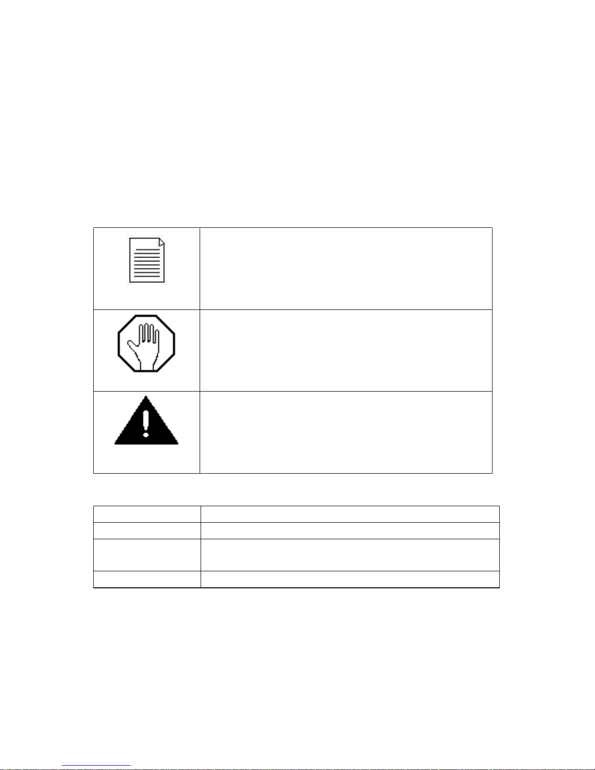
An operating procedure, condition, etc.,
which is essential to highlight.
An operating procedure, practice, etc. which,
if Not strictly observed, could result in
damage to or destruction of equipment.
An operating procedure, practice, etc., which,
if not correctly followed, could result in
personal injury or loss of life.
SHALL:
used to indicate a mandatory requirement
WILL:
used to express a declaration of purpose
SHOULD:
used to indicate a nonmandatory but preferred
method of accomplishment
MAY:
used to indicate an acceptable method
NOTE
CAUTION
WARNING
Page 5
2
2. INDOOR FLIGHT TRAINING
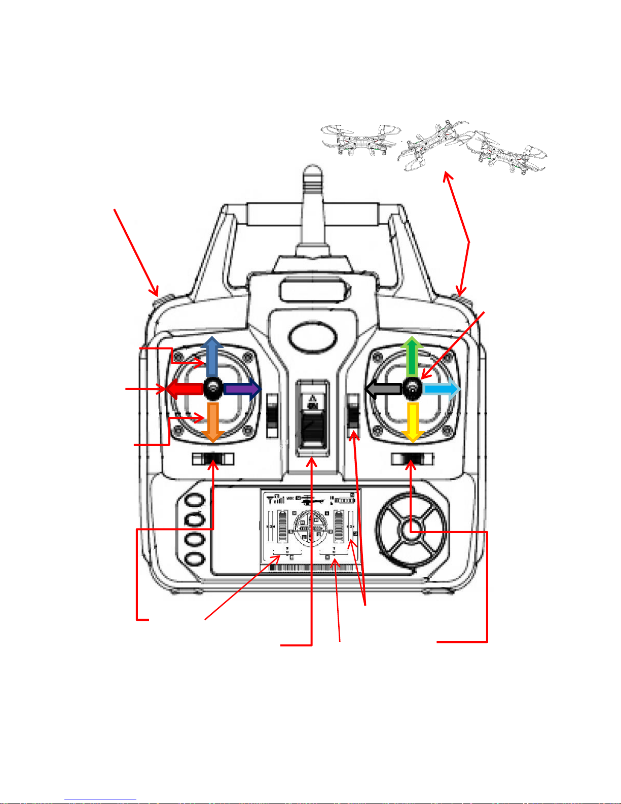
2.1 Know Your Indoor Trainer
Throttle
Cyclic
Pedals
Flip
Yaw Trim
High/Low Speed
Pitch (Fore/Aft) Trim
Roll (Lateral) Trim
Power Switch
Throttle
Page 6
3
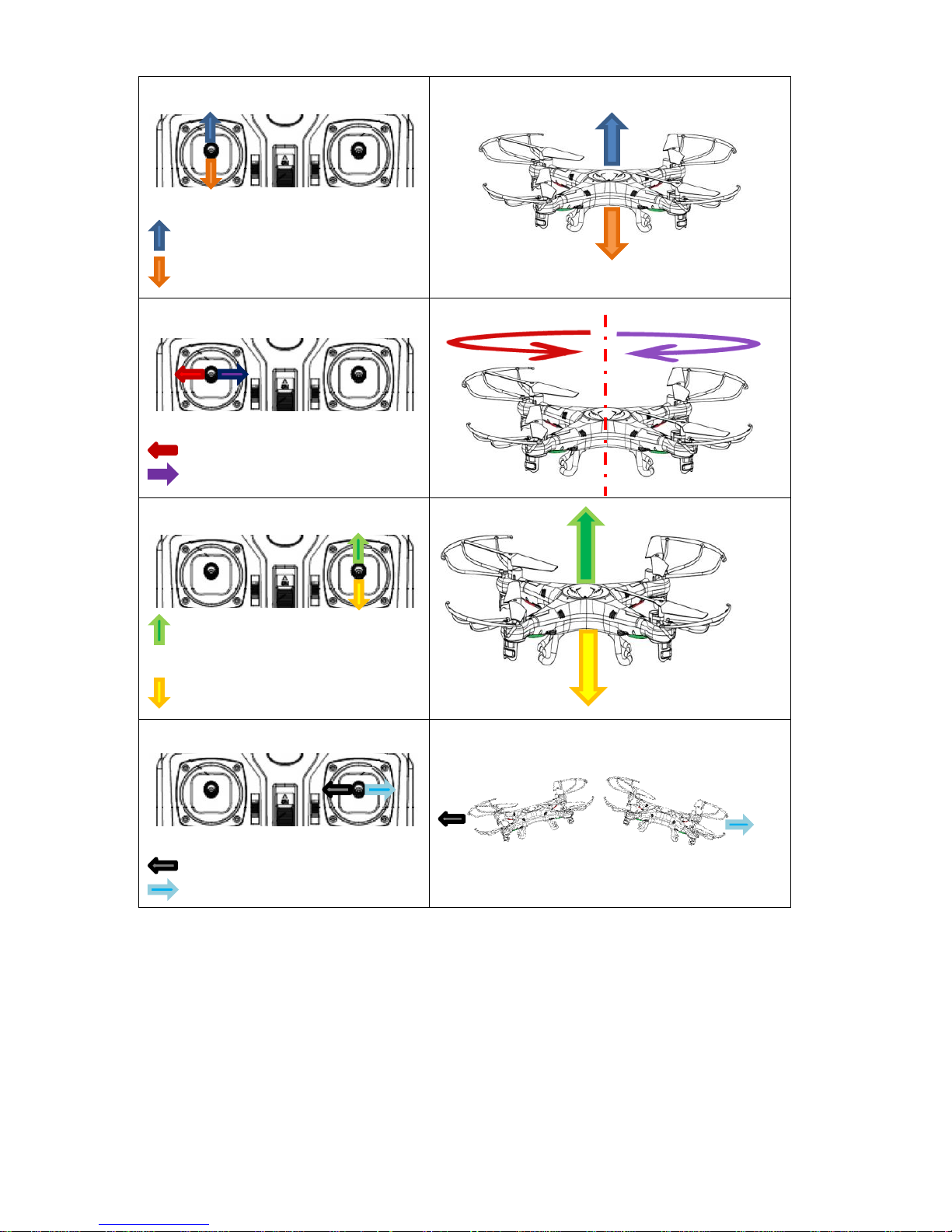
Throttle
Climb
Descend
Pedals
Yaw (rotate) Left
Yaw (rotate) Right
Fore/Aft Cyclic
Pitch (Slide) Forward
Pitch (Slide) Rearward
Lateral Cyclic
Roll (Slide) Left
Roll (Slide) Right
Page 7

4
2.2 Install, Remove, and Charge a Battery
Condition(s):
1. Battery charger plugged into wall outlet
2. Depleted Syma X5 flight battery
3. Syma X5 power switch off
4. Remote control power switch off
Standard(s):
1. Identify when battery is depleted during flight
2. Remove battery from Syma X5
3. Connect battery to battery charger
4. Identify when a battery is fully charged
5. Iinstall fully-charged battery in Syma X5
Crew Actions:
Pilot on the Controls:
1. Lower throttle to full down position when low battery
voltage is encountered
2. Turn off the Syma X5 power switch
3. Turn off the remote control power switch
Visual Observer:
1. Assist Pilot on the Controls replacing the depleted Syma
X5 battery with a fully-charged battery
Procedure:
When the quadcopter has depleted the battery, the lights on the
quadcopter blink slowly and the aircraft loses power. It is time to
replace the battery with a fully-charged battery and charge the
depleted battery. To charge a battery: connect the battery to a
single-port or five-port charger. When the depleted battery is
connected to the charger correctly, the red LED light will illuminate.
When the battery has completed charging the red LED light will
extinguish. This indicates that the battery is fully-charged and ready
to fly. The charging time is approximately 2 hours and the expected
flight time is five to eight minutes. Once the battery is fully-charged,
disconnect the battery from the charger, open the battery
compartment on the Seema X5, and connect the battery. Close the
battery compartment and continue flying.
Page 8
5
2.3 Bind Remote Control to Syma X5
Condition(s):
1. Syma X5 with battery installed and camera removed
Standard(s):
1. Properly bind the remote control to the aircraft
2. Avoid cross-binding with any adjacent aircraft
Crew Actions:
Pilot on the Controls:
1. Turn on the remote control power switch
2. Turn on the Syma X5 power switch
3. Announce “Clear on the Flight Line”
Remote Control Operator (RCO):
1. Assist Pilot on the Controls by confirming that no other
flight crew is attempting to bind a remote control to the
Syma X5 in use
Procedure:
The Pilot on the Controls will turn on the remote control first.
Then turn on the Syma X5. Place the Syma X5 right side up on a
level surface promptly. The Syma’s computer determines level
shortly after power is applied and if the pilot takes too long to
set down the Syma X5, the aircraft will not fly properly. The
lights on the quadcopter will blink slowly. Announce “Clear on
the Flight Line” and wait for any responses. When the Visual
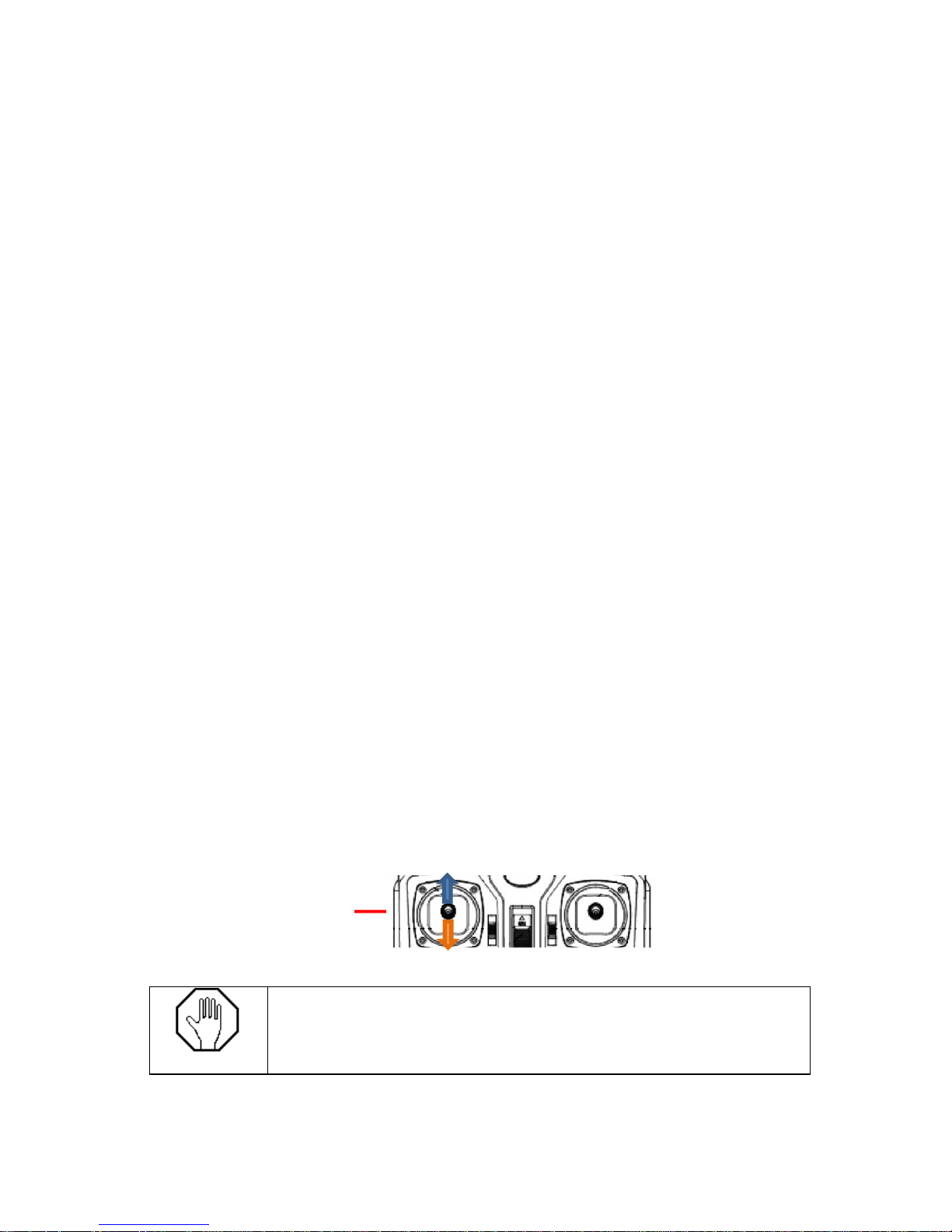
Observer confirms that the flight line is clear, apply full throttle
and then replace the throttle to the full-down position. This
binds the aircraft to the remote and the Syma X5 is ready to fly.
If two remote controls attempt to bind
simultaneously, the aircraft can become
uncontrollable.
CAUTION
To Bind: Move Throttle
Full-Up then Full-Down
Page 9

6
2.4 Flight Control Trim Adjustments
Condition(s):
1. Syma X5 with remote control bound
Standard(s):
1. Properly adjust yaw trim in order for Syma X5 to maintain
heading without control input
2. Properly adjust pitch (fore/aft) trim in order for Syma X5 to
maintain a stationary position without control input
3. Properly adjust roll (lateral) cyclic trim in order for Syma X5
to maintain a stationary position without control input
Crew Actions:
Pilot on the Controls:
1. Turn on the remote control power switch
2. Turn on the Syma X5 power switch
3. Announce “Clear on the Flight Line”
Visual Observer:
1. Assist Pilot on the Controls by confirming that no other
flight crew is attempting to bind a remote control to the
Syma X5 in use
2. Take a position perpindicular to the Pilot on the
Controls to assist in determining fore/aft drift
Procedure:
Adjust all trims (pitch, roll, and yaw) until a long tone is heard
indicating the trim is neutral. Apply throttle until the aircraft
becomes light on the landing gear. Note any tendency for the
aircraft to drift or yaw. Continue to apply throttle until the
aircraft breaks contact with the ground. If the aircraft begins to
drift, land immediately by lowering the throttle to the full-down
position to stop the rotors. Apply trim in the opposite direction
of drift. Apply throttle until the aircraft becomes light on the
landing gear. If all trims have been adjusted properly the aircraft
will not exhibit any tendency to drift. Continue to apply throttle
until the aircraft leaves the ground. The aircraft should ascend
vertically with minimal drift and no yaw. If any drift is present,
repeat this procedure.
Page 10
7
2.5 Vertical Takeoff to a 1m Hover
Condition(s):
1. Syma X5 with remote control bound
Standard(s):
1. Perform a smooth, continuous ascent to a hover
2. Establish a hover altitude of 1 meters ± ½ meter
3. Maintain heading ± 10 degrees.
Crew Actions:
Pilot on the Controls:
1. Turn on the remote control power switch
2. Turn on the Syma X5 power switch
3. Announce “Clear on the Flight Line”
4. Announce “Coming Up” just prior to takeoff
Visual Observer:
1. Assist Pilot on the Controls by confirming that no other
flight crew is attempting to bind a remote control to a
Syma X5
Procedure:
The Pilot on the Controls shall announce “Clear on the Flight
Line” and announce “Coming Up” immediately prior to applying
throttle. The Pilot on the Controls will apply sufficient throttle
to achieve a positive climb through ground effect. The Pilot on
the Controls will stabilize the aircraft at a 1m hover. Avoid the
tendency to over-control the throttle. It is possible to maintain
aircraft altitude in a hover without adjusting the throttle.
If the aircraft becomes out of control immediately
lower the throttle to the full down position to
prevent burning out the small electric motors.
CAUTION
Page 11

8
2.6 Vertical Descent and Landing from a 1m
Hover
Condition(s):
1. Syma X5 with remote control bound
2. Aircraft in a stable hover located over the intended landing
area
Standard(s):
1. Smooth, continuous descent from a hover to the ground
2. Maintain heading ± 10 degrees
3. Maintain throttle at full-down position until rotors come to
a complete stop
Crew Actions:
Pilot on the Controls:
1. Announce “Landing to the Ground”
Visual Observer:
1. Confirm to the Pilot on the Controls that the aircraft is
above the intended landing area
Procedure:
The Pilot on the Controls will apply downward pressure on the
throttle in order to achieve a 1 m/s rate-of-descent. As the
aircraft passes through 0.25 meters, the Pilot on the Controls
will VERY slowly and progressively reduce the throttle to the full
down position so that the throttle arrives at the full-down
position just after the aircraft arrives at the ground. The Pilot on
the Controls will maintain the throttle full-down position until
the rotors completely stop.
Page 12
9
2.7 Yaw Turns
Condition(s):
1. Syma X5 with remote control bound
Standard(s):
1. Perform a smooth, continuous ascent to a hover
2. Establish and maintain hover altitude of 1m ± ½ m
3. Stop at desired heading ± 10 degrees
Crew Actions:
Pilot on the Controls:
1. Announce direction of Yaw Turn Prior to turning (e.g.
“Aircraft Nose Right” or “Aircraft Nose Left”)
Visual Observer:
1. Assist Pilot on the Controls by confirming that no other
flight crew is attempting to bind a remote control to a
Syma X5
Procedure:
The Pilot on the Controls will apply pressure on the pedals in
the direction of desired yaw. The Pilot on the Controls will
return the pedals to the spring-loaded neutral position by
relaxing pressure on the pedals just prior to reaching desired
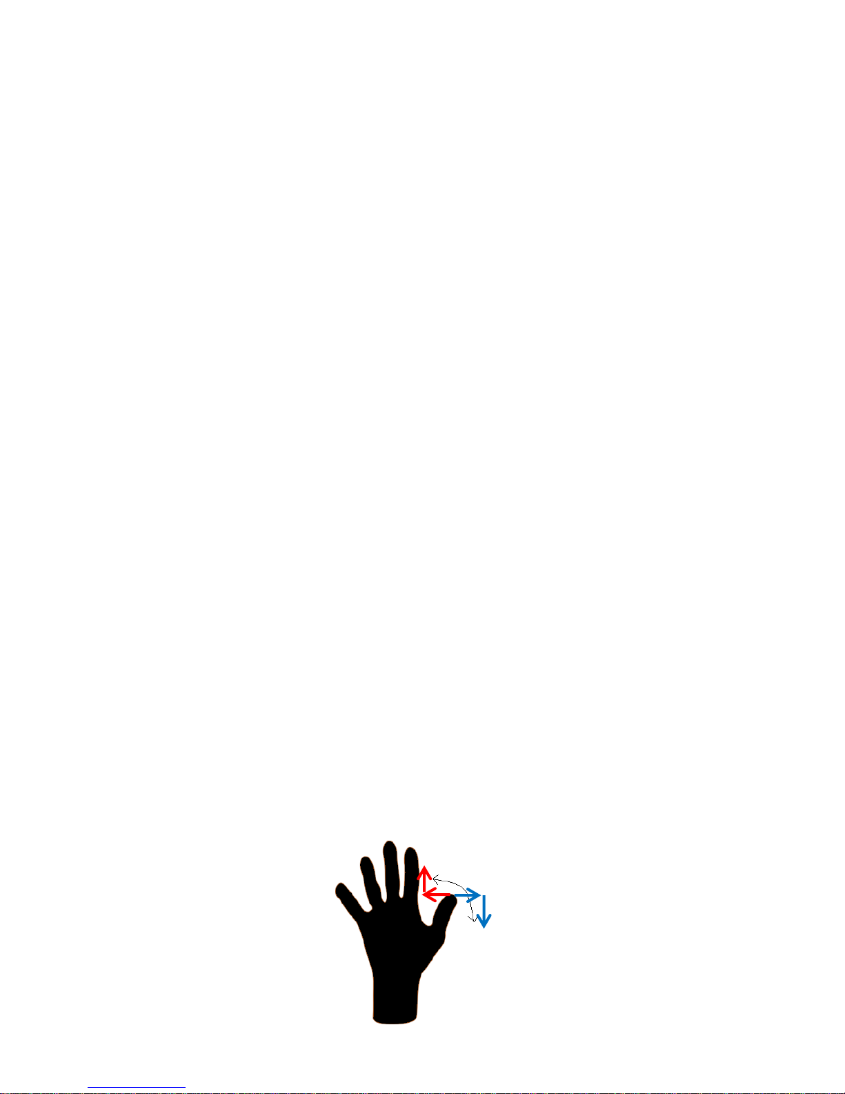
heading. Remember that the thumb travels along an arc
because it is attached to the hand. When the Pilot on the
Controls moves the thumb to the left the thumbs natural
tendency is to increase throttle and the aircraft will climb. The
opposite is true, if the thumb moves to the right, the thumb will
tend to travel down and the aircraft will descend. The Pilot on
the Controls must consciously and actively overcome the
tendency to climb in a left turn and descend in a right turn.
Page 13
10
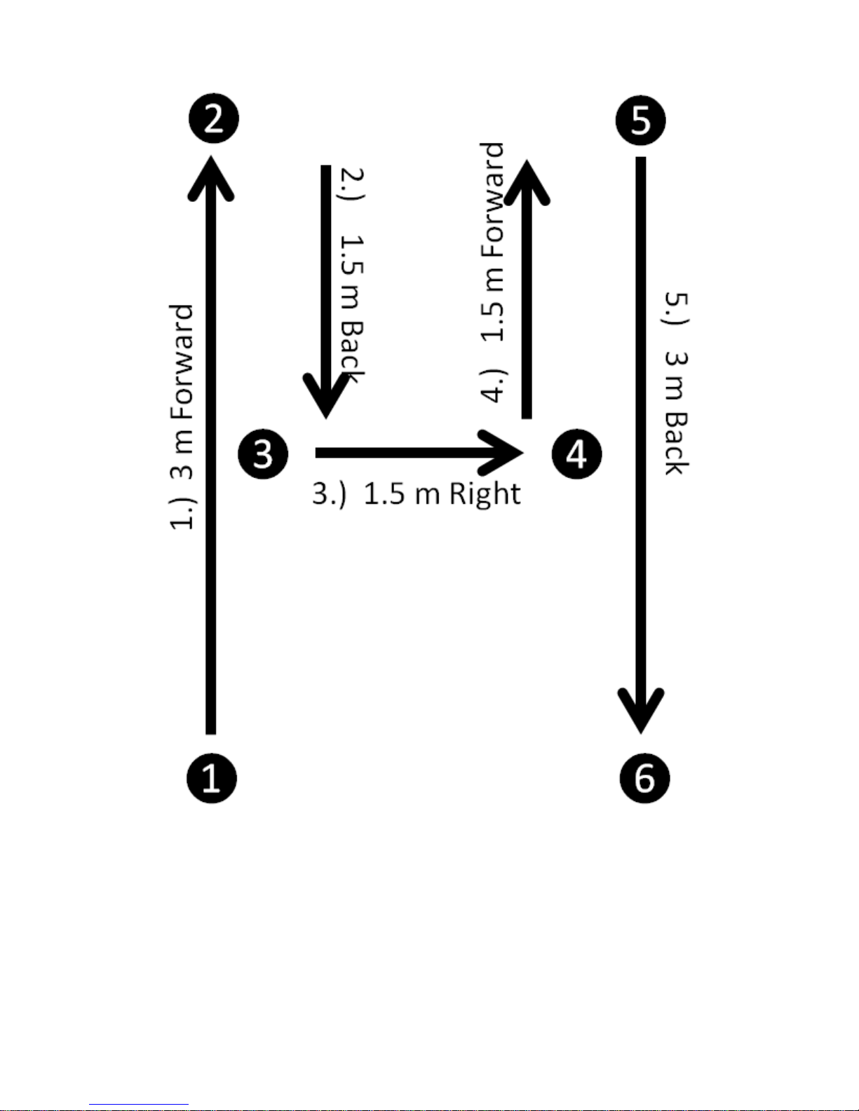
Figure 1 Indoor H Pattern
Page 14

11
2.8 Tail-In H Pattern
Condition(s):
1. SYMA X5 at 1m flight altitude
2. Sufficient clearance to perform maneuver
Standard(s):
1. Maintain consistent speed throughout the maneuver
2. Maintain desired Ground Track ± 1 meters
Crew Actions:
Pilot on the Controls:
1. Announce to the Visual Observer direction of flight
relative to the aircraft orientation. e.g. “Aircraft
Forward”, “Aircraft Aft”, “Aircraft Slide Left”, Aircraft
Slide Right”
Visual Observer:
1. Assist the Pilot on the Controls in obstacle avoidance
Procedure:
Beginning at position ❶, The Pilot on the Controls will apply forward
pressure on the cyclic to achieve 1 - 2 m/s forward flight. Smoothly
return the cyclic to the spring-loaded neutral position by relaxing
pressure on the cyclic in order to stop at position ❷. Apply aft pressure
on the cyclic to achieve 1 - 2 m/s rearward flight. Smoothly return the
cyclic to the spring-loaded neutral position to stop at position ❸. Apply
pressure to the right on the cyclic to achieve 1 - 2 m/s sideward flight to
the right. Smoothly return the cyclic to the spring-loaded neutral
position to stop at position❹. Apply forward pressure on the cyclic to
achieve 1 - 2 m/s forward flight. Smoothly stop at position ❺. Apply aft
pressure on the cyclic to achieve 1 - 2 m/s rearward flight. Smoothly
return the cyclic to the spring-loaded neutral position to terminate at
position ❻.
Page 15

12
2.9 Nose-In H Pattern
Condition(s):
1. SYMA X5 at 1m flight altitude
2. Sufficient clearance to perform maneuver
Standard(s):
1. Maintain consistent speed throughout the maneuver
2. Maintain desired ground track ± 1 meters
Crew Actions:
Pilot on the Controls:
1. Announce to the Visual Observer direction of flight
relative to the aircraft orientation. e.g. “Aircraft
Forward”, “Aircraft Aft”, “Aircraft Slide Left”
Visual Observer:
1. Assist the Pilot on the Controls in obstacle avoidance
Procedure:
The Pilot on the Controls will yaw the aircraft 180 degrees in
either direction to orient the aircraft nose-in. Beginning at
position ❶, apply aft pressure on the cyclic to achieve 1 - 2 m/s
rearward flight. Smoothly return the cyclic to the spring-loaded
neutral position to stop at position ❷. Apply forward pressure
on the cyclic to achieve 1 - 2 m/s forward flight. Smoothly
return the cyclic to the spring-loaded neutral position to stop at
position❸. Apply pressure to the left on the cyclic to achieve 1
- 2 m/s sideward flight to the aircrafts left. Smoothly return the
cyclic to the spring-loaded neutral position to stop at
position❹. Apply aft pressure on the cyclic to achieve 1 - 2 m/s
rearward flight. Smoothly stop at position ❺. Apply forward
pressure on the cyclic to achieve 1 - 2 m/s forward flight.
Smoothly return the cyclic to the spring-loaded neutral position
to terminate at position ❻.
Page 16
13
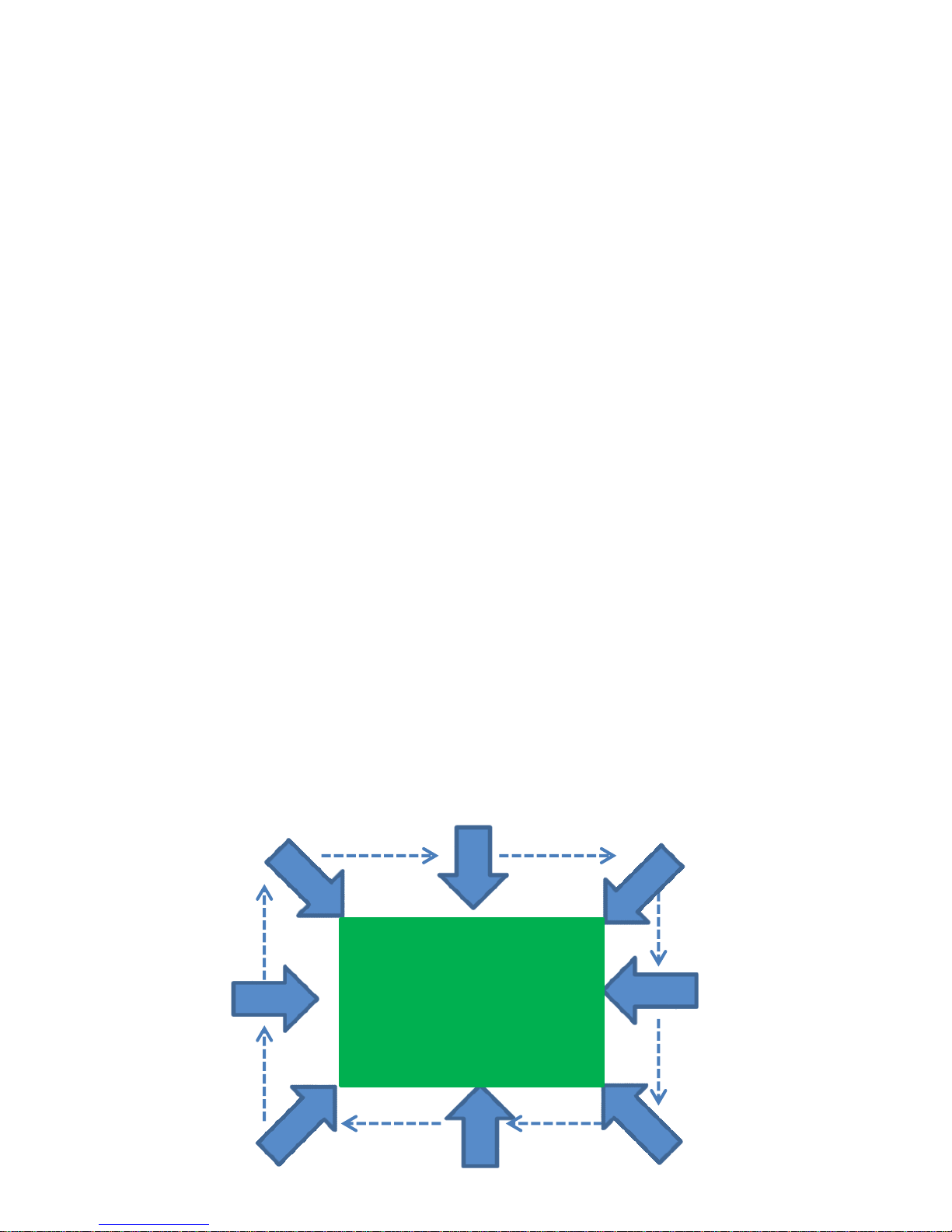
2.10 Nose-in-the-Box
Condition(s):
1. SYMA X5 at 1.5m flight altitude
2. Sufficient lateral clearance to perform maneuver
3. Nose of the aircraft oriented toward a central area
Standard(s):
1. Maintain heading ± 10 degrees of desired heading
2. Maintain desired ground track ± 1m
3. Maintain consistent speed throughout entire maneuver
Crew Actions:
Pilot on the Controls:
1. Maintain visual line of sight with aircraft throughout
entire maneuver
Visual Observer:
1. Assist the Pilot on the Controls in determining the
position of the aircraft over the intended ground track
Procedure:
Apply lateral cyclic pressure in the desired direction. Just prior
to reaching the intersecting perpendicular flight path, slowly
relax pressure on the cyclic and simultaneously apply pressure
on the pedals in the OPPOSITE direction as the cyclic. Maintain
pressure on the pedals until the aircraft has yawed 90 degrees.
Resume lateral cyclic pressure. Continue to repeat OPPOSITE
direction inputs as required.
❶
❷
❸
❹
Central Area of Interest
Page 17
14
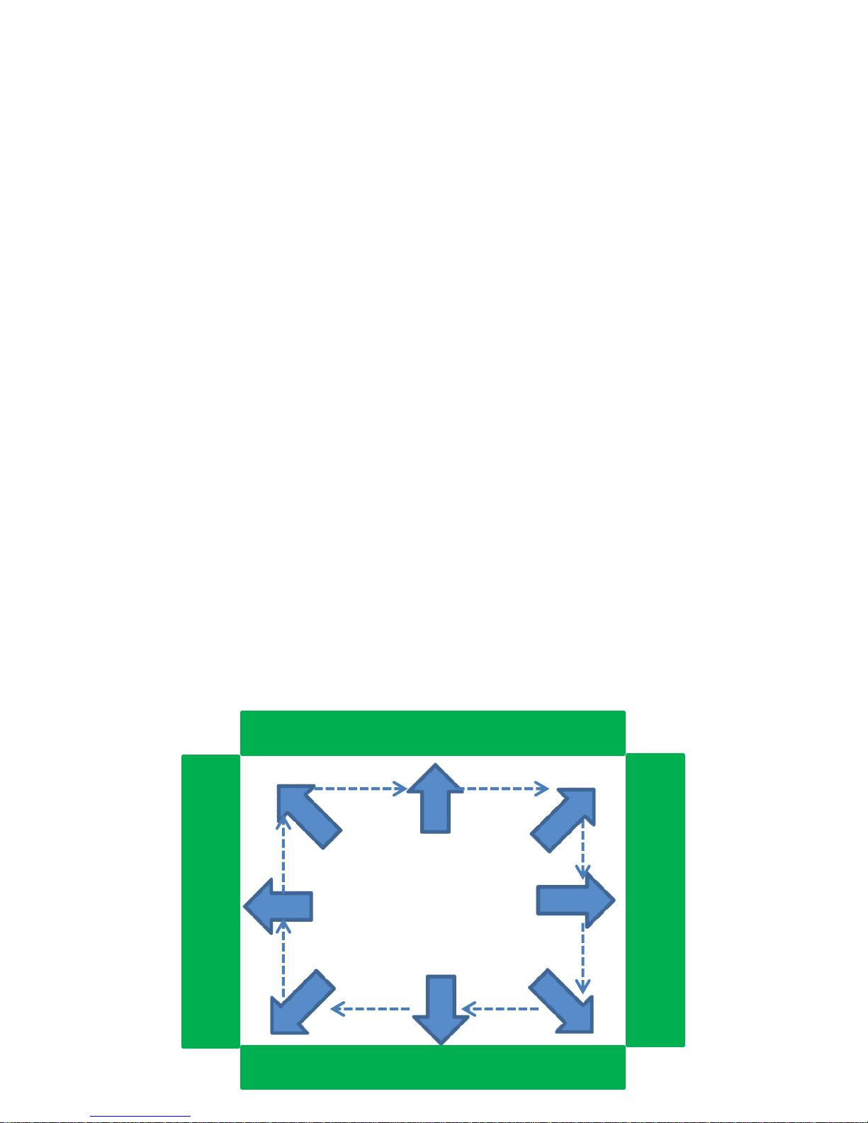
2.11 Tail-in-the-Box
Condition(s):
1. SYMA X5 at 1.5m flight altitude
2. Sufficient clearance to perform maneuver
3. Tail of the aircraft oriented toward a central area
Standard(s):
1. Maintain heading ± 10 degrees of desired heading.
2. Maintain desired ground track ± 1m
3. Maintain consistent speed throughout entire maneuver
Crew Actions:
Pilot on the Controls:
1. Maintain visual line of sight with aircraft throughout
entire maneuver
Visual Observer:
1. Assist the Pilot on the Controls in determining the
position of the aircraft over the intended ground track
Procedure:
Begin at position ❶ with the aircraft nose-in. Apply lateral cyclic
pressure in the desired direction. Just prior to intersecting the
perpendicular flight path❷, apply pressure on the pedals in the
SAME direction as the cyclic until the aircraft has yawed 90 degrees.
Begin a yaw turn by applying pressure on the pedals in the SAME
direction as the cyclic. Apply slight aft cyclic to stop forward drift.
Continue to repeat SAME direction inputs as required.
❶
❷
❸
❹
Linear Feature of Interest
Linear Feature of Interest
Linear Feature of Interest
Linear Feature of Interest
Page 18

15
2.12 Glide Slopes Approach and Landing
Condition(s):
1. SYMA X5 in flight
2. Sufficient clearance to perform maneuver
Standard(s):
1. Maintain heading ± 10 degrees of desired heading.
2. Maintain desired ground track ± 1m
3. Maintain consistent speed throughout entire maneuver
4. Maintain a constant approach angle clear of obstacles to
desired point of termination (hover) or touchdown
(surface).
Crew Actions:
Pilot on the Controls:
1. Maintain visual line of sight with aircraft throughout
entire maneuver
Visual Observer:
1. Assist the Pilot on the Controls in determining the
position of the aircraft over the intended ground track
2. Assist the Pilot on the Controls in determining obstacle
clearance while flying the approach
Procedure:
Begin with the aircraft has high as the indoor space will
practically allow. Fly toward the intended landing point. When
the desired approach angle is intercepted, begin the descent by
decreasing the throttle. Adjust the throttle as necessary to
maintain the intended glide slope. As the aircraft approaches
the desired point of termination begin to decrease the
horizontal speed by relaxing pressure on the cycle.
a.) To a hover. Progressively decrease the rate of descent and
rate of closure in order to achieve a hover at a 1 meter
altitude above the intended termination point.
b.) To the surface. Proceed as for an approach to a hover,
except after establishing a 1 meter hover, descend vertically
to the ground. After touchdown, smoothly lower the
throttle to the full down position.
Page 19
16
3. OUTDOOR FLIGHT TRAINING
3.1 Prepare the Aircraft for Flight
Condition(s):
1. Given a Precision RDASS with checklist.
Standard(s):
1. Install, secure, inspect, and inventory all mission
equipment.
2. Prepare the aircraft, flight tablet, ground station, and
remote controller for the assigned mission in accordance
with the checklist
Procedure:
In accordance with the checklist, prepare the Flight Tablet and
Ground Station for flight by verifying sufficient battery voltage,
installing the antenna, and connecting the cable. Place the
aircraft up-side down on a non-abrasive surface to check
security and condition of the landing gear, Gimbal, Camera, and
HDMI Ribbon Cable. Place the aircraft upright on a level nonmetallic surface to install the antenna and check the motors and
rotor blades. Verify the flight worthiness of the RDASS by
checking the security and condition of the rotor blades. If the
rotor blade(s) are damaged, replace the rotor blade(s) in
accordance with Aircraft Flight Manual. Prepare the radio
controller for flight by placing all switches in their nominal
position (down and away), verifying sufficient battery voltage,
and confirming trims are zeroed.
Training and Evaluation Requirements:
1. Training. Training will be conducted using the aircraft
2. Evaluation. Evaluation will be conducted using the aircraft.
Launching aircraft from a metallic service can
give erroneous magnetometer readings which
may result in uncontrolled flight.
WARNING
Page 20

17
3.2 Configure PccLite
Condition(s):
1. Precision RDASS with pre-flight checks complete.
Standard(s):
1. Correctly configure PccLite for the assigned mission in
accordance with the checklist.
Crew Actions:
Flight Tablet Operator (FTO):
1. Open the Preflight checklist
2. Announce the settings for each check before pressing
the confirm button.
Remote Control Operator (RCO):
1. Read aloud from the laminated flight checklist and
cross-monitor the tablet operator to ensure PccLite is
configured in accordance with mission requirements.
Procedure:
The laminated checklist mirrors the Preflight checklist in PccLite
to allow crew coordination while configuring PccLite. A
thorough crew brief shall be conducted prior to setting mission
limits. All flight crewmembers shall be familiar with how the
aircraft will react during all mission profiles as well as during
contingencies e.g. lost communications between the ground
station and the aircraft.
Training and Evaluation Requirements:
1. Training. Training may be conducted using the aircraft or a
simulation.
2. Evaluation. Evaluation will be conducted using the aircraft.
Page 21

18
3.3 Launch the Aircraft using PccLite
Condition(s):
1. Precision RDASS with preflight checks and PccLite preflight
checks complete up to but not including Engine Enable.
Standard(s):
1. Initiate the count-down timer on the remote control
immediately prior to takeoff..
2. Announce the remote control mode position (auto-pilot or
steering)
3. Announce current altitude and minimum altitude before
pressing the “Launch Now” button in PccLite.
4. Switch to Manual Mode on the remote control and
terminate flight if aircraft fails to maintain constant heading
or drifts excessively during takeoff.
Crew Actions:
Flight Tablet Operator (FTO):
1. Announce to Remote Control Operator “engines are
enabled”
2. Wait for the Remote Control Operator to announce
“Ready for Launch”
3. Announce current altitude and minimum altitude
before pressing the “Launch Now” button in PccLite.
4. Announce “Launching Aircraft” prior to takeoff
Remote Control Operator (RCO):
1. Confirm that the flight line area is clear
2. Verify that the count-down timer is running
3. Announce the remote control mode position (auto-pilot
or steering)
4. Announce “Ready for Launch” and carefully observe
aircraft vertical takeoff to a hover
Procedure:
The FTO will announce “engines are enabled”, press “Enable”
button. The RCO shall announce clear on the flight line, initiate
the count-down timer, and announce “Steering Mode” or
“Autopilot Mode” as appropriate. The RCO shall assume a flying
posture on the remote controller and announce “Ready for
Page 22

19
Launch”. The FTO will press confirm on the engine enable page
to advance to the launch page and then press “Launch Now”
button and announce “Launching Aircraft”.
The RCO will carefully observe the aircraft’s vertical climb to the
minimum altitude. If the aircraft drifts excessively on takeoff or
fails to maintain heading, the RCO shall without delay engage
Manual Mode and land the aircraft as soon as possible.
If the aircraft is launched in Steering mode, the RCO shall wait
until the aircraft has established a stable hover above the
lanuch point before sending flight commands. If the aircraft is
launched in autopilot mode, the aircraft can be sent on a flight
plan or flown using the virtual joysticks.
Note: it is recommended to set the minimum altitude a
minimum of 8 meters above the field elevation of the takeoff
point.
Training and Evaluation Requirements:
1. Training. Training may be conducted using the aircraft or a
simulation.
2. Evaluation. Evaluation will be conducted using the aircraft.
Page 23

20
3.4 Yaw Turns
Condition(s):
1. Precision RDASS in a stable out-of-ground-effect hover
Standard(s):
1. Maintain consistant rate-of-turn not to exceed 90 degrees
in 3 seconds.
2. Stop yaw turn ± 10 degrees of desired heading.
3. Perform three-way positive transfer of the controls
4. Announce when focus is directed to the flight tablet
Crew Actions:
Operator Controlling the Aircraft:
1. Announce direction of Yaw Turn (e.g. “Aircraft Nose
Right” or “Aircraft Nose Left”)
2. Command Left or Right yaw as appropriate
Procedure:
Yaw turns can be accomplished by using the virtual joysticks on
the Flight Tablet or with the remote control in steering mode. It
is helpful when sending flight commands with the flight tablet
to use an anchor point. Keep at least one digit fixed in place on
the side or bottom of the tablet to have a frame of reference
when displacing the virtual joysticks.
To yaws using the remote control place the Mode Switch into
Steering mode. Apply pressure on the pedals in the direction of
desired yaw. Return the pedals to the spring-loaded neutral
position by relaxing pressure on the pedals just prior to reaching
desired heading.
When the aircraft is close-in the landing gear is a useful aid for
determining orientation. For operations with greater distance
from the FTO/RCO, the flight tablet’s Line-of-Sight indicator is
better for determining aircraft orientation.
Page 24

21
3.5 Vertical Descent and Landing from a Hover
Condition(s):
1. Precision RDASS in Stable 5m Hover
2. Aircraft in a stable hover located over the intended landing
area
Standard(s):
1. Smooth, continuous descent from a hover to the ground.
2. Maintain Heading ± 10 degrees.
Crew Actions:
Flight Tablet Operator (FTO):
1. Announce to the Remote Control Operator “Landing
Now” prior to pressing the “Land Now” button”.
Procedure:
Landing may be accomplished using either the flight tablet or
the remote control.
The FTO accomplishes a vertical descent and landing by
positioning the landing waypoint on the map at the intended
landing area and pressing “Land Now”. The flight crew shall
verify that the aircraft has a clear flight path from its current
position to the landing point. The aircraft will turn toward and
fly to the landing point. When the aircraft is above the landing
point it will accomplish an automated descent and landing.
When the aircraft is on the ground the rotors will shutoff
automatically. If the rotors continue to turn after landing, Press
“Kill” under the Engine Menu in PccLite.
In order to land and using the remote control, the RCO will
place the mode switch in steering. The aircraft will not be able
to descend below the minimum altitude until the FTO presses
“Land Now”. The RCO shall position the aircraft directly over the
intended point of landing prior to the FTO pressing “Land Now”.
The RCO will apply and maintain downward throttle until the
aircraft is on the ground and the rotors have stopped.
Page 25
22
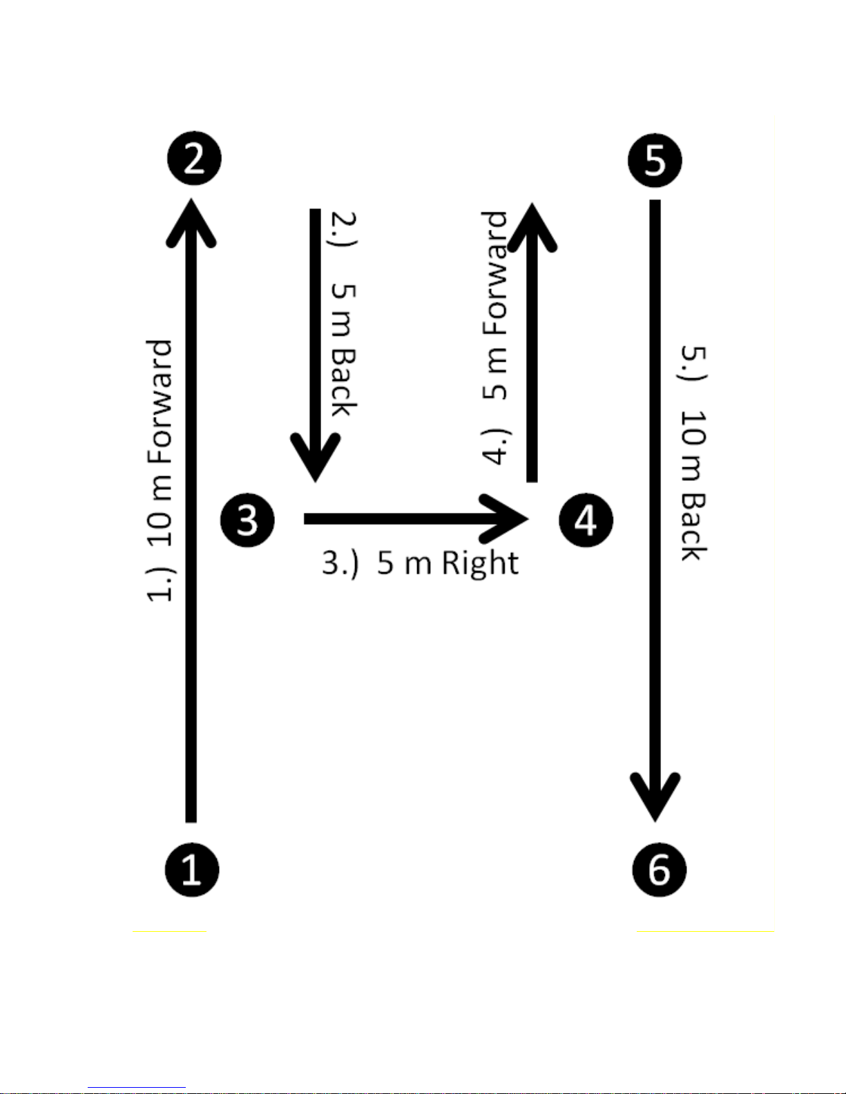
Figure 2 Outdoor H Pattern
Page 26

23
3.6 Tail-In H Pattern
Condition(s):
1. Precision RDASS at a minimum 15m flight altitude
2. Sufficient clearance to perform maneuver
Standard(s):
1. Maintain consistent speed throughout the maneuver.
2. Maintain desired ground track ± 3 meters
Crew Actions:
Operator Controlling the Aircraft (OCA):
1. Announce to the Visual Observer direction of flight
relative to the aircraft orientation. e.g. “Aircraft
Forward”, “Aircraft Aft”, “Aircraft Slide Left”, Aircraft
Slide Right”
Visual Observer (VO):
1. Assist the OCA in obstacle avoidance
Procedure:
For training the tail-in H Pattern shall be accomplished using both
the flight tablet and the remote control. Beginning at position ❶,
the OCA will apply a forward input on the cyclic to achieve 1 - 2 m/s
forward flight. Smoothly return the cyclic to the neutral position in
order to stop at Position ❷. Apply an aft input on the cyclic to
achieve 1 - 2 m/s rearward flight. Smoothly return the cyclic to the
neutral position to stop at position❸. Apply a right input on the
cyclic to achieve 1 - 2 m/s sideward flight to the right. Smoothly stop
at position❹. Apply a forward input on the cyclic to achieve 1 - 2
m/s forward flight. Smoothly stop at position ❺. Apply an aft input
on the cyclic to achieve 1 - 2 m/s rearward flight. Smoothly return
the cyclic to the spring-loaded neutral position to terminate at
position ❻.
Page 27

24
3.7 Nose-In H Pattern
Condition(s):
1. Precision RDASS at 10m minimum flight altitude
2. Sufficient clearance to perform maneuver
Standard(s):
1. Maintain consistent speed throughout the maneuver.
2. Maintain desired ground track ± 3 meters
Crew Actions:
Operator Controlling the Aircraft (OCA):
1. Announce to the Visual Observer direction of flight
relative to the aircraft orientation. e.g. “Aircraft
Forward”, “Aircraft Aft”, “Aircraft Slide Left”, Aircraft
Slide Right”
Visual Observer (VO):
1. Assist the OCA in obstacle avoidance
Procedure:
For training the nose-in H Pattern shall be accomplished using
both the flight tablet and the remote control. The OCA will yaw
the aircraft 180 degrees in either direction to orient the aircraft
nose-in. Beginning at position ❶, apply an aft input on the
cyclic to achieve 1 - 2 m/s rearward flight. Smoothly return the
cyclic to the neutral position to stop at position ❷. Apply a
forward input on the cyclic to achieve 1 - 2 m/s forward flight.
Smoothly stop at position❸. Apply pressure to the left on the
cyclic to achieve 1 - 2 m/s sideward flight to the aircraft’s left.
Smoothly stop at position❹. Apply an aft input on the cyclic to
achieve 1 - 2 m/s rearward flight. Smoothly stop at position ❺.
Apply a forward input on the cyclic to achieve 1 - 2 m/s forward
flight. Smoothly return the cyclic to the spring-loaded neutral
position to terminate at position ❻.
Page 28
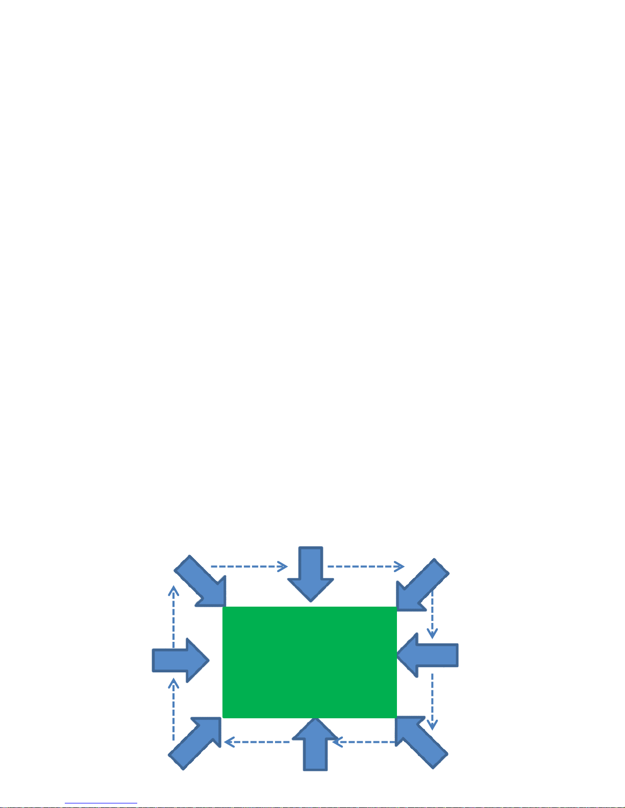
25
3.8 Nose-in-the-Box
Condition(s):
1. Precision RDASS at 10m minimum flight altitude
2. Sufficient lateral clearance to perform maneuver
3. Nose of the aircraft oriented toward a central area
Standard(s):
1. Maintain heading ± 10 degrees of desired heading.
2. Maintain desired ground track ± 3m
3. Maintain consistent speed throughout entire maneuver
Crew Actions:
Operator Controlling the Aircraft (OCA):
1. Maintain Visual Line of Sight with Aircraft throughout
entire maneuver.
Visual Observer (VO):
1. Assist the Flight Tablet Operator in determining the
position of the aircraft over the intended ground track
Procedure:
For training the nose-in-the-box shall be accomplished using
both the flight tablet and the remote control. Apply lateral cyclic
input in the desired direction. Just prior to intersecting
perpendicular flight path, slowly neutralize the cyclic and
simultaneously apply an input on the pedals in the OPPOSITE
direction as the cyclic. Maintain the pedal input until the aircraft
has yawed 90 degrees. Resume lateral cyclic input. Continue to
alternate OPPOSITE direction inputs as required.
❶
❷
❸
❹
Central Area of Interest
Page 29
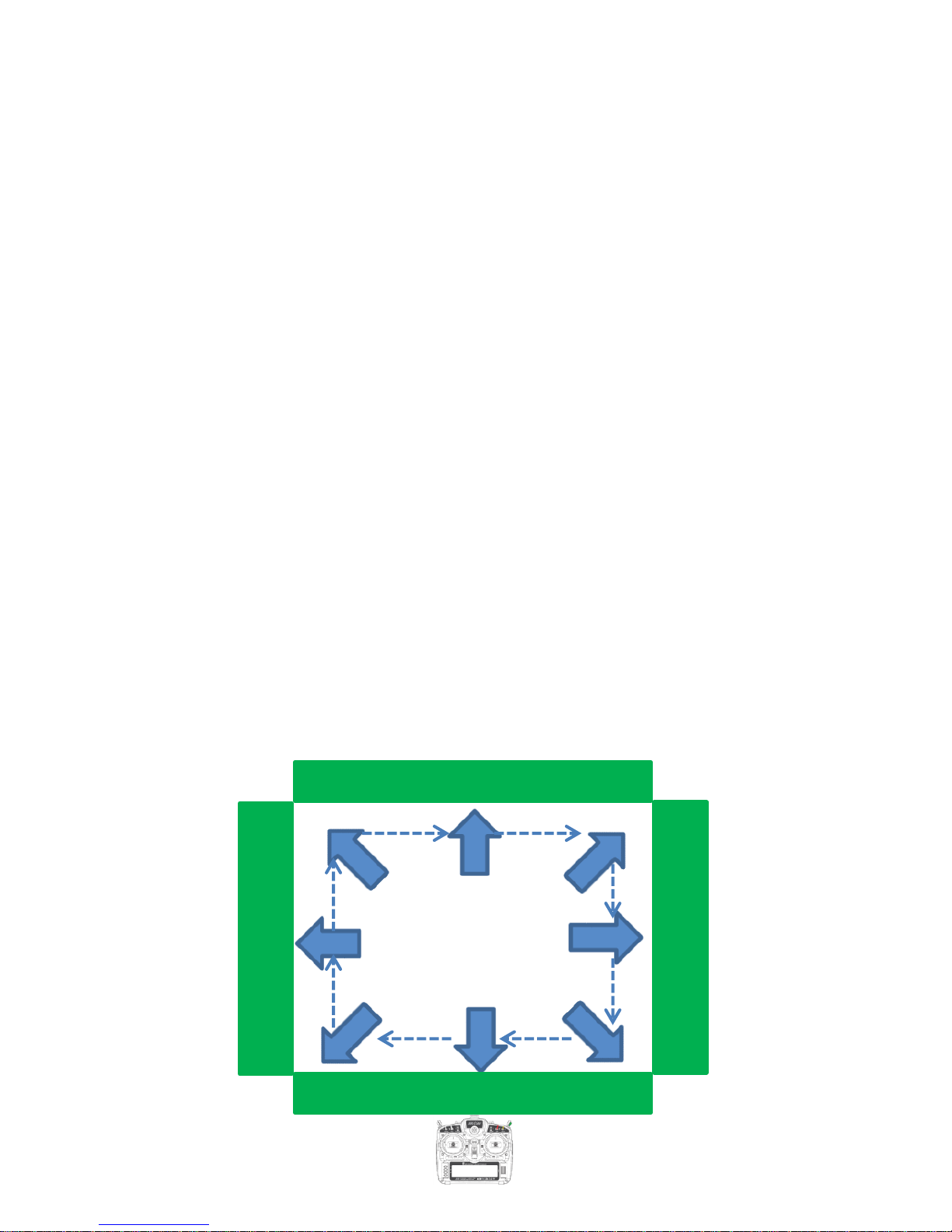
26
3.9 Tail-in-the-Box
Condition(s):
1. Precision RDASS at 10m minimum flight altitude
2. Sufficient lateral clearance to perform maneuver
3. Tail of the aircraft oriented toward a central area
Standard(s):
1. Maintain heading ± 10 degrees of desired heading.
2. Maintain desired ground track ± 3m
3. Maintain consistent speed throughout entire maneuver
Crew Actions:
Operator Controlling the Aircraft (OCA):
1. Maintain Visual Line of Sight with Aircraft throughout
entire maneuver.
Visual Observer (VO):
1. Assist the Flight Tablet Operator in determining the
position of the aircraft over the intended ground track
Procedure:
Begin at position ❶ with the aircraft nose-in. Apply lateral cyclic
input in the desired orbit direction. Just prior to intersecting the
perpendicular flight path, apply a pedals input in the SAME
direction as the cyclic input. Maintain the pedal input until the
aircraft has yawed 90 degrees. Continue to alternate SAME
direction inputs as required.
❶
❷
❸
❹
Linear Feature of Interest
Linear Feature of Interest
Page 30
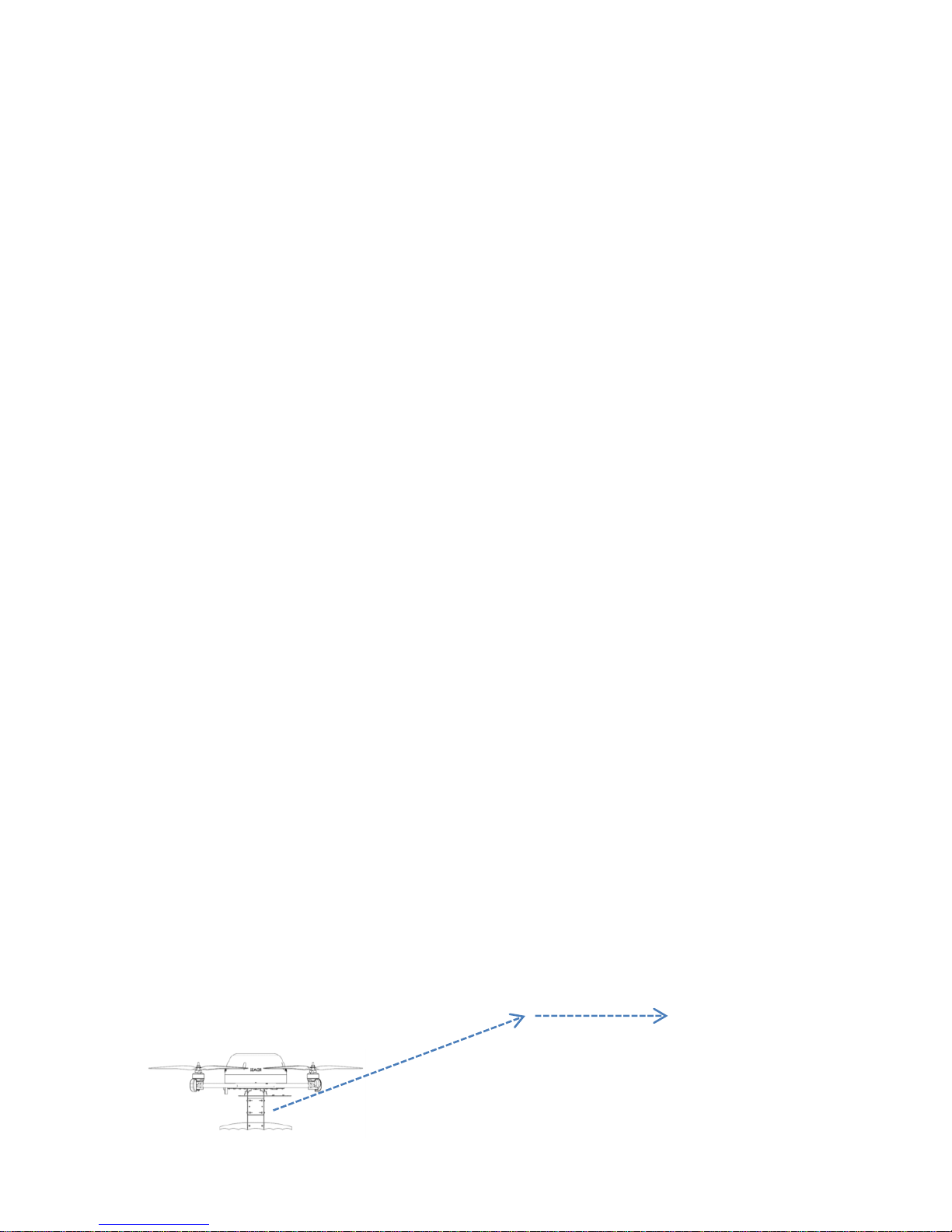
27
3.10 Climb Out
Condition(s):
1. Precision RDASS at 10m flight altitude
2. Sufficient clearance to perform maneuver
Standard(s):
1. Stop over desired point ± 5 meters
Crew Actions:
Operator Controlling the Aircraft (OCA):
1. Maintain Visual Line of Sight with Aircraft throughout
entire maneuver.
Visual Observer (VO):
1. Assist the OCA in obstacle avoidance.
Procedure:
Remote Control. Apply simultaneous forward pressure on the
throttle and the cyclic to climb up and out. As the aircraft
approaches the desired altitude relax pressure on the throttle
to allow the throttle to return to the spring-loaded neutral
position while maintaining forward pressure on the cyclic.
Flight Tablet. Increase the Fly-to altitude to desired altitude. The
aircraft will begin to climb. Apply a forward cyclic input on the
virtual joysticks in the desired direction. The aircraft will stop
climbing once it reaches the fly-to altitude.
Page 31
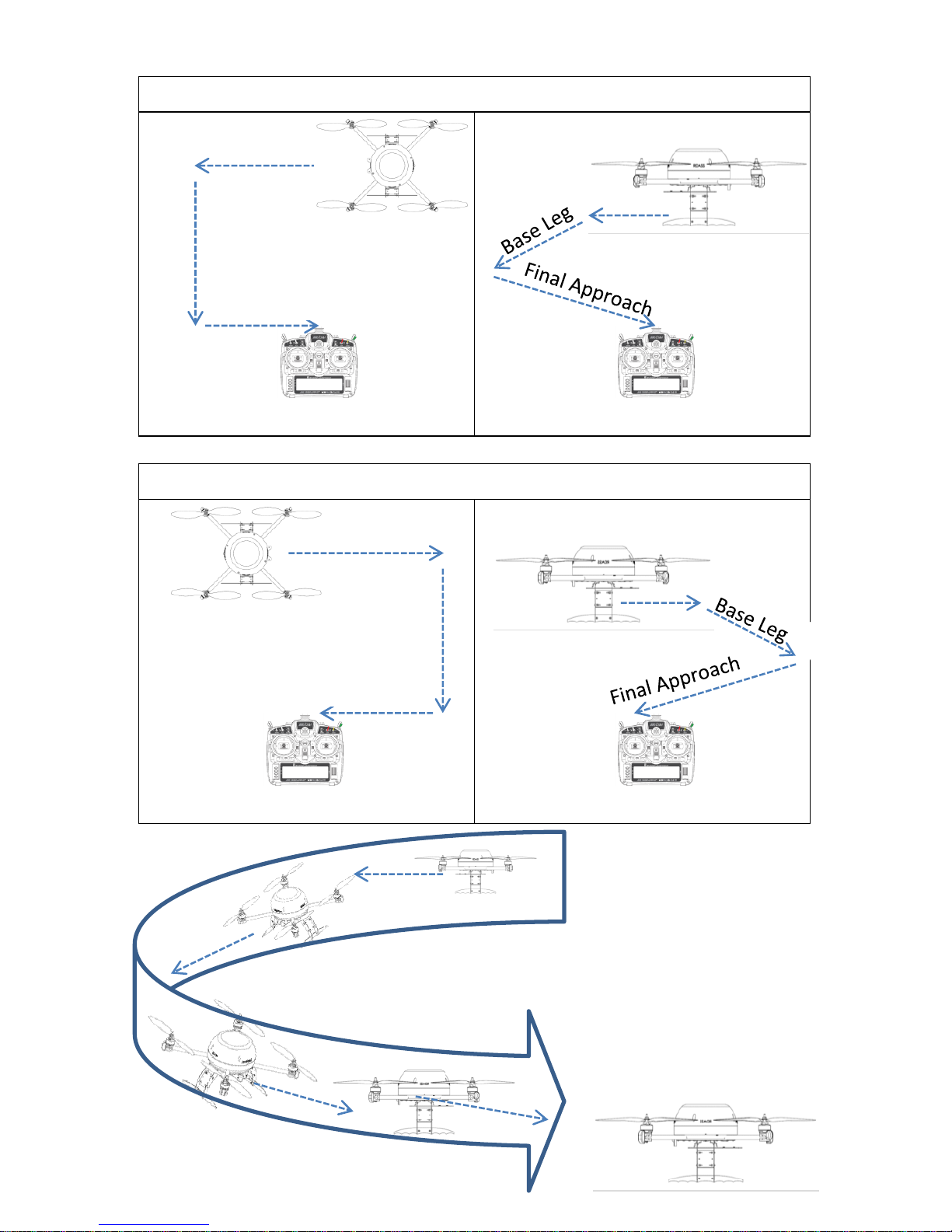
28
Left Turn Traffic Pattern
Plan View
Profile View
Right Turn Traffic Pattern
Plan View
Profile View
Downwind Leg
Downwind Leg
Downwind Leg
Downwind Leg
Base Leg
Base Leg
Final Approach
Final Approach
Page 32

29
3.11 Glide Slope Approach to a Hover
Condition(s):
1. Precision RDASS at a 35m hover altitutde
2. Precision RDASS at least 75m from the Operator Controlling
the Aircraft
3. Sufficient obstacle clearance to perform maneuver
Standard(s):
1. Maintain heading ± 10 degrees of desired heading.
2. Maintain desired ground track ± 3m
3. Maintain consistent glideslope during descent
4. Arrive within a 3m radius above intended point of landing
Crew Actions:
Operator Controlling the Aircraft (OCA):
1. Announce flight actions e.g. beginning descent, turning
left, etc.
Visual Observer (VO):
1. Operator Controlling the Aircraft in determining the
position of the aircraft over the intended landing area
2. Assist the Operator Controlling the Aircraft in
maintaining obstacle clearance and avoidance
Procedure:
Flight Tablet. Decrease the fly-to altitude to minimum altitude
or as low as obstacles allow. As the aircraft begins to descend,
use the virtual joysticks to steer the aircraft toward the point of
intended landing.
Remote Control. Simultaneously decrease the throttle and give
direction flight control inputs on the cyclic to direct the vehicle
toward the intended point of landing. If the RCO desires to
terminate the approach at the surface, the FTO must press the
“Land Now” button to allow the RCO to descend below the
minimum altitude set in mission limits.
Page 33
30
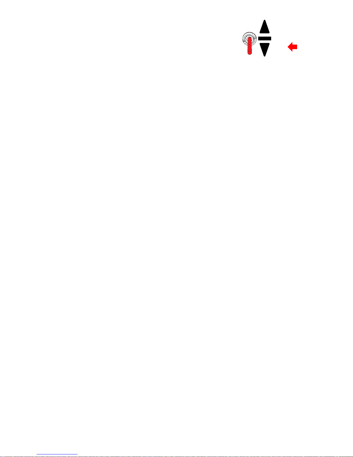
3.12 Fly in Emergency Manual Mode
Condition(s):
1. Precision RDASS at a 15m hover altitude, tail-in
Standard(s):
1. Correctly identify the Mode Switch
2. Employ crew coordination during aircraft control transfer
3. Maintain altitude ± 5m
Crew Actions:
Flight Tablet Operator (FTO):
1. Announce “Emergency, Take the Aircraft”
Remote Control Operator (RCO):
1. Engage the manual mode by placing the mode switch in
position 2.
2. Announce “I have the aircraft”
3. Maintain a tail-in aircraft orientation
Procedure:
The crew will position the aircraft at a 15m hover altitude avoiding
looking into the sun. The FTO announces “Emergency, Take the
Aircraft”. The RCO engages the Emergency Manual Mode and
announces “I have the aircraft”. The RCO adjusts the throttle as
necessary to maintain altitude. Maintain the aircraft in a tail-in
orientation. Trace an H-Pattern while maintaining altitude. If at any
time during the practice maneuver the RCO doubts the outcome or
exceeds the ± 5m standard the Remote Control shall be placed into
steering or autopilot mode without delay.
0
1 E
2
Page 34

31
Page 35

Page 36

Leptron Unmanned Aircraft Systems, Inc.
2650 East 40th Avenue Denver, Colorado 80205
(303) 384-3469 ● (800) 722-2800 ● FAX (303) 322-7242
email: [email protected] website: www.leptron.com
Printed in the United States of America
 Loading...