

Page 1
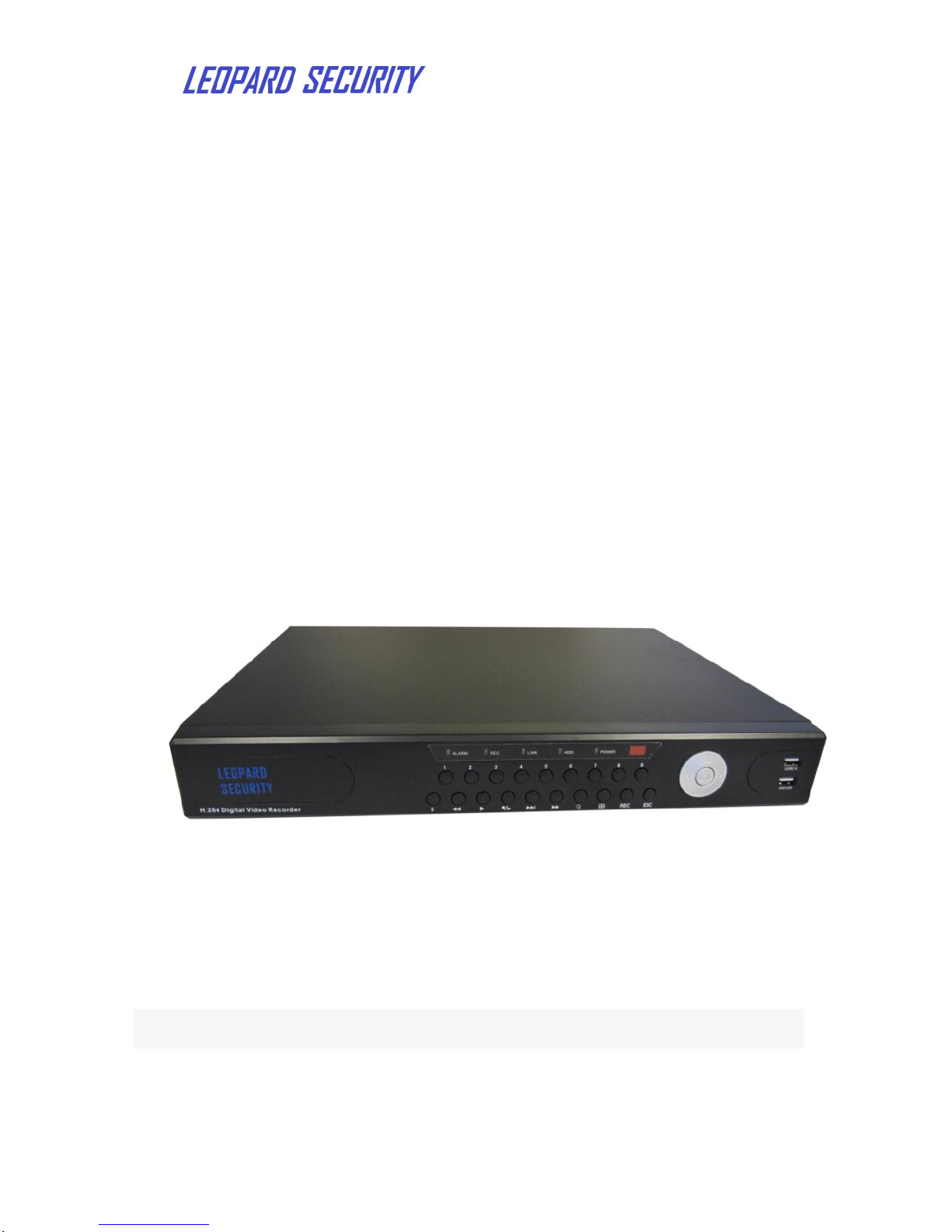
User’s Guide
1130 Cadillac Court Phone: (408) 263-0988 - 1 -
Milpitas, CA 95035 USA http://www.leopard-security.com
H.264 LI-HDSDI-DVR4
User's Guide
LI-HDSDI-DVR4 (V1.0)
Page 2

1130 Cadillac Court Phone: (408) 263-0988 - 2 -
Milpitas, CA 95035 USA http://www.leopard-security.com
Thank you for purchasing our product. Please read this user's guide carefully to
ensure that you can use the device correctly and safely.
Important Safeguards:
◆The DVR should be installed in a well-ventilated place and keep suitable space from
ground. Be sure not to block up its air vent and keep away from heat source and high
temperature environment。
◆ This equipment should be installed horizontally and avoid install at severe shaking
place(such as the trunk, above engine or rough rack).
◆To avoid fire or other damage caused by short circuit, please prevent DVR(include
external camera and accessories) from water during carwash. The machine is not
waterproof.
◆The equipment consists of precision parts. Please do not attempt to disassemble
or adjust any parts. If need maintenance, please contact the distributor or customer service.
◆Please select the hard disk which recommended by the manufacturer and suit
the DVR work requirement to meet a long time large amount of data read and write request.
Please purchase from the formal channels to ensure the hard disk quality .
◆This product can’t bear heavy weight. Please do not place heavy objects on the
product or multilayer laminated .
Disclaimer:
In the process of compiling for this user's guide, the company has been striving to make it
correct and complete. The company reserves the right to change the hardware and software
of the product without prior notice. Thank you for choosing our products and please read this
manual carefully before using. The company will not bear any economic and legal
responsibilities if any misoperation.
Page 3

User’s Guide
3
CONTENT
1. Product Introduction ..................................................................................... 4
1.1 Summary ................................................................................................. 4
1.2 Main functions………………………………………………………………… 4
1.3 Front panel buttons description ............................................................... 5
1.4 Rear panel diagram…………………………………………………………. . 6
1.5 Remote control…………………………………………………………………7
2. Basic function operation ............................................................................... 8
2.1 On/off Switching navigation ..................................................................... 8
2.2 Login…………………………………………………………………………… 8
2.3 Main menu setup guide ........................................................................... 9
2.4 Configuration management………………………………………………... 10
2.4.1 Basic configuration ......................................................................... 11
2.4.2 Live configuration .......................................................................... 12
2.4.3 Recording configuration ................................................................ 13
2.4.4 Recording schedule ...................................................................... 15
2.4.5Alarm configuration…………………………………………………..... 16
2.4.6 Network configuration.................................................................... 20
2.4.7 User management……………………………………………………...22
2.4.8 P.T.Z configuration ......................................................................... 24
2.4.9 Advanced configuration ................................................................. 27
2.5 Data retrieval ........................................................................................ 27
2.5.1 Time search ................................................................................... 27
2.5.2 Event search ................................................................................. 28
2.6 Backup ................................................................................................. 29
2.7 Check information ................................................................................ 29
2.8 Hard disk management ........................................................................ 29
2.9 Upgrade................................................................................................ 30
2.10 Logoff ................................................................................................. 30
2.11 System shut down .............................................................................. 30
Page 4

User’s Guide
4
1. Product Introduction
1.1 Summary
This device is a digital monitoring and recording product specially designed for the
security field. It adopts standalone embedded processor and Linux operating system.
The device combines with the latest technology in the IT field, such as video and
audio compression/decompression, large capacity HDD record, TCP/IP network etc.. The
code is embedded in the FLASH chip, which makes the system running more steadily. This
device has both features of digital video and audio recording(DVR) and digital video and
audio server(DVS). It can not only work locally and independently but also be compose of a
powerful security monitoring net work. With the use of professional network video
surveillance platform (network) software, it can fully reflect its strong networking and remote
monitoring capability.
It can be used for the security protection in the fields of banking, telecommunications,
electronic power, justice, traffic, residence, factory, warehouse, water conservancy facilities
and other areas and departments.
1.2 Main Functions
Real-time Monitoring
It is with analogue video output port, VGA port and HDMI port. It can realize the monitoring
function through the monitor or display. It supports simultaneous TV , VGA and HDMI
output.
Storage Function
It adopts special format to save data which cannot be tampered with and will be secured
saved.
Compression Method
It supports multi-channel audio and video signals. Each channel of audio and video signal is
compressed in real time by independent hardware. The sound and image keep stabilized
synchronization.
Backup Function
It backups through USB port(such as common U disk, mobile hard disk, SATA Combo etc.)
The client computer can download and backup the files on the hard disk via the internet
Video Playback Function
Each channel can realize independent and real-time recording, while retrieval, reverse play,
network monitoring, video search and download etc. can realize simultaneously. Multiple
playback modes: slow play, fast play, reverse play and frame-by-frame play.
When playing back the video, the exact time of the event can be displayed.
Network Operation Function
Through the internet, you can realize remote and real-time monitoring, remote video search
and playback, and remote PTZ control.
Communication Port
With RS422 port and PTZ control.
With standard Ethernet port and network remote control function.
PTZ Control
Page 5
User’s Guide
5
Support the PTZ decoder which communicates through RS422. Can expand multiple
decoding protocols, facilitating the realization of PTZ and dome camera control.
Intelligent Operation
Mouse operation function. For the same settings on the menu, you can copy and paste
quickly.
When you receive the product, please check the accessories are complete or not.
DVR accessories generally include: mouse, power lines and data lines.
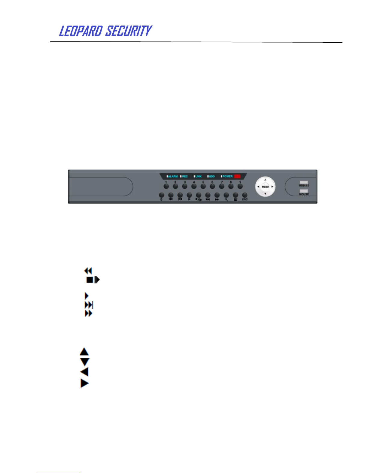
1.3 Front panel buttons description
Statement: About the front panel interface, button layout and type, to the real product
shall prevail.
The front panel buttons Description:
Buttons on Front Panel
1) STANDBY: Press to enter the system standby mode.
2) IR Sensor: IR receiver for the remote control.
3) LED Indicators: Shows status of alarm, recording, power.
4) Channel/Numbers/Playback: Press buttons 0~9 to view the selected channel in
full-screen; press buttons 0~9 to input passwords and user IDs; during playback, press the
following:
• 6/ : Increase reverse playback speed 1X, 2X, 4X
• 7/ : Press to freeze playback to one frame, then press again to advance
frame-by-frame
• 8/ : Press to start playback
• 9/ : Press to slow playback speed by 1/2, 1/4, 1/8
• 0/ : Press to increase forward playback speed 1X, 2X, 4X
5) MENU/ OK: Press to open/close the main menu or confirm.
6) Navigation: Press the Navigation buttons to perform the following:
•: In menus, press to confirm selections; in PTZ mode, press to change the navigation
buttons to control the connected PTZ camera (not included)
• : Press to move cursor up; in PTZ mode, press to pan camera up
• : Press to move cursor down; in PTZ mode, press to pan camera down
• : Press to move cursor left; in PTZ mode, press to pan camera left
• : Press to move cursor right; in PTZ mode, press to pan camera right
7) USB: Connect a USB flash drive to the top port for data backup and firmware
upgrades. Connect a USB mouse to the bottom port.
Page 6
User’s Guide
6
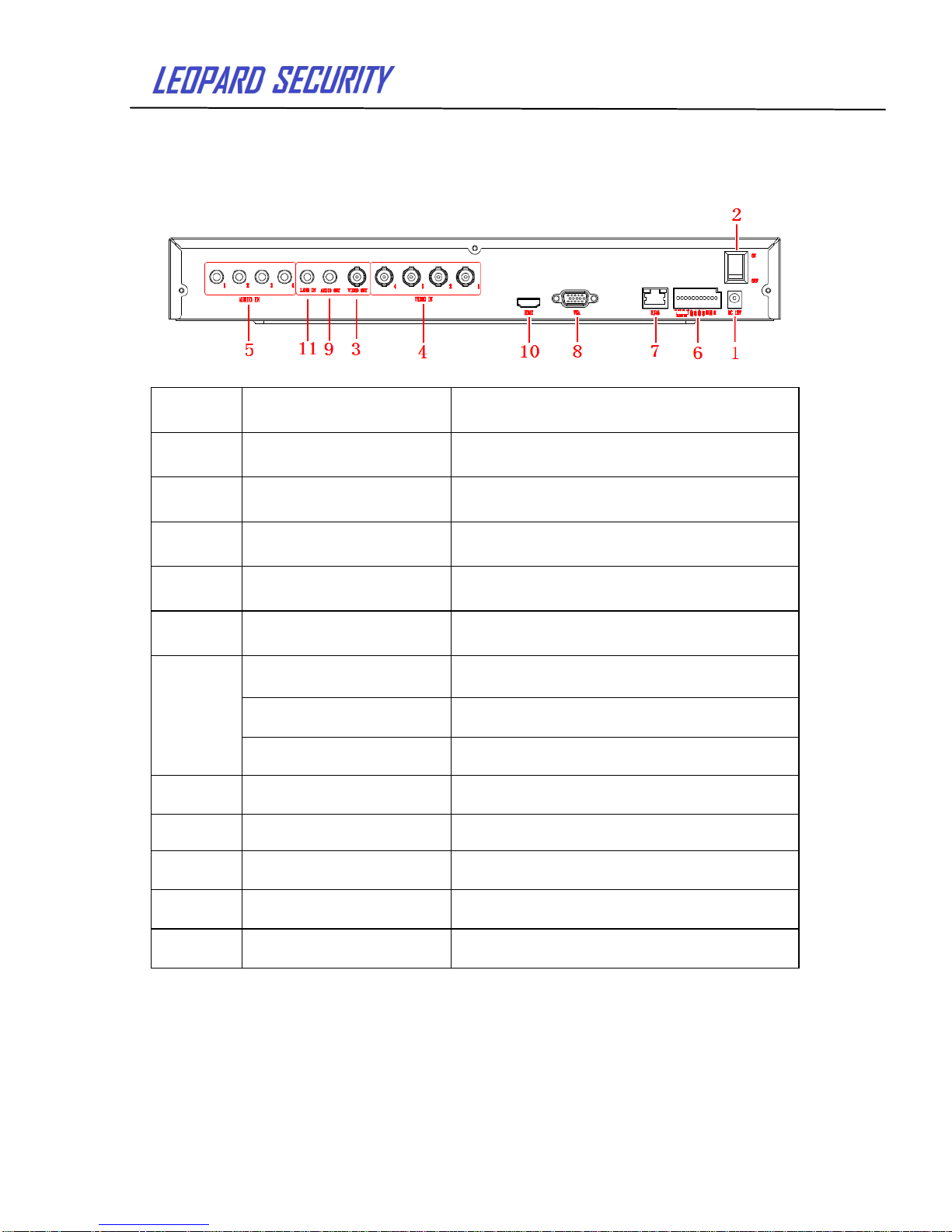
1.4 Rear panel diagram
Statement: About the rear panel interface, button layout and type, to the real product
shall prevail. The rear panel picture below may be different with the actual panel.
Connectors on Rear Panel:
Item
Physical connector
Connector description
1
Power input
DC 12V/5A
2
Power switch
POWER ON/OFF
3
Video output
Video output to connect TV or
monitor (BNC)
4
Video input
To connect analog video signal
input (BNC)
5
Audio Input
To connect audio signal input
6
Alarm Input
4 I/O alarm input
Alarm Output
I/O output for alarm
RS 422
RS 422 to connect PTZ
7
Network
To connect Ethernet
8
VGA
To connect VGA monitor
9
Audio Output
To connect audio output
10
HDMI
To connect HDMI monitor
11
LINE IN
To connect Intercom equipment
1.5 Remote control
Page 7
User’s Guide
7
TIP: When using the remote
control to enter password and
camera titles, select the field
using the navigation buttons by
press ENTER first, and then
press the number buttons.
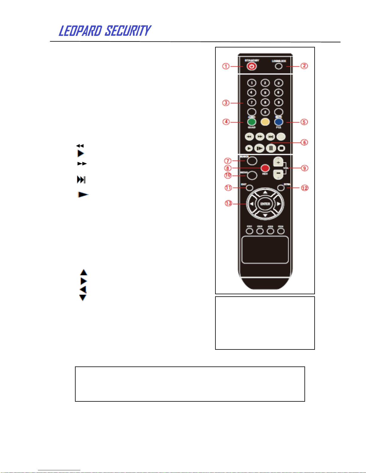
The remote control is the secondary input device
for navigating the system’s interface.
To use the remote control:
1.STANDBY:Press to turn standby mode ON/OFF.
2.LOGIN/LOCK: If "Security Option" has been
enabled in the Setup menu, press to open the user
password login screen.
3. Number/Channel buttons: In menu interface,
press buttons 0~9 to enter values; in live viewing
interface, press to view channels in full-screen.
4.QUAD: Press to switch between quad and
split-screen displays.
5. PTZ: Press to open the PTZ control window.
6. Playback controls :
• : Increase reverse playback speed 2X, 4X, 8X.
• : Press to start playback.
• : Press to increase forward playback speed
2X, 4X, 8X.
• : Press to slow playback speed by 1/2, 1/4,
1/8.
• : Press to play frame-by-frame.
• ║: Press to freeze playback on one frame.
• ■: Press to stop playback.
7. SERACH: Press to stop playback
8. RECORD: Press to start manual recording,
then press again to stop manual recording.
9. +/ - : In menu interface, press to adjust values.
10. MENU: Open the main menu.
11. EXIT: Close the menu window.
12. EXTRA: For the future use.
13. Navigation/Enter:
• : Move cursor up;
• : Move cursor right;
• : Move cursor left;
• : Move cursor down;
• Enter: In menu interface, press to confirm
selections; in playback and preview interface, press to
view system information.
For the convenience of reading and quick querying, the following
sections use the example of 4-channel DVR to introduce the details, and pictures
are base on this model. Other model’s operation interface are the same except
channel numbers and frame rate.
Page 8
User’s Guide
8
2. Basic function operation
2.1 On/off Switching navigation
2.1.1 Start
Before start,please ensure that all parts connected well!
Power on
Equipment starts and POWER indicator light is red.
2.1.2 Power off
User can power off the device by using remote controller、keyboard and mouse.
2.1.3 By remote controller:
Press Power button and the Shut down window will appear. Click OK, then the unit
will power off after a while.
2.1.4 Disconnect the power by keyboard and mouse:
Step1: enter into Menu, then select “System Shut Down” icon. The Shut down window
will appear .
Step2: click OK and the unit will power off after a while.
Step3: disconnect the current source.
2.2 Login
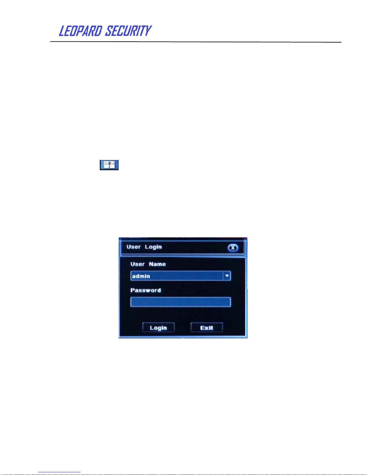
Equipment starts and the 【POWER】indicator light turns on. The initial password is
blank. After equipment starts, press 【MENU】key on panel or press right key on mouse. It
will pop up the login interface as below:
Pic 2-1 User login
After Input matching user name and password, you can enter system to setup and
operation.
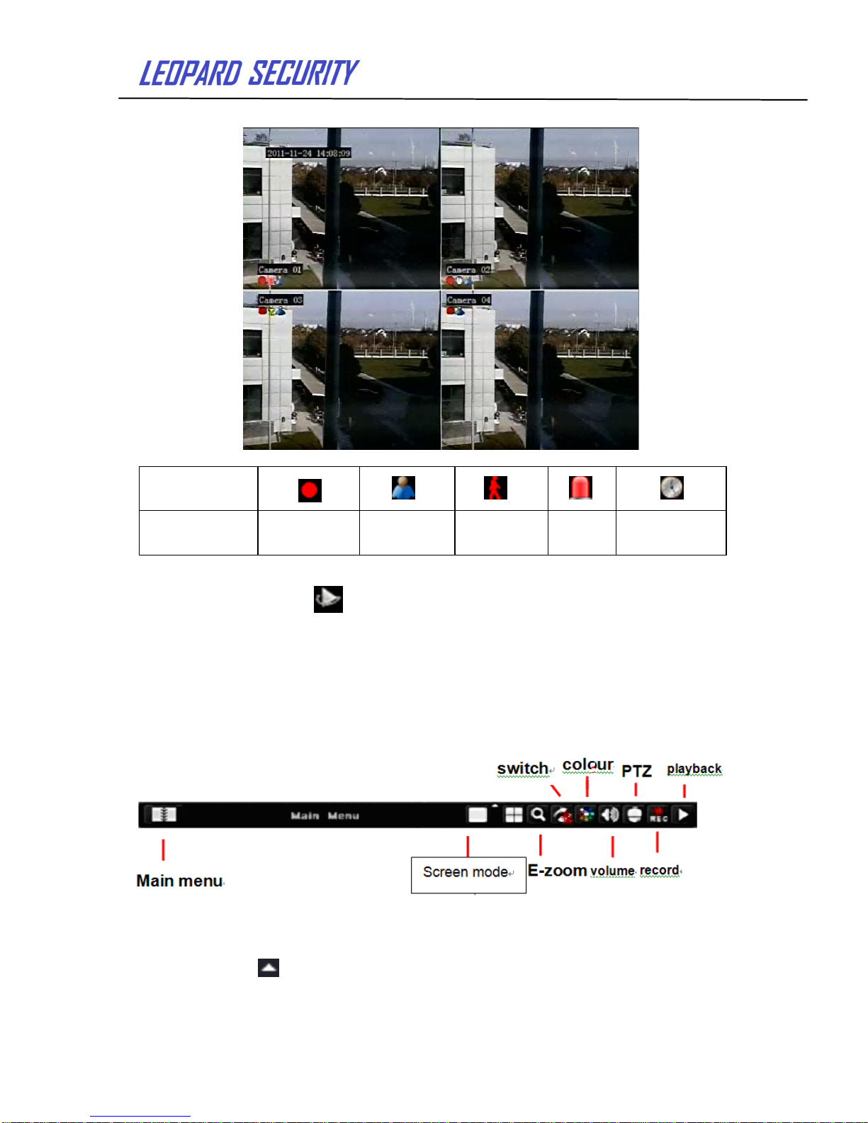
Live preview interface:
Page 9
User’s Guide
9
Live playback
Click Play button to play back the record video. As below picture: User can
operate by click the buttons on screen.
2.3 Main menu setup guide
Menu bar: Click right mouse or press ESC button on the front panel, the control bar
will display on the bottom of the screen, refer to pic2-2
Pic 2-2 Menu bar
Click the icon near Screen mode and channel choice box appears as below
Icon
Description
Recording
Manual
recording
Motion
detection
Alarm
Timing
recording
Page 10
User’s Guide
10
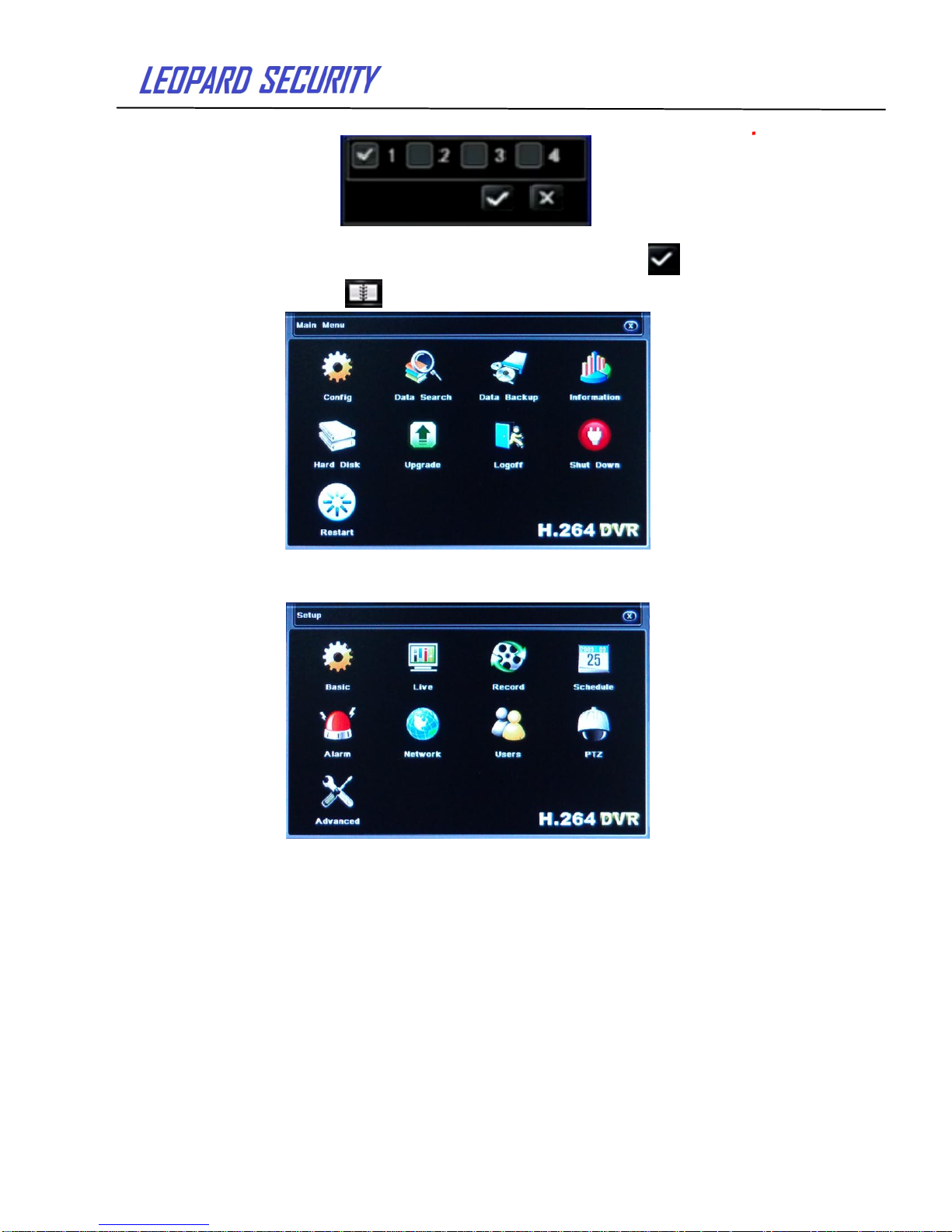
Pic 2-3 Channel choice box
User could choose 1 channels from 1-4 to show live video. Click to save.
Click function menu ,will show dialogue frame as Pic2-4:
Pic 2-4 Main Menu
Click “Config” icon and display sub-window as pic2-5:
Pic 2-5 Configuration management”
Press MENU button on the front panel or the same button on remote control,
also could display the same window.
2.4 Configuration management
Configuration Management contains nine sub-menu: Basic configuration,
Live configuration, Recording configuration, Recording schedule, Alarm configuration,
Network configuration, User management, PTZ configuration and Advanced configuration.
Page 11
User’s Guide
11
2.4.1 Basic configuration
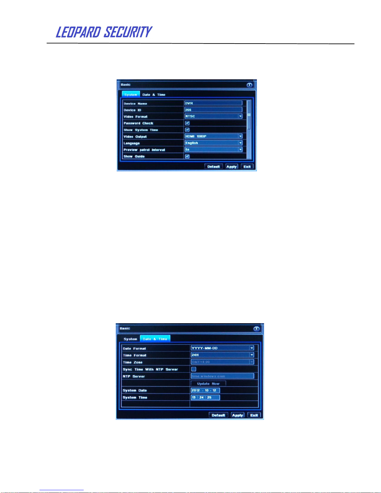
Click“Basic configuration” as pic2-6. The basic configuration contains two
sub-menu: system and date& time.
1) System
Pic 2-6 System
In this interface user can set up the device name, device ID, video format , Video
Output, language and so on. The definitions for every parameters display as below:
Device name: It may display on the client end or CMS that help user to recognize the
device remotely.
Device ID: Corresponding with the remote control number
Video format: Two modes: PAL and NTSC. User can select the video format
according to the camera.
Password check: Enable this option and user needs to input user name and
password to do corresponding operations in system configuration.
Show system time:Choose to display the system time or not
Video output: The resolution of live video and option from: VGA800*600,
VGA1024*768, VGA1280*1024 and HDMI 1080P.
Language: Set up the menu language. Simplified Chinese and English.
Click the "Default" button and the system restore the default setting ;
Click the "Apply" button to save the above setting; click the "Exit" button to exit the
current interface. If the language and video output change, the device will restart.
2 ) Time & date
Pic 2-7 Time & date
Page 12
User’s Guide
12
Set up the date format, time format and time zone. Check the" Sync Time With NTP
Server" to update from the network time server. You can also manually adjust the system
time.
Note: The system default is GMT time zone, please choose GMT +8 in the time
zone drop down list.
Click the "Default" button to restore the default settings;
Click the "Apply" button to save the above settings;
Click the "Exit" button to exit the current interface.
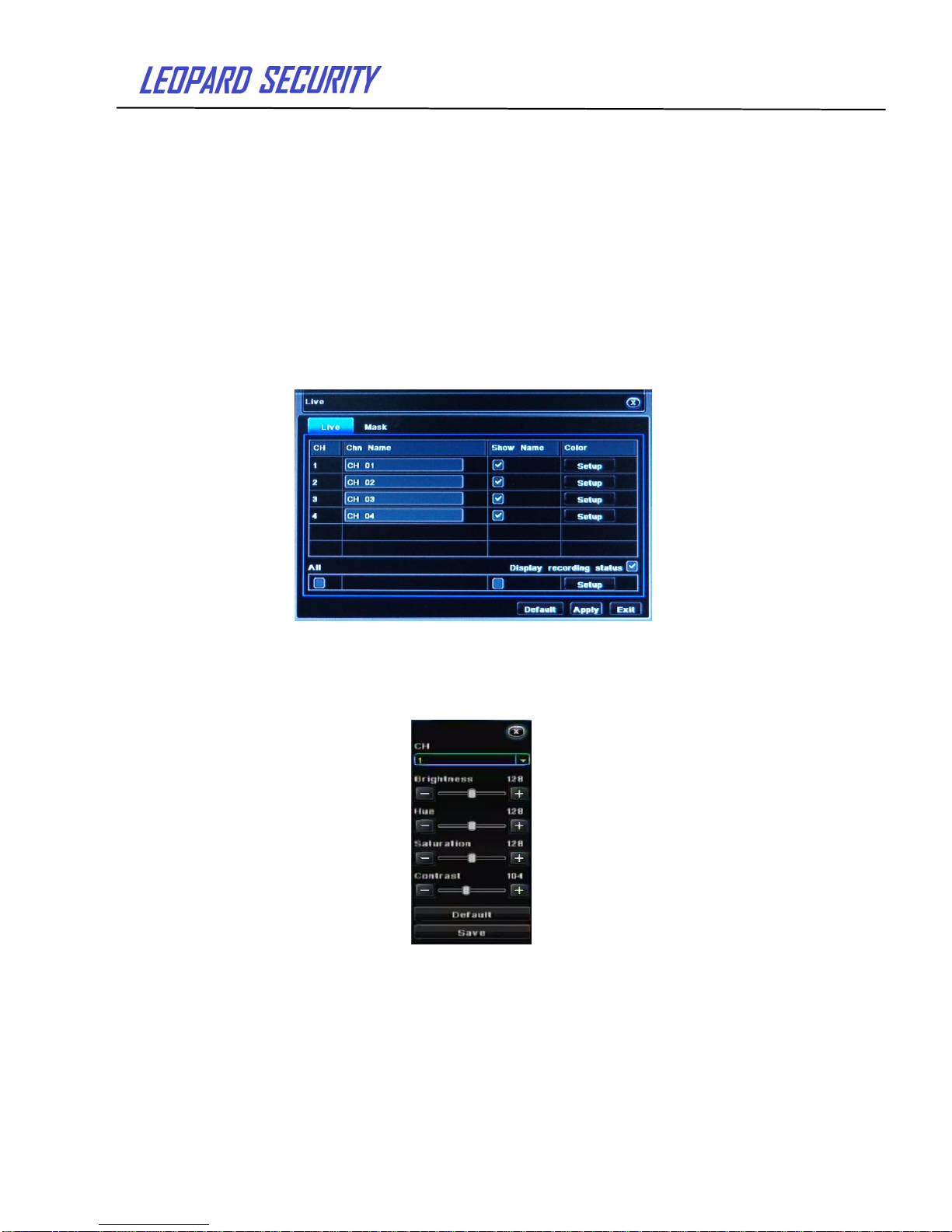
2.4.2 Live configuration
Click“Live configuration”as pic 2-8.
Live configuration includes two submenus : live and mask
2.4.2.1 Live configuration
Pic 2-8 Live configuration
Note: Click Channel Name to see a soft keyboard. User can choose
different character format to input.
Then click “Setting” button to display a window as below:
Pic 2-9 Adjustment
In this interface, user can adjust brightness, hue, saturation and contrast; click
“Default” button to resort default setting; click “Save” button to save the setting.
User can set up all channels with same parameters, please choose “all” and then do
relevant adjustment.
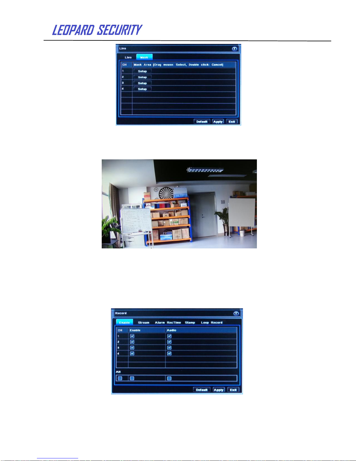
2.4.2.2 Mask
Private mask. User can set up private mask area on the live video picture.
Page 13
User’s Guide
13
Pic 2-10 Mask
Set up mask area: Click Set up button to enter into live video image to left click and
drag mouse to set mask area, refer to below picture. Click Apply button to save the setting.;
Delete mask area: Select a certain mask area. Left click to delete that mask
area and click Apply button to save the setting.
Live image mask area
2.4.3 Recording configuration
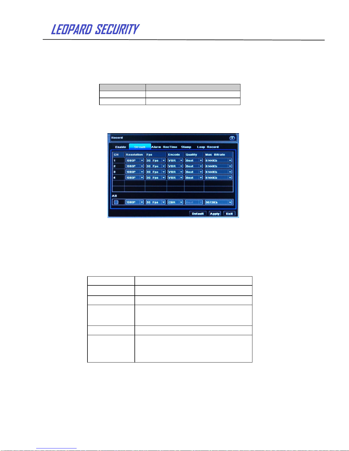
Click“Recording configuration”as pic2-11:
Recording configuration includes four submenus: Enable, Video Stream, Recording
Time, Stamp and Loop Record.
2.4.3.1 Enable
Pic 2-11 Enable
Page 14
User’s Guide
14
Check to enable channel and audio.
User can set up all channels with same setting by checking “All”.
Click “Default” button to resort default setting; click “Apply” button to save the setting;
click “Exit” button to exit current interface.
Video parameter instruction
2.4.3.2 Video Stream
Pic 2-12 Video Stream
Set up resolution, Fps, quality, encode and max bit stream.
User can set up all channels with same setting by checking “All”.
Click “Default” button to resort default setting; click “Apply” button to save the setting;
click “Exit” button to exit current interface.
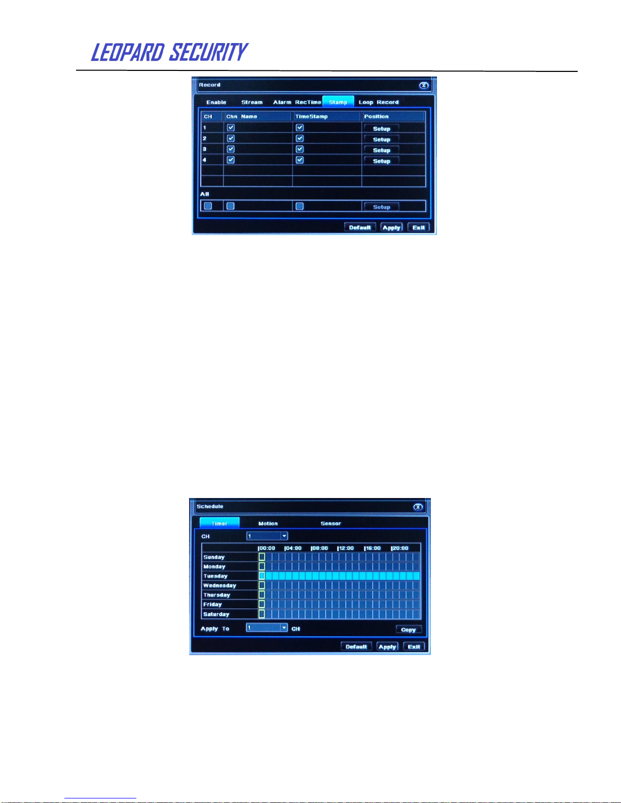
2.4.3.3 Stamp
Stamp:User can overlap the channel name and time on the video.
Parameter
Meaning
Enable
Enable the channel for recording
Audio
Enable Audio of the channel
Parameter
Meaning
Fps
Range from 1-30(NTSC)1-25(PAL)
Resolution
Support 1080P、720P
Quality
The higher the value is, the clearer the
Recorded image is. Six options:lowest,
lower, low, medium, higher and highest.
Encode
Support CBR and VBR
Max bit rate
Select range:256 Kb、512Kb、
768Kb,1024Kb,2048Kb,3072 Kb,
4096Kb,5120 Kb,6144 Kb,7268 Kb,
8192 Kb
Page 15
User’s Guide
15
Pic 2-13 Stamp
Check camera name and time stamp; click Setting button, and then user can use
cursor to drag the camera name and time stamp in random positions. User can also set up
all channels with same setting.
Click “Default” button to resort default setting; click “Apply” button to save the setting;
click “Exit” button to exit current interface
2.4.3.4 Loop Record
Check loop record to enable the loop record function. It will automatically cover the
earlier recorded files and keep recoding when HDD is full. If disabled this function, it will stop
recording when HDD is full. Note: the higher image quality, frame rate and resolution setting
need more hard disk space.
Click “Default” button to resort default setting; click “Apply” button to save the setting;
click “Exit” button to exit current interface.
2.4.4 Recording Schedule
Recording Schedule includes two submenus: timer, motion and sensor.
2.4.4.1 Timer
The vertical list means the seven days of a week from Monday to Sunday; the row
means 24 hours of a day. Click the grid to do relevant set up. Blue means selected area,
gray means non-selected area.
Pic 2-14 Timer
Copy:User can apply the timer setting of certain channel to other or all channels. Just
only select channel and click “Copy” button.
Click “Default” button to resort default setting; click “Apply” button to save the setting;
click “Exit” button to exit current interface.
Page 16
User’s Guide
16
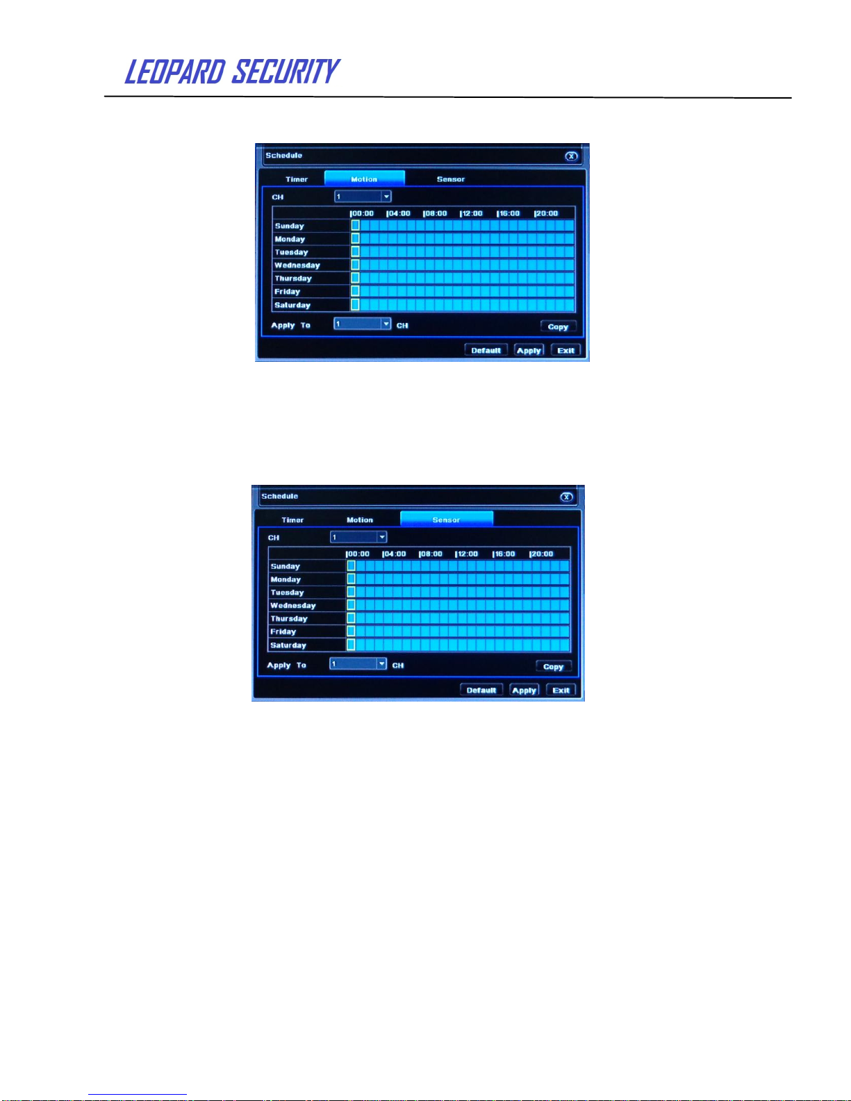
2.4.4.2 Motion
Pic 2-15 Motion
The setup steps of motion are familiar with timer.
Note: The default schedule of motion detection is full-selected.
2.4.4.3 Sensor
Pic 2-16 Sensor
The setup steps of alarm are familiar with timer.
Note: The default schedule of sensor is full-selected.
2.4.5 Alarm configuration
Alarm configuration includes five submenus: sensor alarm, motion, video loss and
alarm out.
2.4.5.1 Sensor
Sensor includes two submenus: Basic, Alarm Handling and Schedule.
1> Basic
Page 17
User’s Guide
17
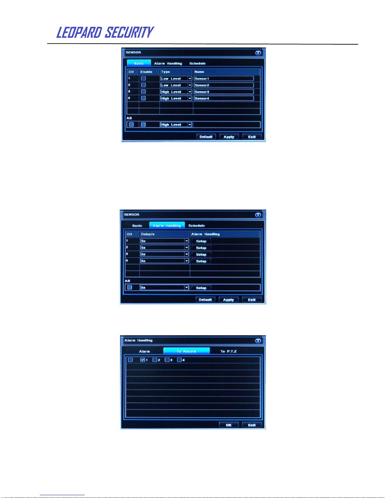
Pic 2-17 Sensor - Basic
Enable sensor alarm and set the alarm type according to triggered alarm type. Two
option: low level and high level
User can set up all channels with same setting by “All”.
Click “Default” button to resort default setting; click “apply” button to save the setting;
click “Exit” button to exit current interface.
2> Alarm handling and schedule
Pic 2-18 alarm handling and schedule
Select delay time and click set up button. Then a dialog box will pop-up as below:
Pic 2-19 alarm handling -alarm configuration
Page 18
User’s Guide
18
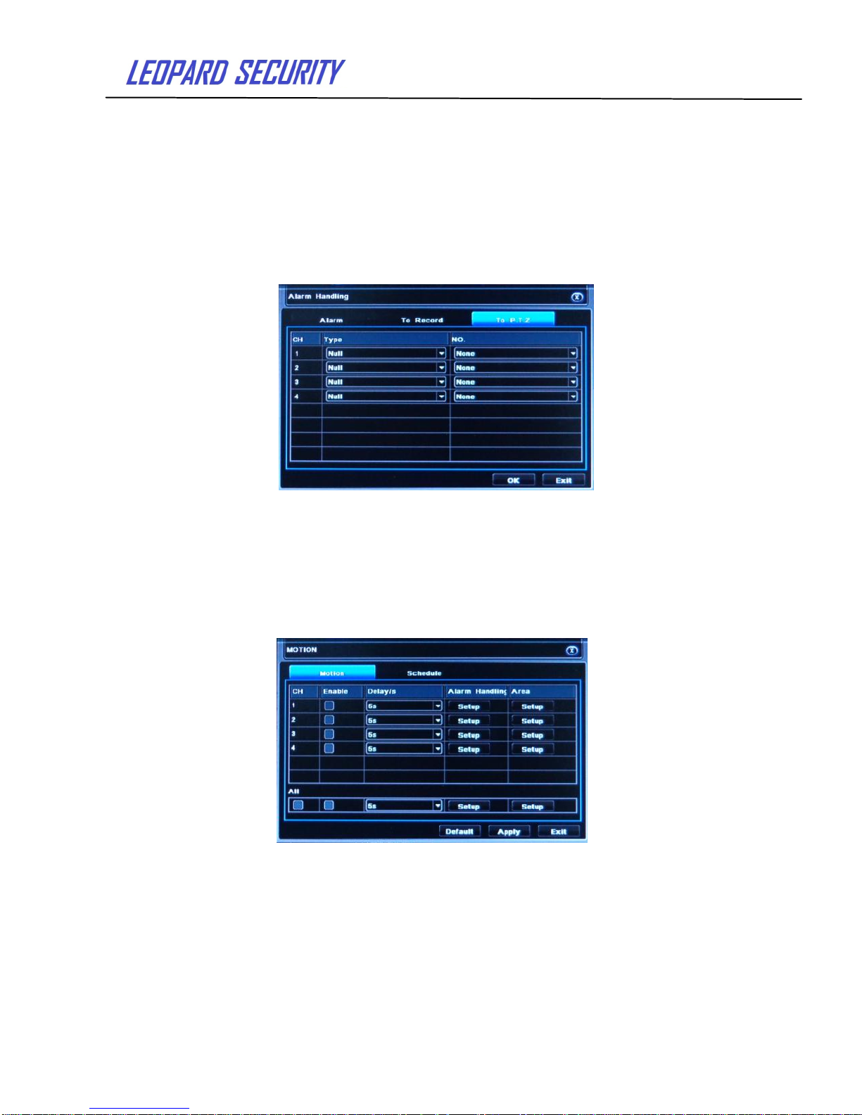
Alarm configuration: in the alarm configuration interface user can choose the alarm
way: audio alarm, big screen alarm, trigger alarm and e-mail alarm
Trigger recording (To Record): check the trigger channel at
"trigger video" interface. Click "OK" to save the above settings, click "Exit" to exit the
current interface channel.
Alarm linkage (To PTZ): set the alarm type and linkage type at linkage
alarm interface, such as preset points, cruise line or track (Note: these three are already
applicable before PTZ configuration). Click "OK" to save above setting.
When the corresponding channel gets alarm input, PTZ starts up the preset points,
cruise lines and track. Click "Exit" to exit the current interface.
Pic 2-20 Alarm handling - alarm linkage
User can set up all channels with same setting by checking “All”.
Click “Default” button to resort default setting; click “Apply” button to save the setting;
click “Exit” button to exit current interface.
2.4.5.2 Motion
Motion includes two submenus: Motion and Schedule.
1> Motion
Pic 2-21 Motion
Click to enable motion alarm and set alarm delay time. It refers to the delay time to
preset time after disable the motion alarm. Click alarm "Setup" button, show below window:
Page 19
User’s Guide
19
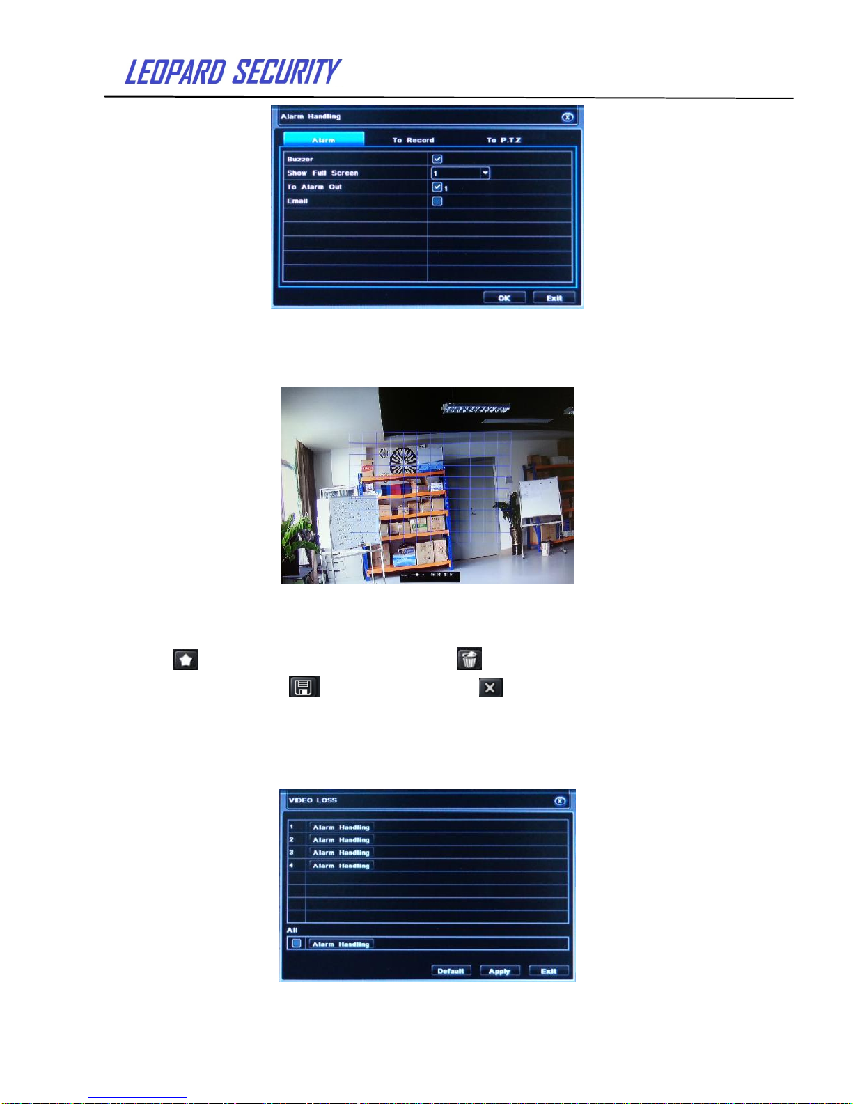
Pic 2-22 Alarm handling
Alarm configuration, trigger video alarm and linkage alarm handling are as same as
sensor alarm handling settings.
Click on "Area Setup" button at Motion detection interface and turn to the
following window:
Pic 2-23 Motion detection - Area Setting
At area setting interface, users can adjust the sensitivity value (1-5) and the
default value is 4. 1-5 sensitivity increase gradually. Because sensitivity influenced
by the color of time (day or night), the users should adjust according to actual situation.
click icon, set all for the detection area; click icon,will clear setting
detection region;click icon,save setting;click button, exit from current interface.
User can set up all channels with same setting by checking “All”.
Click “Default” button to resort default setting; Click “Apply” button to save the setting;
click “Exit” button to exit current interface.
2.4.5.3 Video loss
Pic 2-24 Video loss
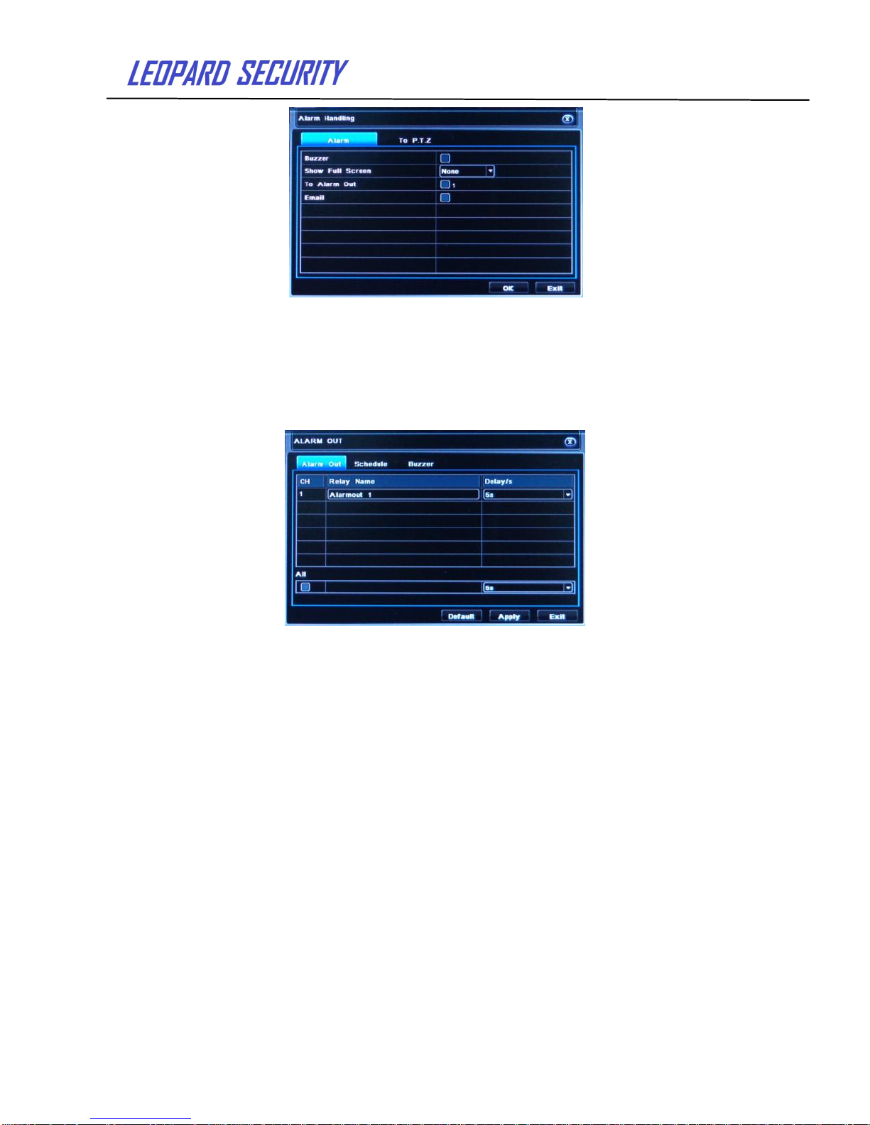
Click“Alarm handling”button and turn to window as below:
Page 20
User’s Guide
20
Pic 2-25 Video loss - alarm handling
The set up steps of video loss trigger are familiar with alarm handling. Disconnected
from the network: when the network connection is disconnected, the system will
automatically sent E-mail to the user specified mailbox about the network disconnected.
2.4.5.4 Alarm out
Alarm out includes three submenus: alarm out, schedule and buzzer.
1> Alarm out
Pic 2-26 Alarm out
In this interface, user can set alarm out name and select delay time.
User can set up all channels with same setting by checking “All”.
Click “ Default” button to resort default setting;click “Apply” button to save the setting; click
“Exit” button to exit current interface.
2> Buzzer
At buzzer interface, check Buzzer function and set buzzer alarm hold time.
2.4.6 Network configuration
Network configuration includes four submenus: network, sub-stream, Email and other
setting.
2.4.6.1 Network
Page 21
User’s Guide
21
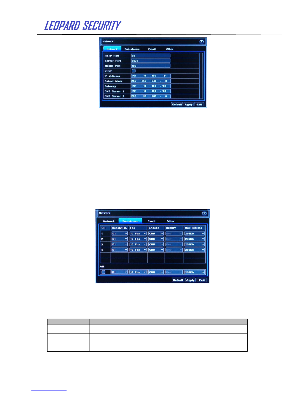
Pic 2-27 Network configuration
HTTP port:the default value is 80. If the value changed, user needs to add the port
number when typing IP address in IE address blank. If set HTTP port to 82, IP address:
http://192.168.0.25. User needs to input that address: http://192.168.0.25:82 into IE
browser.
Server port: data and image communication port number.
After select the "Obtain an IP address automatically", the device will distribute IP
address, subnet mask, and gateway IP and DNS server.
Enable PPPoE to directly connect the DVR to internet via ADSL and then input the
user name and password; click TEST button to test the effectiveness of the relevant
information.
Click “Default” button to resort default setting;click “Apply” button to save the setting;
Click “Exit” button to exit current interface.
2.4.6.2 Network Sub stream
Pic 2-28 Network Sub stream
Select fps, resolution, quality and Max Bit rate. User can also set up all channels with same
Setting.
Click “Apply” button to save the setting; click “Exit” button to exit current interface.
Parameter
Meaning
FPS
Range from: 1-30(NTSC)1-25(PAL)
Resolution
Support D1
Quality
The higher the value is, the record image is clearer. Six options:
lowest, lower, low, medium, higher and highest.
Page 22
User’s Guide
22
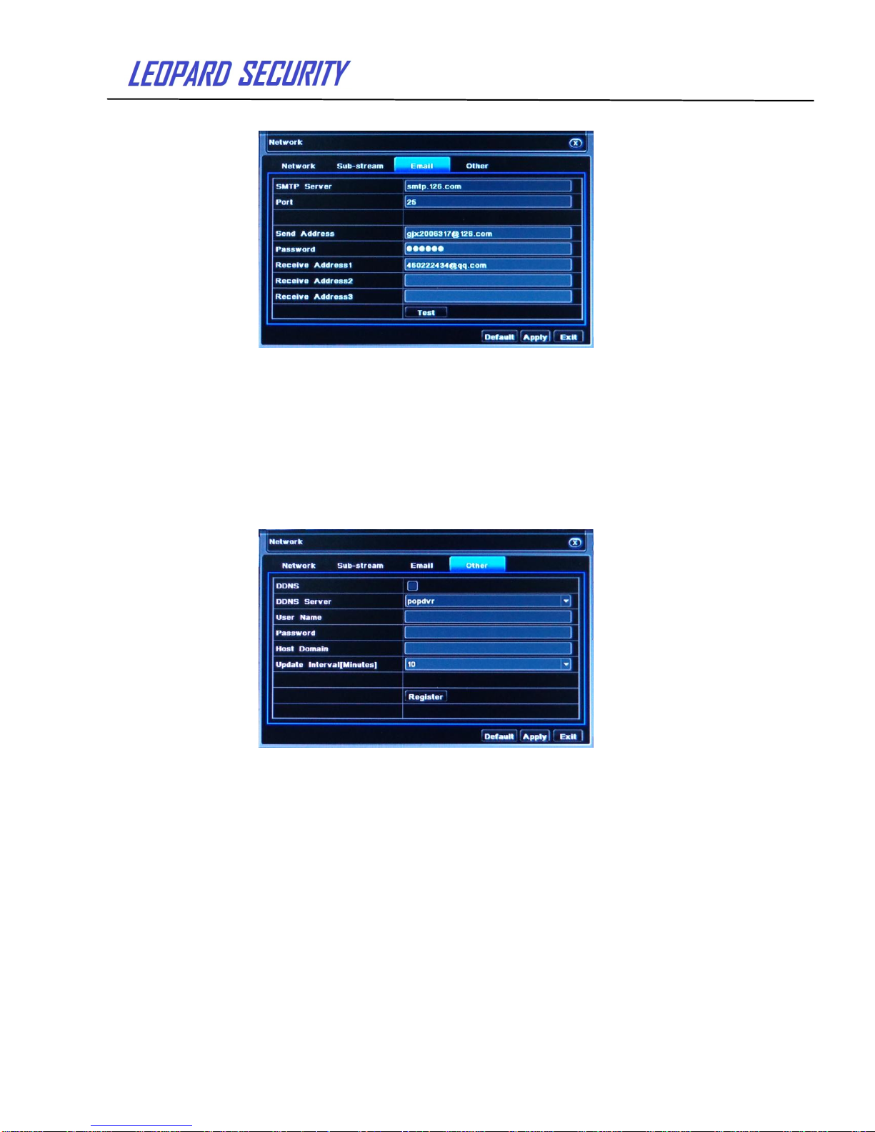
2.4.6.3 Email
Pic 2-29 Email
SMTP Server/Port: the name and port number of SMTP server.
Send address/password: sender’s email address/password.
Receive address: receiver’s email address. Here user can add at least three mail
addresses.
Click Test button to test the validation of the mailbox.
Click “Default” button to resort default setting;click “Apply” button to save the setting;
click “Exit” button to exit current interface.
2.4.6.4 Other settings
Pic 2-30 Other settings
Enable DDNS server: user needs to input user name, password and host domain
name of the registered website. Click TEST to test the effectiveness of the relevant
information. Click “Default” button to resort default setting; click “Apply” button to save the
setting; click “Exit” button to exit current interface.
Note: the user select a domain name which is bound by the Domain Name Service for
DVR. You must first register user name and password on the website of the ISP. And
then apply for a domain name for the server online. After the application is successful, the
user could enter the domain name to access the server from IE.
2.4.7 User management
Page 23
User’s Guide
23
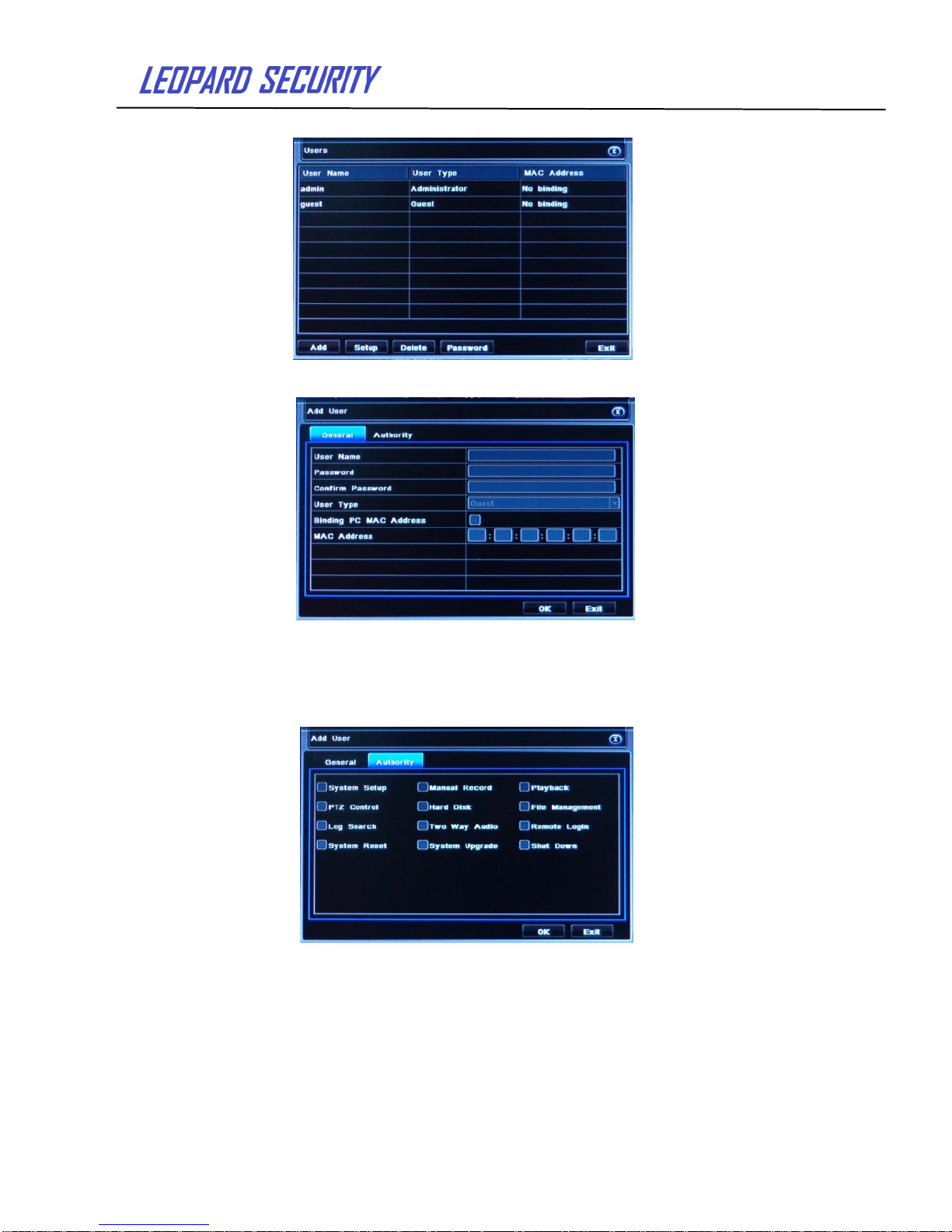
Enter User management , as below picture:
Pic 2-31 User management
Click Add button and a dialog box will pop-up as below:
Pic 2-32 General
① General: Input user name, password; select user type; input the MAC address of
the PC; click OK button. This user will be added into the user list box. Click Exit button to exit
the current interface.
② Authority:
Pic 2-33 Authority
In the authority interface, can assign the definite operation authority of that user.
In the user management interface, click Setup button to modify user name, user type
and binding PC MAC address.
Select the user needs to be deleted in the user list box and then click “Delete” button
to delete this user. Click change password button to modify the password and then click
“Exit” button to exit the current interface.
Page 24
User’s Guide
24
2.4.8 P.T.Z configuration
P.T.Z configuration includes two submenus: serial port and advanced.
2.4.8.1 serial port
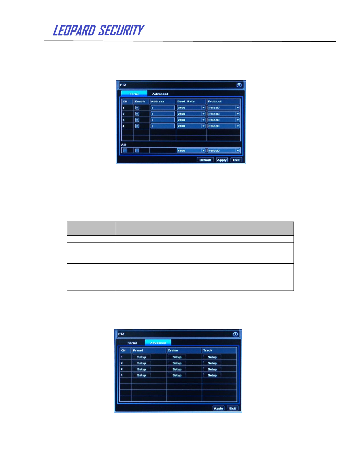
Pic 2-34 Serial port
Click“Enable”,base on P.T.Z support Protocol to set Address, Baud rate and Protocol.
User can set up all channels with same serial port setting by checking “All”. click
“Default” button to resort default setting; click “Apply” button to save the setting; click “Exit”
button to exit current interface.
Definitions and descriptions of serial port:
2.4.8.2 Advance PTZ configuration
Pic 2-35 Advance
Parameter
Meaning
Address
The address of the PTZ device
Baud rate
Baud rate of the PTZ device. Options form: 110, 300, 600, 1200,
2400, 4800, 9600, 19200, 34800, 57600, 115200, 230400,
460800, 921600.
Protocol
Communication protocol of the PTZ device. Options from:,
PELCOP, PELCOP1, PELCOP5, PELCOD, PELCOD1, HY,
PHILIPS, SAMSUNG SHARP,SONY, SAMSUNG, PANASMIC ,
CONTROLl, etc…
Page 25
User’s Guide
25
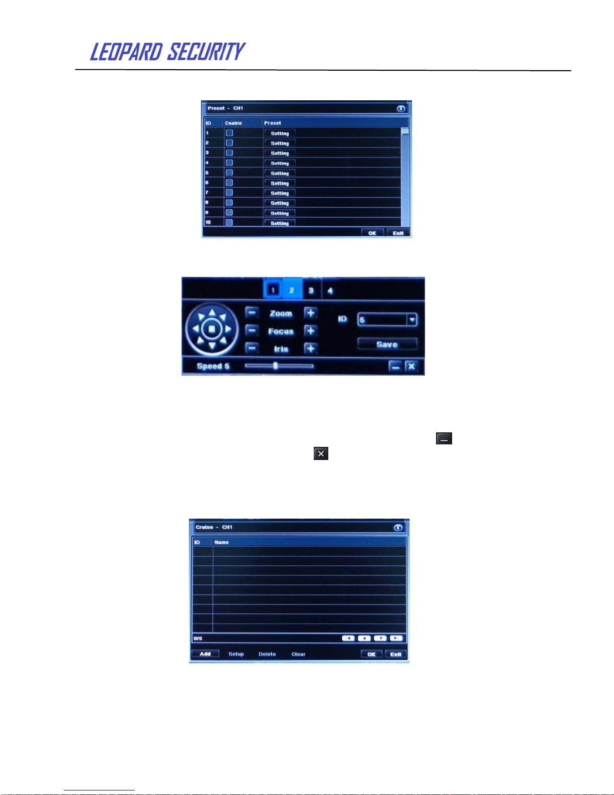
In the Advance interface, after click preset “Setup” button, a dialog box will pop-up as
below:
Pic 2-36 Preset point setting
In the preset point interface, click Setting button to see a window as below:
Pic 2-37 Preset setting
User can control the P.T.Z up, up left, down, right down, left , left down, right and up
right and stop rotating;can adjust the rotation speed of the PTZ, focus and aperture;choose
preset point's serial number. Click “Save” button to save the settings; click icon to hide
the tool bar and right click to recovery it;click icon to exit the current interface.
In the preset interface, click ”OK” button to save the setting; click ”Exit” button to exit
current interface.
In the Advance interface, click cruise “Setup” button and a dialog box will pop-up as
below:
Pic 2-38 Advance - cruise “Setup”
Click Add button to add cruise line(max 32 cruise line can be added); select a cruise
line and click Setup button, to see a window as below:
Page 26
User’s Guide
26
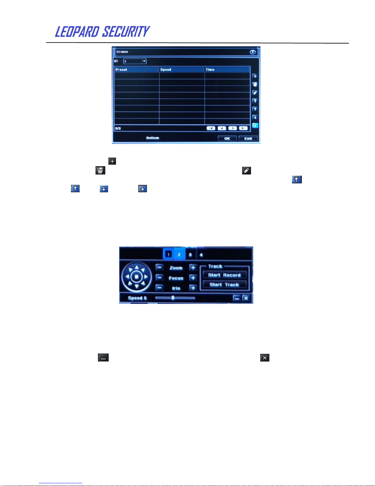
Pic 2-39 Cruise set - preset point setting
Click Add icon,to set the speed and time of preset point. Select a preset point and
click Delete icon to delete that preset point. Click Modify icon to modify the setting
of a preset point. User can click those icons to adjust the position of preset point. top 、
up 、down and bottom .Click Preview button to preview the cruise line and then click
“OK” button to save the setting. Next, click “Exit” button to exit current interface
Select a preset point in the cruise line list box and click Delete button to delete that
cruise line; click “Clear all” button to clear all cruise line from the list box; click “OK” button to
save the setting; click “Exit” button to exit current interface.
In the Advance interface, click track “Setup” button to pop up a dialog box as below:
Pic 2-40 Track setting
User can control the PTZ rotates up, up left, down, right down, left, left down, right and
up right and stop rotating. Adjust the rotate speed and the value of zoom, focus and iris of
the dome. Click Start Record button to record the move track of PTZ and click this button
again can stop record;click Start track button to play recorded track and click this button
again can stop play . The user can drag the slider to adjust the speed of P.T.Z movement.
Click icon to hide the tool bar, right-key can remerge it; click icon to exit the
current interface.
In the Advance interface, click “Default” button to resort default setting; click “Apply”
button to save the setting; click “Exit” button to exit current interface.
Page 27
User’s Guide
27
2.4.9 Advance configuration
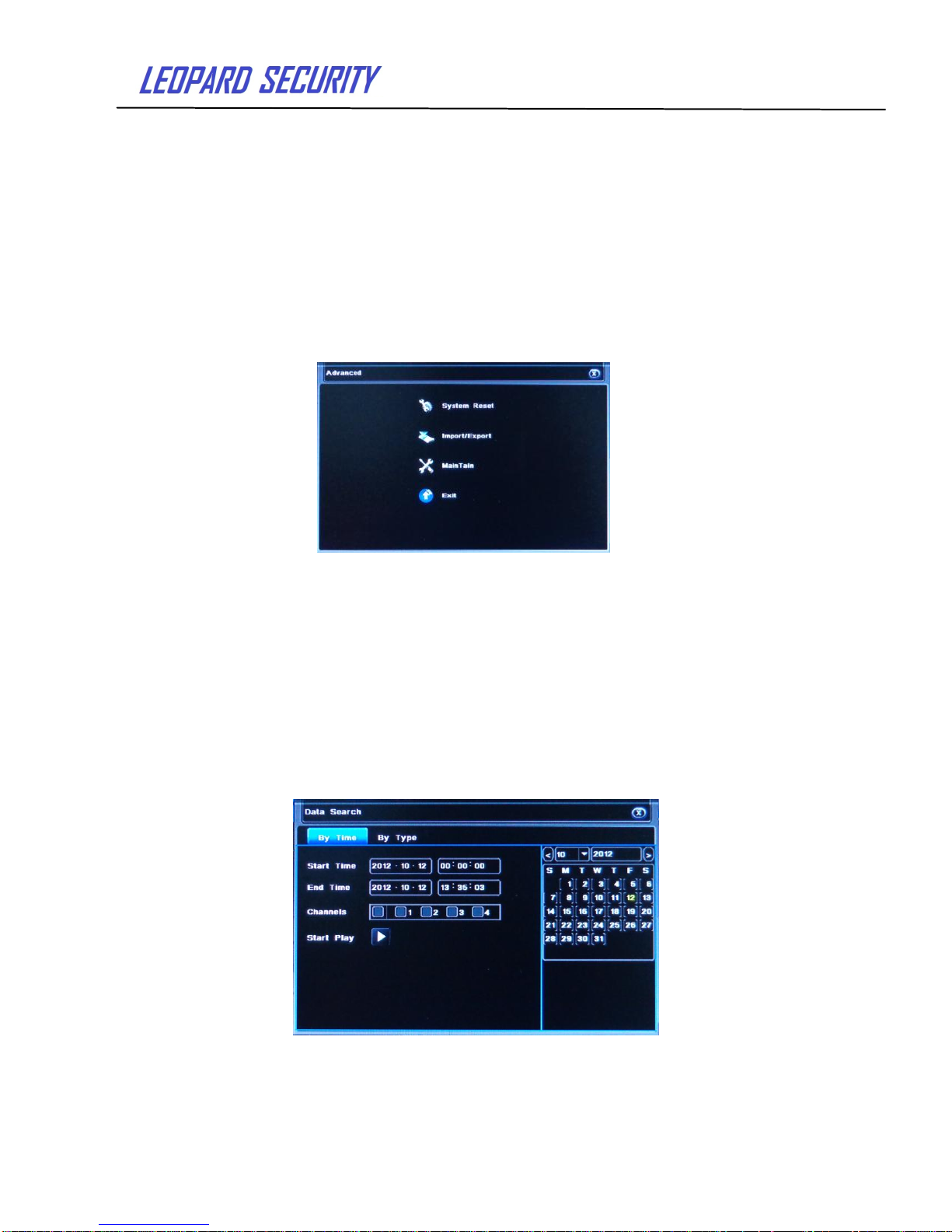
Advanced settings include four submenus: System Reset, Import / Export , Maintain
and Exit.
1. System Reset: reset all setting back to factory settings.
2. Import / Export: Users can export data files to back up on removable storage
devices. You can also import the specified data file from a removable storage device to a
DVR.
3. Maintain
4. Exit: exit current interface.
Pic 2-41 Advance configuration
Return to the main menu and enter the data retrieval interface.
2.5 Data retrieval
Search configuration includes two submenus: Time Search, Event Search,
2.5.1 Time search
Step1:Enter into Search configuration Time Search; refer to below picture:
Pic 2-42 Time search
Page 28
User’s Guide
28
Step 2:Select the channel, the calendar date , the start time and end time.
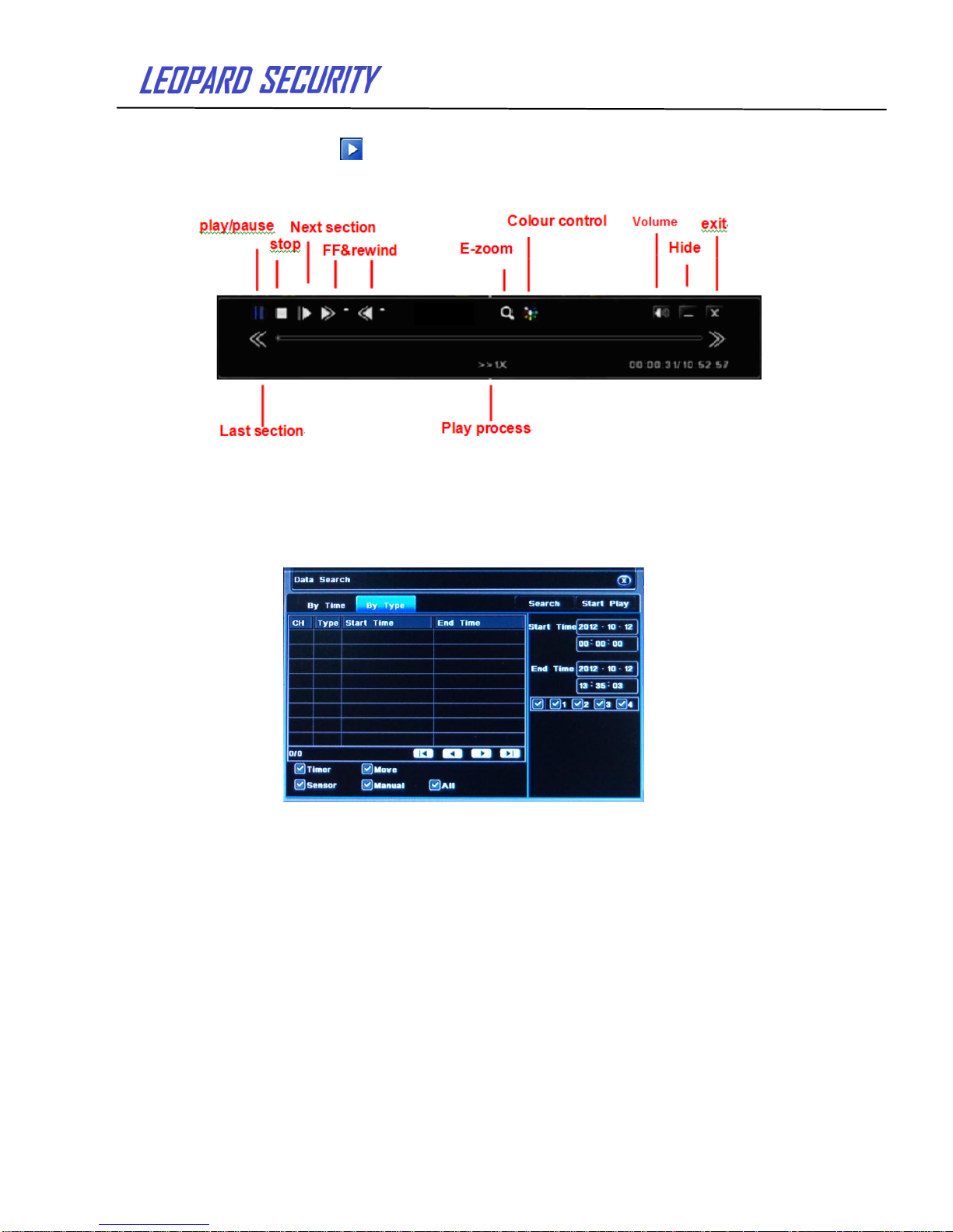
Step 3:Click“Play” button and playback will start from the set time. Click the
corresponding button on the screen to start the operations.
Pic 2-43 Playback buttons
2.5.2 Event search
Step1::Enter into Search configuration event search; refer to below picture:
Pic 2-44 Event search
Step2:After clicking Search button, the searched event information will displayed in
the event list box. Double check a certain record file to playback.
Step3:User can select date, channel, and check Motion, Sensor or All to search.
Page 29

User’s Guide
29
2.6 Backup
This function supports data backup by USB device. User also can make remote
backup by IE browser via internet.
Step1: Enter into backup configuration interface, as below picture:
Pic 2-45 Data backup
Step2: Set the start & end time, select channels and click Search button to display the
searched data in the data backup list box.
Step3: Select a data file or check “All” to select all data files, then click “Backup”
button,
Step4: In the backup information interface, user can check the relevant information of
backup files, storage type and save file type etc. Click “Start” button to starting backup.
2.7 Check information
Through this option, the user can check system information, system journal and
network information.
System Information:
Enter menu View information System information. In the interface user can view
the equipment and version information and relevant information
System Journal:
Enter menu View system information Log information. In the interface users can
set the start & end time of log you want to view or select the type of log you want to view.
Click the search button, the searched log information will be displayed in the log list box.
Note: Users can export data files to back up on removable storage devices.
Network information:
Enter menu View information Network configuration,in the interface,Users
can view the relevant parameters of the network information .
2.8 Disk management
Enter menu Disk management. In the interface, the user can
view disk storage state, also can choose to format the hard disk.
Please format the hard disk before record ,Specific operation as below:.
Step1: Enter into disk management interface. The system will pop up the Disk
Management window.
Step2: Select a hard disk and click Format button to star format. Set the property of the
disk then click “Apply” button to save the setting.
Note: All recorded files in the hard disk will be lost after formatted.
Page 30

User’s Guide
30
2.9 Upgrade
Once have the new version, the user can choose to upgrade the panel and the main
board. User can get upgrade software from the vendor to upgrade the system.
Upgrade step:User needs to copy the upgrade software which get from vendor into
the USB storage device and then connect to the USB port. Enter Menu Upgrade and refresh
list. The upgrade software name is displayed on the upgrade list box, select that software and
click Upgrade button to start upgrading. System will automatically restart during the upgrade
process. Please wait for a while when the system reboot. Please don’t cut off power during
upgrading. This system supports the upgrade of the USB device but it must be
compatible with the USB device. It needs to reboot the system after the upgrade complete to
take effect.
Note: If the upgrade software does not appeared in USB, usually the USB device is
not compatible.
2.10 Log off
Enter Menu Log off,Click Log off icon, The system will exit the current user login. If
user wants to log in again, click main menu icon to enter into user name and password to
re-login.
2.11 System shut down
Click “system shut down” icon to shut down the system.
 Loading...