

Page 1

Network / IP Camera
Quick Start Guide
Model: LNCQ111
LNCQ112
LNCQ121
LNCQ122
Page 2

Leopard Imaging Inc.
1130 Cadillac Ct.
Milpitas, CA 95035
Phone: (408) 263-0988
Fax: (408) 217-1960
Web: www.leopardimaging.com
- 2 -
Product Overview
LNC IP camera is the next-generation IP Camera. It outputs full HD Video in
H.264, MPEG-4, MJPEG and other video format at 30 frames per second through the
network. The Graphic Processing Unit supports noise suppression, wide dynamic
range, image enhancement and lens distortion correction, which makes clear images
achievable even under high-contrast, low-light environment. The LNC IP camera is
ONVIF compliant and can be easily integrated into security systems.
Package contents
1. LNC IP Camera (1)
2. 12V DC Power Adapter (1)
3. User’s Guide (1)
4. Mounting bracket (1)
5. Certificate and Warranty Card (1)
Optional Accessory
1. Tripod Mount
Page 3
Leopard Imaging Inc.
1130 Cadillac Ct.
Milpitas, CA 95035
Phone: (408) 263-0988
Fax: (408) 217-1960
Web: www.leopardimaging.com
- 3 -
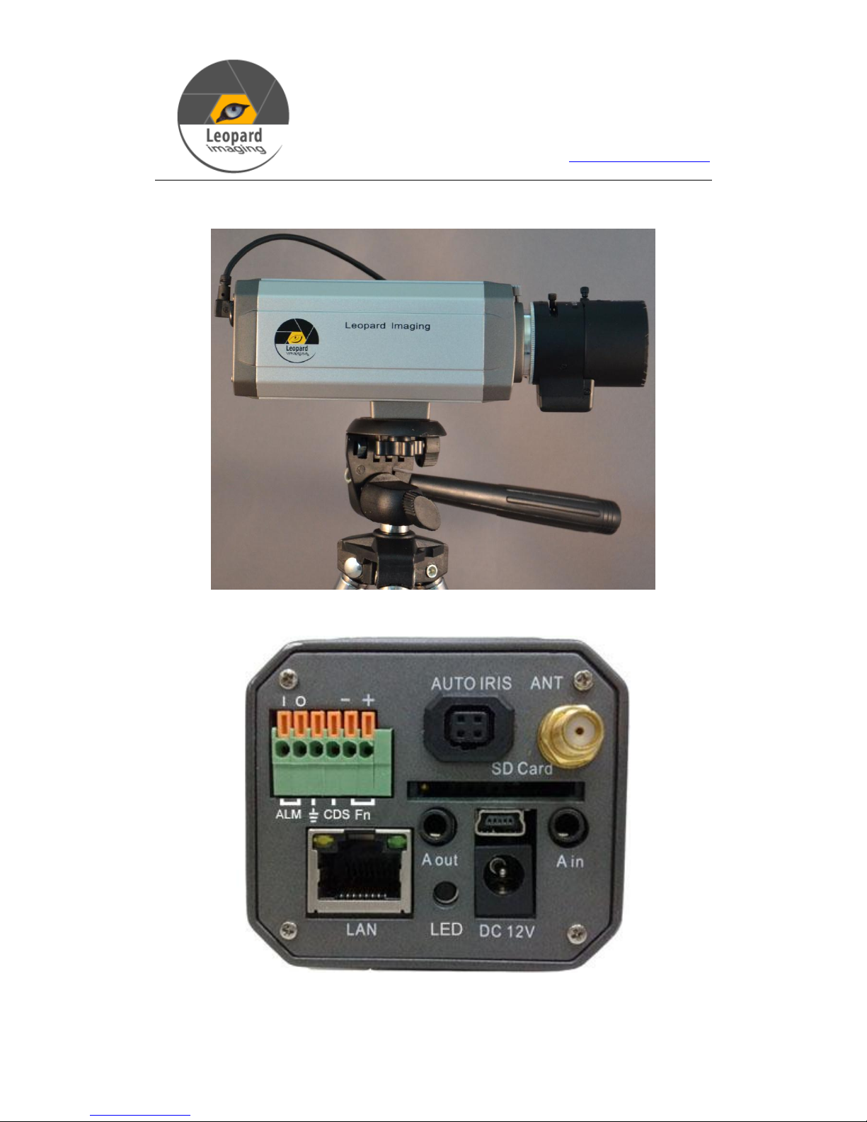
Product View
LNC IP camera Exterior View
LNC IP camera Rear View
Page 4
Leopard Imaging Inc.
1130 Cadillac Ct.
Milpitas, CA 95035
Phone: (408) 263-0988
Fax: (408) 217-1960
Web: www.leopardimaging.com
- 4 -
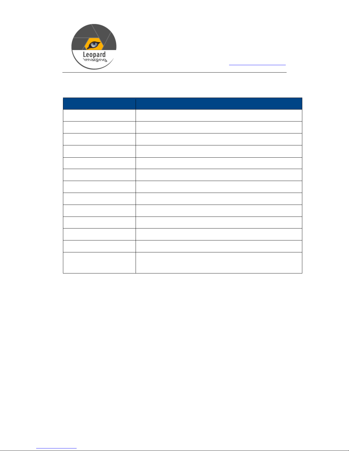
LNC IP camera Interface Description
Interface
Description
LAN
RJ45 LAN Connector
LED
Power Indicator
DC 12V
Power Input DC 12V/1A
A out
Audio output
A in
Audio input
SD Card
SD card slot
Mini USB
USB interface
AUTO IRIS
Auto iris lens contact, (Support DC lens)
ANT
Wireless LAN interface
ALM out
Alarm output
ALM in
Alarm input (low level)
GND
Ground
RS485
RS485 control, left RS485(-), right RS485(+) . PTZ decoder
can be connected to support multiple PTZ protocol.
Page 5

Leopard Imaging Inc.
1130 Cadillac Ct.
Milpitas, CA 95035
Phone: (408) 263-0988
Fax: (408) 217-1960
Web: www.leopardimaging.com
- 5 -
Installation
Notice
The LNC IP Camera and the Client PC needs to connected to the same routing
device (such as Router, switch etc) or to each other.
Please make sure the DC Adapter or POE is correct.
When connecting the alarm input, please make sure the input DC level is lower
than 5V.
Installation Procedure
1. Connect the Network cable to the network device or directly to the client PC.
2. Connect the 12V DC adapter.
3. After connecting the DC power, the LED indicator will be turned on. The
Network Connection indicator (Green LED) will turn on after five seconds.
The data indicator (Orange LED) will blink, which shows that the physical
network connection of the IP Camera is finished.
System Configuration
The LNC IP Camera can be managed and maintained via the Web Interface. Prior to
logging on to the Web interface, please make sure:
LNC IP Camera has a network connection and the power is on.
When configured for the first time, the Client PC and the IP Camera must be on
the same network.
It is recommended to use the Microsoft Internet Explorer 6.0 or higher version,
preferably IE 8.0.
If the client PC is running Windows XP, please make sure the UPnP is enabled.
Page 6

Leopard Imaging Inc.
1130 Cadillac Ct.
Milpitas, CA 95035
Phone: (408) 263-0988
Fax: (408) 217-1960
Web: www.leopardimaging.com
- 6 -
To log onto the Web Interface
Double click the UPnP device icon for the IP Camera;The Web Interface will
show up in the Internet Explorer. (The Internet Explorer needs to be the default
browser)
Enter the username and password and the Preview interface will show up. The
default username is “admin” and the password is “admin”.
Note:
1.When running the Web Interface for the first time, the Internet Explorer will remind
you to install the ActiveX and use the Add-ons. Please follow the instructions
when installing the ActiveX.
2.It is recommended to Add/Manage the user account using the Web Interface so the
user does not have to log in as admin every time.
3.After logging on to the Web Interface, users can configure the parameters of the IP
Camera. For detailed info, please refer to the User Guide.
4. For the Spec and FAQs about LNC IP camera, please refer to the User Guide.
 Loading...