

Page 1

Leopardboard
365
Hardware Guide
Rev. 1.0
Page 1
Leopardboard 365
Hardware User
Rev. 1.0
Feb 24, 2010
Guid
e
Page 2

Leopardboard
365
Hardware Guide
Rev. 1.0
Page 2
Leopardboard.org provides the enclosed product(s) under the following conditions:
This evaluation kit is intended for use for ENGINEERING DEVELOPMENT, DEMONSTRATION, OR
EVALUATION PURPOSES ONLY and is not considered by Leopardboard.org to be a finished end-product. Persons
handling the product(s) must have electronics training and observe good engineering practice standards. As such, the
goods being provided are not intended to be complete in terms of required design-, marketing-, and/or manufacturingrelated protective considerations, including product safety and environmental measures typically found in end products
that incorporate such semiconductor co
The kit can’t be returned, it can be exchanged if it is defect.
The user assumes all responsibility and liability for proper and safe handling of the goods; it is the user’s responsibility to
take any and all appropriate precautions with regard to electrostatic discharge.
Leopardboard.org assumes no liability for the changes to this document without notice, customer product design,
software performance, no guarantees as to the correctness or accuracy of the information provided in this
document. For additional information on Leopardboard.org environmental and/or safety programs, please visit
Leopardboard.org.
No license is granted under any patent right or other intellectual property right of Leopardboard.org covering or relating to
any machine, process, or combination in which such Leopardboard.org products or services might be or are used.
mponents or circuit boards.
WARRANTY: The Leopardboard 365 is warranted against defects in materials and workmanship for a period of 30
days from purchase. This warranty does not cover any problems occurring as a result of improper use, modifications,
exposure to water, excessive voltages, abuse, or accidents. All boards will be returned via standard mail if an issue is
found. If no issue is found or express return is needed, the customer will pay all shipping costs.
Mailing Address:
Leopardboard.org
47061 Warm Springs Blvd
Fremont, CA 94539
USA
Page 3

Leopardboard
365
Hardware Guide
Rev. 1.0
Page 3
1.What’s incl
uded
…………………………………………….…....................…………...........4
1.1 Leopardboard 365…………….
1.2 Optional P
1.2.1 Serial Cable……………………………………….....................…………………………………….6
1.2.2 +5V DC Power Adapter……………………………........................……………………………..7
1.2.3 Mini-B USB Cable……………………......................................…………………………………8
1.2.4 Composite Video Cable……………………………....................………………………………..9
1.2.5 Camera Boards………………………………………………...................……………………….10
1.2.6 DVI Board………………………………………………………....................……………………..19
1.2.7 Video Input Board…………………………………..................………………………………..20
1.2.8 HD Component Video Input Board……………................…………………………………21
1.2.9 Component Video Adapter…………………………………………....................……………22
1.2.10 Cam Flex Cable………………………………………………………….....................………….23
1.2.11 24-Pin Flex Cable....................................................................................................24
arts……………………....................………………………………………………………………..
2.
2.1 Leopardboard 365 Feature
2.2 Leopardboard 365 Functional B
2.3 DM365 Proce
2.4 Flash
2.5 DDR2
2.6 Camera
2.7 Audio
2.8 Audio O
2.9 JTAG P
2.10 Serial Port:
2.11 USB 2.0 Port and USB Host m
2.12 SD Card
2.13 Power
2.14 Power
2.15 Composite Video Output P
2.16 Component Video O
2.17 Network
2.18 LCD/DVI
2.19 Expansion P
2.20 Reset B
2.21 DIP Switch
Leopardboard
ssor…………..…….………………………………....................…………………………….
Memory…………....................……………………………....……………………………………….
SDRAM......................………………..………………………………………………………………..
In
terface
Input…………………………....................……..…………………………………………………….
utput…………………........................
ort…………………………......................…………………………………………………………….
RS-
Slot…………….....................……………………..……………………………………………….
Manag
Input………………………………….....................……...…………………………………………..
In
terface
In
terface
ort……………………………..……...................
utton………..…………………………….....................…………………………………………….
…………………………………………….……………….....................……….………………
…….......................……………………………………………………..……………….
232………….
ement
…………….....................……………………………………………………………….
…………………………......................…………...…………………………………….
365
s…………………………….......................………...……………………….
…………………….....................………...…………………………………………..
ort…………..……………………...................…………………...………..
utput………………..………………………...................……….....
List of Contents
..................…………………………………………………………………..
Spec
..…………………….......................……………………………………….
ificati
lock……………………........................
ode..............................
on
………………………....................…………..
………………………………………………………………33
………………………………………………36
………………………………………………46
………………………………26
………………42
5
6
25
25
26
28
29
30
32
34
35
38
39
40
41
43
44
48
49
Page 4

Leopardboard
365
Hardware Guide
Rev. 1.0
Page 4
What’s included?
1. This section is a description of what comes in the box when the Leopardboard 365 is
purchased and Optional Parts provided for purchasing. See Figure 1
Figure
1.
Leopardboard
365 in Box
Page 5

Leopardboard
365
Hardware Guide
Rev. 1.0
Page 5
NOTE: Standard package only includes Leopardboard 365; all other optional
parts are sold separately.
1.1
Leopardboard
365, see
Figure 2.
Figure
2.
Leopardboard 365
Page 6

Leopardboard
365
Hardware Guide
Rev. 1.0
Page 6
1.2
Optional Parts
purchased separately
1.2.1
Serial
o Part number: LI-SER-01
Cable, see
o One end is Female DB9 connector
o Another end is 2.5mm Stereo Plug connector
o Cable Length: 70”
,
not
included
Figure 3.
in the
package,
these parts have to be
Figure
3.
Serial Cable
Page 7

Leopardboard
365
Hardware Guide
Rev. 1.0
Page 7
1.2.2 +5V DC
Power Adapter,
see
Figure 4.
o Part number: LI-PS5-01
o Wall Mount AC/DC Switching Power Supply (2-prong)
o Universal AC Input
o Power Input Frequency: 50/60Hz
o DC Output: [email protected]
o Polarization: Positive Center
o Cord Plug: 2.1mm I.D. x 5.5mm O.D. x 12mm Female
o Cable length: 43”
Figure
4. +5V DC
Power Adapter
Page 8

Leopardboard
365
Hardware Guide
Rev. 1.0
Page 8
1.2.3
o Part number: LI-USB-01
o One end: Mini-B
o One end: Type-A
Mini-B
USB Cable, see
Figure 5.
Figure
5.
Mini-B
USB Cable
Page 9

Leopardboard
365
Hardware Guide
Rev. 1.0
Page 9
1.2.4
o Part number: LI-VIC-03
Composite
Video Cable, see
Figure 6
Figure
6.
Composite
Video Cable
Page 10

Leopardboard
365
Hardware Guide
Rev. 1.0
Page 10
1.2.5 Camera
Boards
1.2.5.1 VGA Camera Board, see Figure 7.
o Part number: LI-LBCMVGA
o Sensor: Micron/Aptina 1/11“ CMOS Sensor MT9V113
o # of Pixels: VGA (648 x 488 pixels)
o Output Data Format: YUV (YCbCr)
o Optical Filter: Infrared Coating at 650nm+/-10nm
o Focal Length, F#: f=1.34+/-0.1mm, F2.8+/-5%
o Vertical View Angle: 660
o Focus Distance: 40cm+/-2cm
o Focus Range: 20cm to Infinity
o RoHS Compliance
Figure
7. VGA Camera Board
Page 11

Leopardboard
365
Hardware Guide
Rev. 1.0
Page 11
1.2.5.2
1.3
o Part number: LI-LBCM1M1
Mega-pixel
Camera
Board,
see
Figure 8
o Sensor: Aptina 1/4“ CMOS Sensor MT9M112
o # of Pixels: 1.3Mega (1280 x 1024 pixels)
o Output Data Format: YUV (YCbCr)
o Optical Filter: Infrared Coating at 650nm+/-10nm
o Focal Length, F#: f=4+/-0.1mm, F2.0+/-5%
o Vertical View Angle: 59.30
o Focus Distance: 120cm+/-2cm
o Focus Range: 60cm to Infinity
o RoHS compliance
Figure
8. 1.3M Camera Board
Page 12

Leopardboard
365
Hardware Guide
Rev. 1.0
Page 12
1.2.5.3
2
Mega-pixel
o Part number: LI-LBCM2M1
o Sensor: Aptina 1/4“ CMOS Sensor MT9D112
o # of Pixels: 2Mega (1600 x 1200 pixels)
o Output Data Format: YUV (YCbCr)
o Optical Filter: Infrared Coating at 650nm+/-10nm
o Focal Length, F#: f=3.79+/-0.1mm, F2.0+/-5%
o Vertical View Angle: 610
o Focus Distance: 120cm+/-2cm
o Focus Range: 60cm to Infinity
o RoHS Compliance
Camera
Board,
see
Figure 9
Figure
9. 2M Camera Board
Page 13

Leopardboard
365
Hardware Guide
Rev. 1.0
Page 13
1.2.5.4
3
Mega-pixel
o Part number:
o Sensor: Aptina 1/4“ CMOS Sensor MT9T111
o # of Pixels: 3Mega (2048 x 1536 pixels)
o Output Data Format: YUV (YCbCr)
o Optical Filter: Infrared Coating at 650nm+/-10nm
o Focal Length, F#: f=3.78+/-0.1mm, F2.8+/-5%
o Vertical View Angle: 61.40
o Focus Distance: 120cm+/-2cm
o Focus Range: 60cm to Infinity
o RoHS Compliance
LI-L
BCM3M1
Camera
Board,
see
Figure 10
Figure
10. 3M Camera Board
Page 14

Leopardboard
365
Hardware Guide
Rev. 1.0
Page 14
1.2.5.5
5
Mega-pixel
o Part number: LI-LBCM5M1
Camera
Board,
see
Figure 11
o Sensor: Aptina 1/2.5“ CMOS Sensor MT9P011
o # of Pixels: 5Mega (2592 x 1944 pixels)
o Output Data Format: RGB
o Optical Filter: Infrared Coating at 650nm+/-10nm
o Focal Length, F#: f=6.12+/-0.1mm, F2.8+/-5%
o Vertical View Angle: 60.30
o Focus Distance: 120cm+/-2cm
o Focus Range: 60cm to Infinity
o RoHS Compliance
Figure
11. 5M Camera Board
Page 15

Leopardboard
365
Hardware Guide
Rev. 1.0
Page 15
1.2.5.6 5 Mega-pixel Camera Board, see Figure 12
o Part number: LI-5M03
o Sensor: Aptina 1/2.5“ CMOS Sensor MT9P031
o # of Pixels: 5Mega (2592 x 1944 pixels)
o Pixel Size: 2.2μm x 2.2μm
o Support 720p @ 60 fps
o Pixel Dynamic Range: 70.1dB at full resolution
o Output Data Format: RGB
o RoHS Compliance
Figure
12. LI-5M03
Page 16

Leopardboard
365
Hardware Guide
Rev. 1.0
Page 16
1.2.5.7 WVGA Global Shutter Camera Board, see Figure 13
o Part number:
o Sensor: Aptina 1/3” CMOS Digital Sensor MT9V034
o # of Pixels: VGA (752 x 480 pixels)
o Pixel Size: 6μm x 6μm
o Max Data rate: 27 Mega pixel Per Second
o Frame rate: 60 fps at full resolution
o Responsivity: 4.8 V/lux-sec (550nm)
o Support either M12 lens or CS-Mount lens
o RoHS Compliance
LI-VM34LP
Figure
13. WVGA
Board
Camera
Page 17
Leopardboard
365
Hardware Guide
Rev. 1.0
Page 17
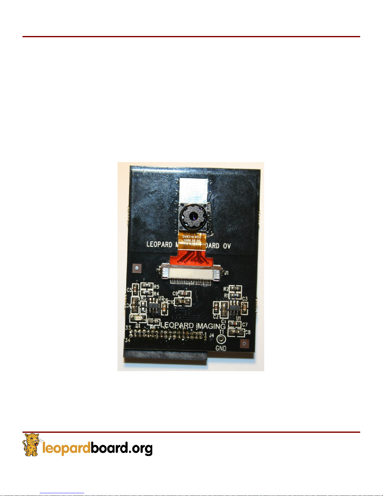
1.2.5.8 Omni Vision 720p Camera Board, see Figure 14
o Part number:
o Sensor: Omnivision 1/4“ CMOS Sensor OV9712
o WXGA (1280 x 800), 30fps
o Pixel size: 3um x 3um
o Output Data Format: 10-bit raw RGB data
o Focal Length, F#: f=3.45+/-0.1mm, F2.8+/-5%
o View Angle: 65.9
o Focus Range: 40cm to Infinity
o RoHS Compliance
LI-
OV
720
Figure
720p Camera Board
14. Omni Vision
Page 18

Leopardboard
365
Hardware Guide
Rev. 1.0
Page 18
1.2.5.9 Omni Vision 1080p Camera Board, see Figure 15
o Part number:
o Sensor: Omnivision 1/3“ CMOS Sensor OV2710
o # of Pixel: 1920 x 1080
o Image size: 1080p @ 30fps
o Pixel size: 3um x 3um
o Output Data Format: 8-/10-bit raw RGB data
o RoHS Compliance
LI-
OV
1080
(Sorry, Figure 15 is currently unavailable)
Page 19
Leopardboard
365
Hardware Guide
Rev. 1.0
Page 19
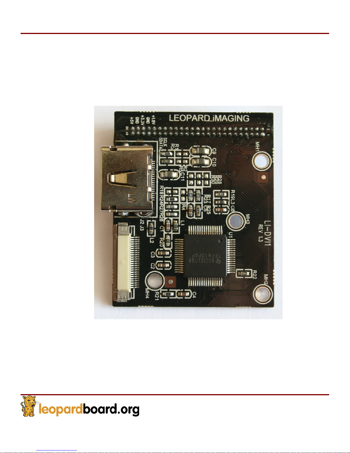
1.2.5.10 DVI board, see Figure 16
o Part number:
o Support standard DVI output
o Pico DLP compatible
o RoHS Compliance
LI-DVI1
Figure
16.
DVI Board
Page 20
Leopardboard
365
Hardware Guide
Rev. 1.0
Page 20
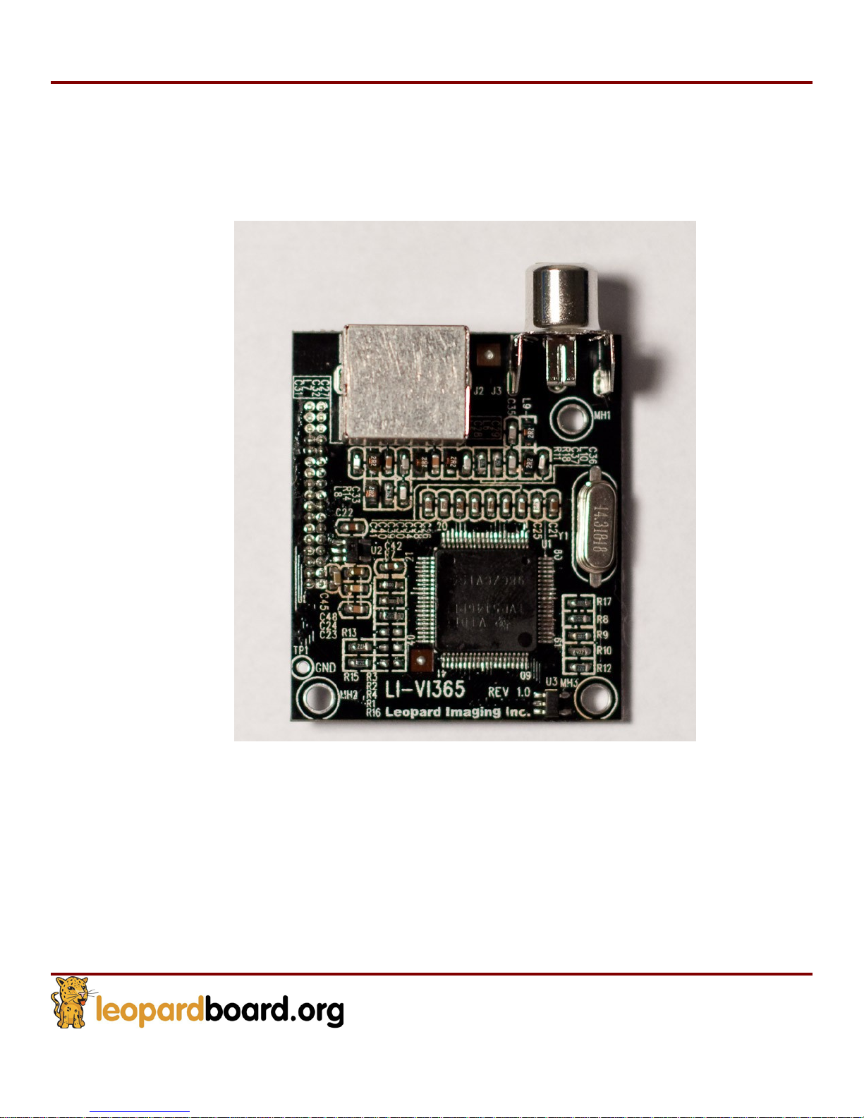
1.2.6 Video Input board, see Figure 17
o Part number:
o Support standard S-video/Composite video input
o RoHS Compliance
LI-VI
365
Figure
17. Video
Input Board
Page 21
Leopardboard
365
Hardware Guide
Rev. 1.0
Page 21
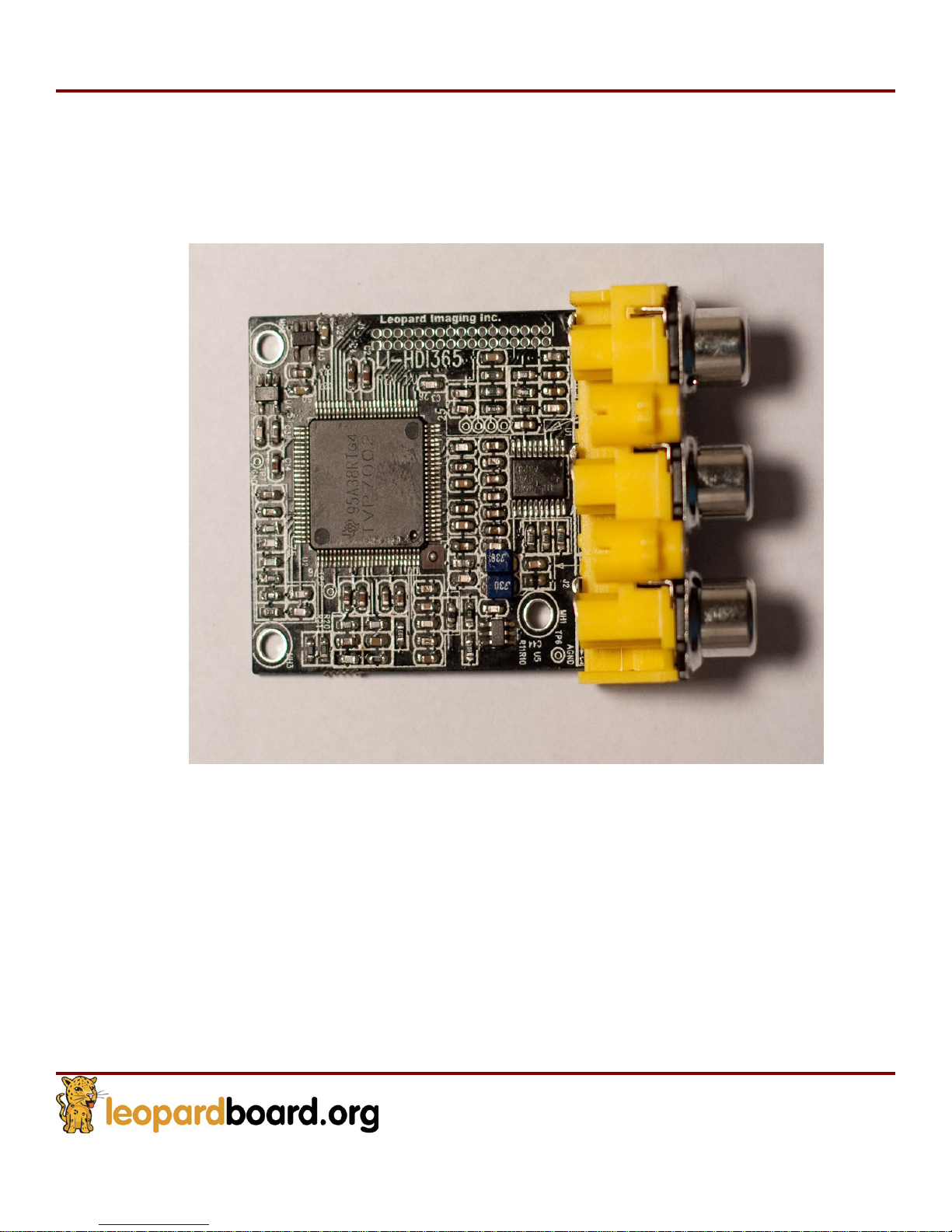
1.2.7 HD Component Video Input Board, see Figure 18
o Part number:
o Support Component Video input
o RoHS Compliance
LI-HDI365
Figure
18. HD Com
Video
Input Board
ponent
Page 22
Leopardboard
365
Hardware Guide
Rev. 1.0
Page 22
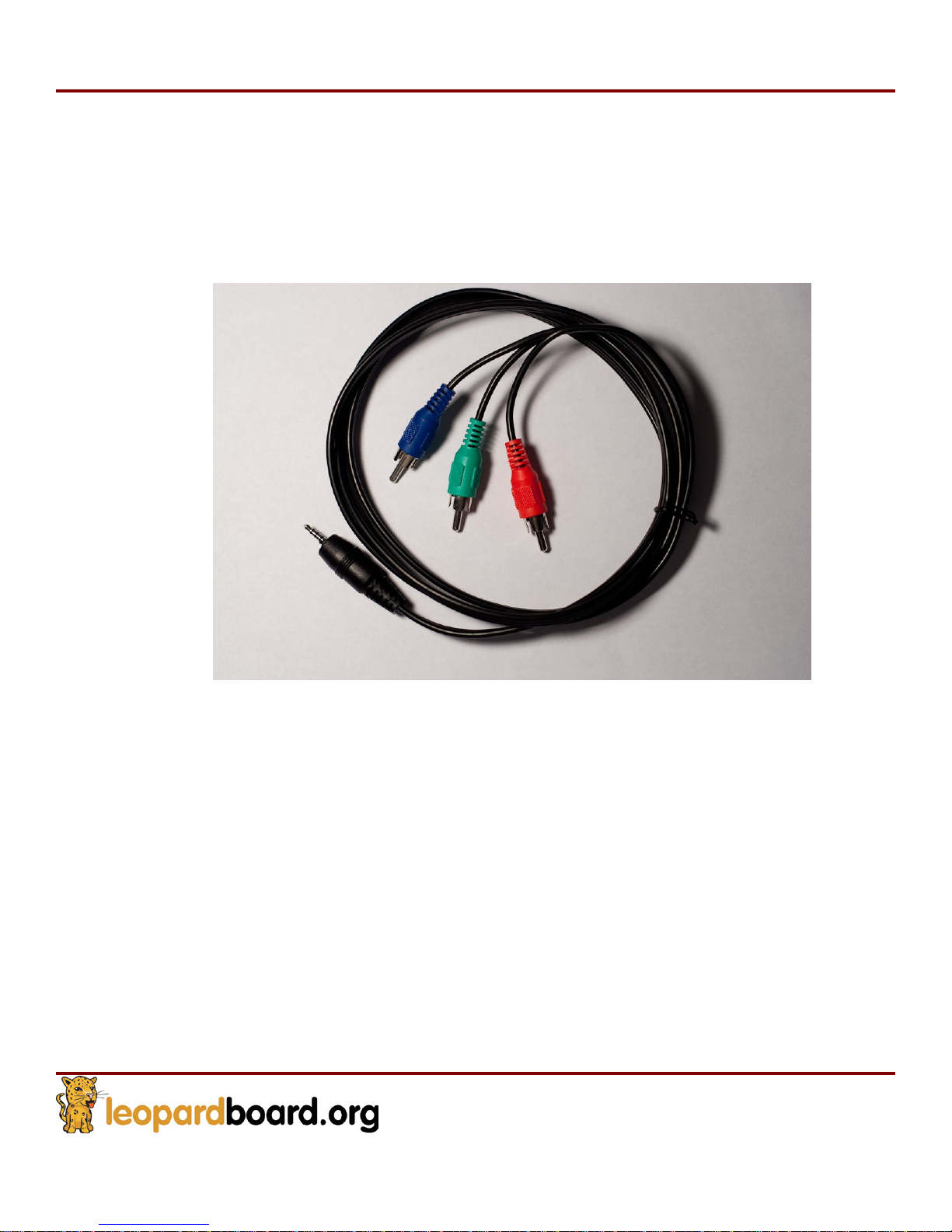
1.2.8 Component Video Adapter Cable, see Figure 19
o Part number:
o Convert Stereo phone jack to Y/Pb/Pr RCA connector
o RoHS Compliance
LI-VI
C-02
Figure
19.
Component Video
Adapter Cable
Page 23
Leopardboard
365
Hardware Guide
Rev. 1.0
Page 23
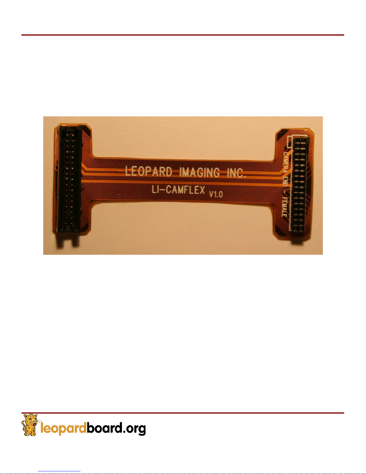
1.2.9 Cam Flex Cable, see Figure 20
o Part number:
o Length: 2”
o Connect between camera board and Leopardboard 365
o RoHS Compliance
LI-CAMFLEX
Figure
20. Cam Flex Cable
Page 24
Leopardboard
365
Hardware Guide
Rev. 1.0
Page 24
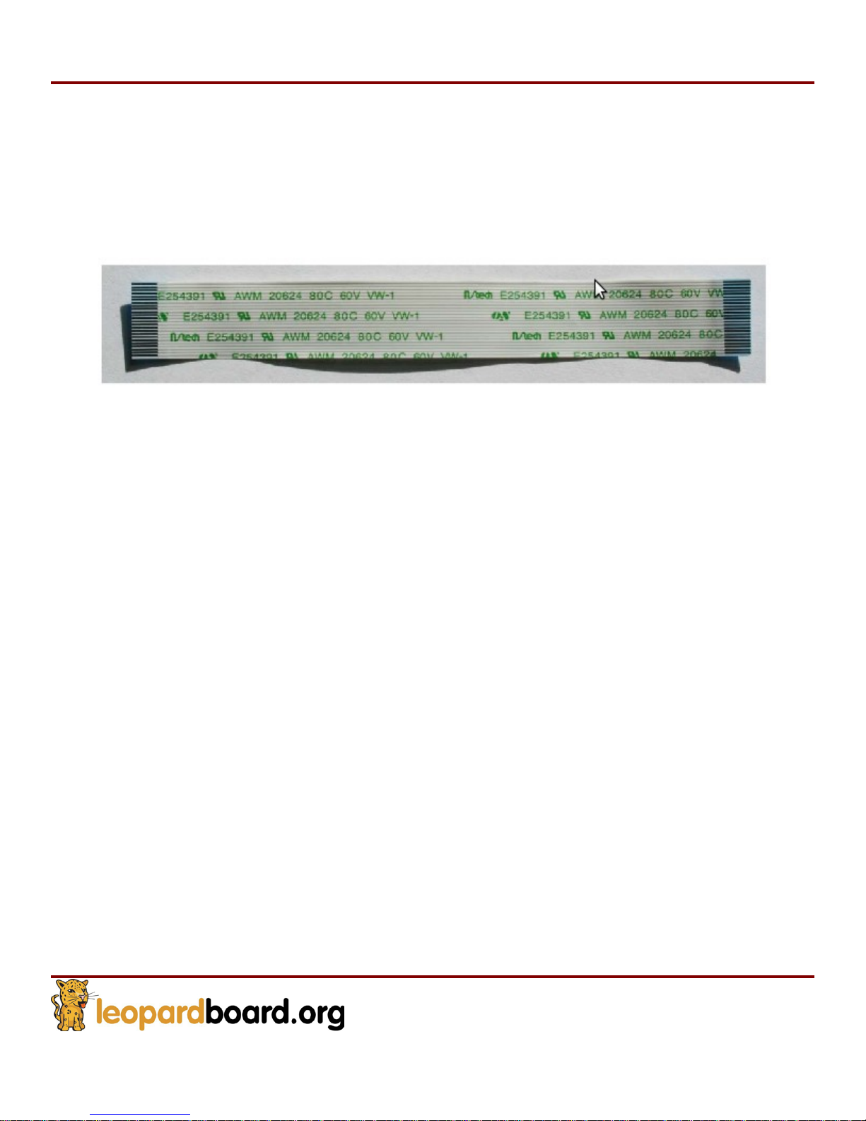
1.2.10 24-pin Flex Cable (Figure 21)
o Part number: LI-FLEX01
o Length: 4”
o Connect between DVI board and Pico Projector.
Figure
21. 24-pin Flex Cable
Page 25
Leopardboard
365
Hardware Guide
Rev. 1.0
Page 25
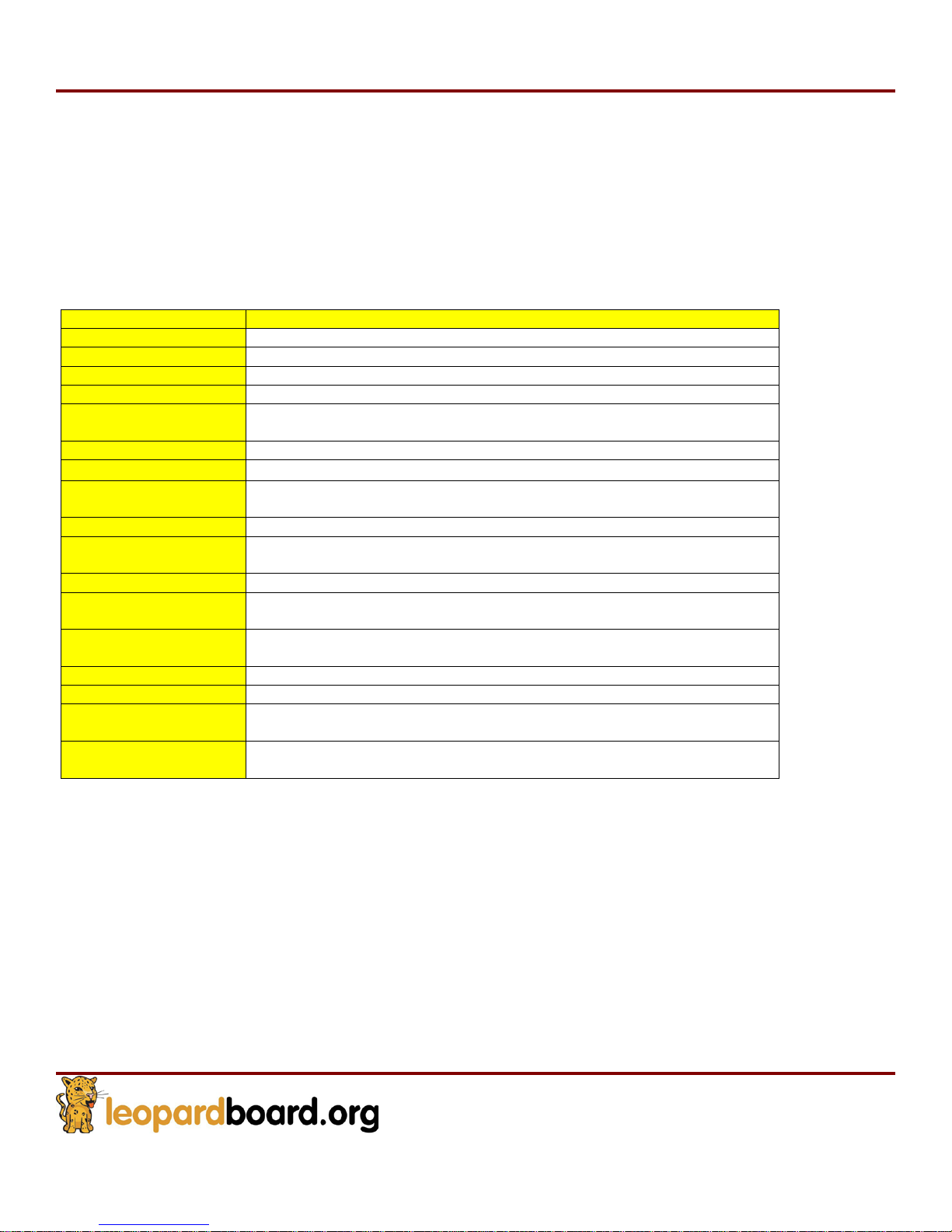
Features
Proce
ssor
TMS320DM365 Processor
NAND Flash
2Gb Micron NAND Flash (256MB)
DDR2
SDRAM
1Gb Micron DDR2 SDRAM (128MB)
Camera Interface
VGA, 1.3M, 2M, 3M and 5 Mega-pixel CMOS Sensors supported
Audio In
/Out
AIC3104 Audio chip, Stereo Audio In/Out, 2.5mm Stereo Plug
connector
JTAG Port
JTAG Debug Port
Serial
Port
RS-
232
UART Debug Port, 2.5mm Stereo Plug connector
USB 2.0 Port
USB 2.0 HS (Device can be powered by USB port), support both
Host and Device Mode
SD Card Slot
SD/MMC Slot
Power
Management
TPS65053 Power management chip
Power Input
+5V Power Input, 2.1mm I.D. x 5.5mm O.D. x 12mm Female
Composite Video
Output Port
PAL/NTSC Output
Component Video
Output Port
HD Component YPbPr Output
Network Interface
10/100 Ethernet
LCD/DVI Interface
LCD/DVI Interface through adapter board
Expansion Port
(Not Populated)
SD/MMC, I2C, UART, McBSP, GPIO, 3.3V power supply
PCB Board
Mechanical
3” x 2.5” (76.2mm x 63.5mm)
Leopardboard 365 Specification
2. This section covers the specifications of the Leopardboard 365 and it also provides a
high level description of the major components and interfaces that make up the
Leopardboard 365.
2.1
Table 1 provides a list of the Leopardboard 365 features.
Leopardboard
365 features
Page 26
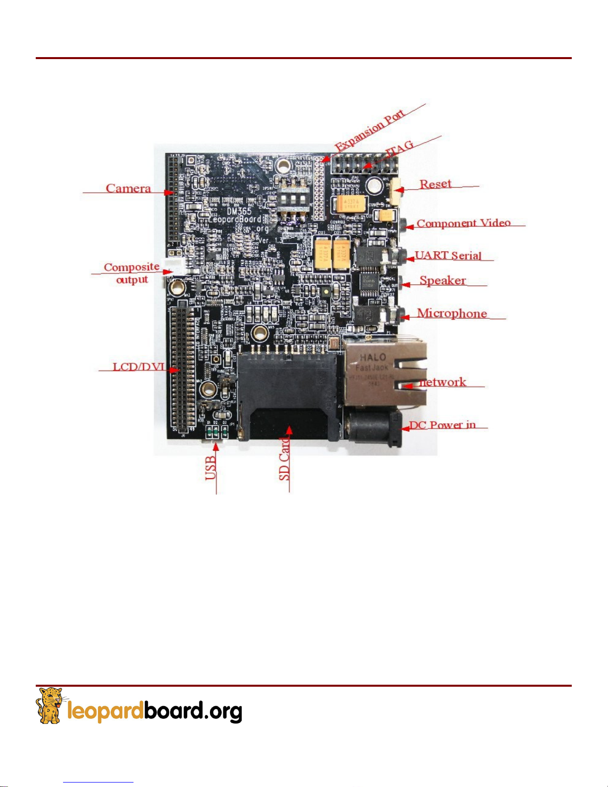
Leopardboard
365
Hardware Guide
Rev. 1.0
Page 26
2.2
Leopardboard
Figure
365
Function Block,
22.
Leopardboard
see
Figure
365
Function Blo
22
ck
The following sections provide more detail on each feature and components on the Leopardboard 365.
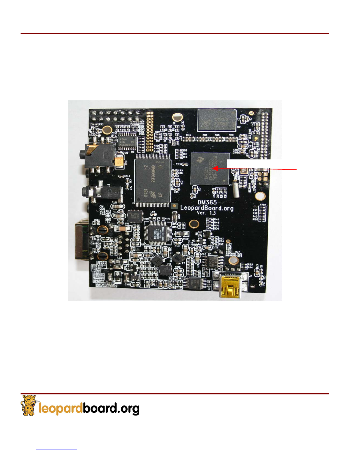
2.3 DM365 Processor
The Leopardboard 365 takes TMS320DM365 as its main processor. The DM365 is a highly integrated,
programmable platform for digital still camera, digital photo frames, IP security cameras, video door bell
application, etc. This ARM9-based DM365 device supports production-qualified H.264, MPEG-4, MPEG-2,
MJPEG and VC1/WMV9 codecs providing customers with the flexibility to select the right video codec for
their application. The DM365 also enables seamless interface to most addition al external devices required for a
complete digital camera implementation. The image sensor interface is flexible enough to support CCD,
CMOS, and various other interfaces such as BT.565, BT1120. The DM365 also offers a high level of
Page 27
Leopardboard
365
Hardware Guide
Rev. 1.0
Page 27
integration with HD display support including, 3 built-in 10-bit HD Analog Video Digital to Analog Converters
(DACs), DDR2/mDDR, Ethernet MAC, USB 2.0, integrated audio, Host Port Interface (HPI), Analog to Digital
Converter, and many more features saving developers on overall system costs as well as real estate on their
circuit boards allowing for a slimmer, sleeker design. The DM365 processor core is an ARM926EJ-S RISC
processor offering speeds up to 300MHz. The ARM926EJ-S is a 32-bit processor core that performs 32-bit and
16-bit instructions and processes 32-bit, 16-bit, and 8-bit data. The core uses pipelining so that all parts of the
processor and memory system can operate continuously. See Figure 23
Figure
23. DM355 Processor
DM365 Processor
Page 28
Leopardboard
365
Hardware Guide
Rev. 1.0
Page 28
2.4
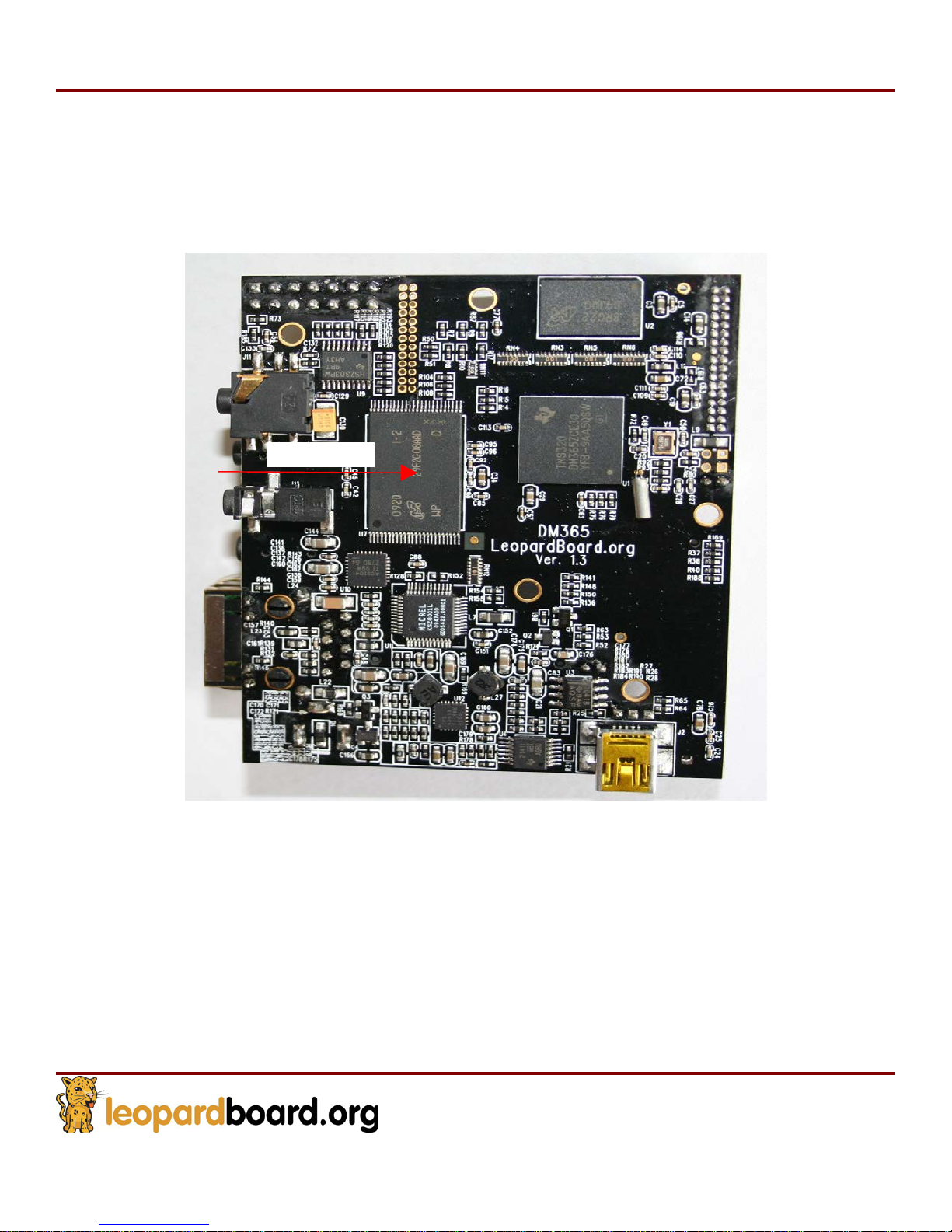
Flash Memory
The Micron Flash Memory is used in Leopardboard 365, it is a +3.3V powered, 256M x 8bit, 2Gb SLC NAND Flash. It is compatible with 1Gb NAND Flash, see Figure 24.
Nand Flash
Figure
24. NAND
Flash
Page 29
Leopardboard
365
Hardware Guide
Rev. 1.0
Page 29
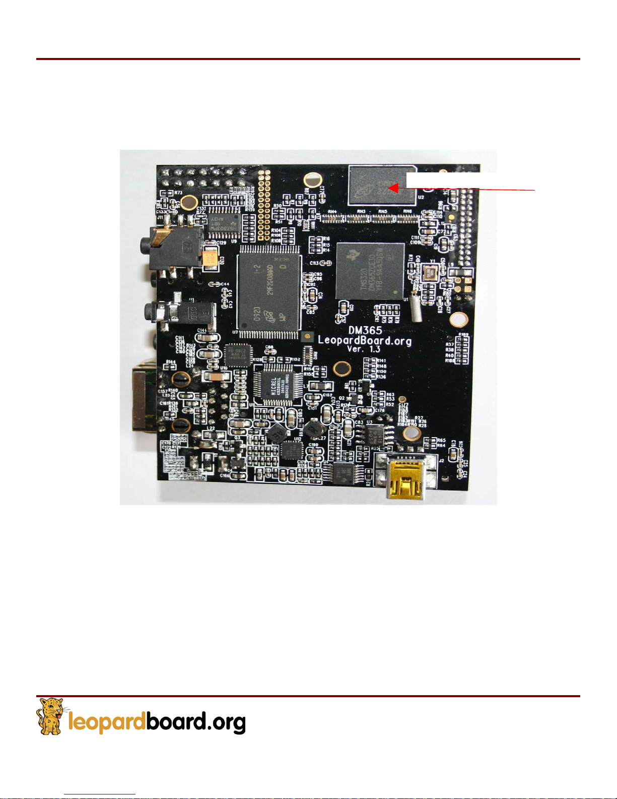
2.5 DDR2 SDRAM
The Micron DDR2 SDRAM is used in Leopardboard 365, it is a +3.3V powered, 8M x 16 x
8 banks, 1Gb DDR2 SDRAM, see Figure 25
Figure
25. DDR2 SDRAM
DDR2 SDRA
M
Page 30
Leopardboard
365
Hardware Guide
Rev. 1.0
Page 30
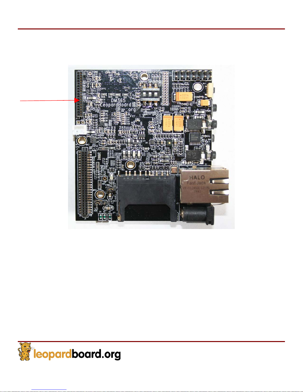
2.6 Camera Interface
Leopardboard 365 supports wide range of CMOS Imagers from VGA, 1.3M, 2M, 3M to 5
Mega-pixel CMOS sensors, see Figure 26.
Camera Interface
Figure
26. Camera Interface
Page 31
Leopardboard
365
Hardware Guide
Rev. 1.0
Page 31
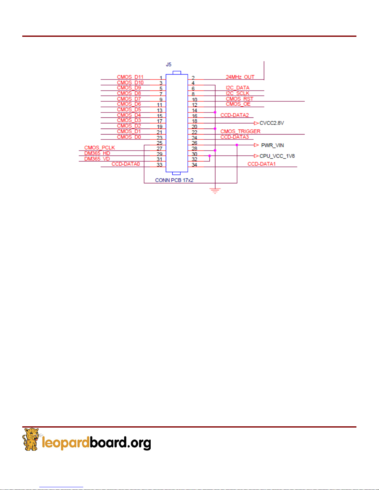
Camera interface Pin assignment, see Figure 27.
Figure
27. Camera
a
ssignment
Interface Pin
Page 32
Leopardboard
365
Hardware Guide
Rev. 1.0
Page 32
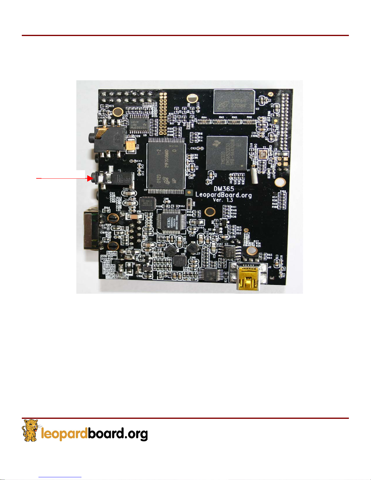
2.7 Audio Input
Low power stereo audio CODEC TLV320AIC3104 is used in Leopardboard 365; a 2.5mm
standard stereo audio input jack is provided to receive stereo audio input to CODEC, see
Figure 28.
Microphon
Figure
28. Audio Input
e
Page 33
Leopardboard
365
Hardware Guide
Rev. 1.0
Page 33
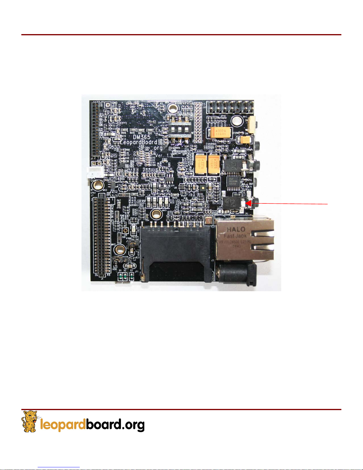
2.8 Audio Output
A 2.5mm standard stereo audio output jack is provided to access the stereo output of
the onboard output CODEC, see Figure 29.
Audio output
Figure
29. Audio Output
Page 34
Leopardboard
365
Hardware Guide
Rev. 1.0
Page 34
2.9
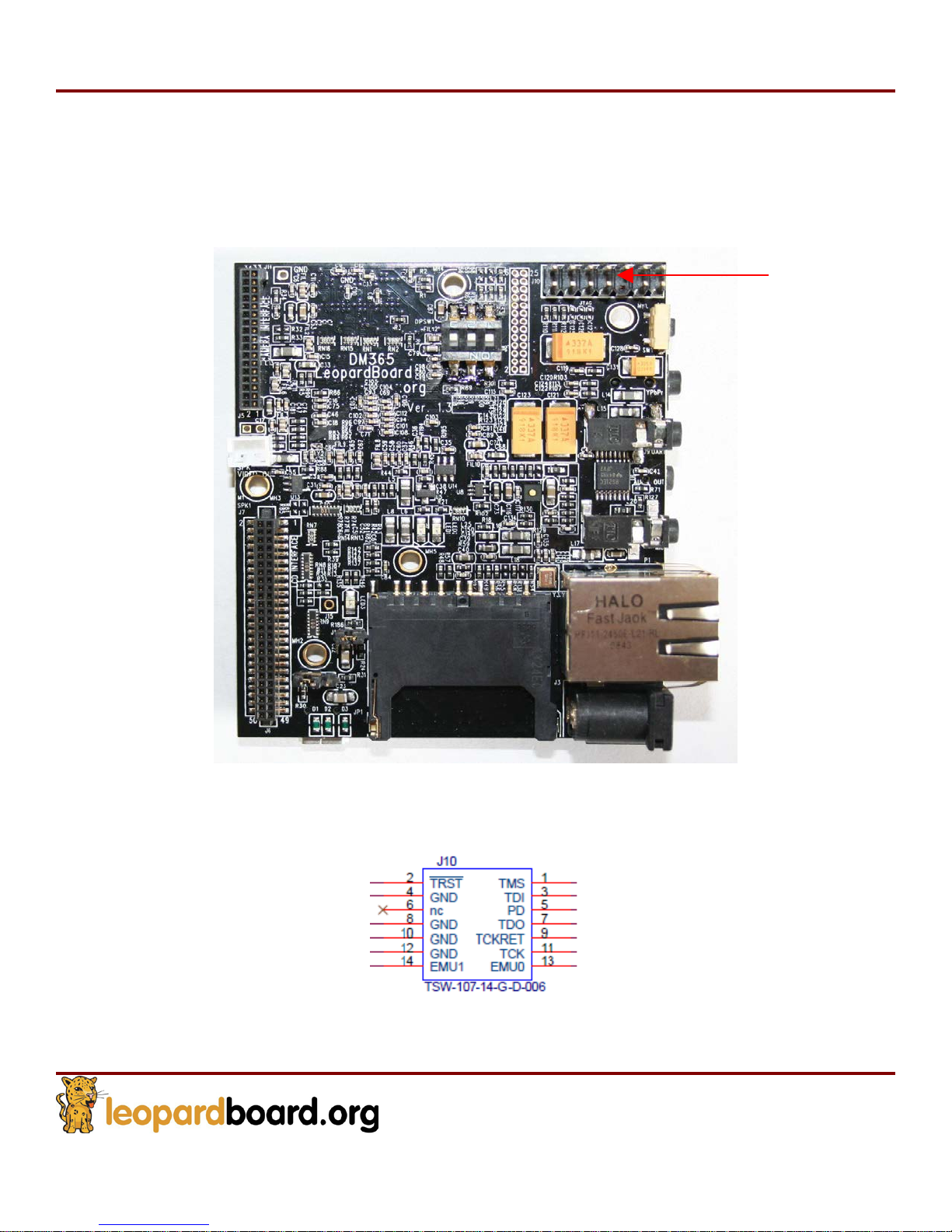
JTAG Port
A 14 pin JTAG header is provided on the Leopardboard 365 to facilitate the SW
development and debugging of the board by using various JTAG emulators, see Figure
30.
Figure
30.
JTAG Connecto
JTAG connector pin assignment, see Figure 31.
r
JTAG
Figure
31. 14-pin
TI JTAG Interface
Page 35
Leopardboard
365
Hardware Guide
Rev. 1.0
Page 35
2.10
Serial Port: RS-232
Support for RS232 is provided by a 2.5mm stereo audio jack on the Leopardboard 365
for access to an onboard RS232 transceiver. It does require a 2.5mm stereo audio jack to
DB9 Female converter cable, which is an accessory part, to access the serial port, see
Figure 32.
Figure
32. UART
Serial Port
Serial Port
Page 36
Leopardboard
365
Hardware Guide
Rev. 1.0
Page 36
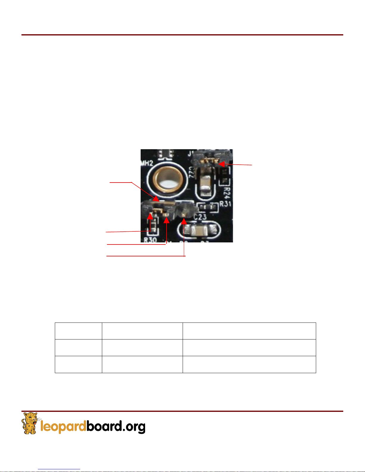
2.11 USB 2.0 Port and USB Host Mode
Leopardboard v1.3 supports USB device mode and host mode. (By default, the hardware is set to device mode)
To change between these two modes, J1 and J4 needs to be adjusted accordingly. For these two jumpers, J1 has
2 pins and J4 has 3 pins. Please see Figure 33 for pin assignment of J4.
For device mode, no jumper should be placed on J1 while the jumper on J4 should stay on Pin 1 & Pin 2. For
host mode, jumper should be placed on J1 while the jumper on J4 should stay on Pin 2 & Pin 3.
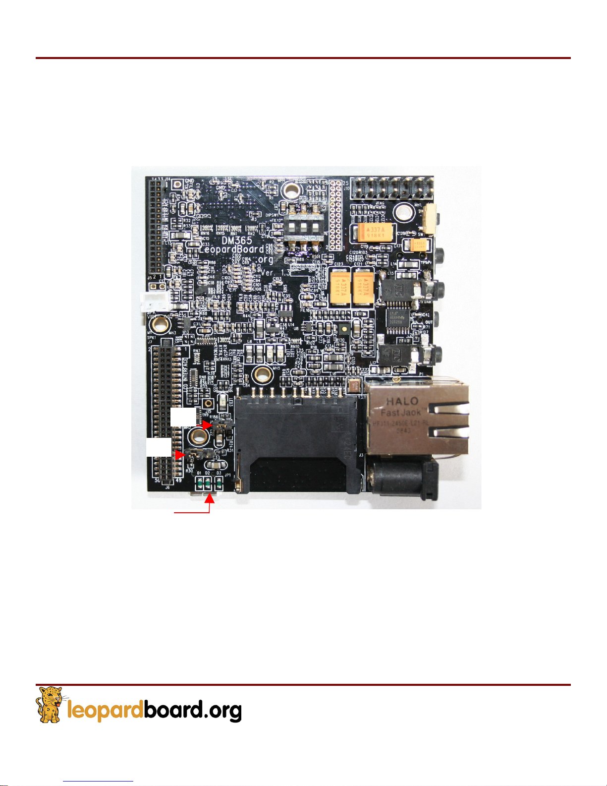
Please see Figure 34 for the position of J1, J4 and the USB port.
J1
J4
Pin 1
Pin 2
Pin 3
Figure
Table 2 Jumper settings related to host & device mode
Mode J1 Setting J4 Setting
Device Mode No Jumper Jumper on Pin1 & Pin 2
Host Mode J
umpe
33 Pin assignment
of J4
r Jumper on Pin 2 & Pin 3
Page 37
Leopardboard
365
Hardware Guide
Rev. 1.0
Page 37
The Leopardboard 365 requires a mini-B to USB type-A cable. Leopardboard 365 can be accessed
through USB cable, there is an option to provide +5V power to the Leopardboard 365 if external
+5V power supply is not used.
J4
J1
USB
Figure
Figure
34 USB 2 0 Port & 1 4
. .
34. USB port and
J1 J4
J J
Page 38
Leopardboard
365
Hardware Guide
Rev. 1.0
Page 38
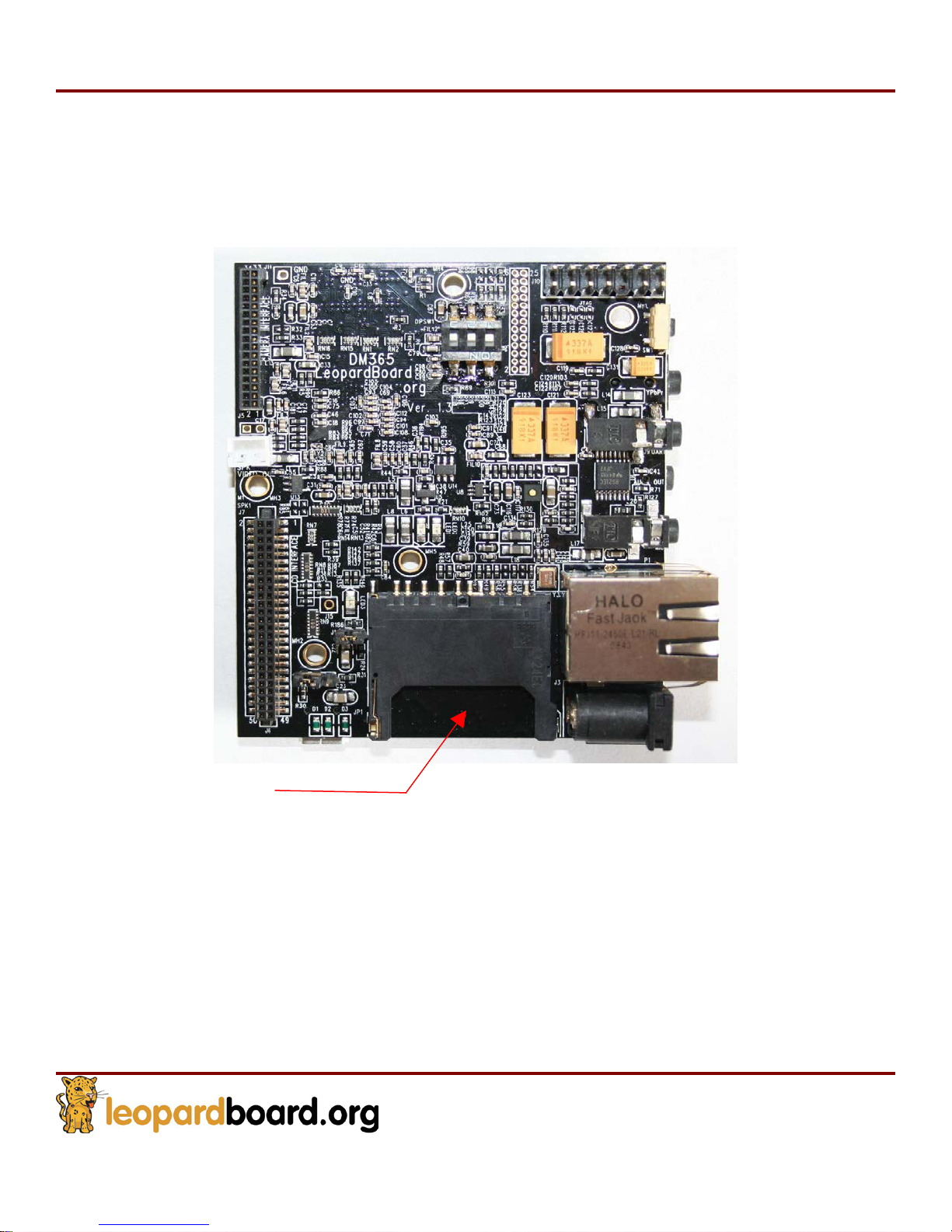
2.12 SD Card Slot
A SD Card connector is provided as a means for expansion and can support such
devices, but not limited as SD memory card, miniSD card, GPS modules, WiFi card, and
Bluetooth card, see Figure 35.
SD Card
Figure
35. SD Card
Page 39
Leopardboard
365
Hardware Guide
Rev. 1.0
Page 39
2.13
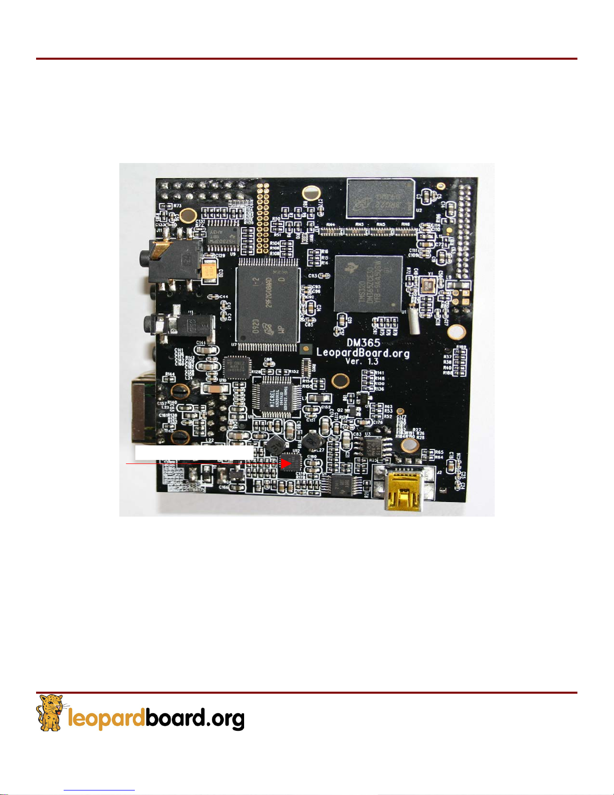
Power Management
A powerful 5-Channel Power Management IC with two step down converters and 3 low-
input voltage LDOs chip TPS65053 is provided in Leopardboard 365. It serves all powers
on the board, see Figure 36.
Power Management
Figure
36.
Power Management
Page 40
Leopardboard
365
Hardware Guide
Rev. 1.0
Page 40
2.14
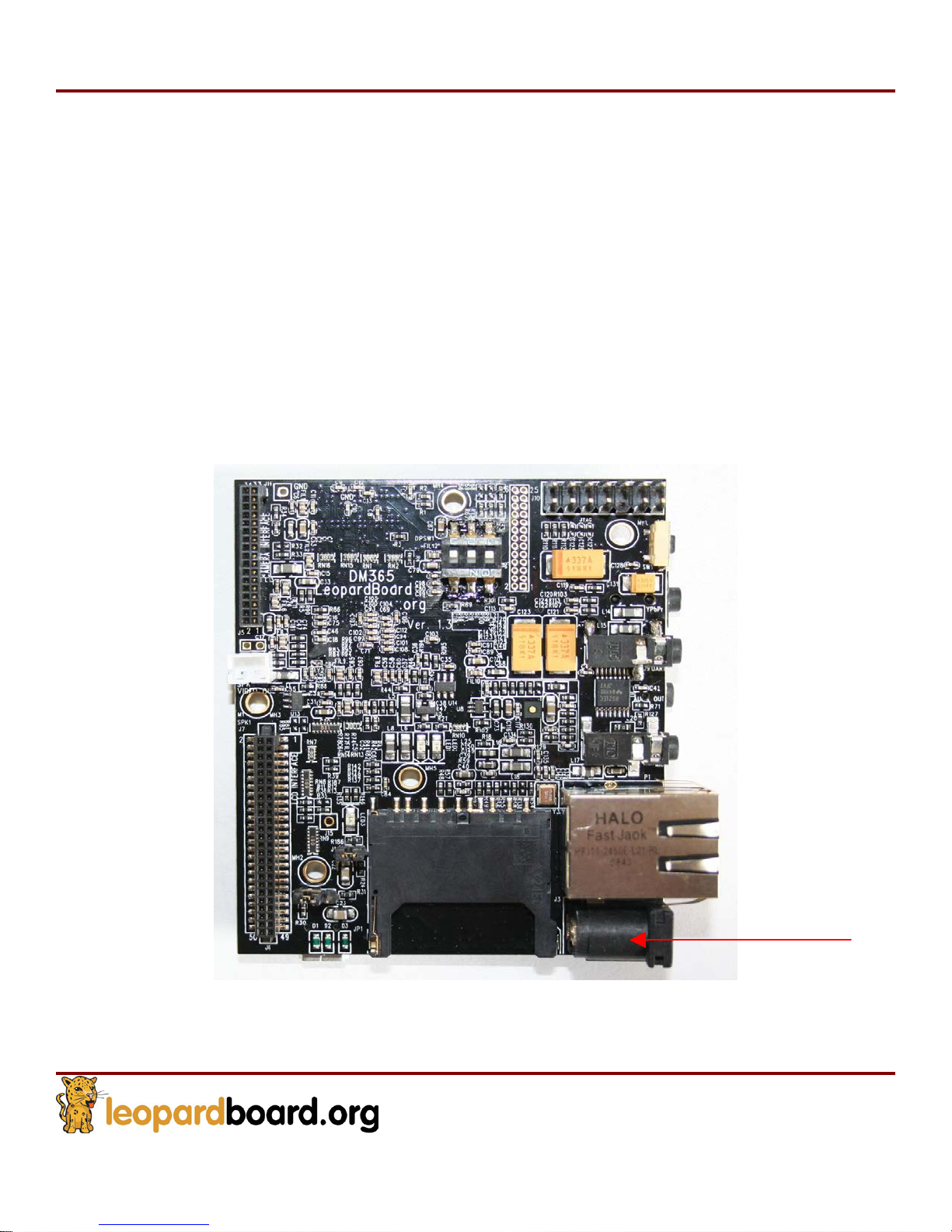
Power Input
A 2.1mm standard power jack is provided in Leopardboard 365 for +5VDC power supply,
the Leopardboard 365 power consumption is less than 2W, which includes 5M camera
board power consumption running at 720p @ 30fps.
A standard 2.1mm jack wall supply is needed, which is an accessory part, power can also
be supplied via the USB connector as an alternative supply,
When external power supply is provided, it will remove the power path from the USB
connector.
DO NOT plug in
possibly damaged although
Figure 37.
anything
but 5V to the
the board has over
Figure
37. DC Input
power
jack, or the board will be
voltage protection function,
DC Power IN
see
Page 41
Leopardboard
365
Hardware Guide
Rev. 1.0
Page 41
2.15
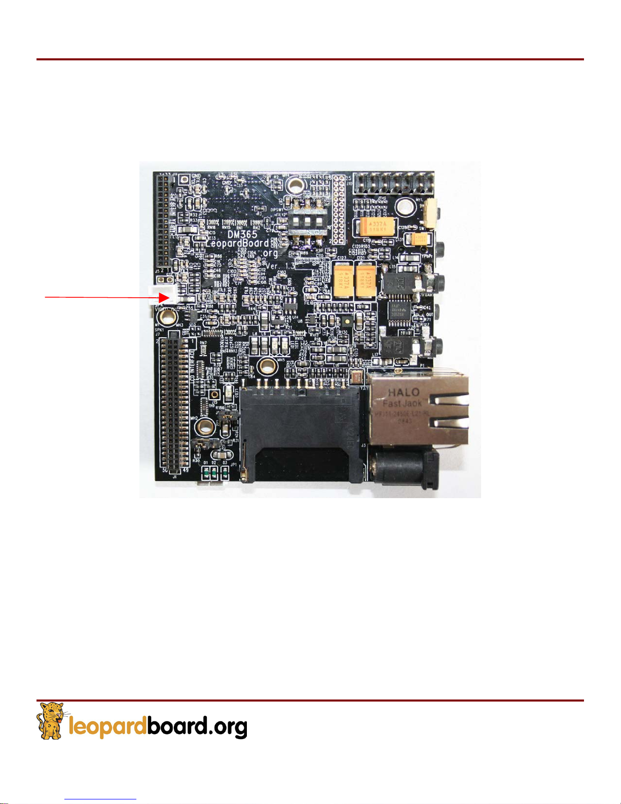
Composite
Video
Output Port
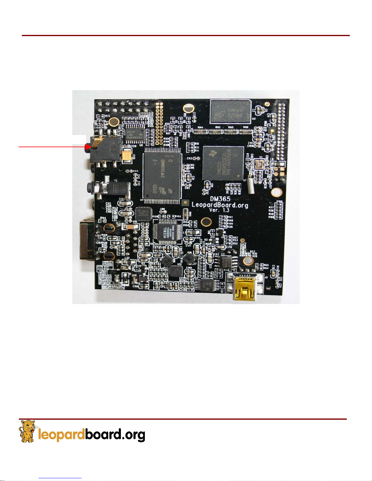
A two video pins is provided to access composite video output of Leopardboard 365. It
supports NTSC or PAL format output to a standard TV. The default is NTSC, but can be
switched to PAL by software, see Figure 38.
Composite Output
Figure
38.
Composite Output
Page 42
Leopardboard
365
Hardware Guide
Rev. 1.0
Page 42
2.16
Component
Video Output
Leopardboard 365 has provided a jack to access component video output supporting
YPbPr format to output to a TV or other component. See Figure 39.
Component Output
Figure
39.
Component
Video Output
Page 43
Leopardboard
365
Hardware Guide
Rev. 1.0
Page 43
2.17
Network Interface
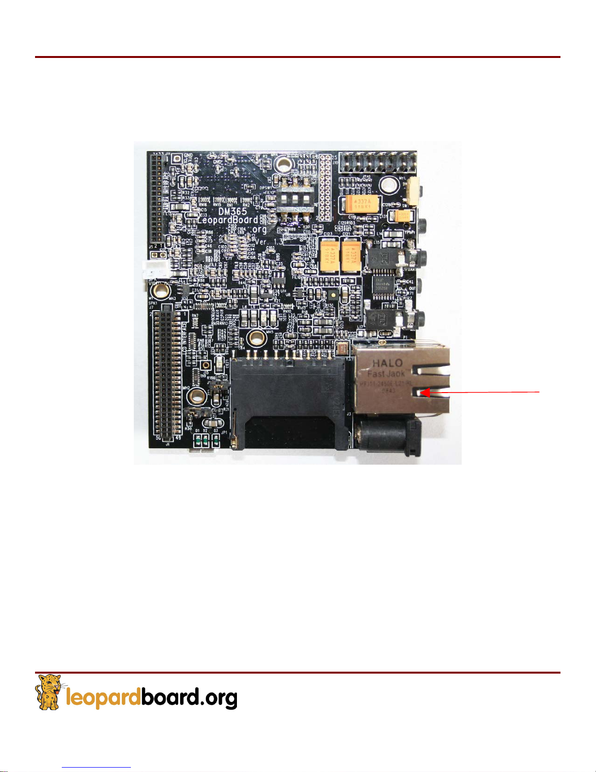
Network is provided in Leopardboard 365, this is a standard RJ-45 connector for 10/100
Mbps Ethernet networks, see Figure 40.
Figure
40.
Network Interface
Network
Page 44
Leopardboard
365
Hardware Guide
Rev. 1.0
Page 44
2.18
LCD/DVI Interface
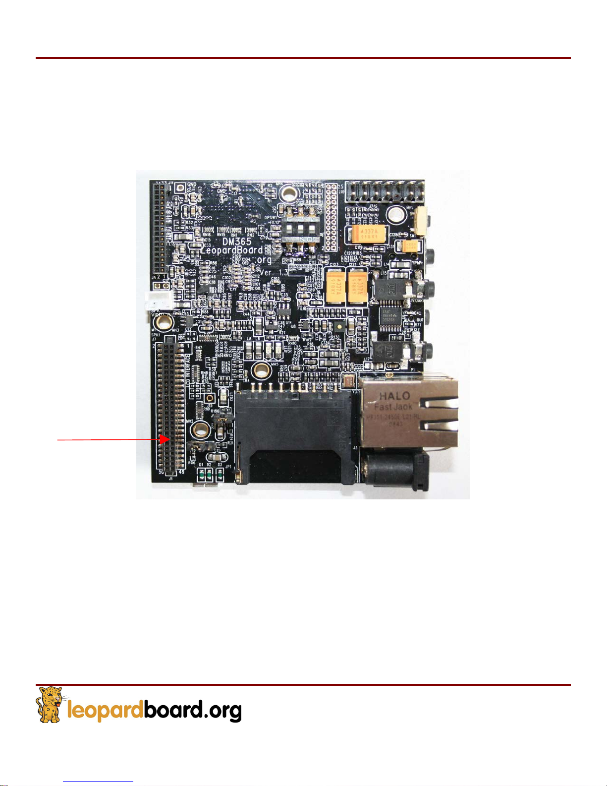
Leopardboard 365 provides a 50-pin connector, which is fully compatible with
DM365EVM expansion connector; it supports LCD daughter card or DVI daughter card,
see Figure 41.
LCD/DVI Interface
Figure
41.
LCD/DVI Interface
Page 45
Leopardboard
365
Hardware Guide
Rev. 1.0
Page 45
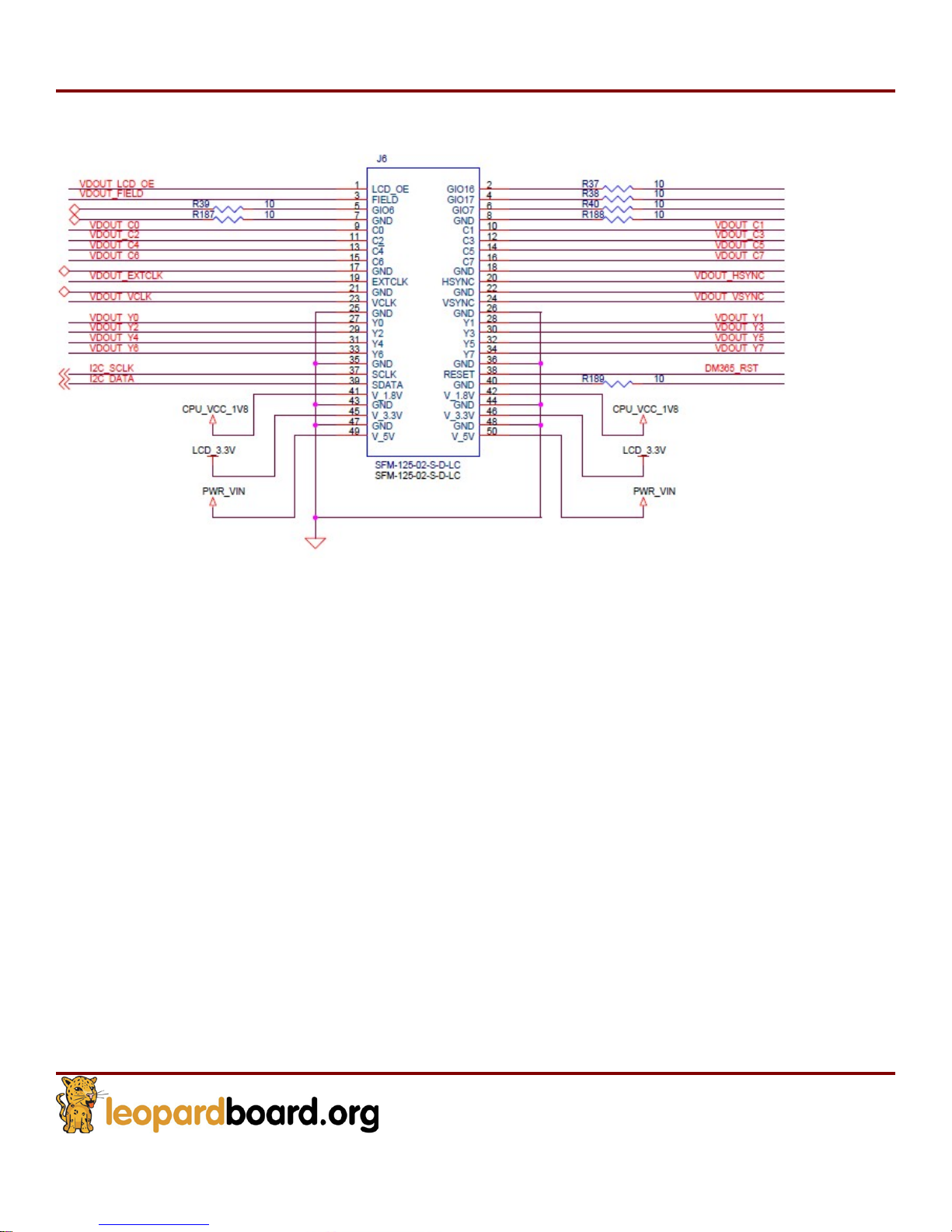
LCD interface pin assignment, see Figure 42
Figure
42. Pin
LCD Interface
Assignment for
Page 46
Leopardboard
365
Hardware Guide
Rev. 1.0
Page 46
2.19
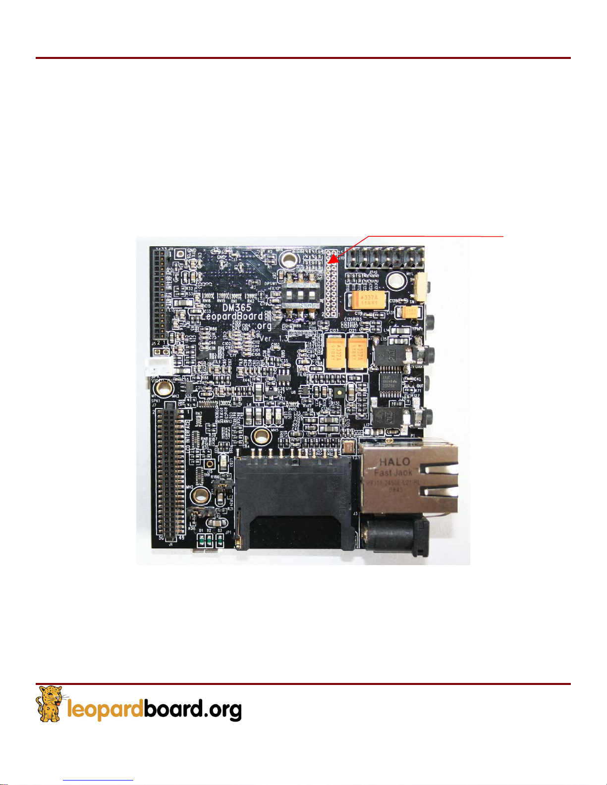
Expansion Port
A 26-pin connector is provided as expansion port to support the following functions, see
Figure 43.
SD/MMC
I
2C
UART
McBSP
GPIO
3.3V power supply.
Figure
43.
Expansion Interface
Expansion Port
Page 47
Leopardboard
365
Hardware Guide
Rev. 1.0
Page 47
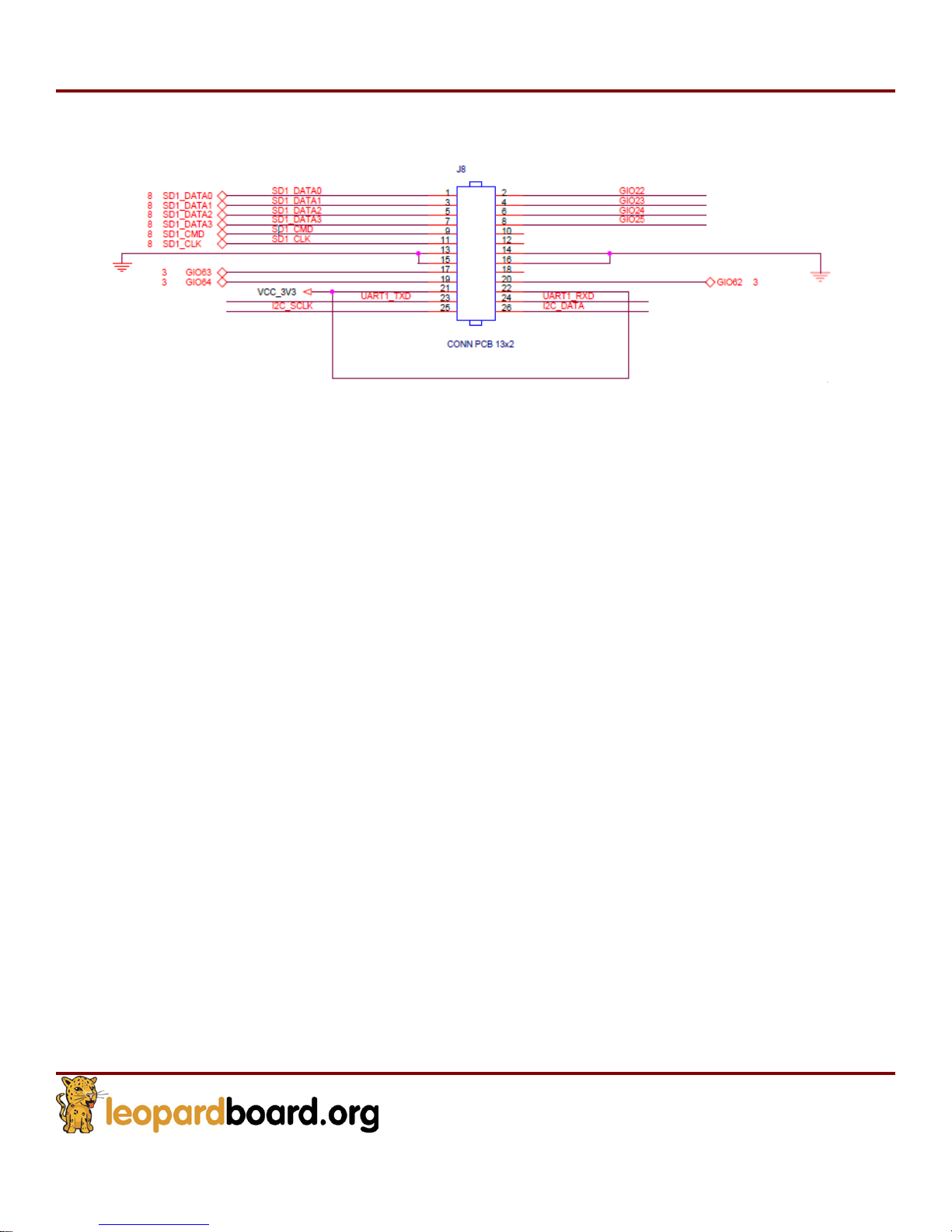
Expansion port pin assignment, see Figure 44.
Figure
44. Pin
Expansion port
Assignment for
Page 48
Leopardboard
365
Hardware Guide
Rev. 1.0
Page 48
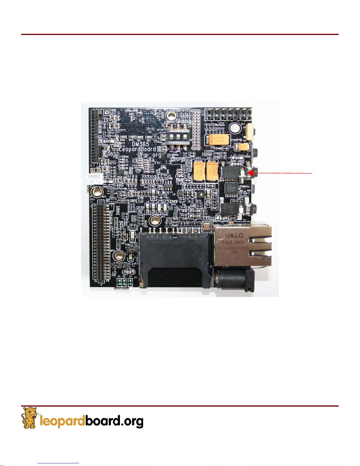
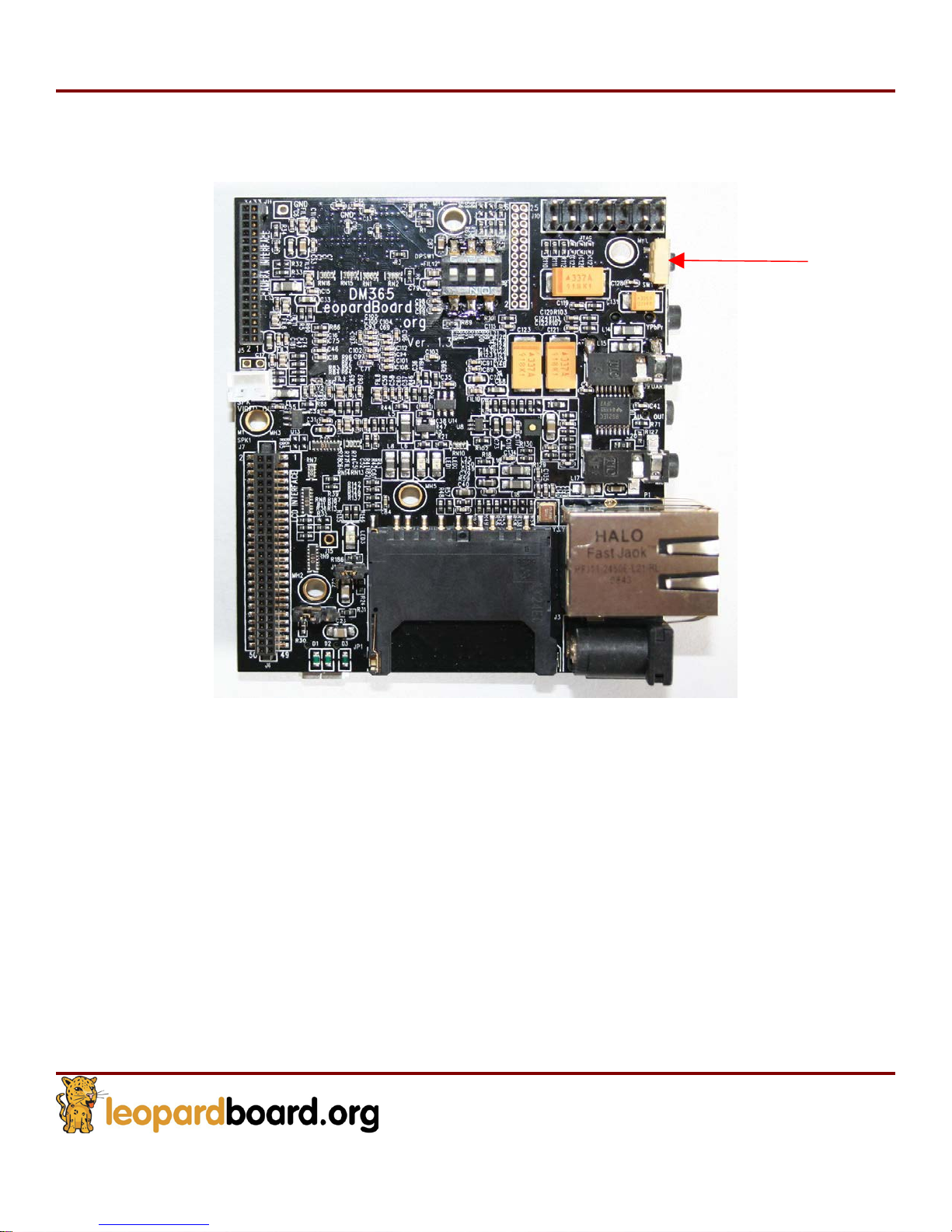
2.20 Reset Button
Reset button can reset board to power-up status. See Figure 45
Figure
45. Reset Button
et
Res
Page 49
Leopardboard
365
Hardware Guide
Rev. 1.0
Page 49
EM
_A13,
#
1
EM_A12, #2
EM_A11, #3
BOOT MODE
0 0 0
Nand Boot Mode
0 1 0
SD Boot Mode
0 1 1
UART Boot Mode
1 0 0
USB Boot Mode
1 1 0
EMAC Boot Mode
2.21
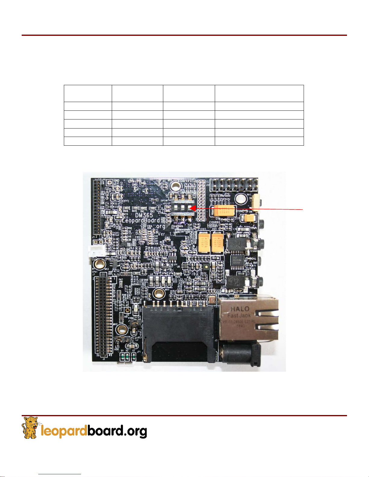
DIP Switch
Leopardboard 365 has included a DIP switch for boot up control. See table 3 for boot
control modes.
(“0”= off, “1”= on)
Figure
46
shows
the
DIP switch
Figure
on
Leopardboard 365
46.
DIP
Switch
Switch
Page 50

Leopardboard
365
Hardware Guide
Rev. 1.0
Page 50
PCB Board
Board Size: 3.0” x 2.5”
Max height: 0.67” with RJ45 Connector
Layers: 6
Color: Black
PCB thickness: .062”
RoHS Compliant: Yes
Weight: 1.5 Oz
Mechanical Spe
cif
ication
Page 51
Компания «ЭлектроПласт» предлагает заключение долгосрочных отношений при
поставках импортных электронных компонентов на взаимовыгодных условиях!
Наши преимущества:
Оперативные поставки широкого спектра электронных компонентов отечественного и
импортного производства напрямую от производителей и с крупнейших мировых
складов;
Поставка более 17-ти миллионов наименований электронных компонентов;
Поставка сложных, дефицитных, либо снятых с производства позиций;
Оперативные сроки поставки под заказ (от 5 рабочих дней);
Экспресс доставка в любую точку России;
Техническая поддержка проекта, помощь в подборе аналогов, поставка прототипов;
Система менеджмента качества сертифицирована по Международному стандарту ISO
9001;
Лицензия ФСБ на осуществление работ с использованием сведений, составляющих
государственную тайну;
Поставка специализированных компонентов (Xilinx, Altera, Analog Devices, Intersil,
Interpoint, Microsemi, Aeroflex, Peregrine, Syfer, Eurofarad, Texas Instrument, Miteq,
Cobham, E2V, MA-COM, Hittite, Mini-Circuits,General Dynamics и др.);
Помимо этого, одним из направлений компании «ЭлектроПласт» является направление
«Источники питания». Мы предлагаем Вам помощь Конструкторского отдела:
Подбор оптимального решения, техническое обоснование при выборе компонента;
Подбор аналогов;
Консультации по применению компонента;
Поставка образцов и прототипов;
Техническая поддержка проекта;
Защита от снятия компонента с производства.
Как с нами связаться
Телефон: 8 (812) 309 58 32 (многоканальный)
Факс: 8 (812) 320-02-42
Электронная почта: [email protected]
Адрес: 198099, г. Санкт-Петербург, ул. Калинина,
дом 2, корпус 4, литера А.
 Loading...