

Page 1

PCinterface
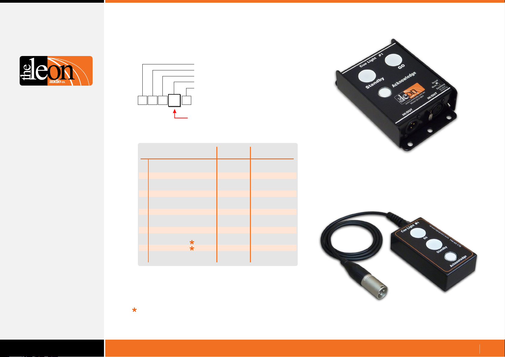
16 channel Cue Light control from
your Touch Screen or Show Control PC
Control up to 6 Cue Light Master Stations
•
Control 240 Outstations across 96 channels
•
Simple 5 byte ASCII commands
•
Return Status Monitoring
•
Supports RS232 and 4 wire RS485
•
QL-PCi mk4
www.LeonAudio.com.au
01.
Page 2
Quick Start Guide
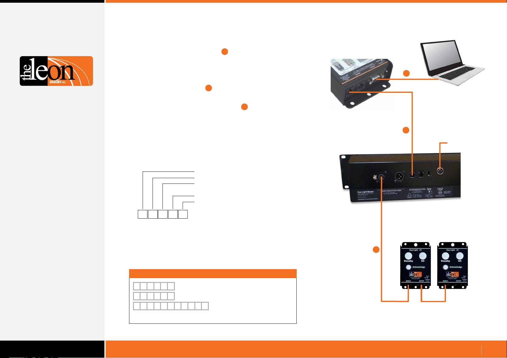
Connect the Show Control computer to the
•
PCinterface using an RS232 cable.
A USB to RS232 adaptor (not supplied) will be required if the Show
Control computer lacks an RS232 port.
Connect the PCinterface’s 6 pin RJ12 Expansion port to either of
•
the two RJ12 Expansion ports on the Master Station using the
supplied RJ12 - RJ12 cable.
Connect one or more Cue Light Outstations to either of the
•
two XLR connectors on the Master Station.
Set the Show Control Computer’s serial port to 9600 baud, N81,
•
no handshaking. Baud rate can be changed from 2,400 to 115,200
once the initial connection has been established.
The QL-PCi will now be sending the Heart Beat signal to the Show
•
Control computer. This is a 5 byte ASCII string {RRH1
Basic Control Commands are 5 ASCII bytes.
•
[
1
G 15
2
Command Header: Left square bracket
Master’s Address 1-6
Channel number 1-16
(Letters A-G are used for ch 10-16)
Function: G = Go S = Standby
Value: 1 = trigger 0 = clear
Control Command Format.
RS232 port on the
1
3
1
Show Control
computer
PCinterface
QL-PCi Mk4
2
Power
Master Station’s rear panel
Each 5 byte command is held in a buffer in the PCinterface and is
not executed until the single letter X for eXecute is received.
Multiple commands may be entered followed by a single X.
Letters are not case sensitive. Spaces are only permitted between
each 5 byte command and/or the letter X.
Examples
[
1 5
[
1 5
[
1 2
X
S
1
G
1
S
0
Master 1, Ch 5, S/by Cue, Trigger, eXecute.
X
Master 1, Ch 5, Go Cue, Trigger, eXecute.
[
1 3
X
G
1
Master 1, Ch 2, S/by Cue, Clear,
Master 1, Ch 3, Go Cue, Trigger,
and eXecute.
3
Cue Light Outstations
www.LeonAudio.com.au
02.
Page 3

Index
2
Quick start Guide
5
PCinterface Overview
6
Command Format Overview
7
Simple GUI Command Format
8
Programming Simple GUI Commands
9
10
11
12
13
14
15
16
17
18
19
20
21
22
23
Button number allocation
Expanded button number allocation
Table of button numbers
Startup in Simple GUI mode
Cue Sheet Commands
Programming Cue Sheet Commands
Channel Number
Additional options for the channel number
Functions and Values
Go Cue
Standby Cue
Clear any Cues
Sound the Beeper
Channel’s Group Button
Miscellaneous Commands
Reset Flashing Fault Lamps
Table of Cue Sheet Commands
Return Monitoring
Simple GUI Reply
Channel & Function Reply
Request Lamp Status
Monitoring Reply Mode command
Termination Character
Reply Pacing
Simple GUI Reply format.
Lamp Numbers
Table of Lamp Numbers
26
Configuration Commands
Configuration Command Format
Configuration Command Header
Master Station Address
27
28
29
30
31
32
33
34
35
36
37
38
39
40
41
42
43
44
45
46
47
Channel number
Additional options for the channel number
Overview of Functions
Cue Light Outstation Functions
Table of Cue Light Outstation Configuration Commands
Outstation’s Standby Colour
Standby Lamp Flash on Master
S/by Lamp Flash on Outstation
S/by latches
Standby Dims on Acknowledge
Outstation Go Flickers
Go times out
Go Flashes after 3 seconds
Go latches
Go & S/by interlocked
Call lamp enabled
Call lamp flashes
Acknowledge button back-light
Beeper enable
Beep-on-Go
Change colour on Acknowledge
Dimmer
Relay Outstation Functions
Table of Cue Light Outstation Configuration Commands
Mode
S/by Lamp Flash on Master
S/by Lamp Flash on Outstation
S/by latches
Go times out
Go Flashes after 3 seconds
Go latches
Go & S/by interlocked
Call lamp enabled
Call lamp Flashes
All Lamps on Outstation
Table of Return Monitoring.
24
25
Channel & Function format
Other Return Monitoring
Master’s on-line status
Heart Beat signal
Heart Beat on/off command
Sensor Outstation Functions
48
49
50
51
Table of Sensor Outstation Configuration Commands
Unsafe Lamp
Safe when... open/closed
End Of Line Resistors
All Lamps on Outstation
www.LeonAudio.com.au
03.
Page 4

Index
Configuration Commands. Cont.
Master Station Functions
52
53
54
57
58
59
60
61
62
63
64
65
66
67
68
69
71
72
Table of Master Station Configuration Commands
Copy 1 of 8 files to PC
Copy 1 of 7 files to the ShowTime file
Copy ShowTime file to Installer's Default or 1 of 4 User files
Go Cue Total Duration (1 to 16 seconds)
Link the 4 Group Master buttons between multiple Masters
PCinterface Functions
Table of PCinterface Configuration Commands
Monitoring Reply Mode command
Baud Rate
Heart Beat
Reply Pacing. Pause between each 5 byte reply
Terminator character
Testing
Testing the PCinterface to PC serial link
PCinterface Loop-back Test
A 10 second test
What if it doesn’t work?
Connections
Summary of Commands
Programming Simple GUI Commands
Table of button numbers
Table of Cue Sheet Commands
Summary of Configuration Commands
73
Overview of Functions
Table of Cue Light Outstation Configuration Commands
74
Table of Relay Outstation Configuration Commands
75
Table of Sensor Outstation Configuration Commands
76
Table of Master Station Configuration Commands
77
Table of PCinterface Configuration Commands
78
Return Monitoring. Simple GUI Reply format
79
80
81
82
Table of Lamp Numbers
Table of Return Monitoring.
Channel & Function format
ASCII table
Specifications
Warranty
www.LeonAudio.com.au
04.
Page 5
PCinterface Overview
Control your Cue Light system from a PC or Show Controller
•
PC, Mac or show controller
Will work with any PC, Mac or hardware controller capable of
sending ASCII characters via a RS232 or RS485 serial port.
Trigger or cancel cues, configure Outstation features and more.
•
Cue Light Outstations and Masters
A single PCinterface can control from 1 to 6 Master Stations.
Each 16 channel Master can control up to 40 Outstations giving a
maximum of 240 Outstations across 96 channels.
Buttons on the Master Station(s) remain operational while the
PCinterface is connected allowing for manual ad hoc cues.
Each Master requires its own wiring universe for its associated
Outstations.
•
Command structure
All basic commands are 5 bytes long. Most commands can be
typed from a keyboard using only ASCII characters.
No Escape sequences or control characters are used.
Return monitoring is provided in a choice of 2 different formats.
Can be easily tested with any Terminal communications program.
Simple GUI mode
•
A simple command interface for use with touch screens.
Each button on the Master Station has been assigned a number,
and by using a single command, any button can be pressed or
released.
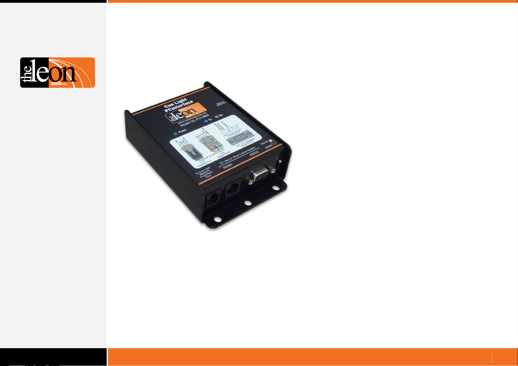
PCinterface
QL-PCi mk4
Cue Sheet Command Format
•
A command interface for use with a Show Control system using a
pre-loaded cue list.
•
Configuration Data
Allows the Master Station(s) and all 3 types of Outstation to be
remotely configured. e.g. Flashing/steady Go and Standby lamps,
Standby lamp colour. Almost 40 different parameters can be
changed. Configuration data can also be downloaded.
Return Monitoring
•
The status of every lamp on the Master Station(s) is returned to
the Show Controller in a choice of two data formats.
•
Supports RS232 and 4 wire RS485
2,400 to 115,200 baud.
It has a 500 byte FIFO buffer for incoming RS232/485 data.
www.LeonAudio.com.au
05.
Page 6
Command Format Overview
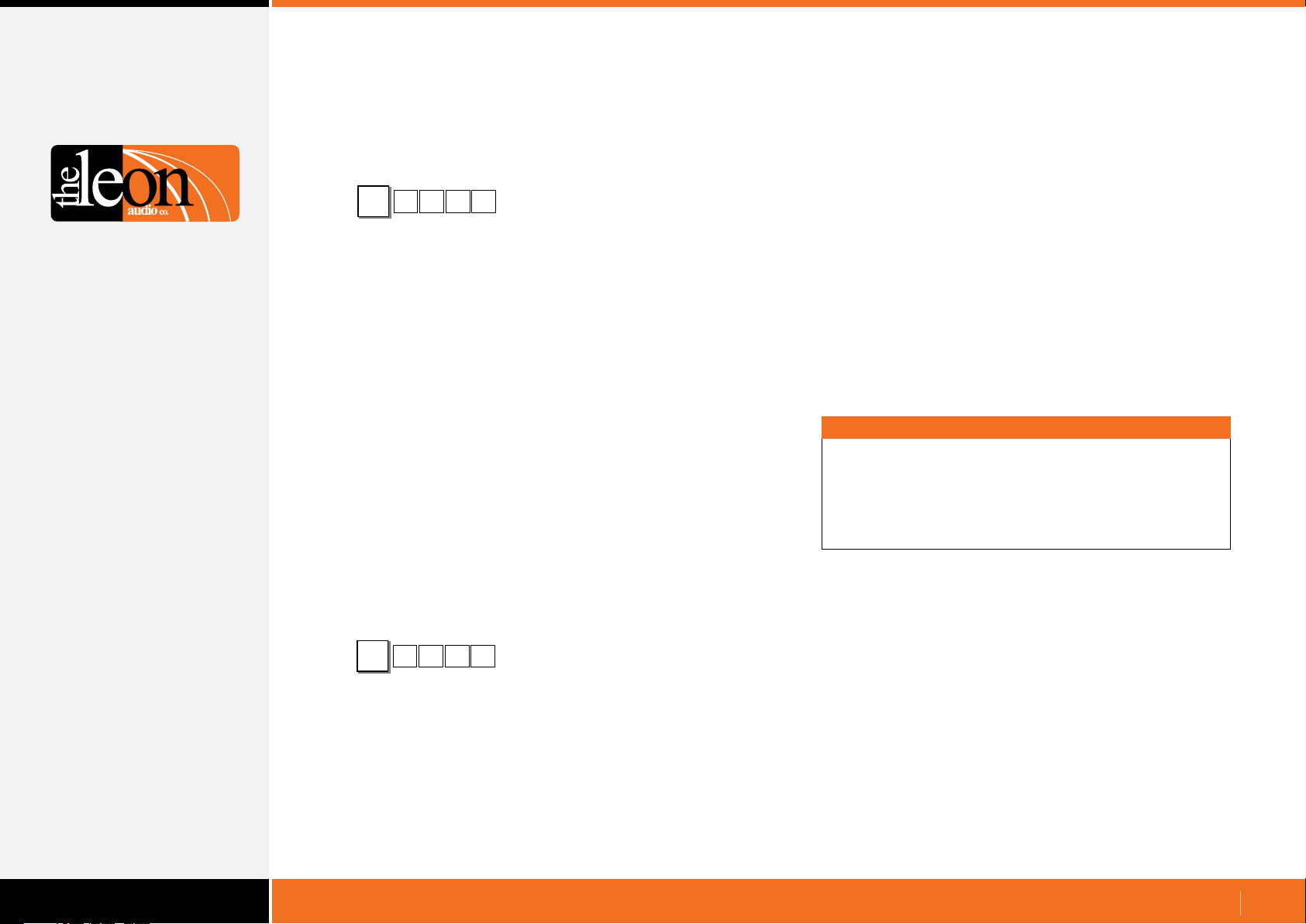
There are 3 classes of command available.
Simple GUI command format
•
Cue Sheet command format
•
1 G 13
[
These control Commands are used to control the Cue Light
System during a performance.
Simple GUI command format.
A simple command interface for touch screens.
The touchscreen sends a command to the PCinterface when any
touchscreen button is pressed or released. This toggles the
function of that key (in the same manner that the buttons on the
Master Station toggle on or off).
Cue Sheet command format.
For use with a show control system with a pre-loaded cue list.
The control system sends a command(s) to the PCinterface when
the Next cue button is pressed. It either triggers or clears a Go or
Standby command (if a cue is already triggered, it will remain
triggered i.e. it does not toggle as in Simple GUI).
Configuration command format
•
Operate Command Header
Note
The mechanical buttons on the Master Station(s) remain
100% operational while the PCinterface is connected.
This allows ad hoc cues to be given if needed.
It also allows cues to be given when your show control
system malfunctions.
1 A 38
{
Configuration Commands are usually used to configure the Cue
Light System prior to a performance.
Almost 40 different parameters can be changed in the Master
Station(s) for all 3 types of Outstation.
Configuration data can also be downloaded from the Master
Station via the PCinterface to the PC/Show Controller.
Configuration Command Header
www.LeonAudio.com.au
06.
Page 7
Simple GUI Command Format
A simple command interface for touch screens.
The touchscreen sends a command to the PCinterface when
any touchscreen button is pressed or released. This toggles the
function of that key (in the same manner that the buttons on the
Master Station toggle on or off).
Programming Simple GUI Commands
Programming is done via your touch screen control system.
(e.g. AMX or Medallion etc).
All characters are ASCII except for the button number (4th byte)
which is a decimal byte. Letters are not case sensitive.
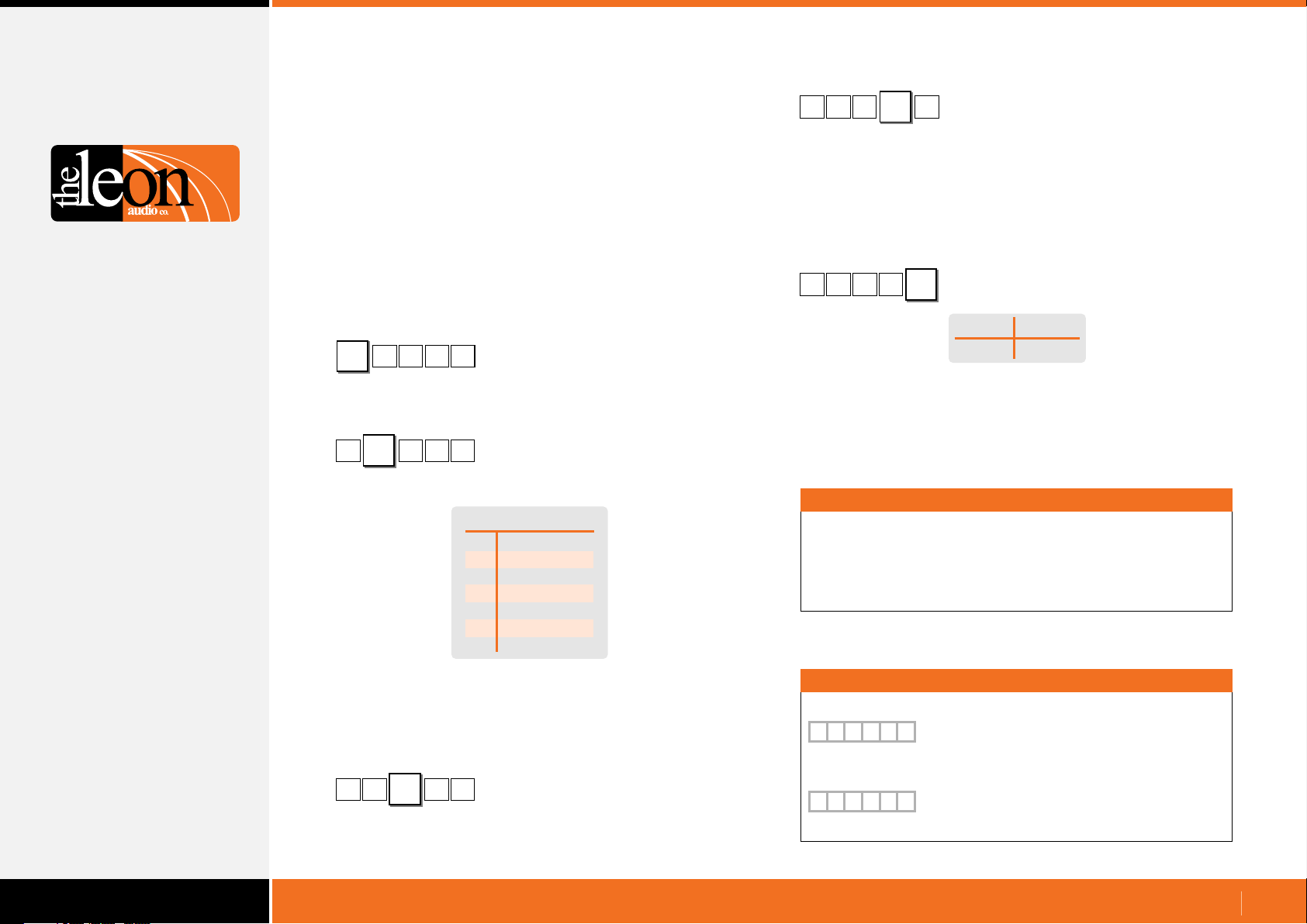
Operate Command Header
4 66
[
Header character to mark the start of a command.
[ 66 1N
4
Up to 6 Master Stations can be controlled by one PCinterface.
1N
Master Station Address (0-6)
Master’s Address
All Masters
0
Master #1
1
Master #2
2
Master #3
3
Master #4
4
Master #5
5
Master #6
6
[
4 N
This is a single byte decimal number (not ASCII) in the range
of 1 - 87.
It describes a specific button on the Master Station.
A single byte decimal number cannot be typed directly from a
PC’s keyboard. The buttons and their numbering scheme is
described on the following pages.
[
When the Pressed command is sent, it must always be followed
by a Released command - either immediately or after other
commands that are executed while that key is still pressed.
66
66N4
A specific button on the Master (1-87)
1
Pressed/Released command
1
Pressed
ASCII numbers
1
Released
0
Important
All commands must be followed by the letter X for eXecute.
Once X has been received by the PCinterface, the commands
are uploaded to the Master Station(s).
Multiple commands may be entered followed by a single X.
The Master Station’s address is set to 1 when shipped.
To change the address, please see Master Station options under
Configuration Editor in the PDF file 16 Channel Cue Light Mk4.
[
where a single Number is used to describe a specific button.
N
664
Letter N selects Simple GUI command
1
Examples
Button Pressed
[
4 N
66
X
1
Button Released
[
4 N
66
X
0
Master 4, N = Simple GUI command,
Button 66 (Ch1 Go), 1 = Pressed, eXecute.
Master 4, N = Simple GUI command,
Button 66 (Ch1 Go), 0 = Released, eXecute.
www.LeonAudio.com.au
07.
Page 8
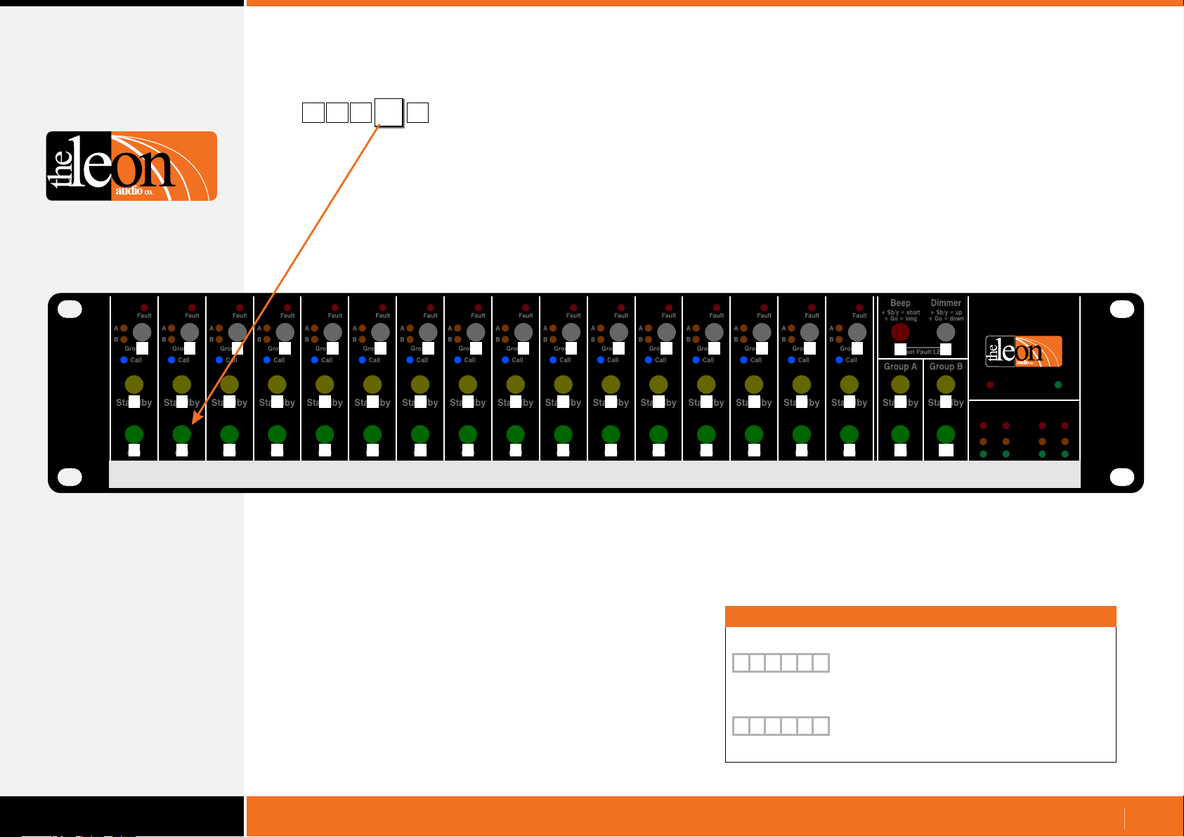
Programming Simple GUI Commands - button number allocation
[
67
A specific button on the Master Station.
1N4
This is a single byte decimal number in the range of 34 - 87.
It describes a specific button on the Master Station as illustrated
by the yellow numbers below.
Characters in the white boxes are their case sensitive ASCII
equivalents.
1 2 3 4 5 6 7 8 9 10 11 12 13 14 15 16
Fault
A
34 35 36 37 38 39
B
Group
“
Call
Fault
A
B
Group
#
Call
Fault
A
B
Group
$
Call
Fault
A
B
Group
%
Call
Fault
A
B
Group
&
Call
Fault
A
B
Group
‘
Call
Fault
A
40
B
Group
(
Call
Fault
A
41 42 43 44 45 46 47 48 49
B
Group
)
Call
Fault
A
B
Group
*
Call
Fault
A
B
Group
+
Call
Fault
A
B
Group
,
Call
Fault
A
B
Group
-
Call
Fault
A
B
Group
.
Call
Fault
A
B
Group
/ 0 1$
Call
Fault
A
B
Group
Call
50 51 52 53 54 55 56 57 58 59 60 61 62 63 64 65
Standby
Standby
2 3 4 5 6 7 8 9
Standby
Standby
Standby
Standby
Standby
Standby
Standby
:
;
Standby
66 67 68 69 70 71 72 73 74 75 76
B
GO
C
GO
D E F G H I J K L M N O P Q
GO
GO
GO
GO
GO
GO
GO
GO
Standby
Standby
< = > ?
GO
77
GO
Standby
78 79 80 81
GO
Standby
GO
@
Standby
GO
Fault
A
B
Group
Call
Standby
A
GO
Beep Dimmer
+ Sb/y = short
+ Go = long
+ Sb/y = up
+ Go = down
82 83
R S
Reset Fault LEDs
Group A Group B
84 85
Standby Standby
T
U
86 87
V W
GO GO
Cue Light
Master
QLM16 Mk4
www.LeonAudio.com.au
Short Power
Sensors
1 2 3 4
Fault
Unsafe
Safe
Each horizontal row of 16 buttons (channels 1-16) uses
consecutive numbers. Number 33 is not used as it is reserved.
Examples
Button Pressed
[
4 N
67
X
1
Button Released
[
4 N
67
X
0
Master 4, N = Simple GUI command,
Button 67 (Ch2 Go), 1 = Pressed, eXecute.
Master 4, N = Simple GUI command,
Button 67 (Ch2 Go), 0 = Released, eXecute.
www.LeonAudio.com.au
08.
Page 9
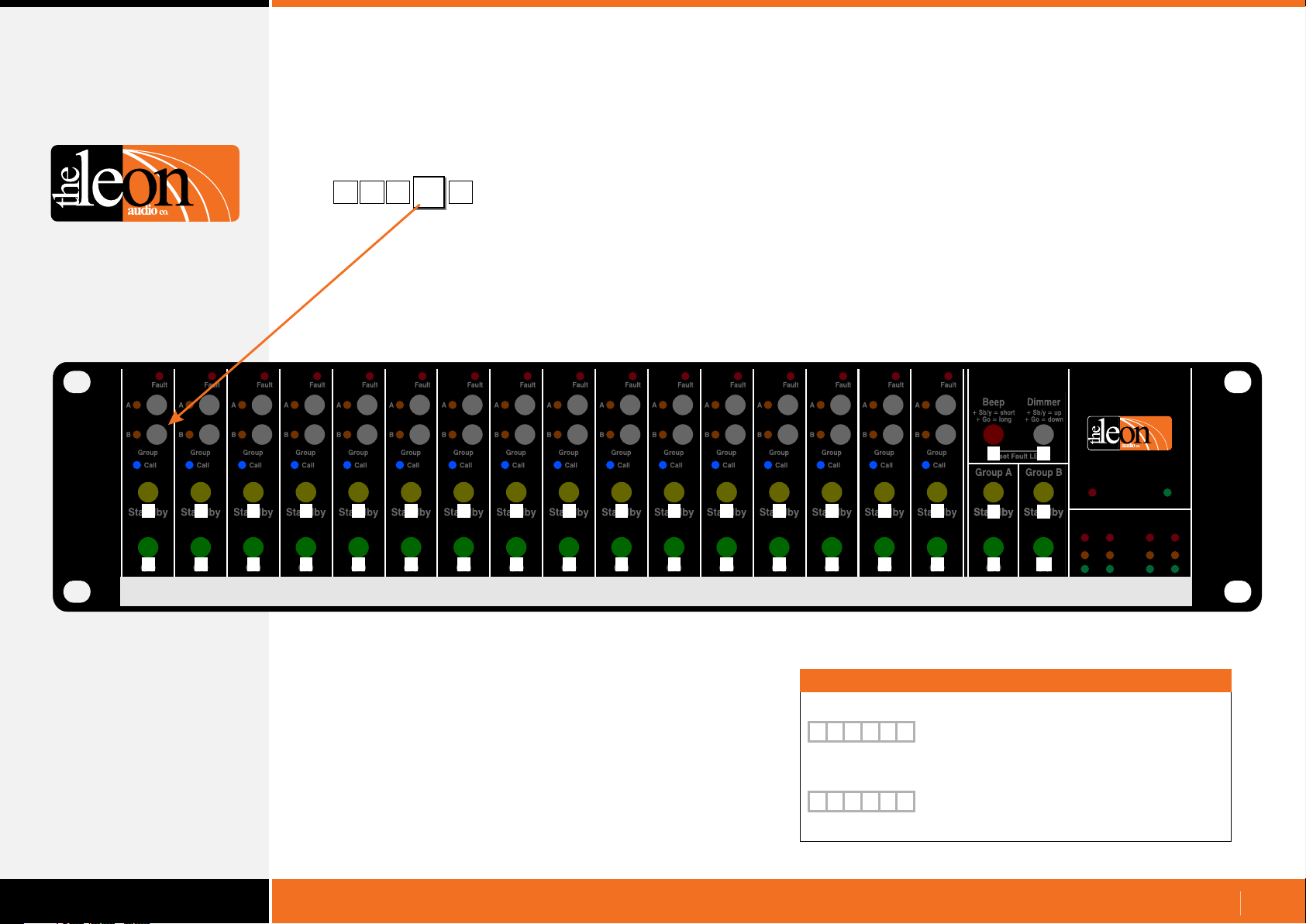
Programming Simple GUI Commands - expanded button number allocation
There wasn’t enough space to use 2 Group buttons on the physical
Master Station but separate Group buttons for Groups A and B are
possible on a touch screen.
[
17
A specific button on the Master Station.
1N4
This is a single byte decimal number in the range of 1 - 87.
It describes a specific button on the Master Station as illustrated
by the yellow numbers below.
Characters in the white boxes are their case sensitive ASCII
equivalents.
1 2 3 4 5 6 7 8 9 10 11 12 13 14 15 16
Fault
A A A A A A A A A A A A A A A A
1 2
B B B B B B B B B B B B B B B B
17 18 19 20 21 22 23 24 25 26 27 28 29 30 31 32
Group
Call Call Call Call Call Call Call Call Call Call Call Call Call Call Call Call
Group
Fault
Group
Fault
3
Group
Fault
4
Group
Fault
5
Group
Fault
6
Group
Fault
7
Fault
Fault
8 9 10
Group
Group
Group
Fault
Fault
11 12
Group
Group
Fault
Group
Fault
13
Group
Fault
14
Fault
15 16
Group
50 51 52 53 54 55 56 57 58 59 60 61 62 63 64 65
Standby
Standby
2 3 4 5 6 7 8 9
Standby
Standby
Standby
Standby
Standby
Standby
Standby
:
;
Standby
66 67 68 69 70 71 72 73 74 75 76
B
GO
C
GO
D E F G H I J K L M N O P Q
GO
GO
GO
GO
GO
GO
GO
GO
Standby
Standby
< = > ?
GO
77
GO
Standby
78 79 80 81
GO
Standby
GO
@
Standby
GO
Fault
Group
Standby
A
GO
Beep Dimmer
+ Sb/y = short
+ Go = long
+ Sb/y = up
+ Go = down
82 83
R S
Reset Fault LEDs
Group A Group B
84 85
Standby Standby
Standby Standby
T
U
86 87
V W
GO GO
GO GO
Cue Light
Master
QLM16 Mk4
www.LeonAudio.com.au
Short Power
Sensors
1 2 3 4
Fault
Unsafe
Safe
Each horizontal row of 16 buttons (channels 1-16) uses
consecutive numbers. Number 33 is not used as it is reserved.
Examples
Button Pressed
[
4 N
17
X
1
Button Released
[
4 N
17
X
0
Master 4, N = Simple GUI command,
Button 17(Ch1 Grp B), 1 = Pressed, eXecute.
Master 4, N = Simple GUI command,
Button 17(Ch1 Grp B), 0 = Released, eXecute.
www.LeonAudio.com.au
09.
Page 10
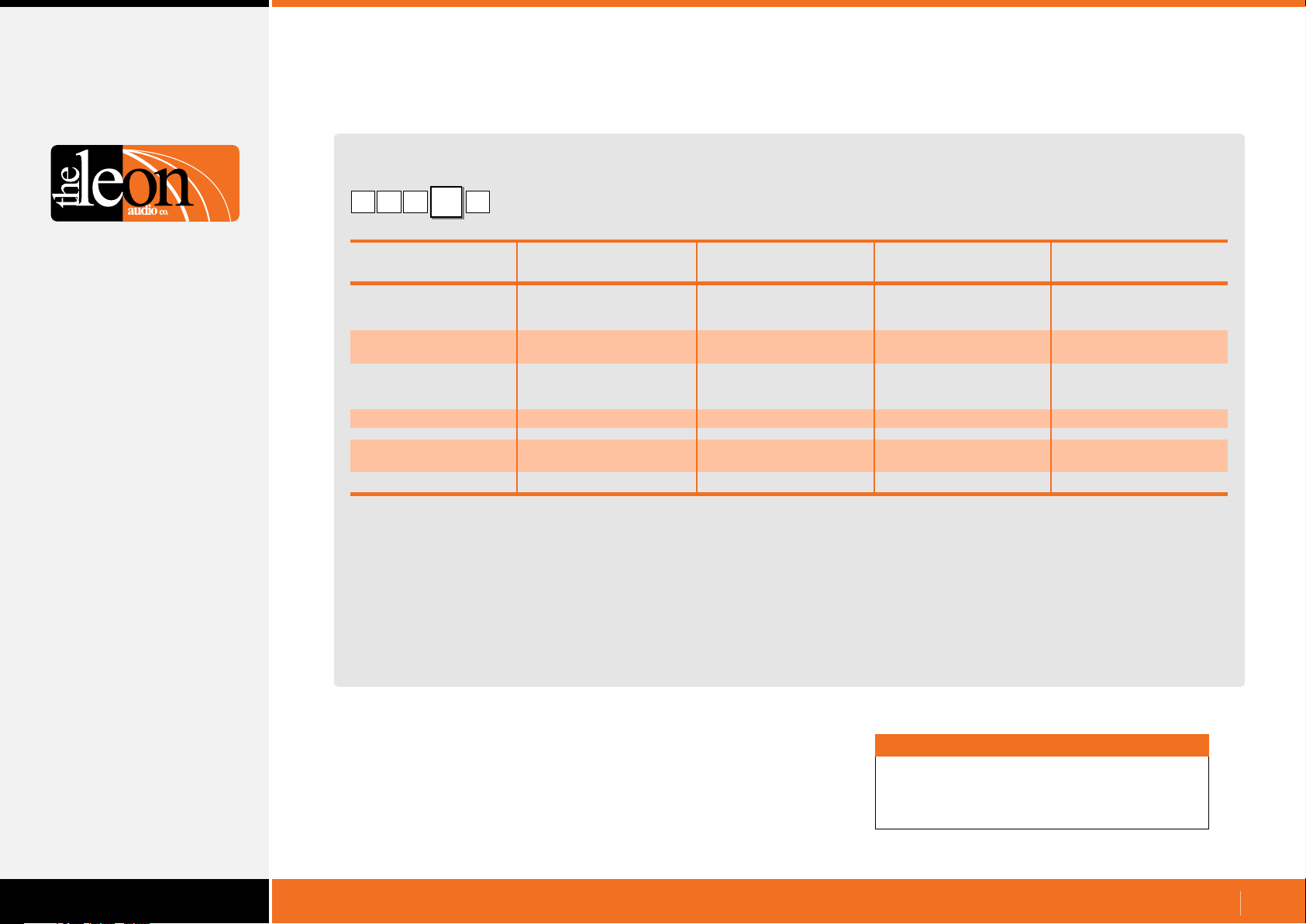
Programming Simple GUI Commands
Table of Button numbers
[
66
A specific button on the Master Station
1N4
Channel 1 2 3 4 5 6 7 8 9 10 11 12 13 14 15 16
Touch Screen’s
Soft buttons
Group A 1 2 3 4 5 6 7 8 9 10 11 12 13 14 15 16
Group B 17 18 19 20 21 22 23 24 25 26 27 28 29 30 31 32
Master Station’s
Grey group buttons
Group Buttons 34 35 36 37 38 39 40 41 42 43 44 45 46 47 48 49
S/by Buttons 50 51 52 53 54 55 56 57 58 59 60 61 62 63 64 65
Go Buttons 66 67 68 69 70 71 72 73 74 75 76 77 78 79 80 81
Other buttons
Red Beep Button 82
White Dimmer Button 83
Group Master Buttons
Group A Standby 84
Group B Standby 85
Group A Go 86
Group B Go 87
Each horizontal row of 16 buttons (channels 1-16) uses consecutive numbers.
Number 33 is not used as it is reserved.
Note
Each number is a single byte decimal number
in the range of 1 - 87.
www.LeonAudio.com.au
10.
Page 11
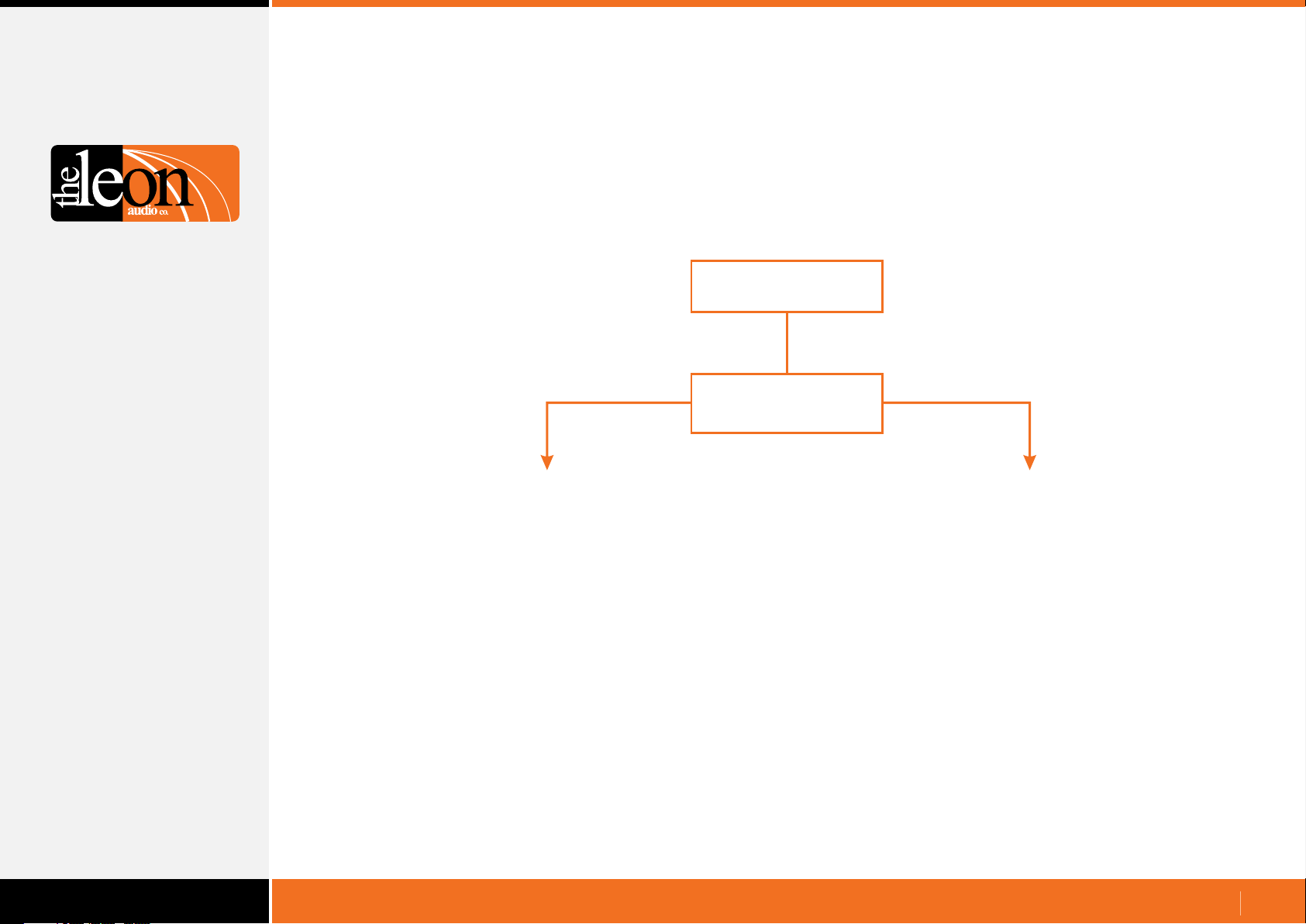
Startup in Simple GUI mode
Either the Touch Screen Controller or the Cue Light
system will boot up first.
Both cases needed to be handled slightly differently.
Touch Screen
power-up
Yes
Is the PCinterface sending
the Heartbeat signal
{RRH1 every second?
Cue Lights Touch Screen Controller are running when starts.
Request the Lamp Status for all channels [1SQ1 to update the
display on the touch screen.
No
Touch Screen Controller is running when Cue Lights start.
There is nothing special to do in this case.
When the PCinterface starts, data for any lamps that are lit will
be sent once. This will update the display on the touch screen.
www.LeonAudio.com.au
11.
Page 12
Cue Sheet Commands
For use with a show control system with a pre-loaded cue list.
The control system sends a command(s) to the PCinterface
when the Next cue button is pressed. It either triggers or
clears a Go or Standby cue (if a cue is already triggered, it will
remain triggered i.e. it does not toggle as in Simple GUI).
Programming Cue Sheet Commands
Programming is done via your show control system (e.g. AMX or
Medallion etc).
All text and numbers are ASCII. Letters are not case sensitive.
5
1
[
Header character to mark the start of a command.
[
1
Up to 6 Master Stations can be controlled by one PCinterface.
The Master Station’s address is set to 1 when shipped.
To change the address, please see Master Station options under
Configuration Editor in the PDF file 16 Channel Cue Light Mk4.
G
5
G
Operate Command Header
1
Master Station Address (0-6)
1
Master’s Address
All Masters
0
Master #1
1
Master #2
2
Master #3
3
Master #4
4
Master #5
5
Master #6
6
Important
All commands must be followed by the letter X for eXecute.
Once X has been received by the PCinterface, the
commands are uploaded to the Master Station(s).
Multiple commands may be entered followed by a single X.
www.LeonAudio.com.au
12.
Page 13
Cue Sheet Commands
Channel Number
•
[
The basic channel address is a single byte.
It can be entered as a decimal number 00d to 16d or as an
ASCII character.
G1
5
ASCII
0
1
2
3
4
5
6
7
8
9
A
B
C
D
E
F
G
Y
Z
Letters are not case sensitive.
Channel Number
1
Decimal
00d
01d
02d
03d
04d
05d
06d
07d
08d
09d
10d
11d
12d
13d
14d
15d
16d
-
-
Channel
All Channels
Channel
Channel 2
Channel 3
Channel 4
Channel 5
Channel 6
Channel 7
Channel 8
Channel 9
Channel 10
Channel 11
Channel 12
Channel 13
Channel 14
Channel 15
Channel 16
Group A Master
Group B Master
1
Additional options for the channel number
•
For ASCII Channel Numbers.
These options are enclosed in round brackets.
No spaces are allowed.
ASCII Channel Number
[
)
(
12
( )
1,3,5
( )
1-5
The channel options above can be used in any combination.
[
[
[
[
Double digit channel numbers.
Multiple channels selected.
A range of channels selected.
( )
8,11
( )
8-11
( )
1,3,9-11,15
( )
1-3,9,14-16
5
Channels 8 and 11
1
G1
Channels 8, 9, 10, and 11
1
G1
1
G1
Channels
1
G1
G1
1, 3, 9, 10, 11 &15
Channels
1
1, 2, 3, 9, 14, 15 & 16
www.LeonAudio.com.au
13.
Page 14
Cue Sheet Commands
Function
G
GO Cue
S
S/by Cue
C
Clear any Cues
B
Sound the Beeper
P
Channel's Group Button
F
Reset Fault Lamps
Summary of
Cue Sheet Commands
Functions and Values
•
[
Go Cue
[
1
G
G
S
C
B
P
F
Details for each of these functions follows.
G5
1
Function
151
Functions
GO Cue
S/by Cue
Clear any Cues
Sound the Beeper
Channel's Group Button
Reset Fault Lamps
Go Cue
Value
Value
0 or C
1 or T
Go Cue
Clear
Trigger
Standby Cue
•
S/by Cue
Value
[
1
Either a letter or a number can be used for the ASCII Value.
Use which ever you prefer. Letters are not case sensitive.
S5
1
Value
0 or C
1 or T
S/by Cue
Examples
[
5
S
1
[
1
[
1
Clear any Cues
•
Same as Go = Clear and S/by = Clear but in a single command.
[
1
( )
12
( )
8-14
C5
1
S
S
Master 1, Ch 5, S/by Cue, Trigger.
0
Master 1, Ch 12, S/by Cue, Clear.
T
Master 1, Ch 8-14, S/by Cue, Trigger.
Clear any Cues
Value
0
Value
0 or C
Any Cue
Clear
Trigger
Clear
Either a letter or a number can be used for the ASCII Value.
Use which ever you prefer. Letters are not case sensitive.
Examples
[
5
G
1
[
1
[
1
( )
12
( )
8-14
G
1
G T
Master 1, Ch 5, Go Cue, Trigger.
0
Master 1, Ch 12, Go Cue, Clear.
Master 1, Ch 8-14, Go Cue, Trigger.
Either a letter or number can be used for the ASCII Value.
Use which ever you prefer. Letters are not case sensitive.
Examples
[
5
C
1
[
1
A shortcut:-
[
0 0
( )
12
0
Master 1, Ch 5, Clear Cues, Clear.
S
0
Master 1, Ch 12, Clear Cues, Clear.
C
C
Clear all cues on all channels of all Masters
www.LeonAudio.com.au
14.
Page 15
Cue Sheet Commands
Functions and Values
Function
G
GO Cue
S
S/by Cue
C
Clear any Cues
B
Sound the Beeper
P
Channel's Group Button
F
Reset Fault Lamps
Summary of
Cue Sheet Commands
Sound the Beeper
•
Beeper
Value
[
1
Note 1
A beep of 5mS duration is so short that it is heard as a click.
Letters are not case sensitive.
Either a letter or numbers can be used for the ASCII Value of the
last 7values. Use which ever you prefer.
Values of A-G can be replaced by a double digit number inside
curved brackets
B5
1
Value Beep Duration
0
1
2
3
4
5
6
7
8
9
A or (10)
B or (11)
C or (12)
D or (13)
E or (14)
F or (15)
G or (16)
5 mS
60mS
120 mS
180 mS
240 mS
300 mS
360 mS
420 mS
480 mS
540 mS
600 mS
660 mS
720 mS
780 mS
840 mS
900 mS
960 mS
(
Note 1
)
Channel’s Group Button
•
Group Button
Value
[
1
5
P
A
Control these 2 Lamps on
the Master Station(s)
Value Group Button
A
B
C
D
E
F
G
0 or K
Letters are not case sensitive.
Either a letter or a number can be used for the ASCII Value of the
kill command. Use which ever you prefer.
A on, B off
B on, A off
A on, B on
A on, B unchanged
A off, B unchanged
B on, A unchanged
B off, A unchanged
A off, B off (kill)
Examples
[
5
1
[
( )
12
1
[
( )
8-14
1
Examples
[
2
B
B
Master 1, Ch 5, Beeper, 120mS duration.
( )
15
Master 1, Ch 12, Beeper, 900mS duration.
F
B
Master 1, Ch 8-14, Beeper, 900mS duration.
5
A
P
1
[
( )
P
12
1
[
( )
8-14
1
Master 1, Ch 5, Group A on, B off
D
Master 1, Ch 12, Group A on, B unchanged
0
P
Master 1, Ch 8-14, Group A & B off
www.LeonAudio.com.au
15.
Page 16

Cue Sheet Commands
Miscellaneous Commands
Reset Flashing Fault Lamps
•
Header
Master Number (0-6)
Miscellaneous Command
Reset Flashing Fault Lamps
Fixed value (no choices)
Function
G
GO Cue
S
S/by Cue
C
Clear any Cues
B
Sound the Beeper
P
Channel's Group Button
F
Reset Fault Lamps
Summary of
Cue Sheet Commands
[
1 1
Reset all flashing Fault Lamps on the Master Station(s).
The Fault Lamp(s) will flash when all Outstations are
disconnected from a channel.
This command will not turn off any Fault Lamps that are burning
steady. A steady Fault Lamp is an indication that the channel has
no Normal mode Outstation connected but has one or more
Eavesdrop mode Outstations connected.
To turn off steady Fault Lamps, connect one Outstation set to
Normal mode to the channel in question.
FS
Example
[
S F
0
1
Reset all flashing Fault Lamps on all
Master Stations.
www.LeonAudio.com.au
16.
Page 17
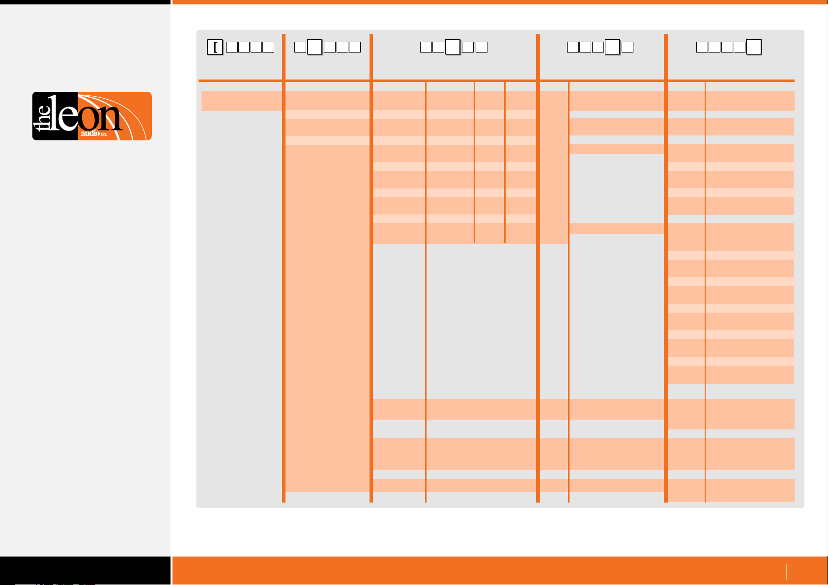
Table of Cue Sheet Commands
4 G 15
Operate
Commands
Header Byte GSGO Cue
(Left square bracket)
[
4
Master
number Channel number
0 (Global)
15 G 1[G4
0 (Global)
1
2
3
4
5
6
10
11
12
13
14
15
16
5 G 1
ASCII Dec Hex Description Description
0
1
2
3
4
5
6
7
8
9
Y
Z
1
2
3
4
5
6
7
8
9
A or (10)
B or (11)
C or (12)
D or (13)
E or (14)
F or (15)
G or (16)
Notes 1, 2
Description
Group A Master buttons
Group B Master buttons
00d
01d
02d
03d
04d
05d
06d
07d
08d
09d
10d
11d
12d
13d
14d
15d
16d
Note 4
00h
01h
02h
03h
04h
05h
06h
07h
08h
09h
0Ah
0Bh
0Ch
0Dh
0Eh
0Fh
10h
[
Function
S/by Cue
C or K
Clear any Go or S/by cue
with a commandsingle
P
Channel's Group
B
Sound the Beeper Beep Duration
GSGo Master
S/by Master
154
[
G54
Value
0 or C
1 or T
0 or C
0 or K
A or (10)
B or (11)
C or (12)
D or (13)
E or (14)
F or (15)
G or (16)
Note 1
0 or C
1 or T
Clear
Trigger
Clear
A
A on, B off
B
B on, A off
C
A on, B on
D
A on, B unchanged
E
A off, B unchanged
F
B on, A unchanged
G
B off, A unchanged
A off, B off (kill)
0
5 mS (click)
1
60mS
2
120 mS
3
180 mS
4
240 mS
5
300 mS
6
360 mS
7
420 mS
8
480 mS
9
540 mS
600 mS
660 mS
720 mS
780 mS
840 mS
900 mS
960 mS
Clear
Trigger
E
Toggle
S Miscellaneous commands Q
N Note 3
Simple GUI (Number) mode 1-87d
Request Lamp Status
for all channels
F Reset Fault Lamps
Button’s number
Note 1: Double digits can be in round brackets e.g. (12)
Note 2: Multiple channels in round brackets e.g. (1,2,3) or (5-15)
Note 3: Simple GUI mode. Each button has been assigned a decimal number. See pages 8-10 for details.
Note 4: Channel number can be ASCII characters or a decimal number 00d to 16d.
Fixed value
1
Button pressed
1
Button released
0
www.LeonAudio.com.au
17.
Page 18
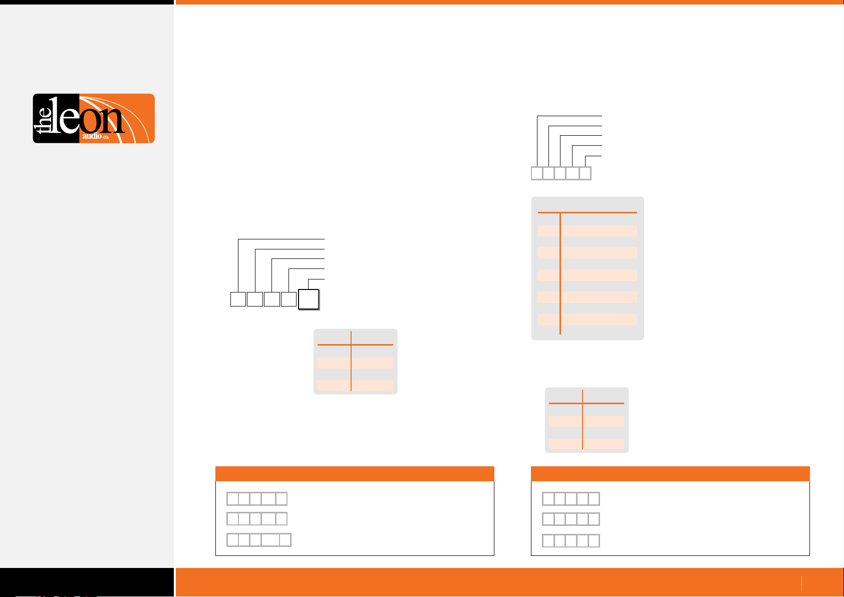
Return Monitoring
When ever there is a change in state of any lamp on the Master
Station, return data showing the state of that lamp is sent from
the PCinterface to the Show Controller.
This data can be in one of two formats:Simple GUI Reply and Channel & Function Reply.
The PCinterface is shipped with the Simple GUI Reply set as
the default. To change the reply format, see Monitoring Reply
Mode command on the following page.
Simple GUI Reply
•
A simple monitoring interface for use with touch screens.
Header
Master Number (1-6)
Simple GUI Reply
Lamp Number (1-119)
Value (0-3)
[
1
N
92
Each lamp has been allocated a single byte decimal number in
the range of 1-119. See pages 22 and 23 for details.
While there are only 112 lamps, some numbers are not used.
Simple GUI Reply
1
Value
0
1
2
3
Lamp
Off
On
Flashing
Dimmed
Channel & Function Reply
•
A monitoring interface using all ASCII characters.
Its primary application is for debugging.
Header
Master Number (1-6)
Channel number (1-9, A-G, S & T-W)
Function (Fault, Go, S/by etc)
Value (0-3)
[
5
G
1
1-9
A
B
C
D
E
F
G
S
T-W
The Function varies depending on the letter in the Channel
Number position. Refer to the table on page 24 for details.
1
Channel & Function Reply
Channel Number
Channels 1-9
Channel 10
Channel 11
Channel 12
Channel 13
Channel 14
Channel 15
Channel 16
Group Masters
& Short Lamp
Sensors 1-4
Value
0
1
2
3
Lamp
Off
On
Flashing
Dimmed
Additional letters are used in the
Channel Number position to
indicate lamps other than those
of the 16 channels.
S indicates the Group Master
lamps and the Short lamp.
T-W are used to indicate the 4
Sensor channels.
Simple GUI Reply Example
[
[
[
67
N
1
1
1
0
83
3
N
100
N
Master 1, Ch 2 Standby lamp, Off
Master 1, Group B Master lamps, Dimmed
2
Master 1, Ch 9 Go lamp, Flashing
Channel & Function Reply Example
[
[
[
1
1
1 9
S
2
0
B
3
S
G
2
Master 1, Ch 2, Standby lamp, Off
Master 1, Group B Master lamps, Dimmed
Master 1, Ch 9, Go lamp, Flashing
www.LeonAudio.com.au
18.
Page 19
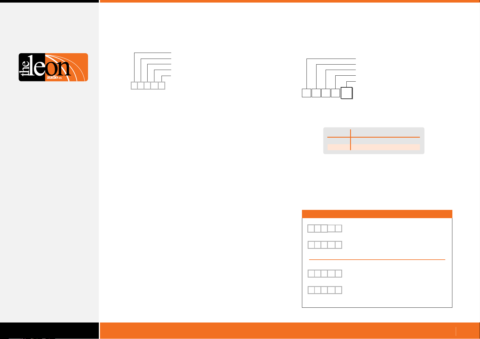
Return Monitoring
Request Lamp Status
•
Header
Master Number (0-6)
Miscellaneous Command
Request Lamp Status
Fixed value (no choices)
[
S
Q
1
Request the Lamp Status for all channels on a specified Master.
Status data for each of the 112 Lamps is sent from the
PCinterface to the Show Controller.
Typical use is to update the display on a touch screen controller.
This data can be in one of two formats:Simple GUI Reply and Channel & Function Reply.
See previous page for details.
To change the reply format, see Monitoring Reply Mode
command opposite.
1
Request Lamp Status command
Monitoring Reply Mode command
•
Configuration Header
PCinterface configuration (fixed value)
PCinterface configuration (fixed value)
Monitoring Reply Mode
Value (0-1)
{
Select the data format for Simple GUI Reply or Channel &
Function Reply status monitoring.
This command configures the PCinterface and is remembered
when the power is off.
It does not require the X for eXecute as it is not uploaded to the
Master Station.
It will execute as soon as the 5th byte Value has been received.
RCR
Value Command
0
1
Monitoring Reply Mode
0
Simple GUI Reply
Channel & Function Reply
Examples
{
R C R
[
N
1
{
R C R
[
1 1
Command to select
0
Simple GUI Reply mode
92
2
Typical Simple GUI Reply
(Master 1, Ch 1 Go flashing in this example)
1
Command to select
Channel & Function Reply mode.
Typical Channel & Function Reply
G
2
(Master 1, Ch 1 Go flashing in this example)
www.LeonAudio.com.au
19.
Page 20
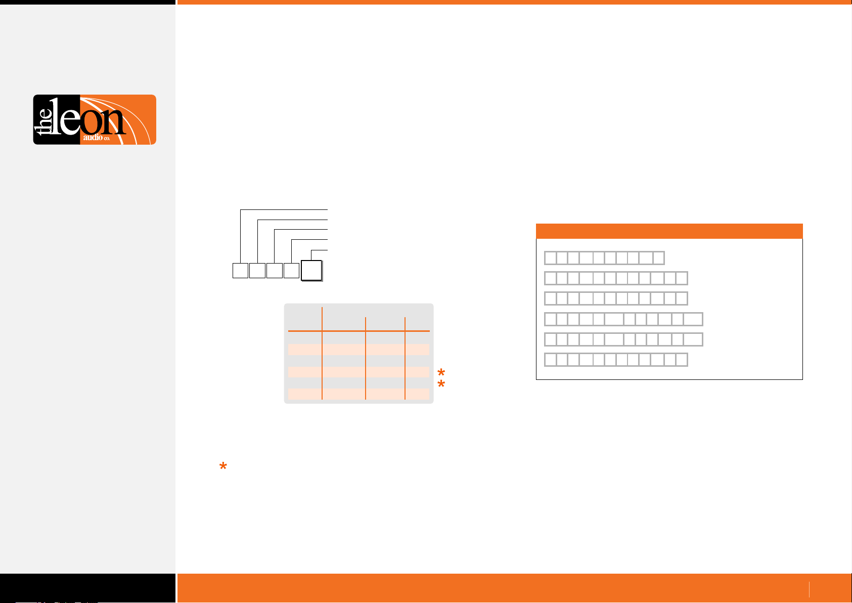
Return Monitoring
Termination Character
•
Each 5 byte monitoring reply can be terminated by a special
character.
There is a choice of 5 different termination characters chosen by
the following command.
This command configures the PCinterface and is remembered
when the power is off.
It does not require the X for eXecute as it is not uploaded to the
Master Station.
It will execute as soon as the 5th byte has been received.
Configuration Header
PCinterface configuration
PCinterface configuration
Termination Character
Termination Character Value (0-5)
{
R
C
T
Value
The default terminator as shipped is none.
<Space> and <LF>
The characters may appear in data sent as
part of the Simple GUI Reply and hence are not suitable choices
for terminator characters intended to be read by a machine (PC).
They are however ideal to aid in readability when data is
displayed on a terminal program.
Termination Character
0
Termination Character
ASCII Decimal Hex
0
1
2
3
4
5
none
}
|
space
line feed
~
none
125d
124d
32d
10d
126d
none
7Dh
7Ch
20h
0Ah
7Eh
The repeating HeartBeat reply {RRH1 is used in the examples below.
Termination Character Examples
{
R R H
{
R
{
R
{
R
{
R
{
R
R
R
R
R
R
{
R R H
1
{
} }
H
1
|
H
1
H
20h 20h
1
H
10h 10h
1
~ ~
H
1
R
R
{
R
R
{
R
{
R
{
R
R
1
H
1
H
1
R
H
1
R
H
1
H
1
No terminator
} Right curly bracket
|
| Pipe
Space
Line Feed
~ Tilde
Use } (125d), | (124d) or ~ (126d) as terminator characters to be
read by a machine (PC) as they are not used within any
commands.
www.LeonAudio.com.au
20.
Page 21
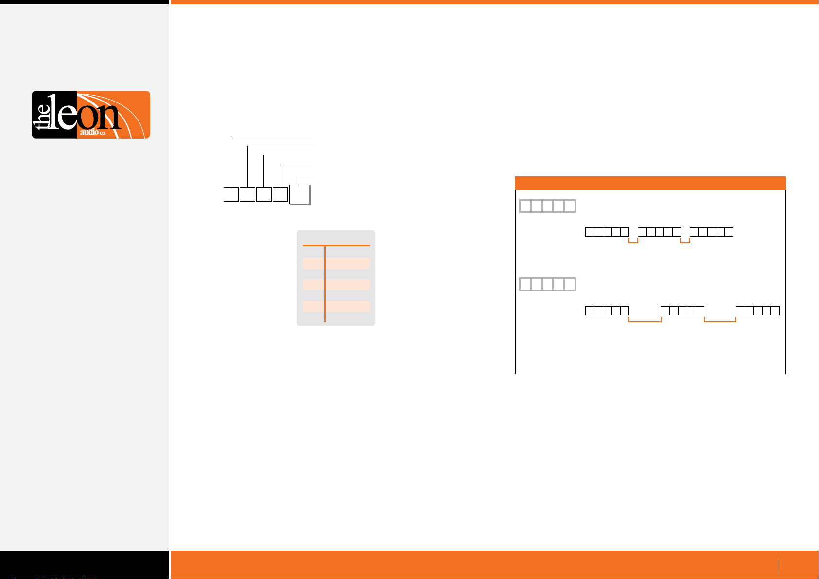
Return Monitoring
Reply Pacing
•
Add a pause between each 5 byte reply if the receiving system is
unable to process the incoming data quickly enough.
Configuration Header
PCinterface configuration
PCinterface configuration
Reply Pacing
Reply Pacing Value (0-6)
{
No response is given when this command is sent.
The new setting is saved when the power is off.
PCR
Reply Pacing
0
Reply Pacing
0
1
2
3
4
5
6
no pause
100uS
300uS
1mS
3mS
10mS
30mS
Examples
{
{
Note:
These drawings are not to scale.
The duration of the 5 byte replies will vary with baud rate.
P
R C
5 byte reply
P
R C
5 byte reply1 5 byte reply
Set Reply Pacing pause to 100uS
1
5 byte reply
1 2 3 4 5 1 2 3 4 5 1 2 3 4 5
100uS min
pause
Set Reply Pacing pause to 1mS
3
2 3 4 5 1 2 3 4 5 1 2 3 4 5
1mS min
5 byte reply
100uS min
pause
pause
5 byte reply
1mS min
pause
Use the shortest pause possible or response times may become
unacceptable.
With Pacing set to 0mS, the Request Lamp Status [1SQ1
command takes 63mS to return 560 bytes of data at 115,200 baud.
With Pacing set to 30mS, the same command takes 3.38 seconds
to return the same data.
www.LeonAudio.com.au
21.
Page 22
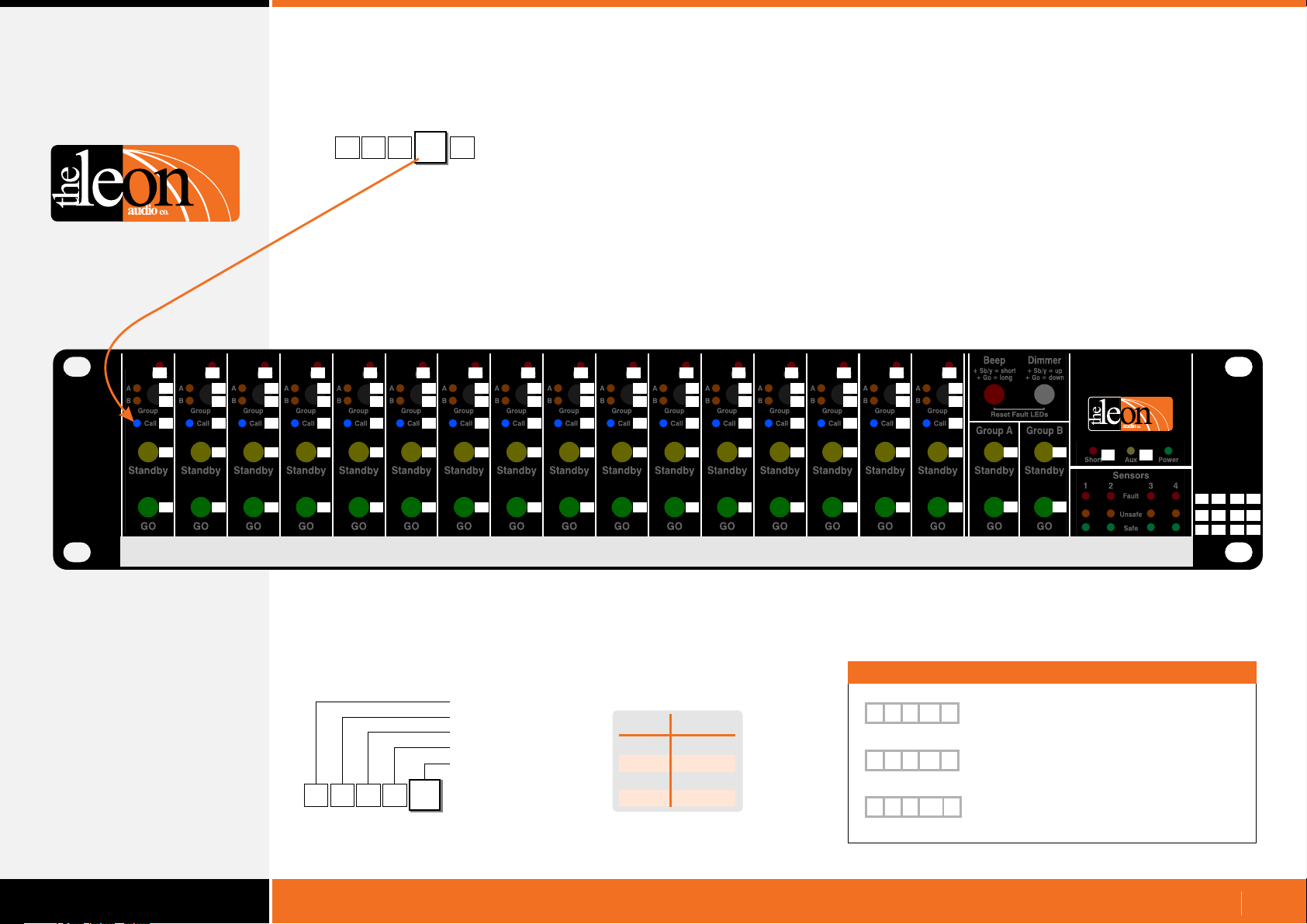
Return Monitoring. Simple GUI Reply format
Lamp number allocation
[
1
N
50
This is a single byte decimal number in the range of 1 - 119.
It describes a specific Lamp. (Ch1 Call lamp in this example).
A specific Lamp on the Master Station.
1
•
Lamp Flash rates
Different lamps flash at different rates on the Cue Light Master.
Fault lamps: 4Hz 50% duty cycle. 120mS on, 120mS off.
Call lamps: 8Hz 50% duty cycle. 60mS on, 60mS off.
Lamp numbers.
•
(includes illuminated Go & Standby buttons)
Yellow numbers are decimal values (1-119) returned as the 4th
byte of return monitoring when using the Simple GUI Reply format.
Values in the white boxes are their ASCII equivalent.
1 2 3 4 5 6 7 8 9
1 2 3 4 5 6 7 8 9 10 11 12 13 14 15 16
SOH STX ETX EOT ENQ ACK BEL BS HT LF VT FF CR SO SI DLE
Fault
A
17 18 19 20 21 22 23 24 25 26 27 28 29 30 31 32
B
34 35 36 37 38 39 40 41 42 43
Group
Call
50 51 52 53 54 55 56 57 58 59 60 61 62 63 64 65
66 67 68 69 70 71
Standby
92
GO
Fault
A
DC1 DC2 DC3 DC4 NAK SYN ETB CAN EM SUB ESC FS GS RS US SP
B
“
Group
Call
2 3 4 5 6 7 8 9 : ; < = > ? @ A
B C D E F G H I J K L M N O P Q
Standby
\ ] ^ _
93
GO
Fault
A
B
# $ % &
Group
Call
Fault
A
B
Group
Call
Fault
A
B
Group
Call
Fault
A
B
Group
Call
Fault
A
B
‘
Group
Call
Fault
A
B
( )
Group
Call
A
B
Group
72 73
Standby
Standby
94 95 96 97 98 99 100 101
GO
GO
Standby
GO
`
Standby
Standby
a b c d e f g h I j
GO
GO
Standby
GO
Standby
Fault
Call
74
GO
*
Fault
A
B
Group
Call
75
Standby
GO
10
11 12 13 14 15 16
Fault
A
B
+
44
Group
Call
Fault
A
,
B
A
B
- . / 0 1
45 46 47 48 49
Group
Group
Call
76 77 78 79 80 81
Standby
102
GO
Standby
Standby
103 104 105 106
GO
GO
Standby lamps: 2.1Hz 63% duty cycle. 300mS on, 180mS off.
Go lamps: 5.6Hz 67% duty cycle. 120mS on, 60mS off.
Standby & Go lamps deliberately use a duty cycle about 2:1 so
that one is less likely to miss a Go or Standby cue when glancing
at the lamp simply because the lamp is on for longer than it is off.
Fault
Call
Fault
A
B
Group
Call
Standby
GO
Fault
A
B
Group
Call
Standby
GO
Each horizontal row of 16 lamps (channels 1-16) uses consecutive
numbers. Numbers 86 through 91 are not used as they are reserved.
Beep Dimmer
+ Sb/y = short
Fault
Call
+ Go = long
Group A Group B
A
B
Group
82 83
107
GO
k
Standby Standby
82 83
GO GO
Standby
Master Group A&B
Lamps light as pairs.
+ Sb/y = up
+ Go = down
Reset Fault LEDs
R
R
Cue Light
Master
QLM16 Mk4
www.LeonAudio.com.au
S
S
T U
84 85
Short Aux Power
Sensors
1 2 3 4
108
109
112
113
116
117
Fault
Unsafe
Safe
110
114
118
111
115
119
l m n o
p q r s
t u v w
[
1
N
92
1
Simple GUI Reply format
Header
Master Number (1-6)
Simple GUI Reply
Lamp Number (1-119)
Value (0-3)
Value
0
1
2
3
Lamp
Off
On
Flashing
Dimmed
Monitoring Status Examples
[
[
[
18
N
1
57
N
2
3
N
107
Master 1, Number Mode,
1
Lamp 18 (Ch2 Group A), 1 = On
Master 2, Number Mode,
2
Lamp 57 (Ch 8 Call), 2 = Flashing
Master 3, Number Mode,
3
Lamp 107 (Ch16 Go), 3 = Dimmed
www.LeonAudio.com.au
22.
Page 23
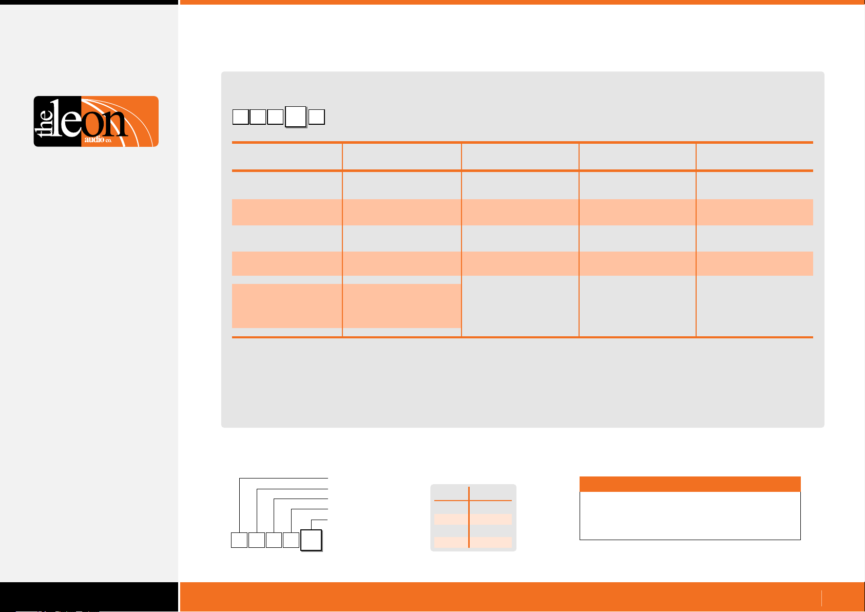
Return Monitoring. Simple GUI Reply format
Table of Lamp numbers
[
1
92
A specific lamp on the Master Station
1N
Channel 1 2 3 4 5 6 7 8 9 10 11 12 13 14 15 16
Fault Lamp 1 2 3 4 5 6 7 8 9 10 11 12 13 14 15 16
Group A Lamp 17 18 19 20 21 22 23 24 25 26 27 28 29 30 31 32
Group B Lamp 34 35 36 37 38 39 40 41 42 43 44 45 46 47 48 49
Call lamp 50 51 52 53 54 55 56 57 58 59 60 61 62 63 64 65
S/by Lamp 66 67 68 69 70 71 72 73 74 75 76 77 78 79 80 81
Go Lamp 92 93 94 95 96 97 98 99 100 101 102 103 104 105 106 107
Sensor Lamps
Fault 108 109 110 111
Unsafe 112 113 114 115
Safe 116 117 118 119
Other Lamps
Group A Master Lamps 82 (S/by & Go buttons light as a pair)
Group B Master Lamps 83 (S/by & Go buttons light as a pair)
Short Lamp 84
Aux lamp 85 (not fitted)
Each horizontal row of 16 lamps (channels 1-16) uses consecutive
numbers. Numbers 86 through 91 are not used as they are reserved.
Header
[
1
N
92
1
Simple GUI Reply format
Master Number (1-6)
Simple GUI Reply
Lamp Number (1-119)
Value (0-3)
Value
0
1
2
3
Lamp
Off
On
Flashing
Dimmed
Note
Each number is a single byte decimal number
in the range of 1 - 119.
www.LeonAudio.com.au
23.
Page 24
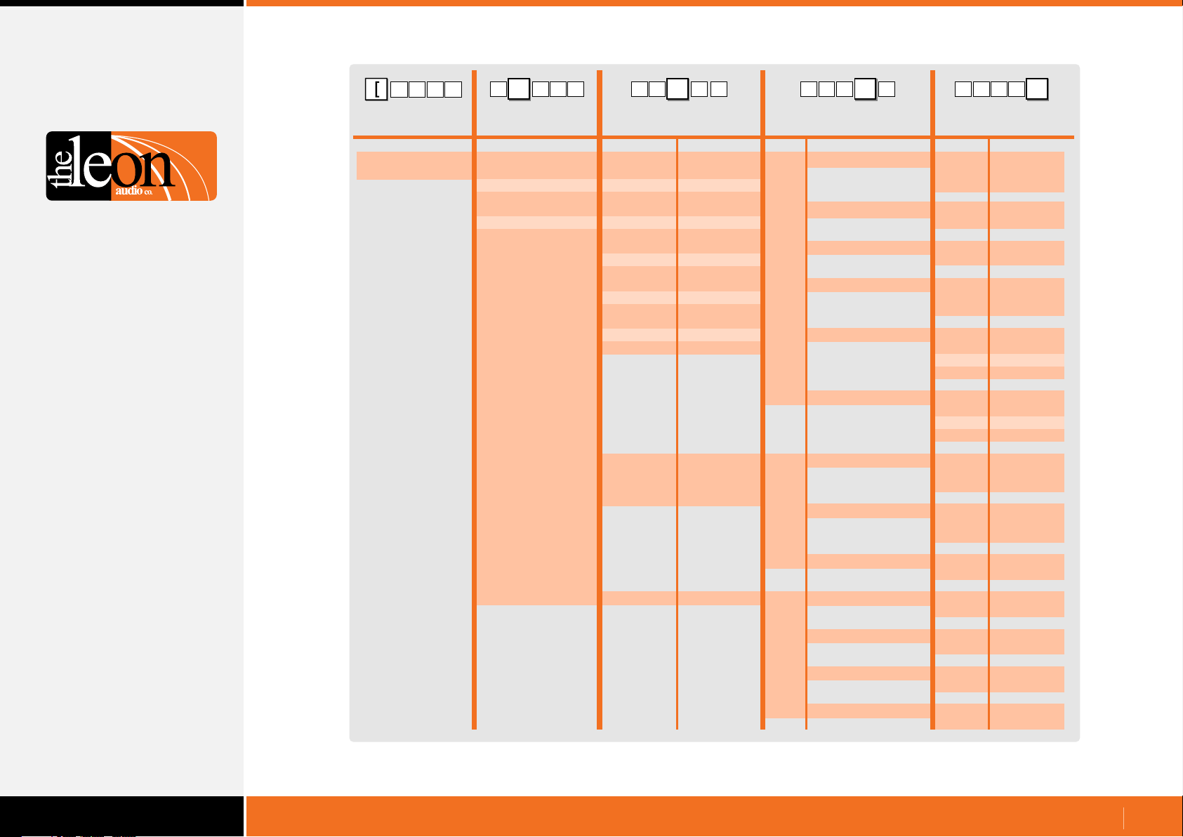
Table of Return Monitoring. Channel & Function format
1 G 15
Operate
Replies
Header Byte
(Left square bracket)
[
1
15 G
[
5
Master
number Channel number
ASCII
1
2
3
4
5
6
1
2
3
4
5
6
7
8
9
10
11
12
13
14
15
16
Sensor 1
Sensor 2
Sensor 3
Sensor 4
Other Lamps
1
G1
[
G
151
Function
ASCII Description Description
1
2
3
4
5
6
7
8
9
A
B
C
D
E
F
G
T
U
V
W
S
F
Fault Lamps
A
Group A Lamps
B
Group B Lamps
C
Call Lamps
S
Standby Lamps
G
Go Lamps
F
Fault Lamps
U
Unsafe Lamps
S
Safe Lamps
A
Group A Master
B
Group B Master
S
Short Lamp
T
Aux Lamp (not fitted)
[
G51
1
Value
0
1
2
0
1
0
1
0
1
2
0
1
2
3
0
1
2
3
0
1
2
0
1
2
0
1
0
3
0
3
0
1
0
1
Off
On
Flash
Off
On
Off
On
Off
On
Flash
Off
On
Flash
Dimmed
Off
On
Flash
Dimmed
Off
On
Flash
Off
On
Flash
Off
On
Off
Dimmed
Off
Dimmed
Off
On
Off
On
www.LeonAudio.com.au
24.
Page 25
Other Return Monitoring
Master’s on-line status
Sent once by the PCinterface when ever a Master Station’s status
changes. The PCinterface may not report a Master Station going offline if the Expansion Port cable is unplugged as the PCinterface is
powered via this cable.
Heart Beat signal
The Heart Beat signal is generated by the PCinterface unit.
It does not indicate that any Cue Light Outstations are connected.
The Heart Beat signal is reset to ON when ever the PCinterface
is powered up.
{
0
1
Examples
{
1 0 S
{
2 0 S
{
Configuration Header
Master number (1-6)
Unused (fixed at 0)
Master’s on-line status
Status Value (0-1)
S
Master’s on-line status
1
Master’s on-line status
Just gone off-line
0
Just come on-line
1
1
Master #1 has just come on-line
R R
This response is sent once every second +/- 5%.
The Heart Beat signal can be turned off but will automatically be
turned back on the next time the PCinterface is powered up.
Heart Beat on/off command
Use this command to turn the Heart Beat signal on or off.
{
0
Master #2 has just gone off-line
Heart Beat signal
H
1
HCR
Configuration Header
PCinterface configuration
PCinterface configuration
Heart Beat on/off
Heart Beat on/off Value (0-1)
Heart Beat on/off command
1
Heart Beat Signal
0
1
Off
On
www.LeonAudio.com.au
25.
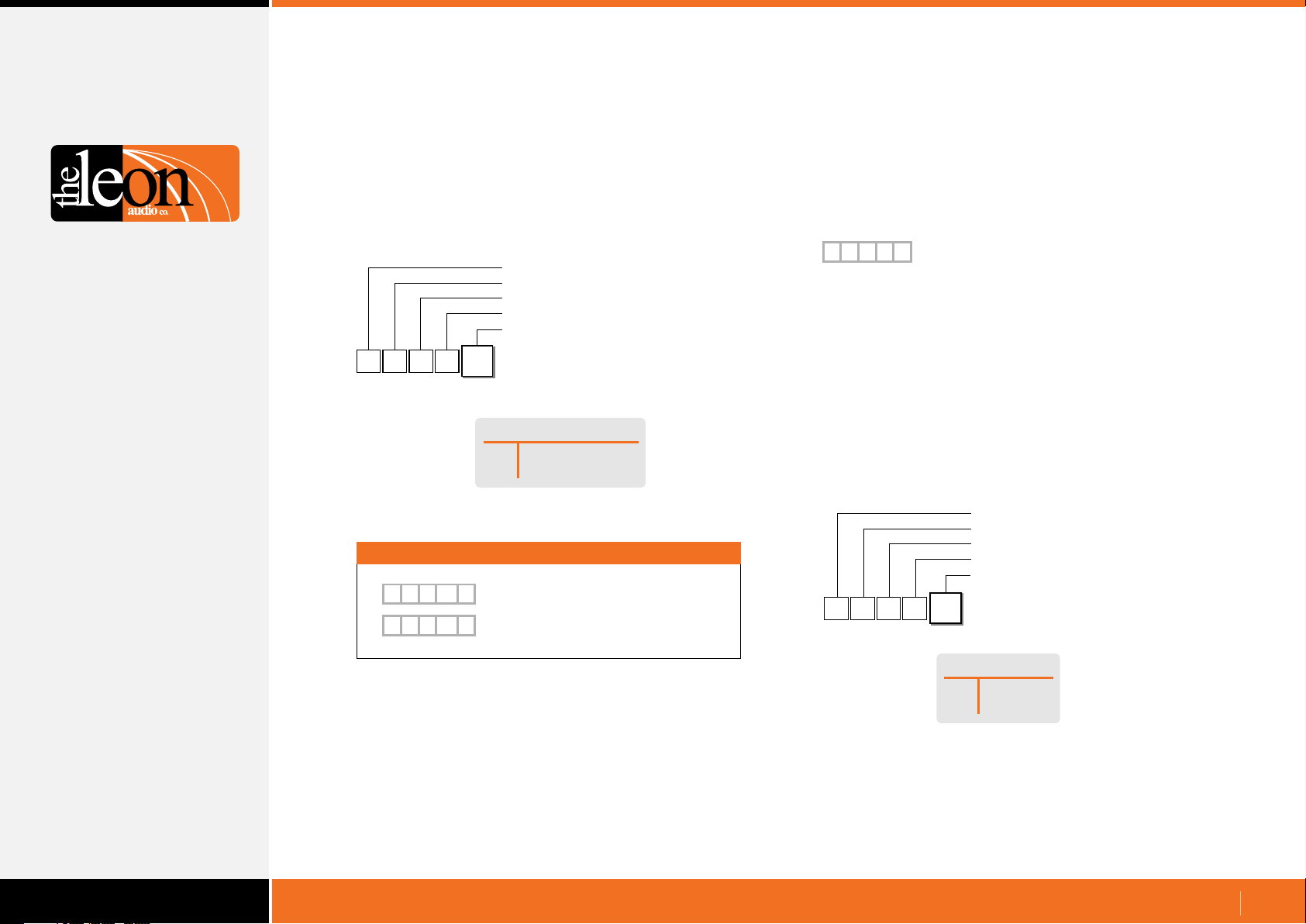
Page 26
Configuration Commands
Many options can be configured for the 3 types of Outstation, Master
Station and PCinterface.
Configuration Command Format
Configuration Command Header
•
All options that can be changed using the Master Station’s
Configuration Editor can also be changed using PCinterface
commands.
All of the configuration settings (options) for a Master Station can also
be downloaded into an editable ASCII text file.
The same text file can then be uploaded to (re)configure the Master
Station and associated Outstations.
Configuration Commands will be covered for the following devices:-
Ÿ Standard Outstation
Ÿ Relay Outstation
Ÿ Contact Sensor
Ÿ Master Station
Ÿ PCinterface
Each configuration option is discussed in detail under
Master Station’s Configuration Editor in the PDF file
16 Channel Cue Light Mk4.pdf
A
5
1
{
Header character to mark the start of a command.
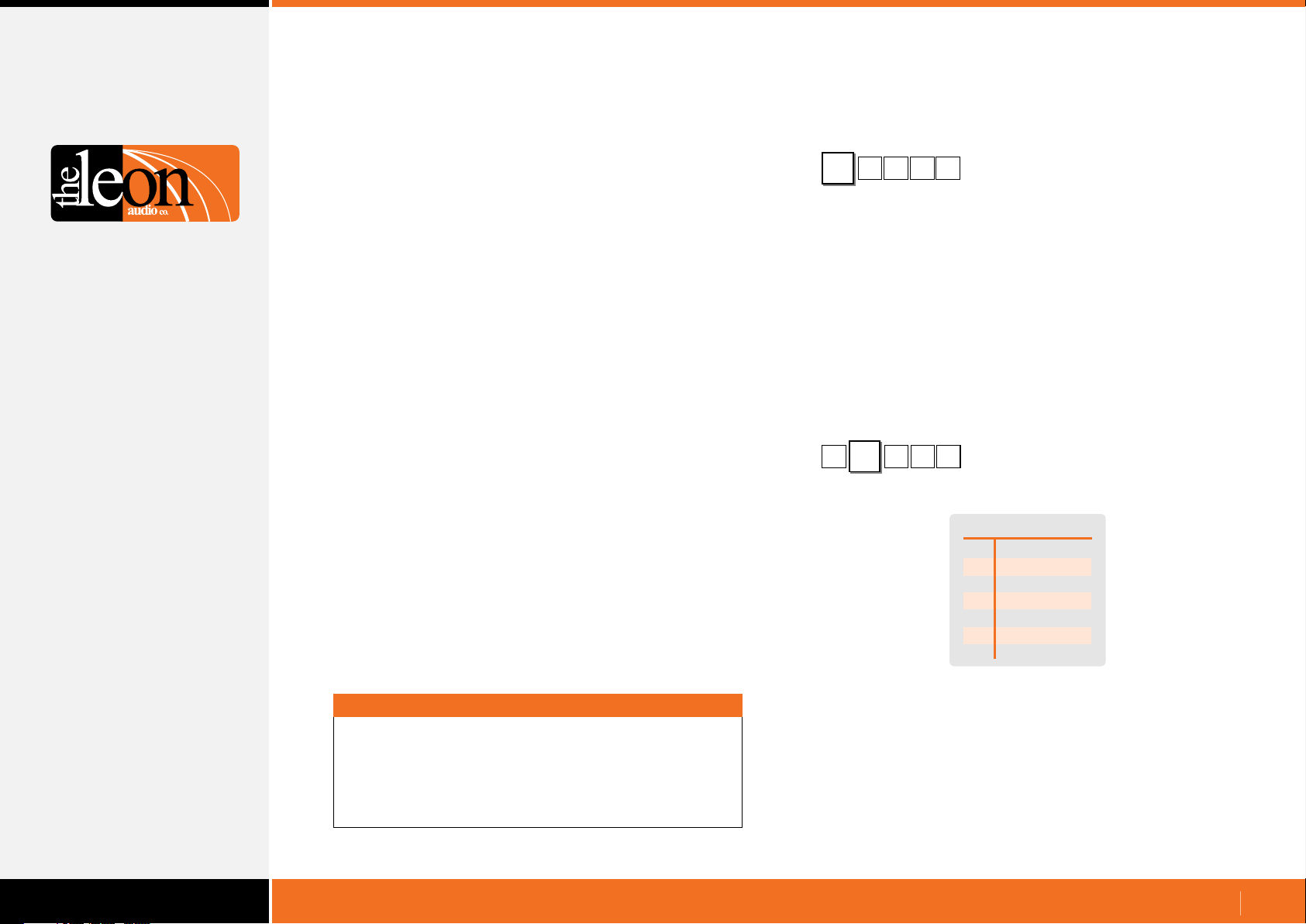
Master Station Address
•
{
Up to 6 Master Stations can be controlled by one PCinterface.
1
5
A
Configuration Command Header
1
Master Station Address (0-6)
1
Master’s Address
All Masters
0
Master #1
1
Master #2
2
Master #3
3
Master #4
4
Master #5
5
Master #6
6
Important
All commands must be followed by the letter X for eXecute.
Once X has been received by the PCinterface, the
commands are uploaded to the Master Station(s).
Multiple commands may be entered followed by a single X.
The Master Station’s address is set to 1 when shipped.
To change the address, please see Master Station options under
Configuration Editor in the PDF file 16 Channel Cue Light Mk4.
www.LeonAudio.com.au
26.
Page 27
Configuration Commands
Configuration Command Format
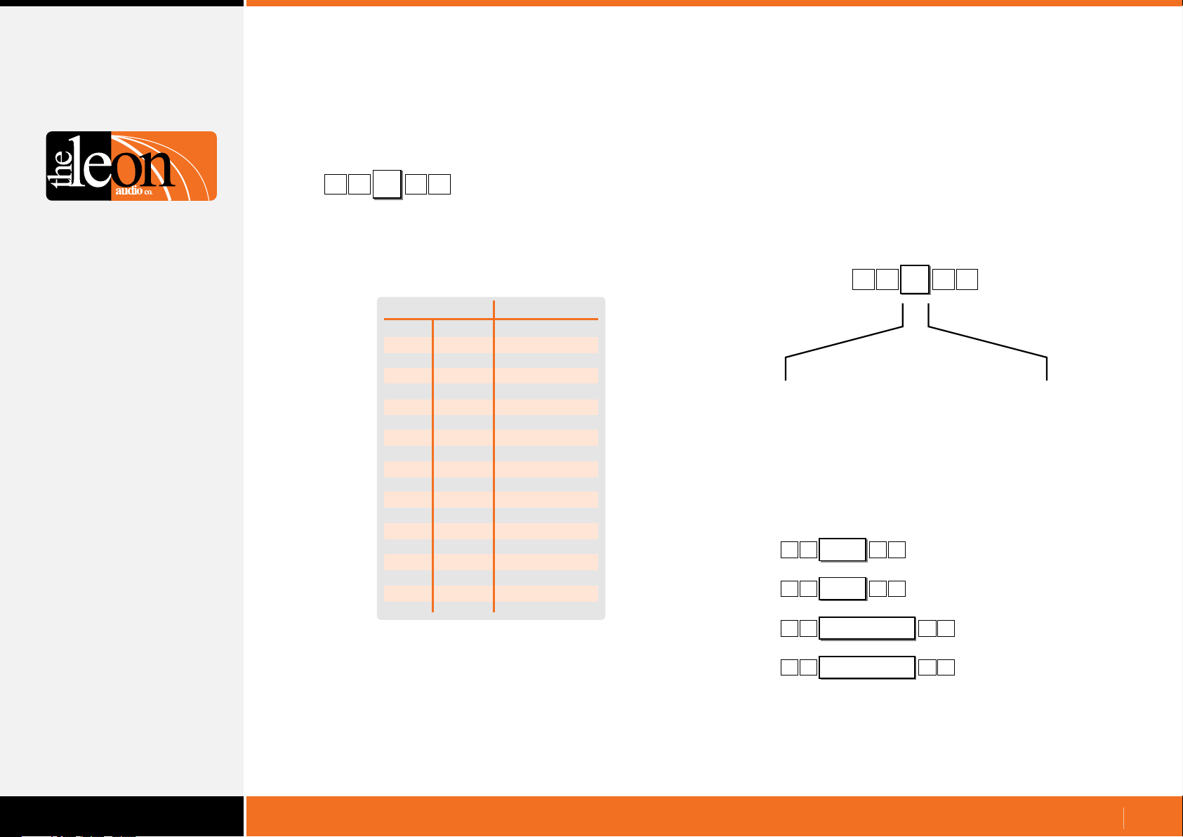
Channel Number
•
[
1
The basic channel address is a single byte.
It can be entered as a decimal number 00d to 16d or as an
ASCII character.
A
5
ASCII
0
1
2
3
4
5
6
7
8
9
A
B
C
D
E
F
G
Y
Z
Letters are not case sensitive.
Channel Number
1
Decimal
00d
01d
02d
03d
04d
05d
06d
07d
08d
09d
10d
11d
12d
13d
14d
15d
16d
-
-
Channel
All Channels
Channel
Channel 2
Channel 3
Channel 4
Channel 5
Channel 6
Channel 7
Channel 8
Channel 9
Channel 10
Channel 11
Channel 12
Channel 13
Channel 14
Channel 15
Channel 16
Group A Master
Group B Master
1
Additional options for the channel number
•
For ASCII Channel Numbers.
These options are enclosed in round brackets.
No spaces are allowed.
ASCII Channel Number
[
)
(
12
( )
1,3,5
( )
1-5
The channel options above can be used in any combination.
[
[
[
[
Double digit channel numbers.
Multiple channels selected.
A range of channels selected.
( )
8,11
( )
8-11
( )
1,3,9-11,15
( )
1-3,9,14-16
5
Channels 8 and 11
1
G1
Channels 8, 9, 10, and 11
1
G1
1
G1
Channels
1
G1
G1
1, 3, 9, 10, 11 &15
Channels
1
1, 2, 3, 9, 14, 15 & 16
www.LeonAudio.com.au
27.
Page 28
Configuration Commands
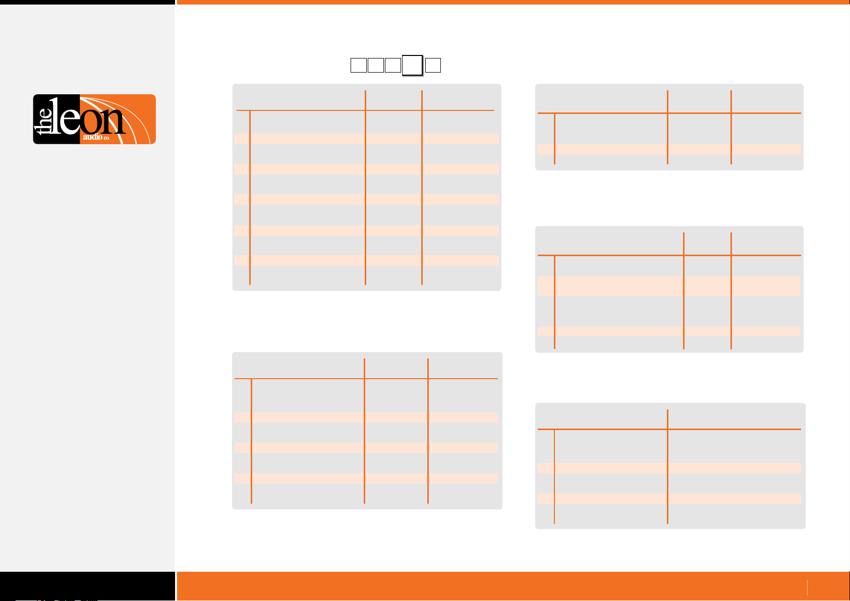
Overview of Functions
(
Function
A
Outstation
B
S/by Flash on Master
C
S/by Flash on Outstation
D
S/by latches
E
S/by Dims on ACK
Outstation Go Flickers
F
Go times out
G
Go flashes
H
Go latches
J
Go & S/by interlocked
K
Call lamp enabled
M
Call lamp flashes
N
ACK button back-light
P
Beeper enable
Q
Beep-on-Go
R
Change colour on ACK
S
Dimmer
T
Cue Light Outstation Functions
Upper Case
S/by colour
{
)
5
1
Factory
Default
Yellow
Flashes
Flashes
Latches
No
Steady
Times out
Flashes
Latches
Interlocked
Enabled
Flashes
On
Enabled
Silent
No change
100%
A
1
User Selectable
Function
Red
Steady
Steady
Momentary
Dims on ACK
Flickers
Stays on
Steady
Momentary
Independent
Call lamp off
Steady
Off
Disabled
Beeps (4 choices)
Change colour
5-100% in 5 steps
Function
1
Unsafe Lamp
2
Safe when... open/closed
3
End Of Line Resistors
4
All Lamps on Outstation
Sensor Outstation Functions
Function
A
Copy 1 of 8 files to PC
B
Copy 1 of 7 files to the
C
E
F
ShowTime file.
Copy ShowTime file to
Installer's Default
or 1 of 4 User files.
Go Cue Total Duration
Link 4 Group Master buttons
Factory
Default
Steady
Open
No EOL
Enabled
Factory
Default
15 Secs
Linked
User Selectable
Function
Flash
Closed
Two EOL
Disabled
User Selectable
Function
1-16 Secs
Not Linked
(
Function
a
Mode
b
S/by Flash on Master
c
S/by Flash on Outstation
d
S/by latches
e
Go times out
f
Go flashes
g
Go latches
h
Go & S/by interlocked
j
Call lamp enabled
k
Call lamp Flashes
m
All Lamps on Outstation
Relay Outstation Functions
Lower Case
)
Factory
Default
Flashes
Flashes
Latches
Times out
Flashes
Latches
Interlocked
Enabled
Flashes
Enabled
User Selectable
Function
5 modes
Steady
Steady
Momentary
Stays on
Steady
Momentary
Independent
Call lamp off
Steady
Off
Master Station Functions
Function
R
Monitoring Reply Mode
B
Baud Rate
H
Heart Beat @ 1Hz rate
P
T
PCinterface Functions
(Idle Character)
Pacing. Pause between
each 5 byte reply
Terminator chx for replies
Values
Simple GUI Reply
or Channel & Function Reply
2400 to 115200
on/off
0uS, 100uS, 300uS, 1mS,
3mS, 10mS, 30mS
None } | <space> <LF> ~
www.LeonAudio.com.au
28.
Page 29
Configuration Commands
Cue Light Outstation Functions
Configuration Header
Master number (0-6)
Channel number (0-9, A-G)
Function
Value (depends on function)
{
A
B
C
D
E
F
G
H
J
K
M
N
P
Q
R
S
T
Summary of Cue Light Outstation Functions
5
1
Outstation
S/by Flash on Master
S/by Flash on Outstation
S/by latches
S/by Dims on ACK
Outstation Go Flickers
Go times out
Go flashes
Go latches
Go & S/by interlocked
Call lamp enabled
Call lamp flashes
ACK button back-light
Beeper enable
Beep-on-Go
Change colour on ACK
Dimmer
A
Function
S/by colour
Cue Light Outstation Functions
0
For Cue Light Outstations,
Function is Upper Case
Factory
Default
Yellow
Flashes
Flashes
Latches
No
Steady
Times out
Flashes
Latches
Interlocked
Enabled
Flashes
On
Enabled
Silent
No change
100%
User Selectable
Function
Red
Steady
Steady
Momentary
Dims on ACK
Flickers
Stays on
Steady
Momentary
Independent
Call lamp off
Steady
Off
Disabled
Beeps (4 choices)
Change colour
5-100% in 5 steps
Standard Cue Light Outstation QLS Mk4
Outstation with Beeper QLS-B Mk4
Beeper and Beep-On-Go options only apply when a Beeper
Outstation (QLS-B) is connected to that channel. Outstations
without a beeper ignore the beeper settings.
Small Footprint Outstation QLS-SM Mk4
www.LeonAudio.com.au
29.
Page 30
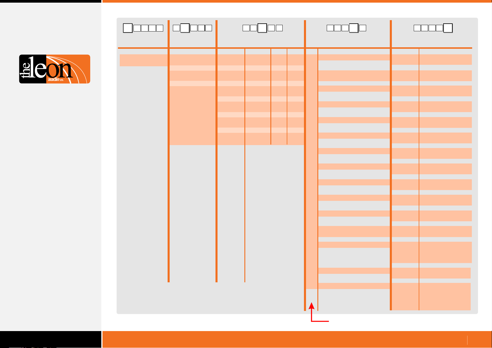
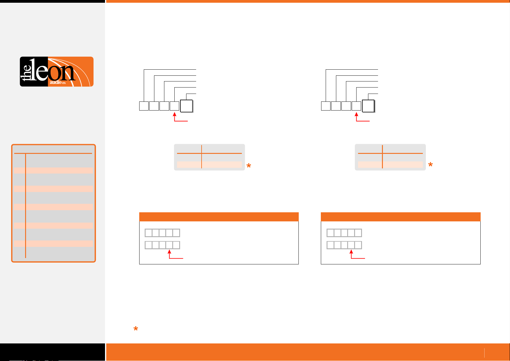
Table of Cue Light Outstation Configuration Commands
A
1
{
Configuration
Commands
Header Byte
(Left curly bracket)
{
15
1
15 A
{
A1
5
1
{
A
151
{
A51
1
Master
number Channel number
ASCII Dec Hex Description Description
0 (Global)
1
2
3
4
5
6
0 (Global)
1
2
3
4
5
6
7
8
9
10
11
12
13
14
15
16
0
1
2
3
4
5
6
7
8
9
A or (10)
B or (11)
C or (12)
D or (13)
E or (14)
F or (15)
G or (16)
Note 1
00d
01d
02d
03d
04d
05d
06d
07d
08d
09d
10d
11d
12d
13d
14d
15d
16d
Note 2
00h
01h
02h
03h
04h
05h
06h
07h
08h
09h
0Ah
0Bh
0Ch
0Dh
0Eh
0Fh
10h
Function
Outstation’s Standby Colour
A
Standby Flash on Master
B
Standby Flash on Outstation
C
Standby Latches
D
Standby DIMs on Acknowledge
E
Outstation Go Flickers
F
Go Times-out
G
Go Flashes
H
Go Latches
J
Go & S/by Interlocked
K
0 or R
1 or Y
0 or S
1 or F
0 or M
1 or F
0 or N
1 or D
0 or S
1 or F
0 or N
1 or T
0 or S
1 or F
0 or M
1 or L
0
1
Value
Red
Yellow
Steady
Flash
Momentary
Latches
No DIM on ACK
DIM on ACK
Steady
Flicker
No time-out
Times-out after delay
Steady
Flashes after 3 secs.
Momentary
Latches
Independant
Interlocked
Note 1:
Double digits can be in round brackets e.g. (12)
Multiple channels in round brackets e.g. (1,2,3) or (5-15)
Note 2: Channel number can be a decimal number 00d to 16d
or ASCII characters.
Call Lamp Enabled
M
Call lamp Flashes
N
Acknowledge button backlight
P
Beeper Enable
Q
Beep-On-Go
R
S/by Change Colour on ACK
S
Dimmer
T
This Column is Upper Case
0 or D
1 or E
0 or S
1 or F
0 or F
1 or N
0
1
2
3
0 or N
1 or C
1
2
3
4
5
Disabled
Enabled
Steady
Flashes
ofF
oN
Off
1mS
50mS
200mS
No Colour Change
Change Colour
5%
25%
50%
75%
100%
www.LeonAudio.com.au
30.
Page 31
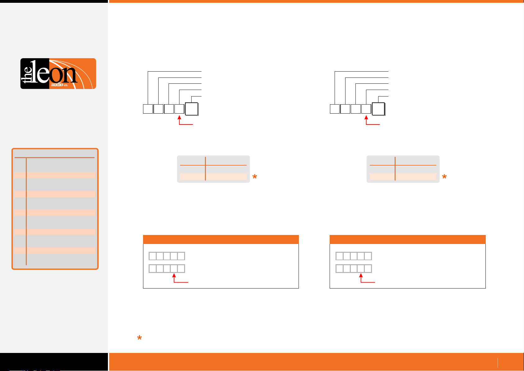
Configuration Commands
Cue Light Outstation Functions
Function
Outstation S/by colour
A
S/by Flash on Master
B
S/by Flash on Outstation
C
S/by latches
D
S/by Dims on ACK
E
F
Outstation Go Flickers
G
Go times out
H
Go flashes
J
Go latches
K
Go & S/by interlocked
M
Call lamp enabled
N
Call lamp flashes
P
ACK button back-light
Q
Beeper enable
R
Beep-on-Go
S
Change colour on ACK
T
Dimmer
Summary of Cue Light
Outstation Functions
Outstation’s Standby Colour
•
Configuration Header
Master number (0-6)
Channel number (0-16)
Outstation’s Standby Colour
Value
{
Either a letter or a number can be used for the ASCII Value.
Use which ever you prefer. Letters are not case sensitive.
5
1
A
1
Function is Upper Case
Value
0 or R
1 or Y
Standby Colour
Red
Yellow
Examples
{
1 5 A
{
1 5YA
0
Master 1, Ch5, Outstation’s S/by Red
Master 1, Ch5, Outstation’s S/by Yellow
Function is Upper Case
Standby Lamp Flash on Master
•
Configuration Header
Master number (0-6)
Channel number (0-16)
Standby Lamp Flash on Master
Value
{
Either a letter or a number can be used for the ASCII Value.
Use which ever you prefer. Letters are not case sensitive.
5
1
B
1
Function is Upper Case
Value
0 or S
1 or F
Standby Flash
Steady
Flashes
Examples
{
5
B
1
{
1
0
Master 1, Ch5, S/by steady on Master
5
B
F
Master 1, Ch5, S/by flashes on Master
Function is Upper Case
Factory default
www.LeonAudio.com.au
31.
Page 32
Configuration Commands
Cue Light Outstation Functions
Function
Outstation
A
S/by Flash on Master
B
S/by Flash on Outstation
C
S/by latches
D
S/by Dims on ACK
E
Outstation Go Flickers
F
Go times out
G
Go flashes
H
Go latches
J
Go & S/by interlocked
K
Call lamp enabled
M
Call lamp flashes
N
ACK button back-light
P
Beeper enable
Q
Beep-on-Go
R
Change colour on ACK
S
Dimmer
T
Summary of Cue Light
Outstation Functions
S/by colour
S/by Lamp Flashes on Outstation
•
Configuration Header
Master number (0-6)
Channel number (0-16)
S/by Lamp Flashes on Outstation
Value
{
Either a letter or a number can be used for the ASCII Value.
Use which ever you prefer. Letters are not case sensitive.
5
1
C
1
Function is Upper Case
Value
0 or S
1 or F
Standby Flash
Steady
Flashes
Examples
{
5
C
1
{
1
0
Master 1, Ch5, S/by steady on Outstation
5
C
F
Master 1, Ch5, S/by flashes on Outstation
Function is Upper Case
S/by latches
•
Configuration Header
Master number (0-6)
Channel number (0-16)
S/by latches
Value
{
Either a letter or a number can be used for the ASCII Value.
Use which ever you prefer. Letters are not case sensitive.
5
1
D
1
Function is Upper Case
Value
0 or M
1 or L
Standby Latch
Momentary
Latches
Examples
{
5
1
{
1
0
D
Master 1, Ch5, S/by momentary action
5
D
L
Master 1, Ch5, S/by latching action
Function is Upper Case
Factory default
www.LeonAudio.com.au
32.
Page 33
Configuration Commands
Cue Light Outstation Functions
Function
Outstation
A
S/by Flash on Master
B
S/by Flash on Outstation
C
S/by latches
D
S/by Dims on ACK
E
Outstation Go Flickers
F
Go times out
G
Go flashes
H
Go latches
J
Go & S/by interlocked
K
Call lamp enabled
M
Call lamp flashes
N
ACK button back-light
P
Q
Beeper enable
Beep-on-Go
R
Change colour on ACK
S
Dimmer
T
Summary of Cue Light
Outstation Functions
S/by colour
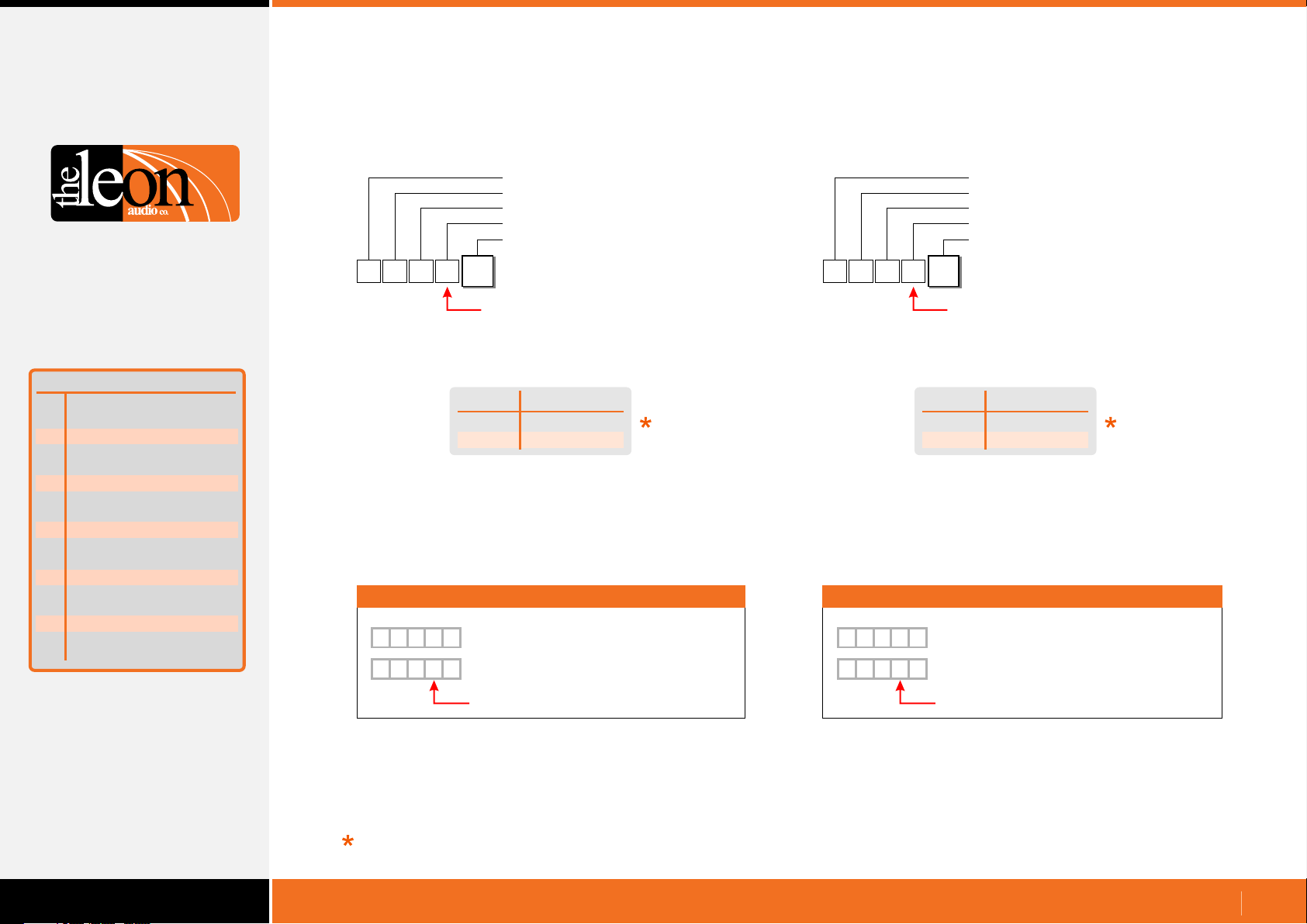
Standby Dims on Acknowledge
•
Configuration Header
Master number (0-6)
Channel number (0-16)
Standby Dims on Acknowledge
Value
{
Either a letter or a number can be used for the ASCII Value.
Use which ever you prefer. Letters are not case sensitive.
5
1
{
1
{
1
E
1
Function is Upper Case
Value
0 or N
1 or D
5
E
0
Master 1, Ch5, S/by does not Dim on Ack.
5
E
D
Master 1, Ch5, S/by Dims on Acknowledge
Function is Upper Case
Standby Flash
No Dim on Ack
Dim on Ack
Outstation Go Flickers
•
Configuration Header
Master number (0-6)
Channel number (0-16)
Outstation Go Flickers
Value
{
Either a letter or a number can be used for the ASCII Value.
Use which ever you prefer. Letters are not case sensitive.
5
1
F
1
Function is Upper Case
Value
0 or S
1 or F
Go Flickers
Steady
Flickers
ExamplesExamples
{
5
1
{
1
0
F
Master 1, Ch5, Outstation Go doesn’t Flicker
5
F
F
Master 1, Ch5, Outstation Go Flickers
Function is Upper Case
Factory default
www.LeonAudio.com.au
33.
Page 34
Configuration Commands
Cue Light Outstation Functions
Function
Outstation
A
S/by Flash on Master
B
S/by Flash on Outstation
C
S/by latches
D
S/by Dims on ACK
E
F
Outstation Go Flickers
G
Go times out
H
Go flashes
J
Go latches
K
Go & S/by interlocked
M
Call lamp enabled
N
Call lamp flashes
P
ACK button back-light
Q
Beeper enable
R
Beep-on-Go
S
Change colour on ACK
T
Dimmer
S/by colour
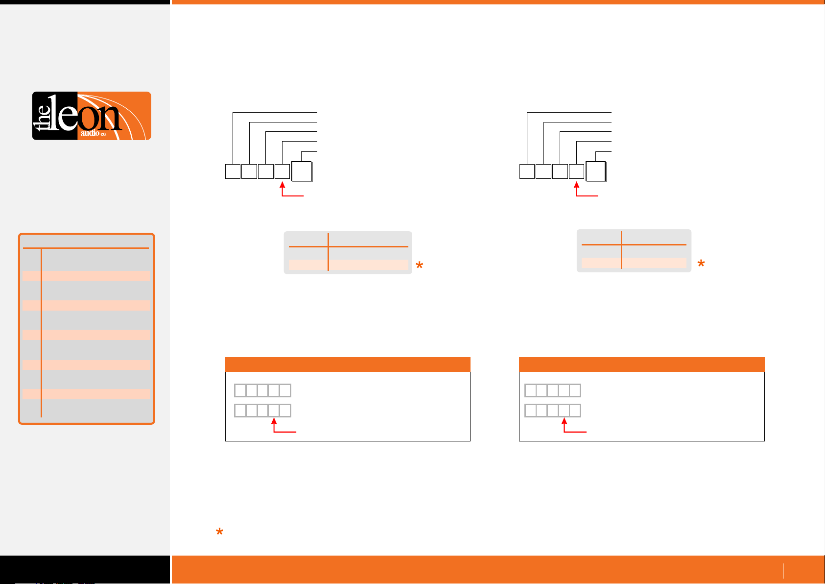
Go times out
•
Configuration Header
Master number (0-6)
Channel number (0-16)
Go times out
Value
{
Either a letter or a number can be used for the ASCII Value.
Use which ever you prefer. Letters are not case sensitive.
The Factory Default time out period is 15 seconds.
This time can be adjusted from 1 to 16 seconds. See page 58
5
1
G
1
Function is Upper Case
Value
0 or N
1 or T
Does Not Time Out
Times Out
Go time out
Examples
{
5
G
1
{
1
0
Master 1, Ch5, Go does not time out.
5
G
T
Master 1, Ch5, Go times out
Go Flashes after 3 seconds
•
Configuration Header
Master number (0-6)
Channel number (0-16)
Go Flashes after 3 seconds
Value
{
Either a letter or a number can be used for the ASCII Value.
Use which ever you prefer. Letters are not case sensitive.
5
1
H
1
Function is Upper Case
Value
0 or S
1 or F
Go Flashes
Steady
Flashes
Examples
{
5
1
{
1
0
H
Master 1, Ch5, Outstation Go doesn’t Flash
5
H
F
Master 1, Ch5, Outstation Go Flashes
Summary of Cue Light
Outstation Functions
Factory default
Function is Upper Case
Function is Upper Case
www.LeonAudio.com.au
34.
Page 35
Configuration Commands
Cue Light Outstation Functions
Function
Outstation
A
S/by Flash on Master
B
S/by Flash on Outstation
C
S/by latches
D
S/by Dims on ACK
E
F
Outstation Go Flickers
G
Go times out
H
Go flashes
J
Go latches
K
Go & S/by interlocked
M
Call lamp enabled
N
Call lamp flashes
P
ACK button back-light
Q
Beeper enable
R
Beep-on-Go
S
Change colour on ACK
T
Dimmer
S/by colour
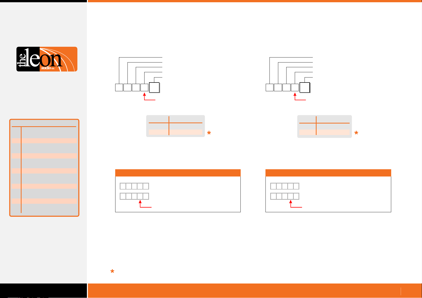
Go latches
•
Configuration Header
Master number (0-6)
Channel number (0-16)
Go latches
Value
{
Either a letter or a number can be used for the ASCII Value.
Use which ever you prefer. Letters are not case sensitive.
5
1
J
1
Function is Upper Case
Value
0 or M
1 or L
Go atchL
Momentary
Latches
Examples
{
5
J
1
{
1
0
Master 1, Ch5, Go momentary action
5
J
L
Master 1, Ch5, Go latching action
Function is Upper Case
Go & Standby interlocked
•
{
5
1
K
1
Function is Upper Case
Value
0
1
Examples
{
5
1
{
1
0
K
Master 1, Ch5, Go & S/by Independant
5
K
1
Master 1, Ch5, Go & S/by Interlocked
Function is Upper Case
Configuration Header
Master number (0-6)
Channel number (0-16)
Go & Standby interlocked
Value
Interlocked
Independant
Interlocked
Summary of Cue Light
Outstation Functions
Factory default
www.LeonAudio.com.au
35.
Page 36
Configuration Commands
Cue Light Outstation Functions
Function
Outstation
A
S/by Flash on Master
B
S/by Flash on Outstation
C
S/by latches
D
S/by Dims on ACK
E
F
Outstation Go Flickers
G
Go times out
H
Go flashes
J
Go latches
K
Go & S/by interlocked
M
Call enabled
N
Call lamp flashes
P
ACK button back-light
Q
Beeper enable
R
Beep-on-Go
S
Change colour on ACK
T
Dimmer
Summary of Cue Light
Outstation Functions
S/by colour
lamp
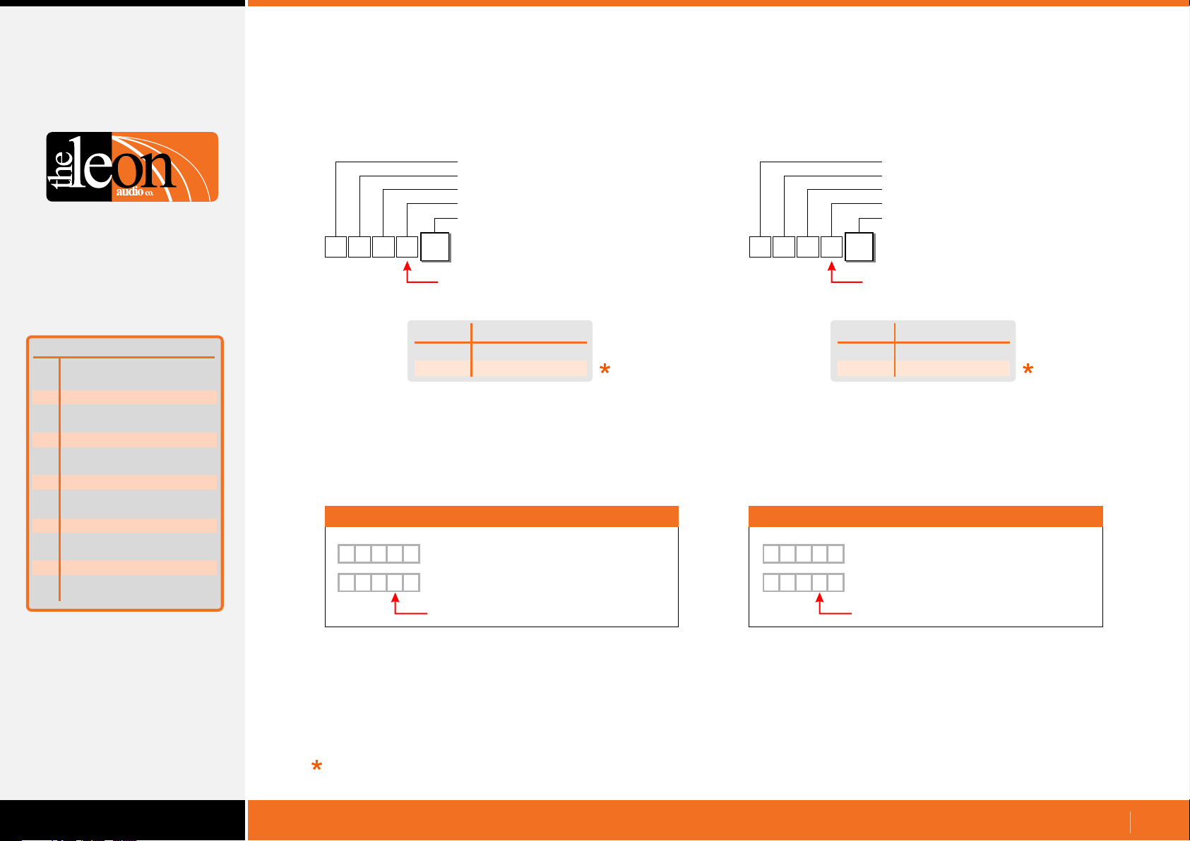
Call lamp enabled
•
Configuration Header
Master number (0-6)
Channel number (0-16)
Call lamp enabled
Value
{
Either a letter or a number can be used for the ASCII Value.
Use which ever you prefer. Letters are not case sensitive.
5
1
M
1
Function is Upper Case
Value
0 or D
1 or E
Call lamp enabled
Disabled
Enabled
Examples
{
5
M
1
{
1
0
Master 1, Ch5, Call lamp disabled
5
M
E
Master 1, Ch5, call lamp enabled
Function is Upper Case
Call lamp flashes
•
Configuration Header
Master number (0-6)
Channel number (0-16)
Call lamp flashes
Value
{
Either a letter or a number can be used for the ASCII Value.
Use which ever you prefer. Letters are not case sensitive.
5
1
N
1
Function is Upper Case
Value
0 or S
1 or F
Call lamp flashes
Steady
Flashes
Examples
{
5
N
1
{
1
0
Master 1, Ch5, Call lamp steady
5
N
F
Master 1, Ch5, Call lamp flashes
Function is Upper Case
Factory default
www.LeonAudio.com.au
36.
Page 37
Configuration Commands
Cue Light Outstation Functions
Function
Outstation
A
S/by Flash on Master
B
S/by Flash on Outstation
C
S/by latches
D
S/by Dims on ACK
E
F
Outstation Go Flickers
G
Go times out
H
Go flashes
J
Go latches
K
Go & S/by interlocked
M
Call lamp enabled
N
Call lamp flashes
P
ACK button back-light
Q
Beeper enable
R
Beep-on-Go
S
Change colour on ACK
T
Dimmer
Summary of Cue Light
Outstation Functions
S/by colour
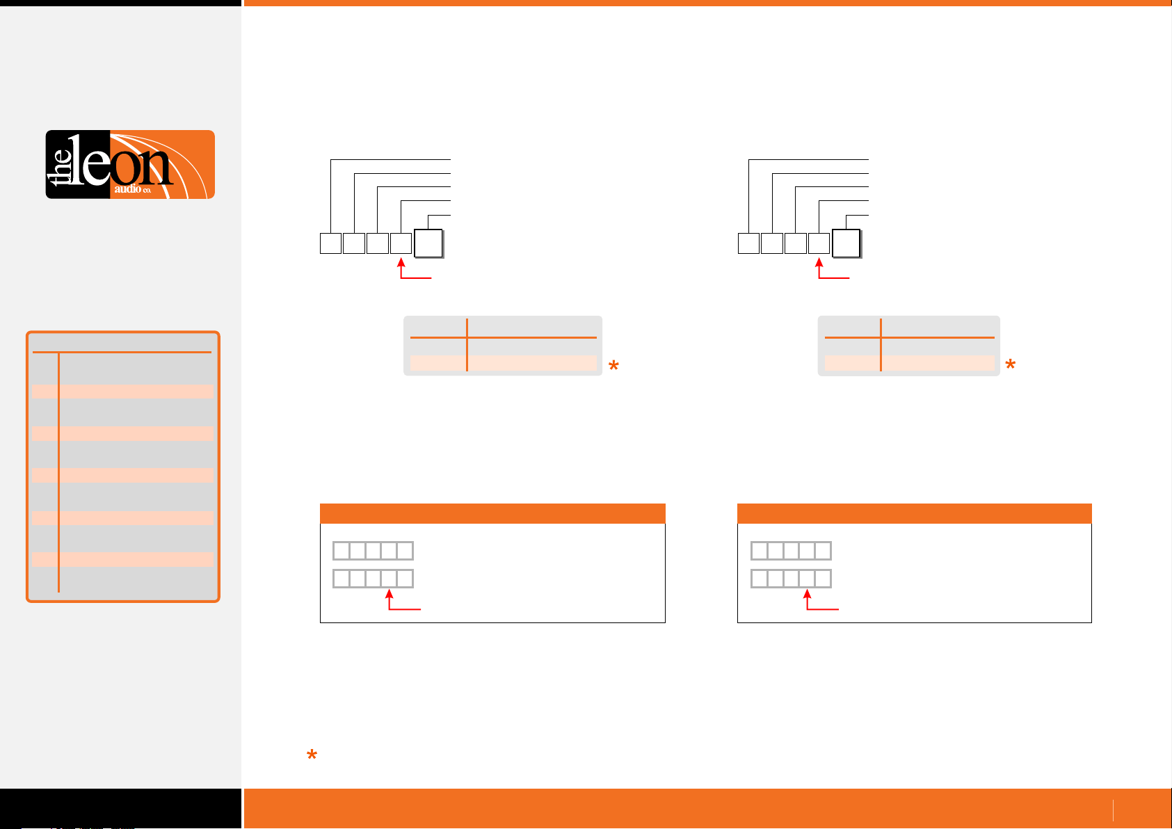
Acknowledge button back-light
•
Configuration Header
Master number (0-6)
Channel number (0-16)
ACK button back-light
Value
{
Either a letter or a number can be used for the ASCII Value.
Use which ever you prefer. Letters are not case sensitive.
5
1
P
1
Function is Upper Case
Value
0 or F
1 or N
ACK button back-light
Off
On
Examples
{
5
P
1
{
1
0
Master 1, Ch5, ACK button back-light off
5
P
N
Master 1, Ch5, ACK button back-light on
Function is Upper Case
Beeper enable
•
Configuration Header
Master number (0-6)
Channel number (0-16)
Beeper enable
Value
{
Either a letter or a number can be used for the ASCII Value.
Use which ever you prefer. Letters are not case sensitive.
5
1
Q
1
Function is Upper Case
Value
0 or F
1 or N
Beeper enable
Off
On (enabled)
Examples
{
{
Q
5
1
1
0
Master 1, Ch5, Beeper off (disabled)
Q
5
N
Master 1, Ch5, Beeper on (enabled)
Function is Upper Case
Factory default
www.LeonAudio.com.au
37.
Page 38
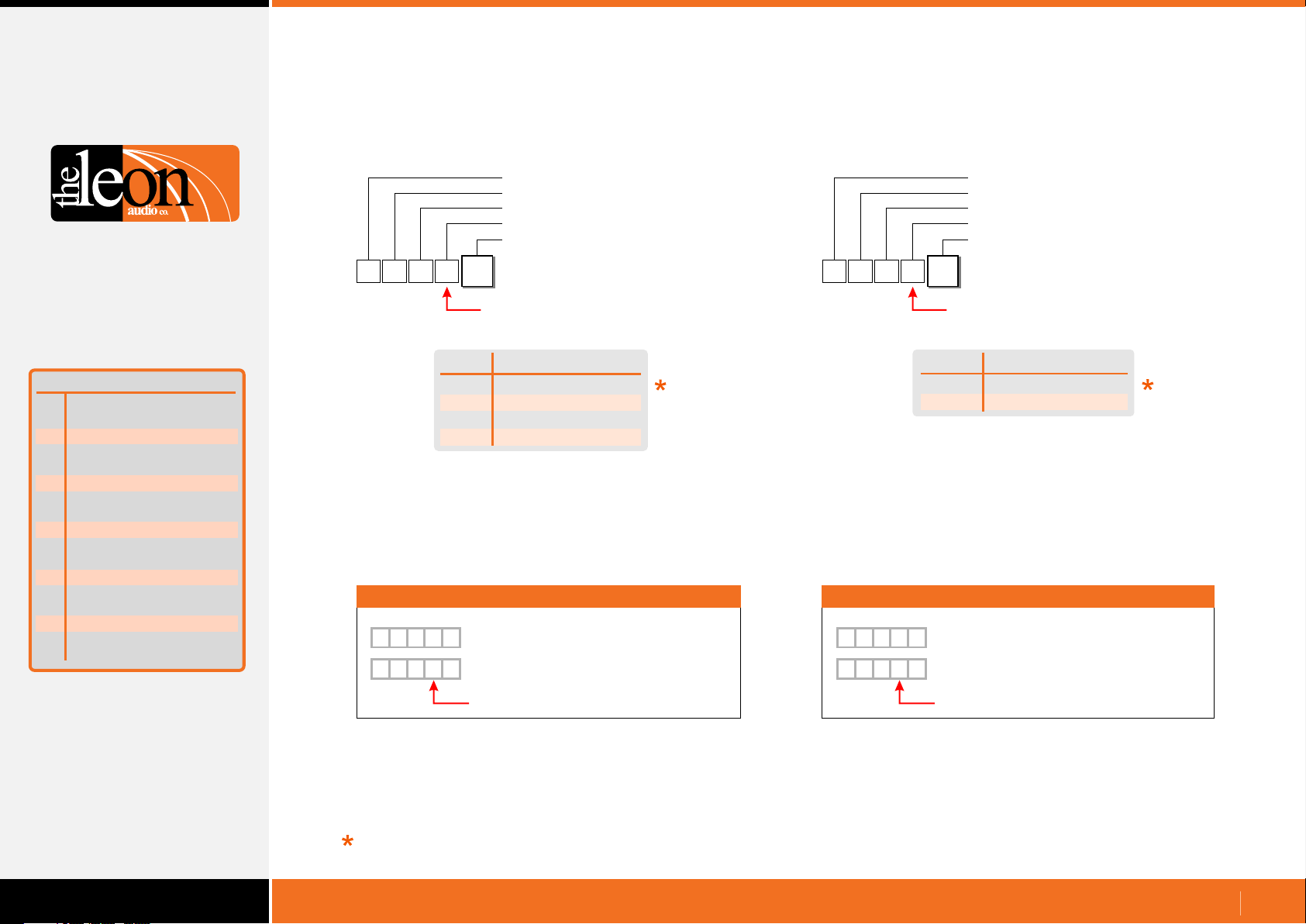
Configuration Commands
Cue Light Outstation Functions
Function
Outstation
A
S/by Flash on Master
B
S/by Flash on Outstation
C
S/by latches
D
S/by Dims on ACK
E
F
Outstation Go Flickers
G
Go times out
H
Go flashes
J
Go latches
K
Go & S/by interlocked
M
Call lamp enabled
N
Call lamp flashes
P
ACK button back-light
Q
Beeper enable
R
Beep-on-Go
S
Change colour on ACK
T
Dimmer
Summary of Cue Light
Outstation Functions
S/by colour
Beep-on-Go
•
Configuration Header
Master number (0-6)
Channel number (0-16)
Beep-on-Go
Value
{
Note 1
A beep of 1mS duration is so short that it is heard as a click.
5
1
R
1
Function is Upper Case
Value
Beep-on-Go duration
0
1
2
3
Off
1mS Note 1
50mS
200mS
Examples
{
5
R
1
{
1
0
Master 1, Ch5, Beep-on-Go off
5
R
2
Master 1, Ch5, Beep-on-Go 50mS
Function is Upper Case
Change colour on Acknowledge
•
Configuration Header
Master number (0-6)
Channel number (0-16)
Change colour on Acknowledge
Value
{
Either a letter or a number can be used for the ASCII Value.
Use which ever you prefer. Letters are not case sensitive.
5
1
S
1
Function is Upper Case
Value
0 or N
1 or C
Change colour on ACK
No colour change
Change colour
Examples
{
5
S
1
{
1
0
Master 1, Ch5, No colour change on ACK
5
S
C
Master 1, Ch5, Change colour on ACK
Function is Upper Case
Factory default
www.LeonAudio.com.au
38.
Page 39
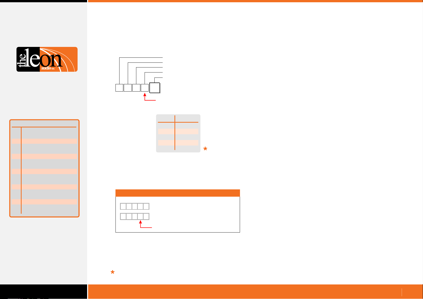
Configuration Commands
Cue Light Outstation Functions
Dimmer
•
Configuration Header
Master number (0-6)
Channel number (0-16)
Dimmer
Value
Function
Outstation
A
S/by Flash on Master
B
S/by Flash on Outstation
C
S/by latches
D
S/by Dims on ACK
E
F
Outstation Go Flickers
G
Go times out
H
Go flashes
J
Go latches
K
Go & S/by interlocked
M
Call lamp enabled
N
Call lamp flashes
P
ACK button back-light
Q
Beeper enable
R
Beep-on-Go
S
Change colour on ACK
T
Dimmer
Summary of Cue Light
Outstation Functions
S/by colour
{
5
1
Examples
{
5
1
{
5
1
T
1
Function is Upper Case
Value
1
2
3
4
5
T
5
Master 1, Ch5,
T
2
Master 1, Ch5,
Function is Upper Case
Dimmer
5%
25%
50%
75%
100%
Dimmer 100%
Dimmer 25%
Factory default
www.LeonAudio.com.au
39.
Page 40
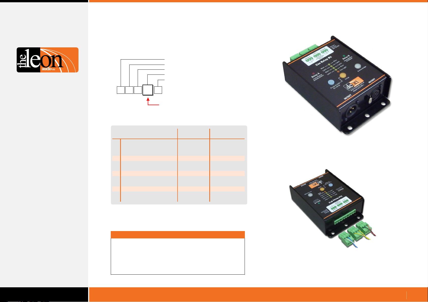
Configuration Commands
Relay Outstation Functions
Configuration Header
Master number (0-6)
Channel number (0-9, A-G)
Function
Value (depends on function)
b
Function
a
Mode
b
S/by Flash on Master
c
S/by Flash on Outstation
d
S/by latches
e
Go times out
f
Go flashes
g
Go latches
h
Go & S/by interlocked
j
Call lamp enabled
k
Call lamp Flashes
m
All Lamps on Outstation
Summary of Relay Outstation Functions
Relay Outstation Functions
For Relay Outstations,
Function is Lower Case
Factory
Default
Flashes
Flashes
Latches
Times out
Flashes
Latches
Interlocked
Enabled
Flashes
Enabled
User Selectable
Function
5 modes
Steady
Steady
Momentary
Stays on
Steady
Momentary
Independent
Call lamp off
Steady
Off
Important
All commands must be followed by the letter X for eXecute.
Once X has been received by the PCinterface, the
commands are uploaded to the Master Station(s).
Multiple commands may be entered followed by a single X.
Relay Outstation QLR Mk4
Relay A
Acknowledge Button
Relay B
Relay Outstation Rear
www.LeonAudio.com.au
40.
Page 41
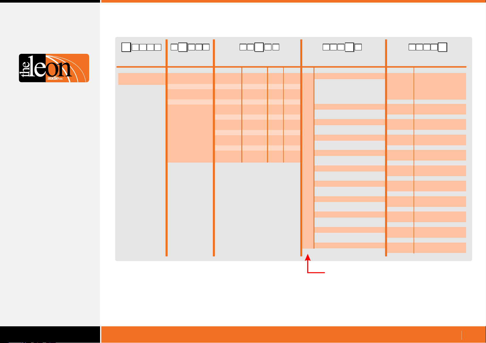
Table of Relay Outstation Configuration Commands
b
1 15
{
Configuration
Commands
Header Byte
(Left curly bracket)
{
1
15 b 1{b1
5 b 1
Master
number Channel number
ASCII Dec Hex Description Description
0 (Global)
1
2
3
4
5
6
0 (Global)
1
2
3
4
5
6
7
8
9
10
11
12
13
14
15
16
0
1
2
3
4
5
6
7
8
9
A or (10)
B or (11)
C or (12)
D or (13)
E or (14)
F or (15)
G or (16)
Note 1
00d
01d
02d
03d
04d
05d
06d
07d
08d
09d
10d
11d
12d
13d
14d
15d
16d
Note 2
00h
01h
02h
03h
04h
05h
06h
07h
08h
09h
0Ah
0Bh
0Ch
0Dh
0Eh
0Fh
10h
{
Function
Mode
a
S/by Flash on Master
b
S/by Flash on Outstation
c
S/by latches
d
Go times out
e
Go flashes
f
Go latches
g
Go & S/by interlocked
h
151
{
b51
Value
1
2
3
4
5
0 or S
1 or F
0 or S
1 or F
0 or M
1 or L
0 or N
1 or T
0 or S
1 or F
0 or M
1 or L
0
1
A: Mom B: Mom
A: Latch B: Latch
A: Mom B: Latch
A: Latch B: Mom
Cue Light Mode
Steady
Flashes
Steady
Flashes
Momentary
Latches
No time-out
Times-out after delay
Steady
Flashes after 3 secs.
Momentary
Latches
Independant
Interlocked
Note 1:
Note 2: Channel number can be ASCII characters or a decimal number 00d to 16d.
Double digits can be in round brackets e.g. (12)
Multiple channels in round brackets e.g. (1,2,3) or (5-15)
Call lamp enabled
j
Call lamp Flashes
k
All Lamps on Outstation
m
This Column is Lower Case
0 or D
1 or E
0 or S
1 or F
0 or D
1 or E
Disabled
Enabled
Steady
Flashes
Disabled
Enabled
www.LeonAudio.com.au
41.
Page 42
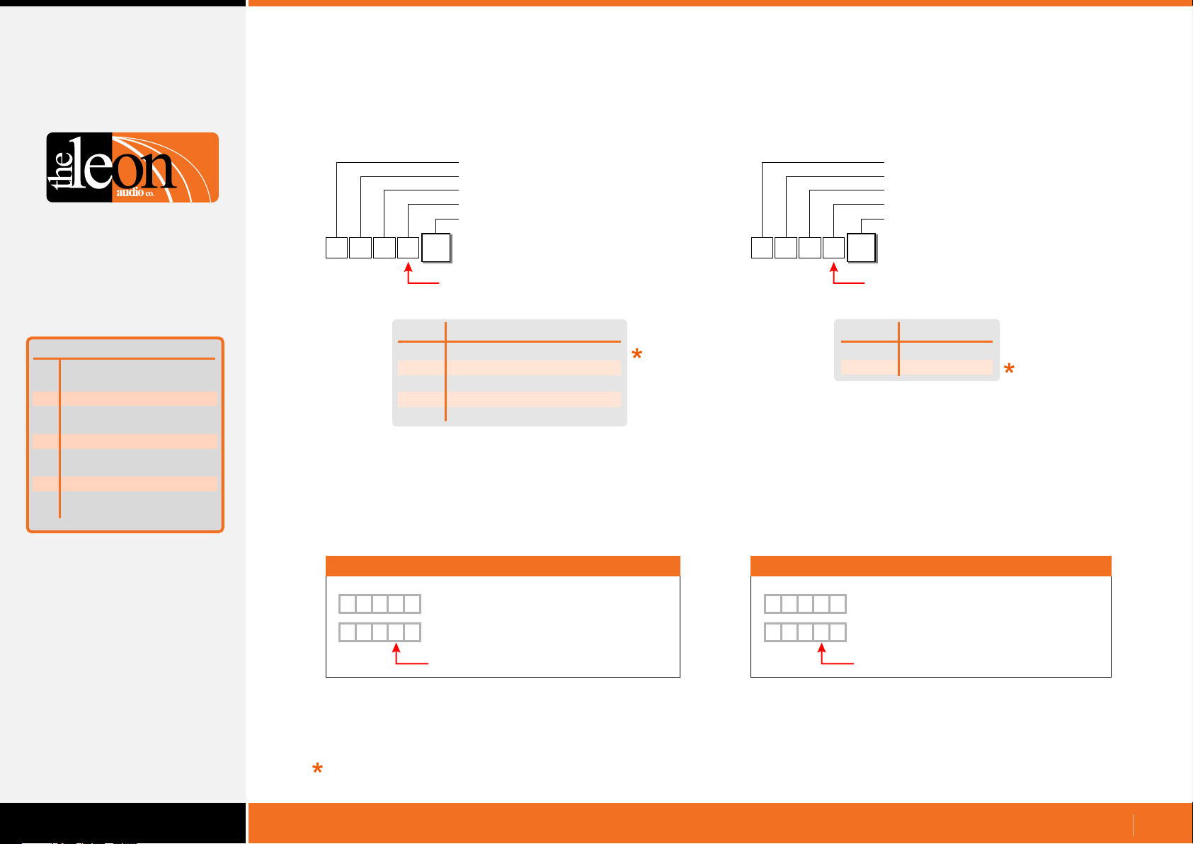
Configuration Commands
Relay Outstation Functions
Function
Mode
a
S/by Flash on Master
b
S/by Flash on Outstation
c
S/by latches
d
Go times out
e
Go flashes
f
Go latches
g
Go & S/by interlocked
h
Call lamp enabled
j
Call lamp Flashes
k
All Lamps on Outstation
m
Mode
•
Configuration Header
Master number (0-6)
Channel number (0-16)
Mode
Value
{
Relay A: controlled by the Standby button.
Relay B: controlled by the Go button.
When Cue Light mode is selected, the settings stored in
Functions c to k are used.
5
1
a
1
Function is Lower Case
Value
A: Momentary B: Momentary
1
2
A: Latch B: Latch
3
A: Momentary B: Latch
4
A: Latch B: Momentary
5
Cue Light Mode
Mode
Standby Lamp Flash on Master
•
Configuration Header
Master number (0-6)
Channel number (0-16)
Standby Lamp Flash on Master
Value
{
Either a letter or a number can be used for the ASCII Value.
Use which ever you prefer. Letters are not case sensitive.
5
1
b
1
Function is Lower Case
Value
0 or S
1 or F
Standby Flash
Steady
Flashes
Summary of Relay
Outstation Functions
Examples
{
5
a
1
{
5
a
1
Factory default
2
Master 1, Ch5, Mode 2: A: Latch B: Latch
5
Master 1, Ch5, Mode 5: Cue Light Mode
Function is Lower Case
Examples
{
5
1
{
5
1
b
0
Master 1, Ch5, S/by steady on Master
b
F
Master 1, Ch5, S/by flashes on Master
Function is Lower Case
www.LeonAudio.com.au
42.
Page 43
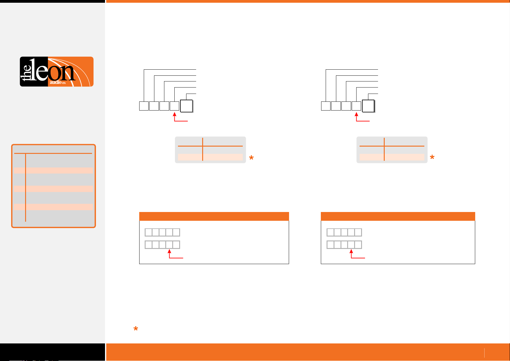
Configuration Commands
Relay Outstation Functions
Function
Mode
a
S/by Flash on Master
b
S/by Flash on Outstation
c
S/by latches
d
Go times out
e
Go flashes
f
Go latches
g
Go & S/by interlocked
h
Call lamp enabled
j
Call lamp Flashes
k
All Lamps on Outstation
m
Standby Lamp Flash on Outstation
•
Configuration Header
Master number (0-6)
Channel number (0-16)
Standby Lamp Flash on Outstation
Value
{
1
Either a letter or a number can be used for the ASCII Value.
Use which ever you prefer. Letters are not case sensitive.
c
5
1
Function is Lower Case
Value
0 or S
1 or F
Standby Flash
Steady
Flashes
Examples
S/by latches
•
Configuration Header
Master number (0-6)
Channel number (0-16)
S/by latches
Value
{
Either a letter or a number can be used for the ASCII Value.
Use which ever you prefer. Letters are not case sensitive.
5
1
d
1
Function is Lower Case
Value
0 or M
1 or L
Standby Latch
Momentary
Latches
Examples
Summary of Relay
Outstation Functions
{
5
c
1
{
5
c
1
Factory default
0
Master 1, Ch5, S/by steady on Outstation
F
Master 1, Ch5, S/by flashes on Outstation
Function is Lower Case
{
5
1
{
1
0
d
Master 1, Ch5, S/by momentary action
5
d
L
Master 1, Ch5, S/by latching action
Function is Lower Case
www.LeonAudio.com.au
43.
Page 44
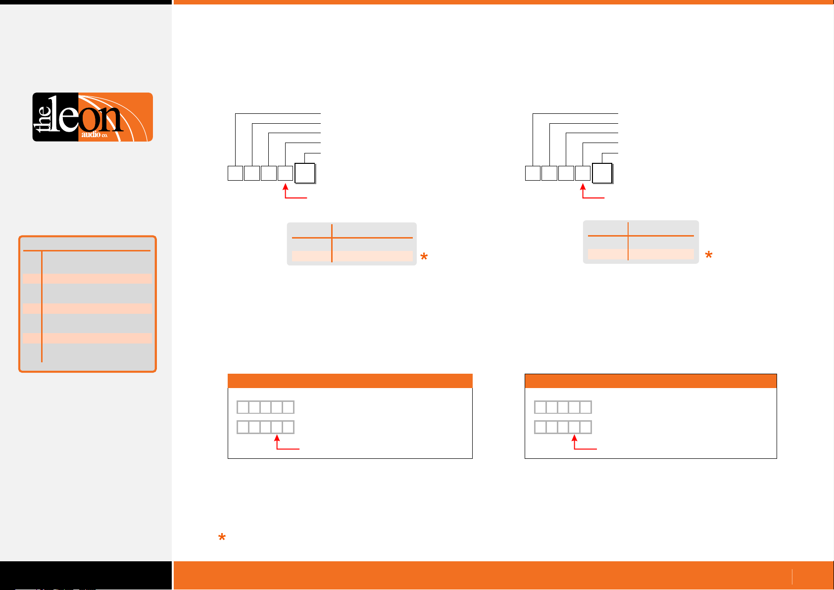
Configuration Commands
Relay Outstation Functions
Function
Mode
a
S/by Flash on Master
b
S/by Flash on Outstation
c
S/by latches
d
Go times out
e
Go flashes
f
Go latches
g
Go & S/by interlocked
h
Call lamp enabled
j
Call lamp Flashes
k
All Lamps on Outstation
m
Go times out
•
Configuration Header
Master number (0-6)
Channel number (0-16)
Go times out
Value
{
Either a letter or a number can be used for the ASCII Value.
Use which ever you prefer. Letters are not case sensitive.
The Factory Default time out period is 15 seconds.
This time can be adjusted from 1 to 16 seconds. See page 58
5
1
e
1
Function is Lower Case
Value
0 or N
1 or T
Does Not Time Out
Times Out
Go time out
Go Flashes after 3 seconds
•
Configuration Header
Master number (0-6)
Channel number (0-16)
Go Flashes after 3 seconds
Value
{
Either a letter or a number can be used for the ASCII Value.
Use which ever you prefer. Letters are not case sensitive.
5
1
f
1
Function is Lower Case
Value
0 or S
1 or F
Go Flashes
Steady
Flashes
Summary of Relay
Outstation Functions
Examples Examples
{
5
e
1
{
5
e
1
Factory default
0
Master 1, Ch5, Go does not time out.
T
Master 1, Ch5, Go times out
Function is Lower Case Function is Lower Case
{
1
{
1
5
0
f
Master 1, Ch5, Outstation Go doesn’t Flash
5
f
F
Master 1, Ch5, Outstation Go Flashes
www.LeonAudio.com.au
44.
Page 45
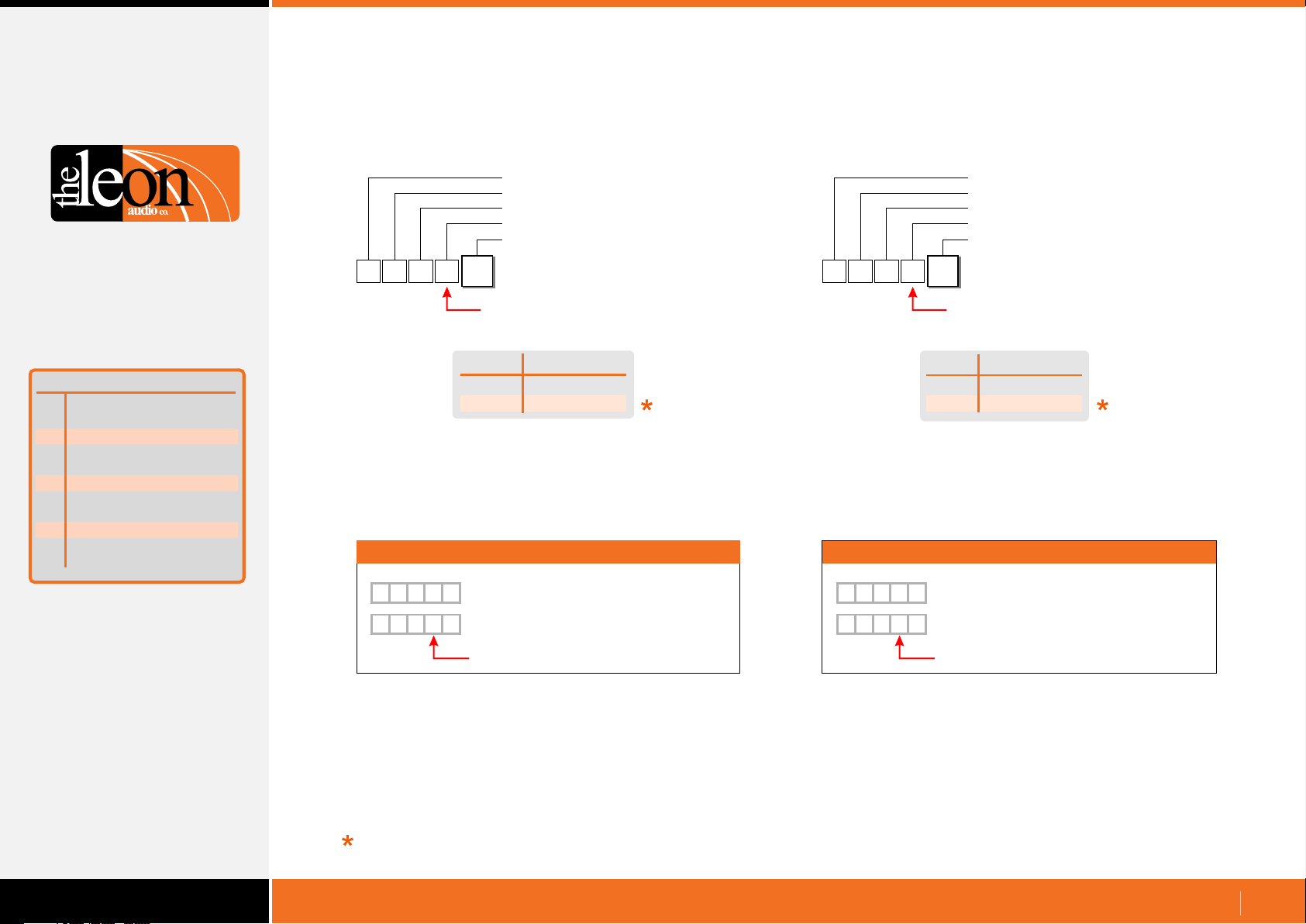
Configuration Commands
Relay Outstation Functions
Function
Mode
a
S/by Flash on Master
b
S/by Flash on Outstation
c
S/by latches
d
Go times out
e
Go flashes
f
Go latches
g
Go & S/by interlocked
h
Call lamp enabled
j
Call lamp Flashes
k
All Lamps on Outstation
m
Go latches
•
Configuration Header
Master number (0-6)
Channel number (0-16)
Go latches
Value
{
1
Either a letter or a number can be used for the ASCII Value.
Use which ever you prefer. Letters are not case sensitive.
g
5
1
Function is Lower Case
Value
0 or M
1 or L
Go atchL
Momentary
Latches
Examples
Go & Standby interlocked
•
{
5
1
h
1
Function is Lower Case
Value
0
1
Examples
Configuration Header
Master number (0-6)
Channel number (0-16)
Go & Standby interlocked
Value
Interlocked
Independant
Interlocked
Summary of Relay
Outstation Functions
{
{
Factory default
g
5
1
g
5
1
{
5
0
Master 1, Ch5, Go momentary action
L
Master 1, Ch5, Go latching action
Function is Lower Case Function is Lower Case
1
{
1
0
h
Master 1, Ch5, Go & S/by Independant
5
h
1
Master 1, Ch5, Go & S/by Interlocked
www.LeonAudio.com.au
45.
Page 46
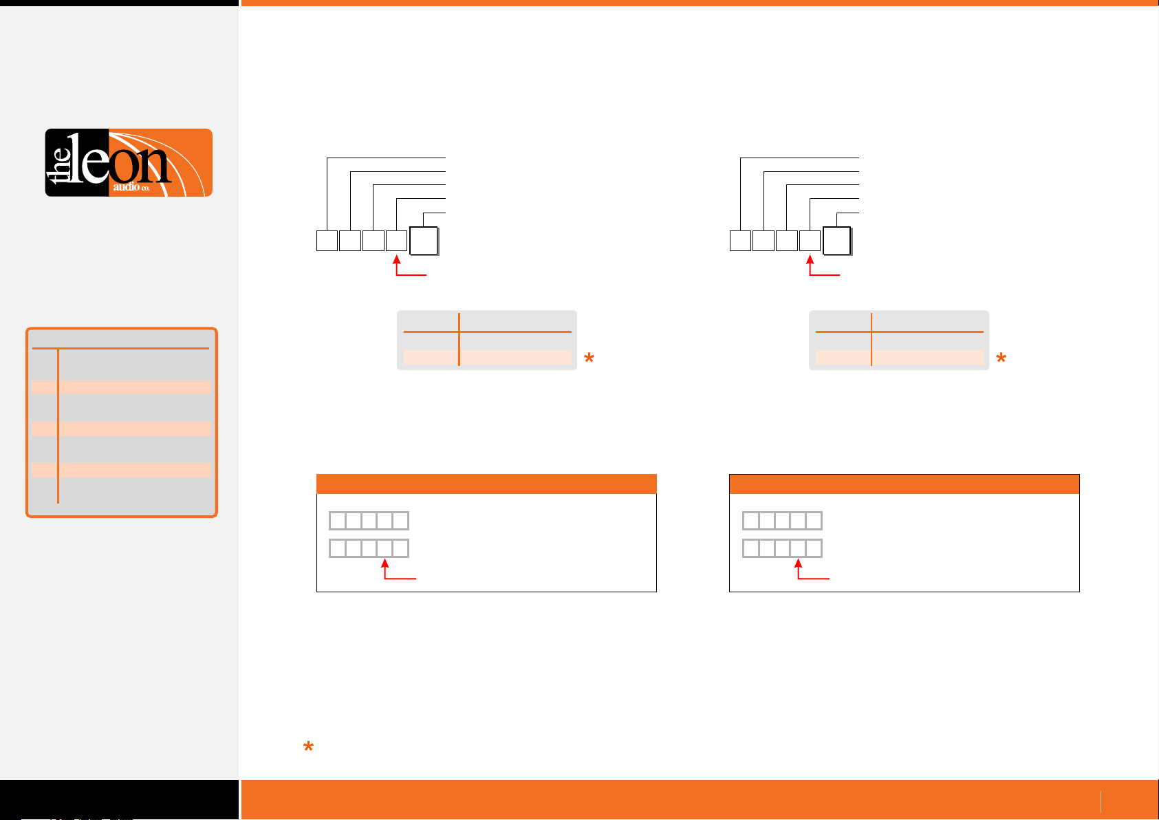
Configuration Commands
Relay Outstation Functions
Function
Mode
a
S/by Flash on Master
b
S/by Flash on Outstation
c
S/by latches
d
Go times out
e
Go flashes
f
Go latches
g
Go & S/by interlocked
h
Call lamp enabled
j
Call lamp Flashes
k
All Lamps on Outstation
m
Summary of Relay
Outstation Functions
Call lamp enabled
•
Configuration Header
Master number (0-6)
Channel number (0-16)
Call lamp enabled
Value
{
1
Either a letter or a number can be used for the ASCII Value.
Use which ever you prefer. Letters are not case sensitive.
j
5
1
Function is Lower Case
Value
0 or D
1 or E
Call lamp enabled
Disabled
Enabled
Examples
{
{
j
5
1
1
0
Master 1, Ch5, Call lamp disabled
j
5
E
Master 1, Ch5, call lamp enabled
Call lamp flashes
•
Configuration Header
Master number (0-6)
Channel number (0-16)
Call lamp flashes
Value
{
Either a letter or a number can be used for the ASCII Value.
Use which ever you prefer. Letters are not case sensitive.
5
1
k
1
Function is Lower Case
Value
0 or S
1 or F
Call lamp flashes
Steady
Flashes
Examples
{
5
k
1
{
1
0
Master 1, Ch5, Call lamp steady
5
k
F
Master 1, Ch5, Call lamp flashes
Factory default
Function is Lower Case Function is Lower Case
www.LeonAudio.com.au
46.
Page 47
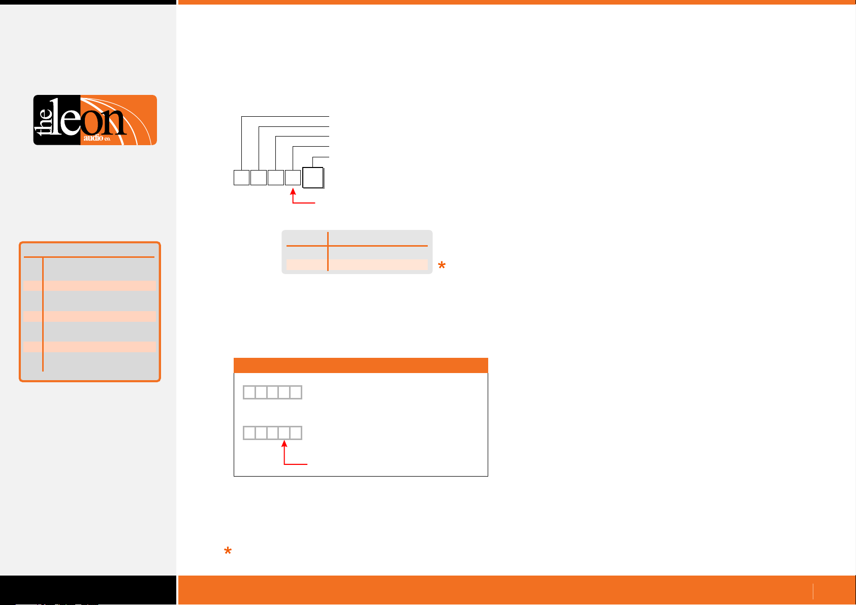
Configuration Commands
Relay Outstation Functions
All Lamps on Outstation
•
Configuration Header
Master number (0-6)
Channel number (0-16)
All Lamps on Outstation
Value
Function
Mode
a
S/by Flash on Master
b
S/by Flash on Outstation
c
S/by latches
d
Go times out
e
Go flashes
f
Go latches
g
Go & S/by interlocked
h
Call lamp enabled
j
Call lamp Flashes
k
All Lamps on Outstation
m
Summary of Relay
Outstation Functions
{
Either a letter or a number can be used for the ASCII Value.
Use which ever you prefer. Letters are not case sensitive.
5
1
m
1
Function is Lower Case
Value
0 or D
1 or E
All Lamps on Outstation
Disabled (off)
Enabled
Examples
{
5
m
1
{
1
0
Master 1, Ch5,
All Lamps on Outstation disabled
5
m
E
Master 1, Ch5,
All Lamps on Outstation enabled
Function is Lower Case
Factory default
www.LeonAudio.com.au
47.
Page 48
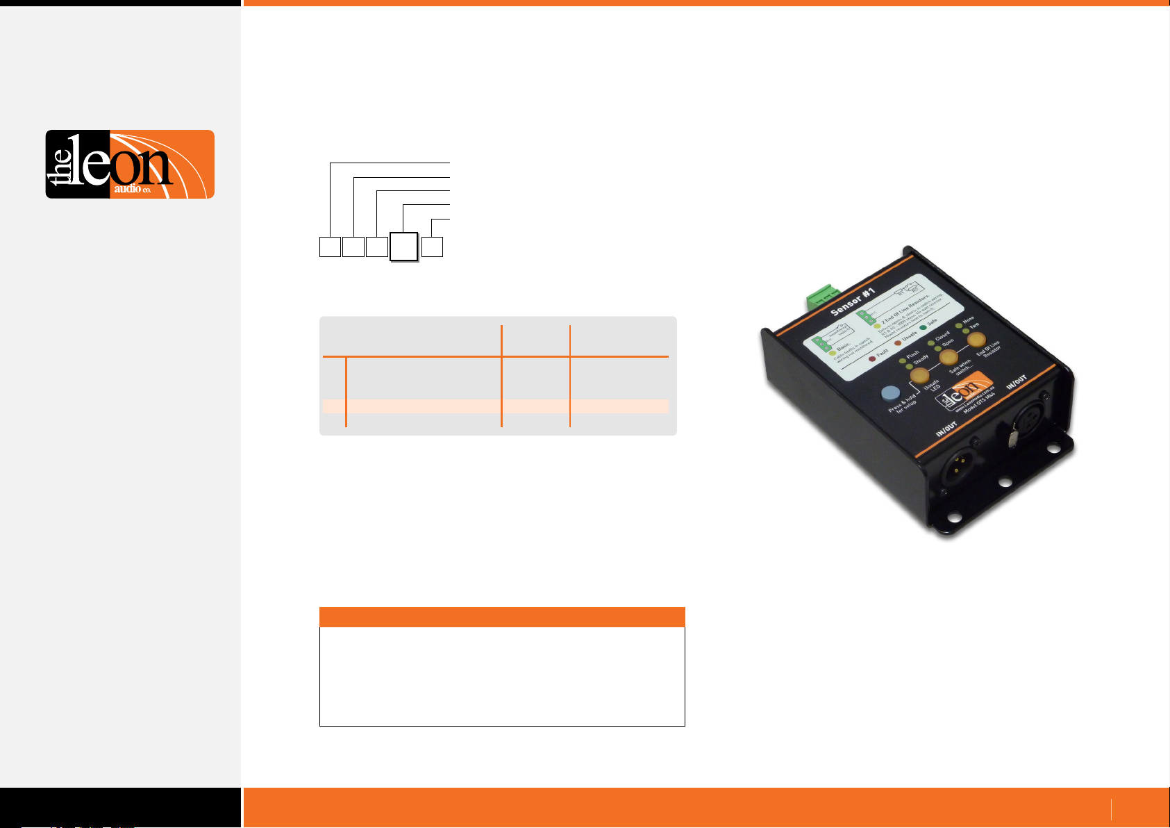
Configuration Commands
Sensor Outstation Functions
Configuration Header
Master number (0-6)
Channel number (0-9, A-G)
Function
Value (depends on function)
{
Summary of Sensor Outstation Functions
5
1
Function
1
Unsafe Lamp
2
Safe when... open/closed
3
End Of Line Resistors
4
All Lamps on Outstation
1
Sensor Outstation Functions
0
Factory
Default
Steady
Open
No EOL
Enabled
Important
User Selectable
Function
Flash
Closed
Two EOL
Disabled
Sensor Outstation QTS Mk4
All commands must be followed by the letter X for eXecute.
Once X has been received by the PCinterface, the
commands are uploaded to the Master Station(s).
Multiple commands may be entered followed by a single X.
www.LeonAudio.com.au
48.
Page 49
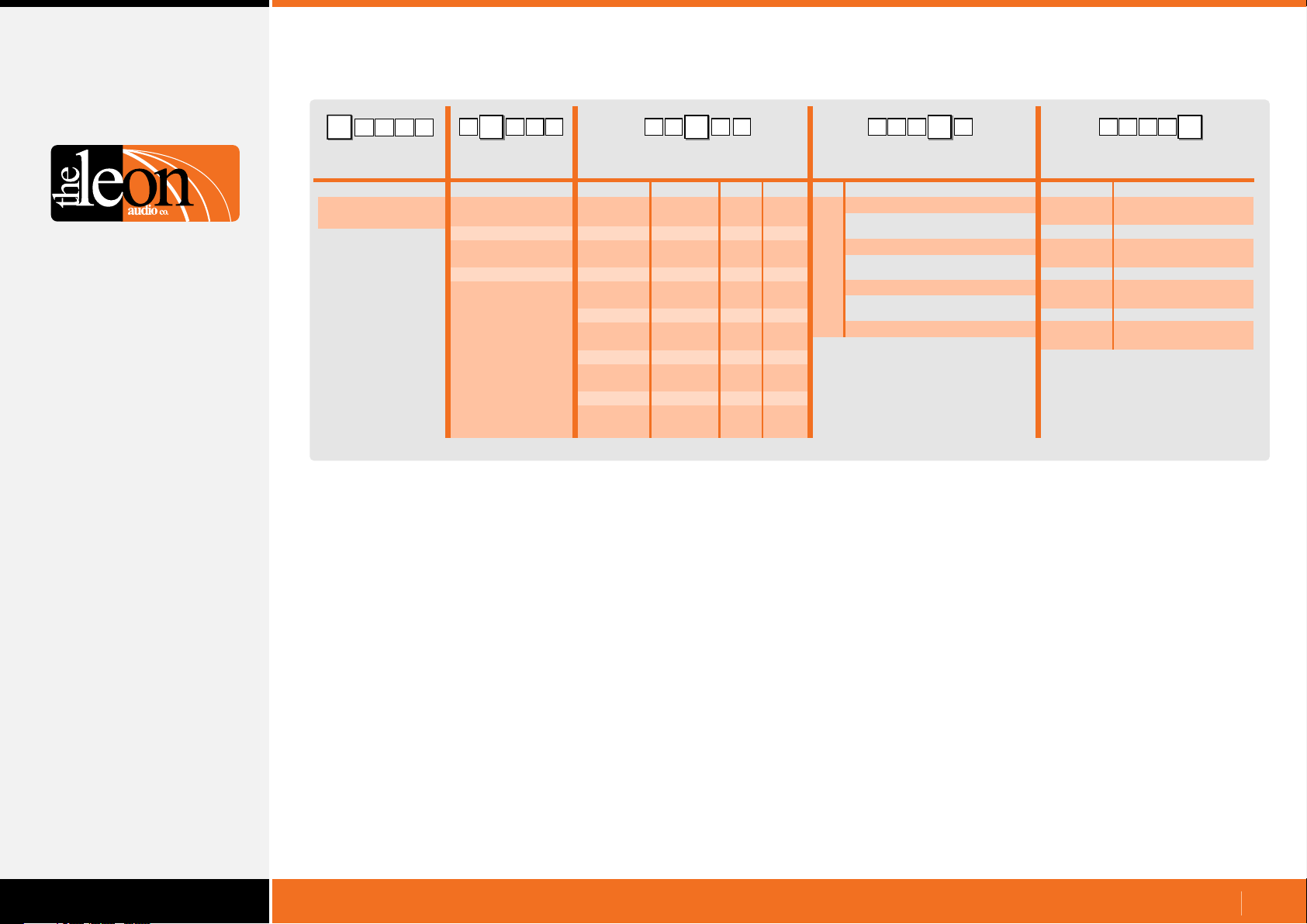
Table of Sensor Outstation Configuration Commands
3
1 15
{
Configuration
Commands
Header Byte
(Left curly bracket)
Note 1:
Note 2: Channel number can be ASCII characters or a decimal number 00d to 16d.
Double digits can be in round brackets e.g. (12)
Multiple channels in round brackets e.g. (1,2,3) or (5-15)
{
1
15 3
5 3 1
Master
number Channel number
ASCII Dec Hex Description Description
0 (Global)
1
2
3
4
5
6
0 (Global)
1
2
3
4
5
6
7
8
9
10
11
12
13
14
15
16
0
1
2
3
4
5
6
7
8
9
A or (10)
B or (11)
C or (12)
D or (13)
E or (14)
F or (15)
G or (16)
Note 1
1{31
00d
01d
02d
03d
04d
05d
06d
07d
08d
09d
10d
11d
12d
13d
14d
15d
16d
Note 2
00h
01h
02h
03h
04h
05h
06h
07h
08h
09h
0Ah
0Bh
0Ch
0Dh
0Eh
0Fh
10h
{
Function
Unsafe Lamp
1
Safe when... open/closed
2
End Of Line Resistors
3
4
All Lamps on Outstation
151
{
351
Value
0 or S
1 or F
0 or O
1 or C
0 or N
1 or T
0 or D
1 or E
Steady
Flashes
Open
Closed
No EOL
two EOL
Disabled
Enabled
www.LeonAudio.com.au
49.
Page 50
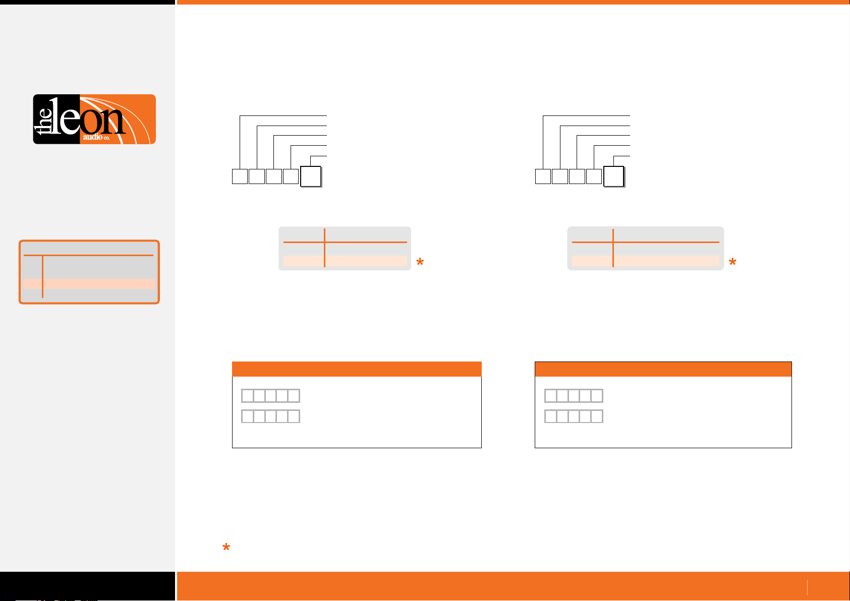
Configuration Commands
Sensor Outstation Functions
Function
Unsafe Lamp
1
Safe when... open/closed
2
End Of Line Resistors
3
All Lamps on Outstation
4
Summary of Sensor
Outstation Functions
Unsafe Lamp
•
Configuration Header
Master number (0-6)
Channel number (0-16)
Unsafe Lamp
Value
{
1
Either a letter or a number can be used for the ASCII Value.
Use which ever you prefer. Letters are not case sensitive.
5
1
1
Value
0 or S
1 or F
Unsafe Lamp
Steady
Flashes
Examples
Safe when... open/closed
•
Configuration Header
Master number (0-6)
Channel number (0-16)
Safe when... open/closed
Value
{
1
Either a letter or a number can be used for the ASCII Value.
Use which ever you prefer. Letters are not case sensitive.
2
5
Value
0 or O
1 or C
1
Safe when... open/closed
Open
Closed
Examples
{
5
1
1
{
5
1
1
Factory default
0
Master 1, Ch5, Unsafe Lamp steady
F
Master 1, Ch5, Unsafe Lamp flashes
{
5
1
{
1
0
2
Master 1, Ch5, Safe when... open
5
2
C
Master 1, Ch5, Safe when... closed
www.LeonAudio.com.au
50.
Page 51
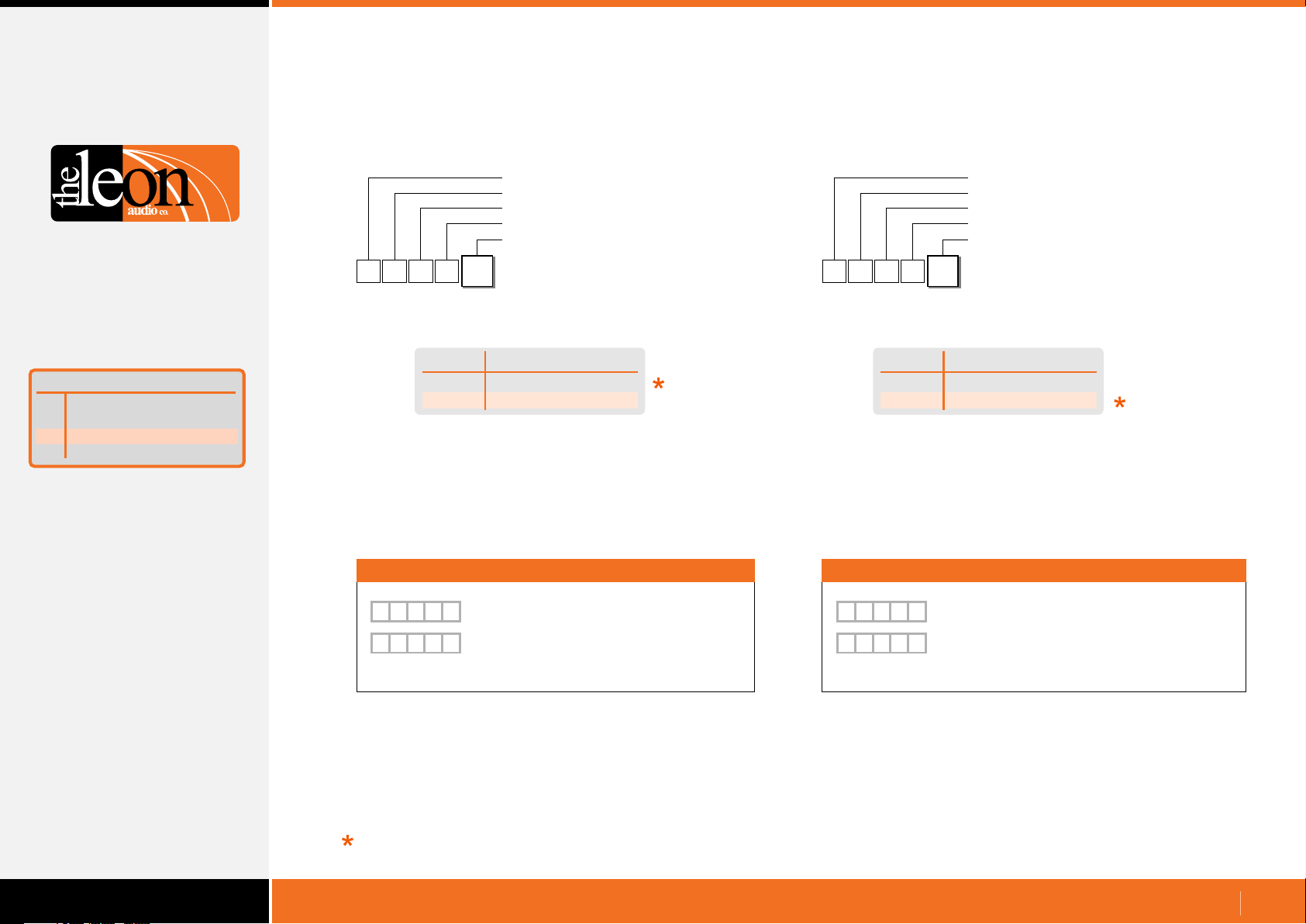
Configuration Commands
Sensor Outstation Functions
Function
Unsafe Lamp
1
Safe when... open/closed
2
End Of Line Resistors
3
All Lamps on Outstation
4
Summary of Sensor
Outstation Functions
End Of Line Resistors
•
Configuration Header
Master number (0-6)
Channel number (0-16)
End Of Line Resistors
Value
{
1
Either a letter or a number can be used for the ASCII Value.
Use which ever you prefer. Letters are not case sensitive.
5
0 or N
2 or T
3
0
End Of Line Resistors
None
Two
Examples
All Lamps on Outstation
•
Configuration Header
Master number (0-6)
Channel number (0-16)
All Lamps on Outstation
Value
{
Either a letter or a number can be used for the ASCII Value.
Use which ever you prefer. Letters are not case sensitive.
1
5
4
Value
0 or D
1 or E
1
All Lamps on OutstationValue
Disabled (off)
Enabled
Examples
{
5
3
1
{
5
3
1
Factory default
0
Master 1, Ch5, No End Of Line Resistors
2
Master 1, Ch5, Two End Of Line Resistors
{
5
4
1
{
1
0
Master 1, Ch5, All Lamps on Outstation disabled
5
4
E
Master 1, Ch5, All Lamps on Outstation enabled
www.LeonAudio.com.au
51.
Page 52
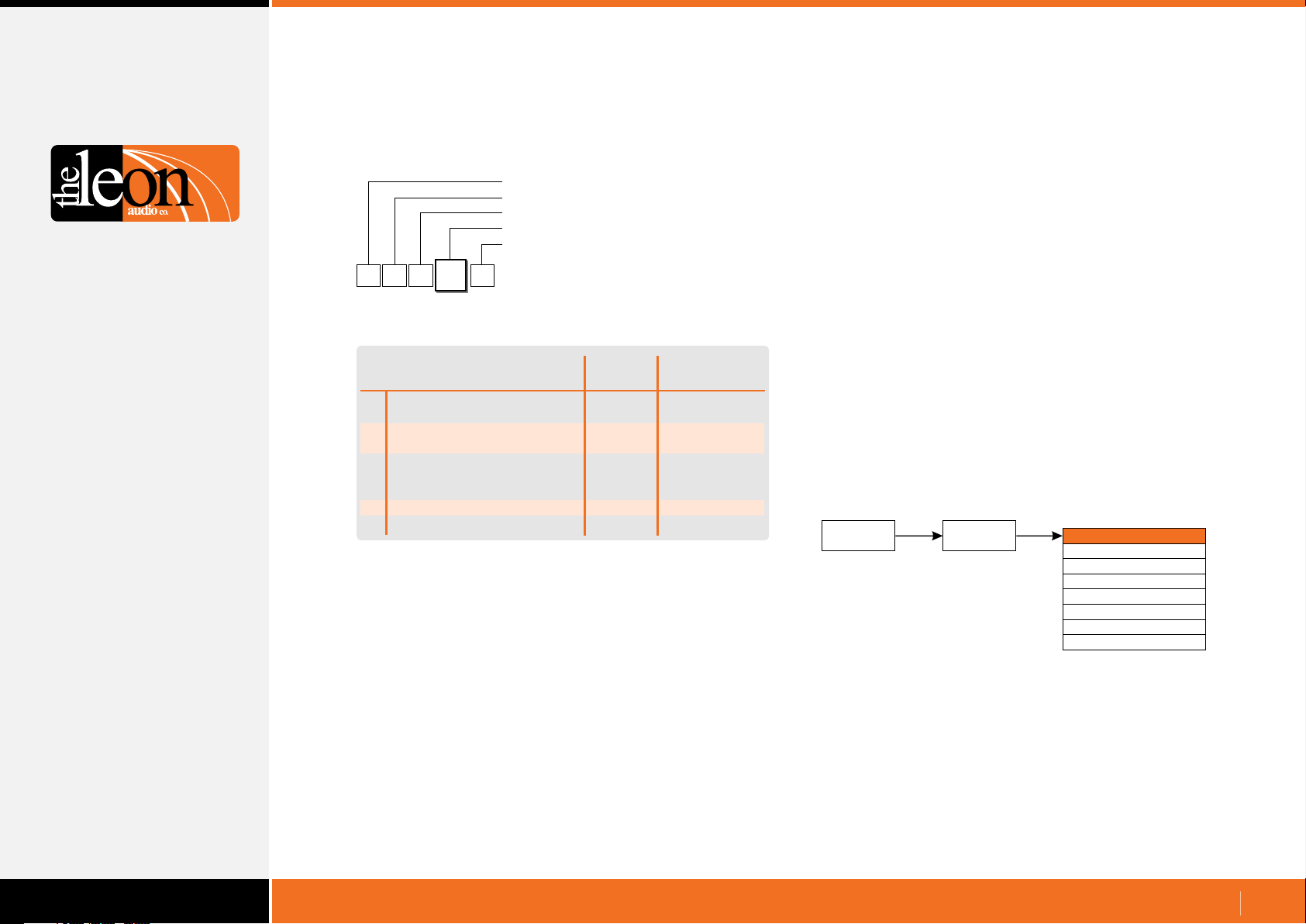
Configuration Commands
Master Station Functions
Configuration Header
Master number (0-6)
Master Config (fixed value)
Function
Value (depends on function)
{
Summary of Master Station Functions
M
1
A
B
C
E
F
A
Function
Copy 1 of 8 files to PC
Copy 1 of 7 files to the
ShowTime file.
Copy ShowTime file to
Installer's Default or
1 of 4 User files.
Go Cue Total Duration
Link 4 Group Master buttons
Master Station Functions
1
Factory
Default
15 Secs
Linked
User Selectable
Function
1-16 Secs
Not Linked
The Master Station contains 8 files.
1: User file 1 (read/write)
2: User file 2 (read/write)
3: User file 3 (read/write)
4: User file 4 (read/write)
5: ShowTime file (read/write)
6: Installer’s Defaults (read/write)
7: Factory Defaults with red Standby lamps. (read only)
8: Factory Defaults with yellow Standby lamps. (read only)
When the Master Station powers up, it reads the ShowTime
file to run the Cue Light system.
Configuration Commands for the Cue Light, Relay or Sensor
Outstations (see pages 26-58) are written to the ShowTime file.
PC / Show
Controller
Configuration Commands are written to the ShowTime File.
PCinterface
QL-PCi
ShowTime file
User file 1
User file 2
User file 3
User file 4
Defaults (red S/by)
Defaults (yellow S/by)
Installer’s Defaults
www.LeonAudio.com.au
52.
Page 53
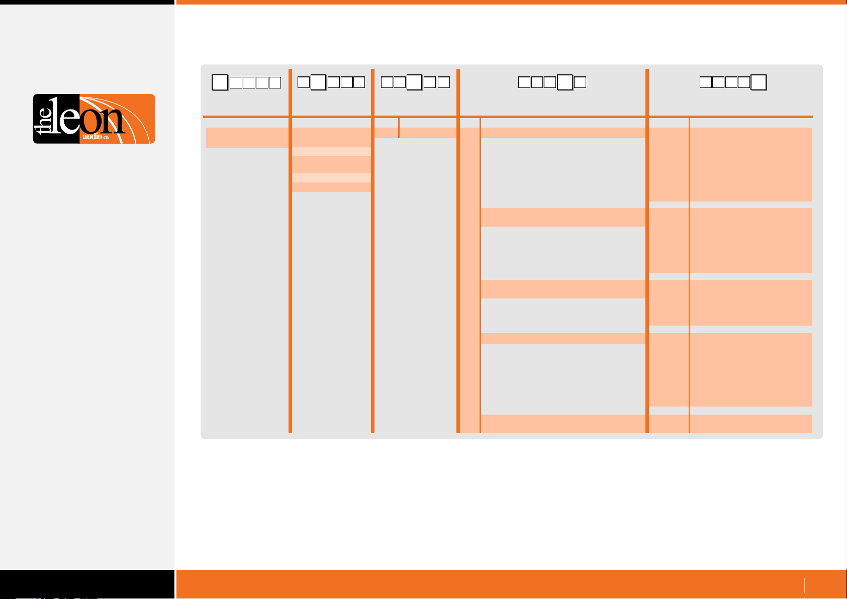
Table of Master Station Configuration Commands
E
M
1
{
Configuration
Commands
Header Byte
(Left curly bracket)
{
6
1
6M E
M
6{E1
{
6M1
E 6
{
EM1
Master
number Master Config
M Fixed value0 (Global)
1
2
3
4
5
6
Function
Description Description
Copy 1 of 8 files to PC
A
Copy 1 of 7 files to ShowTime file
B
Copy ShowTime file to Installer's Default
C
or 1 of 4 User files.
Go Cue Total Duration (1 to 16 seconds)
E
0
1
2
3
4
5
6
7
0
1
2
3
4
6
7
0
1
2
3
4
1 to 9
A or (10)
B or (11)
C or (12)
D or (13)
E or (14)
F or (15)
G or (16)
Value
Installer's Default file
User file 1
User file 2
User file 3
User file 4
ShowTime file
Factory default (red S/by)
Factory default (yellow S/by)
Installer's Default file
User file 1
User file 2
User file 3
User file 4
Factory default (red S/by)
Factory default (yellow S/by)
Installer's Default file
User file 1
User file 2
User file 3
User file 4
1 to 9 seconds
10 seconds Note 1
11 seconds
12 seconds
13 seconds
14 seconds
15 seconds
16 seconds
Note 1: Double digits can be in round brackets e.g. (12)
Link the 4 Group Master buttons between
F
multiple Masters
0
1
Not linked
Linked
www.LeonAudio.com.au
53.
Page 54
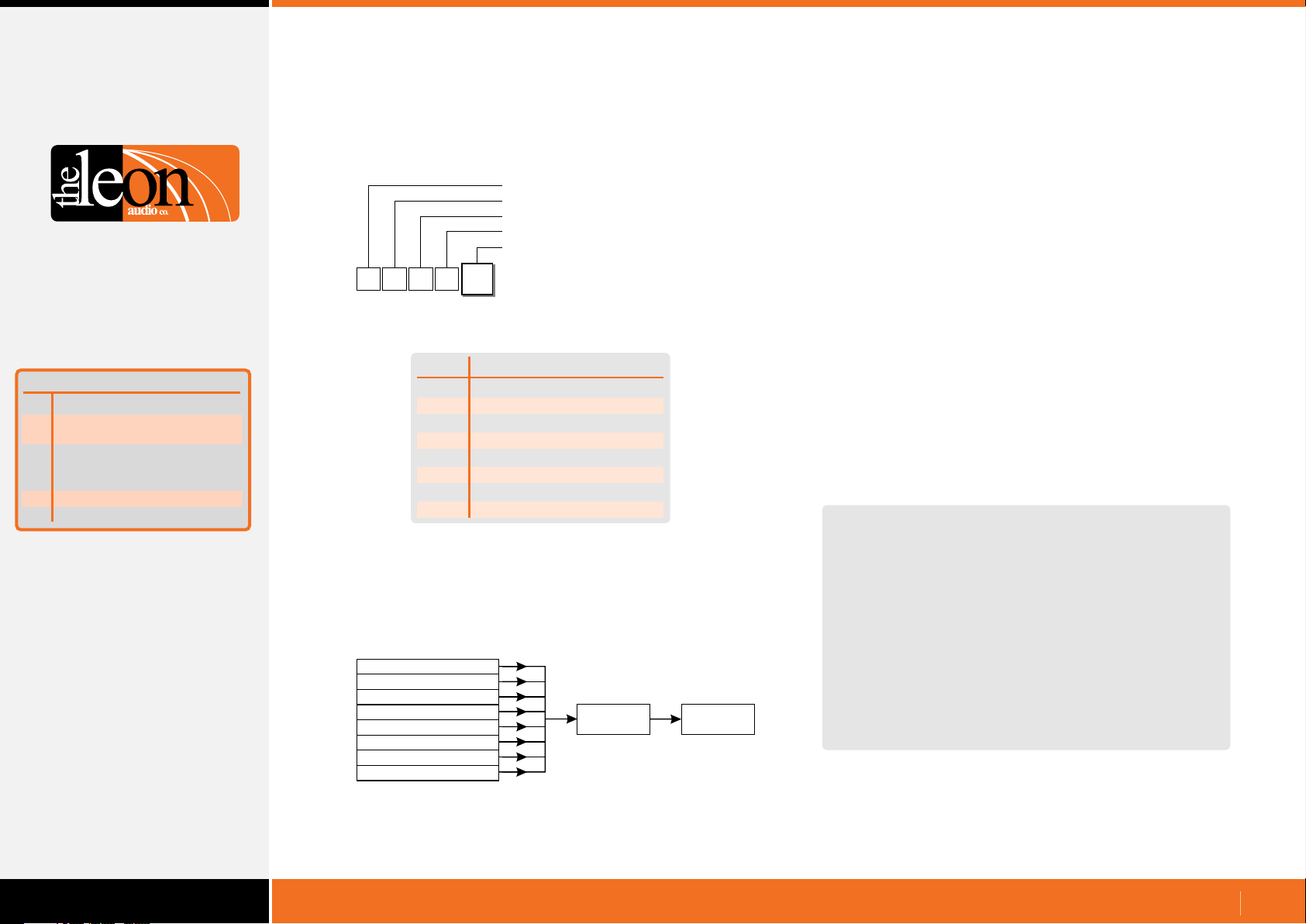
Configuration Commands
Master Station Functions
Copy 1 of 8 files to PC
•
The configuration file begins with the header {NSOF which marks
the Start Of File.
The file is terminated with {NEOF which marks the End Of File.
Function
Copy 1 of 8 files to PC
A
Copy 1 of 7 files to the
B
ShowTime file.
Copy ShowTime file to
C
Installer's Default
or 1 of 4 User files
E
Go Cue Total Duration
F
Link 4 Group Master buttons
Summary of Master
Station Functions
Configuration Header
Master number (0-6)
Master Config. (fixed value)
Copy 1 of 8 files to PC
Value
{
1
M
Value
A
1
Copy 1 of 8 files to PC
Installer's Defaults
0
User file 1
1
User file 2
2
User file 3
3
User file 4
4
5
ShowTime file
6
Factory default (red S/by)
7
Factory default (yellow S/by)
The file is an ASCII text file which can be edited if required.
All or part of the file can be uploaded to the PCinterface simply
by copying it to the PCinterface’s comms port. There is no
special command needed to upload the file.
Installer's Defaults
User file 1
User file 2
User file 3
User file 4
ShowTime file
Defaults (red S/by)
Defaults (yellow S/by)
PCinterface
QL-PCi
PC / Show
Controller
Any file can be copied to the PC/Show Controller.
The file is in the form of Configuration Commands for each
channel, grouped by Function. The file is arranged in 4 sections
covering configuration of Cue Light, Relay and Sensor
Outstations; and the Master Station.
These Configuration Commands and their format is exactly the
same as those described in this document starting on page 26 so
that the file can be copied, without change, back to the
PCinterface to re/configure the system.
A Summary of Commands starting on page 71 may also be a
handy.
A sample of a downloaded configuration follows. It is for Factory
Default with Yellow Standby lamp for Master #1.
It was created by sending {1MA7 to the PCinterface.
As this command executes as soon as it is received, an X for
eXecute is not required.
{NSOF
; Start of file
; Configuration file for Master number 1. File: Factory Default (Yellow S/by)
; Comments are prefixed with a semicolon ';' (3Bh) and end at the next 'Line Feed' (0Ah)
; 5 byte commands start with '{' and can be editied if needed.
; Byte 1: { Header
; Byte 2: Master number
; Byte 3: Channel number
; Byte 4: Function (e.g. S/by Colour)
; Byte 5: Value (e.g. Red/yellow)
; Lines with 16 digits are a summary of the Values in following command lines.
; Ch1 1111 1111 1111 1111 Ch16
; Copy this whole file to the PCinterface to configure the system using the settings below.
; Set the baud rate to a maximum of 38,400 baud for this file transfer or the UART buffer
; in the PCinterface will overflow.
; A Transmit Delay or Pacing of at least 0.5mS/char will allow higher baud rates up to 115,200 to be used.
; Should the UART buffer overflow a '{FULL' error message is sent.
Sample Configuration File. Part 1 of 4
www.LeonAudio.com.au
54.
Page 55

Configuration Commands
Master Station Functions
Copy 1 of 8 files to PC
•
Function
Copy 1 of 8 files to PC
A
Copy 1 of 7 files to the
B
ShowTime file.
Copy ShowTime file to
C
Installer's Default
or 1 of 4 User files
E
Go Cue Total Duration
F
Link 4 Group Master buttons
Summary of Master
Station Functions
; ############################ Cue Light Outstations (QLS & QLS-B) #######################
; Standby Red/Yellow. 1=Yellow 0=Red
; Ch1 1111 1111 1111 1111 Ch16
{11A1 {12A1 {13A1 {14A1 {15A1 {16A1 {17A1 {18A1 {19A1 {1AA1 {1BA1 {1CA1 {1DA1 {1EA1 {1FA1 {1GA1
; S/by Flash on Master. 1=Flash 0=Steady
; Ch1 1111 1111 1111 1111 Ch16
{11B1 {12B1 {13B1 {14B1 {15B1 {16B1 {17B1 {18B1 {19B1 {1AB1 {1BB1 {1CB1 {1DB1 {1EB1 {1FB1 {1GB1
; S/by Flash on Outstation. 1=Flash 0=Steady
; Ch1 1111 1111 1111 1111 Ch16
{11C1 {12C1 {13C1 {14C1 {15C1 {16C1 {17C1 {18C1 {19C1 {1AC1 {1BC1 {1CC1 {1DC1 {1EC1 {1FC1 {1GC1
; S/by latches. 1=Latches 0=Momentary
; Ch1 1111 1111 1111 1111 Ch16
{11D1 {12D1 {13D1 {14D1 {15D1 {16D1 {17D1 {18D1 {19D1 {1AD1 {1BD1 {1CD1 {1DD1 {1ED1 {1FD1 {1GD1
; S/by DIM on Ack. 1=Dim 0=No Dim
; Ch1 0000 0000 0000 0000 Ch16
{11E0 {12E0 {13E0 {14E0 {15E0 {16E0 {17E0 {18E0 {19E0 {1AE0 {1BE0 {1CE0 {1DE0 {1EE0 {1FE0 {1GE0
; Go Flickers. 1=Flicker 0=No Flicker
; Ch1 0000 0000 0000 0000 Ch16
{11F0 {12F0 {13F0 {14F0 {15F0 {16F0 {17F0 {18F0 {19F0 {1AF0 {1BF0 {1CF0 {1DF0 {1EF0 {1FF0 {1GF0
; Go times-out. 1=Times-out 0=No time-out
; Ch1 1111 1111 1111 1111 Ch16
{11G1 {12G1 {13G1 {14G1 {15G1 {16G1 {17G1 {18G1 {19G1 {1AG1 {1BG1 {1CG1 {1DG1 {1EG1 {1FG1 {1GG1
; Go flashes. 1=Flashes after 3 secs. 0=Steady
; Ch1 1111 1111 1111 1111 Ch16
{11H1 {12H1 {13H1 {14H1 {15H1 {16H1 {17H1 {18H1 {19H1 {1AH1 {1BH1 {1CH1 {1DH1 {1EH1 {1FH1 {1GH1
; Go latches. 1=Latches 0=Momentary
; Ch1 1111 1111 1111 1111 Ch16
{11J1 {12J1 {13J1 {14J1 {15J1 {16J1 {17J1 {18J1 {19J1 {1AJ1 {1BJ1 {1CJ1 {1DJ1 {1EJ1 {1FJ1 {1GJ1
; Go & S/by interlocked. 1=Interlocked 0=Independant
; Ch1 1111 1111 1111 1111 Ch16
{11K1 {12K1 {13K1 {14K1 {15K1 {16K1 {17K1 {18K1 {19K1 {1AK1 {1BK1 {1CK1 {1DK1 {1EK1 {1FK1 {1GK1
; Call LED enabled. 1=Enabled 0=Disabled
; Ch1 1111 1111 1111 1111 Ch16
{11M1 {12M1 {13M1 {14M1 {15M1 {16M1 {17M1 {18M1 {19M1 {1AM1 {1BM1 {1CM1 {1DM1 {1EM1 {1FM1 {1GM1
; Call LED Flashes. 1=Flashes 0=Steady
; Ch1 1111 1111 1111 1111 Ch16
{11N1 {12N1 {13N1 {14N1 {15N1 {16N1 {17N1 {18N1 {19N1 {1AN1 {1BN1 {1CN1 {1DN1 {1EN1 {1FN1 {1GN1
; ACK button backlight. 1=On 0=Off
; Ch1 1111 1111 1111 1111 Ch16
{11P1 {12P1 {13P1 {14P1 {15P1 {16P1 {17P1 {18P1 {19P1 {1AP1 {1BP1 {1CP1 {1DP1 {1EP1 {1FP1 {1GP1
; Beeper Enable. 1=On 0=Off
; Ch1 1111 1111 1111 1111 Ch16
{11Q1 {12Q1 {13Q1 {14Q1 {15Q1 {16Q1 {17Q1 {18Q1 {19Q1 {1AQ1 {1BQ1 {1CQ1 {1DQ1 {1EQ1 {1FQ1 {1GQ1
; Beep-On-Go. 0=Off, 1=1mS, 2=50mS, 3=200mS
; Ch1 0000 0000 0000 0000 Ch16
{11R0 {12R0 {13R0 {14R0 {15R0 {16R0 {17R0 {18R0 {19R0 {1AR0 {1BR0 {1CR0 {1DR0 {1ER0 {1FR0 {1GR0
; Change colour on ACK. 0=No colour change 1=Change colour
; Ch1 0000 0000 0000 0000 Ch16
{11S0 {12S0 {13S0 {14S0 {15S0 {16S0 {17S0 {18S0 {19S0 {1AS0 {1BS0 {1CS0 {1DS0 {1ES0 {1FS0 {1GS0
; Dimmer (1-5). 1=dimmest 5=brightest (100%)
; Ch1 5555 5555 5555 5555 Ch16
{11T5 {12T5 {13T5 {14T5 {15T5 {16T5 {17T5 {18T5 {19T5 {1AT5 {1BT5 {1CT5 {1DT5 {1ET5 {1FT5 {1GT5
; ############################ Relay Outstations (QLR) ###################################
; Relay Mode
; 1 = A: Momentary B: Momentary
; 2 = A: Latch B: Latch
; 3 = A: Monentary B: Latch
; 4 = A: Latch B: Momentary
; 5 = Cue Light Mode
; Ch1 1111 1111 1111 1111 Ch16
{11a1 {12a1 {13a1 {14a1 {15a1 {16a1 {17a1 {18a1 {19a1 {1Aa1 {1Ba1 {1Ca1 {1Da1 {1Ea1 {1Fa1 {1Ga1
; Relay: S/by Flash on Master. 1=Flash 0=Steady
; Ch1 1111 1111 1111 1111 Ch16
{11b1 {12b1 {13b1 {14b1 {15b1 {16b1 {17b1 {18b1 {19b1 {1Ab1 {1Bb1 {1Cb1 {1Db1 {1Eb1 {1Fb1 {1Gb1
; Relay: S/by Flash on Outstation. 1=Flash 0=Steady
; Ch1 1111 1111 1111 1111 Ch16
{11c1 {12c1 {13c1 {14c1 {15c1 {16c1 {17c1 {18c1 {19c1 {1Ac1 {1Bc1 {1Cc1 {1Dc1 {1Ec1 {1Fc1 {1Gc1
; Relay: S/by latches. 1=Latches 0=Momentary
; Ch1 1111 1111 1111 1111 Ch16
{11d1 {12d1 {13d1 {14d1 {15d1 {16d1 {17d1 {18d1 {19d1 {1Ad1 {1Bd1 {1Cd1 {1Dd1 {1Ed1 {1Fd1 {1Gd1
; Relay: Go times-out. 1=Times-out 0=No time-out
; Ch1 1111 1111 1111 1111 Ch16
{11e1 {12e1 {13e1 {14e1 {15e1 {16e1 {17e1 {18e1 {19e1 {1Ae1 {1Be1 {1Ce1 {1De1 {1Ee1 {1Fe1 {1Ge1
; Relay: Go flashes. 1=Flashes after 3 secs. 0=Steady
; Ch1 1111 1111 1111 1111 Ch16
{11f1 {12f1 {13f1 {14f1 {15f1 {16f1 {17f1 {18f1 {19f1 {1Af1 {1Bf1 {1Cf1 {1Df1 {1Ef1 {1Ff1 {1Gf1
; Relay: Go latches. 1=Latches 0=Momentary
; Ch1 1111 1111 1111 1111 Ch16
{11g1 {12g1 {13g1 {14g1 {15g1 {16g1 {17g1 {18g1 {19g1 {1Ag1 {1Bg1 {1Cg1 {1Dg1 {1Eg1 {1Fg1 {1Gg1
; Relay: Go & S/by interlocked. 1=Interlocked 0=Independant
; Ch1 1111 1111 1111 1111 Ch16
{11h1 {12h1 {13h1 {14h1 {15h1 {16h1 {17h1 {18h1 {19h1 {1Ah1 {1Bh1 {1Ch1 {1Dh1 {1Eh1 {1Fh1 {1Gh1
; Relay: Call LED enabled. 1=Enabled 0=Disabled
; Ch1 1111 1111 1111 1111 Ch16
{11j1 {12j1 {13j1 {14j1 {15j1 {16j1 {17j1 {18j1 {19j1 {1Aj1 {1Bj1 {1Cj1 {1Dj1 {1Ej1 {1Fj1 {1Gj1
; Relay: Call LED Flashes. 1=Flashes 0=Steady
; Ch1 1111 1111 1111 1111 Ch16
{11k1 {12k1 {13k1 {14k1 {15k1 {16k1 {17k1 {18k1 {19k1 {1Ak1 {1Bk1 {1Ck1 {1Dk1 {1Ek1 {1Fk1 {1Gk1
; Relay: All lamps enabled. 1=Enabled 0=Disabled
; Ch1 1111 1111 1111 1111 Ch16
{11m1 {12m1 {13m1 {14m1 {15m1 {16m1 {17m1 {18m1 {19m1 {1Am1 {1Bm1 {1Cm1 {1Dm1 {1Em1 {1Fm1 {1Gm1
Sample Configuration File. Part 3 of 4
Sample Configuration File. Part 2 of 4
www.LeonAudio.com.au
55.
Page 56

Configuration Commands
Master Station Functions
Copy 1 of 8 files to PC
•
Function
Copy 1 of 8 files to PC
A
Copy 1 of 7 files to the
B
ShowTime file.
Copy ShowTime file to
C
Installer's Default
or 1 of 4 User files
Go Cue Total Duration
E
Link 4 Group Master buttons
F
Summary of Master
Station Functions
; ############################ Sensor Outstations (QTS) ##################################
; Sensor: Unsafe LED. 1=Flash 0=Steady
; Ch1 1111 1111 1111 1111 Ch16
{1111 {1211 {1311 {1411 {1511 {1611 {1711 {1811 {1911 {1A11 {1B11 {1C11 {1D11 {1E11 {1F11 {1G11
; Sensor: Safe when open/closed. 1=Closed 0=Open
; Ch1 0000 0000 0000 0000 Ch16
{1120 {1220 {1320 {1420 {1520 {1620 {1720 {1820 {1920 {1A20 {1B20 {1C20 {1D20 {1E20 {1F20 {1G20
; Sensor: End Of Line Resistors. 2=2 Resistors 0=None
; Ch1 0000 0000 0000 0000 Ch16
{1130 {1230 {1330 {1430 {1530 {1630 {1730 {1830 {1930 {1A30 {1B30 {1C30 {1D30 {1E30 {1F30 {1G30
; Sensor: All lamps enabled. 1=Enabled 0=Disabled
; Ch1 1111 1111 1111 1111 Ch16
{1141 {1241 {1341 {1441 {1541 {1641 {1741 {1841 {1941 {1A41 {1B41 {1C41 {1D41 {1E41 {1F41 {1G41
; ############################ Master Config (QLM16) #####################################
; Master: GoCueTotalDuration. 1-16 seconds. (A-G represents 10-16)
; F Seconds
{1MEF
; Master: Link the 4 Group Master buttons. 1=Linked 0=Not linked
; 1
{1MF1
; Execute all the above commands when this file is sent to the PCinterface (QL-PCi)
X
; End of file
{NEOF
Sample Configuration File. Part 4 of 4
Technical note
The PCinterface has a 500 byte FIFO (First In First Out) memory
for receiving incoming RS232/485 commands. The FIFO allows
commands to be received and stored even if the PCinterface is
momentarily busy with other tasks.
Incoming commands are read from the FIFO, processed and
stored in a memory buffer until the letter X for eXecute is received.
The data in the buffer is then uploaded to the Cue Light Master
Station. This allows multiple commands to be uploaded to the
Master Station at the same instant.
Spaces are not permitted except between each 5 byte command
and/or the letter X.
www.LeonAudio.com.au
56.
Page 57
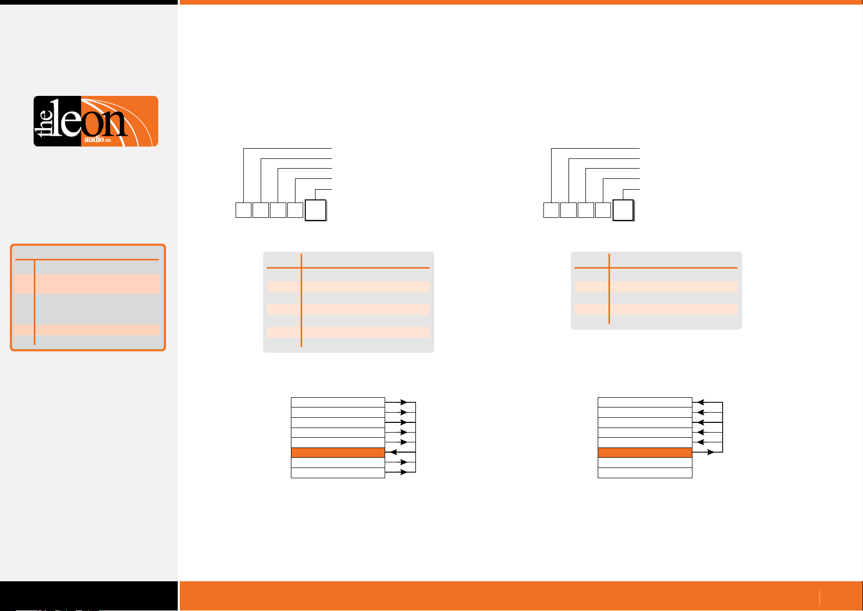
Configuration Commands
Master Station Functions
Function
Copy 1 of 8 files to PC
A
Copy 1 of 7 files to the
B
ShowTime file.
Copy ShowTime file to
C
Installer's Default
or 1 of 4 User files
Go Cue Total Duration
E
Link 4 Group Master buttons
F
Summary of Master
Station Functions
Copy 1 of 7 files to the ShowTime file
•
Configuration Header
Master number (0-6)
Master Config. (fixed value)
Copy 1 of 7 files to the ShowTime file
Value
{
1
M
Value
0
1
2
3
4
6
7
B
1
Copy 1 of 7 files to Showtime
Installer's Defaults
User file 1
User file 2
User file 3
User file 4
Factory default (red S/by)
Factory default (yellow S/by)
Copy ShowTime file to Installer's Default
•
or 1 of 4 User files
Configuration Header
Master number (0-6)
Master Config. (fixed value)
Copy ShowTime file to 1 of 5 files
Value
{
1
M
Value
0
1
2
3
4
C
1
Copy Showtime to 1 of 5 files
Installer's Defaults
User file 1
User file 2
User file 3
User file 4
Installer's Defaults
User file 1
User file 2
User file 3
User file 4
ShowTime file
Defaults (red S/by)
Defaults (yellow S/by)
Any file can be copied to the ShowTime file. ShowTime file can be copied to most other files.
The ShowTime file can be copied to any of the four User files or
to the Installer’s Defaults file.
The two Factory Default files are read only.
Installer's Defaults
User file 1
User file 2
User file 3
User file 4
ShowTime file
Defaults (red S/by)
Defaults (yellow S/by)
www.LeonAudio.com.au
57.
Page 58
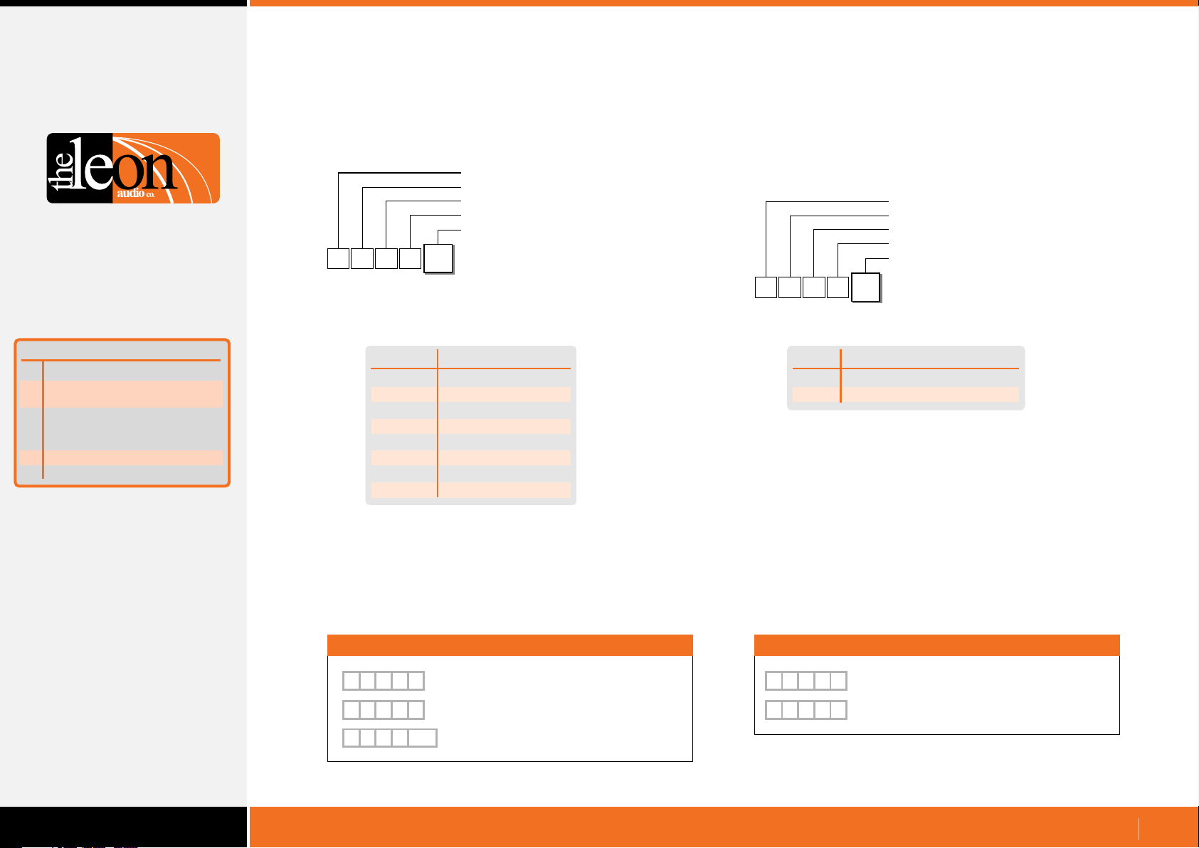
Configuration Commands
Master Station Functions
Function
Copy 1 of 8 files to PC
A
Copy 1 of 7 files to the
B
ShowTime file.
Copy ShowTime file to
C
Installer's Default
or 1 of 4 User files
Go Cue Total Duration
E
Link 4 Group Master buttons
F
Summary of Master
Station Functions
Go Cue Total Duration
•
Configuration Header
Master number (0-6)
Master Config. (fixed value)
Go Cue Total Duration
Value
{
This setting applies to all channels.
Individual channels can still be set to flash or burn steady.
Either a letter or a number can be used for the ASCII Value.
Use which ever you prefer. Letters are not case sensitive.
Values of A-G can be replaced by a double digit number inside
curved brackets
M
1
Value
A or (10)
B or (11)
C or (12)
D or (13)
E or (14)
F or (15)
G or (16)
1-9
E
1
Go Cue Total Duration
1 to 9 seconds
10 seconds
11 seconds
12 seconds
13 seconds
14 seconds
15 seconds
16 seconds
Link 4 Group Master buttons
•
Configuration Header
Master number (0-6)
Master Config. (fixed value)
Link 4 Group Master buttons
Value
{
1
M
Value
0
1
F
1
Link 4 Group Master buttons
Not Linked
Linked
Examples
[
M
1
[
M
1
[
M E
1
Examples
[
M
E
6
Master 1, Go Cue duration = 6 seconds
E
C
Master 1, Go Cue duration = 12 seconds
( )
12
Master 1, Go Cue duration = 12 seconds
[
F
1
1
0
Master 1, 4 Group Master buttons not linked
M
F
1
Master 1, 4 Group Master buttons linked
www.LeonAudio.com.au
58.
Page 59
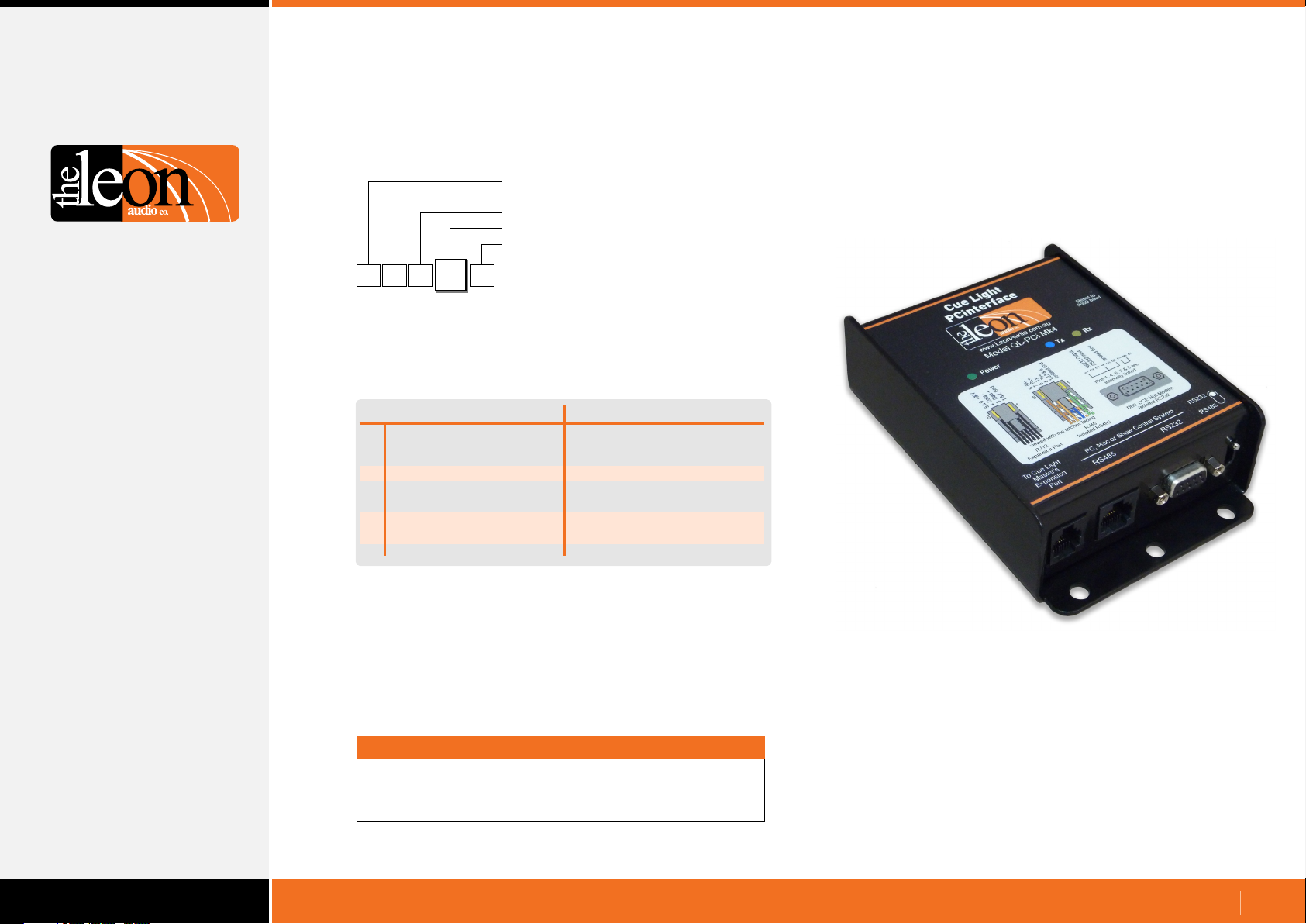
Configuration Commands
PCinterface Functions
Configuration Header
PCinterface (fixed value)
PCinterface (fixed value)
Function
Value (depends on function)
{
R
C
Function
R
Monitoring Reply Mode
B
Baud Rate
H
Heart Beat Signal
P
T
PCinterface Functions
(Idle Character)
Reply Pacing. Pause
between each 5 byte reply
Terminator chx for replies
R
0
PCinterface Functions
Values
Simple GUI Reply
or Channel & Function Reply
2400 to 115200
on/off
0uS, 100uS, 300uS, 1mS,
3mS, 10mS, 30mS
None } | <space> <LF> ~
PCinterface
QL-PCi mk4
Note
As these commands execute as soon as they are received,
an X for eXecute is not required.
www.LeonAudio.com.au
59.
Page 60
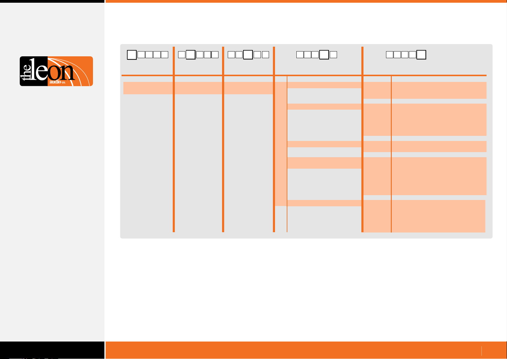
Table of PCinterface Configuration Commands
R 5
C
{
Configuration
Commands
Header Byte
(Left curly bracket)
{
R
PCinterface
( )
fixed value
5C BB
C B 5
5{BR
{
5CR
{
PCinterface
( )
fixed value
CR
R
B
H
P
T
Function
Description Description
Monitoring Reply Mode
Baud Rate
Heart Beat Signal
Reply Pacing. Pause between
each 5 byte reply
Terminator chx for replies
0
1
0
1
2
3
4
5
0
1
0
1
2
3
4
5
6
0
1
2
3
4
5
BCR
Value
Simple GUI Reply
Channel & Function Reply with
all ASCII characters.
2400 baud
9600 baud
19200 baud
38400 baud
57600 baud
115200 baud
Off
On
0uS
100uS
300uS
1mS
3mS
10mS
30mS
none
} 7Dh
| 7Ch
space 20h
line feed 0Ah
~ 7Eh
www.LeonAudio.com.au
60.
Page 61
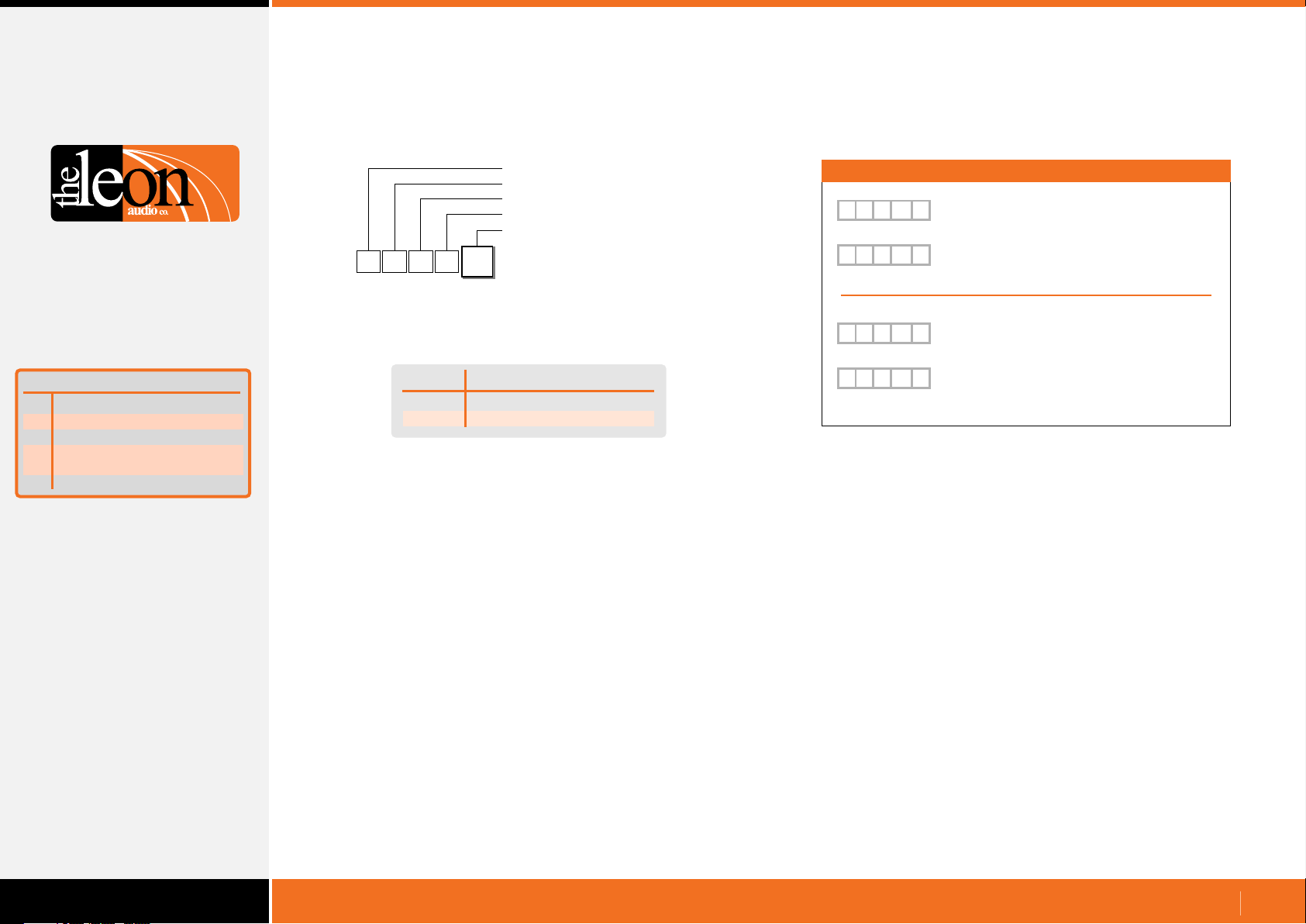
Configuration Commands
PCinterface Functions
Monitoring Reply Mode command
•
Function
Monitoring Reply Mode
R
Baud Rate
B
Heart Beat Signal
H
Reply Pacing. Pause
P
between each 5 byte reply
Terminator chx for replies
T
Summary of
PCinterface Functions
Configuration Header
PCinterface configuration
PCinterface configuration
Monitoring Reply Mode
Value (0-1)
{
R
C
R
Select the data format for Simple GUI Reply and Channel &
Function Reply status monitoring.
Value Command
0
1
This command configures the PCinterface and is remembered
when the power is off.
It does not require the X for eXecute as it is not uploaded to the
Master Station.
It will execute as soon as the 5th byte Value has been received.
Monitoring Reply Mode
0
Simple GUI Reply
Channel & Function Reply
Examples
{
R C R
[
N
1
{
R C R
[
1 1
Command to select
0
Simple GUI Reply mode
92
2
Typical Simple GUI Reply
(Master 1, Ch 1 Go flashing in this example)
1
Command to select
Channel & Function Reply mode.
Typical Channel & Function Reply
G
2
(Master 1, Ch 1 Go flashing in this example)
www.LeonAudio.com.au
61.
Page 62
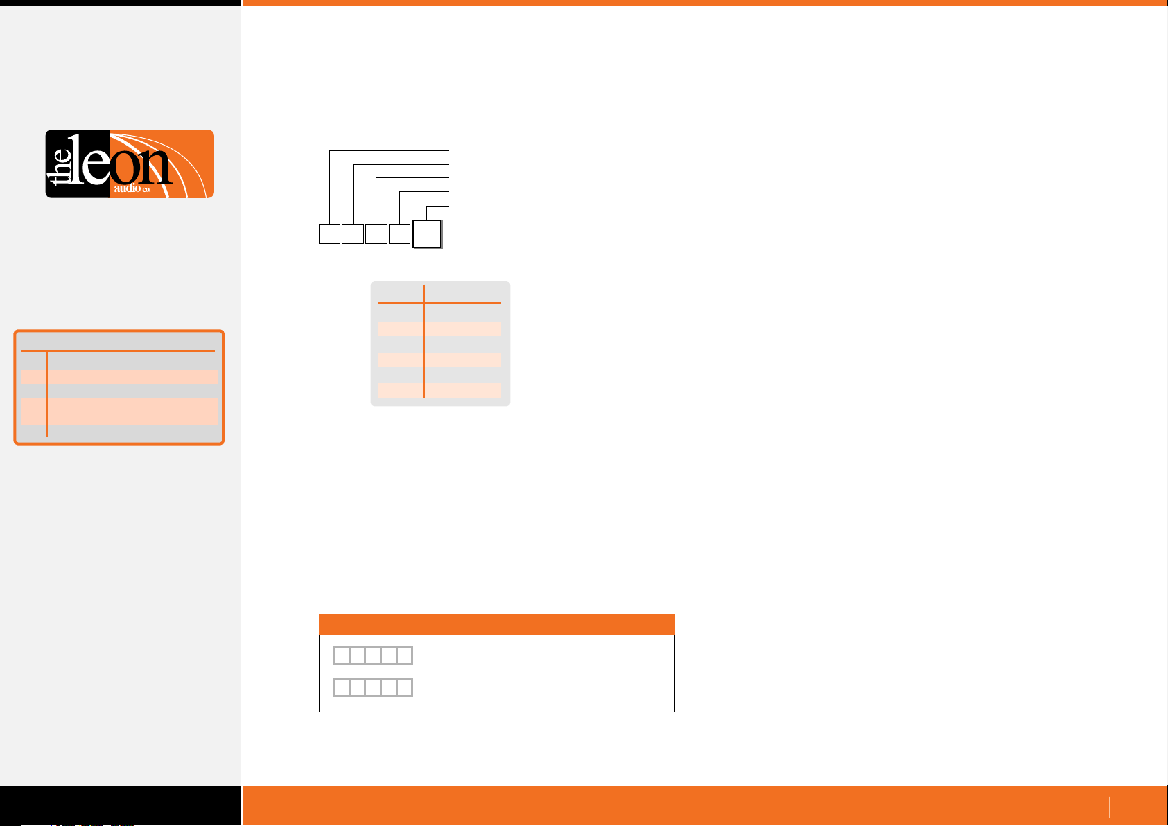
Configuration Commands
PCinterface Configuration
Function
Monitoring Reply Mode
R
Baud Rate
B
Heart Beat Signal
H
Reply Pacing. Pause
P
between each 5 byte reply
Terminator chx for replies
T
Summary of
PCinterface Functions
Baud Rate
•
Configuration Header
PCinterface configuration
PCinterface configuration
Baud Rate
Value (0-5)
{
R
C
B
Value
0
1
2
3
4
5
This sets the baud rate for both the RS232 and RS485 serial
comms ports.
This command configures the PCinterface and is remembered
when the power is off.
It does not require the X for eXecute as it is not uploaded to the
Master Station.
It will execute as soon as the 5th byte Value has been received.
0
Baud Rate
2,400
9,600
19,200
38,400
57,600
115,200
Baud Rate
Manual Reset to 9600 baud.
•
This is a debugging tool to reset the PCinterface to 9600
baud rate for those times when one loses control due to
an incorrect baud rate setting.
The following procedure is not meant to be too simple
because we do not want any unqualified fingers resetting
the baud rate of the PCinterface once it has been installed.
•
Unplug the PCinterface from the Cue Light Master.
Press and hold the recessed Reset to 9600 baud button.
•
(A straightened out paper clip works well as a tool)
•
Plug the PCinterface into the Cue Light Master.
The Tx and Rx lamps will both flash slowly for about 4
secs.
•
Release the Reset button as soon as the Tx and Rx lamps
start to flash fast. They only flash fast for 500mS so the
window of opportunity is small.
•
If successful, the Rx lamp will burn steady for 2 seconds
and the PCinterface will now be running at 9600 baud.
The new setting is saved when the power is off.
Examples
{
R C
{
R C
B
B
Set baud Rate to 19,200
2
Set baud Rate to 115,200
5
www.LeonAudio.com.au
62.
Page 63
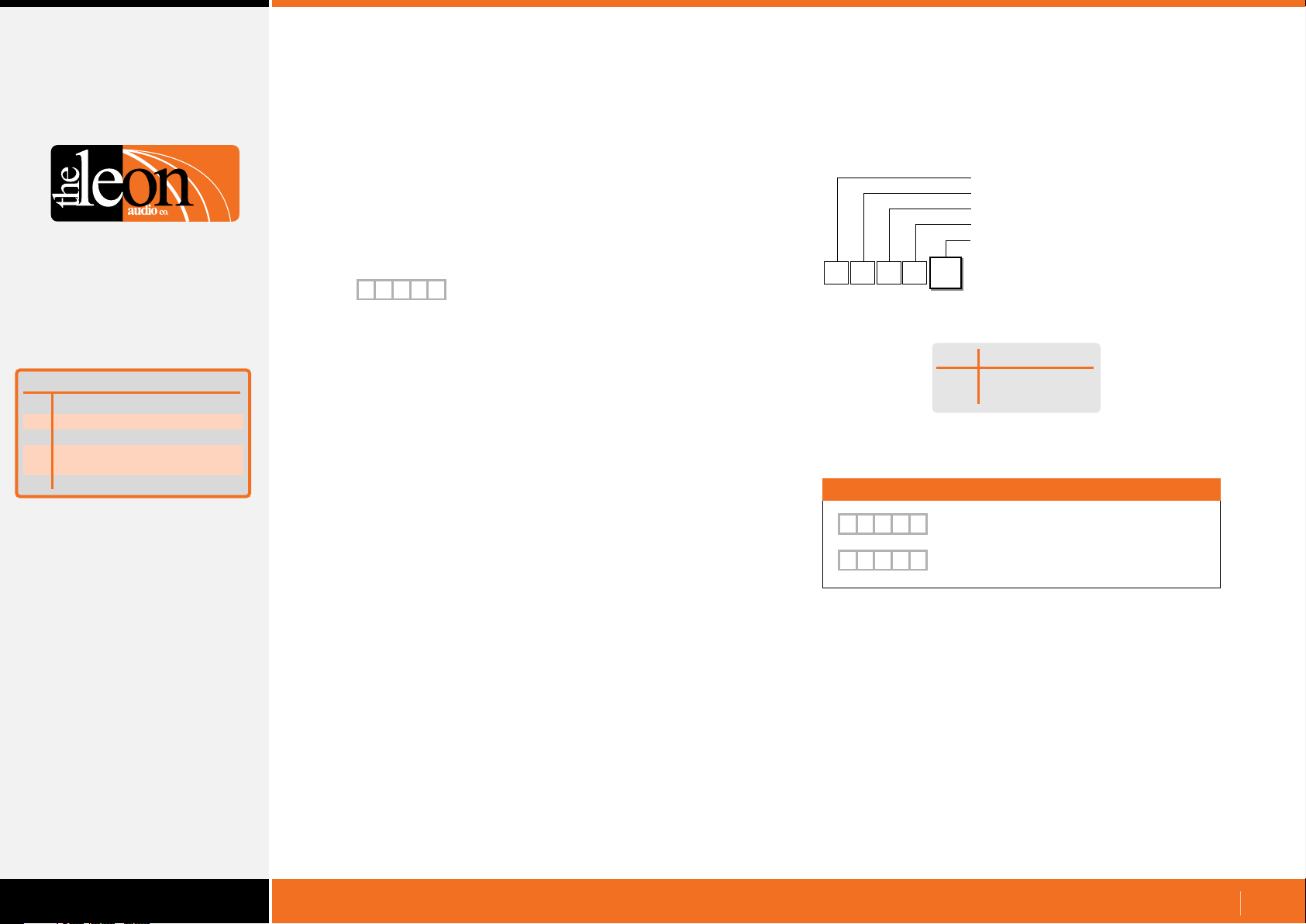
Configuration Commands
PCinterface Configuration
Function
Monitoring Reply Mode
R
Baud Rate
B
Heart Beat Signal
H
Reply Pacing. Pause
P
between each 5 byte reply
Terminator chx for replies
T
Summary of
PCinterface Functions
Heart Beat
•
The Heart Beat signal is generated by the PCinterface unit.
It does not indicate that any Cue Light Outstations are
connected.
The Heart Beat signal is reset to ON when ever the
PCinterface is powered up.
{
R R
This response is sent once every second +/- 5%.
The Heart Beat signal can be turned off but will automatically be
turned back on the next time the PCinterface is powered up.
Heart Beat signal
H
1
Heart Beat on/off command
•
{
HCR
1
Value
0
1
Examples
{
R C
H
{
R C
H
Heart Beat Signal Off
0
Heart Beat Signal On
1
Configuration Header
PCinterface configuration
PCinterface configuration
Heart Beat
Heart Beat on/off Value (0-1)
Heart Beat on/off command
Heart Beat Signal
Off
On
www.LeonAudio.com.au
63.
Page 64
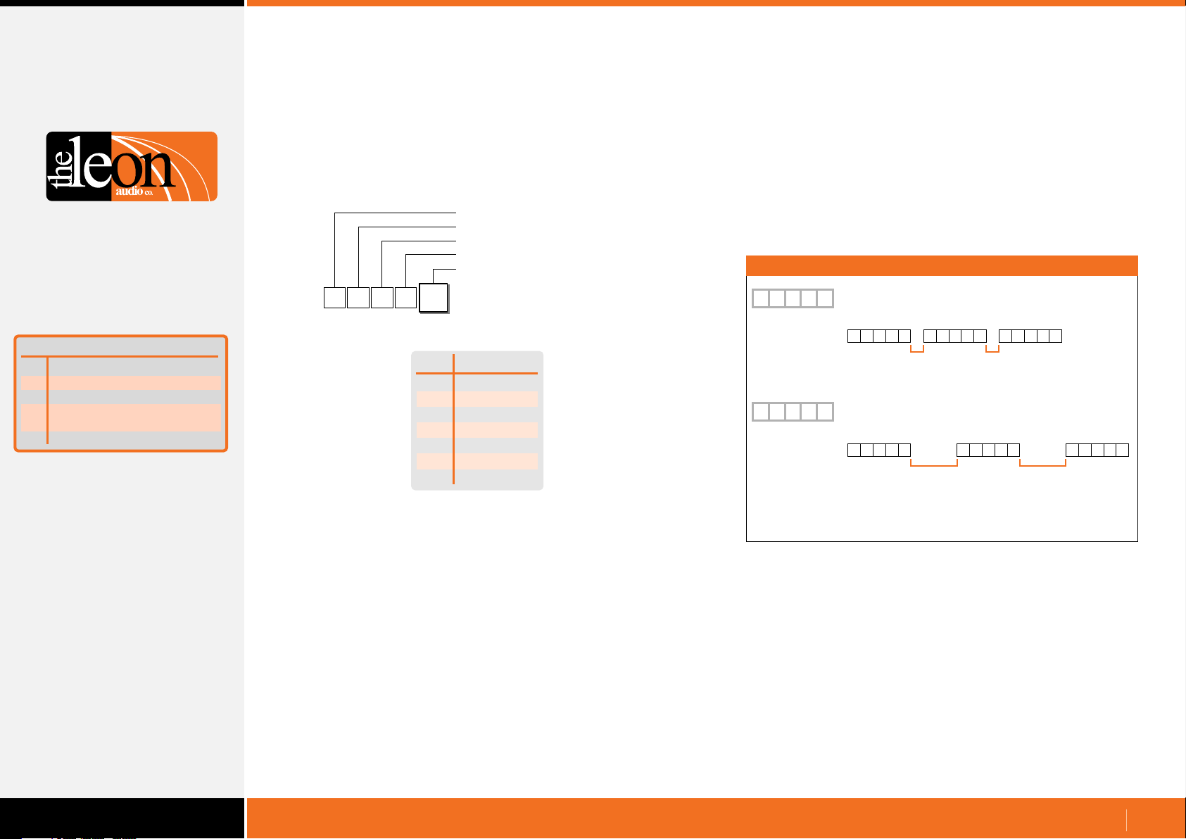
Configuration Commands
PCinterface Configuration
Reply Pacing. Pause between each 5 byte reply
•
Add a pause between each 5 byte reply if the receiving system is
unable to process the incoming data quickly enough.
Configuration Header
PCinterface configuration
PCinterface configuration
Reply Pacing
Reply Pacing Value (0-6)
Examples
Function
Monitoring Reply Mode
R
Baud Rate
B
Heart Beat Signal
H
Reply Pacing. Pause
P
between each 5 byte reply
Terminator chx for replies
T
Summary of
PCinterface Functions
{
R
C
P
Value
No response is given when this command is sent.
The new setting is saved when the power is off.
Use the shortest pause possible or response times may
become unacceptable.
With Pacing set to 0mS, the Request Lamp Status [1SQ1
command takes 63mS to return 560 bytes of data at 115,200
baud.
With Pacing set to 30mS, the same command takes 3.4
seconds to return the same data.
0
0
1
2
3
4
5
6
Reply Pacing
Reply Pacing
no pause
100uS
300uS
1mS
3mS
10mS
30mS
{
{
Note:
These drawings are not to scale.
The duration of the 5 byte replies will vary with baud rate.
P
R C
5 byte reply
P
R C
5 byte reply 5 byte reply
Set Reply Pacing pause to 100uS
1
5 byte reply
1 2 3 4 5 1 2 3 4 5 1 2 3 4 5
100uS min
pause
Set Reply Pacing pause to 1mS
3
1 2 3 4 5 1 2 3 4 5 1 2 3 4 5
1mS min
5 byte reply
100uS min
pause
pause
5 byte reply
1mS min
pause
www.LeonAudio.com.au
64.
Page 65
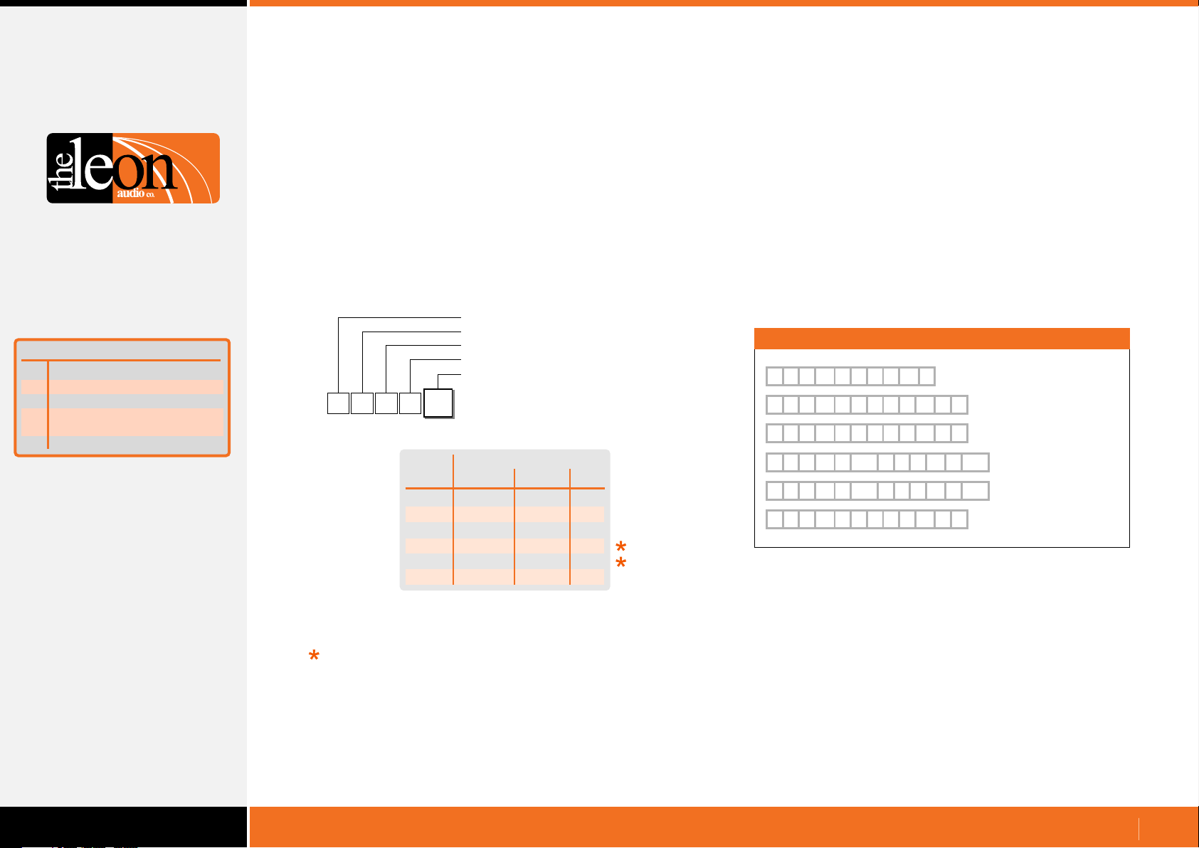
Function
Monitoring Reply Mode
R
Baud Rate
B
Heart Beat @ 1Hz rate
H
Pacing. Pause between
P
each 5 byte reply
Terminator chx for replies
T
Summary of
PCinterface Functions
Configuration Commands
PCinterface Configuration
Termination Character
•
Each 5 byte monitoring reply can be terminated by a special
character.
There is a choice of 5 different termination characters chosen by
the following command.
This command configures the PCinterface and is remembered
when the power is off.
It does not require the X for eXecute as it is not uploaded to the
Master Station.
It will execute as soon as the 5th byte has been received.
Configuration Header
PCinterface configuration
PCinterface configuration
Termination Character
Termination Character Value (0-5)
{
R
C
T
Value
Termination Character
0
Termination Character
ASCII Decimal Hex
0
1
2
3
4
5
none
}
|
space
line feed
~
none
125d
124d
32d
10d
126d
none
7Dh
7Ch
20h
0Ah
7Eh
The repeating HeartBeat reply {RRH1 is used in the examples below.
Termination Character Examples
{
R R H
{
R
{
R
{
R
{
R
{
R
R
R
R
R
R
{
R R H
1
{
} }
H
1
|
H
1
H
20h 20h
1
H
10h 10h
1
~ ~
H
1
R
R
{
R
R
{
R
{
R
{
R
R
1
H
1
H
1
R
H
1
R
H
1
H
1
No terminator
} Right curly bracket
|
| Pipe
Space
Line Feed
~ Tilde
The default terminator as shipped is none.
<Space> and <LF>
The characters may appear in data sent as
part of the Simple GUI Reply and hence are not suitable choices
for terminator characters intended to be read by a machine (PC).
They are however ideal to aid in readability when data is
displayed on a terminal program.
Use } (125d), | (124d) or ~ (126d) as terminator characters to be
read by a machine (PC) as they are not used within any
commands.
www.LeonAudio.com.au
65.
Page 66
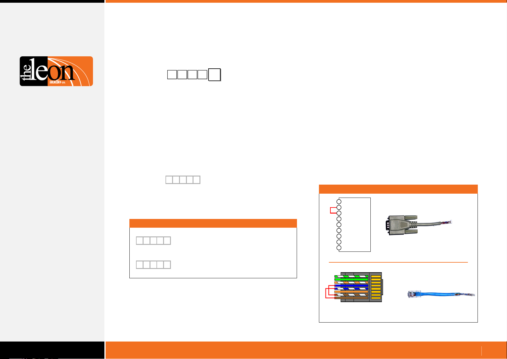
Testing
Testing the PCinterface to PC serial link
Test Comms
Test Comms reply
Example
{
R C
{
R R
{
Test comms to and from the PCinterface.
The 5th byte ? can be any ASCII character of your
choice. It is echoed back as part of the reply.
If no reply is received, check that the Rx lamp winked
when the command was sent. The Rx lamp will wink
when any data is received, even if the baud rate and
data format are wrong. This will help identify where
any problem may lie.
A reply is only sent when the {RC2? command is
received in the correct data format (N81) and at the
correct baud rate.
{
R R
The 5th byte ? is the random character entered as
the 5th byte of the {RC2? command above.
It is echoed back in this reply.
2
?
2
?
2CR
?
2
?
Test comms to and from the PCinterface.
The last byte ? is any ASCII character of
your choice.
Reply.
? is the ASCII character of your choice from
the line above.
PCinterface Loop-back Test
The PCinterface has a built-in test mode.
All you need to run it is a loop-back lead.
When powered up, the PCinterface sends a heartbeat signal once
per second. If this signal is fed back into the PCinterface, it enters
the test mode. It works with any baud rate setting.
Set the RS232/RS485 switch to which ever input you are using.
In the test mode, you will see the following -
On the PCinterface, both Tx & Rx lamps will blink together about
•
once per second.
On the Master Station, a single Group A lamp will light on a
•
channel (1-6) that corresponds with the address that the Master is
set to. Every Master Station must be set to a different address.
Group B lamps slowly chase from channel 1 to 16.
•
Go and Standby lamps toggle for any channels that have
•
Outstations connected.
Loop-back connectors
1
2
Data Output
3
Data Input
4
5
Ground
6
7
8
9
RS232 (DB9)
1 Gnd
1
2 Gnd
3 Gnd
4 Tx+
5 Tx6 Gnd
7 Rx+
8
8 Rx-
RS485 (RJ45)
(viewed with the latch facing away)
RS232 (DB9)
RS485 (RJ45)
Add the links in red.
www.LeonAudio.com.au
66.
Page 67
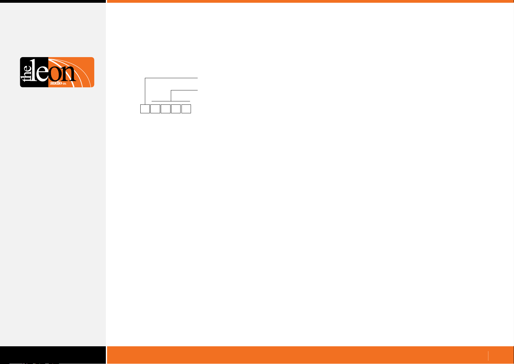
Testing
Testing the PCinterface to PC serial link
A 10 second test
•
Header
10 second test command
{
A quick test that will give the same results as the loop-back test
but without the need for the loop-back connectors.
In this test mode, you will see the following -
Both Tx & Rx lamps on the PCinterface will blink together at
•
about once per second.
On the Master A single Group A lamp will light on a channel (1-6) that
•
corresponds with the address that the Master is set to.
Every Master must be set to a different address.
Group B lamps slowly chase from channel 1 to 16.
•
Go and Standby lamps toggle for any channels that have
•
Outstations connected.
The {TEST command does not require the letter X for eXecute
to follow the command.
SET T
10 second test command
www.LeonAudio.com.au
67.
Page 68

Testing
What if it doesn’t work?
Here are a few things to check
Is the power turned on and all cables plugged in?
•
•
•
•
The Power lamp will wink about once per second.
The Tx lamp will also wink once every second as the
Heartbeat signal {RRH1 is sent out the serial port.
Is the RS232/RS485 switch in the correct position?
Output data is sent on both ports all the time.
The switch only selects which port receives data.
Try a loop-back connector.
See page 66.
Can the PC/Show Controller see the Heartbeat signal?
Connect a terminal program (such as Hyperterm etc) to
the serial port of the PCinterface and setup it up for N,8,1
with hand shaking off.
Set the terminal program to 9600 baud. If characters other
than {RRH1 are received, try other baud rates or reset the
PCinterface to 9600 baud (See page 62)
Once the PC/Show Controller can see the Heartbeat signal,
you should be able to send commands. Try the Test Comms
command on page 66. This will test the serial link to/from the
PCinterface.
If no Outstations are connected, the following commands will
turn all the Group A Lamps, on all Master Stations, on or off.
[
[
These commands must be followed by the letter X for eXecute.
Once X has been received by the PCinterface, the commands
are uploaded to the Master Station(s).
P A
0 0
0 0P0
Masters 1-6, Ch 1-16, Group A on, B off
Masters 1-6, Ch 1-16, Group A & B off
www.LeonAudio.com.au
68.
Page 69
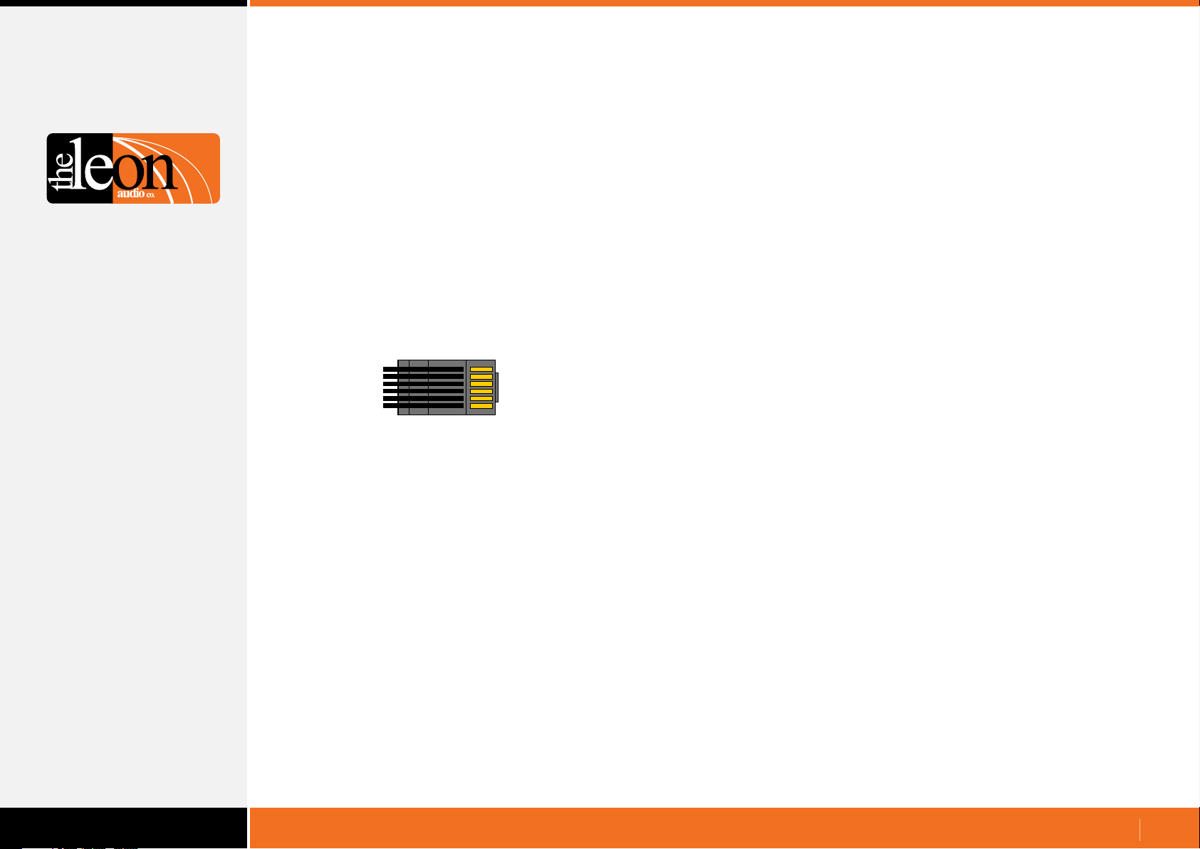
Connections
•
To/from the Cue Light Master
•
To/from the PC, Mac or Show Controller
Each Cue Light Master Station has two RJ12 Expansion Ports
wired in parallel.
The PCinterface connects to either of these Expansion Ports
via a 6 core cable fitted with RJ12 connectors.
Additional Masters, up to a total of six, can be daisy chained to
the remaining Expansion Port.
The RJ12 cable also provides power for the PCinterface from
the Cue Light Master.
The data lines in the RJ12 cable are RS485 running a
proprietary protocol.
The RJ12 cable has been tested to 100m (330 feet).
A 2m (6.5 feet) long cable is provided with the PCinterface.
The cable is of 6 core flat construction.
1
1
1 & 2 Gnd
3 Data +
4 Data 5 & 6 +30V
6
6
viewed with the latch facing away
RJ12 connector wiring
RS232 and RS485 connections are available.
Both of these connectors are optically isolated from ground to
reduce the possibility of ground loops between the PCinterface
and the equipment to which they are connected.
A switch next to the DB9 connector selects either RS232 or RS485.
Baud rates of 2400, 9600, 19200, 38400, 57600, 115200 are
supported. Data format is N81. No parity, 8 data bits and 1 stop bit.
No X-on/X-off software or hardware handshake is used.
Transmit (return monitoring) data is sent on both ports all the time.
The switch only selects which port is connected to the serial data
receiver.
The PCinterface is wired as a DCE Null Modem.
Use a standard straight through serial modem cable for connection
to the PC.
The female DB9 connector of the PCinterface unit receives data
on pin 3 and transmits data on pin 2.
Use with ‘Dual Masters’.
If the Cue Light system is running with two Master Stations
connected to the same universe, the PCinterface must be
connected to the Main Master Station.
www.LeonAudio.com.au
69.
Page 70
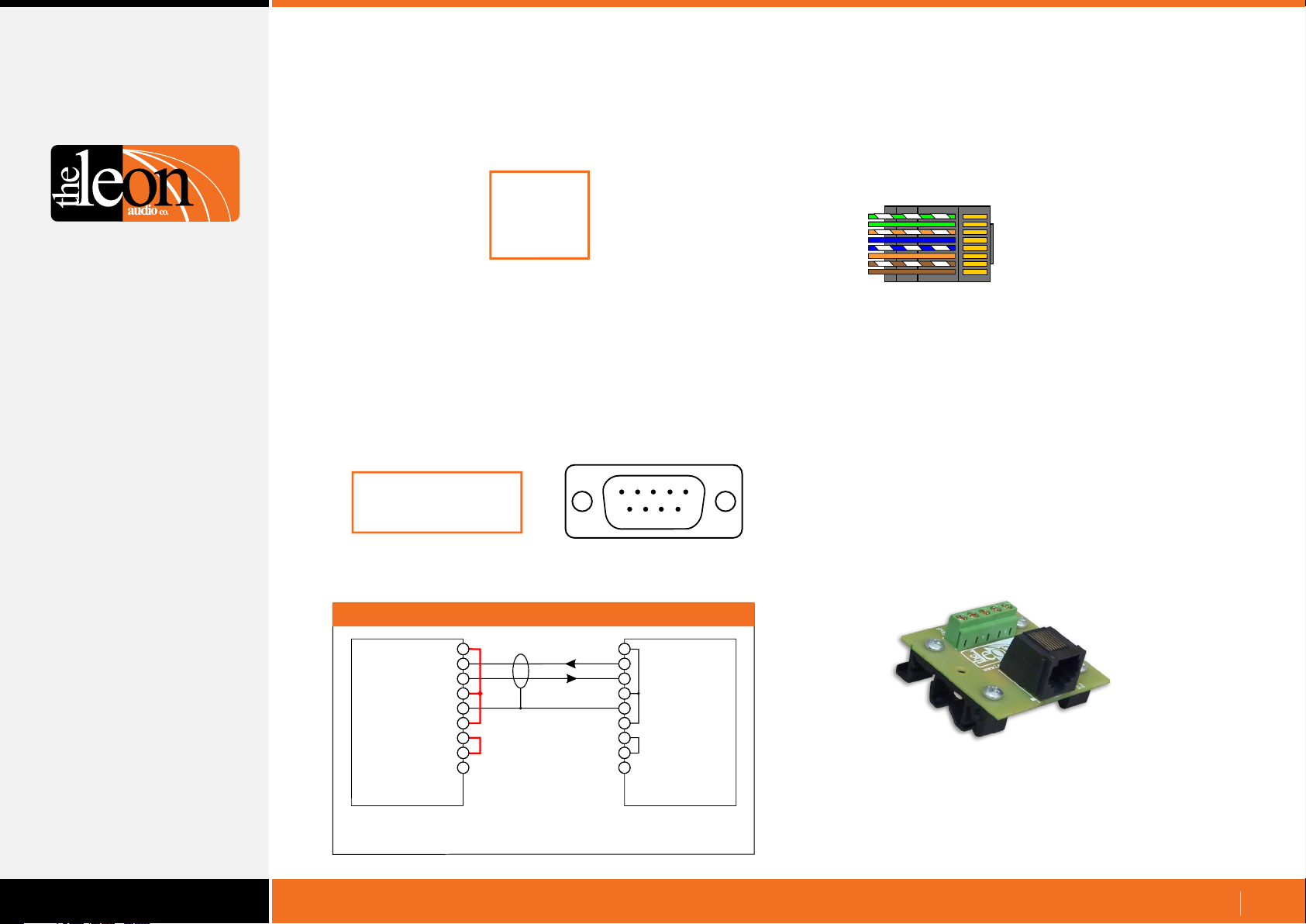
Connections
•
Computer configuration
Set the following data format and transmission rate for
RS232 or RS485
* 1 start bit
* 8 data bits
* no parity
* 1 stop bit
* 9600 baud
Baud rate can be changed once communications have been
established at 9600 baud.
The new setting is saved when the power is off.
•
RS232 Serial Cable
Use a fully wired straight through DB9 modem serial cable.
A suitable fully wired cable is supplied with the PCinterface.
Officially, the maximum length for RS232 cables is 15 metres
(50 feet), but in practice greater lengths usually work satisfactorily.
The following signals are used for data transmission.
1
2
3
4
Receive Data (RXD): Pin 3
Transmit Data (TXD): Pin 2
Signal Ground: Pin 5
5
6
7
8
9
cutout
•
RS485 Serial Connection
The RS485 RJ45 connector can be wired using CAT5/6 cable.
This cable must not be connected to any Ethernet (Internet) system.
The colours shown are only a suggestion.
Pins 4 and 5 (transmit data) must use the same coloured pair.
Pins 7 and 8 (receive data) must use the same coloured pair.
The remaining 2 pairs are Isolated ground.
1
1, 2 & 3 Isolated Gnd
4 Tx+
5 Tx6 Isolated Gnd
7 Rx+
8 Rx-
8
RJ45 (RS485) connector wiring
viewed with the latch facing away
Maximum cable length when using CAT5/6 cable is at least
1,500 metres (5,000 feet).
Two wire RS485 connections are not supported.
•
USB
PCinterface
The can be connected to a USB port using a
USB-RS232 adaptor cable. Some budget USB/RS232 cables are
not fully compliant and may not work correctly, if at all.
The “US232B 1m Converter Cable” made by FTDI have been
tested and do work correctly.
See http://www.ftdichip.com/Products/Cables/USBRS232.htm
Pin view of female DB9
If not using a fully wired cable, it should be wired as below
1
Data Input
Data Output
Ground
PC, Mac or
Show Controller
2
3
4
5
6
7
8
9
Screen
DTE DCE
The left hand connector is a DB9 on the PC/show controller.
You will need to add the wire links highlighted in red.
1
Data Output
2
Data Input
3
4
Isolated Ground
5
6
7
8
9
PCinterface
(QL-PCi Mk4)
•
RS485 Breakout Board RS485BRK
The RS485BRK Breakout Board allows connection of cables other
than CAT5/6 to the PCinterface.
The Breakout Board can be DIN rail mounted or the mounting
brackets can be removed allowing it to be installed in a project box.
There are 5 screw terminal connections. Tx+, Tx-, Rx+, Rx- and Gnd.
50mm square by 18mm high (excluding the DIN mount brackets).
www.LeonAudio.com.au
70.
Page 71
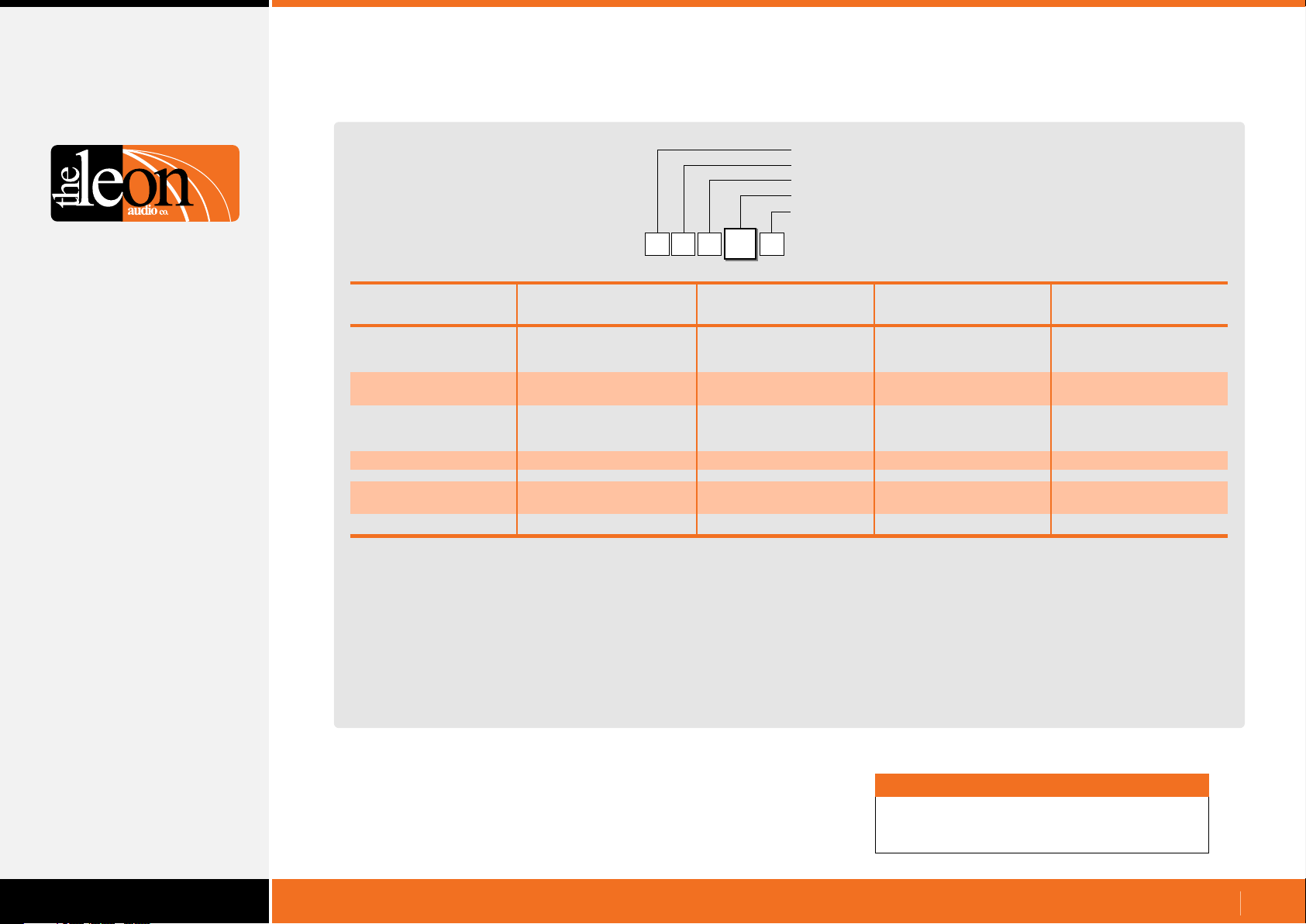
Summary of Commands
Programming Simple GUI Commands
Table of Button numbers
[
N4 1
66
Header
Master Number (0-6)
Simple GUI Command
Button Number (1-87)
Value (0=Released 1=Pressed)
A specific button on the Master Station
Channel 1 2 3 4 5 6 7 8 9 10 11 12 13 14 15 16
Touch Screen’s
Soft buttons
Group A 1 2 3 4 5 6 7 8 9 10 11 12 13 14 15 16
Group B 17 18 19 20 21 22 23 24 25 26 27 28 29 30 31 32
Master Station’s
Grey group buttons
Group Buttons 34 35 36 37 38 39 40 41 42 43 44 45 46 47 48 49
S/by Buttons 50 51 52 53 54 55 56 57 58 59 60 61 62 63 64 65
Go Buttons 66 67 68 69 70 71 72 73 74 75 76 77 78 79 80 81
Other buttons
Red Beep Button 82
White Dimmer Button 83
Group Master Buttons
Group A Standby 84
Group B Standby 85
Group A Go 86
Group B Go 87
Each horizontal row of 16 buttons (channels 1-16) uses
consecutive numbers. Number 33 is not used as it is reserved.
Note
Each number is a single byte decimal number
in the range of 1 - 87.
www.LeonAudio.com.au
71.
Page 72
Summary of Commands
Table of Cue Sheet Commands
4 G 15
Operate
Commands
Header Byte GSGO Cue
(Left square bracket)
[
Master
number Channel number
0 (Global)
15 G
1
2
3
4
5
6
0 (Global)
1
2
3
4
5
6
7
8
9
10
11
12
13
14
15
16
[
5 G 14
ASCII Dec Hex Description Description
0
1
2
3
4
5
6
7
8
9
A or (10)
B or (11)
C or (12)
D or (13)
E or (14)
F or (15)
G or (16)
Notes 1, 2
Description
Y
Z
Group A Master buttons
Group B Master buttons
1
G4
00d
01d
02d
03d
04d
05d
06d
07d
08d
09d
10d
11d
12d
13d
14d
15d
16d
Note 4
00h
01h
02h
03h
04h
05h
06h
07h
08h
09h
0Ah
0Bh
0Ch
0Dh
0Eh
0Fh
10h
[
Function
S/by Cue
C or K
Clear any Go or S/by cue
with a commandsingle
P
Channel's Group
B
Sound the Beeper Beep Duration
GSGo Master
S/by Master
154
[
G54
Value
0 or C
1 or T
0 or C
0 or K
A or (10)
B or (11)
C or (12)
D or (13)
E or (14)
F or (15)
G or (16)
Note 1
0 or C
1 or T
Clear
Trigger
Clear
A
A on, B off
B
B on, A off
C
A on, B on
D
A on, B unchanged
E
A off, B unchanged
F
B on, A unchanged
G
B off, A unchanged
A off, B off (kill)
0
5 mS (click)
1
60mS
2
120 mS
3
180 mS
4
240 mS
5
300 mS
6
360 mS
7
420 mS
8
480 mS
9
540 mS
600 mS
660 mS
720 mS
780 mS
840 mS
900 mS
960 mS
Clear
Trigger
E
Toggle
S Miscellaneous commands Q
N Note 3
Simple GUI (Number) mode 1-87d
Request Lamp Status
for all channels
F Reset Fault Lamps
Button’s number
Note 1: Double digits can be in round brackets e.g. (12)
Note 2: Multiple channels in round brackets e.g. (1,2,3) or (5-15)
Note 3: Simple GUI mode. Each button has been assigned a decimal number. See pages 8-10 for details.
Note 4: Channel number can be ASCII characters or a decimal number 00d to 16d.
Fixed value
1
Button pressed
1
Button released
0
www.LeonAudio.com.au
72.
Page 73
Summary of Configuration Commands
Overview of Functions
(
Function
A
Outstation
B
S/by Flash on Master
C
S/by Flash on Outstation
D
S/by latches
E
S/by Dims on ACK
Outstation Go Flickers
F
Go times out
G
Go flashes
H
Go latches
J
Go & S/by interlocked
K
Call lamp enabled
M
Call lamp flashes
N
ACK button back-light
P
Beeper enable
Q
Beep-on-Go
R
Change colour on ACK
S
Dimmer
T
Cue Light Outstation Functions
Upper Case
S/by colour
{
)
5
1
Factory
Default
Yellow
Flashes
Flashes
Latches
No
Steady
Times out
Flashes
Latches
Interlocked
Enabled
Flashes
On
Enabled
Silent
No change
100%
A
1
User Selectable
Function
Red
Steady
Steady
Momentary
Dims on ACK
Flickers
Stays on
Steady
Momentary
Independent
Call lamp off
Steady
Off
Disabled
Beeps (4 choices)
Change colour
5-100% in 5 steps
Function
1
Unsafe Lamp
2
Safe when... open/closed
3
End Of Line Resistors
4
All Lamps on Outstation
Sensor Outstation Functions
Function
A
Copy 1 of 8 files to PC
B
Copy 1 of 7 files to the
C
E
F
ShowTime file.
Copy ShowTime file to
Installer's Default
or 1 of 4 User files.
Go Cue Total Duration
Link 4 Group Master buttons
Factory
Default
Steady
Open
No EOL
Enabled
Factory
Default
15 Secs
Linked
User Selectable
Function
Flash
Closed
Two EOL
Disabled
User Selectable
Function
1-16 Secs
Not Linked
Function Lower Case
a
Mode
b
S/by Flash on Master
c
S/by Flash on Outstation
d
S/by latches
e
Go times out
f
Go flashes
g
Go latches
h
Go & S/by interlocked
j
Call lamp enabled
k
Call lamp Flashes
m
All Lamps on Outstation
Relay Outstation Functions
(
)
Factory
Default
Flashes
Flashes
Latches
Times out
Flashes
Latches
Interlocked
Enabled
Flashes
Enabled
User Selectable
Function
5 modes
Steady
Steady
Momentary
Stays on
Steady
Momentary
Independent
Call lamp off
Steady
Off
Master Station Functions
Function
R
Monitoring Reply Mode
B
Baud Rate
H
Heart Beat @ 1Hz rate
P
T
PCinterface Functions
(Idle Character)
Pacing. Pause between
each 5 byte reply
Terminator chx for replies
Values
Simple GUI Reply
or Channel & Function Reply
2400 to 115200
on/off
0uS, 100uS, 300uS, 1mS,
3mS, 10mS, 30mS
None } | <space> <LF> ~
www.LeonAudio.com.au
73.
Page 74
Summary of Configuration Commands
Table of Cue Light Outstation Configuration Commands
A
1
{
Configuration
Commands
Header Byte
(Left curly bracket)
{
15
1
15 A
5 A 1
1{A1
{
151
{
A51
Master
number Channel number
ASCII Dec Hex Description Description
0 (Global)
1
2
3
4
5
6
0 (Global)
1
2
3
4
5
6
7
8
9
10
11
12
13
14
15
16
0
1
2
3
4
5
6
7
8
9
A or (10)
B or (11)
C or (12)
D or (13)
E or (14)
F or (15)
G or (16)
Note 1
00d
01d
02d
03d
04d
05d
06d
07d
08d
09d
10d
11d
12d
13d
14d
15d
16d
Note 2
00h
01h
02h
03h
04h
05h
06h
07h
08h
09h
0Ah
0Bh
0Ch
0Dh
0Eh
0Fh
10h
Function
Outstation’s Standby Colour
A
Standby Flash on Master
B
Standby Flash on Outstation
C
Standby Latches
D
Standby DIMs on Acknowledge
E
Outstation Go Flickers
F
Go Times-out
G
Go Flashes
H
Go Latches
J
Go & S/by Interlocked
K
0 or R
1 or Y
0 or S
1 or F
0 or M
1 or F
0 or N
1 or D
0 or S
1 or F
0 or N
1 or T
0 or S
1 or F
0 or M
1 or L
0
1
Value
Red
Yellow
Steady
Flash
Momentary
Latches
No DIM on ACK
DIM on ACK
Steady
Flicker
No time-out
Times-out after delay
Steady
Flashes after 3 secs.
Momentary
Latches
Independent
Interlocked
Note 1:
Double digits can be in round brackets e.g. (12)
Multiple channels in round brackets e.g. (1,2,3) or (5-15)
Note 2: Channel number can be a decimal number 00d to 16d
or ASCII characters.
Call Lamp Enabled
M
Call lamp Flashes
N
Acknowledge button backlight
P
Beeper Enable
Q
Beep-On-Go
R
S/by Change Colour on ACK
S
Dimmer
T
This Column is Upper Case
0 or D
1 or E
0 or S
1 or F
0 or F
1 or N
0
1
2
3
0 or N
1 or C
1
2
3
4
5
Disabled
Enabled
Steady
Flashes
ofF
oN
Off
1mS
50mS
200mS
No Colour Change
Change Colour
5%
25%
50%
75%
100%
www.LeonAudio.com.au
74.
Page 75
Summary of Configuration Commands
Table of Relay Outstation Configuration Commands
1 15
{
Configuration
Commands
Header Byte
(Left curly bracket)
{
1
15 bb
5 b 1
Master
number Channel number
ASCII Dec Hex Description Description
0 (Global)
1
2
3
4
5
6
0 (Global)
1
2
3
4
5
6
7
8
9
10
11
12
13
14
15
16
0
1
2
3
4
5
6
7
8
9
A or (10)
B or (11)
C or (12)
D or (13)
E or (14)
F or (15)
G or (16)
Note 1
1{b1
00d
01d
02d
03d
04d
05d
06d
07d
08d
09d
10d
11d
12d
13d
14d
15d
16d
Note 2
00h
01h
02h
03h
04h
05h
06h
07h
08h
09h
0Ah
0Bh
0Ch
0Dh
0Eh
0Fh
10h
{
Function
Mode
a
S/by Flash on Master
b
S/by Flash on Outstation
c
S/by latches
d
Go times out
e
Go flashes
f
Go latches
g
Go & S/by interlocked
h
151
{
b51
Value
1
2
3
4
5
0 or S
1 or F
0 or S
1 or F
0 or M
1 or L
0 or N
1 or T
0 or S
1 or F
0 or M
1 or L
0
1
A: Mom B: Mom
A: Latch B: Latch
A: Mom B: Latch
A: Latch B: Mom
Cue Light Mode
Steady
Flashes
Steady
Flashes
Momentary
Latches
No time-out
Times-out after delay
Steady
Flashes after 3 secs.
Momentary
Latches
Independent
Interlocked
Note 1:
Note 2: Channel number can be ASCII characters or a decimal number 00d to 16d.
Double digits can be in round brackets e.g. (12)
Multiple channels in round brackets e.g. (1,2,3) or (5-15)
Call lamp enabled
j
Call lamp Flashes
k
All Lamps on Outstation
m
This Column is Lower Case
0 or D
1 or E
0 or S
1 or F
0 or D
1 or E
Disabled
Enabled
Steady
Flashes
Disabled
Enabled
www.LeonAudio.com.au
75.
Page 76
Summary of Configuration Commands
Table of Sensor Outstation Configuration Commands
3
1 15
{
Configuration
Commands
Header Byte
(Left curly bracket)
Note 1:
Note 2: Channel number can be ASCII characters or a decimal number 00d to 16d.
Double digits can be in round brackets e.g. (12)
Multiple channels in round brackets e.g. (1,2,3) or (5-15)
{
1
15 3
5 3 1
Master
number Channel number
ASCII Dec Hex Description Description
0 (Global)
1
2
3
4
5
6
0 (Global)
1
2
3
4
5
6
7
8
9
10
11
12
13
14
15
16
0
1
2
3
4
5
6
7
8
9
A or (10)
B or (11)
C or (12)
D or (13)
E or (14)
F or (15)
G or (16)
Note 1
1{31
00d
01d
02d
03d
04d
05d
06d
07d
08d
09d
10d
11d
12d
13d
14d
15d
16d
Note 2
00h
01h
02h
03h
04h
05h
06h
07h
08h
09h
0Ah
0Bh
0Ch
0Dh
0Eh
0Fh
10h
{
Function
Unsafe Lamp
1
Safe when... open/closed
2
End Of Line Resistors
3
4
All Lamps on Outstation
151
{
351
Value
0 or S
1 or F
0 or O
1 or C
0 or N
1 or T
0 or D
1 or E
Steady
Flashes
Open
Closed
No EOL
two EOL
Disabled
Enabled
www.LeonAudio.com.au
76.
Page 77
Summary of Configuration Commands
Table of Master Station Configuration Commands
E
M
1
{
Configuration
Commands
Header Byte
(Left curly bracket)
{
6
1
6M E
M
6{E1
{
6M1
E 6
{
EM1
Master
number Master Config
M Fixed value0 (Global)
1
2
3
4
5
6
Function
Description Description
Copy 1 of 8 files to PC
A
Copy 1 of 7 files to ShowTime file
B
Copy ShowTime file to Installer's Default
C
or 1 of 4 User files.
Go Cue Total Duration (1 to 16 seconds)
E
0
1
2
3
4
5
6
7
0
1
2
3
4
6
7
0
1
2
3
4
1 to 9
A or (10)
B or (11)
C or (12)
D or (13)
E or (14)
F or (15)
G or (16)
Value
Installer's Default file
User file 1
User file 2
User file 3
User file 4
ShowTime file
Factory default (red S/by)
Factory default (yellow S/by)
Installer's Default file
User file 1
User file 2
User file 3
User file 4
Factory default (red S/by)
Factory default (yellow S/by)
Installer's Default file
User file 1
User file 2
User file 3
User file 4
1 to 9 seconds
10 seconds Note 1
11 seconds
12 seconds
13 seconds
14 seconds
15 seconds
16 seconds
Note 1: Double digits can be in round brackets e.g. (12)
Link the 4 Group Master buttons between
F
multiple Masters
0
1
Not linked
Linked
www.LeonAudio.com.au
77.
Page 78
Summary of Configuration Commands
Table of PCinterface Configuration Commands
R 5
C
{
Configuration
Commands
Header Byte
(Left curly bracket)
{
R
PCinterface
( )
fixed value
5C BB
C B 5
5{BR
{
5CR
{
PCinterface
( )
fixed value
CR
R
B
H
P
T
Function
Description Description
Monitoring Reply Mode
Baud Rate
Heart Beat Signal
Reply Pacing. Pause between
each 5 byte reply
Terminator chx for replies
0
1
0
1
2
3
4
5
0
1
0
1
2
3
4
5
6
0
1
2
3
4
5
BCR
Value
Simple GUI Reply
Channel & Function Reply with
all ASCII characters.
2400 baud
9600 baud
19200 baud
38400 baud
57600 baud
115200 baud
Off
On
0uS
100uS
300uS
1mS
3mS
10mS
30mS
none
} 7Dh
| 7Ch
space 20h
line feed 0Ah
~ 7Eh
www.LeonAudio.com.au
78.
Page 79
Return Monitoring
Simple GUI Reply format
Table of Lamp numbers
[
1
92
A specific lamp on the Master Station
1N
Channel 1 2 3 4 5 6 7 8 9 10 11 12 13 14 15 16
Fault Lamp 1 2 3 4 5 6 7 8 9 10 11 12 13 14 15 16
Group A Lamp 17 18 19 20 21 22 23 24 25 26 27 28 29 30 31 32
Group B Lamp 34 35 36 37 38 39 40 41 42 43 44 45 46 47 48 49
Call lamp 50 51 52 53 54 55 56 57 58 59 60 61 62 63 64 65
S/by Lamp 66 67 68 69 70 71 72 73 74 75 76 77 78 79 80 81
Go Lamp 92 93 94 95 96 97 98 99 100 101 102 103 104 105 106 107
Sensor Lamps
Fault 108 109 110 111
Unsafe 112 113 114 115
Safe 116 117 118 119
Other Lamps
Group A Master Lamps 82 (S/by & Go buttons light as a pair)
Group B Master Lamps 83 (S/by & Go buttons light as a pair)
Short Lamp 84
Aux lamp 85 (not fitted)
Each horizontal row of 16 lamps (channels 1-16) uses consecutive
numbers. Numbers 86 through 91 are not used as they are reserved.
Header
[
1
N
92
1
Simple GUI Reply format
Master Number (1-6)
Simple GUI Reply
Lamp Number (1-119)
Value (0-3)
Value
0
1
2
3
Lamp
Off
On
Flashing
Dimmed
Note
Each number is a single byte decimal number
in the range of 1 - 119.
www.LeonAudio.com.au
79.
Page 80
Return Monitoring
Table of Return Monitoring. Channel & Function format
1 G 15
Operate
Replies
Header Byte
(Left square bracket)
[
1
15 G
5 G 1
Master
number Channel number
ASCII
1
2
3
4
5
6
1
2
3
4
5
6
7
8
9
10
11
12
13
14
15
16
Sensor 1
Sensor 2
Sensor 3
Sensor 4
Other Lamps
1[G1
[
151
Function
ASCII Description Description
1
2
3
4
5
6
7
8
9
A
B
C
D
E
F
G
T
U
V
W
S
F
Fault Lamps
A
Group A Lamps
B
Group B Lamps
Call Lamps
C
Standby Lamps
S
Go Lamps
G
Fault Lamps
F
Unsafe Lamps
U
S
Safe Lamps
A
Group A Master
B
Group B Master
S
Short Lamp
Aux Lamp (not fitted)
T
[
G51
Value
0
1
2
0
1
0
1
0
1
2
0
1
2
3
0
1
2
3
0
1
2
0
1
2
0
1
0
3
0
3
0
1
0
1
Off
On
Flash
Off
On
Off
On
Off
On
Flash
Off
On
Flash
Dimmed
Off
On
Flash
Dimmed
Off
On
Flash
Off
On
Flash
Off
On
Off
Dimmed
Off
Dimmed
Off
On
Off
On
www.LeonAudio.com.au
80.
Page 81
ASCII Character Codes
Dec Hex Chx Dec Hex Chx Dec Hex Chx Dec Hex Chx
000 000 NUL 032 020 Space 064 040 @ 096 060 `
001 001 SOH 033 021 ! 065 041 A 097 061 a
002 002 STX 034 022 " 066 042 B 098 062 b
003 003 ETX 035 023 # 067 043 C 099 063 c
004 004 EOT 036 024 $ 068 044 D 100 064 d
005 005 ENQ 037 025 % 069 045 E 101 065 e
006 006 ACK 038 026 & 070 046 F 102 066 f
007 007 BEL 039 027 ' 071 047 G 103 067 g
008 008 BS 040 028 ( 072 048 H 104 068 h
009 009 HT 041 029 ) 073 049 I 105 069 I
010 00A LF 042 02A * 074 04A J 106 06A j
011 00B VT 043 02B + 075 04B K 107 06B k
012 00C FF 044 02C , 076 04C L 108 06C l
013 00D CR 045 02D - 077 04D M 109 06D m
014 00E SO 046 02E . 078 04E N 110 06E n
015 00F SI 047 02F / 079 04F O 111 06F o
016 010 DLE 048 030 0 080 050 P 112 070 p
017 011 DC1 049 031 1 081 051 Q 113 071 q
018 012 DC2 050 032 2 082 052 R 114 072 r
019 013 DC3 051 033 3 083 053 S 115 073 s
020 014 DC4 052 034 4 084 054 T 116 074 t
021 015 NAK 053 035 5 085 055 U 117 075 u
022 016 SYN 054 036 6 086 056 V 118 076 v
023 017 ETB 055 037 7 087 057 W 119 077 w
024 018 CAN 056 038 8 088 058 X 120 078 x
025 019 EM 057 039 9 089 059 Y 121 079 y
026 01A SUB 058 03A : 090 05A Z 122 07A z
027 01B ESC 059 03B ; 091 05B [ 123 07B {
028 01C FS 060 03C < 092 05C \ 124 07C |
029 01D GS 061 03D = 093 05D ] 125 07D }
030 01E RS 062 03E > 094 05E ^ 126 07E ~
031 01F US 063 03F ? 095 05F _ 127 07F DEL
www.LeonAudio.com.au
81.
Page 82

62 Edgewar
South Australia, 5154
Phone: 08 8339 3865
Mobile: 0419 826 262
International
Phone: +61 8 8339 3865
Mobile: +61 419 826 262
www.LeonAudio.com.au
Email Us
e Road, Aldgate,
Specifications
Cue Light PCinterface
Model Ql-PCi mk4
Connectors
To PC/Show controller:
RS232 9 pin DB9
RS485 8P8C RJ45
Both RS232 and RS485 ports are opto-isolated
To Cue Light Master’s Expansion Port:
6P6C RJ12
Power
Powered via RJ12 from the Cue Light Master
Dimensions
Width: 92mm (3.7”)
Length (excluding connectors): 148mm (5.8”)
Height: 38mm (1.5”)
Weight
515g (1.14 lbs)
Warranty
The Leon Audio for Cue Light System is guaranteed for five years from date of original purchase against defects in workmanship
and materials. If suc
prepaid to THE LEON AUDIO COMPANY. Unit will be returned prepaid. Warranty does not cover finish or malfunction due to abuse or operation
at other than specified conditions. Repairs by other than THE LEON AUDIO COMPANY or authorized agents will void this guarantee.
PCinterface
www.LeonAudio.com.au
1/18
Rev 2.53
82.
 Loading...