

Page 1
1.1. Rotary Cam Switch GSW100
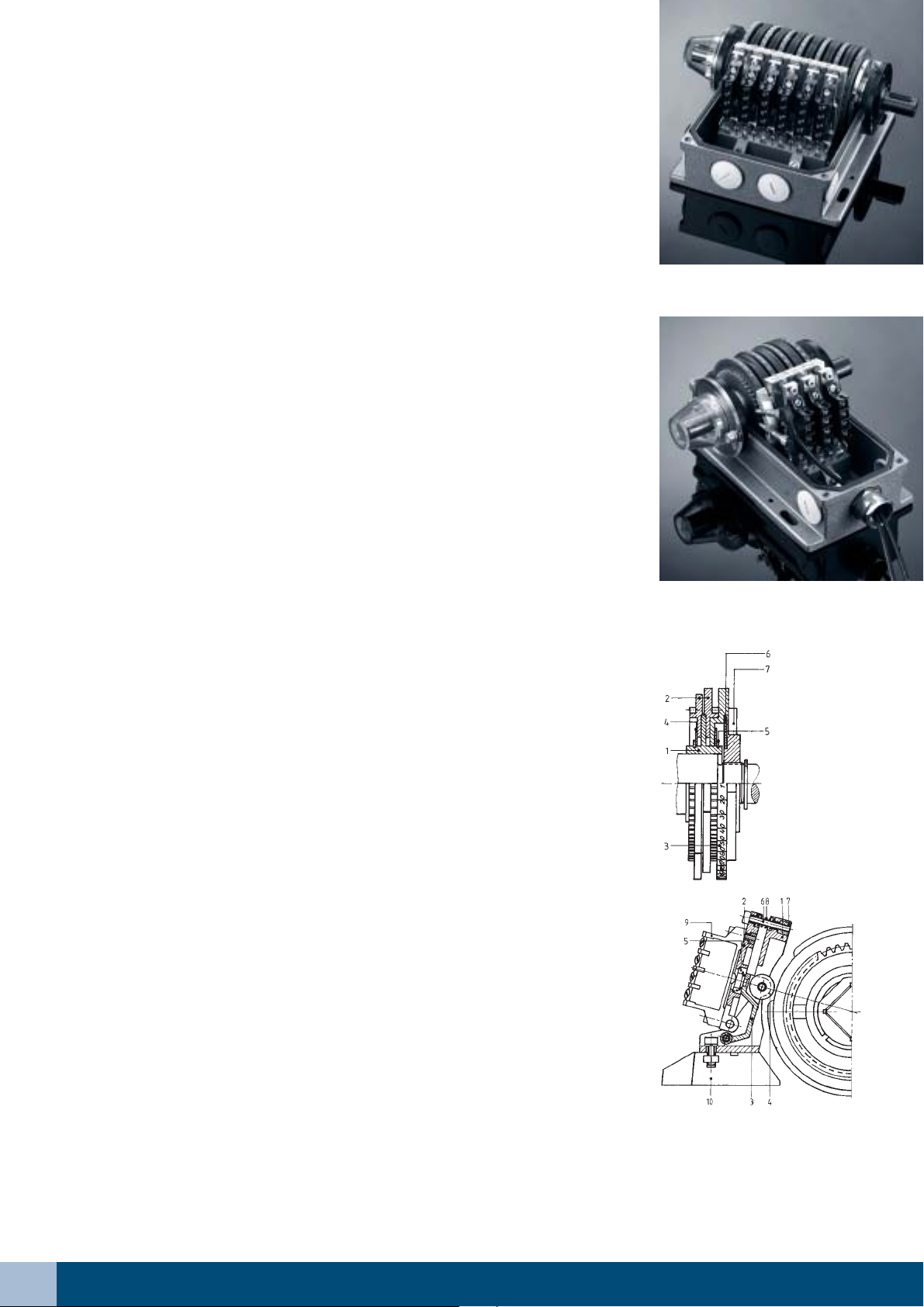
LEONARD rotary cam switches GSW100 (see figure 1.1.1 and 1.1.2) are cased in
housings made of cast aluminum and fitted out with mechanic switching elements.
The technical data of all available switching elements are listed in figure 1.0.1.
The rotary cam switches GSW100 are normally available with 3, 6, 9, 12, 15 and
20 switching elements. The cam shaft (spindle) comes out on both sides of the
housing so that several switches can be coupled together. The second end of the
shaft, which is normally unused, is protected by a safety cover. The transparent
safety cover has some index marks for the scale ring underneath. The cam shaft
is mounted in two deep groove ball bearings and maintenance-free.
To actuate the individual switching elements the cam shaft is fitted with cam disk
sets in a pitch of 20 mm (see figure 1.1.5). Each cam disk set consists of the
components listed in figure 1.1.3.
The infinitely adjustable cam disk sets, which run almost entirely free from
unbalance by virtue of their special design, are individually tensioned by disc
springs. This tension is such that all cam disk sets can be adjusted when the
clamp nut is slackened. After setting all the cam disk sets the complete adjustment
can be checked on start up for trial operation. Only after all switching adjustments
have been tested, the clamp nut is tightened against the disc spring. All cam disk
sets are positively located in the position set.
Fig. 1.1.1: Rotary Cam Switch
GSW100-06 MNS without Cover
The normal cam rings have 180° long cams. For switching elements with force
separation the cam rings are available with cam length of 15°, 30°, 45° or 90°.
For the application from rotary cam switches on presses our switches are
optionally available with an additional clamping device. In this case, after all
adjustments have been carried out, the clamping element of each cam disk set is
tightened against the cam disk set by turning the clamping screw clockwise form
underneath. When the cam disk sets have been locked in this way they cannot be
moved out of position even though the clamp nut is slackened and the preliminary
tension has got over. The cam disk sets can be permanently secured to prevent
unintentional or unauthorized adjustment by additionally caulking the clamping
screw slots.
The cam rings and graduated disks have a diameter of 100 mm and a scale of
360° with a graduation of 2°, though a high and precise switching angle resolution
is provided. The accurate adjustment of the switching points is guaranteed,
because the cam rings have a switch-on and switch-off point index mark. The
cam rings as well as the graduated disks are made of die-cast aluminum. Thus
reduces the inertia forces and increases the life of the deep groove ball bearings.
Based on the surface protection of the cam rings and the graduated disks, they
are “hard coated”, a maximum of surface hardness, a maximum of corrosion
protection and a maximum of resistance to seawater and many chemical
substances is guaranteed.
All parts of the switching element actuator (see figure 1.1.4) are of zinc die-casting
and surface traded or of acid-resisting stainless steel. The roller is produced from
wear-resistant plastic and is self lubricating. The rotary cam switches dispose of
ideal anti-friction properties. Therefore the wear of the rollers in the roller levers
is reduced to a minimum.
GSW100
Fig. 1.1.2:
Presses Safety Cam Switch
GSW100-03 MNS-2PI without Cover
Fig. 1.1.3:
Cam Disk Set
GSW100
1 = carrier disk
2 = cam rings
3 = graduated disk
4 = plate spring
5 = retainer ring
6 = clamp spring
7 = clamp nut
Fig. 1.1.4:
Switching Element Actuator GSW100
1 = bracket 6 = adjusting screw
2 = contact holder 7 = self-locking nut
3 = roller lever 8 = compression spring
4 = roller 9 = switching element
5 = return spring 10 = contact strip
– 8 –1.1
Page 2

The housing of the rotary cam switch is made of aluminum alloy and painted in RAL6011. Optional the switch
can be supplied in a seawaterproof performance. The housing is divided into the bottom section and the top
section at the spindle centre. Both parts are eternal connected by hinges and screws of stainless steel. The rotary
cam switch could be mounted with 4 screws M8. Please have a look at all dimensions in figure 1.1.6 and figure
1.1.7.
For driving the LEONARD rotary cam switch GSW100 the gearbox GV is suitable.
Fig. 1.1.5:
Cam Shaft
GSW100-03
left right
Fig. 1.1.6: Dimensioned Drawing GSW100
Fig. 1.1.7: Table of Dimensions GSW100 (without gear)
type number of A B C D weight
cable entries M32 [mm] [mm] [mm] [mm] [kg]
GSW100-03 3 105 124 114 184 4,0
GSW100-06 4 165 184 174 249 6,5
GSW100-09 5 225 244 234 309 9,5
GSW100-12 6 285 304 294 369 12,0
GSW100-15 7 370 390 380 455 15,5
GSW100-20 8 483 503 492 576 20,0
– 9 – 1.1
Page 3

Ordering instructions for type GSW100:
type number of type of gearbox ratio drive side
switching switching (input)
elements elements
*0)*
1
)*
Product overview:
GSW100- 03 MNS [no statement] [no statement] [no statement]
06 MNSG GV Have a look l [left side]
09 MNST at the technical r [right side]
12 RD data of our
15 gearboxes!
20
Example:
GSW100-06 MNS GV 175:1 l
*1) If the rotary cam switch is not fitted out with the complete number of switching elements, we need the
max. possible number of switching elements. The actually fitting must be described “in plain text”!
*2)We don’t need this information for a rotary cam switch without a gearbox.
*3) If this information is missing, the input is on the right side of the switch.
2
)*
2
)*
3
)
If you need a rotary cam switch with different switching elements or a switch in a special design,
please give a precise description “in plain text”!
– 10 –1.1
 Loading...