

Page 1

CMVCAN01A
SMVector - CANopen Communication Module
Communications Interface Reference Guide
Page 2

This documentation applies to the CANopen communications option for the SMVector inverter and
should be used in conjunction with the SMVector Operating Instructions (Document SV01) that
shipped with the drive. These documents should be read carefully as they contain important technical
data and describe the installation and operation of the drive and this option.
© 2007 AC Technology Corporation
No part of this documentation may be copied or made available to third parties without the explicit
written approval of AC Technology Corporation.
All information given in this documentation has been carefully selected and tested for compliance with
the hardware and software described. Nevertheless, discrepancies cannot be ruled out. We do not
accept any responsibility nor liability for damages that may occur. Any necessary corrections will be
implemented in subsequent editions.
About these instructions
Page 3

1 Safety information ................................................................2
2 Introduction ..........................................................................4
2.1 Overview ...................................................................................................4
2.2 SMVector CANopen Implementation Specifications ...................................4
3 Installation ............................................................................5
3.1 Installing the Module into the Terminal Cover ..........................................5
3.2 CANopen terminal block ...........................................................................5
3.3 Installing the Terminal Cover ....................................................................6
4 Commissioning CANopen communications .....................7
4.1 Quick Set-up .............................................................................................7
5 Extended Parameters for CANopen ...................................8
5.1 Parameter menu .......................................................................................8
5.2 CANopen mapping details .....................................................................17
5.2.1 RPDO mapping details (P446/P456) ......................................................17
5.2.2 TPDO mapping details (P466/P476) .......................................................20
6 Troubleshooting and fault elimination .............................23
6.1 Faults ......................................................................................................23
6.2 Troubleshooting ......................................................................................
23
A1 Appendix A - Configuration Example ...............................24
A1.1 Master / Follower drive system ...............................................................24
1
ENGLISH
Contents
Page 4

2
ENGLISH
Safety information
1 Safety information
General
Some parts of Lenze controllers (frequency inverters, servo inverters, DC controllers) can be live,
moving and rotating. Some surfaces can be hot.
Non-authorized removal of the required cover, inappropriate use, and incorrect installation or operation
creates the risk of severe injury to personnel or damage to equipment.
All operations concerning transport, installation, and commissioning as well as maintenance must
be carried out by qualified, skilled personnel (IEC 364 and CENELEC HD 384 or DIN VDE 0100 and
IEC report 664 or DIN VDE0110 and national regulations for the prevention of accidents must be
observed).
According to this basic safety information, qualified skilled personnel are persons who are familiar with
the installation, assembly, commissioning, and operation of the product and who have the qualifications
necessary for their occupation.
Application as directed
Drive controllers are components which are designed for installation in electrical systems or machinery.
They are not to be used as appliances. They are intended exclusively for professional and commercial
purposes according to EN 61000-3-2. The documentation includes information on compliance with
the EN 61000-3-2.
When installing the drive controllers in machines, commissioning (i.e. the starting of operation as
directed) is prohibited until it is proven that the machine complies with the regulations of the EC Directive
98/37/EC (Machinery Directive); EN 60204 must be observed.
Commissioning (i.e. starting of operation as directed) is only allowed when there is compliance with
the EMC Directive (89/336/EEC).
The drive controllers meet the requirements of the Low Voltage Directive 73/23/EEC. The harmonised
standards of the series EN 50178/DIN VDE 0160 apply to the controllers.
The availability of controllers is restricted according to EN 61800-3. These products can cause
radio interference in residential areas. In this case, special measures can be necessary.
Installation
Ensure proper handling and avoid excessive mechanical stress. Do not bend any components and
do not change any insulation distances during transport or handling. Do not touch any electronic
components and contacts.
Controllers contain electrostatically sensitive components, which can easily be damaged by inappropriate
handling. Do not damage or destroy any electrical components since this might endanger your
health!
Electrical connection
When working on live drive controllers, applicable national regulations for the prevention of accidents
(e.g. VBG 4) must be observed.
The electrical installation must be carried out according to the appropriate regulations (e.g. cable crosssections, fuses, PE connection). Additional information can be obtained from the documentation.
The documentation contains information about installation in compliance with EMC (shielding, grounding,
filters and cables). These notes must also be observed for CE-marked controllers.
The manufacturer of the system or machine is responsible for compliance with the required limit values
demanded by EMC legislation.
Operation
Systems including controllers must be equipped with additional monitoring and protection devices
according to the corresponding standards (e.g. technical equipment, regulations for prevention
of accidents, etc.). You are allowed to adapt the controller to your application as described in the
documentation.
Page 5

3
ENGLISH
Safety information
DANGER!
• After the controller has been disconnected from the supply voltage, live components
and power connection must not be touched immediately, since capacitors could be
charged. Please observe the corresponding notes on the controller.
• Do not continuously cycle input power to the controller more than once every three
minutes.
• Please close all protective covers and doors during operation.
WARNING!
Network control permits automatic starting and stopping of the inverter drive. The
system design must incorporate adequate protection to prevent personnel from
accessing moving equipment while power is applied to the drive system.
Pictographs used in these instructions
Pictograph Signal word Meaning Consequences if ignored
DANGER!
Warning of Hazardous
Electrical Voltage.
Reference to an imminent
danger that may result in death
or serious personal injury if the
corresponding measures are not
taken.
WARNING!
Impending or possible danger
for persons
Death or injury
STOP!
Possible damage to equipment
Damage to drive system or its
surroundings
Note
Useful tip: If observed, it will
make using the drive easier
Page 6

2 Introduction
This reference guide assumes that the reader has a working knowledge of CANopen
Fieldbus Protocol and familiarity with the programming and operation of motion control
equipment. This guide is intended as a reference only.
2.1 Overview
CANopen Fieldbus is an internationally accepted communications protocol designed for
commercial and industrial installations of motion control applications. High data transfer
rates combined with it’s efficient data formatting permit the coordination of motion control
devices in multi-axis applications. AC Tech’s implementation of the CANopen protocol
allows for baud rates ranging from 10 kbps to 1Mbps.
DSP402 compatible control and status words are available to the user for configuring
modes of operation and altering the drive operating parameters. Additionally, to offer
greater interoperability with the SMVector inverter, a drive specific set of objects are
available that offer further drive profile configuration and allow access to specific modes of
operation.
2.2 SMVector CANopen Implementation Specifications
• Supported data rates (bit/s): 1.0M, 800K, 500K, 250K, 125K, 50K, 20K, 10K.
• 2 transmit and 2 receive process data objects (PDOs) supported.
• Synchronous, Asynchronous and Change of State PDO communications modes
supported.
• Two Service Data Objects (SDO) provide access to all SMV parameters
• Heartbeat and Node guarding with selectable timeout action
• DSP402 compatible Control and Status Words accessible via PDO and SDO.
To simplify the setup of the CANopen Master, AC Tech will provide the applicable EDS
(Electronic Data Sheet).
4
ENGLISH
Introduction
Page 7

5
ENGLISH
Installation
3 Installation
3.1 Installing the Module into the Terminal Cover
7mm
<_ 2.8 mm²
(12-22 AWG)
0.5 Nm/ 4.5 lb-in
1 2 3 4 5
3.2 CANopen terminal block
Terminal Description Important
1 CAN_GND: CAN earth ground
For reliable communication make sure terminal
CAN_GND is connected to CAN network
GND/common. If only two wires are used (CAN_H
and CAN_L) in the network, connect CAN_GND to
chassis/earth ground.
2 CAN_L: CAN low
If controller is located at either end of the network,
a terminating resistor (120ohm typical) should be
connected across CAN_L and CAN_H
3
4 CAN_H: CAN high
5
Protection against contact
• All terminals have basic isolation (single insulating distance)
• Protection against contact can only be ensured by additional measures (i.e. double insulation)
Page 8

6
ENGLISH
Installation
3.3 Installing the Terminal Cover
Page 9

7
ENGLISH
Commissioning
4 Commissioning CANopen communications
Following installation of the CANopen communications module,
4.1 Quick Set-up
With drive power disconnected connect the CANopen communication module and
network cable to the drive as shown in the preceding section.
NOTE:
If CANopen network is already operational do NOT connect the network connector
until the Node ID and Baud rate parameters on installed drive are setup correctly.
Apply Power to the drive. In drive parameter menu, select parameter P400 Network
Protocol and set it to 3 -- CANopen. After this action, the module will be initialized with
CANopen protocol and will enter Online mode - P402 = 3.
To monitor and control the drive via network, the following parameters should be set as a
minimum:
P410 Node Id (default 1)
P411 Baud Rate (default 5 = 500 kbps)
P100 Start Control Source - Network control can be taken in any mode of operation except when
P100 = 2 Remote Keypad Only.
NOTE:
If P100 is not equal 0, TB1 must be connected to TB4 in order to start the drive.
P112 Rotation - Set this parameter to Forward and Reverse (1) if operation in both directions is
required.
P121
P122
or
P123
One of these parameters must be set to 9 - Network Enable and corresponding terminal
must be closed in order to take network control and start via network.
P304 Motor Rated frequency, P305 Motor Rated Speed - if Network speed needs to be scaled in
RPMs units; those parameters must be set accordingly to motor nameplate.
To activate changes made to P400 and P401 use P418 Reset CAN node parameter or
recycle the power.
If no other CANopen parameter has been modified the drive will enter CANopen Preoperational state (see P412, P419) and every 2 seconds (P416) will transmit a heartbeat
message.
As a default, RPDO#1 (P44x) and TPDO#1 (P46x) are active when the CANopen state is
switched to the operational state.
Page 10
8
ENGLISH
Commissioning
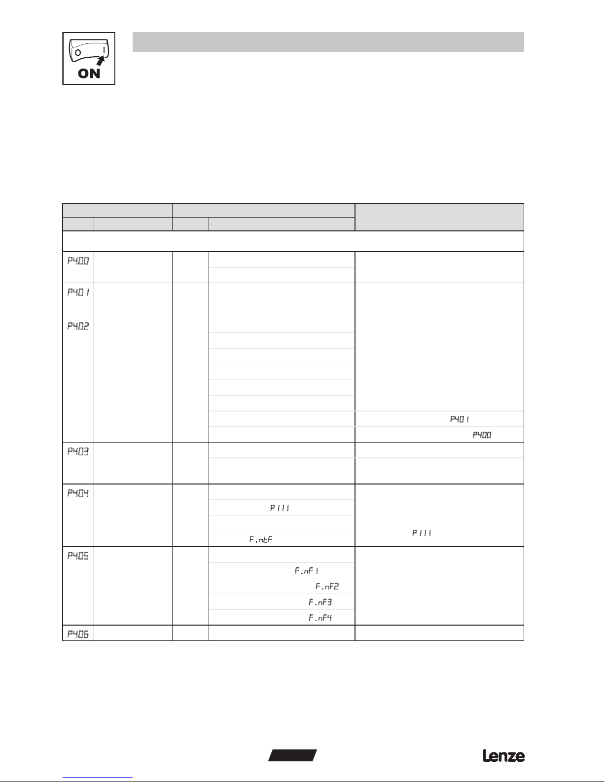
5 Extended Parameters for CANopen
In addition to the drive parameters (detailed in the Installation and Operation manual that
accompanied the drive), the installation of the CANopen module will give access to the
400 series parameters that are exclusively for the CANopen communications module.
5.1 Parameter menu
Code Possible Settings
IMPORTANT
No. Name Default Selection
CANopen Module Specific parameters
p400
Network Protocol
0 Not Active
3 CANopen
P401
Module Revision 02.0.0 Display reads 02.x.x where:
02 = CANopen Module
x.x = Module Revision
Read only
P402
Module Status 0 0 Not Initialized
Read only
1 Initialization: Module to EPM
2 Initialization: EPM to Module
3 Online
4 Failed Initialization Error
5 Time-out Error
6 Initialization Failed
Module type mismatch (P401)
7 Initialization Error
Protocol Selection mismatch (P400)
P403
Module Reset 0 0 No Action
1 Reset Module parameter values
to default.
Returns module parameters 401…499 to
the default values shown in this manual.
P404
Module Time-out
Action
3 0 Ignore • Action to be taken in the event of a
Module/Drive Time-out.
• Time-out is fixed at 200ms.
• Selection 1 (STOP) is by the method
selected in P111.
1 STOP (see
P111)
2 Quick Stop
3 Fault (
f.ntf)
P405
Network Fault 0 0 No Fault
Read only
1 Guard Time Fault F.nF1
2 Message Monitor Fault F.nF2
3 RPD1 Time-out Fault
F.nF3
4 RPD2 Time-out Fault F.nF4
P406
Proprietary Manufacturer specific Read only
Page 11
9
ENGLISH
Commissioning
Code Possible Settings
IMPORTANT
No. Name Default Selection
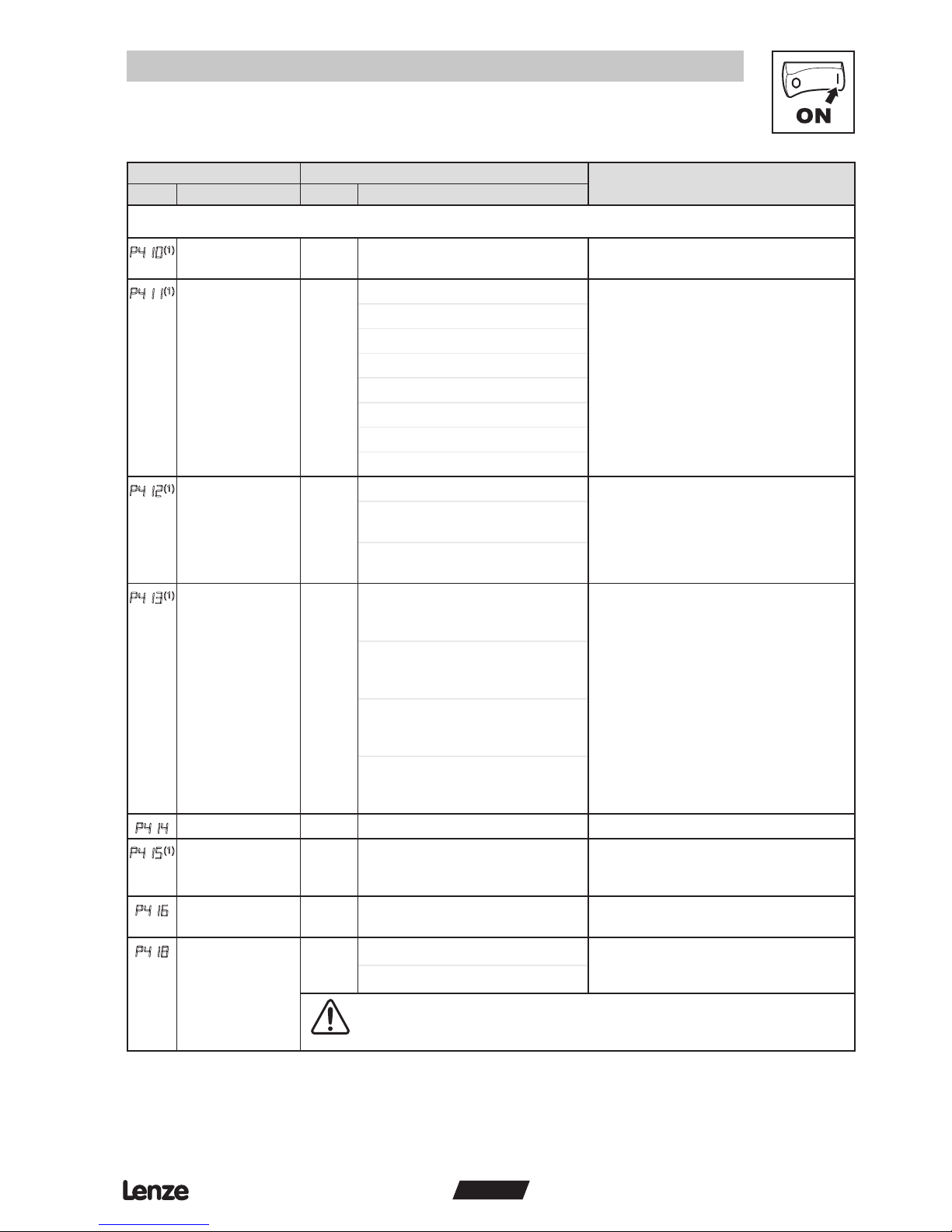
CANopen / System bus parameters
P410
(1)
CAN address
(Node ID)
1 1 127 If P413 = 0, 1: maximum setting = 63
P411
(1)
CAN baud rate 5 0 10 kbps (max distance = 5000m)
1 20 kbps (max distance = 2500m)
2 50 kbps (max distance = 1000m)
3 125 kbps (max distance = 500m)
4 250 kbps (max distance = 250m)
5 500 kbps (max distance = 100m)
6 800 kbps (max distance = 50m)
7 1000 kbps (max distance = 25m)
P412
(1)
System bus
participant
0 0 Slave • P417 = 1: Controller enters operational
state automatically
• P417 = 2: Controller sends “NMT start
all nodes” after boot-up time (P415) and
enters operational state
1 Slave with autostart enabled
0x1F80 NMT bootup - bit 2
2 System bus master (not NMT
master)
P413
(1)
Parameter channel
2 (SDO#2)
2 0 Enable: Node ID range (1...63)
with default COB ID for RPDO
and TPDO
• P413 = 0, 1: CAN address 1...63;
64...127 used for SDO2
• SDO#1 COB ID = 1536 + Node ID
• SDO#2 COB ID = 1600 + Node ID
(if enabled)
Default settings:
RPDO#1: COB ID = 0x200 + Node ID
RPDO#2: COB ID = 0x300 + Node ID
TPDO#1: COB ID = 0x180 + Node ID
TPDO#2: COB ID = 0x280 + Node ID
1 Enable: Node ID range (1...63)
with programmable COB ID using
P440, P450, P460, P470
2 Disable: Node ID range (1...127)
with default COB ID for RPDO
and TPDO
3 Disable: Node ID range (1...127)
with programmable COB ID using
P440, P450, P460, P470
P414
SYNC COB ID 128 0 2047 Controller does not generate SYNC object
P415
(1)
Boot up time 3000 0 {ms} 65535 Controller sends “NMT start all nodes”
message after this delay (active only when
P412 = 2)
P416
Heartbeat time 2000 0 {ms} 65535 • Producer heartbeat time
• P416 = 0 disables heartbeat transmission
P418
Reset CAN node 0 0 No action On transition from 0 to 1, re-initializes
CAN controller and activates changes
made to parameters marked with
(1)
1 Reset CAN communication
WARNING!
CAN re-initialization may activate new RPDO configurations, which can result in
changes to present controller state, including starting.
(1)
These parameters take effect only after power-up, P418 reset, “NMT reset node”, or “NMT reset communication services”
Page 12
10
ENGLISH
Commissioning
Code Possible Settings
IMPORTANT
No. Name Default Selection
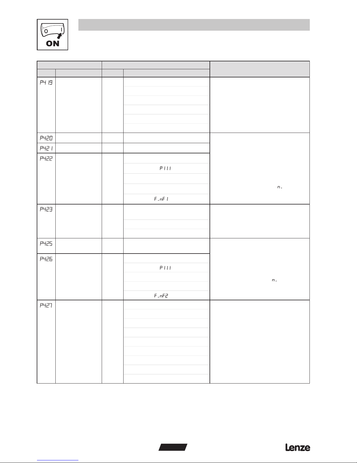
P419
CANopen status 0 Not initialized • Read-only
• Note: RPDOs and TPDOs are only
active in operational state (P419 = 5)
1 Initializing
2 Stopped
3 Pre-operational
4 reserved
5 Operational
P420
Guard time 0 0 {ms} 65535 • P420 x P421 = node life time
• If RTR frame with ID = 0x700 + Node
ID (P410) is not received during the
node life time, the controller will react
according to P422
• If heart beat message is enabled, the
guard function is disabled
• P422 is only active when drive is
in Network Control mode (n.xxx)
and at least one RTR frame with
ID=0x700+NODE ID has been received.
P421
Life time factor 0 0 255
P422
Guard time event
reaction
0 0 Not active
1 STOP (see
P111)
2 Quick stop
3 Inhibit
4 Trip fault
F.nF1
P423
Error behavior 1
0 transition to pre-operational
(only if current state is operational)
Specifies action taken by the drive when it
encounters a communication error
(ex. Node guarding event or Bus Off)
1 No state change
2 transition to stopped
P425
Message
monitoring time
0 0 {ms} 65535 • P425 and P426 can be used to monitor
all valid messages (e.g. SDO, SYNC,
PDO...)
• P425 = 0 or P426 = 0 disables message
monitoring function
• P426 is only active when drive is in
Network Control Mode (n.xxx)
P426
Message
monitoring time
out reaction
0 0 Not active
1 STOP (see P111)
2 Quick stop
3 Inhibit
4 Trip fault
F.nF2
P427
Monitoring timeout status
Bits: • Read-only
• Indicates cause of
F.nt (trip fault,
inhibit, quick stop, or Stop) depending
on the settings of P422, P426, P445,
P455
0 Guard time time-out
1 No valid message received
2 RPD01 time-out
3 RPD02 time-out
4 reserved
5 reserved
6 reserved
7 reserved
Page 13
11
ENGLISH
Commissioning
Code Possible Settings
IMPORTANT
No. Name Default Selection
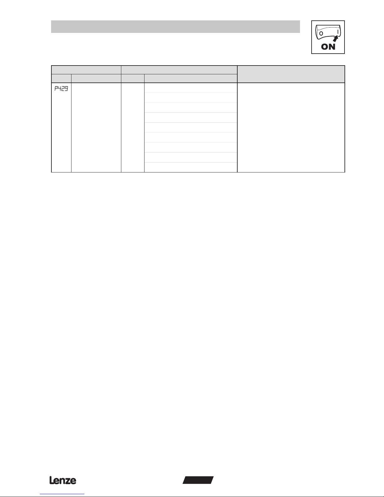
P429
CAN Peripheral
Status
Bits: • Read-only
• CAN warnings and errors
0 Error passive mode
1 Bus off mode
2 CAN Enabled
3 Receiver busy
4 Transmitter busy
5 Transmit error count > 128
6 Overload frame
7 Receive error count > 128
Page 14
12
ENGLISH
Commissioning
Code Possible Settings
IMPORTANT
No. Name Default Selection
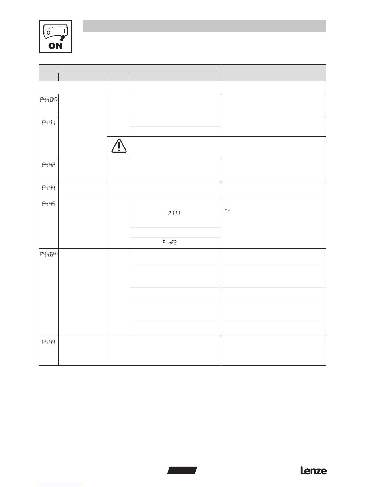
RPDO#1 configuration parameters
P440
(2)
RPDO#1 COB ID 513 0 2047 If P413 = 0, 2: Setting will change to
512 + Node ID during power-up or P418
reset.
P441
RPDO#1
enable/disable
1 0 Disable
1 Enable
WARNING!
CAN re-initialization may activate new RPDO configurations, which can result in
changes to present controller state, including starting.
P442
RPDO#1
transmission type
255 0 255 • P442 = 0...240: transfer on every SYNC
received.
• P442 = 254, 255: immediate transfer
P444
RPDO#1 event
monitoring timer
0 0 {ms} 65535 P444 = 0: monitoring disabled
P445
RPDO#1 time out
reaction
0 0 Not active Only active when in Network Control
(n.xxx)
1 STOP (see
P111)
2 Quick stop
3 Inhibit
4 Trip fault
F.nF3
P446
(2)
RPDO#1 mapping
(see RPDO
mapping details)
2 0 DSP402 (Drives & Motion Control):
PDO Control Word 0x6040
1 DSP402 (Drives & Motion Control):
PDO Control Word 0x6040 +
vl target velocity 0x6042
• vl target velocity units = signed RPM.
• RPM calculation based on P304 and
P305
2 Drive Control Word + Network
Speed
Network Control Frequency Scaling:
10 = 1.0 Hz
3 Drive Control Word + PID
Setpoint
Signed PID Setpoint: -999 … 31,000
4 Drive Control Word + Torque
Setpoint
Torque Setpoint: 0…400%
P449
RPDO#1 counter 0 255 • Read-only
• Number of received RPDO#1 messages
• Above 255, starts over at 0
(2)
These parameters take effect only after power-up, P418 reset, P441 transition from disable to enable, “NMT reset node”, or “NMT reset communication services”
Page 15
13
ENGLISH
Commissioning
Code Possible Settings
IMPORTANT
No. Name Default Selection
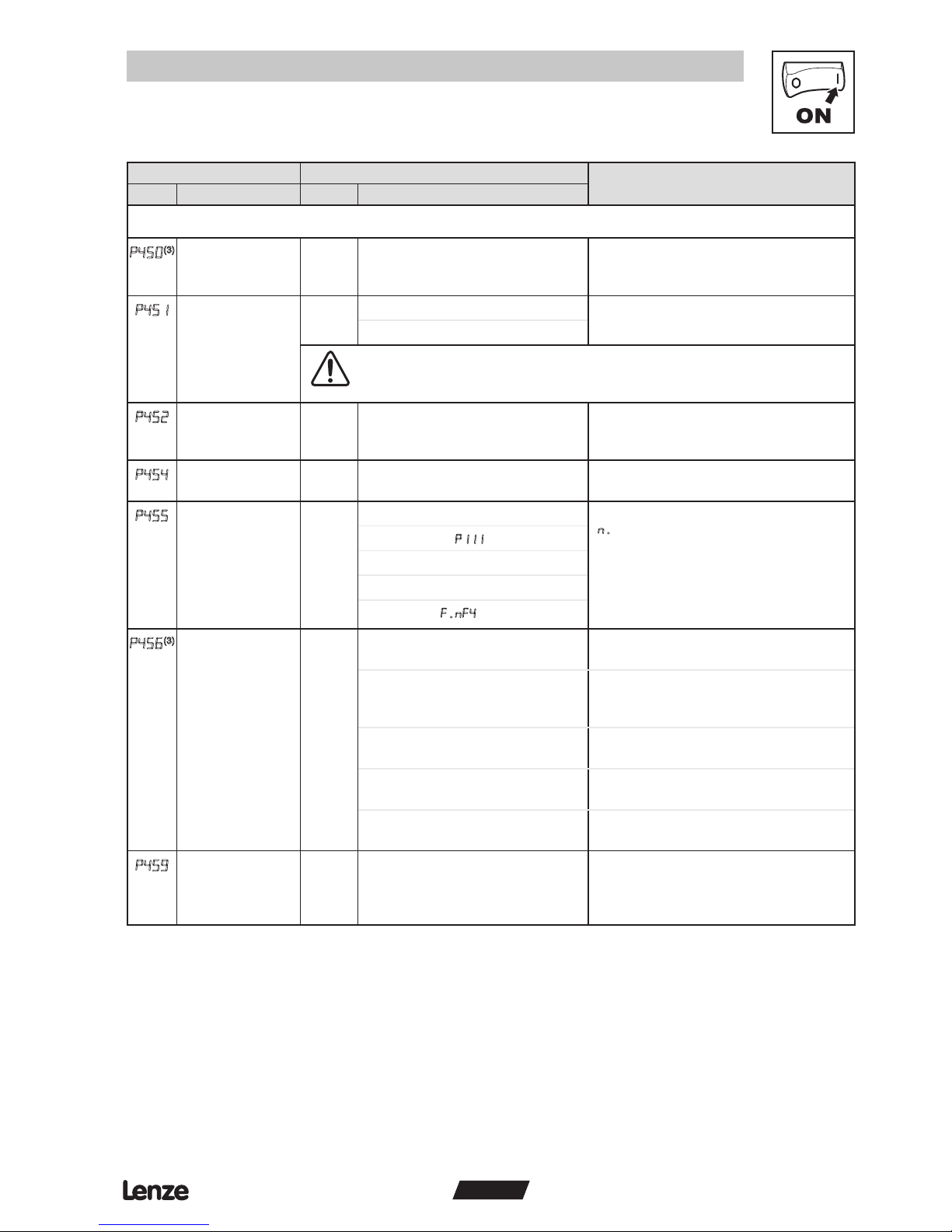
RPDO#2 configuration parameters
P450
(3)
RPDO#2 COB ID 769 0 2047 If P413 = 0, 2: Setting will change to
768 + Node ID during power-up or P418
reset.
P451
RPDO#2
enable/disable
0 0 Disable
1 Enable
WARNING!
CAN re-initialization may activate new RPDO configurations, which can result in
changes to present controller state, including starting.
P452
RPDO#2
transmission type
255 0 255 • P452 = 0...240: transfer on every SYNC
received
• P452 = 254, 255: immediate transfer
P454
RPDO#2 event
monitoring timer
0 0 {ms} 65535 P454 = 0: monitoring disabled
P455
RPDO#2 time out
reaction
0 0 Not active Only active when in Network Control
(n.xxx)
1 STOP (see
P111)
2 Quick stop
3 Inhibit
4 Trip fault
F.nF4
P456
(3)
RPDO#2 mapping
(see RPDO
mapping details)
2 0 DSP402 (Drives & Motion Control):
PDO Control Word 0x6040
1 DSP402 (Drives & Motion Control):
PDO Control Word 0x6040 +
vl target velocity 0x6042
• vl target velocity units = signed RPM.
• RPM calculation based on P304 and
P305
2 Drive Control Word + Network
Speed
Network Control Frequency Scaling:
10 = 1.0 Hz
3 Drive Control Word + PID
Setpoint
Signed PID Setpoint: -999 … 31,000
4 Drive Control Word + Torque
Setpoint
Torque Setpoint: 0…400%
p459
RPDO#2 counter 0 255 • Read-only
• Number of received RPDO#2 messages
• Above 255, starts over at 0
(3)
These parameters take effect only after power-up, P418 reset, P451 transition from disable to enable, “NMT reset node”, or “NMT reset communication services”
Page 16
SMVector
14
ENGLISH
Commissioning
Code Possible Settings
IMPORTANT
No. Name Default Selection
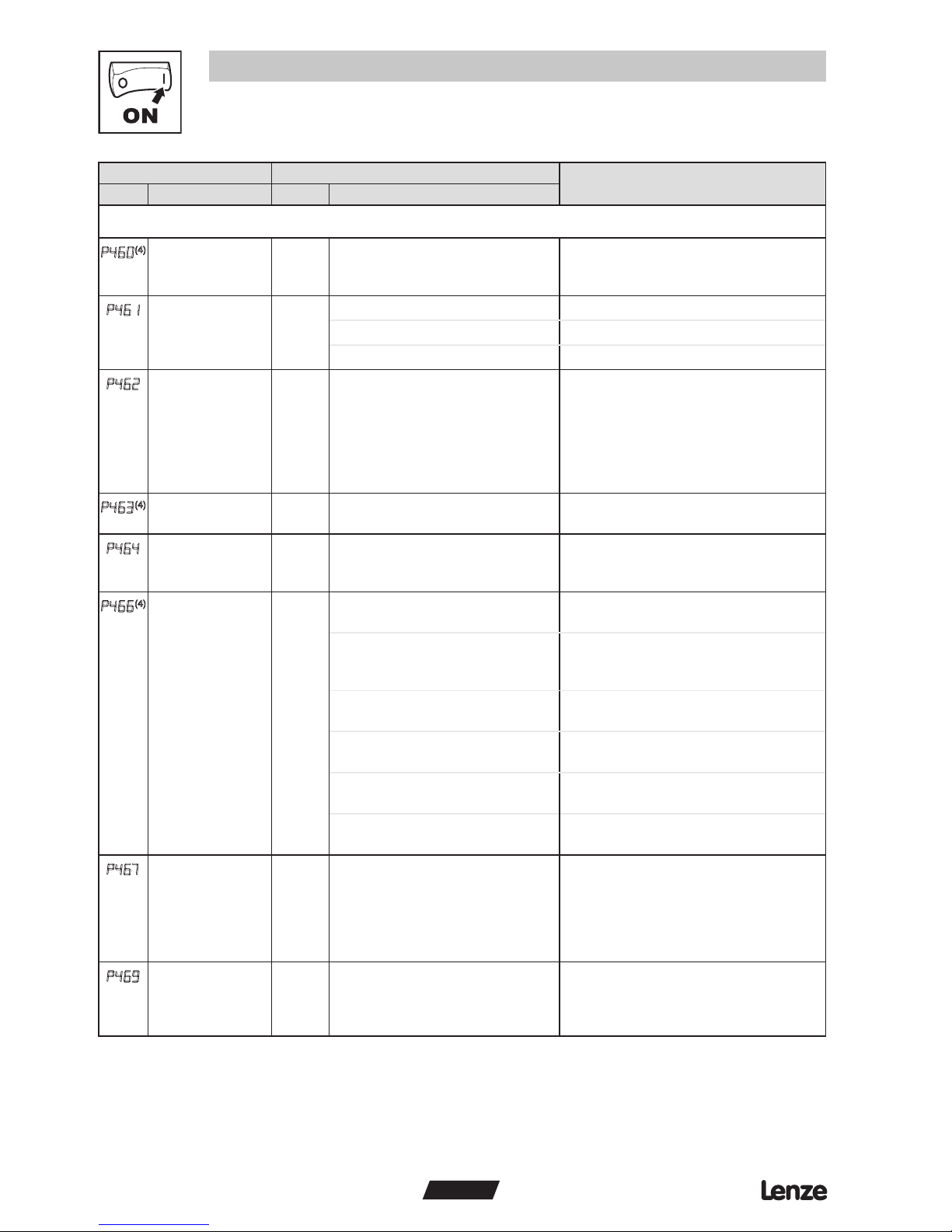
TPDO#1 configuration parameters
P460
(4)
TPDO#1 COB ID 385 0 2047 If P413 = 0, 2: Setting will change to
384 + Node ID during power-up or P418
reset.
P461
TPDO#1
enable/disable
2 0 Disable
1 Enable (no RTR)
2 Enable (with RTR)
Enable individual polling of TPDO#1
P462
TPDO#1
transmission type
255 0 255 • P462 = 0...240: Transmit TPDO#1 after
every nth SYNC received + Event +
RTR (if enabled)
• P462 = 253: Event + RTR (if enabled)
• P462 = 254: COS triggered (WORD0 of
TPDO#1) + Event + RTR (if enabled)
• P462 = 255: Event + RTR (if enabled)
P463
(4)
TPDO#1 inhibit
time
0.0 0.0 {0.1 ms} 65535 Sets minimum time between TPDO#1
transmissions.
P464
TPDO#1 event
timer
0 0 {ms} 65535 • Sets the fixed interval for TPDO#1
transmission
• P464 = 0: disables event timer
P466
(4)
TPDO#1 mapping
(see TPDO
mapping details)
2 0 DSP402 (Drives & Motion Control):
Status Word 0x6041
1 DSP402 (Drives & Motion Control):
Status Word 0x6041 +
vl target velocity 0x6044
• vl control effort units = signed RPM.
• RPM calculation based on P304 and
P305
2 Drive Status Word + Actual
Frequency + I/O
Actual Frequency Scaling: 10 = 1.0 Hz
3 Drive Status Word + Actual
Frequency + PID Setpoint
Signed PID Setpoint: -999 … 31,000
4 Drive Status Word + Actual
Frequency + Torque Setpoint
Torque Setpoint: 0…400%
5 Status Word matches the drives
Control Word
Setting used to control another
Drive. See Appendix A1.1.
P467
TPDO#1 WORD0
bit mask
65535 0 65535 • COS (change of state) bit mask applied
to WORD0 of TPDO selected by P466.
• P467 = 65535: activates all bits of
WORD0 for COS triggering
• P467 = 0: disables COS triggering
• P462 = 254
P469
TPDO#1 counter 0 255 • Read-only
• Number of transmitted TPDO#1
messages
• Above 255, starts over at 0
(4)
These parameters take effect only after power-up, P418 reset, P461 transition from disable to enable, “NMT reset node”, or “NMT reset communication services”
Page 17
SMVector
15
ENGLISH
Commissioning
Code Possible Settings
IMPORTANT
No. Name Default Selection
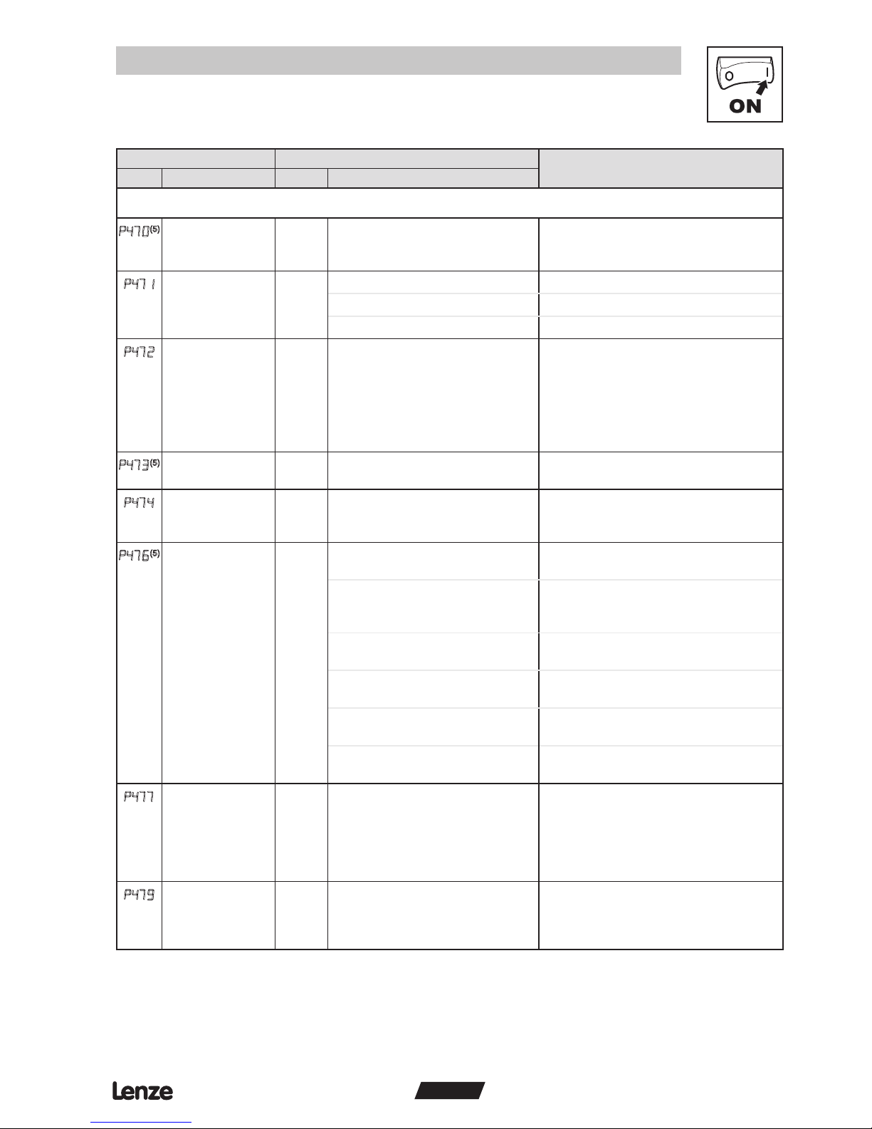
TPDO#2 configuration parameters
P470
(5)
TPDO#2 COB ID 641 0 2047 If P413 = 0, 2: Setting will change to
640 + Node ID during power-up or P418
reset.
P471
TPDO#2
enable/disable
0 0 Disable
1 Enable (no RTR)
2 Enable (with RTR)
Enable individual polling of TPDO#2
P472
TPDO#2
transmission type
255 0 255 • P472 = 0...240: Transmit TPDO#2 after
every nth SYNC received + Event +
RTR (if enabled)
• P472 = 253: Event + RTR (if enabled)
• P472 = 254: COS triggered (WORD0 of
TPDO#2) + Event + RTR (if enabled)
• P472 = 255: Event + RTR (if enabled)
P473
(5)
TPDO#2 inhibit
time
0.0 0.0 {0.1 ms} 65535 Sets minimum time between TPDO#2
transmissions.
P474
TPDO#2 event
timer
0 0 {ms} 65535 • Sets the fixed interval for TPDO#2
transmission
• P474 = 0: disables event timer
P476
(5)
TPDO#2 mapping
(see TPDO
mapping details)
2 0 DSP402 (Drives & Motion Control):
Status Word 0x6041
1 DSP402 (Drives & Motion Control):
Status Word 0x6041 +
vl target velocity 0x6044
• vl control effort units = signed RPM.
• RPM calculation based on P304 and
P305
2 Drive Status Word + Actual
Frequency + I/O
Actual Frequency Scaling: 10 = 1.0 Hz
3 Drive Status Word + Actual
Frequency + PID Setpoint
Signed PID Setpoint: -999 … 31,000
4 Drive Status Word + Actual
Frequency + Torque Setpoint
Torque Setpoint: 0…400%
5 Status Word matches the drives
Control Word
Setting used to control another
Drive. See Appendix A1 - Example 1.
P477
TPDO#2 WORD0
bit mask
65535 0 65535 • COS (change of state) bit mask applied
to WORD0 of TPDO selected by P476.
• P477 = 65535: activates all bits of
WORD0 for COS triggering
• P477 = 0: disables COS triggering
• P472 = 254
P479
TPDO#2 counter 0 255 • Read-only
• Number of transmitted TPDO#2
messages
• Above 255, starts over at 0
(5)
These parameters take effect only after power-up, P418 reset, P471 transition from disable to enable, “NMT reset node”, or “NMT reset communication services”
Page 18
16
ENGLISH
Commissioning
Code Possible Settings
IMPORTANT
No. Name Default Selection
CANopen Module Specific parameters
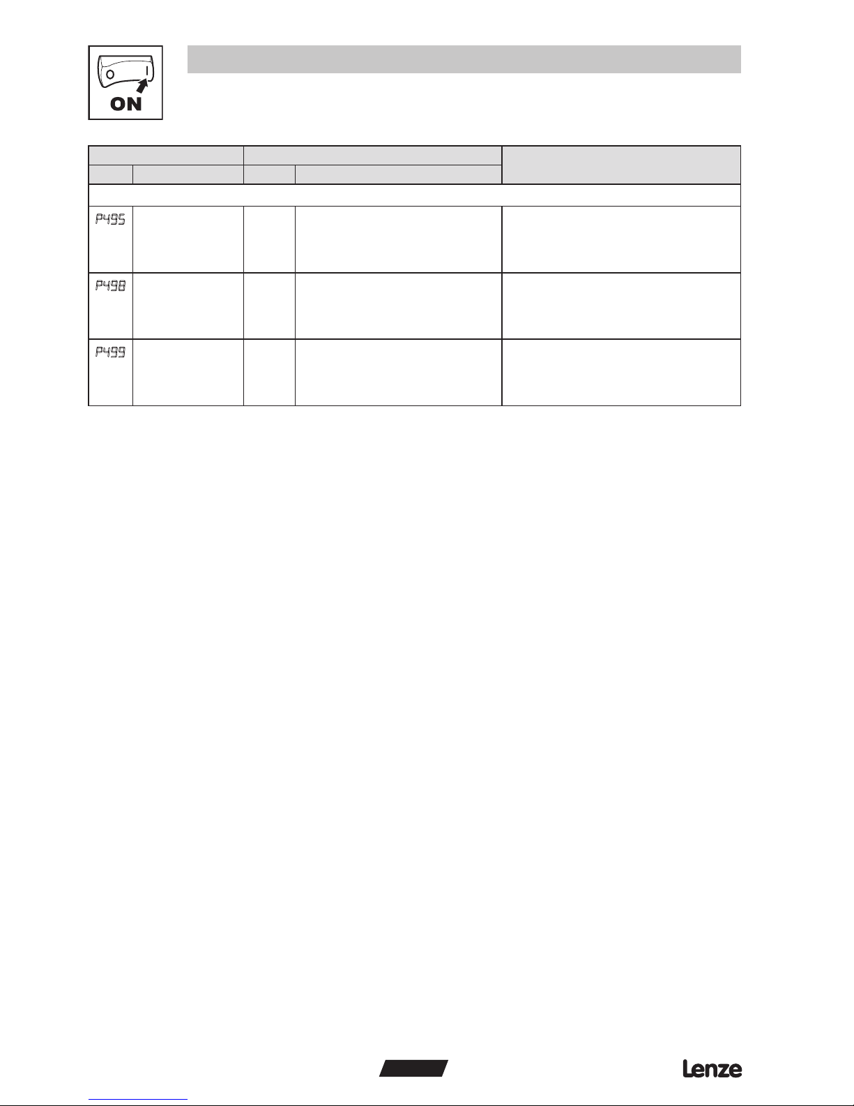
P495
Communication
Module software
version
• Read only
• Alternating Display: xxx-; -yy
P498
Missed Messages
Drive to Module
• Read only
P499
Missed Messages
Module to Drive
• Read only
Page 19
17
ENGLISH
Commissioning
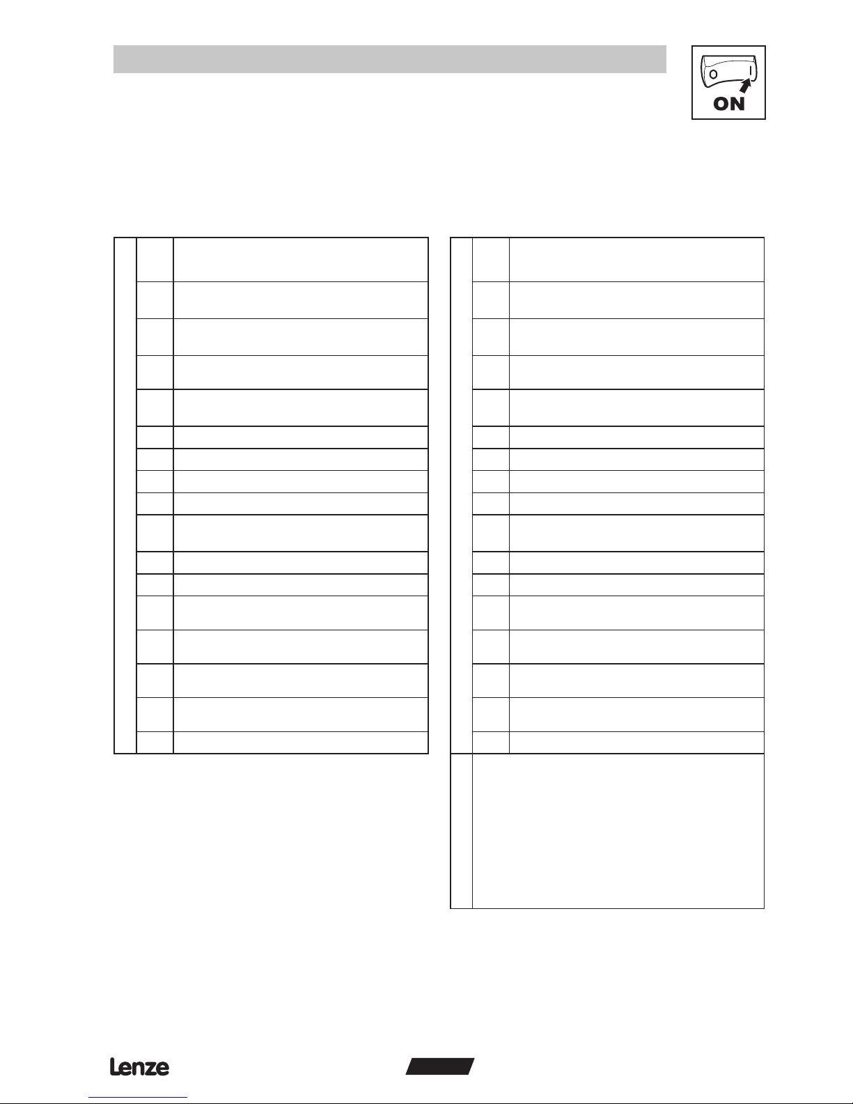
5.2 CANopen mapping details
The tables in the following sections may use descriptions from the CANopen DSP 402 standard. This
terminology should not be interpreted as referring to drive hardware.
5.2.1 RPDO mapping details (P446/P456)
WORD0 - DSP402 control word 0x6040
Bit P446 / P456 setting = 0
WORD0 - DSP402 control word 0x6040
Bit P446 / P456 setting = 1
0
Output Switch
(6)
0 = switch OFF (i) 1 = switch ON (e)
0
Output Switch
(6)
0 = switch OFF (i) 1 = switch ON (e)
1
Voltage Enable
(6)
0 = Disable Voltage (i) 1 = Enable Voltage (e)
1
Voltage Enable
(6)
0 = Disable Voltage (i) 1 = Enable Voltage (e)
2
Quick stop
0 = Quick stop active 1 = Quick stop not active
2
Quick stop
0 = Quick stop active 1 = Quick stop not active
3
Controller inhibit
(6)
0 = Controller inhibit (i) 1 = No controller inhibit (e)
3
Controller inhibit
(6)
0 = Controller inhibit (i) 1 = No controller inhibit (e)
4 Reserved 4 Reserved
5 Reserved 5 Reserved
6 Reserved 6 Reserved
7 Fault Reset: on transition from 0 to 1 7 Fault Reset: on transition from 0 to 1
8
Motion Inhibit
(6)
0 = execute motion (e) 1 = halt (i)
8
Motion Inhibit
(6)
0 = execute motion (e) 1 = halt (i)
9 Reserved 9 Reserved
10 Reserved 10 Reserved
11
Direction of rotation
0 = CW (forward) 1 = CCW (reverse)
11
Direction of rotation
0 = CW (forward) 1 = CCW (reverse)
12
Control
0 = Local Control 1 = Network Control
12
Control
0 = Local Control 1 = Network Control
13
Speed Reference
0 = Local Reference 1 = Network Reference
13
Speed Reference
0 = Local Reference 1 = Network Reference
14
DC brake
0 = DC brake not active 1 = DC brake active
14
DC brake
0 = DC brake not active 1 = DC brake active
15 Reserved 15 Reserved
WORD1
Signed vl target velocity 0x6042 (RPM)
• RPM calculation based on P304 and P305
• Example 1: P304 = 60Hz; P305 = 1750 RPM
request setpoint forward (CW) at 25.0 HZ =
25.0 x 1750/60 = 729 = 0x02D9
• Example 2: P304 = 50Hz; P305 = 1390 RPM
request setpoint reverse (CCW) at 44.5 HZ =
-(44.5 x 1390/50) = -1237 = 0xFB2B
Note: sign of the target velocity takes priority over
bit 11 in word 0!
(6)
Action of indicated bit is implemented as inhibit. These bits inhibit the drive when in the state indicated with (i) and enable the drive in the state indicated with (e).
Page 20
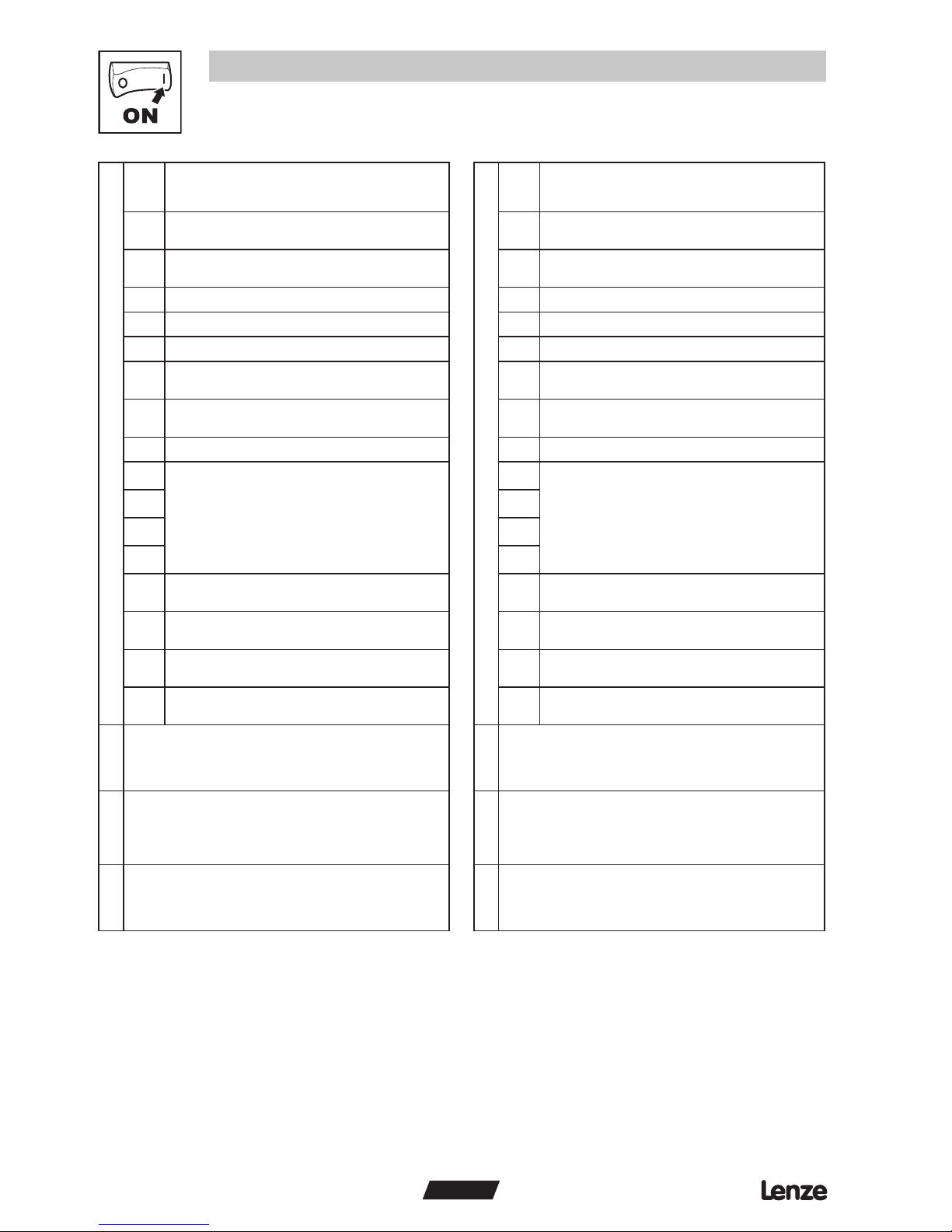
WORD0 - SMV control word
WORD0 - SMV control word
18
ENGLISH
Commissioning
Bit P446 / P456 setting = 2
Bit P446 / P456 setting = 3
0
Run Forward
0 = NOT Run Forward 1 = Run Forward
0
Run Forward
0 = NOT Run Forward 1 = Run Forward
1
Run Reverse
0 = NOT Run Reverse 1 = Run Reverse
1
Run Reverse
0 = NOT Run Reverse 1 = Run Reverse
2 Fault Reset: on transition from 0 to 1 2 Fault Reset: on transition from 0 to 1
3 Reserved 3 Reserved
4 Reserved 4 Reserved
5
Control
0 = Local Control 1 = Network Control
5
Control
0 = Local Control 1 = Network Control
6
Speed Reference
0 = Local Reference 1 = Network Reference
6
Speed Reference
0 = Local Reference 1 = Network Reference
7 Reserved 7 Reserved
8
Network setpoint / reference (when Bit 6 = 1)
0 - Network 6 - Preset #3
1 - Keypad 7 - Preset #4
(7)
2 - 0-10VDC 8 - Preset #5
(7)
3 - 4-20mA 9 - Preset #6
(7)
4 - Preset #1 10 - Preset #7
(7)
5 - Preset #2 11 - MOP
8
Network setpoint / reference (when Bit 6 = 1)
0 - Network 6 - Preset #3
1 - Keypad 7 - Preset #4
(7)
2 - 0-10VDC 8 - Preset #5
(7)
3 - 4-20mA 9 - Preset #6
(7)
4 - Preset #1 10 - Preset #7
(7)
5 - Preset #2 11 - MOP
9 9
10 10
11 11
12
Controller inhibit
0 = No controller inhibit 1 = Controller inhibit
12
Controller inhibit
0 = No controller inhibit 1 = Controller inhibit
13
Quick stop
0 = Quick stop not active 1 = Quick stop active
13
Quick stop
0 = Quick stop not active 1 = Quick stop active
14
Force Mode (Network / PID modes only)
0 = No Action 1 = Force Manual / Open Loop Mode
14
Force Mode (Network / PID modes only)
0 = No Action 1 = Force Manual / Open Loop Mode
15
DC brake
0 = DC brake not active 1 = DC brake active
15
DC brake
0 = DC brake not active 1 = DC brake active
WORD1
Unsigned speed 0.1 Hz resolution
• Received value = 0x01F0 = 49.6 Hz
WORD1
Network PID setpoint
Signed value -999…3100
WORD2
Digital Output and Relay; Active when:
• Bit 9 = Open Collector (and P142 = 25)
• Bit 10 = Relay (and P140 = 25)
Others reserved for future use
WORD2
Digital Output and Relay; Active when:
• Bit 9 = Open Collector (and P142 = 25)
• Bit 10 = Relay (and P140 = 25)
Others reserved for future use
WORD3
Analog Output [0.01 VDC]; Active when P150 = 9
• Received value = 0x024B = 5.87 VDC
WORD3
Analog Output [0.01 VDC]; Active when P150 = 9
• Received value = 0x024B = 5.87 VDC
(7)
Preset #4, #5, #6 and #7 are ignored when the drive is operating in either PID Mode or Torque Mode.
Page 21
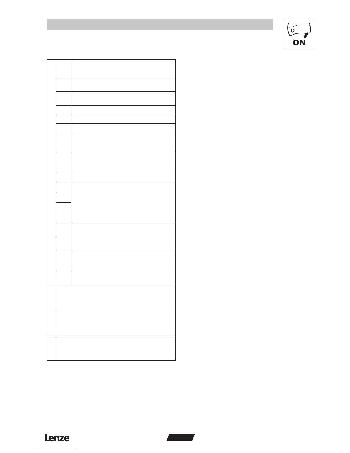
WORD0 - SMV control word
19
ENGLISH
Commissioning
Bit P446 / P456 setting = 4
0
Run Forward
0 = NOT Run Forward 1 = Run Forward
1
Run Reverse
0 = NOT Run Reverse 1 = Run Reverse
2 Fault Reset: on transition from 0 to 1
3 Reserved
4 Reserved
5
Control
0 = Local Control 1 = Network Control
6
Speed Reference
0 = Local Reference 1 = Network Reference
7 Reserved
8
Network setpoint / reference (when Bit 6 = 1)
0 - Network 6 - Preset #3
1 - Keypad 7 - Preset #4
(7)
2 - 0-10VDC 8 - Preset #5
(7)
3 - 4-20mA 9 - Preset #6
(7)
4 - Preset #1 10 - Preset #7
(7)
5 - Preset #2 11 - MOP
9
10
11
12
Controller inhibit
0 = No controller inhibit 1 = Controller inhibit
13
Quick stop
0 = Quick stop not active 1 = Quick stop active
14
Force Mode (Network / PID modes only)
0 = No Action 1 = Force Manual / Open Loop Mode
15
DC brake
0 = DC brake not active 1 = DC brake active
WORD1
Unsigned Torque Setpoint
0 - 400% limited by P330 (Torque Limit)
WORD2
Digital Output and Relay; Active when:
• Bit 9 = Open Collector (and P142 = 25)
• Bit 10 = Relay (and P140 = 25)
Others reserved for future use
WORD3
Analog Output [0.01 VDCC]; Active when P150 = 9
• Received value = 0x024B = 5.87 VDC
(7)
Preset #4, #5, #6 and #7 are ignored when the drive is operating in either PID Mode or Torque Mode.
Page 22
20
ENGLISH
Commissioning
5.2.2 TPDO mapping details (P466/P476)
WORD0 - DSP402 control word 0x6041
Bit P466 / P476 setting = 0
WORD0 - DSP402 control word 0x6041
Bit P466 / P476 setting = 1
0
Ready
0 = Not ready to switch on 1 = Ready to switch on
0
Ready
0 = Not ready to switch on 1 = Ready to switch on
1
Output Switch
0 = switch OFF 1 = switch ON
1
Output Switch
0 = switch OFF 1 = switch ON
2
Operation
0 = operation disabled 1 = operation enabled
2
Operation
0 = operation disabled 1 = operation enabled
3
Fault
0 = No fault 1 = Fault
3
Fault
0 = No fault 1 = Fault
4 Voltage Enable [= 1 (enabled) on drive] 4 Voltage Enable [= 1 (enabled) on drive]
5
Quick stop
0 = Quick stop active 1 = Quick stop not active
5
Quick stop
0 = Quick stop active 1 = Quick stop not active
6 Switch ON enabled [= 0 (disabled) on drive] 6 Switch ON enabled [= 0 (disabled) on drive]
7
Warning
0 = No Warning 1 = Warning
7
Warning
0 = No Warning 1 = Warning
8 Manufacturer specific 8 Manufacturer specific
9
Network
0 = Not Remote (Manual) 1 = Remote (Network)
9
Network
0 = Not Remote (Manual) 1 = Remote (Network)
10
Operation at Setpoint
0 = Setpoint not reached 1 = Setpoint reached
10
Operation at Setpoint
0 = Setpoint not reached 1 = Setpoint reached
11
Internal Limit
0 = Limit NOT active 1 = Internal limit active
11
Internal Limit
0 = Limit NOT active 1 = Internal limit active
12 Reserved 12 Reserved
13 Reserved 13 Reserved
14 Reserved 14 Reserved
15 Reserved 15 Reserved
WORD1
Signed actual output frequency
• RPM calculation based on P304 and P305
• Example 1: P304 = 60Hz; P305 = 1750 RPM
request setpoint forward (CW) at 25.0 HZ =
25.0 x 1750/60 = 729 = 0x02D9
• Example 2: P304 = 50Hz; P305 = 1390 RPM
request setpoint reverse (CCW) at 44.5 HZ =
-(44.5 x 1390/50) = -1237 = 0xFB2B
Page 23
WORD0 - SMV control word
WORD0 - SMV control word
21
ENGLISH
Commissioning
Bit P466 / P476 setting = 2
Bit P466 / P476 setting = 3
0
Drive Fault
0 = No Fault 1 = Faulted
0
Drive Fault
0 = No Fault 1 = Faulted
1 Reserved 1 Reserved
2
Run Forward
0 = NOT Run Forward 1 = Run Forward
2
Run Forward
0 = NOT Run Forward 1 = Run Forward
3
Run Reverse
0 = NOT Run Reverse 1 = Run Reverse
3
Run Reverse
0 = NOT Run Reverse 1 = Run Reverse
4
Drive Status
0 = NOT Ready 1 = Ready
4
Drive Status
0 = NOT Ready 1 = Ready
5
Control
0 = Local Control 1 = Network Control
5
Control
0 = Local Control 1 = Network Control
6
Speed Reference
0 = Local Reference 1 = Network Reference
6
Speed Reference
0 = Local Reference 1 = Network Reference
7
Operation at Setpoint
0 = Setpoint not reached 1 = Setpoint reached
7
Operation at Setpoint
0 = Setpoint not reached 1 = Setpoint reached
8
Actual setpoint / reference source
0 - Keypad 6 - Preset #4
1 - 0-10VDC 7 - Preset #5
2 - 4-20mA 8 - Preset #6
3 - Preset #1 9 - Preset #7
4 - Preset #2 10 - MOP
5 - Preset #3 11 - Network
8
Actual setpoint / reference source
0 - Keypad 6 - Preset #4
1 - 0-10VDC 7 - Preset #5
2 - 4-20mA 8 - Preset #6
3 - Preset #1 9 - Preset #7
4 - Preset #2 10 - MOP
5 - Preset #3 11 - Network
9 9
10 10
11 11
12
PID Mode Status
0 = PID NOT Active 1 = PID Active
12
PID Mode Status
0 = PID NOT Active 1 = PID Active
13
Torque Mode Status
0 = NOT in Torque Mode 1 = Torque Mode Active
13
Torque Mode Status
0 = NOT in Torque Mode 1 = Torque Mode Active
14
Current Limit Status
0 = NOT in Current Limit 1 = in Current Limit
14
Current Limit Status
0 = NOT in Current Limit 1 = in Current Limit
15
DC brake
0 = DC brake not active 1 = DC brake active
15
DC brake
0 = DC brake not active 1 = DC brake active
WORD1
Unsigned speed 0.1 Hz resolution
WORD1
Unsigned actual frequency 0.1 Hz resolution
WORD2
Digital input/Output States
Bit 2 - Output Fault Bit 3 - Fast Current Limit State
Bit 4 - TB1 ON Bit 6 - TB13A
Bit 7 - TB13B Bit 8 - TB13C
Bit 9 - TB14 Out State Bit 10 - Relay State
Bit 11 - Charge Relay Bit 12 - Assertion Level
WORD2
Actual PID setpoint
Signed value -999…3100
WORD3
Analog Input [0.01 VDC]; Active when P150 = 9
• Received value = 0x024B = 5.87 VDC
WORD3
Actual PID feedback
Signed value -999…3100
Page 24
WORD0 - SMV control word
WORD0 - SMV control word
22
ENGLISH
Commissioning
Bit P466 / P476 setting = 4 Bit
P466 / P476 setting = 5
(Special for Daisy Chaining)
0
Drive Fault
0 = No Fault 1 = Faulted
0
Run Forward
0 = NOT Run Forward 1 = Run Forward
1 Reserved 1
Run Reverse
0 = NOT Run Reverse 1 = Run Reverse
2
Run Forward
0 = NOT Run Forward 1 = Run Forward
2 Fault Reset: on transition from 0 to 1
3
Run Reverse
0 = NOT Run Reverse 1 = Run Reverse
3 Reserved
4
Drive Status
0 = NOT Ready 1 = Ready
4 Reserved
5
Control
0 = Local Control 1 = Network Control
5
Control
1 = Network Control
(set to 1 to match Network Control on RPDO)
6
Speed Reference
0 = Local Reference 1 = Network Reference
6
Speed Reference
1 = Network Reference
(set to 1 to match speed reference on RPDO)
7
Operation at Setpoint
0 = Setpoint not reached 1 = Setpoint reached
7 Reserved
8
Actual setpoint / reference source
0 - Keypad 6 - Preset #4
1 - 0-10VDC 7 - Preset #5
2 - 4-20mA 8 - Preset #6
3 - Preset #1 9 - Preset #7
4 - Preset #2 10 - MOP
5 - Preset #3 11 - Network
8
Actual setpoint / reference source
0 - Network 6 - Preset #3
1 - Reserved 7 - Preset #4
2 - Reserved 8 - Preset #5
3 - Reserved 9 - Preset #6
4 - Preset #1 10 - Preset #7
5 - Preset #2 11 - Reserved
9 9
10 10
11 11
12
PID Mode Status
0 = PID NOT Active 1 = PID Active
12
Controller inhibit
0 = No controller inhibit 1 = Controller inhibit
13
Torque Mode Status
0 = NOT in Torque Mode 1 = Torque Mode Active
13
Quick stop
0 = Quick stop not active 1 = Quick stop active
14
Current Limit Status
0 = NOT in Current Limit 1 = in Current Limit
14
Force Mode (Network / PID modes only)
0 = No Action 1 = Force Manual / Open Loop Mode
(must be set to 0)
15
DC brake
0 = DC brake not active 1 = DC brake active
15
DC brake
0 = DC brake not active 1 = DC brake active
WORD1
Unsigned actual frequency 0.1 Hz resolution
WORD1
Unsigned Command speed 0.1 Hz resolution
• Received value = 0x01F0 = 49.6 Hz
WORD2
Actual Torque [%]
WORD2
Digital Output and Relay; Active when:
• Bit 9 = Open Collector (and P142 = 25)
• Bit 10 = Relay (and P140 = 25)
Others reserved for future use
WORD3
Analog Input 0-10 VDC TB [0.01 VDC]
• Received value = 0x024B = 5.87 VDC
WORD3
Analog Output [0.01 VDCC]; Active when P150 = 9
• Received value = 0x024B = 5.87 VDC
Page 25
23
ENGLISH
Troubleshooting and fault elimination
6 Troubleshooting and fault elimination
6.1 Faults
Status Cause Remedy
f.ntf
Module to Drive communication
time out
Connection between drive and
module is not made.
Check cable and connection
between module and drive
F.nF1
Guard Time Fault See parameters P420, P421, P423
F.nF2
Message Monitoring time-out See parameters P425, P426
F.nF3
RPDO#1 Monitoring time-out See parameters P444, P445
F.nF4
RPDO#2 Monitoring time-out See parameters P454, P455
6.2 Troubleshooting
Symptom Possible Cause Remedy
No communication from the
drive
Module is not initialized properly
• Verify the module connection
• Check P400 and P402
Incorrect CANopen settings
• Use P403 to reset CANopen parameters.
• Verify P410 and P411
Improper wiring
• Check wiring between the CANopen Network
and communication module.
• Ensure that terminal block is properly seated.
• Check connection between module and drive.
CANopen write commands are
ignored or return exceptions.
“Network Enabled terminal is either
open or not configured.
Configure one of the input terminals (P121,
P122, or P123) to “Network Enabled” function
(selection 9) and close the corresponding
contact.
Drive stops without obvious
reason
One of the CANopen monitoring
messages timed out and it’s timeout reaction is set to STOP.
Identify the time-out message (P427) and
modify appropriate time-out time or reaction to
the time-out settings.
Page 26
24
ENGLISH
Appendix
A1 Appendix A - Configuration Example
A1.1 Master / Follower drive system
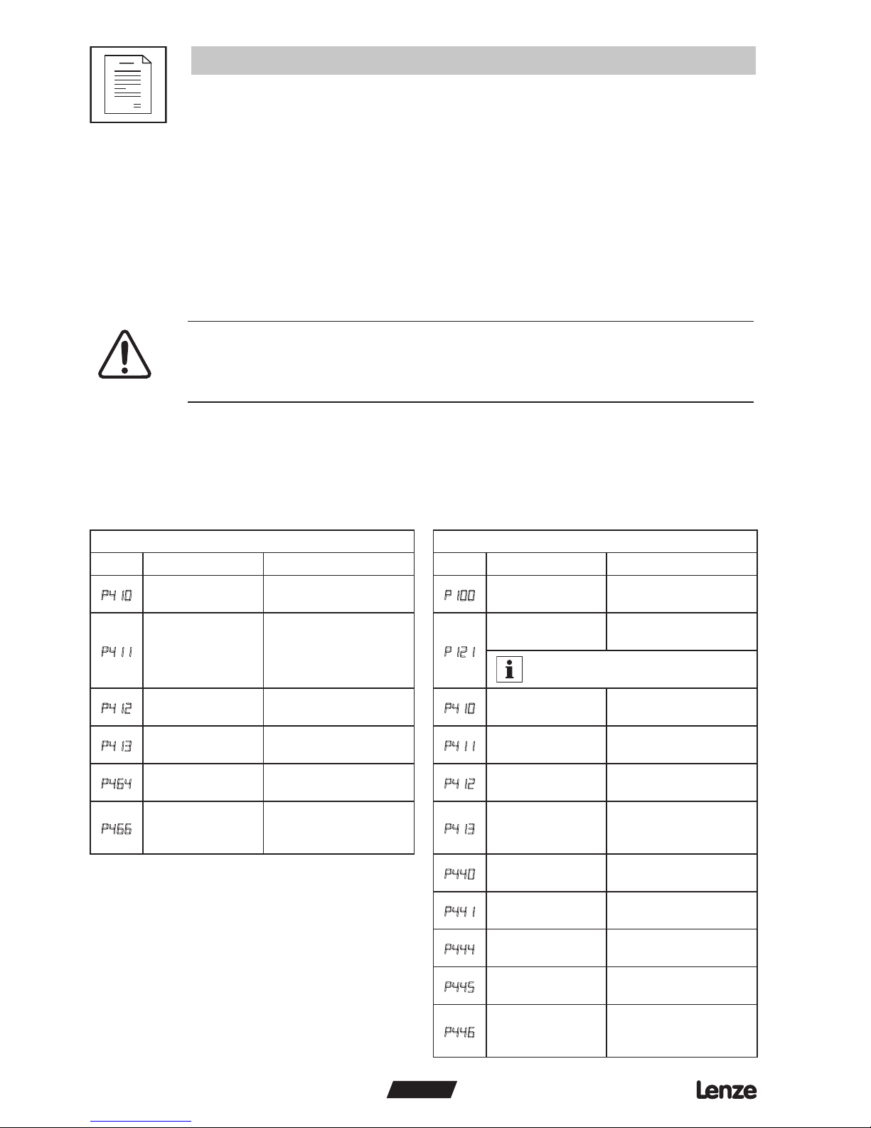
The following example shows how to set up for a typical “Master - Follower” drive system using
CANopen as the link between the two drives. The “Master” drive can be controlled by CANopen or
by traditional control elements (relays, switches, potentiometers, etc.), the “Follower” will receive it’s
commands (run, speed, etc.) from the “Master” when a contact closure (or jumper) is made between
terminals 4 and 13-A to enable Network Control on the follower drive.
WARNING!
Network control permits automatic starting and stopping of the inverter drive. The
system design must incorporate adequate protection to prevent personnel from
accessing moving equipment while power is applied to the drive system.
This example is shown for illustrative purposes only. In an actual implementation, additional safety
precautions must be made. Included in these should be the prevention of access to the “Follower”
drive keypad for operational purposes since the “Master” drive may restart the “Follower” drive even
after a local keypad STOP command. As always, system safety is the responsibility of the machine
designer.
Parameters
Master Drive configuration Follower Drive configuration
No. Name Setting No. Name Setting
P410
CAN address
(Node ID)
1
P100
Setpoint source 3 Network Only
P411
CAN baud rate 5 500 kbps
P121
TB-13A input
function
9 Network Enable
Any of the TB13 inputs can be used,
this example uses TB-13A
P412
System bus
participant
1 Slave with autostart
enabled
P410
CAN address
(Node ID)
2
P413
Parameter channel
2 (SDO#2)
2 Disable with default
COB ID
P411
CAN baud rate 5 500 kbps
P464
TPDO#1 event
timer
10 ms
P412
System bus
participant
1 Slave with autostart
enabled
P466
TPDO#1 mapping
5 Status Word matches
the SMV Control
word.
P413
Parameter channel
2 (SDO#2)
3 Disable with
programmable
COB ID
P440
RPDO#1 COB ID
385
(P460 from controller #1)
P441
RPDO#1
enable/disable
1 Enable
P444
RPDO#1 event
monitoring timer
50 ms
P445
RPDO#1 time out
reaction
1 STOP
P446
RPDO#1 mapping
2 SMV Control Word +
Network Speed.
Page 27
25
ENGLISH
Appendix
After setting the parameters, perform Node reset using parameter P418 or cycle the power.
NOTE:
ANY time the PDO modes or addresses are changed, they must be either disabled/enabled (using
P441 or P451) or the drive must be reset by cycling power.
After these controllers are configured as above, the “Follower” drive will follow the operation of the
“Master” drive, including functions of Inhibit state, Quick Stop, DC brake, preset setpoint selections,
direction, and speed. For additional safety, the “Follower” drive will transition to inhibit state if a valid
PDO is not received from the “Master” within 50ms.
NOTE:
• If the Follower drive does not see a valid PDO within the time-out period, it will transition to the
inhibit state. This action is always immediate STOP by coast, even if the follower specifies other
action in P111. For example, a fault on the Master should cause an inhibit state on the follower
(displayed as STOP) by switching off of all power devices.
• On power up, the drives will not start running unless the master is configured to do so
(P110 = 1, 3, 4,5, or 6). Follower drive will respond with a normal start even if the Master is
configured for flying start.
• While running, the master will continuously send a “run” command to the follower.
Page 28

AC Technology Corporation • 630 Douglas Street • Uxbridge, MA 01569 • USA
+1 (508) 278-9100 www.actech.com
Document
CMVCAN01A
 Loading...