

Lenze MP 5000 DVI, MP 1000 DVI, MP 9000 DVI, MP 1050 DVI, MP 1050s DVI Operating Instructions Manual
...Page 1
BA_MP9000DVI
.NpW
Ä.NpWä
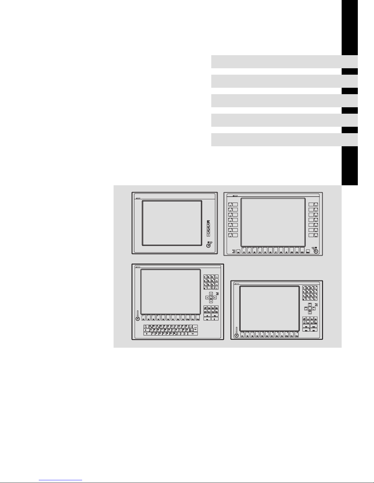
Operating Instructions
Industrial PC
MP 800 DVI ... MP 9000 DVI
Monitor Panel (Embedded Line)
L−force Controls
-
F3
Fail
Power
F1
+
F2
Status
Q+R
F1 F2 F5
-
S T
F3 F4
@\Z
F11F10YXF9F8 F12
WVU
F7F6
Shift
Alpha
Bs
Space
Enter
EscDelIns
MenuAltCtrl
Home
1
I
0
M
4
E
7
A
Pg Dn
*
3
J K L
/
,
N O P
Pg Up
End
Status
Power
Fail
2
.
+6
F G H
-
9
B C D
5
8
"
(
§
&
)
=
/
$
!
>
/
*
-
+
,
|
54 6
87 9
1 2 3
<
0
-
+
Alt Strg
*
+
T
F4
€
D
EWQ
XY
SA
@
F3F1 F2
R
VC
FF5G H J
-
_
Ä
F9F8F6 F7 F10
OI P ÜUZ
Ö
;
,
:
M
μ
.
LK
NB
Space
Enter
\?ß
~
F12
Esc
F11
Pos 1
Einfg
Ende
Entf
Bs
Alt Gr
Fail
Status
Power
Bild
Bild
S13
S14
S11
S10
S12
S6
S7
F3F2
+
-
F4
Status
Power
Fail
F1
Esc
Enter
F11 F12F6F5 F7 F8 F9 F10
S1
S4
S2
S3
S5
S8
S9
Page 2

Please read these instructions before you start working!
Follow the enclosed safety instructions.
Page 3

Contents i
3
BA_MP9000DVI DE 4.0
1 About this documentation 5. . . . . . . . . . . . . . . . . . . . . . . . . . . . . . . . . . . . . . . . . . . . . . . . . .
1.1 Document history 6. . . . . . . . . . . . . . . . . . . . . . . . . . . . . . . . . . . . . . . . . . . . . . . . . . . .
1.2 Conventions used 7. . . . . . . . . . . . . . . . . . . . . . . . . . . . . . . . . . . . . . . . . . . . . . . . . . . .
1.3 Notes used 8. . . . . . . . . . . . . . . . . . . . . . . . . . . . . . . . . . . . . . . . . . . . . . . . . . . . . . . . . .
2 Safety instructions 9. . . . . . . . . . . . . . . . . . . . . . . . . . . . . . . . . . . . . . . . . . . . . . . . . . . . . . . . .
2.1 General safety information 9. . . . . . . . . . . . . . . . . . . . . . . . . . . . . . . . . . . . . . . . . . . .
2.2 Product−specific safety instructions 11. . . . . . . . . . . . . . . . . . . . . . . . . . . . . . . . . . . . .
2.3 Safety instructions for the installation according to UL 12. . . . . . . . . . . . . . . . . . . . .
3 Product description 14. . . . . . . . . . . . . . . . . . . . . . . . . . . . . . . . . . . . . . . . . . . . . . . . . . . . . . . .
3.1 Scope of supply 14. . . . . . . . . . . . . . . . . . . . . . . . . . . . . . . . . . . . . . . . . . . . . . . . . . . . . .
3.2 Application as directed 15. . . . . . . . . . . . . . . . . . . . . . . . . . . . . . . . . . . . . . . . . . . . . . .
3.3 Device features 15. . . . . . . . . . . . . . . . . . . . . . . . . . . . . . . . . . . . . . . . . . . . . . . . . . . . . .
3.4 Identification 18. . . . . . . . . . . . . . . . . . . . . . . . . . . . . . . . . . . . . . . . . . . . . . . . . . . . . . . .
3.5 Controls and displays 19. . . . . . . . . . . . . . . . . . . . . . . . . . . . . . . . . . . . . . . . . . . . . . . . .
4 Technical data 20. . . . . . . . . . . . . . . . . . . . . . . . . . . . . . . . . . . . . . . . . . . . . . . . . . . . . . . . . . . .
4.1 General data and operating conditions 20. . . . . . . . . . . . . . . . . . . . . . . . . . . . . . . . .
4.2 Electrical data 22. . . . . . . . . . . . . . . . . . . . . . . . . . . . . . . . . . . . . . . . . . . . . . . . . . . . . . . .
4.3 Mechanical data 22. . . . . . . . . . . . . . . . . . . . . . . . . . . . . . . . . . . . . . . . . . . . . . . . . . . .
5 Mechanical installation 24. . . . . . . . . . . . . . . . . . . . . . . . . . . . . . . . . . . . . . . . . . . . . . . . . . . . .
5.1 Important notes 24. . . . . . . . . . . . . . . . . . . . . . . . . . . . . . . . . . . . . . . . . . . . . . . . . . . . . .
5.3 Mounting cutout 25. . . . . . . . . . . . . . . . . . . . . . . . . . . . . . . . . . . . . . . . . . . . . . . . . . . . .
5.4 Mounting steps 26. . . . . . . . . . . . . . . . . . . . . . . . . . . . . . . . . . . . . . . . . . . . . . . . . . . . . .
5.4.1 MP 1000(s) DVI / MP 1050(s) DVI 26. . . . . . . . . . . . . . . . . . . . . . . . . . . . . . . .
5.4.2 MP 2xxx DVI / MP 5xxx DVI / MP 9xxx DVI 27. . . . . . . . . . . . . . . . . . . . . . . .
6 Electrical installation 28. . . . . . . . . . . . . . . . . . . . . . . . . . . . . . . . . . . . . . . . . . . . . . . . . . . . . . .
6.1 Important notes 28. . . . . . . . . . . . . . . . . . . . . . . . . . . . . . . . . . . . . . . . . . . . . . . . . . . . . .
6.2 Wiring according to EMC 29. . . . . . . . . . . . . . . . . . . . . . . . . . . . . . . . . . . . . . . . . . . . . .
6.5 Connecting the supply and peripheral devices 30. . . . . . . . . . . . . . . . . . . . . . . . . . . . .
6.5.1 Terminal diagram supply 30. . . . . . . . . . . . . . . . . . . . . . . . . . . . . . . . . . . . . .
6.5.2 24 V connection 30. . . . . . . . . . . . . . . . . . . . . . . . . . . . . . . . . . . . . . . . . . . . . .
6.5.3 DVI interface 31. . . . . . . . . . . . . . . . . . . . . . . . . . . . . . . . . . . . . . . . . . . . . . . . .
6.5.4 USB interface 31. . . . . . . . . . . . . . . . . . . . . . . . . . . . . . . . . . . . . . . . . . . . . . . .
6.5.5 USB interface on the front face (option) 31. . . . . . . . . . . . . . . . . . . . . . . . . .
Page 4

Contentsi
4
BA_MP9000DVI DE 4.0
7 Operation 32. . . . . . . . . . . . . . . . . . . . . . . . . . . . . . . . . . . . . . . . . . . . . . . . . . . . . . . . . . . . . . . .
7.1 Important notes 32. . . . . . . . . . . . . . . . . . . . . . . . . . . . . . . . . . . . . . . . . . . . . . . . . . . . . .
7.3 Controls and displays 33. . . . . . . . . . . . . . . . . . . . . . . . . . . . . . . . . . . . . . . . . . . . . . . . .
7.3.1 Monitor Panel MP 800 DVI / MP 1000 DVI / MP 1000s DVI / MP 2000 DVI /
MP 5000 DVI / MP 9000 DVI 33. . . . . . . . . . . . . . . . . . . . . . . . . . . . . . . . . . . .
7.3.2 Monitor Panel MP 5020 DVI 34. . . . . . . . . . . . . . . . . . . . . . . . . . . . . . . . . . . .
7.3.3 Monitor Panel MP 1050 DVI / MP 1050s DVI / MP 2050 DVI /
MP 5050 DVI 35. . . . . . . . . . . . . . . . . . . . . . . . . . . . . . . . . . . . . . . . . . . . . . . . .
7.3.4 Monitor Panel MP 5070 DVI 36. . . . . . . . . . . . . . . . . . . . . . . . . . . . . . . . . . . .
8 Maintenance 37. . . . . . . . . . . . . . . . . . . . . . . . . . . . . . . . . . . . . . . . . . . . . . . . . . . . . . . . . . . . .
8.1 Regular checks 37. . . . . . . . . . . . . . . . . . . . . . . . . . . . . . . . . . . . . . . . . . . . . . . . . . . . . . .
8.2 Cleaning 38. . . . . . . . . . . . . . . . . . . . . . . . . . . . . . . . . . . . . . . . . . . . . . . . . . . . . . . . . . . .
8.5 Repair 39. . . . . . . . . . . . . . . . . . . . . . . . . . . . . . . . . . . . . . . . . . . . . . . . . . . . . . . . . . . . . .
8.5.1 Removing and mounting the housing 39. . . . . . . . . . . . . . . . . . . . . . . . . . . .
8.5.2 Fuse change 40. . . . . . . . . . . . . . . . . . . . . . . . . . . . . . . . . . . . . . . . . . . . . . . . .
9 Index 41. . . . . . . . . . . . . . . . . . . . . . . . . . . . . . . . . . . . . . . . . . . . . . . . . . . . . . . . . . . . . . . . . . . .
Page 5

About this documentation 1
5
BA_MP9000DVI DE 4.0
0Fig. 0Tab. 0
1 About this documentation
Contents
This documentation provides you with information about the intended use of the monitor
panel.
The present manual is part of the "Controller−based automation" or "PC−based
automation" manual collection which you can find on the DVDs of the same name.
Target group
This documentation is directed at qualified skilled personnel according to IEC 60364.
Qualified skilled personnel are persons who have the required qualifications to carry out
all activities involved in installing, mounting, commissioning, and operating the product.
Tip!
Information and auxiliary devices related to the Lenze products can be found
in the download area at
http://www.Lenze.com
Validity
These instructions are valid for
ƒ MP 800 DVI
ƒ MP 1000 DVI, MP 1000s DVI
ƒ MP 1050 DVI, MP 1050s DVI
ƒ MP 2000 DVI
ƒ MP 2050 DVI
ƒ MP 5000 DVI
ƒ MP 5020 DVI
ƒ MP 5050 DVI
ƒ MP 5070 DVI
ƒ MP 9000 DVI
Page 6
About this documentation
Document history
1
6
BA_MP9000DVI DE 4.0
1.1 Document history
Material number Version Description
.NpW 4.0 02/2014 TD06 New:
l UL notes (French language)
l Notes RJ45 cable laying
13433085 3.0 03/2013 TD29 General revision
13392303 2.0 11/2011 TD29 Supplement of the note concerning the protection
against direct solar radiation, as well as chapter
"Repair"
13385511 1.0 07/2011 TD29 First edition
Page 7

About this documentation
Conventions used
1
7
BA_MP9000DVI DE 4.0
1.2 Conventions used
This documentation uses the following conventions to distinguish between different
types of information:
Type of information Identification Examples/notes
Spelling of numbers
Decimal separator Point In general, the decimal point is used.
For instance: 1234.56
Warnings
UL warnings
Given in English and French
UR warnings
Text
Program name » « PC software
For example: »Engineer«, »Global Drive
Control« (GDC)
Icons
Page reference Reference to another page with additional
information
For instance: 16 = see page 16
Documentation reference Reference to another documentation with
additional information
For example: EDKxxx = see
documentation EDKxxx
Page 8
About this documentation
Notes used
1
8
BA_MP9000DVI DE 4.0
1.3 Notes used
The following pictographs and signal words are used in this documentation to indicate
dangers and important information:
Safety instructions
Structure of safety instructions:
Danger!
(characterises the type and severity of danger)
Note
(describes the danger and gives information about how to prevent dangerous
situations)
Pictograph and signal word Meaning
Danger!
Danger of personal injury through dangerous electrical voltage.
Reference to an imminent danger that may result in death or
serious personal injury if the corresponding measures are not
taken.
Danger!
Danger of personal injury through a general source of danger.
Reference to an imminent danger that may result in death or
serious personal injury if the corresponding measures are not
taken.
Stop!
Danger of property damage.
Reference to a possible danger that may result in property
damage if the corresponding measures are not taken.
Application notes
Pictograph and signal word Meaning
Note!
Important note to ensure troublefree operation
Tip!
Useful tip for simple handling
Reference to another documentation
Special safety instructions and application notes
Pictograph and signal word Meaning
Warnings!
Safety note or application note for the operation according to
UL or CSA requirements.
The measures are required to meet the requirements according
to UL or CSA.
Warnings!
Page 9

Safety instructions
General safety information
2
9
BA_MP9000DVI DE 4.0
2 Safety instructions
2.1 General safety information
Scope
The following general safety instructions apply to all Lenze drive and automation
components.
The product−specific safety and application notes given in this documentation must be
observed!
For your own safety
Danger!
Disregarding the following basic safety measures may lead to severe personal
injury and damage to material assets!
ƒ Lenze drive and automation components ...
... must only be used for the intended purpose.
... must never be operated if damaged.
... must never be subjected to technical modifications.
... must never be operated unless completely assembled.
... must never be operated without the covers/guards.
... can − depending on their degree of protection − have live, movable or rotating parts
during or after operation. Surfaces can be hot.
ƒ For Lenze drive and automation components ...
... only use approved accessories.
... only use original manufacturer spare parts.
ƒ All specifications of the corresponding enclosed documentation must be observed.
This is vital for a safe and trouble−free operation and for achieving the specified product
features.
The procedural notes and circuit details provided in this document are proposals which
the user must check for suitability for his application. The manufacturer does not
accept any liability for the suitability of the specified procedures and circuit proposals.
ƒ Only qualified skilled personnel are permitted to work with or on Lenze drive and
automation components.
According to IEC 60364 or CENELEC HD 384, these are persons ...
... who are familiar with the installation, assembly, commissioning and operation of
the product,
... possess the appropriate qualifications for their work,
... and are acquainted with and can apply all the accident prevent regulations, directives
and laws applicable at the place of use.
Page 10

Safety instructions
General safety information
2
10
BA_MP9000DVI DE 4.0
Transport, storage
ƒ Transport and storage in a dry, low−vibration environment without aggressive
atmosphere; preferably in the packaging provided by the manufacturer.
– Protect against dust and shocks.
– Comply with climatic conditions according to the technical data.
Mechanical installation
ƒ Install the product according to the regulations of the corresponding
documentation. In particular observe the section "Operating conditions" in the
chapter "Technical data".
ƒ Provide for a careful handling and avoid mechanical overload. During handling
neither bend components, nor change the insulation distances.
ƒ The product contains electrostatic sensitive devices which can easily be damaged by
short circuit or static discharge (ESD). Thus, electronic components and contacts
must not be touched unless ESD measures are taken beforehand.
Electrical installation
ƒ Carry out the electrical installation according to the relevant regulations (e. g. cable
cross−sections, fusing, connection to the PE conductor). Additional notes are
included in the documentation.
ƒ When working on live products, observe the applicable national regulations for the
prevention of accidents (e.g. BGV 3).
ƒ The documentation contains notes for the EMC−compliant installation (shielding,
earthing, arrangement of filters and installation of the cables). The manufacturer of
the system or machine is responsible for the compliance with the limit values
required in connection with EMC legislation.
ƒ For compliance with the limit values for radio interference emission at the site of
installation, the components − if specified in the technical data − have to be mounted
in housings (e. g. control cabinets). The housings have to enable an EMC−compliant
installation. In particular observe that for example control cabinet doors preferably
have a circumferential metallic connection to the housing. Reduce openings or
cutouts through the housing to a minimum.
ƒ Only plug in or remove pluggable terminals in the deenergised state!
Commissioning
ƒ If required, you have to equip the system with additional monitoring and protective
devices in accordance with the respective valid safety regulations (e. g. law on
technical equipment, regulations for the prevention of accidents).
Page 11

Safety instructions
Product−specific safety instructions
2
11
BA_MP9000DVI DE 4.0
Maintenance and servicing
ƒ The components are maintenance−free if the required operating conditions are
observed.
ƒ If the cooling air is polluted, the cooling surfaces may be contaminated or the air
vents may be blocked. Under these operating conditions, the cooling surfaces and air
vents must be cleaned at regular intervals. Never use sharp objects for this purpose!
ƒ After the system has been disconnected from the supply voltage, live components
and power connections must not be touched immediately because capacitors may
be charged. Please observe the corresponding notes on the device.
Disposal
ƒ Recycle or dispose of the product according to the applicable regulations.
2.2 Product−specific safety instructions
ƒ Protect the device against direct solar radiation, since the housing may heat up
strongly.
ƒ The device is classified as a class A device and can cause radio interference in
residential areas. In this case, the operator may have to take special measures. Any
costs arising from these measures have to be paid by the operator.
ƒ A touchscreen does not comply with the Ergonomics Directive ZH 1/618. This is why
it is only designed for short−time inputs and monitoring functions. For longer inputs,
connect an external keyboard.
ƒ In the event of a fault, unplug the power connector immediately and send back the
device to the manufacturer. The address can be found on the self−addressed
envelope included in this documentation. Please use the original packaging to
return the device!
ƒ Printed circuit boards which might be damaged by short circuit or electrostatic
discharge (ESD) must be handled appropriately.
Page 12

Safety instructions
Safety instructions for the installation according to UL
2
12
BA_MP9000DVI DE 4.0
2.3 Safety instructions for the installation according to UL
Original − English
Approval
Underwriter Laboratories (UL), UL508 and CSA C22.2 No. 142−M1987, (UL File Number
E236341)
Ratings
ƒ Input 24 V DC, 65 W
ƒ For use on an isolated power supply rated 24V DC 4A max.
ƒ Max. ambient temperature 40°C
ƒ Max. surrounding temperature 50 °C
ƒ Optional communication ratings:
– RS232−Connection (APL and DPL version only): max. 3 A
– USB−Connection (DVI version only): max. 1 A
– PS/2−Connection: max. 1 A
– VGA−Connection (APL version only): max. 4 A
– FBAS−Connection (APL version only): max. 4 A
– DVI−Connector (DVI version only): max. 4 A
– DPL−Connection (DVI version only): max. 4 A
– External Power Supply for DVI/USB Extender: max. 4 A
– Video−DSUB Connection for DVI/USB Extender: max. 4 A
– Data−DSUB Connection for DVI/USB Extender: max. 4 A
ƒ Environmental ratings: If these devices are mounted into a door or front cover of an
enclosure: Type 1 Enclosure.
Warnings!
Conditions of acceptability
ƒ These devices are for Type 1 front panel mounting only.
ƒ The external power supply connection is suitable for field wiring. An isolated
power supply rated 24 V DC, 4 A max. must be used.
Field Wiring Markings
Wiring Terminal MSTB 2,5/3−STF−5,08:
ƒ Use Copper Wire only.
ƒ AWG 18 ... AWG 12 (0.82 mm
2
... 3.3 mm2)
ƒ Torque 5...7 lb−in (0.5 ... 0.6 Nm)
Page 13

Safety instructions
Safety instructions for the installation according to UL
2
13
BA_MP9000DVI DE 4.0
Original − French
Homologation
Underwriter Laboratories (UL), UL508 et CSA C22.2 n° 142−M1987, (n° de dossier UL
E236341)
Caractéristiques assignées
ƒ Entrée 24 V CC, 65 W
ƒ Equipement destiné à une alimentation avec isolation galvanique de 24V CC, 4A
maximum (tension assignée).
ƒ Température ambiante maximale : 40°C
ƒ Température ambiante maximale : 50 °C
ƒ Caractéristiques de communication assignées (option) :
– Port RS232 (versions APL et DPL uniquement) : maximum 3 A
– Port USB (version DVI uniquement) : maximum 1 A
– Port PS/2 : maximum 1 A
– Port VGA (version APL uniquement ) : maximum 4 A
– Port FBAS (version APL uniquement) : maximum 4 A
– Port DVI (version DVI uniquement) : maximum 4 A
– Port DPL (version DVI uniquement) : maximum 4 A
– Alimentation externe pour carte d’extension DVI/USB : maximum 4 A
– Port vidéo DSUB pour carte d’extension DVI/USB : maximum 4 A
– Port de données DSUB pour carte d’extension DVI/USB : maximum 4 A
ƒ Evaluations environnementales : en cas de montage des équipements dans la porte
ou le capot avant d’un coffret de protection : coffret de type 1.
Warnings!
Conditions of acceptability
ƒ Ces équipements sont conçus pour un montage de type 1 sur panneau
avant uniquement.
ƒ Le raccord d’alimentation externe est adapté à un câblage à pied d’oeuvre.
Utiliser impérativement une alimentation avec isolation galvanique de 24V
CC, 4A maximum (tension assignée).
Marquage du câblage à pied d’oeuvre
Bornier de câblage MSTB 2,5/3−STF−5,08 :
ƒ Utiliser exclusivement des conducteurs en cuivre.
ƒ AWG 18 ... AWG 12 (0,82 mm
2
... 3,3 mm2)
ƒ Couple de 5 à 7 lb−in (0,5 ... 0,6 Nm)
Page 14
Product description
Scope of supply
3
14
BA_MP9000DVI DE 4.0
3 Product description
3.1 Scope of supply
QuantityName
1 Monitor panel
8
8
4
6
5
6
Screw clamp fixings
MP 800 DVI
MP 1000 DVI, MP 1000s DVI, MP 1050 DVI, MP 1050s DVI
MP 2000 DVI
MP 2050 DVI, MP 5000 DVI, MP 5020 DVI, MP 5050 DVI
MP 5070 DVI
MP 9000 DVI
1 Connection plug for voltage supply
1 DVI−D cable (length 2 m)
1 USB cable (length 2 m)
1 DVD "PC based Automation"
1 Test report
1 Device pass card
Note!
After receipt of the delivery, check immediately whether the items match the
accompanying papers. We do not accept any liability for deficiencies claimed
subsequently.
Claim
ƒ visible transport damage immediately to the forwarder
ƒ visible deficiencies/incompleteness immediately to your Lenze
representative.
Page 15
Product description
Application as directed
3
15
BA_MP9000DVI DE 4.0
3.2 Application as directed
The monitor panel is used as intended if it is used solely for providing information in
common industrial and commercial areas. Another use or any further use is not
permissible.
A use that is not intended also includes a use harbouring fatal risks or dangers which,
without the provision of exceptionally high safety measures, may result in death, injury or
damage to material assets.
The monitor panel must in particular not be used ...
ƒ in private areas.
ƒ in potentially explosive atmospheres.
ƒ in areas with harmful gases, oils, acids, radiation, etc.
ƒ in applications where vibration and impact loads occur, exceeding the requirements
of EN 50178.
ƒ for performing safety functions, for instance
– in air traffic control / in flight−control systems
– for the monitoring/control of nuclear reactions
– for the monitoring/control of means of mass transport
– for the monitoring/control of medical systems
– for the monitoring/control of weapon systems
Higher−level safety systems must be used to guarantee the protection of persons and
material assets!
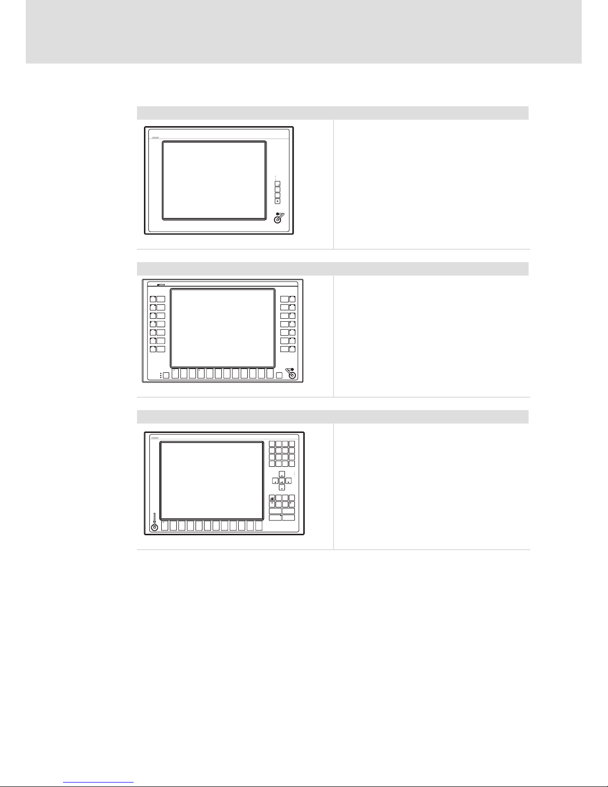
3.3 Device features
MP 800 DVI ... MP 9000 DVI
Design l PC housing of sheet steel
l Front frame of anodised and etched aluminium
l Front made of polyester foil
Mounting l For installation in control cabinets, machine enclosures, and control
boards
Electrical supply l 24 V DC voltage supply
Interfaces l 1 x DVI
l 2 x USB type A (V 2.0)
l 1 x USB type B (V 2.0)
Accessories
ƒ DVI/USB extender
Page 16
Product description
Device features
3
16
BA_MP9000DVI DE 4.0
Overview
Monitor panel MP 800 DVI / MP 1000 DVI / MP 1000s DVI / MP 2000 DVI / MP 5000 DVI / MP 9000 DVI
-
F3
Fail
Power
F1
+
F2
Status
l MP 800 DVI: VGA touchscreen 20.3 cm (8")
MP 1000 DVI: VGA touchscreen 26.4 cm (10.4")
MP 1000s DVI: SVGA touchscreen 26.4 cm (10.4")
MP 2000 DVI: SVGA touchscreen 30.7 cm (12.1")
MP 5000 DVI: XGA touchscreen 38.1 cm (15")
MP 9000 DVI: SXGA touchscreen 48.3 cm (19")
l 3 freely assignable function keys
CS57x0−026
Monitor panel MP 5020 DVI
S13
S14
S11
S10
S12
S6
S7
F3F2
+
-
F4
Status
Power
Fail
F1
Esc
Enter
F11 F12F6F5 F7 F8 F9 F10
S1
S4
S2
S3
S5
S8
S9
l XGA touchscreen 38.1 cm (15")
l 12 freely assignable function keys
l 14 freely assignable special keys
ELx7xx−002
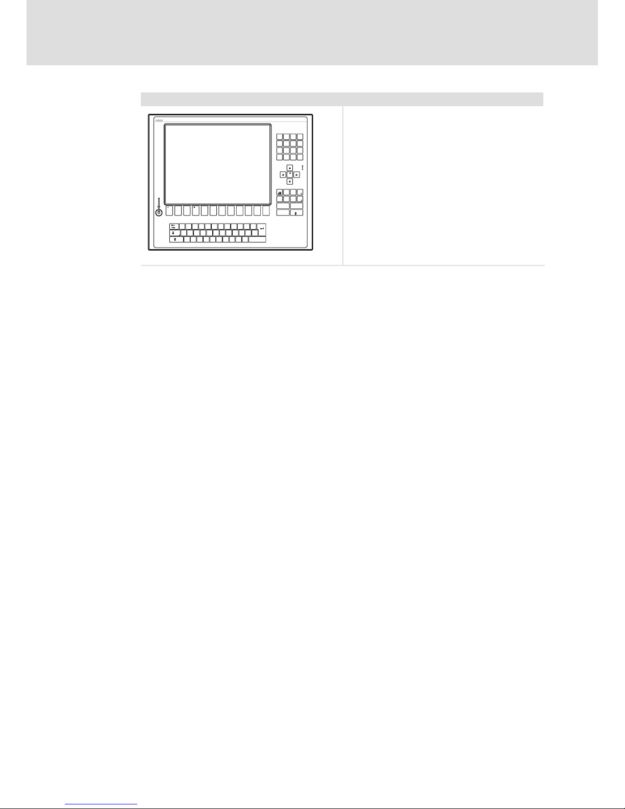
Monitor panel MP 1050 DVI / MP 1050s DVI / MP 2050 DVI / MP 5050 DVI
Q+R
F1 F2 F5
-
ST
F3 F4
@\Z
F11F10YXF9F8 F12
WVU
F7F6
Shift
Alpha
Bs
Space
Enter
EscDelIns
Menu
AltCtrl
Home
1
I
0
M
4
E
7
A
PgDn
*
3
JKL
/
,
NOP
PgUp
End
Status
Power
Fail
2
.
+6
FGH
-
9
BCD
5
8
l MP 1050 DVI: VGA touchscreen 26.4 cm (10.4")
MP 1050s DVI: SVGA touchscreen 26.4 cm (10.4")
MP 2050 DVI: SVGA touchscreen 30.7 cm (12.1")
MP 5050 DVI: XGA touchscreen 38.1 cm (15")
l 12 freely assignable function keys
l Numeric keypad, control keys, level switch−over
Alpha
CS57x0−028
Page 17
Product description
Device features
3
17
BA_MP9000DVI DE 4.0
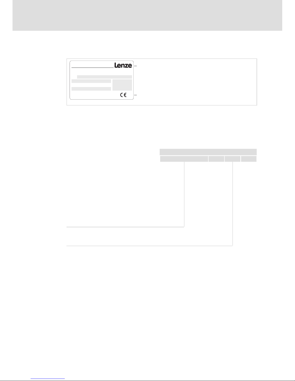
Monitor panel MP 5070 DVI
"
(
§
&
)
=
/
$
!
>
/
*
-
+
,
|
546
879
123
<
0
-
+
Alt Strg
*
+
T
F4
€
D
EWQ
XY
SA
@
F3F1 F2
R
VC
F
F5
GHJ
-
_
Ä
F9F8F6 F7 F10
OIPÜUZ
Ö
;
,
:
M
μ
.
LK
NB
Space
Enter
\?ß
~
F12
Esc
F11
Pos1
Einfg
Ende
Entf
Bs
AltGr
Fail
Status
Power
Bild
Bild
l XGA touchscreen 38.1 cm (15")
l 12 freely assignable function keys
l MF2 keyboard
CS57x0−029
Page 18
Product description
Identification
3
18
BA_MP9000DVI DE 4.0
3.4 Identification
107AT12345
107AT12345
31855 Aerzen; Germany
Made in Germany
Typ e
DVIUSB−012
Type designation
Type code (catalogue/order no.)
Technical data
Customised material number
Bar code with serial number
Manufacturer address
Certification
CE mark
Type code xxxx 2 x 1
5201 = MP 1000 DVI
5202 = MP 1000s DVI
5203 = MP 2000 DVI
5204 = MP 5000 DVI
5205 = MP 9000 DVI
5206 = MP 5020 DVI
5207 = MP 1050 DVI
5208 = MP 1050s DVI
5209 = MP 2050 DVI
5210 = MP 5050 DVI
5211 = MP 5070 DVI, keyboard layout German
5212 = MP 5070 DVI, keyboard layout English
5213 = MP 800 DVI
Front face USB socket
0 = without
1 = with (IP65)
Page 19
Product description
Controls and displays
3
19
BA_MP9000DVI DE 4.0
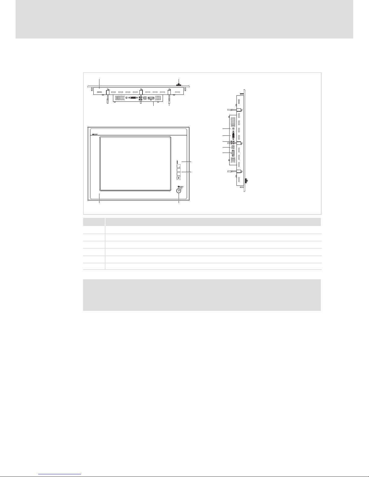
3.5 Controls and displays
-
F3
Fail
Power
F1
+
F2
Status
10
0 1
5
4
3
2
+
DVI
USB-A
USB-B
24 V DC
0V U
0V U
MP9000DVI−001
Pos. Description
Monitor panel (here MP 5000 DVI)
Front face USB port (option)
Screw clamp fixings
Nameplate
Status LEDs (Power, Fail, Status)
Front face control and display elements
Note!
Further information on the control and display elements can be gathered from
the chapter "Operation" ( 32).
Page 20
Technical data
General data and operating conditions
4
20
BA_MP9000DVI DE 4.0
4 Technical data
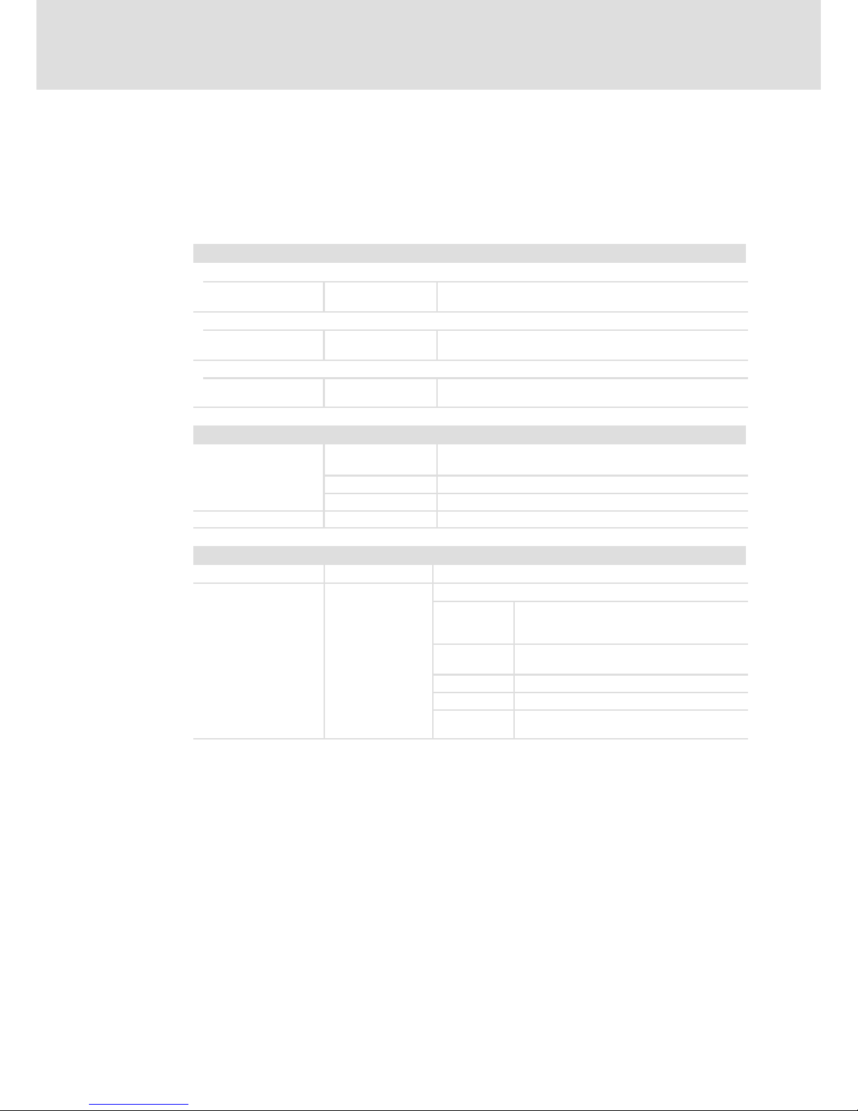
4.1 General data and operating conditions
General data
Conformity and approval
Conformity
CE
EN 61000−6−4
EN 61000−6−2
EMC Directive Class A, industrial premises
Approbation
UR UL 508
CSA C22.2
Programmable Controllers (File−No. E236341)
Other
RoHS − Products lead−free in accordance with CE Directive
2011/65/EU
Protection of persons and equipment
Safety VDE0805 (EN60950),
VDE0870, UL
Enclosure EN 60529 IP65 (front) / IP20 (back)
UL 508 (NEMA 250) Type 1 enclosure
Class of protection 3
EMC
Noise emission EN 61000−6−4
Class A (industrial premises)
Noise immunity zone B EN 61000−6−2
Industrial premises
EN 61000−4−2 ESD; severity level 3, i. e.
8 kV for air discharge,
4 kV for contact discharge
EN 61000−4−3 RF interference (housing)
80 MHz 1000 MHz, 10 V/m 80 % AM (1 kHz)
EN 61000−4−4 Burst, severity level 3
EN 61000−4−5 Surge, severity level 1 *
EN 61000−4−6 RF cable−guided
150 kHz 80 MHz, 10 V/m 80 % AM (1 kHz)
* Due to the high−energy single current pulses, surges require suitable external wiring with lightning protection
elements like for example lightning conductors and overvoltage arresters.
Page 21
Technical data
General data and operating conditions
4
21
BA_MP9000DVI DE 4.0
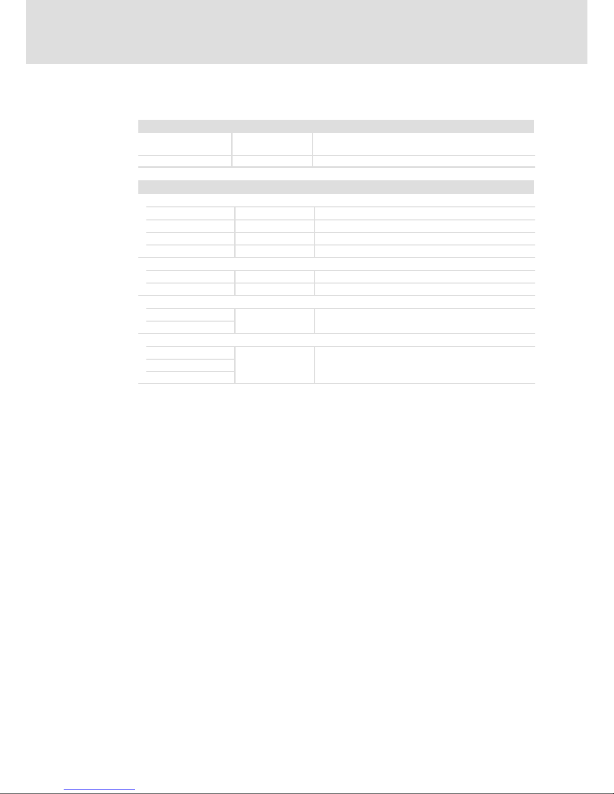
Operating conditions
Mounting conditions
Place of installation
In the control cabinet, screen protected against direct solar
radiation
Mounting position Connections at the bottom
Ambient conditions
Climatic
Storage
−10 ... +60 °C
Transport −10 ... +60 °C
Operation +5 ... +45 °C
Relative humidity 10 ... 90 %, non−condensing
Site altitude
StoragetTransport < 12000 m amsl
Operation < 3000 m amsl
Chemical resistance
Decor film
DIN 42115
Touch/display
Mechanical load capacity
Decor film
DIN 42115 max. 100 N
Touch/display
Switching element
Page 22
Technical data
Electrical data
4
22
BA_MP9000DVI DE 4.0
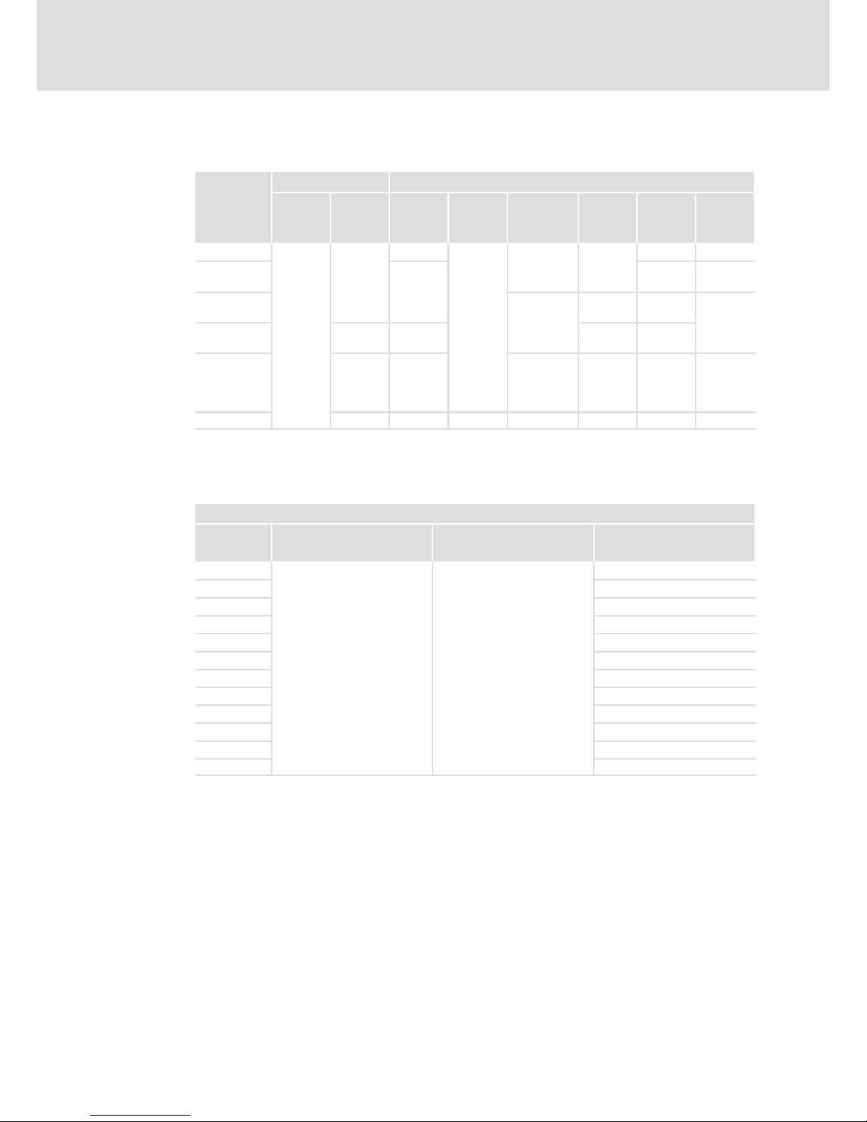
4.2 Electrical data
Supply Screen
Voltage Current at
24 V
Visible
size
Aspect
ratio
Resolution Brightness Contrast MTBF
[V DC] [A] [cm] [pixels] [cd/m2] [h]
MP 800 DVI
24
(+18 ... 30)
0.4
20.3 (8")
4:3
640 x 480 400
1 : 250 50 000
MP 1000 DVI
MP 1050 DVI
26.4
(10.4")
1 : 300 40 000
MP 1000s DVI
MP 1050s DVI
800 x 600
400 1 : 500
50 000
MP 2000 DVI
MP 2050 DVI
0.7
30.5
(12.1")
300 1 : 200
MP 5000 DVI
MP 5020 DVI
MP 5050 DVI
MP 5070 DVI
0.9 38.1 (15") 1024 x 768 250 1 : 550 40 000
MP 9000 DVI 1.4 48.3 (19") 5:4 1280 x 1024 300 1 : 2000 50 000
4.3 Mechanical data
Versions and weights
Front frame / housing Touchscreen Mass
[kg]
MP 800 DVI
Aluminium/sheet steel
Polyester foil
3.0
MP 1000 DVI
4.2
MP 1000s DVI
4.2
MP 1050 DVI
4.6
MP 1050s DVI
4.6
MP 2000 DVI
5.4
MP 2050 DVI
5.6
MP 5000 DVI
6.2
MP 5020 DVI
6.4
MP 5050 DVI
6.4
MP 5070 DVI
7.2
MP 9000 DVI
10.2
Page 23
Technical data
Mechanical data
4
23
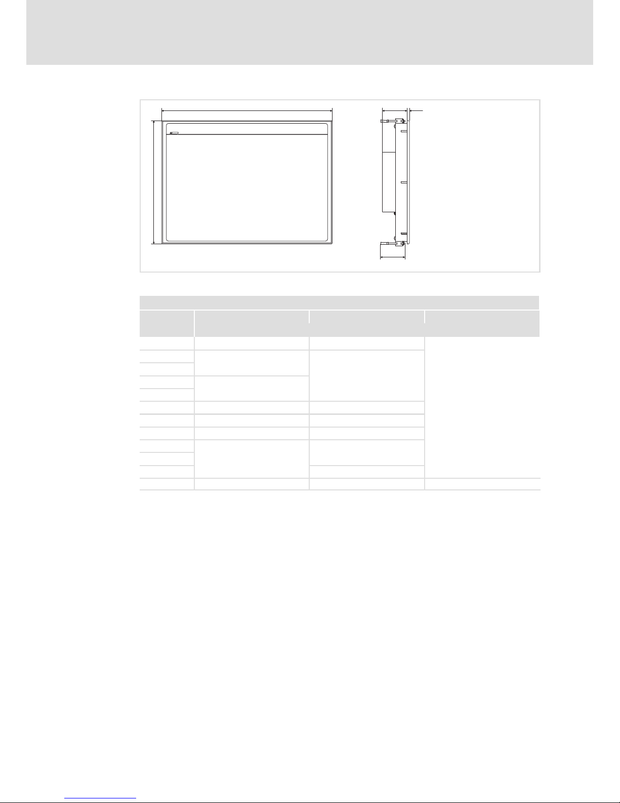
BA_MP9000DVI DE 4.0
a
b
6e
65
MP9000DVI−003
All dimensions in millimetres.
Dimensions
a b e
[mm]
MP 800 DVI
265
200
59
MP 1000 DVI
325
240
MP 1000s DVI
MP 1050 DVI
365
MP 1050s DVI
MP 2000 DVI
390 300
MP 2050 DVI
425 310
MP 5000 DVI
450 325
MP 5020 DVI
483
310 (7 U)
MP 5050 DVI
MP 5070 DVI
399 (9 U)
MP 9000 DVI 490 400 69
Page 24

Mechanical installation
Important notes
5
24
BA_MP9000DVI DE 4.0
5 Mechanical installation
5.1 Important notes
The installation must be carried out by qualified, skilled personnel familiar with the
applicable national standards.
Stop!
Sensitive front frame gasket
During mounting, the gasket of the front frame is exposed and can be
damaged.
Possible consequences:
ƒ The degree of protection provided by the enclosure mentioned in the
technical data is not attained.
Protective measures:
ƒ Handle the gasket with care during mounting.
ƒ Protect the gasket against ultraviolet rays.
ƒ Each time before you mount the device, check whether the gasket is intact.
Stop!
Sensitive touchscreen surface
The touchscreen foil is very sensitive to external forces and can be damaged by
improper handling.
Possible consequences:
ƒ The touchscreen foil becomes damaged, scratched or dull.
Protective measures:
ƒ Avoid contact of the touchscreen foil with pointed or hard objects.
ƒ Always use a touch pen or your fingers to operate the touchscreen. Never
use objects such as ballpoint pens, pencils, etc.
ƒ When removing dirt and fingerprints, observe the notes given in the chapter
"Cleaning" ( 38).
Note!
When selecting the place where the PC is to be installed, pay attention to an
ergonomic positioning of the screen and to the incidence of light which might
cause reflections on the screen.
Page 25
Mechanical installation
Mounting cutout
5
25
BA_MP9000DVI DE 4.0
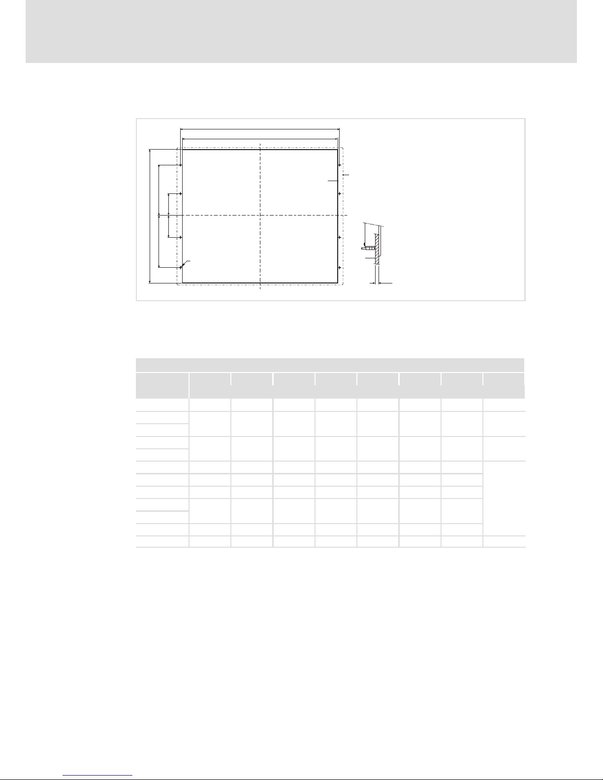
5.2 Mounting cutout
0
1
a1
a2
£ 5
2
b1
b2
b3
b5
b4
D
ELx7xx−004
Mounting cutout
Outline of front panel
Control board
All dimensions in millimetres.
Dimensions
a1 a2 b1 b2 b3 b4 b5 D
[mm]
MP 800 DVI 246 − 188 − − − − −
MP 1000 DVI
305.0 − 228.0 − − − − −
MP 1000s DVI
MP 1050 DVI
343.0 − 228.0 − − − − −
MP 1050s DVI
MP 2000 DVI
340.0 351.0 288.0 122.0 122.0 0.0 −
6 x Æ5.5
MP 2050 DVI
375.0 386.0 288.0 122.0 122.0 0.0 −
MP 5000 DVI
400.0 411.0 313.0 134.5 134.5 0.0 −
MP 5020 DVI
452.0 462.4 299.0 104.9 104.6 15.7 −
MP 5050 DVI
MP 5070 DVI
452.0 462.4 388.2 149.3 149.3 15.9 −
MP 9000 DVI 438.0 451.0 386.0 172.0 172.0 60.0 60.0 8 x Æ4.5
Page 26
Mechanical installation
Mounting steps
MP 1000(s) DVI / MP 1050(s) DVI
5
26
BA_MP9000DVI DE 4.0
5.3 Mounting steps
5.3.1 MP 1000(s) DVI / MP 1050(s) DVI
How to perform the installation:
1. Cut the mounting cutout into the control board ( 25).
2. Check that the gasket under the front panel is located correctly.
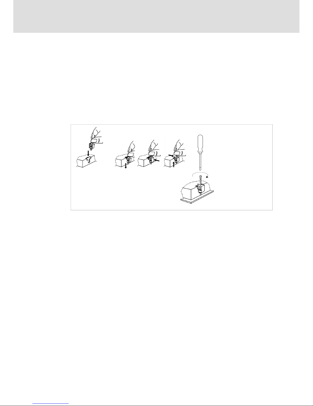
3. Place the device in the mounting cutout and secure it against falling−down with one
hand.
4. Fit all screw clamp fixings as explained below:
ELx7xx−011
– Insert the screw clamp fixing into the slot in the housing of the device (see above
figure).
– Press the screw clamp fixing downwards, tilt it towards the housing and check
that it has firmly snapped into place.
– Tighten the screw clamp fixing hand−tight with a screwdriver.
5. Check that the device is securely located in the mounting cutout and that the front
panel gasket is located correctly.
– If necessary, realign the device/gasket.
– If the gasket is not located correctly, protection class IP65 is not achieved on the
front of the device!
Page 27
Mechanical installation
Mounting steps
MP 2xxx DVI / MP 5xxx DVI / MP 9xxx DVI
5
27
BA_MP9000DVI DE 4.0
5.3.2 MP 2xxx DVI / MP 5xxx DVI / MP 9xxx DVI
Note!
Types MP 5020 DVI, MP 5050 DVI, and MP 5070 DVI can be installed in any
control panel and in 19" mounting racks in accordance with DIN 41494.
Control board mounting
How to perform the installation:
1. Prepare the control board by cutting the mounting cutout and drilling the mounting
holes into it ( 25).
2. Check that the gasket under the front panel is located correctly.
3. Place the device in the mounting cutout, secure it by hand against falling down and
screw the nuts and washers onto the threaded bolts.
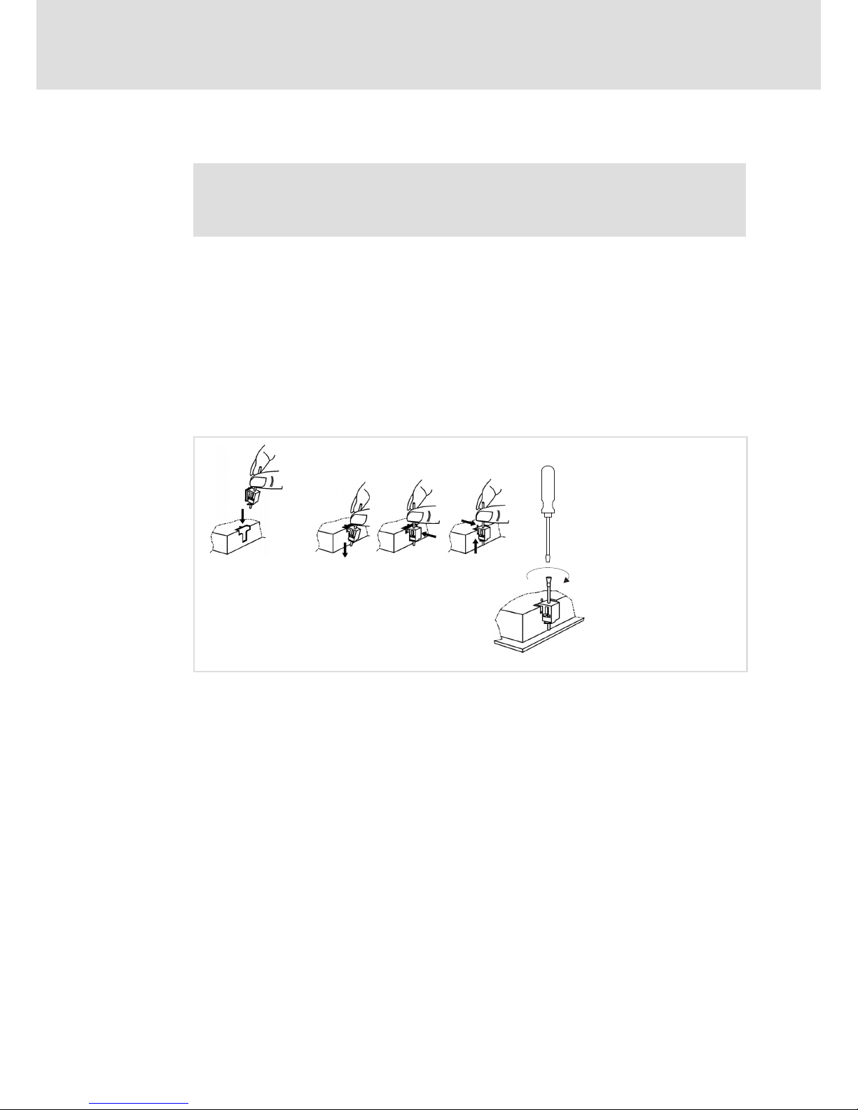
4. Fit all screw clamp fixings as explained below:
ELx7xx−012
– Insert the screw clamp fixing into the slot in the housing of the device (see above
figure).
– Press the screw clamp fixing downwards, tilt it towards the housing and check
that it has firmly snapped into place.
– Tighten the screw clamp fixing hand−tight with a screwdriver.
5. Check that the device is securely located in the mounting cutout and that the front
panel gasket is located correctly.
– If necessary, realign the device/gasket.
– If the gasket is not located correctly, protection class IP65 is not achieved on the
front of the device!
19" mounting rack installation (only MP 5020 DVI, MP 5050 DVI, and MP 5070 DVI)
How to perform the installation:
1. Remove the set screws from the back of the front frame.
2. Drill through the blind holes at the back of the front frame using a 6.5 mm drill.
3. Place the device in the 19" mounting rack and screw it.
Page 28

Electrical installation
Important notes
6
28
BA_MP9000DVI DE 4.0
6 Electrical installation
6.1 Important notes
The installation must be carried out by qualified, skilled personnel familiar with the
applicable national standards.
Stop!
Short circuit and static discharge
The device contains components which are endangered in the case of short
circuit or static discharge.
Possible consequences:
ƒ The device or parts of it will be destroyed.
Protective measures:
ƒ Always switch off the voltage supply when working on the device. This
particularly applies:
– Before connecting / disconnecting connectors.
– Before plugging in / plugging out modules.
ƒ All persons handling printed circuit boards have to take account of ESD
measures.
ƒ Contacts of plug connectors must not be touched.
ƒ Printed circuit boards may be touched only at places free from electrical
contacts and may be placed only on appropriate materials (e.g. on ESD
packaging or conductive foam material).
ƒ Printed circuit boards may only be transported and stored in ESD packaging.
Page 29

Electrical installation
Wiring according to EMC
6
29
BA_MP9000DVI DE 4.0
6.2 Wiring according to EMC
General notes l The electromagnetic compatibility of the system depends on the type and accuracy of the
installation. Please especially note the following:
– Structure
– Shielding
– Earthing
l In the case of a differing installation it is required for evaluating the conformity to the EMC
Directive to check the system with regard to compliance with the EMC limit values. This for
instance applies to:
– The use of unshielded cables
l The end user is responsible for compliance with the EMC Directive.
– If you observe the following measures, you can be sure that no EMC problems will occur
during operation and that the EMC Directive or the EMC law is met.
– If devices which do not meet the CE requirement with regard to noise immunity
EN 61000−4−2 are actuated near the system, these devices can be affected
electromagnetically by the system.
Structure l Connect device to the earthed mounting plate:
– Mounting plates with an electroconductive surface (zinc−coated or stainless steel) allow for
continuous contacting.
– Coated plates are not suitable for an EMC−compliant installation.
l If you use several mounting plates:
– Connect mounting plates to each other on a large surface and in a conductive manner (e.g.
by means of copper strips).
l When installing the cables, observe a spatial separation of signal and mains cables.
l Route the cables as near to the reference potential as possible. Freely suspended cables act
like aerials.
Shielding l Preferably only use cables with a braid.
l The coverage of the shield should be more than 80%.
l In the case of data lines for a serial coupling, always use metallic or metallised plugs. Connect
the shield of the data line on the connector shell.
Earthing l Earth all metallically conductive components by the use of corresponding cables from a
central earthing point (PE rail).
l Comply with the minimum cross−sections defined in the safety instructions:
– With regard to EMC, however, not the cable cross−section, but the surface of the cable and
of the extensive contacting is decisive.
Page 30
Electrical installation
Connecting the supply and peripheral devices
Terminal diagram supply
6
30
BA_MP9000DVI DE 4.0
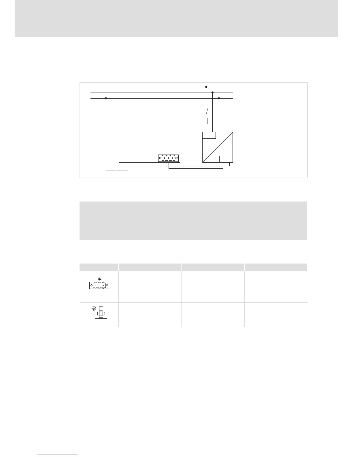
6.3 Connecting the supply and peripheral devices
6.3.1 Terminal diagram supply
L1
N
PE
L1
N
+
0V
+24
+
~ =
0 V
PE+24 V
+
0
1
F
S
MP9000DVI−006
Monitor panel
Power supply unit
Note!
Observe the max. permissible input voltage.
Professionally fuse the device on the input side against voltage variations and
voltage peaks.
6.3.2 24 V connection
Description Connection type Cable type
0V U
DC 24 V connection
3−pole Phoenix Combicon
socket
Cable (conductor
cross−section max. 2.5 mm
2
)
with Phoenix Combicon plug,
MSTB 2.5 / 3−STF−5.08
IPC001
PE connection M4 threaded bolt
Separate earthing conductor
(min. 2.5 mm
2
) with ring
cable lug
IPC001
Page 31
Electrical installation
Connecting the supply and peripheral devices
DVI interface
6
31
BA_MP9000DVI DE 4.0
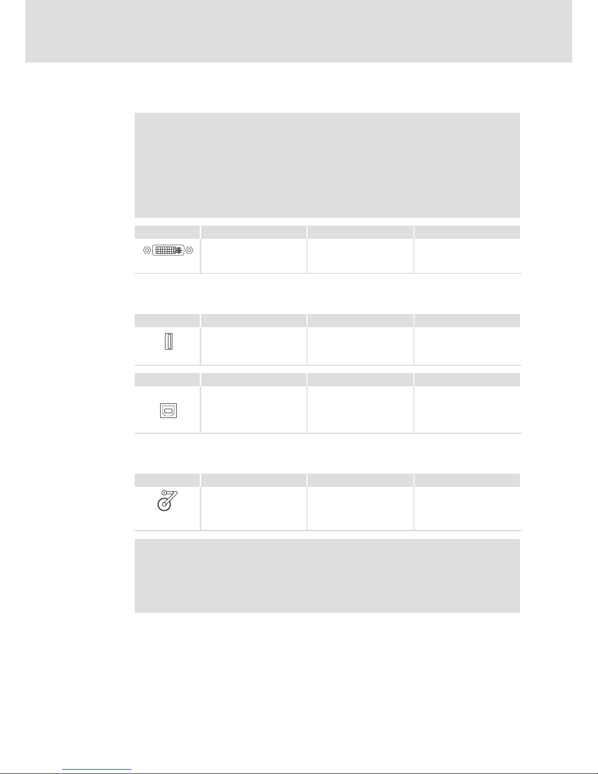
6.3.3 DVI interface
Note!
Only use the DVI cable from the scope of supply or one of the DVI cables
specified in the following table, featuring a maximum length of 2 m.
Otherwise a faultless signal transmission is not guaranteed.
Greater distances can be covered with the following Lenze accessories:
2 ... 5 m: "DVI/USB" cable set
5 ... 35 m: DVI/USB extender V4
Description Connection type Cable type
DVI interface DVI−D socket
DVI−D single link (18+1)
DVI−D double link (24+1)
IPC001
6.3.4 USB interface
Description Connection type Cable type
USB 2.0 host connection
Max. load: 5 V/500 mA
USB−A socket USB cable with USB−A plug
IPC001
Description Connection type Cable type
USB
USB device connection USB−B socket USB cable with USB−B plug
DVI/USB−010
6.3.5 USB interface on the front face (option)
Description Connection type Cable type
USB 2.0 host connection with
IP 65 cover
Max. load: 5 V/500 mA
USB−A socket USB cable with USB−A plug
EL100−013
Note!
If you use USB interfaces routed to the outside, the data integrity cannot be
guaranteed. On the "PC based Automation" DVD you’ll find the "FM Tool"
software which can be used to deactivate the front USB interface if it is not
needed.
Page 32

Operation
Important notes
7
32
BA_MP9000DVI DE 4.0
7 Operation
7.1 Important notes
Stop!
Sensitive touchscreen surface
The touchscreen foil is very sensitive to external forces and can be damaged by
improper handling.
Possible consequences:
ƒ The touchscreen foil becomes damaged, scratched or dull.
Protective measures:
ƒ Avoid contact of the touchscreen foil with pointed or hard objects.
ƒ Always use a touch pen or your fingers to operate the touchscreen. Never
use objects such as ballpoint pens, pencils, etc.
ƒ When removing dirt and fingerprints, observe the notes given in the chapter
"Cleaning" ( 38).
Page 33
Operation
Controls and displays
Monitor Panel MP 800 DVI / MP 1000 DVI / MP 1000s DVI / MP 2000 DVI /
7
33
BA_MP9000DVI DE 4.0
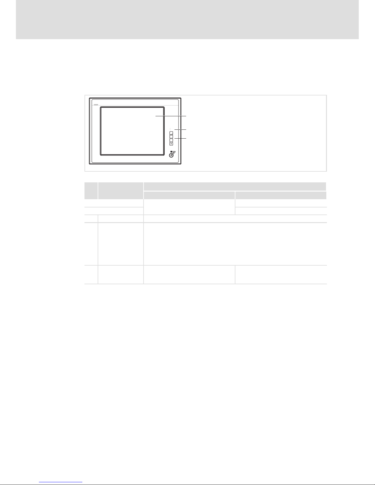
7.2 Controls and displays
7.2.1 Monitor Panel MP 800 DVI / MP 1000 DVI / MP 1000s DVI / MP 2000 DVI /
MP 5000 DVI / MP 9000 DVI
-
F3
Fail
Power
F1
+
F2
Status
1
2
0
CS50x0−022
Pos. Designation
Function
Standard mode Service mode
Switch on mode: Press "" for 4 s
Switch off mode: Press "" or wait for 35 s
Display Application−dependent
Status LEDs Power (green):
l Is ON when the supply voltage is present.
Fail (red):
l Is On when a power supply failure has occurred.
l Is blinking when the screen signal is missing.
Status (yellow):
l Application−dependent
Function keys F1 ... F3: Send key code for Shift−F1 ...
Shift−F3
Tool: Application−dependent
+: Increase screen brightness
−: Reduce screen brightness
Page 34
Operation
Controls and displays
Panel MP 5020 DVI
7
34
BA_MP9000DVI DE 4.0
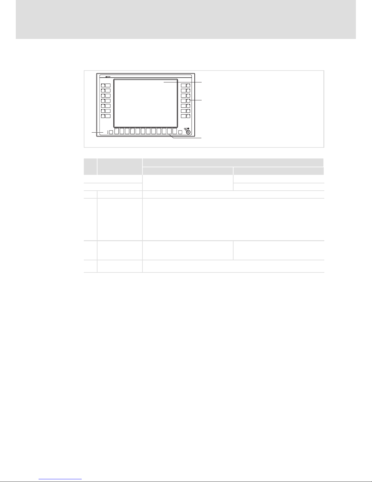
7.2.2 Monitor Panel MP 5020 DVI
5
2
0
S13
S14
S11
S10
S12
S6
S7
F3F2
+
-
F4
Status
Power
Fail
F1
Esc
Enter
F11 F12F6F5 F7 F8 F9 F10
S1
S4
S2
S3
S5
S8
S9
1
MP9000DVI_010
Pos. Designation
Function
Standard mode Service mode
Switch on mode: Press "" for 4 s
Switch off mode: Press "" or wait for 35 s
Display Application−dependent
Status LEDs Power (green):
l Is ON when the supply voltage is present.
Fail (red):
l Is On when a power supply failure has occurred.
l Is blinking when the screen signal is missing.
Status (yellow):
l Application−dependent
Function keys F1 ... F12: Send key code for F1 ... F12 Tool: Application−dependent
+: Increase screen brightness
−: Reduce screen brightness
Special keys S1 ... S7: Send key code for shift−F1 ... shift−F7
S8 ... S14: Send key code for ctrl−F1 ...ctrl−F7
Page 35
Operation
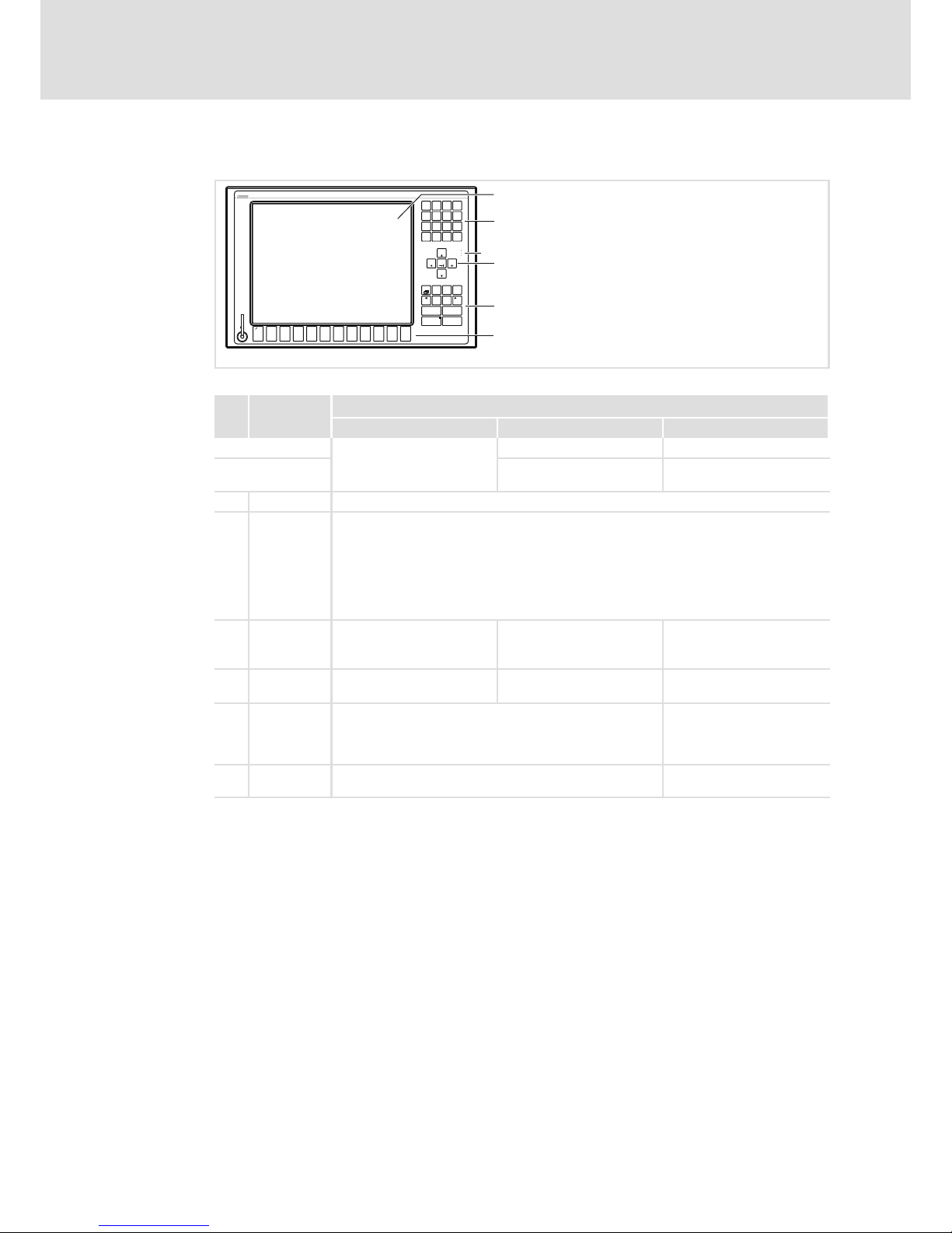
Controls and displays
Monitor Panel MP 1050 DVI / MP 1050s DVI / MP 2050 DVI / MP 5050 DVI
7
35
BA_MP9000DVI DE 4.0
7.2.3 Monitor Panel MP 1050 DVI / MP 1050s DVI / MP 2050 DVI / MP 5050 DVI
Q+R
F1 F2 F5
-
ST
F3 F4
@\Z
F11F10YXF9F8 F12
WVU
F7F6
Shift
Alpha
Bs
Space
Enter
EscDelIns
Menu
AltCtrl
Home
1
I
0
M
4
E
7
A
Pg Dn
*
3
JKL
/
,
NOP
Pg Up
End
Status
Power
Fail
2
.
+6
FGH
-
9
BCD
5
8
3
4
5
2
1
0
CS50x0−024
Pos. Designation
Function
Standard mode Alpha mode Service mode
Switch on mode: Press "alpha key" (LED is on) Press "menu key"
Switch off mode: Press "alpha key" (LED is off) Press "menu key" or wait for
35 s
Display Application−dependent
Status LEDs Power (green):
l Is ON when the supply voltage is present.
Fail (red):
l Is ON when a power supply failure has occurred
l Is blinking when the screen signal is missing.
Status (yellow):
l Indicates access to a storage medium.
Function keys F1 ... F12: Send key code for
Shift−F1 ... Shift−F12
F1 ... F12: Send key codes for
"Q" ... "@"
Tool: Application−dependent
+: Increase screen brightness
−: Reduce screen brightness
Numeric
keypad
Send key codes for "0" ... "9"
and calculation operators
Send key codes for "A" ... "P" Functionality same as in
standard/alpha mode
Cursor keys Without "Shift" key: Move cursor/marker in steps and set
tab
With "Shift" key: Move cursor/marker to the beginning/end
or page by page
Functionality same as in
standard/alpha mode
Control keys Standard functions of a MF2 keyboard
(For "alpha" and "menu" see "Switch on/off mode")
Functionality same as in
standard/alpha mode
Page 36
Operation
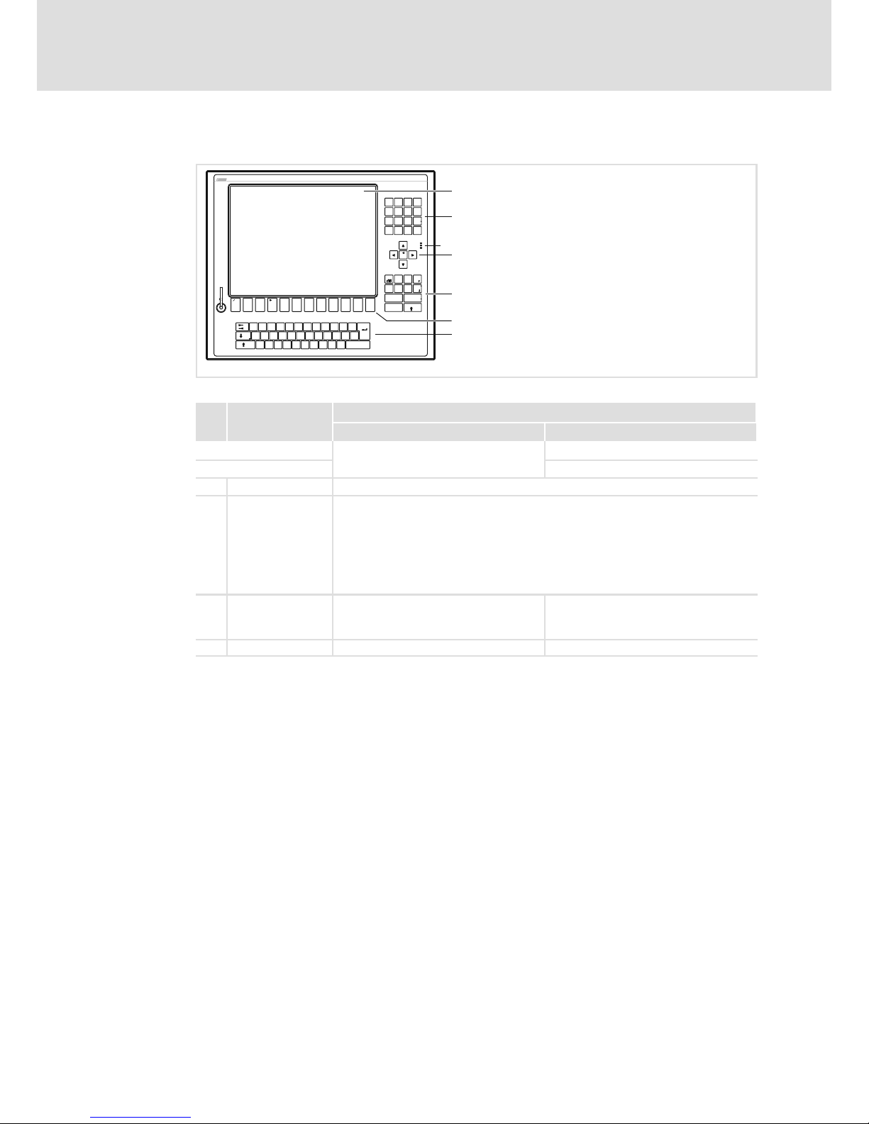
Controls and displays
Monitor Panel MP 5070 DVI
7
36
BA_MP9000DVI DE 4.0
7.2.4 Monitor Panel MP 5070 DVI
3
3
"
(
§
&
)
=
/
$
!
>
/
*
-
+
,
|
546
879
123
<
0
-
+
Alt Strg
*
+
T
F4
€
D
EWQ
XY
SA
@
F3F1 F2
R
VC
F
F5
GHJ
-
_
Ä
F9F8F6 F7 F10
OIPÜUZ
Ö
;
,
:
M
μ
.
LK
NB
Space
Enter
\?ß
~
F12
Esc
F11
Pos 1
Einfg
Ende
Entf
Bs
Alt Gr
Fail
Status
Power
Bild
Bild
3
3
2
1
0
CS50x0−025
Pos. Designation
Function
Standard mode Service mode
Switch on mode: Press " (F4)" for 4 s
Switch off mode: Press " (F4)" or wait for 35 s
Display Application−dependent
Status LEDs Power (green):
l Is ON when the supply voltage is present.
Fail (red):
l Is ON when a power supply failure has occurred.
l Is blinking when the screen signal is missing.
Status (yellow):
l Indicates access to a storage medium.
Function keys F1 ... F12: Send key code for Shift−F1 ...
Shift−F12
Tool: Application−dependent
+: Increase screen brightness
−: Reduce screen brightness
MF2 keys Standard function of a MF2 keyboard
Page 37

Maintenance
Regular checks
8
37
BA_MP9000DVI DE 4.0
8 Maintenance
Stop!
Short circuit and static discharge
The device contains components which are endangered in the case of short
circuit or static discharge.
Possible consequences:
ƒ The device or parts of it will be destroyed.
Protective measures:
ƒ Always switch off the voltage supply when working on the device. This
particularly applies:
– Before connecting / disconnecting connectors.
– Before plugging in / plugging out modules.
ƒ All persons handling printed circuit boards have to take account of ESD
measures.
ƒ Contacts of plug connectors must not be touched.
ƒ Printed circuit boards may be touched only at places free from electrical
contacts and may be placed only on appropriate materials (e.g. on ESD
packaging or conductive foam material).
ƒ Printed circuit boards may only be transported and stored in ESD packaging.
8.1 Regular checks
The device is free of maintenance. Nevertheless, visual inspections should be carried out
at regular intervals which must not be too long, depending on the ambient conditions.
Please check the following:
ƒ Does the environment of the device meet the operating conditions specified in the
Technical data?
ƒ Is the heat dissipation of the device not impeded by dust or dirt?
ƒ Are the mechanical and electrical connections o.k.?
Page 38

Maintenance
Cleaning
8
38
BA_MP9000DVI DE 4.0
8.2 Cleaning
Stop!
Sensitive surfaces and components
The device can be damaged if it is not appropriately cleaned.
Possible consequences:
ƒ The housing or the screen gets scratched or dull if you use alcoholic,
solvent−containing or scouring cleaning agents.
ƒ Electrical components can be damaged ...
– by a short circuit caused by humidity.
– by static discharge.
Protective measures:
ƒ Observe the following notes.
ƒ Before cleaning, disconnect the device from the power supply as otherwise
unintentional commands may be activated via the touchscreen, for example a
response of the control.
ƒ Clean the device front (screen and frame) as follows:
– Use a clean, lint−free and soft cloth.
– Moisten the cloth with the detergent. Do not spray the detergent directly on the
device.
– Only use water with a fluid addition as detergent or a detergent declared
especially for flat screens.
ƒ Clean the rear side of the device with a clean, lint−free and soft cloth. Do not use
liquid or foaming detergent since it may enter the housing or terminals.
Page 39
Maintenance
Repair
Removing and mounting the housing
8
39
BA_MP9000DVI DE 4.0
8.3 Repair
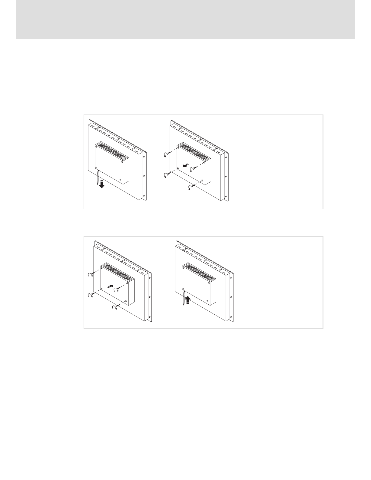
For the repair of the monitor panel, its housing has to be removed.
8.3.1 Removing and mounting the housing
Dismounting
24 V DC
MP9000DVI−015
Mounting
24 V DC
MP9000DVI−016
Page 40
Maintenance
Repair
Fuse change
8
40
BA_MP9000DVI DE 4.0
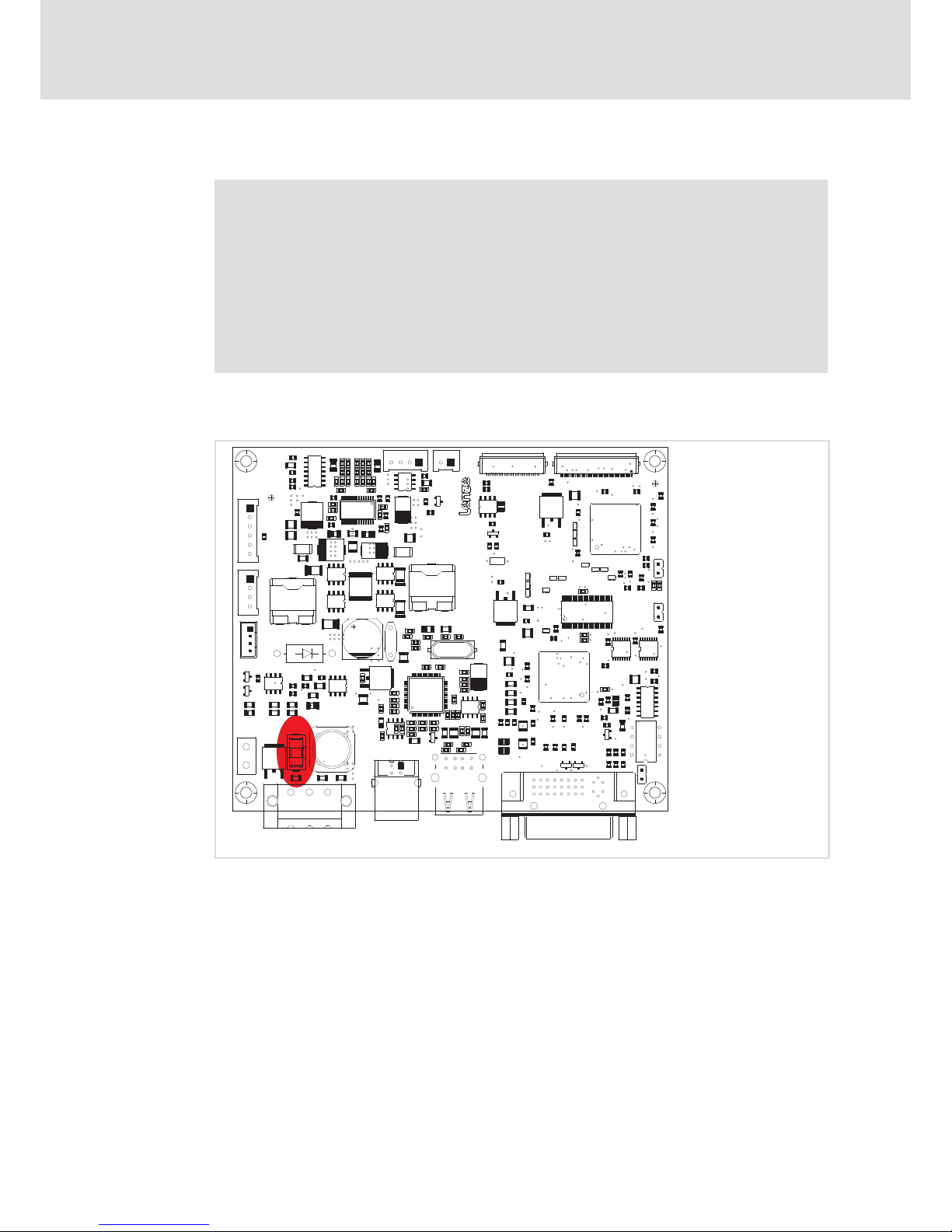
8.3.2 Fuse change
Stop!
Damage of the device by non−permissible fuse possible
The baseboard in the device is protected by a fuse which will be damaged if
the supply voltage applied is too high.
Possible consequences:
ƒ The device can be damaged if a non−approved fuse is installed.
Protective measures:
ƒ The fuse may only be replaced by an approved type.
Approved types:
ƒ Wickmann No. 181, 4 A, 250 V DC
DOWNLOAD
FAN
2xUSB
DVI
POWER-INPUT
USBUPSTREAM
POWER
BACKLIGHT
POWER
MPE-01
123
123
123
123
1
8
1
4
1
24
17
9
CS50x0−018
Fig. 8−1 Position of the fuse on the baseboard
Page 41

Index 9
41
BA_MP9000DVI DE 4.0
9 Index
A
Ambient conditions
− climatic, 21
− Site altitude, 21
− Chemical resistance, 21
Application as directed, 15
Approbation, 20
C
Chemical resistance, 21
Class of protection, 20
Cleaning, 38
Conformity, 20
Control elements
− MP 1000(s) DVI, 33
− MP 1050(s) DVI, 35
− MP 2000 DVI, 33
− MP 2050 DVI, 35
− MP 5000 DVI, 33
− MP 5020 DVI, 34
− MP 5050 DVI, 35
− MP 5070 DVI, 36
− MP 800 DVI, 33
− MP 9000 DVI, 33
Controls, 19, 33
D
Danger
− Short circuit, 28, 37
− Static discharge, 28, 37
Definition of notes used, 8
Device
− control and display elements
MP 1000(s) DVI, 33
MP 1050(s) DVI, 35
MP 2000 DVI, 33
MP 2050 DVI, 35
MP 5000 DVI, 33
MP 5020 DVI, 34
MP 5050 DVI, 35
MP 5070 DVI, 36
MP 800 DVI, 33
MP 9000 DVI, 33
− overview, 19
− radio interference, 11
− version, 22
− weight, 22
Display, 22
Display elements
− MP 1000(s) DVI, 33
− MP 1050(s) DVI, 35
− MP 2000 DVI, 33
− MP 2050 DVI, 35
− MP 5020 DVI, 34
− MP 5050 DVI, 35
− MP 5070 DVI, 36
− MP 800 DVI, 33
− MP 9000 DVI, 33
Displays, 19, 33
Disposal, 11
DVI port, 31
E
Electrical data, 22
Electrical installation, 28
− EMC−compliant wiring, 29
− Mains, 30
− monitor, 31
− Terminal diagram, 30
− USB
front panel, 31
internal, 31
− USB connection, 31
EMC, 20
− earthing, 29
− shielding, 29
− structure, 29
EMC−compliant wiring, 29
Enclosure, 20
Ergonomics, 11
Error behaviour, 11
F
Fault, behaviour, 11
Fuse, change, 40
G
General data, 20
I
Identification, 18
Installation, CE−typical drive system
− earthing, 29
− shielding, 29
− structure, 29
Installation, electrical, 28
Installation, mechanical, 24
L
Load capacity, 21
M
Mains connection, 30
Maintenance, 37
− Cleaning, 38
− Fuse, 40
− Regular checks, 37
− Repair, 39
Mechanical data, 22
− version, device, 22
− weight, device, 22
Mechanical installation, 24
Mechanical load capacity, 21
Monitor connection, 31
Monitor port, 31
Mounting conditions
− Mounting position, 21
− Place of installation, 21
Mounting cutout, 25
Mounting steps
− 19 mounting rack installation, 27
− control panel mounting, 26, 27
Mounting the housing, 39
N
Nameplate, 18
Nameplate data, 18
Noise emission, 20
Noise immunity, 20
Notes, definition, 8
Page 42

Index9
42
BA_MP9000DVI DE 4.0
O
Operating conditions, 21
− mounting conditions
Mounting position, 21
Place of installation, 21
Operation, 32
Overview, 19
P
Product description, 14
− application as directed, 15
R
Radio interference, 11
Regular checks, 37
Removing the housing, 39
Repair, 39
S
Safety, 20
Safety instructions, 9
− application as directed, 15
− definition, 8
− layout, 8
Scope of supply, 14
Screen, 22
Shielding, EMC, 29
Short circuit, 28, 37
Site altitude, 21
Static discharge, 28, 37
Supply, 22
T
Technical data, 20
− Electrical data, 22
− General data, 20
− mechanical data, 22
− Mounting cutout, 25
− Operating conditions, 21
Temperatures, 21
Terminal diagram, 30
Touchscreen, 22
Type code, 18
− finding, 18
U
USB connection, 31
− front panel, 31
− internal, 31
V
Validity, documentation, 5
Version, device, 22
Voltage supply, 22
W
Weight, device, 22
Page 43

© 02/2014
F
Lenze Automation GmbH
Postfach 10 13 52, D−31763 Hameln
Hans−Lenze−Str. 1, D−31855 Aerzen
Germany
Service Lenze Service GmbH
Breslauer Straße 3, D−32699 Extertal
Germany
(
+495154 82−0
(
0080002446877 (24 h helpline)
Ê
+495154 82−2800
Ê
+49515482−1112
ü
www.lenze.com
BA_MP9000DVI § .NpW § DE § 4.0 § TD06
10987654321
 Loading...