

Page 1
MC Series Drives
Modbus Communications Reference Guide
Page 2

About These Instructions
This documentation applies to the use of an MC 1000 Series and an MC 3000 Series Variable Frequency Drive
in a Modbus Network and should be used in conjunction with the MC Series Installation and Operation Manual
(Document M101 or M301, respectively) that shipped with the drive. These documents should be read in their
entirety as they contain important technical data and describe the installation and operation of the drive.
© 2003 Lenze AC Tech Corporation
No part of this documentation may be copied or made available to third parties without the explicit written approval
of Lenze AC Tech Corporation. All information given in this documentation has been carefully selected and tested
for compliance with the hardware and software described. Nevertheless, discrepancies cannot be ruled out. Lenze
AC Tech does not accept any responsibility nor liability for damages that may occur. Any necessary corrections will
be implemented in subsequent editions.
Page 3

Contents
1 Safety Information .............................................................................................................1
1.1 Warnings, Cautions and Notes ..............................................................................1
1.1.1 General ....................................................................................................1
1.1.2 Application ...............................................................................................1
1.1.3 Installation ...............................................................................................1
1.1.4 Electrical Connection ................................................................................2
1.1.5 Operation .................................................................................................2
1.2 Reference and Links .............................................................................................2
2 Introduction .......................................................................................................................3
2.1 Modbus Details .....................................................................................................3
2.2 Universal Registers ...............................................................................................4
3 Data Representation - Internal and External .......................................................................5
3.1 Register Format ....................................................................................................5
3.2 Data Types ...........................................................................................................5
3.3 AC Tech Drive Registers........................................................................................5
4 MC Drive Setup & Operation ..............................................................................................6
4.1 Serial Address ......................................................................................................6
4.2 Serial Communications Parameter ........................................................................6
4.3 Control Parameter .................................................................................................6
4.4 Unlocking & Locking Controls ...............................................................................7
4.5 Unlocking & Locking Programming Parameters only .............................................7
4.6 Watchdog Timer ...................................................................................................8
4.7 Monitoring Only Operation ....................................................................................9
4.8 Normal Control Operation Sequence .....................................................................9
4.9 Start/Stop, Speed Control and Parameter Change Operation .................................9
i RG-MCMOD
Page 4

Contents
5 MC Drive Control Registers ................................................................................................10
5.1 Abbreviations ........................................................................................................11
5.2 Drive Control - Register #1....................................................................................12
5.3 Drive Size - Register #21 ......................................................................................13
5.4 Drive Status - Registers #24-29 ............................................................................14
5.4.1 Reading Register #24 ...............................................................................14
5.4.2 Operational Status - Registers #24 & 26 ...................................................15
5.4.3 Actual Rotational Direction - Registers #24 & 27 ......................................15
5.4.4 Control Mode - Registers #24 & 27 ..........................................................15
5.4.5 Speed Command Source - Registers #24 & 28 .........................................16
5.4.6 Speed Reference - Registers #24 & 28 .....................................................16
5.4.7 Present Fault - Registers #24 & 29 ...........................................................17
5.4.8 Commanded Rotational Direction - Registers #24 & 29 ............................17
5.5 Motor Volts - Register #30 ....................................................................................17
5.6 Keypad Speed - Register #40 ...............................................................................18
5.7 Total Run Time - Registers #36 & 37 (MC3000 only) .............................................18
5.8 PID Commands - Registers #38, 39, 41 & 43 ........................................................18
5.10 Unlock Commands - Register #48 .........................................................................18
5.11 Unlock Parameters - Register #49 ........................................................................18
5.12 Register Version ....................................................................................................19
6 MC Programming Parameters ...........................................................................................20
6.1 Format ..................................................................................................................20
6.2 Parameter List ......................................................................................................21
7 Quick Start Instructions .....................................................................................................28
7.1 Initial Settings .......................................................................................................28
7.2 Drive Control .........................................................................................................28
7.3 Basic Drive Commands .........................................................................................29
7.4 Basic Drive Status .................................................................................................30
7.5 Basic Drive Network Programming ........................................................................30
RG-MCMOD ii
Page 5

1 Safety Information
1.1 Warnings, Cautions and Notes
1.1.1 General
Some parts of Lenze controllers (frequency inverters, servo inverters, DC controllers) can be live, moving
and rotating. Some surfaces can be hot.
Non-authorized removal of the required cover, inappropriate use, and incorrect installation or operation
creates the risk of severe injury to personnel or damage to equipment.
All operations concerning transport, installation, and commissioning as well as maintenance must be
carried out by qualified, skilled personnel (IEC 364 and CENELEC HD 384 or DIN VDE 0100 and IEC report
664 or DIN VDE0110 and national regulations for the prevention of accidents must be observed).
According to this basic safety information, qualified skilled personnel are persons who are familiar with
the installation, assembly, commissioning, and operation of the product and who have the qualifications
necessary for their occupation.
1.1.2 Application
Safety Information
Drive controllers are components designed for installation in electrical systems or machinery. They are
not to be used as appliances. They are intended exclusively for professional and commercial purposes
according to EN 61000-3-2. The documentation includes information on compliance with EN 61000-3-2.
When installing the drive controllers in machines, commissioning (i.e. the starting of operation as directed)
is prohibited until it is proven that the machine complies with the regulations of the EC Directive 98/37/EC
(Machinery Directive); EN 60204 must be observed.
Commissioning (i.e. starting drive as directed) is only allowed when there is compliance to the EMC
Directive (2004/108/EC).
The drive controllers meet the requirements of the Low Voltage Directive 2006/95/EC. The harmonised
standards of the series EN 50178/DIN VDE 0160 apply to the controllers.
The availability of controllers is restricted according to EN 61800-3. These products can cause
radio interference in residential areas. In the case of radio interference, special measures may be
necessary for drive controllers.
1.1.3 Installation
Ensure proper handling and avoid excessive mechanical stress. Do not bend any components and do not
change any insulation distances during transport or handling. Do not touch any electronic components
and contacts. Controllers contain electrostatically sensitive components, which can easily be damaged by
inappropriate handling. Do not damage or destroy any electrical components since this might endanger
your health! When installing the drive ensure optimal airflow by observing all clearance distances in the
drive's user manual. Do not expose the drive to excessive: vibration, temperature, humidity, sunlight, dust,
pollutants, corrosive chemicals or other hazardous environments.
1 RG-MCMOD
Page 6
1.1.4 Electrical Connection
When working on live drive controllers, applicable national regulations for the prevention of accidents (e.g.
VBG 4) must be observed.
The electrical installation must be carried out in accordance with the appropriate regulations (e.g.
cable cross-sections, fuses, PE connection). Additional information can be obtained from the regulatory
documentation.
The regulatory documentation contains information about installation in compliance with EMC (shielding,
grounding, filters and cables). These notes must also be observed for CE-marked controllers.
The manufacturer of the system or machine is responsible for compliance with the required limit values
demanded by EMC legislation.
1.1.5 Operation
Systems including controllers must be equipped with additional monitoring and protection devices according
to the corresponding standards (e.g. technical equipment, regulations for prevention of accidents, etc.).
You are allowed to adapt the controller to your application as described in the documentation.
Safety Information
DANGER!
• After the controller has been disconnected from the supply voltage, do not touch the live components and power
connection until the capacitors have discharged. Please observe the corresponding notes on the controller.
• Do not continuously cycle input power to the controller more than once every three minutes.
• Close all protective covers and doors during operation.
WARNING!
Network control permits automatic starting and stopping of the inverter drive. The system design must incorporate adequate
protection to prevent personnel from accessing moving equipment while power is applied to the drive system.
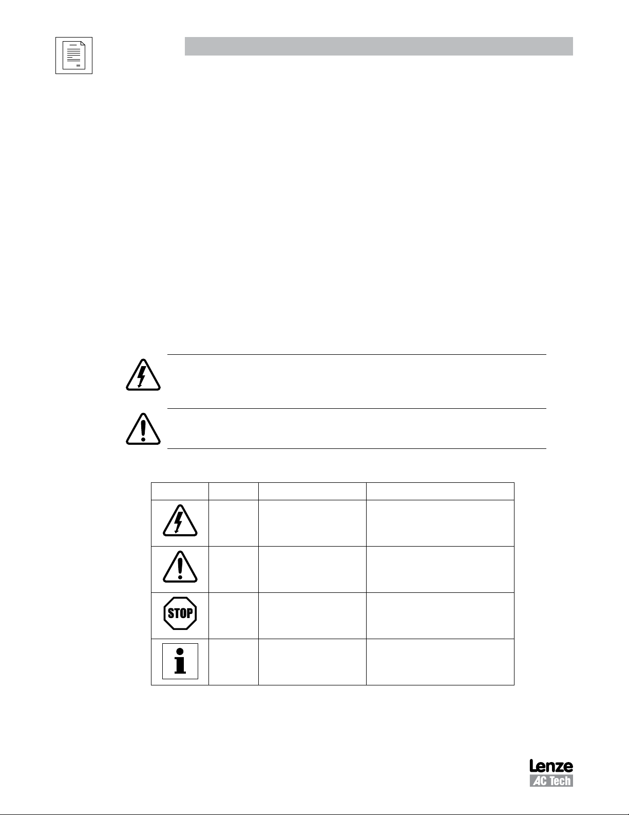
Table 1: Pictographs used in these instructions
Pictograph Signal word Meaning Consequences if ignored
DANGER!
WARNING!
STOP!
NOTE
Warning of Hazardous Electrical
Voltage.
Impending or possible danger
for persons
Possible damage to equipment Damage to drive system or its surroundings
Useful tip: If observed, it will
make using the drive easier
Reference to an imminent danger that may
result in death or serious personal injury if the
corresponding measures are not taken.
Death or injury
1.2 Reference and Links
MC Series Variable Frequency Drives visit: http://www.lenze-actech.com
Modbus-IDA visit: http://www.modbus-IDA.org
RG-MCMOD 2
Page 7
2 Introduction
This document defines the specifics required for Modbus serial communication with a Lenze-AC Tech
standard MC 1000 or MC 3000 Series drive for control, status monitoring, and programming parameters. A
familiarity with normal drive capabilities and operations is assumed. If this is not the case, refer to the MC
Series Installation and Operation manual (M101 or M301, respectively) for more information.
2.1 Modbus Details
A. AC Tech Drives running the Modbus communication protocol use the RTU (Remote Terminal Unit)
transmission mode and are slaves only. Therefore, the device communicating with the drives must be
a Modbus Master. The baud rate is 9600, no parity (two stop bits). The bit sequence is:
Start bit 1 2 3 4 5 6 7 8 Stop bit Stop bit
B. At this time the AC Tech drives do not support the broadcast function of the protocol.
C. IMPORTANT NOTE: Modbus 3X and 4X Registers are numbered starting at 1. However, when
transmitted to a slave over the serial link, the actual address transmitted is one less. This is because
the addresses are numbered starting from 0. AC Tech register numbers are also numbered starting
from 0. Therefore, AC Tech register numbers always correspond exactly with the address transmitted.
As a result, MODBUS REGISTER NUMBERS ARE ALWAYS ONE GREATER THAN AC TECH REGISTER
NUMBERS. WHENEVER THE WORDS “REGISTER #xx” APPEAR, IT SHOULD BE ASSUMED THAT THEY
MEAN “AC TECH REGISTER xx” and the Modbus Register number will be one larger. In some instances
we may show both for clarity. For example: “Register #24 (Modbus Register #25) . . .”
Introduction
DATA
D. The function codes supported by AC Tech drives are:
03 Read Holding Registers (4X references). In general we can read only one register at a time. However,
there are a few limited exceptions.
Exception One:
Register #24 - 29 (Modbus Register #25 - 30) can also be read as a group of 6 words.
Exception Two:
AC Tech uses a method of reading a group of related registers that may not be consecutive within
the drive memory map. When this is done for the registers below, the response from the drive will
be for the number of words requested but will not be with consecutive registers.
Register #100 (Modbus Register #101), Fault history, should be read as a group of 4 words.
Register #101 (Modbus Register #102), Software version, should be read as a group of 4 words.
04 Read Input Registers (3X references). As with function 03, we read one register at a time except
where noted.
06 Preset Single Register (4X references). Write single register.
3 RG-MCMOD
Page 8
Introduction
16 Preset Multiple Registers (4X references). Although the function is for multiple registers, we will
accept only a single register to be written.
Note: Since we do not differentiate between 4X and 3X references, function codes 03 and 04 are
treated identically.
E. Exception codes:
01 - Command rejected, Illegal function
02 - No such register
03 - Data out of range
04 - Wrong data format
06 - Slave device busy. In Keypad Programming mode, cannot write registers.
F. The AC Tech drive will most nearly conform to the Modicon® Micro 84 in capabilities. This may be of
importance when configuring networks for DDE Servers.
G. Modbus® and Modicon® are registered trademarks of Schneider Electric. For more information about
the Modbus Protocol please refer to the Modicon Modbus Protocol Reference Guide. Web resources:
http://www.Modbus-IDA.org and http://www.schneider-electric.com.
2.2 Universal Registers
Lenze-AC Tech manufactures several drive families. Currently the QC, MC, MCH, SC, TC,
Series drives support Modbus based communications. Since each drive family has different parameters
and size ranges, the parameter (register) definitions are in many cases quite different. In order to facilitate
communication in a network with a mix of drive types, certain AC Tech Register locations have been made
universal among AC Tech drives. While their locations are consistent, their contents may vary as defined
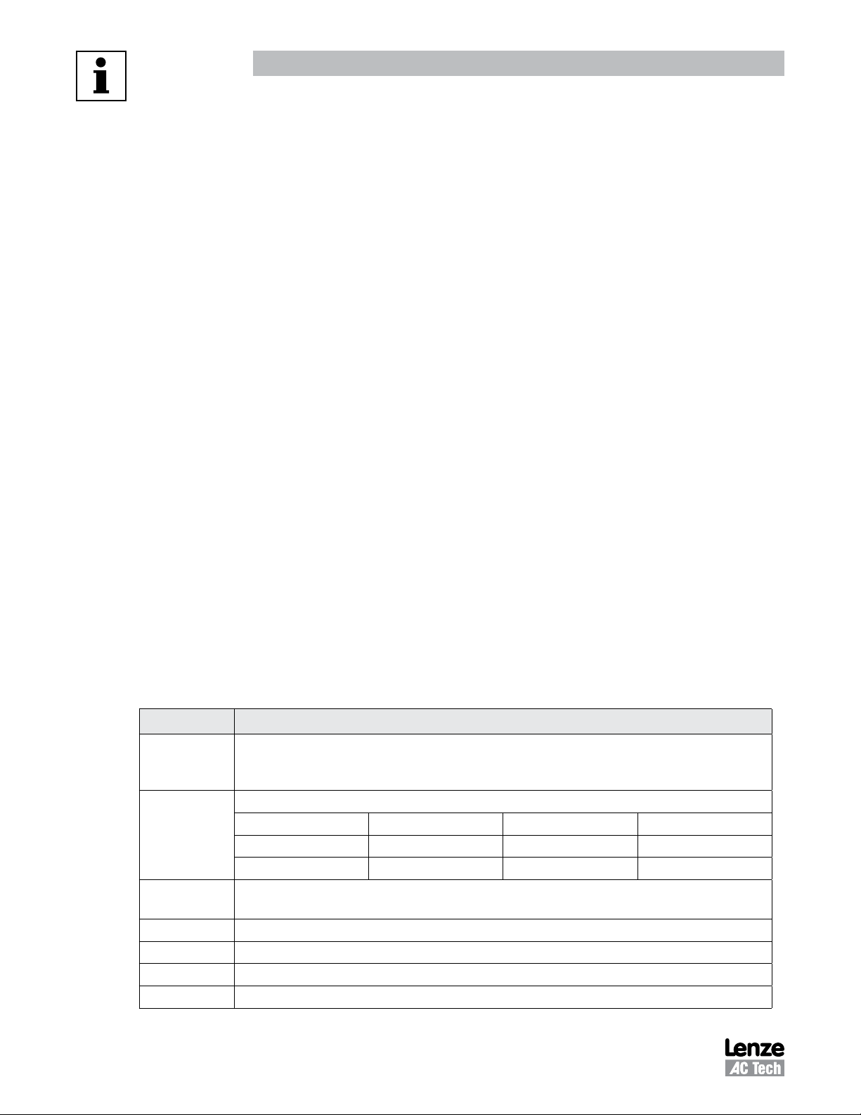
in Table 2.
AC Tech Reg # Function
1 Drive Control (WRITE ONLY). Not all drives will have all control functions but when the function is
available it will be at a defined bit location within Register #1. Drive Family and register Configuration
Number dependent.
19 Drive Family (READ ONLY) This register is CONSISTENT AMONG ALL AC TECH DRIVES:
- 64 -- QC family - 67 -- - 70 -- TC family
- 65 -- MC family - 68 -- MCH family - 71 --
- 66 -- SC family - 69 --
21 Drive Size (READ ONLY). Code to identify Power (HP/KW) and Line Voltage of the drive. Family
dependent. For the MC series drive size refer to section 5.3.
24 Drive Status (READ ONLY). Various operational variables.
48 Unlock Control (WRITE ONLY).
49 Unlock Writing of registers (WRITE ONLY).
50 Parameter Configuration Number (READ ONLY).
Table 2: Contents of Universal Registers
Tmd
smd
family - 72 -- SMV family
family
smd, Tmd
and SMV
RG-MCMOD 4
Page 9
Data & Register Format
3 Data Representation - Internal and External
3.1 Register Format
All registers are 16 bits. The data within these registers can take on the following forms:
• Individual bit commands (16 per register). Example: Register #1 (Modbus Register #2).
• Individual bit flags (16 per register).
• A chain of two 8 bit unsigned integers.
• A 16 bit unsigned integer.
This unsigned integer could represent many different types of data with various scaling rules and
units, which are defined by the DATA TYPE of the register.
3.2 Data Types
Data passed in registers across the Modbus communications link are always in INTERNAL units. The drive
itself may show the information in alternate DISPLAYED units. For Example: drive speeds are always stored
internally as hundredths of a Hz but the drive may display that speed in terms of RPM's using programmed
conversion factors. Table 3 lists examples of the internal units used on the MC series.
The data type "PID" requires further explanation. The internal range of any data of PID type is 0 to 32736.
Many variables can be controlled in a PID system (pressure, temperature, flow, etc.). To simplify drive
calculation, the drive programmer enters the type and range of the controlled variable (actually it is the
range of the feedback device that we are scaling) and this range is mapped to the internal range (0-32736).
If the feedback device measured 0 to 200 PSI, then 0 PSI is 0 internal units, and 200 PSI is 32736 internal
units. To command a setpoint of 100 PSI the LOCAL PID command (Register #41) can be written with the
value 16368 (32736*100/200). Thus to control PID operations using real world units, the Modbus Master
must have knowledge of the range of the feedback device.
3.3 AC Tech Drive Registers
Registers #0 - #50: (Modbus Reg #1 - #51) Reserved for configuration and control
Registers #51 - #260 (Modbus Reg #52 - #261) Reserved for drive's programming mode parameters
Programming Mode Parameters are the parameters accessible from the local keypad on the drive. There is a direct
correspondence between the MC Drive Programming Mode Parameter number and the AC Tech Register number
(and consequently, the Modbus register number):
AC Tech Register # = (MC Programming Parameter #) + 51
Modbus Register # = (MC Programming Parameter #) + 52
Table 3: MC Series Internal Units
Type Unit Example
SPEED .01 Hz 60.00 Hz = 6000
TIME .1 Sec 30.0 Sec = 300
The Table 6 entries are based on MC Drive Software # 213-083 Revision 13 (Parameter Configurations = 188, 189
& 190). If a later revision of software were to change register definitions, drive operation could be seriously affected.
Examine Register #50 (Parameter Configuration Number) for revision. The number displayed at power up on drive
display also identifies it. If it is not 188, 189 or 190, writing to any register on the drive MUST NOT BE ATTEMPTED
unless your Controller has been setup to support the new configuration.
5 RG-MCMOD
Page 10
Drive Setup & Operation
4 MC Drive Setup & Operation
4.1 Serial Address
All AC Tech drives have a Serial Address Parameter that must be programmed prior to attempting to
operate the serial interface (Programming Parameter #58 / AC Tech Register #109).
TIP - Avoid using address 1. Most Modbus devices ship with a default address of 1. As duplicate addressing
on a Modbus network is not allowed, this can lead to conflicts when replacing and commissioning nodes.
To avoid this it is recommended that you do not set the slave address to 1.
4.2 Serial Communications Parameter
All AC Tech drives have a Serial Communications Parameter that governs the operation of the Serial Link.
On MC drives this is #57 SERIAL LINK (register #108). Table 4 lists the selections for MC Parameter 57,
SERIAL LINK.
Table 4: MC Parameter 57 Selections
Setting Description Watchdog Timeout Period
00 DISABLE
01 WITH TIMER 10 sec
02 WITHOUT TIMER
Explanation of Terms:
• DISABLED serial link not operational
• WITH TIMER serial link allows reading & writing of both control & programming parameters.
• WITHOUT TIMER serial link allows reading & writing of both control & programming parameters.
Prior to attempting to communicate with the drive, Serial Communications Parameter must be appropriately
programmed.
4.3 Control Parameter
The Control Parameter on MC drives (Programming Parameter #30 / AC Tech Register #81) determines
how much control a user has over a drive via the serial link. The Control Parameter must be appropriately
programmed for a particular application. Refer to the MC Series Installation and Operation Manual (M101
or M301, respectively) for a detailed explanation on programming the drive parameters.
TIP - For most serial applications, CONTROL is set to LOCAL on the MC1000 and SERIAL on the MC3000.
Refer to Table 5 for Control settings.
Watchdog timer is enabled (refer to section 4.6,
Watchdog timer is disabled (refer to section 4.6,
Watchdog Timer
Watchdog Timer
).
).
RG-MCMOD 6
Page 11
Drive Setup & Operation
MC1000 MC3000
Setting Description Setting Description
00 LOCAL (default) 00 LOCAL (default)
01 REMOTE 01 REMOTE
02 BOTH 02 SERIAL
All control options are subject to the Parameter and Control Locking/Unlocking procedures.
4.4 Unlocking & Locking Controls
Registers #48 and #1 are used in Unlocking and Locking Controls.
• A write to Register #48 (Unlock Controls) with a value of 0 will unlock controls. This enables the writing
of Register #1 – the Drive Control Register.
Table 5: Control (Parameter #30)
03 KEYPAD
04 TB STRIP
05 KEYPAD 2
• If Register #48 (Unlock Controls) is written with a value that is the Drive’s Programming Password, then
in addition to Register #1(Drive Control), writing to all other writeable registers is enabled (e.g.: register
#52 -- Preset Speed #1). The factory default password for MC series drives is 19.
• Once Register #48 (Unlock Controls) has been written, Controls are unlocked until the Lock Security
flag (Bit 1 of Register#1) has been set or until a Watchdog Timeout occurs.
• Writing to Register #1 (Drive Control) with bit 1 set will Lock both Controls and Parameters (prevents
writing to any register).
• The serial drive control can only be unlocked when the drive is not in programming mode.
• When LOCK is asserted, the drive drops out of SERIAL control and reverts back to the previous source
of control.
• Even though drive might be locked, and thus parameters and control cannot be written, parameters
and status can always be read. Refer to section 4.7,
Monitoring Only Operation
4.5 Unlocking & Locking Programming Parameters only
Registers #49 and #1 are used in Unlocking and Locking Programming Parameters.
• Writing to any writeable register other than #1 can be enabled by writing the Drive’s Programming
Password to Register #49 (Unlock Parameters). This would be done when Drive Control (start, forward/
reverse, keypad speed control, etc.) is not required.
.
• The Factory Default password is 19.
• Once Register #49 (Unlock Parameters) has been written, the writing of parameter registers is enabled
until Bit 1 of Register #1 has been set.
7 RG-MCMOD
Page 12

4.6 Watchdog Timer
All AC Tech drives are equipped with a Serial Link “Watchdog Timer”. If the Modbus Master wishes to
control the drive (start, stop, forward, reverse, etc.) it must first “Unlock Controls” (refer to section 5.10).
If the Watchdog Timer is enabled and controls have been unlocked, the Master MUST PERIODICALLY
COMMUNICATE with the drive or the timer will timeout. The timeout period is fixed at 10 seconds. It is
recommended that the drive be polled at least once every 5 seconds. Register #24 can be used for this
purpose.
The action of a Watchdog timeout depends on the setting of the CONTROL parameter. If the CONTROL
parameter is set for:
− LOCAL : the drive will stop when a serial timeout occurs.
− KEYPAD 2 (LOCAL contol without the need for TB-1 to run): the drive will stop when a serial timeout
occurs.
− REMOTE: serial timeout will not work since the drive cannot be unlocked in REMOTE mode.
− MC1000/3000 drives STOP when a serial timeout occurs. There is no fault for this. Any time CONTROL
is changed from LOCAL to REMOTE the drive STOPS immediately.
Drive Setup & Operation
The Watchdog Timer does not operate unless Controls have been UNLOCKED via Register #48, or Parameter
writing has been unlocked via Register #49. In the case of unlocking parameters only, the watchdog timer
will disable write permissions but will otherwise continue with normal operation.
Watchdog Timer Controls
− For some applications, it is inappropriate to shut down the drive because of a Watchdog Timeout.
Therefore, we have provided a means of disabling the Watchdog using Programming Parameter
#57 (SERIAL LINK):
Programming Parameter #57 controls both the enabling of the serial link and the Watchdog. By
setting Parameter #57 to WITH TIMER enables the serial link WITH the Watchdog. Conversely,
setting Parameter #57 to WITHOUT TIMER enables the serial link WITHOUT the Watchdog.
− A Watchdog failure can be recognized by reading the drive status (AC Tech Registers #24 – 29) and
looking at the control mode. If it has reverted from SERIAL to LOCAL without the Modbus Master
commanding it via Register #1 bit 1 (LOCK) then a watchdog failure has occurred. Serial Control
can be reestablished by writing another unlock message to Register #48.
− If the Watchdog Timer has been disabled, the Unlock Control Register #48 or Unlock Writing
Register #49 must still be asserted in order to write to Register #1 (Drive Control) or to any of
the programming parameters (in case of unlocking writing). However, there are no longer any
constraints on how often the Master must communicate with the drive.
RG-MCMOD 8
Page 13

Drive Setup & Operation
4.7 Monitoring Only Operation
1. Power up drive with serial enabled.
2. Simply read AC Tech Register #24 (Modbus Register #25) or any other readable register.
3. No unlocking or watchdog issues apply for monitoring.
4.8 Normal Control Operation Sequence
1. Power up drive with serial enabled.
2. Unlock control by writing a zero to Register #48.
3. Control drive operation via various commands to Register #1 (Start, Stop, Reverse direction, etc.).
4. If the Watchdog Timer is enabled, keep it from timing out by repeated reads of drive status (Register
#24 – 6 registers) performed at reasonable intervals (typically less than 5 seconds between reads
because the Watchdog typically faults at 10 seconds).
5. Lock Control when drive operations are complete by writing a 2 to Register #1 (assert bit 1 of Register
#1).
6. Drive is now returned to LOCAL mode (control from the drive keypad).
4.9 Start/Stop, Speed Control and Parameter Change Operation
The typical sequence for a Start/Stop, Speed Control or Parameter Change operation is listed herein.
1. Power up drive with serial enabled.
2. Unlock Controls and Parameters by writing the current programming password (default 19) to Register
#48.
3. Put drive in MANUAL mode so that it responds to speed commands from the Keypad Speed Command
register. This is done by sending 0200 hex to Register #1 (bit 9 asserted).
4. Control Drive Operation via various commands to Register #1 (Start, Stop, Reverse direction, etc.).
5. Control Drive Speed by writing the Speed Commands to Register #40 (Keypad Speed Command).
6. Change the programming parameters (e.g., change the acceleration rate by writing new acceleration
rate to register #59)
7. If the Watchdog Timer is enabled, keep it from timing out by insuring that repeated reads of any of the
registers are performed at reasonable intervals (typically less than 5 seconds between reads because
the Watchdog typically faults at 10 seconds). Note: It is suggested that the drive status register (#24)
be used for this function.
8. Lock Controls and Parameters when drive operations are complete by writing a 2 to Register #1 (assert
bit 1 of Register #1).
9. Drive is now returned to the control method programmed in Parameter 30, CONTROL (i.e., local control
from the drive keypad).
9 RG-MCMOD
Page 14

Drive Control & Communication
5 MC Drive Control Registers
Table 6 describes the MC Drive Control Registers in ascending order of AC Tech Register #. The HEX
representation is given in parenthesis next to the AC Tech Register # in the left-most column.
Table 6: MC Drive Control Registers
REGISTER NAME
ACT# (HEX
representation)
1 (01) Drive Control
19 (13) Drive Family
21 (15) Drive Size
Drive Status
24 (18)
24 (18) Command Speed
25 (19) Actual Speed
26 (1A)
27 (1B)
28 (1C)
29 (1D)
30 (1E) Motor Voltage
36 (24) Total Run Time Hours
37 (25) Total Run Time Minutes
38 (26)
39 (27)
40 (28) Keypad Speed Command
(6 register read)
(reg. #24 to 29)
Load (DH) /
Status (DL)
Actual Direction (DH) /
Control Mode (DL)
Speed Source (DH) /
Speed Reference (DL)
Fault (DH) /
Commanded Direction (DL)
PID Setpoint
(MC1000 w/PID, MC3000)
PID Feedback
(MC1000 w/PID, MC3000)
R/W/RS
MESSAGE MIN MAX UNITS
W SA 06 00 01 DH DL CRCH CRCL
RS SA 06 00 01 DH DL CRCH CRCL
R SA 03 00 13 00 01 CRCH CRCL
RS SA 03 02 00 41 CRCH CRCL
R SA 03 00 15 00 01 CRCH CRCL
RS SA 03 02 00 00 CRCH CRCL
R SA 03 00 18 00 06 CRCH CRCL
RS SA 03 0C D1H D1L D2H D2L
D3H D3L D4H D4L
D5H D5L D6H D6L
CRCH CRCL
R SA 03 00 18 00 01 CRCH CRCL
RS SA 03 02 DH DL CRCH CRCL
R SA 03 00 19 00 01 CRCH CRCL
RS SA 03 02 DH DL CRCH CRCL
R SA 03 00 1A 00 01 CRCH CRCL
RS SA 03 02 DH DL CRCH CRCL
R SA 03 00 1B 00 01 CRCH CRCL
RS SA 03 02 DH DL CRCH CRCL
R SA 03 00 1C 00 01 CRCH CRCL
RS SA 03 02 DH DL CRCH CRCL
R SA 03 00 1D 00 01 CRCH CRCL
RS SA 03 02 DH DL CRCH CRCL
R SA 03 00 1E 00 01 CRCH CRCL
RS SA 03 02 DH DL CRCH CRCL
R SA 03 00 24 00 01 CRCH CRCL
RS SA 03 02 DH DL CRCH CRCL
R SA 03 00 25 00 01 CRCH CRCL
RS SA 03 02 DH DL CRCH CRCL
R SA 03 00 26 00 01 CRCH CRCL
RS SA 03 02 DH DL CRCH CRCL
R SA 03 00 27 00 01 CRCH CRCL
RS SA 03 02 DH DL CRCH CRCL
R SA 03 00 28 00 01 CRCH CRCL
RS SA 03 02 DH DL CRCH CRCL
W SA 06 00 28 DH DL CRCH CRCL
RS SA 06 00 28 DH DL CRCH CRCL
[NOTE]
Section
Refer to Section 5.2 [1]
Refer to Section 5.2 [2]
Refer to Section 5.3
Refer to Section 5.4
0 2400 0.1 Hz
0 2400 0.1 Hz
Refer to Section 5.4.1/2
Refer to Section 5.4.3/4
Refer to Section 5.4.5/6
Refer to Section 5.4.7/8
0 999 V 5.5
Refer to Section 5.7
Refer to Section 5.7
Refer to Section 5.8
Refer to Section 5.8
0 65000 0.01 Hz 5.6
or
[3a]
[3b]
[3c]
RG-MCMOD 10
Page 15

Drive Control & Communication
REGISTER NAME
ACT# (HEX
representation)
41 (29)
48 (30) Unlock Commands
49 (31) Unlock Parameters
50 (32) Register Version
Local PID Command
(MC1000 w/PID, MC3000)
5.1 Abbreviations
Table 7 lists the abbreviations used in Table 6 MCH Drive Control Registers:
R/W/RS
R SA 03 00 29 00 01 CRCH CRCL
RS SA 03 02 DH DL CRCH CRCL
W SA 06 00 29 DH DL CRCH CRCL
RS SA 06 00 29 DH DL CRCH CRCL
W SA 06 00 30 DH DL CRCH CRCL
RS SA 06 00 30 DH DL CRCH CRCL
W SA 06 00 31 DH DL CRCH CRCL
RS SA 06 00 31 DH DL CRCH CRCL
R SA 03 00 32 00 01 CRCH CRCL
RS SA 03 02 DH DL CRCH CRCL
MESSAGE MIN MAX UNITS
Refer to Section 5.8
0 9999 None 5.10
0 9999 None 5.11
0 65535 None 5.12
Table 7: Abbreviations
Abbreviation Description
R Read
W Write
RS Response
SA Slave Address (typically 01 through F7 hex)
CRCH CRC High byte
CRCL CRC Low byte
DH Data High byte
DL Data Low byte
ACT# AC Tech Register # (Modbus Register numbers are 1 larger)
[NOTE]
or
Section
11 RG-MCMOD
Page 16

Drive Control & Communication
5.2 Drive Control - Register #1
Table 8 illustrates the Data format of Register #1, Drive Control.
Table 8: Drive Control - Register #1
Bit Command
0 UPDATE BUFFERS
1 LOCK SECURITY
2 STOP DRIVE
3 START DRIVE
4 UNUSED
5 UNUSED
Data Low Byte
6 SET REVERSE
7 SET FORWARD
8 AUTO MODE
9 MANUAL MODE
10 UNUSED
11 UNUSED
12 UNUSED
13 UNUSED
Data High Byte
14 UNUSED
15 UNUSED
The appropriate bit is set to 1. For example, to stop the drive bit two is set (send 0004H). To start the drive
send 0008H. Setting update buffers bit, enables to start the drive using downloaded data. Locking security
disables the serial drive control, the communications watchdog timer and prevents any further writing to
control or parameter registers.
NOTE 1 - Drive Control
• During each write to Register #1 only one bit should be set in the drive control word.
• If more than 1 bit is set, the drive responds to stop bit only.
• If stop bit is not set, but more than 1 bit is set, drive responds with exception 04.
NOTE 2 - Drive Family
• The QC and DL Series drives return 64 (40H)
• The MC Series drives return 65 (41H)
• The SC Series drives return 66 (42H)
• The MCH Series drives return 68 (44H)
• The
smd
Series drives return 69 (45H)
• The TC Series drives return 70 (46H)
• The
Tmd
Series drives return 71 (47H)
• The SMV Series drives return 72 (48H)
RG-MCMOD 12
Page 17

Drive Control & Communication
5.3 Drive Size - Register #21
Table 9 lists the MC1000 and MC3000 Series drives. Register 21 will contain the value in the "Size"
column.
Size HP Voltage Size HP Voltage
Table 9: Drive Size - Register #21
0 0.25 120 29 2 590
1 0.25 240 30 3 590
2 0.5 240 31 5 590
3 1 240 32 7.5 590
4 1.5 240 33 10 590
5 2 240 34 15 590
6 3 240 35 20 590
7 5 240 36 25 590
8 7.5 240 37 30 590
9 10 240 38 40 590
10 15 240 39 50 590
11 20 240 40 60 590
12 25 240 41 75 590
13 50 480 42 100 590
14 60 480 43 125 590
15 1 480 44 150 590
16 1.5 480 45 200 590
17 2 480 46 75 480
18 3 480 47 100 480
19 5 480 48 125 480
20 7.5 480 49 150 480
21 10 480 50 200 480
22 15 480 51 30 240
23 20 480 52 40 240
24 25 480 53 50 240
25 30 480 54 60 240
26 40 480 55 75 240
27 1 590 56 100 240
28 1.5 590 57 N/A N/A
13 RG-MCMOD
Page 18

Drive Control & Communication
5.4 Drive Status - Registers #24-29
5.4.1 Reading Register #24
When reading register #24, the number of wordscan either be 1 or 6. This is an exception to the rule of
being able to read only one register at a time. If 6 words are requested at register #24, the following will
be returned:
Table 10: 6 Register read at #24
Parameter Data Byte
Command Speed D1H D1L
Actual Speed D2H D2L
Load D3H
Operation Status D3L
Rotational Direction D4H
Control Mode D4L
Speed Command Source D5H
Speed Reference D5L
Present Fault D6H
Command Rotation D6L
NOTE 3a - Command Speed (Bytes D1H and D1L or Register #24)
• In hundredths of a Hz
• Most significant byte is first, followed by Least significant
• Example: 02 01 in hex converts to 5.13Hz in decimal.
NOTE 3b - Actual Speed (Bytes D2H and D2L or Register #25)
• In hundredths of a Hz
• Most significant byte is first, followed by Least significant
NOTE 3c - Load (Bytes D3H or Register #26 DH)
• In percent of full load
• Example: 64 (one byte in hex) ==> 100 in decimal ==> 100% (drive load).
RG-MCMOD 14
Page 19

Drive Control & Communication
5.4.2 Operational Status - Registers #24 & 26
Table 11 lists the Operational Status (byte D3L)
Table 11: Operational Status - Register #26
Setting Parameter
0 FAULT LOCKOUT
1 FAULT
2 START PENDING
3 STOP
4 DC BRAKE
5 RUN AT 0Hz
6 RUN
7 ACCEL
8 DECEL
9 CURRENT LIMIT
10 DECEL OVERRIDE
11 LOWER TRANSISTORS SWITCHING ON
12 SLEEP
5.4.3 Actual Rotational Direction - Registers #24 & 27
Table 12 lists the Actual Rotational Direction (Register #24 byte D4H or Register #27 DH).
Table 12: Actual Rotational Direction
Setting Direction
0 FORWARD
1 REVERSE
5.4.4 Control Mode - Registers #24 & 27
Table 13 lists the Control Mode (Register #24 byte D4L or Register #27 DL).
Table 13: Control Mode
Setting Control Operation
0 LOCAL Start/Stop operation controlled from drive's keypad
1 REMOTE Start/Stop operation controlled from the drive's terminal strip
2 SERIAL Start/Stop operation controlled via serial link
15 RG-MCMOD
Page 20

Drive Control & Communication
5.4.5 Speed Command Source - Registers #24 & 28
Table 14 lists the Speed Command Source (Register #24 byte D5H or Register #28 DH).
Table 14: Speed Command Source
Setting Source
0 KEYPAD
1 0 – 10VDC
2 4 – 20mA
3 PRESET 1
4 PRESET 2
5 PRESET 3
6 PRESET 4
7 MOP
8 RESERVED
9 KEYPAD SPEED (PID enabled)
10 PID KEYPAD SETPOINT
11 0-10 VDC PID SETPOINT
12 4-20mA PID SETPOINT
5.4.6 Speed Reference - Registers #24 & 28
Table 15 lists the Speed Reference Control (Register #24 byte D5L or Register #28 DL).
Table 15: Speed Reference Control
Setting Control
0 AUTO
1 MANUAL
RG-MCMOD 16
Page 21

Drive Control & Communication
5.4.7 Present Fault - Registers #24 & 29
Table 16 lists the Present Fault (Register #24 byte D6H or Register #29 DH)
Setting Fault Display
0 NO FAULT
1 OUTPUT (TRANSISTOR) FAULT OUTPUT
2 Reserved
3 HIGH DC BUS VOLTAGE HI VOLTS
4 HIGH DRIVE TEMPERATURE HI TEMP
5 THERMAL OVERLOAD OVERLOAD
6 Reserved
7 LOW DC BUS VOLTAGE LO VOLTS
8 Reserved
9 DC BRAKE ERROR DB ERROR
10 FOLLOWER LOSS FLWR/SER
11 DYNAMIC BRAKE OVERLOAD DB ERROR
12 POWER SAG PWR SAG
13 CONTROL FAULT CONTROL
14 LANGUAGE FAULT LANGUAGE
15 EXTERNAL FAULT EXTERNAL
16 INTERNAL 16 INTERNAL
17 POWER TRANSIENT PWR TRAN
18 INTERNAL ERROR #18 INTERN #18
19 INTERNAL ERROR #19 INTERN #19
20 INTERNAL ERROR #20 INTERN #20
21 INTERNAL ERROR #21 INTERN #21
22 INTERNAL ERROR #22 INTERN #22
23 INTERNAL ERROR #23 INTERN #23
Table 16: Present Fault
5.4.8 Commanded Rotational Direction - Registers #24 & 29
Table 17 lists the Commanded Rotational Direction (Register #24 byte D6L or Register #29 DL)
Table 17: Commanded Rotational Direction
Setting Direction
0 FORWARD
1 REVERSE
5.5 Motor Volts - Register #30
Output Voltage to the motor expressed in volts. This is the effective output voltage to the motor. It is not the
same as the incoming voltage to the drive from the line.
17 RG-MCMOD
Page 22

Drive Control & Communication
5.6 Keypad Speed - Register #40
This register enables the user to set the keypad speed to desired value.
• Range is 0 - 65000 in hundredths of a Hz
• Most significant byte is first, followed by Least significant
• CONTROL OF THE DRIVE SPEED VIA THE SERIAL LINK IS NORMALLY DONE USING THIS PARAMETER.
This register can be written only after enabling serial drive control.
5.7 Total Run Time - Registers #36 & 37 (MC3000 only)
Register #36 - Total Run TIme in Hours Example: A value of 20 in decimal equals 20 Hours
Register #37 - Total Run TIme in Minutes Example: A value of 42 in decimal equals 42 Minutes
5.8 PID Commands - Registers #38, 39, 41 & 43
Registers #38 (PID Setpoint Command), #39 (PID Feedback Value), #41 (Local PID Setpoint Command) and
#43 (Serial PID Command) are all in drive internal units with a range of 0 to 32736. The real world parameter
being controlled is mapped into this internal range based on the feedback device for the parameter being
measured and controlled.
For Example, if the device measures temperature in °C with a range of 10°C to +110°C, then 10°C maps
to 0 in internal units and 110 maps to 32736. A setpoint of 30 °C for the Local PID Setpoint (Register #41)
would be written with a value of 6547 (1993 hex). (32736 * {30 – 10} / {110 – 10}).
5.10 Unlock Commands - Register #48
Register #48 (Unlock Commands) unlocks commands by using 0000 for the password. If the correct
Programming mode password is entered then the appropriate programming parameters can also be
accessed (refer to the full parameter protocol specification if access to programming parameters is
required). Enabling commands also activates the drive Watchdog timer if programming parameter #15
(Serial) is set to W/TIMER (it uses a fixed 10 seconds timeout). If the drive sees no activity within the update
time period it will stop the drive. Whenever a communications session (where #48 or #49was activated) is
to be ended, register #1 bit 1 (Lock Security) must be asserted. This disables the watchdog and prevents
further accesses to registers. Note: Terminal TB1 must be closed in order to unlock serial control.
5.11 Unlock Parameters - Register #49
Register #49 (Unlock Parameters) unlocks programming parameters for writing when the proper
Programming Password is entered. Whenever a parameter writing session (where #49 was activated) is
to be ended, register #1 bit 1 (Lock Security) must be asserted. This disables the watchdog and prevents
further write access to Parameter Registers.
RG-MCMOD 18
Page 23

Drive Control & Communication
5.12 Register Version
Register Version is the number to identify if current version of software has any register changes relative
to previous versions: a register has been added or deleted, a register’s min/max limits have changed, a
register’s function has been changed, or a register’s default value has been changed. Generally it is the
programming parameters that are changed. Typically the Control Registers (AC TECH Register #1 through
#50) are quite stable.
19 RG-MCMOD
Page 24

Drive Control & Communication
6 MC Programming Parameters
6.1 Format
NOTE - Attention
Parameter list presented in Section 6.2 is valid only for MC Software revision 213-083.
For revisions, refer to appropriate MC1000 (M101) or MC3000 (M301) Manual.
Abbreviations:
SA (1byte) drive address (1-247)
RA (1byte) register address
CRCH (1 byte) Cyclic Redundancy Check High
CRCL (1 byte) Cyclic Redundancy Check L
READING:
Message structure for reading 1 word: (most of parameters)
Request: SA 03 00 RA 00 01 CRCH CRCL
Response: SA 03 02 DH DL CRCH CRCL
Message structure for reading 4 word: (Reg. #100 Fault history and #101 Software Version)
Request: SA 03 00 RA 00 04 CRCH CRCL
Response: SA 03 08 D1H D1L D2H D2L D3H D3L D4H D4L CRCH CRCL
WRITING:
Message structure for writing 1 word: (all parameters)
Request: SA 06 00 RA DH DL CRCH CRCL
Response: SA 06 00 RA DH DL CRCH CRCL
LEGEND for Parameter List
1st Column: AC Tech Register # MC Register # followed by Hex value in parenthesis: 51 (33H)
1
2nd Column: Parameter
= Drive's programming parameter number
2
= MC1000 without PID (SW version 213-083, revision 13 or older)
3
= MC1000 with PID
4
= MC3000
4th Column: Range of Adjustment The Modbus values are whole numbers. One decimal place is
assumed. A superscript 5 denotes parameter where two decimal
places are assumed.
For example, to program a value of 28.20 Hz, the user can program
28.20 into the MC drive and the drive will display 28.20 but for
Modbus communications, the user must input 2820. The one
decimal place is assumed. If the user wanted a value of 282 Hz,
then for Modbus communications he would have to input 28200.
5th Column: Default Value
5
= Two decimal places assumed (hundredths)
RG-MCMOD 20
Page 25

Drive Control & Communication
6.2 Parameter List
AC Tech
Register
1
Parameter Name Range of Adjustment
Modbus value (decimal value)
Factory Default
Number
(hexadecimal
representation)
51 (33) 0 LINE VOLTS 00 - High
Parameter
02 - Auto
01 - Low
02 - Auto
52 (34) 1 SPEED #1 Min. Freq - Max. Freq (0.00 - 120.00 Hz) 2000 (20.00 Hz)
53 (35) 2 SPEED #2 Min. Freq - Max. Freq 2000 (20.00 Hz)
54 (36) 3 SPEED #3 Min. Freq - Max. Freq 2000 (20.00 Hz)
55 (37) 4 SPEED #4 Min. Freq - Max. Freq 2000 (20.00 Hz)
56 (38) 5 SKIP #1 MC1: 0 - 65000 (.00 - 650.00 Hz)
0 (.00 Hz)
5
MC3: 0 - Max Freq (.00 Hz - Max. Freq)
57 (39) 6 SKIP #2 MC1: 0 - 65000 (.00 - 650.00 Hz);
0 (.00 Hz)
5
MC3: .0 - Max Freq (00 Hz - Max. Freq)
58 (3A) 7 BAND WID 0 - 1000 (.00 - 10.00 Hz) 100 (1.00 Hz)
5
59 (3B) 8 ACCEL Refer to Note 4 300 (30.0 sec)
60 (3C) 9 DECEL Refer to Note 5 300 (30.0 sec)
61 (3D) 10 MIN FREQ 0 - Max Frequency (0.00 - 120.00 Hz) 50 (.50 Hz)
5
62 (3E) 11 MAX FREQ Min Frequency - 12000 (120.00 Hz) Note 6 6000 (60.00 Hz)
63 (3F) 12 DC BRAKE Refer to Note 7 0 (.0 VDC)
64 (40) 13 DC TIME 0 - 9999 (.0 - 999.9 sec) 0 (.0 sec)
65 (41) 14 DYN BRAKE 00 - Off
00 - Off
01 - On
67 (43) 16 CURRENT 25 - 180 (25 - 180%), Refer to Note 8 180 (180%)
68 (44) 17 MOTOR OL 25 - 100 (25 - 100%) 100 (100%)
69 (45) 18 BASE 2000 - 36000 (20.00 - 360.0 Hz) 6000 (60.00 Hz)
70 (46) 19 FX BOOST 0 - 300 (0.0 - 30.0%) Refer to Note 9
71 (47) 20
72 (48) 21
73 (49) 22 TORQUE 00 - Contant
2,3
AC BOOST 0 - 200 (0.0 - 20.0%) 0 (.0%)
2,3
SLIP CMP 0 - 50 (0.0 - 5.0%) 0 (.0%)
00 - Constant
01 - Variable
02 - CT/NOCMP
74 (4A) 23 CARRIER 00 - 2.5 kHz
00 - 2.5 kHz
01 - 6 kHz
02 - 8 kHz
03 - 10 kHz
04 - 12 kHz
05 - 14 kHz
5
5
5
5
5
5
1 = Drive's programming parameter number; 2 = MC1000 without PID (SW ver 213-083, rev 13 or older); 3 = MC1000 with PID; 4 = MC3000; 5 = Hundredths place
21 RG-MCMOD
Page 26

Drive Control & Communication
AC Tech
Register
1
Parameter Name Range of Adjustment
Modbus value (decimal value)
Number
(hexadecimal
representation)
76 (4C) 25
Parameter
2,3
START 00 - Normal
01 - Power-Up
02 - Auto Re03 - Re-Brake
4
76 (4C) 25
START 00 - Normal
01 - Power-Up
02 - Auto 1
03 - Auto 2
04 - Auto 3
77 (4D) 26 STOP 00 - Ramp
01 - Coast
2,3
78 (4E) 27
ROTATION 00 - Forward
01 - Reverse
02 - FWD & REV
03 - FWD@LOC
2,3
79 (4F) 28
AUTO/MAN 00 - Both
01 - Auto
02 - Manual
79 (4F) 28
4
AUTO/MAN 00 - A/M LOC
01 - Auto
02 - Manual
03 - A/M SPD
2,3
80 (50) 29
MANUAL 00 - Keypad
01 - 0-10 VDC
81 (51) 30
2,3
CONTROL 00 - Local
01 - Remote
02 - Both
4
81 (51) 30
CONTROL 00 - Local
01 - Remote
02 - Serial
03 - Keypad
04 - TB Strip
05 - Keypad
2
82 (52) 31
HZ UNITS 00 - Hertz
01 - RPM
02 - % Hz
03 - /SEC
04 - /MIN
05 - /HR
06 - GPH
07 - None
Factory Default
00 - Normal
00 - Normal
01 - Coast
00 - Forward
00 - Both
00 - A/M LOC
00 - Keypad
00 - Local
00 - Local
00 - Hertz
1 = Drive's programming parameter number; 2 = MC1000 without PID (SW ver 213-083, rev 13 or older); 3 = MC1000 with PID; 4 = MC3000
RG-MCMOD 22
Page 27

Drive Control & Communication
AC Tech
Register
1
Parameter Name Range of Adjustment
Modbus value (decimal value)
Factory Default
Number
(hexadecimal
representation)
82 (52) 31
83 (53) 32 HZ MULT 10 - 65000 (.10 - 650.00) 100 (1.00)
84 (54) 33 SPEED DP 00 - XXXXX
Parameter
3,4
UNITS
Speed:
00 - Hertz
01 - RPM
02 - % Hz
03 - /SEC
04 - /MIN
05 - /HR
06 - GPH
07 - None
PID:
08 - %
09 - PSI
10 - FPM
11 - CFM
12 - GPM
13 - IN
14 - FT
00 - Hertz
15 - /SEC
16 - /MIN
17 - /HR
18 - F
19 - C
20 - MPM
21 - GPH
5
00 - XXXXX
01 - XXX.X
02 - XX.XX
03 - X.XXX
04 - .XXXX
84 (54) 33 UNITS DP 00 - XXXXX
00 - XXXXX
01 - XXX.X
02 - XX.XX
03 - X.XXX
04 - .XXXX
85 (55) 34 LOAD MLT 95 - 139 (95 - 139%) 100 (100%)
86 (56) 35 CONTRAST 00 - Low
02 - High
01 - Medium
02 - High
87 (57) 36 SLEEP TH 0 - 36000 (.00 - 360.00 Hz) 0 (0.00)
88 (58) 37 SLEEP DL 0 - 3000 (.00 - 30.00 Hz) 3000 (30.00)
89 (59) 38
3,4
SLEEP BW 0 - PID Feedback Range 0 (0.0)
90 (5A) 39 TB5 MIN 0 - 36000 (.00 - 360.00 Hz) 0 (.00 Hz)
91 (5B) 40 TB5 MAX 0 - 36000 (.00 - 360.00 Hz) 0 (.00 Hz)
92 (5C) 41 AIN FLTR 1 - 1000 (0.01 - 10.00 sec) 2 (0.02 sec)
93 (5D) 42 TB10A OUT 00 - None
00 - None
5
5
5
5
5
01 - 0 - 10 VDC
02 - 2 - 10 VDC
94 (5E) 43 @TB10A 0 - 36000 (0.00 - 360.00 Hz) 6000 (60.00 Hz)
95 (5F) 44 TB10B OUT 00 - None
00 - None
01 - 0 - 10 VDC
02 - 2 - 10 VDC
96 (60) 45 @TB10B 10 - 200 (10 - 200%) 125 (125%)
5
1 = Drive's programming parameter number; 2 = MC1000 without PID (SW ver 213-083, rev 13 or older); 3 = MC1000 with PID; 4 = MC3000; 5 = Hundredths place
23 RG-MCMOD
Page 28

Drive Control & Communication
AC Tech
Register
1
Parameter Name Range of Adjustment
Modbus value (decimal value)
Factory Default
Number
(hexadecimal
representation)
98 (62) 47 TB13A 00 - None
Parameter
00 - None
01 - 0 - 10 VDC
02 - 4 - 20 mA
03 - Speed #1
04 - Loc Sel
05 - Dec Freq
99 (63) 48
TB13B 00 - None
00 - None
2,3
01 - 0 - 10 VDC
02 - 4 - 20 mA
03 - Speed #2
04 - Inc Freq
05 - Jog Fwd
06 - Jog Rev
99 (63) 48
TB13B 00 - None
00 - None
4
01 - 0 - 10 VDC
02 - 4 - 20 mA
03 - Speed #2
04 - Inc Freq
100 (64) 49
2,3
TB13C 00 - None
00 - None
01 - 0 - 10 VDC
02 - 4 - 20 mA
03 - Speed #3
04 - Loc Sel
05 - Run Rev
06 - Strt Rev
100 (64) 49
TB13C 00 - None
00 - None
4
01 - 0 - 10 VDC
02 - 4 - 20 mA
03 - Speed #3
04 - Loc Sel
05 - Strt Rev
101 (65) 50 TB13D 00 - EXT Fault
00 - EXT Fault
01 - EXT /Fault
02 - EXT Clear
103 (67)
104 (68)
105 (69)
52
53
54
2
2
TB14OUT
TB15OUT
RELAY
00 - None
01 - Run
02 - Fault
00 - None
2
03 - /Fault
04 - Lock
05 - @ Speed
06 - Above #3
07 - I Limit
08 - Auto/Man
09 - Follower Present
10 - Reverse
1 = Drive's programming parameter number; 2 = MC1000 without PID (SW ver 213-083, rev 13 or older); 3 = MC1000 with PID; 4 = MC3000
RG-MCMOD 24
Page 29

Drive Control & Communication
AC Tech
Register
1
Parameter Name Range of Adjustment
Modbus value (decimal value)
Factory Default
Number
(hexadecimal
representation)
103 (67)
104 (68)
105 (69)
52
53
54
3,4
3,4
3,4
Parameter
TB14OUT
TB15OUT
RELAY
00 - None
01 - Run
02 - Fault
03 - /Fault
04 - Lock
05 - @ Speed
06 - Above #3
07 - I Limit
08 - Auto/Man
10 - Min/Max
11 - /Min/Max
12 - Min Alarm
13 - /Min Alarm
14 - Max Alarm
15 - /Max Alarm
16 - Reverse
17 - Sleep
18 - SPD = 0Hz
00 - None
09 - Follower Present
106 (6A) 55
3,4
TB5B LOSS 00 - Fault
00 - Fault
01 - SP#4
02 - None
108 (6C) 57 SERIAL 00 - Disable
00 - Disable
01 - w/ Timer
02 - w/o Timer
109 (6D) 58 ADDRESS 1 - 247 30
112 (70) 61 PASSWORD 0000 - 9999 0019
114 (72) 63 SOFTWARE (View Only) (N/A)
115 (73) 64 MONITOR 00 - OFF
01 - ON
01 - ON
116 (74) 65 PROGRAM 00 - Maintain
01 - Reset 60
01 - Reset 60
02 - Reset 50
Refer to Note 10
117 (75) 66 HISTORY 00 - Maintain
00 - Maintain
01 - Clear
121 (79) 70
PID MODE 00 - Off
00 - Off
3,4
01 - Normal
02 - Reverse
125 (7D) 74
PID FB 00 - TB-5A
00 - TB-5A
3,4
01 - TB-5B
3,4
126 (7E) 75
127 (7F) 76
129 (81) 78
130 (82) 79
131 (83) 80
132 (84) 81
133 (85) 82
149 (95) 69
FB @ MIN 0 - 65000 0 (0.0%)
3,4
FB @ MAX 0 - 65000 65000 (100%)
3,4
I GAIN 0 - 100 (0.0 - 10.0 sec) 0 (0.0 sec)
3,4
D GAIN 0 - 100 (0.0 - 10.0 sec) 0 (0.0 sec)
3,4
PID ACC 0 - 1000 (0.0 - 100.0 sec) 300 (30.0 sec)
3,4
MIN ALRM FB @ MIN - FB @ MAX 0.0%
3,4
MAX ALRM FB @ MIN - FB @ MAX 0.0%
2
LANGUAGE Refer to Note 11 English
98
2
150 (96) 70
99
FAULT HISTORY (View Only) (N/A)
3,4
1 = Drive's programming parameter number; 2 = MC1000 without PID (SW ver 213-083, rev 13 or older); 3 = MC1000 with PID; 4 = MC3000
25 RG-MCMOD
Page 30

Drive Control & Communication
NOTE 4 - Acceleration Limits
Acceleration Limits
HP Adjustment Range
.025 - 20 1 - 36000 (0.1 - 3600 sec)
25 - 60 3 - 36000 (0.3 - 3600 sec)
NOTE 5 - Deceleration Limits
Deceleration Limits
HP Adjustment Range
240/200 VAC 480/400 VAC 590/480 VAC without dB with dB
0.25 - 7.5 1 - 7.5 3 - 36000 (0.3 - 3600 sec) 1 - 36000 (0.1 - 3600 sec)
10 - 15 10 - 20 1 - 7.5 5 - 36000 (0.5 - 3600 sec) 1 - 36000 (0.1 - 3600 sec)
20 - 30 25 - 60 10 - 20 10 - 36000 (1.0 - 3600 sec) 2 - 36000 (0.2 - 3600 sec)
25 - 60 20 - 36000 (2.0 - 3600 sec) 2 - 36000 (0.2 - 3600 sec)
NOTE 6 - MAX FREQUENCY (Register 62)
The Maximum limit is 650 Hz on drives with high frequency software.
NOTE 7 - MAX DC BRAKE VOLTAGE (Register 63)
Maximum DC Brake Voltage
Model M3100/M1100 M3200/M1200 M3400/M1400 M3500/M1500
Voltage 240/120 Vac 240/200 Vac 480/400 Vac 590/480 Vac
MAX Brake Voltage 24 V 24 V 48 V 59 V
NOTE 8 - CURRENT (Register 67)
If LINE VOLTS, Register 51, is set to LOW (or set to Auto an the input voltage is low), the range for CURRENT
is 25 - 150%.
NOTE 9 - FX BOOST (Register 70)
FX BOOST Factory Default Settings
HP All Models HP 480/400 Vac
590/480 Vac
0.25 - 1 5.30% 25 1.80% 1.80%
1.5 - 2 4.40% 30 1.60% 1.60%
3 3.60% 40 1.20% 2.30%
5 3.00% 50 - 60 0.80% 2.10%
7.5 2.70% 75 2.00% N/A
10 2.40% 100 -125 1.90% N/A
15 2.20% 150 1.80% N/A
20 2.00%
240/200Vac
RG-MCMOD 26
Page 31

Drive Control & Communication
NOTE 10 - PROGRAM (Register 116)
"RST HIGH" will appear as another option on drives that are configured for high frequency.
NOTE 11 - LANGUAGE (Register 150)
The MC Series drive can support other languages with the addition of an optional LANGUAGE EEPROM chip
installed in socket U11 on the control board of the drive. If the EEPROM is not present, the default language
will be ENGLISH. Also, this parameter is not affected when the parameters are reset using Parameter
65 - PROGRAM. Therefore, if a language other than ENGLISH is selected, it will remain in effect after a
RESET.
27 RG-MCMOD
Page 32

Drive Control & Communication
7 Quick Start Instructions
Follow these Quick Start instructions to use ModBus Communications for basic network control of an MC
drive. These instructions are a reprint of Application Note AN0035,
using Modbus™ Communications
Tech Technical Library at http://www.lenze-actech.com.
7.1 Initial Settings
1. Set the Modbus Master to 9600 bps with 8 data bits, no parity and 2 stop bits. The MC1000/3000
series drives do NOT support any other baud rates or data formats.
2. Set Parameter 58 (ADDRESS) to the desired network address that the Modbus master will poll. Valid
Modbus addresses are 1-247.
TIP - Avoid using address 1. Most Modbus devices ship with a default address of 1. As duplicate
addressing on a Modbus network is not allowed, this can lead to conflicts when replacing and
commissioning nodes. To avoid this it is recommended that you do not set the slave address to 1.
3. The MC1000/3000 series drive has the provision for a watchdog timer to monitor network
communications to the drive. The timer is fixed at a value of 10 seconds. If the drive is under network
control and the master does not communicate with the MC1000/3000 drive for longer than the 10
second timeout period, the drive will STOP. The timer can either be enabled or disabled as outlined in
the next step.
Basic Network Control of the MC Drive
. To download the MC product manual or application note visit the AC
4. Set Parameter 57 (SERIAL) to either W/TIMER or W/O TIMR as desired in order for serial communication
to function.
7.2 Drive Control
1. Start/Stop Control: Please be advised that while the drive is under network control the local STOP
circuit is always enabled. The drive’s control registers (i.e. start, auto/manual, direction) cannot be
written to unless the drive is operating in LOCAL control mode. If Parameter 29 (CONTROL) is set to
REMOTE or if it is set to BOTH and no LOC SEL terminal is asserted, the network cannot control the
drive. Drive parameters can still be written.
Also, if Parameter 29 (CONTROL) is set to BOTH and a LOC SEL terminal is asserted the drive can only
be started over the network if the TB1 input is also asserted. If TB1 is not to be used as an external stop
contact, simply jumper the TB1 input to TB2.
If Parameter 29 (CONTROL) is set LOCAL, the TB1 input does not need to be asserted for the drive to
be started over the network.
2. Use either Modbus function code 16 with a length of 1 or Modbus function code 06 to perform any
writes to the drive.
RG-MCMOD 28
Page 33

Drive Control & Communication
Unlocking the Drive:
1. The first write necessary to the drive to perform any function (start,change speed, change a parameter,
etc) needs to be an unlock command.
To control the drive over the network but not modify any of the drive's programming parameters, you
can write a value of 0 to the drive’s Modbus register 40049 (AC Tech register 48).
To both control the drive and alter any programming parameters then write the drive’s programming
password to Modbus register 40049. The default password for the MC1000/3000 series drive is 0019.
2. You should only need to send the unlock command once after power up. As long as the communications
do not timeout you should not need to write another unlock to the drive before writing any other
function.
NOTE: The drive’s control registers cannot be written to when the drive is in REMOTE control (i.e.
When Parameter 30 – CONTROL is set to REMOTE or when it is set to BOTH with no LOC SEL terminal
asserted).
Setting the Drive to Manual Mode:
In order for the drive to respond to speed commands written to the keypad speed register, Parameter 29
(MANUAL) must be set to KEYPAD and the drive must be put into manual mode. To do this write a value
of 200H to Modbus register 40002 (the drive’s control register). This step is not necessary if there are no
other speed references setup on any TB-13x terminal.
7.3 Basic Drive Commands
The following are the basic drive commands. ONLY ONE OF THESE CAN BE DONE AT A TIME:
1. To STOP the drive using the stop method programmed in Parameter 26 (STOP), write a value of 0004hex
to Modbus register 40002 (AC Tech register 1).
2. To Start the drive write a value of 0008hex to Modbus register 40002.
3. To Set Reverse direction write a value of 0040hex to Modbus register 40002. On MC1000 drives, this
command will not be accepted if Parameter 27 (ROTATION) is not set to REVERSE or FWD&REV.
4. To Set Forward direction write a value of 0080hex to Modbus register 40002. On MC1000 drives, this
command will not be accepted if Parameter 27 (ROTATION) is set to REVERSE.
5. If you want the network to control the speed of the drive, set Parameter 29 (MANUAL) to KEYPAD and
write the speed to the Keypad Speed Command Register, Modbus register 40041 (AC Tech register
40). Speed is written in 0.01Hz (so 4120 would be 41.20 Hz). In this mode the drive’s initial speed
reference on power up will be the last speed written to the drive.
29 RG-MCMOD
Page 34

Drive Control & Communication
7.4 Basic Drive Status
AC Tech register 24 is a 6 word entity containing the drive’s status information. To retrieve the entire
status block (Modbus registers 24-29) send a read command to Modbus register 40025 using Modbus
function code 03 with a register count of 6. The low byte of the third word in this block of data contains
the operational status.
The value of that low byte of data corresponds to the following operational states:
Operational Status (byte D3L or Register #26 DL)
Value* Operational State
0 FAULT LOCKOUT
1 FAULT
2 START PENDING
3 STOP
4 DC BRAKE
5 RUN AT 0Hz
6 RUN
7 ACCEL
8 DECEL
9 CURRENT LIMIT
10 DECEL OVERRIDE
16 SLEEP MODE
* This is the decimal equivalent value of the binary number of the bits in that byte.
7.5 Basic Drive Network Programming
The programming parameters of the MC1000/3000 series drive may be altered by a Modbus master. To do
so simply write the desired value to the appropriate Modbus register. The translation is as follows:
Modbus register number = MC parameter number +52
As an example if you wanted to change the acceleration time (Parameter 8) of the MC drive, write the time
desired into Modbus register 40060. Note that time is written in 0.1 seconds (so 200 would be 20.0 sec).
RG-MCMOD 30
Page 35

Lenze AC Tech Corporation
630 Douglas Street • Uxbridge MA 01569 • USA
Sales: 800-217-9100 •Service: 508-278-9100
www.lenze-actech.com
RG-MCMOD-e5
 Loading...