

Page 1
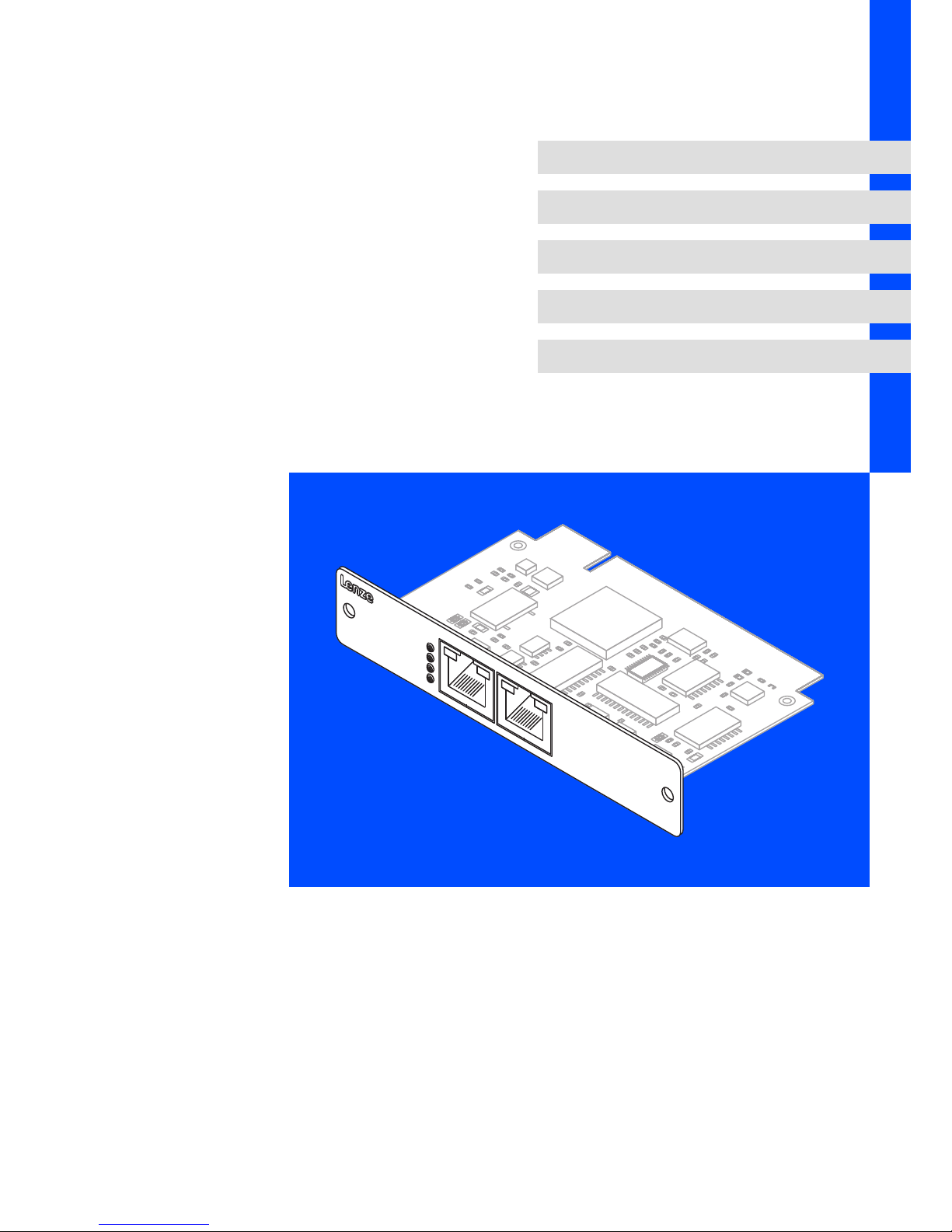
BA_MC−Card
.N*{
Ä.N*{ä
Operating Instructions
Industrial PC
l
MC−xxx
MC card
L−force Controls
MC-PNx
ACTIVE
LINK
RJSS-5381
RJSS-5381
SYS
ST0
ST1
ST2
Page 2

, Before you start working, read ...
ƒ these instructions
ƒ the operating instructions for the standard device
Follow the enclosed safety instructions!
The sets of documentation are part of the "PC−based Automation" and
"Controller−based Automation" manual collection which you can find on the DVDs of
the same name, or on the Internet at http://www.Lenze.com in the "Services &
Downloads" area.
Page 3

Contents i
l 3
BA_MC−Card EN 1.0
1 About this documentation 4. . . . . . . . . . . . . . . . . . . . . . . . . . . . . . . . . . . . . . . . . . . . . . . . . .
1.1 Validity information 4. . . . . . . . . . . . . . . . . . . . . . . . . . . . . . . . . . . . . . . . . . . . . . . . . .
1.2 Target group 4. . . . . . . . . . . . . . . . . . . . . . . . . . . . . . . . . . . . . . . . . . . . . . . . . . . . . . . .
1.3 Document history 4. . . . . . . . . . . . . . . . . . . . . . . . . . . . . . . . . . . . . . . . . . . . . . . . . . . .
1.4 Conventions used 5. . . . . . . . . . . . . . . . . . . . . . . . . . . . . . . . . . . . . . . . . . . . . . . . . . . .
1.5 Notes used 6. . . . . . . . . . . . . . . . . . . . . . . . . . . . . . . . . . . . . . . . . . . . . . . . . . . . . . . . . .
2 Safety instructions 7. . . . . . . . . . . . . . . . . . . . . . . . . . . . . . . . . . . . . . . . . . . . . . . . . . . . . . . . .
3 Product description 8. . . . . . . . . . . . . . . . . . . . . . . . . . . . . . . . . . . . . . . . . . . . . . . . . . . . . . . .
3.1 Scope of supply 8. . . . . . . . . . . . . . . . . . . . . . . . . . . . . . . . . . . . . . . . . . . . . . . . . . . . . .
3.2 Identification 8. . . . . . . . . . . . . . . . . . . . . . . . . . . . . . . . . . . . . . . . . . . . . . . . . . . . . . . .
3.3 Variants 9. . . . . . . . . . . . . . . . . . . . . . . . . . . . . . . . . . . . . . . . . . . . . . . . . . . . . . . . . . . .
3.3.1 Overview 9. . . . . . . . . . . . . . . . . . . . . . . . . . . . . . . . . . . . . . . . . . . . . . . . . . . .
3.3.2 MC−CAN2 10. . . . . . . . . . . . . . . . . . . . . . . . . . . . . . . . . . . . . . . . . . . . . . . . . . . .
3.3.3 MC−ETC, MC−ETH 12. . . . . . . . . . . . . . . . . . . . . . . . . . . . . . . . . . . . . . . . . . . . .
3.3.4 MC−ISI 14. . . . . . . . . . . . . . . . . . . . . . . . . . . . . . . . . . . . . . . . . . . . . . . . . . . . . .
3.3.5 MC−PBM, MC−PBS 16. . . . . . . . . . . . . . . . . . . . . . . . . . . . . . . . . . . . . . . . . . . . .
3.3.6 MC−PNC, MC−PND 19. . . . . . . . . . . . . . . . . . . . . . . . . . . . . . . . . . . . . . . . . . . .
4 Electrical installation 23. . . . . . . . . . . . . . . . . . . . . . . . . . . . . . . . . . . . . . . . . . . . . . . . . . . . . . .
4.1 Important notes 23. . . . . . . . . . . . . . . . . . . . . . . . . . . . . . . . . . . . . . . . . . . . . . . . . . . . . .
4.2 Mounting 23. . . . . . . . . . . . . . . . . . . . . . . . . . . . . . . . . . . . . . . . . . . . . . . . . . . . . . . . . . .
4.3 Wiring and Configuration 24. . . . . . . . . . . . . . . . . . . . . . . . . . . . . . . . . . . . . . . . . . . . .
4.3.1 MC−CAN2 24. . . . . . . . . . . . . . . . . . . . . . . . . . . . . . . . . . . . . . . . . . . . . . . . . . . .
4.3.2 MC−ETC, MC−ETH 28. . . . . . . . . . . . . . . . . . . . . . . . . . . . . . . . . . . . . . . . . . . . .
4.3.3 MC−ISI 30. . . . . . . . . . . . . . . . . . . . . . . . . . . . . . . . . . . . . . . . . . . . . . . . . . . . . .
4.3.4 MC−PBM, MC−PBS 33. . . . . . . . . . . . . . . . . . . . . . . . . . . . . . . . . . . . . . . . . . . . .
4.3.5 MC−PNC, MC−PND 38. . . . . . . . . . . . . . . . . . . . . . . . . . . . . . . . . . . . . . . . . . . .
5 Appendix 43. . . . . . . . . . . . . . . . . . . . . . . . . . . . . . . . . . . . . . . . . . . . . . . . . . . . . . . . . . . . . . . .
5.1 Use of the PCAN view/PCAN Explorer with MC−CAN2 43. . . . . . . . . . . . . . . . . . . . . .
5.2 Contact data of system partners 44. . . . . . . . . . . . . . . . . . . . . . . . . . . . . . . . . . . . . . . .
Page 4

About this documentation
Validity information
1
l
4
BA_MC−Card EN 1.0
0Fig. 0Tab. 0
1 About this documentation
1.1 Validity information
These instructions are valid for
ƒ MC−CAN2 (dual CAN controller) from version 01
ƒ MC−ETH (Ethernet controller) as of version 01
ƒ MC−ETC (EtherCAT controller) as of version 01
ƒ MC−ISI (serial interfaces) from version 01
ƒ MC−PBM (PROFIBUS master) from version 01
ƒ MC−PBS (PROFIBUS slave) from version 01
ƒ MC−PNC (PROFINET controller ) as of version 01
ƒ MC−PND (PROFINET device) as of version 01
1.2 Target group
This documentation is directed at qualified skilled personnel according to IEC 60364.
Qualified skilled personnel are persons who have the required qualifications to carry out
all activities involved in installing, mounting, commissioning, and operating the product.
I Tip!
Information and auxiliary devices related to the Lenze products can be found
in the download area at
http://www.Lenze.com
1.3 Document history
Material number Version Description
.N*{ 1.0 11/2013 TD29 First edition
Page 5
About this documentation
Conventions used
1
l
5
BA_MC−Card EN 1.0
1.4 Conventions used
Type of information Identification Examples/notes
Spelling of numbers
Decimal separator
Point In general, the decimal point is used.
For instance: 1234.56
Warnings
UL warnings
J
Given in English and French
UR warnings
O
Text
Program name » « PC software
For example: »Engineer«, »Global Drive
Control« (GDC)
Icons
Page reference ^ Reference to another page with additional
information
For instance: ^ 16 = see page 16
Documentation reference , Reference to another documentation with
additional information
For example: , EDKxxx = see
documentation EDKxxx
Page 6
About this documentation
Notes used
1
l
6
BA_MC−Card EN 1.0
1.5 Notes used
The following pictographs and signal words are used in this documentation to indicate
dangers and important information:
Safety instructions
Structure of safety instructions:
} Danger!
(characterises the type and severity of danger)
Note
(describes the danger and gives information about how to prevent dangerous
situations)
Pictograph and signal word Meaning
{ Danger!
Danger of personal injury through dangerous electrical voltage.
Reference to an imminent danger that may result in death or
serious personal injury if the corresponding measures are not
taken.
} Danger!
Danger of personal injury through a general source of danger.
Reference to an imminent danger that may result in death or
serious personal injury if the corresponding measures are not
taken.
( Stop!
Danger of property damage.
Reference to a possible danger that may result in property
damage if the corresponding measures are not taken.
Application notes
Pictograph and signal word Meaning
) Note!
Important note to ensure troublefree operation
I Tip!
Useful tip for simple handling
,
Reference to another documentation
Special safety instructions and application notes
Pictograph and signal word Meaning
J Warnings!
Safety note or application note for the operation according to
UL or CSA requirements.
The measures are required to meet the requirements according
to UL or CSA.
O Warnings!
Page 7

Safety instructions 2
l
7
BA_MC−Card EN 1.0
2 Safety instructions
} Danger!
Disregarding the following basic safety measures may lead to severe personal
injury and damage to material assets!
ƒ Lenze drive and automation components ...
... must only be used for the intended purpose.
... must never be operated if damaged.
... must never be subjected to technical modifications.
... must never be operated unless completely assembled.
... must never be operated without the covers/guards.
... can − depending on their degree of protection − have live, movable or rotating parts
during or after operation. Surfaces can be hot.
ƒ All specifications of the corresponding enclosed documentation must be observed.
This is vital for a safe and trouble−free operation and for achieving the specified product
features.
The procedural notes and circuit details provided in this document are proposals which
the user must check for suitability for his application. The manufacturer does not
accept any liability for the suitability of the specified procedures and circuit proposals.
ƒ Only qualified skilled personnel are permitted to work with or on Lenze drive and
automation components.
According to IEC 60364 or CENELEC HD 384, these are persons ...
... who are familiar with the installation, assembly, commissioning and operation of
the product,
... possess the appropriate qualifications for their work,
... and are acquainted with and can apply all the accident prevent regulations, directives
and laws applicable at the place of use.
Page 8

Product description
Scope of supply
3
l
8
BA_MC−Card EN 1.0
3 Product description
3.1 Scope of supply
NumberName
1 MC card
1 Mounting Instructions
) Note!
After receipt of the delivery, check immediately whether the items match the
accompanying papers. We do not accept any liability for deficiencies claimed
subsequently.
Claim
ƒ visible transport damage immediately to the forwarder
ƒ visible deficiencies/incompleteness immediately to your Lenze
representative.
3.2 Identification
Type code MC − xxx − xx
Module Card
CAN2 = dual CAN controller
ETC = EtherCAT controller
ETH = Ethernet controller
ISI = serial interfaces
PBM = PROFIBUS master
PBS = PROFIBUS slave
PNC = PROFINET controller
PND = PROFINET device
Version
Page 9
Product description
Variants
Overview
3
l
9
BA_MC−Card EN 1.0
3.3 Variants
3.3.1 Overview
MC card Function For the use with
MC−CAN2 For connection to a CAN fieldbus;
the card features 2 independent
CAN interfaces
l IPC 3241 C
l IPC CPC 2800
l IPC CS 5800 − 9800
l IPC EL 1800 − 9800
l Controller 3200 C
l Controller p500
MC−ETC For connection to a EtherCAT
network
l IPC 3241 C
l IPC CPC 2800
l IPC CS 5800 − 9800
l IPC EL 1800 − 9800
MC−ETH For connection to a Ethernet
network
l IPC 3241 C
l IPC CPC 2800
l IPC CS 5800 − 9800
l IPC EL 1800 − 9800
MC−ISI For the connection to RS 232,
RS 422, or RS 485; the card has 2
independent serial interfaces
l IPC 3241 C
l IPC CPC 2800
l IPC CS 5800 − 9800
l IPC EL 1800 − 9800
l Controller 3200 C
l Controller p500
MC−PBM For connection to a PROFIBUS
system as master
l IPC 3241 C
l IPC CPC 2800
l IPC CS 5800 − 9800
l IPC EL 1800 − 9800
l Controller 3200 C
l Controller p500
MC−PBS For connection to a PROFIBUS
system as slave
l IPC 3241 C
l IPC CPC 2800
l IPC CS 5800 − 9800
l IPC EL 1800 − 9800
l Controller 3200 C
l Controller p500
MC−PNC For connection to a PROFINET
system as control system (controller
interface connection)
l IPC 3241 C
l IPC CPC 2800
l IPC CS 5800 − 9800
l IPC EL 1800 − 9800
l Controller 3200 C
l Controller p500
MC−PND For connection to a PROFINET
system as device (device interface
connection)
l IPC 3241 C
l IPC CPC 2800
l IPC CS 5800 − 9800
l IPC EL 1800 − 9800
l Controller 3200 C
l Controller p500
Page 10
Product description
Variants
MC−CAN2
3
l
10
BA_MC−Card EN 1.0
3.3.2 MC−CAN2
Application as directed
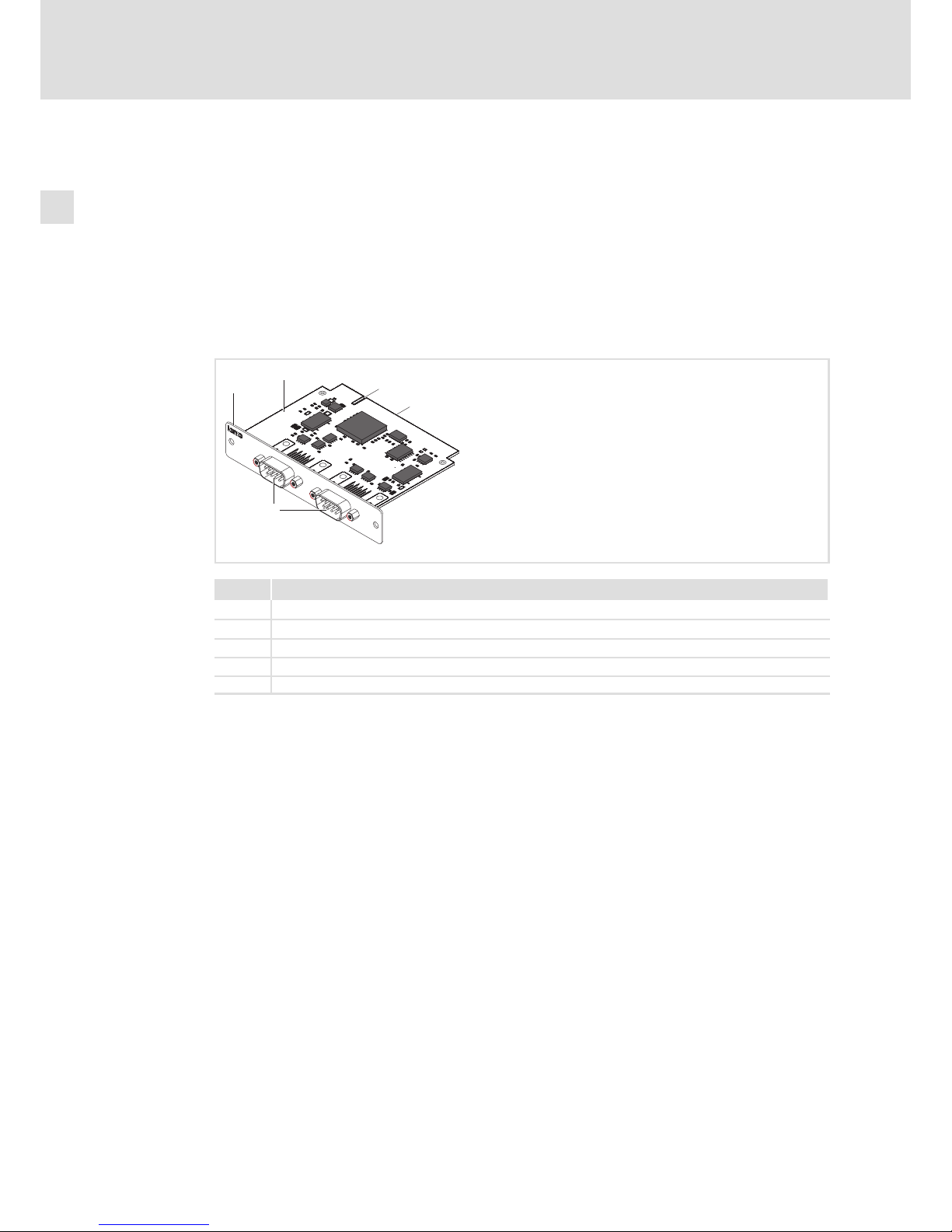
The MC−CAN2 is a plug−in card for the connection of a Lenze device to a CAN fieldbus. It
provides 2 independent CAN interfaces.
The MC card is used as directed if it is solely used in lenze device with MC card interface. A
different use, or one beyond these purposes, is not permissible.
Elements
CAN2
CAN2
CAN1
MC-
0
1
3
4
2
MC−CAN2−001
Pos. Description
0 Front panel
1 Printed circuit board
2 Coding
3 Standard device connection
4 Bus system connection
Page 11
Product description
Variants
MC−CAN2
3
l
11
BA_MC−Card EN 1.0
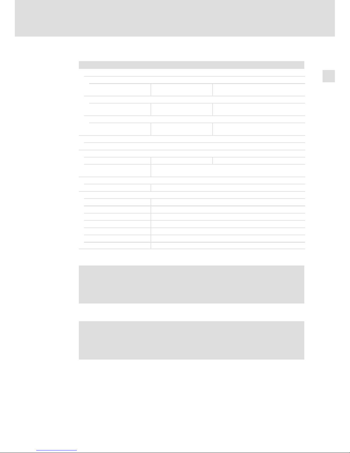
Technical data
MC−CAN2
Conformity, approval, directive
Conformity
CE EN 61000−6−4
EN 61000−6−2
EMC Directive Class A,
industrial premises
Approval
UR UL 508
CSA C22.2
Process Control Equipment
(File−No. E236341)
Directive
RoHS − Products lead−free in accordance with CE
Directive 2011/65/EU
General data and operating conditions
See standard device
Electrical data
Current < 0.2 A at standard device supply voltage of 24 V
Electrical isolation to the
fieldbus
yes
Mechanical data
Mass < 0.1 kg
Communication
Type CAN, ISO011898
Protocol CAN
Topology Line, terminated on both sides with 120 W
Node Master or Slave
Number of nodes max. 63
Max. baud rate 1 MBaud
Bus length ^ CAN communication manual
¸
O Warnings!
Use only together with appropriate cable connectors, provided with screws for
securement and secure connector to avoid loosening.
For use in controlled environment only.
¹
O Warnings!
A utiliser exclusivement avec des connecteurs de câble à vis adaptés. Fixer les
connecteurs pour éviter toute déconnexion.
Destiné uniquement à des zones à environnement contrôlé.
Page 12
Product description
Variants
MC−ETC, MC−ETH
3
l
12
BA_MC−Card EN 1.0
3.3.3 MC−ETC, MC−ETH
Application as directed
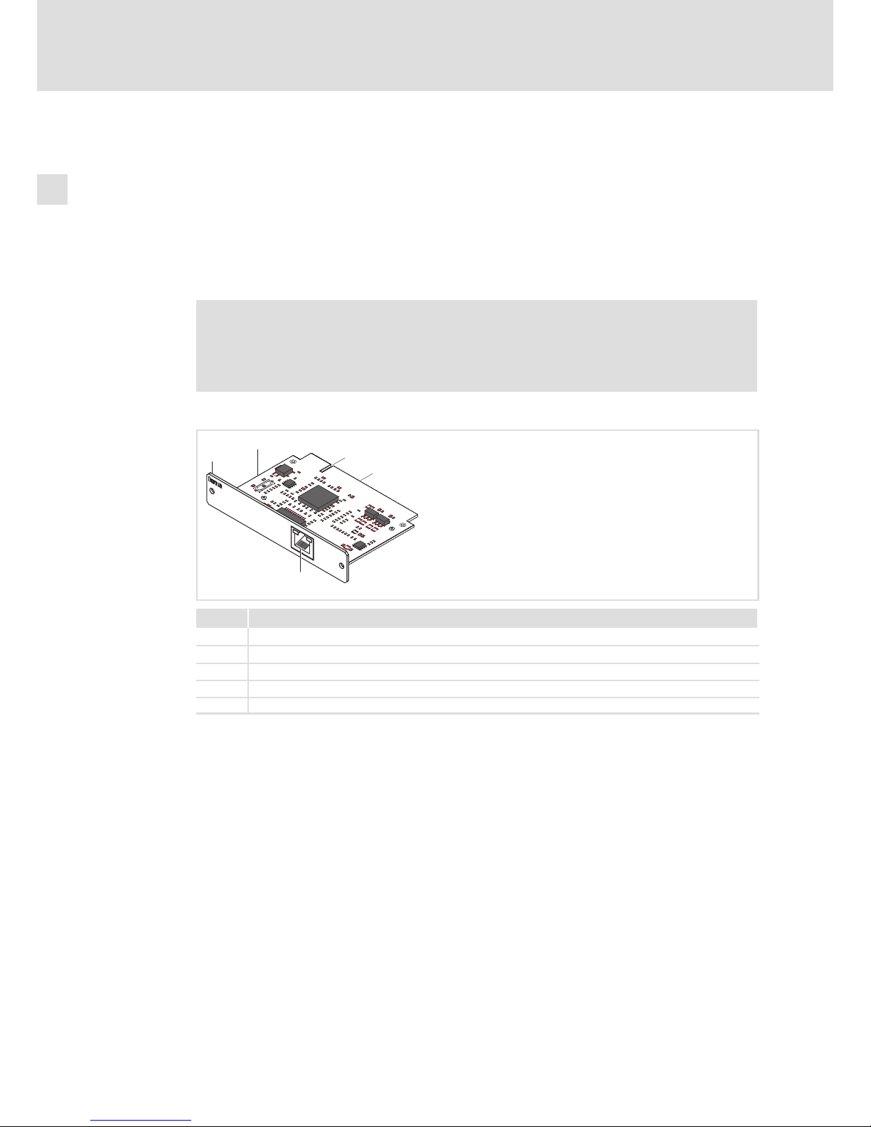
The MC−ETH is a plug−in card for connecting a Lenze device to a Ethernet network.
The MC−ETC is a plug−in card for connecting a Lenze device as master to a EtherCAT
network.
The MC card is used as directed if it is solely used in lenze device with MC card interface. A
different use, or one beyond these purposes, is not permissible.
) Note!
This is a device of class A. It can cause radio interference in residential areas. In
this case, the operator may have to take special measures. Any costs arising
from these measures must be paid by the operator.
Elements
0
1
3
2
SPEED
LINK
LA
N
MC-ETH
RJSS-5381
4
MC−ETH−001
Pos. Description
0 Front panel
1 Printed circuit board
2 Coding
3 Standard device connection
4 Network connection
Page 13
Product description
Variants
MC−ETC, MC−ETH
3
l
13
BA_MC−Card EN 1.0
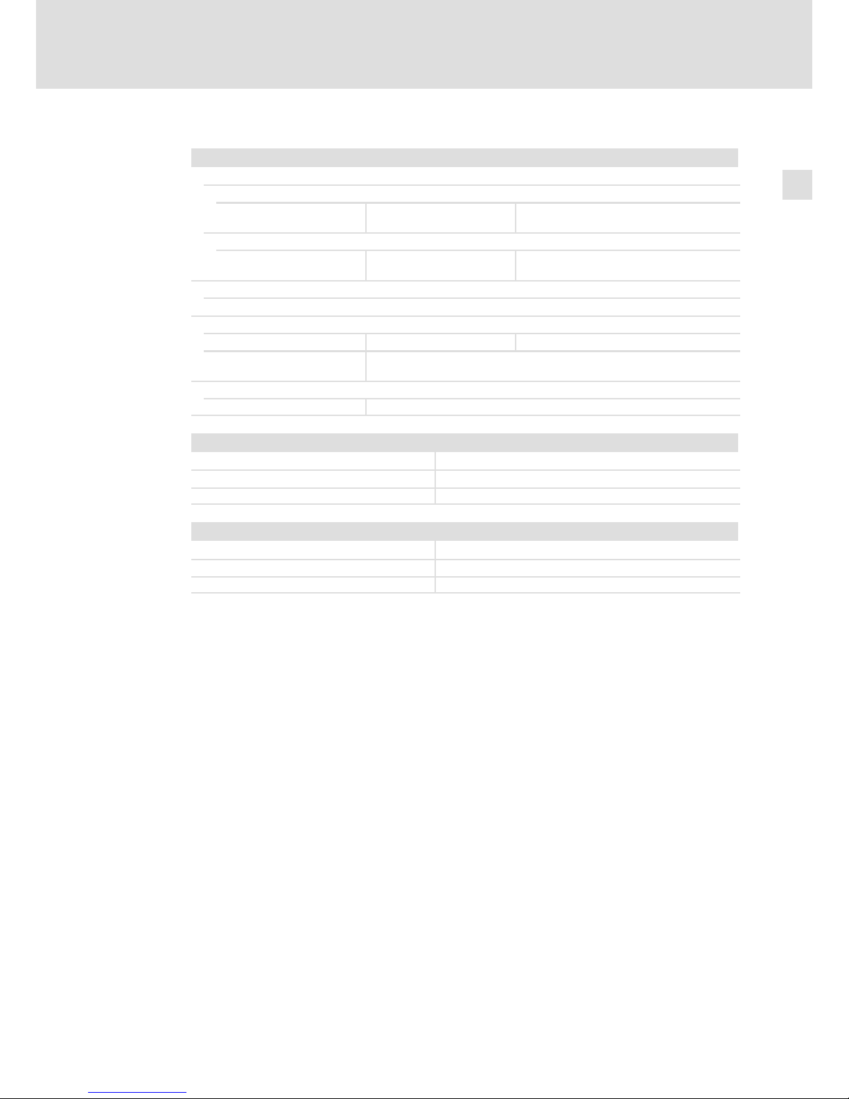
Technical data
MC−ETH, MC−ETC
Conformity, directive
Conformity
CE EN 61000−6−4
EN 61000−6−2
EMC Directive Class A,
industrial premises
Directive
RoHS − Products lead−free in accordance with CE
Directive 2011/65/EU
General data and operating conditions
See standard device
Electrical data
Current < 0.2 A at standard device supply voltage of 24 V
Electrical isolation to the
fieldbus
yes
Mechanical data
Mass < 0.1 kg
MC−ETH
Protocol TCP/IP
Baud rate 10/100/1000 Mbits
Connection RJ45 socket to EN 50173
MC−ETC
Protocol EtherCAT
Baud rate 100 Mbits
Connection RJ45 socket to EN 50173
Page 14
Product description
Variants
MC−ISI
3
l
14
BA_MC−Card EN 1.0
3.3.4 MC−ISI
Application as directed
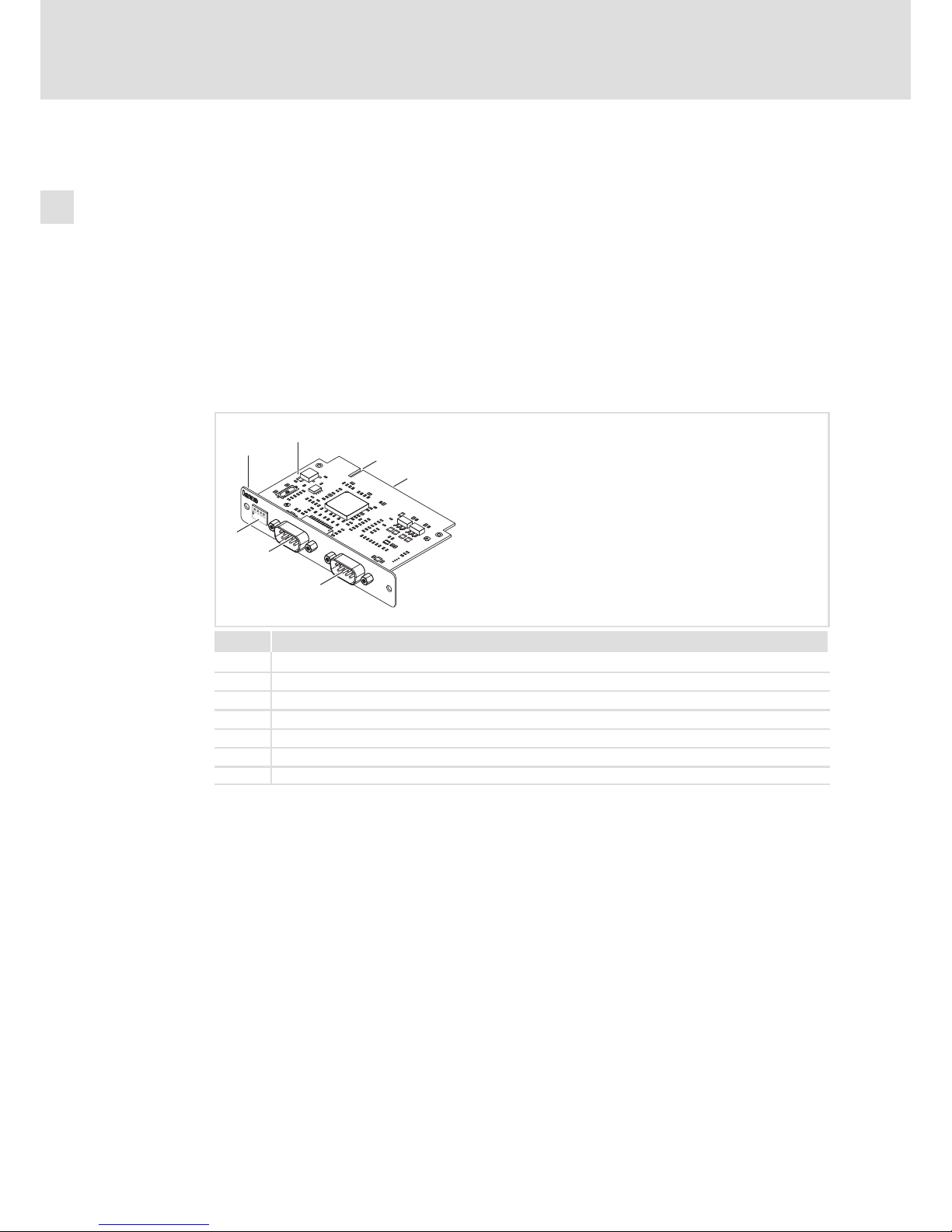
The MC−ISI is a plug−in card via which a Lenze device can exchange serial data with
peripheral devices.
It provides two independent, electrically isolated interfaces.
ƒ COM A: RS232
ƒ COM B: RS422 or RS485 (switchable)
The MC card is used as directed if it is solely used in lenze device with MC card interface. A
different use, or one beyond these purposes, is not permissible.
Elements
MC-ISI
12
34
ON
0
1
3
2
6
5
4
MC−ISI_001
Pos. Description
0 Front panel
1 Printed circuit board
2 Coding
3 Standard device connection
4 COM A connection (RS232)
5 COM B connection (RS422/RS485)
6 DIP switch
Page 15
Product description
Variants
MC−ISI
3
l
15
BA_MC−Card EN 1.0
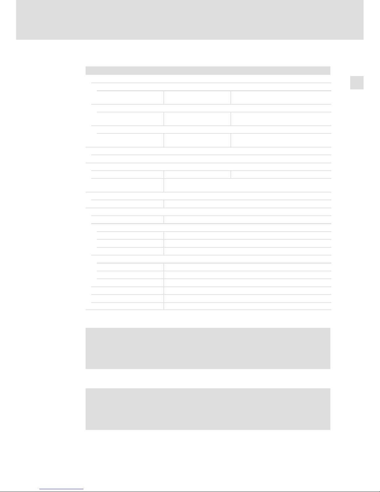
Technical data
MC−ISI
Conformity, approval, directive
Conformity
CE EN 61000−6−4
EN 61000−6−2
EMC Directive Class A,
industrial premises
Approval
UR UL 508
CSA C22.2
Process Control Equipment
(File−No. E236341)
Directive
RoHS − Products lead−free in accordance with CE
Directive 2011/65/EU
General data and operating conditions
See standard device
Electrical data
Current < 0.2 A at standard device supply voltage of 24 V
Electrical isolation to the
fieldbus
yes
Mechanical data
Mass < 0.1 kg
Communication
Type Serial interface
COM A
Type RS232, electrically isolated
Isolation 2.500 Vrms
ESD protection 15 kV
COM B
Type RS422/485 (switchable), electrically isolated
Isolation 2.500 Vrms
ESD protection 15 kV
Baud rate 600 Baud ... 115.2 kBaud
Data frame 5, 6, 7, 8 and 9 Bit
Parity Even, odd, none, space & mark
¸
O Warnings!
Use only together with appropriate cable connectors, provided with screws for
securement and secure connector to avoid loosening.
For use in controlled environment only.
¹
O Warnings!
A utiliser exclusivement avec des connecteurs de câble à vis adaptés. Fixer les
connecteurs pour éviter toute déconnexion.
Destiné uniquement à des zones à environnement contrôlé.
Page 16
Product description
Variants
MC−PBM, MC−PBS
3
l
16
BA_MC−Card EN 1.0
3.3.5 MC−PBM, MC−PBS
Application as directed
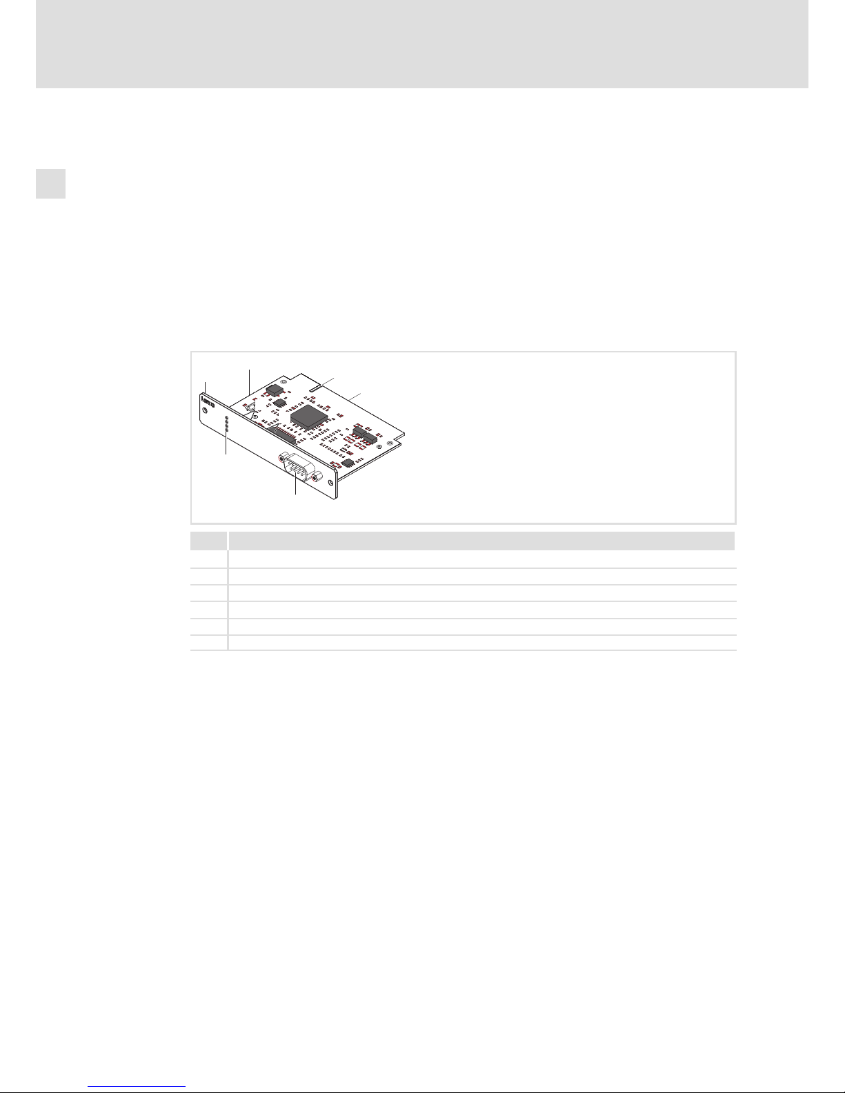
The MC−PBM and MC−PBS are plug−in cards for connecting a Lenze device to a PROFIBUS
system.
Whereas the slave interface connection (MC−PBS) serves to address the device as a node
under a PROFIBUS control, the master interface connection (MC−PBM) serves to enable the
user to establish a control on the basis of PROFIBUS.
The MC card is used as directed if it is solely used in lenze device with MC card interface. A
different use, or one beyond these purposes, is not permissible.
Elements
0
1
3
2
6
6
PROFIBUS
MC-PNx
SYS
ST0
ST1
ST2
5
4
MC−PBx−001
Pos. Description
0 Front panel
1 Printed circuit board
2 Coding
3 Standard device connection
4 Fieldbus connection
5 Status LEDs
Page 17
Product description
Variants
MC−PBM, MC−PBS
3
l
17
BA_MC−Card EN 1.0
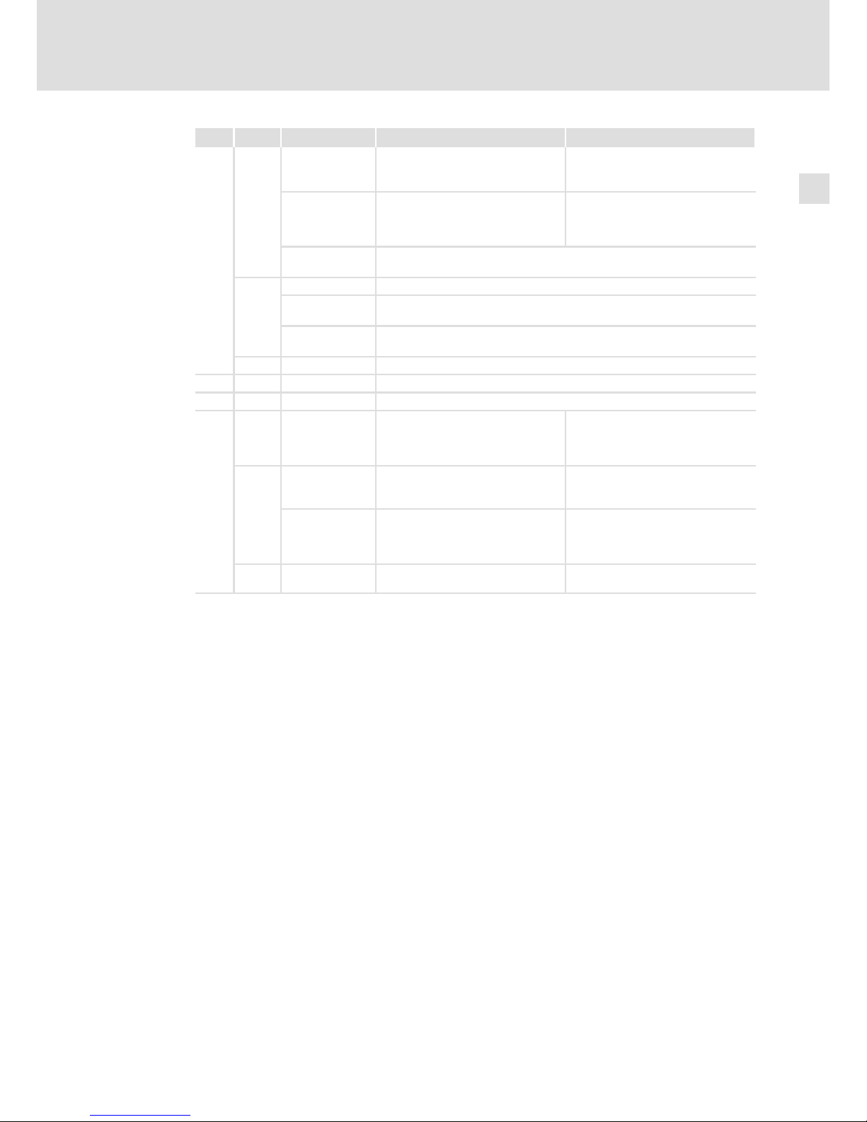
LED Colour Status Meaning at MC−PBM Meaning at MC−PBS
SYS Green
On Communication is running, the
device has at least established a
connection to one configured node
Slave is in cyclic data exchange with
DP master
Blinking with 5
Hz
No error within configuration,
communication has stopped, or
ready for communication, but no
connection to a slave
Slave has no cyclic data exchange
with DP master
Is blinking
irregularly
Start−up: No or incorrect configuration, commissioning required; runtime:
host−watchdog time error
Yellow
Blinking with 1Hz Device is in bootstraploader mode and is waiting for firmware download
Blinking with 5
Hz
Firmware download is carried out
Is blinking
irregularly
Hardware or fatal system error detected
− Off Supply voltage for the device is missing, or hardware is defective
ST0 − − No function
ST1 − − No function
ST2
Red On Device has a communication
problem with at least one
PROFIBUS−DP slave or has detected a
short circuit
Application program
(communication mode: synchronous
to bus/device−controlled) is no
longer synchronous to the bus cycle
Yellow
Is blinking
irregularly
Device is within the PROFIBUS ring
and shares the token with other
PROFIBUS master devices
−
On Device holds the PROFIBUS token
and can transmit telegrams
Slave has received
parameter/configuration data from
the DP master and has reached the
DataExchange state
− Off Connection to Ethernet exists. Slave has not reached the
DataExchange state
Page 18

Product description
Variants
MC−PBM, MC−PBS
3
l
18
BA_MC−Card EN 1.0
Technical data
MC−PBM, MC−PBS
Conformity, approval, directive
Conformity
CE EN 61000−6−4
EN 61000−6−2
EMC Directive Class A,
industrial premises
Approval
UR UL 508
CSA C22.2
Process Control Equipment
(File−No. E236341)
Directive
RoHS − Products lead−free in accordance with CE
Directive 2011/65/EU
General data and operating conditions
See standard device
Electrical data
Current < 0.2 A at standard device supply voltage of 24 V
Electrical isolation to the
fieldbus
yes
Mechanical data
Mass < 0.1 kg
Communication
Type PROFIBUS−DP, ISO 7498
Protocol PROFIBUS−DP
Topology Line, system
Node MC−PBM (Master) / MC−PBS (Slave)
Max. number of nodes per
segment
max. 32
Max. number of nodes per
system
max. 128
Baud rate
^ 24
Bus length
¸
O Warnings!
Use only together with appropriate cable connectors, provided with screws for
securement and secure connector to avoid loosening.
For use in controlled environment only.
¹
O Warnings!
A utiliser exclusivement avec des connecteurs de câble à vis adaptés. Fixer les
connecteurs pour éviter toute déconnexion.
Destiné uniquement à des zones à environnement contrôlé.
Page 19
Product description
Variants
MC−PNC, MC−PND
3
l
19
BA_MC−Card EN 1.0
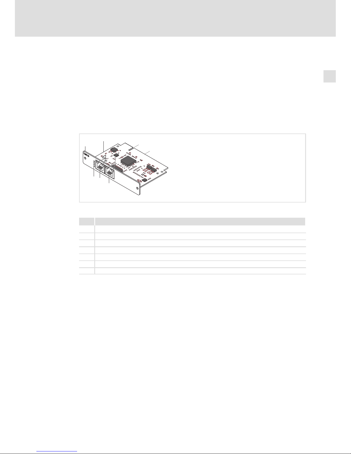
3.3.6 MC−PNC, MC−PND
Application as directed
The MC−PNC and MC−PND are plug−in cards for connecting a Lenze device to a PROFINET
system.
Whereas the device interface connection (MC−PND) serves to activate the device as a node
under a PROFINET control, the controller interface connection (MC−PNC) serves to establish
an individual control system on the basis of PROFINET.
The MC card is used as directed if it is solely used in lenze device with MC card interface. A
different use, or one beyond these purposes, is not permissible.
0
1
3
2
ACTIVE
LINK
PRO
FI
NET
MC-PNx
RJSS-5381
RJSS-5381
SYS
ST0
ST1
ST2
4
4
5
6
6
MC−PNx−001
Elements
Pos. Description
0 Front panel
1 Printed circuit board
2 Coding
3 Standard device connection
4 Bus system connection
5 Status LEDs
6 Link /Active LED
Page 20
Product description
Variants
MC−PNC, MC−PND
3
l
20
BA_MC−Card EN 1.0
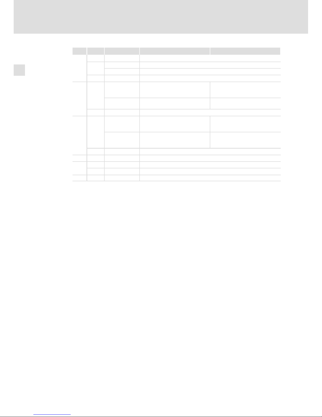
LED Colour Status Meaning at MC−PNC Meaning at MC−PND
SYS
Green
On Operating system is running
Yellow
Blinking with 1Hz Error during boot process
On Boot loader waits for boot process
− Off No supply voltage or defect hardware
ST0 Red
On Together with ST1 "Red On": no valid
master licence
System error:
Watchdog time−out; channel, generic
or extended diagnostics is available
Blinking with 2
Hz
System error:
invalid configuration
DCP signal service is enabled via the
bus
− Off No error
ST1 Red
On No connection/no link. Or (together
with ST0 "Red On") no valid master
licence
No configuration or slow physical
connection or no physical connection
Blinking with 2
Hz
Configuration error: Not all
configured I/O devices are
connected.
No data exchange
− Off No error
ST2 − − No function
Link
Green On Connection to Ethernet exists
− Off No connection to Ethernet
Active Yellow Blinking Device transmits/receives Ethernet frames
Page 21
Product description
Variants
MC−PNC, MC−PND
3
l
21
BA_MC−Card EN 1.0
Technical data
MC−PNC, MC−PND
Conformity, approval, directive
Conformity
CE EN 61000−6−4
EN 61000−6−2
EMC Directive Class A,
industrial premises
Approval
UR UL 508
CSA C22.2
Process Control Equipment
(File−No. E236341)
Directive
RoHS − Products lead−free in accordance with CE
Directive 2011/65/EU
General data and operating conditions
See standard device
Electrical data
Current < 0.2 A at standard device supply voltage of 24 V
Electrical isolation to the
fieldbus
yes
Mechanical data
Mass < 0.1 kg
MC−PNC (controller)
I/O data
l Configurable up to max. 5760 bytes input
l Configurable up to max. 5760 bytes output
Data transport l Ethernet frames
Communication l PROFINET IO−RT
– cyclic and acyclic
Acyclic data l Read, write, record: max. 1 kbyte/request
l Alarms
Functions l Cyclic process data
l Buffering host−controlled data exchange of cyclic data
l Minimum cycle time: 1 ms
l Different cycle times are configurable for different devices
l Max. 32 devices can be configured
l DCP
l Context management via CL−RPC
l One buffer is available per device for diagnostic data
Special features l No support for
– RT over UDP
– Multicast communication
– DHCP
l Only one IOCR1 per IO device is possible, IOCR data length:
1024 bytes
l Max. number of the connectable IO devices decreases to
25 when cycle times lower than 4 ms are used.
l NameOfStation of the IO controller cannot be set via the
DCP Set NameOfStation service but only by the
configuration during the start
Page 22
Product description
Variants
MC−PNC, MC−PND
3
l
22
BA_MC−Card EN 1.0
MC−PND (device)
I/O data
l Configurable up to max. 1024 bytes input
l Configurable up to max. 1024 bytes output
Communication l PROFINET IO−RT
– VLAN and priority tagging
– cyclic and acyclic
Functions l Cyclic process data
l Acyclic read and write requests
l Process and diagnostic alarm: 200 bytes
l DCP
l Context management via CLRPC
l Generic diagnostics, channel diagnostics, extended
channel diagnostics: 200 bytes
l Comparison of the setpoints / actual values of the
configuration
Special features l Maximum number of modules: 244
l Maximum number of submodules: 1
l No support for
– RT over UDP
– Multicast communication
l Only one device instance is supported
¸
O Warnings!
Use only together with appropriate cable connectors, provided with screws for
securement and secure connector to avoid loosening.
For use in controlled environment only.
¹
O Warnings!
A utiliser exclusivement avec des connecteurs de câble à vis adaptés. Fixer les
connecteurs pour éviter toute déconnexion.
Destiné uniquement à des zones à environnement contrôlé.
Page 23
Electrical installation
Important notes
4
l
23
BA_MC−Card EN 1.0
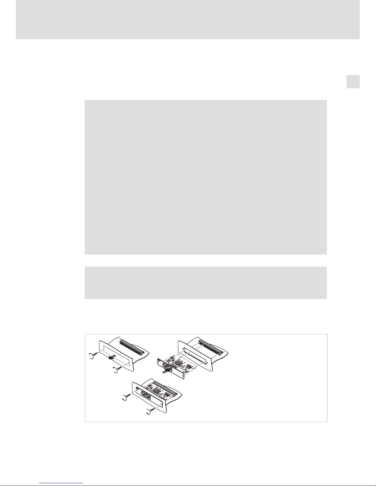
4 Electrical installation
4.1 Important notes
( Stop!
Short circuit and static discharges
The printed circuit board and the standard device contain components which
are endangered in the case of short circuit or static discharge.
Possible consequences:
ƒ The printed circuit board or devices connected are destroyed.
Protective measures:
ƒ For all operations on the printed circuit board, the latter as well as the
standard device have to be in a deenergised state. This in particular applies
to the connection/disconnection of the printed circuit board and the
connection/disconnection of connectors.
ƒ All persons handling printed circuit boards must regard ESD measures.
ƒ Connector contacts must not be touched.
ƒ Printed circuit boards must only be touched in contact−free places and must
only be placed on suitable bases (e. g. on ESD packaging or conductive
foamed material).
ƒ Printed circuit boards must only be transported and stored in ESD
packaging.
) Note!
For mounting the unit, the housing of the industrial PC has to be opened
(^ documentation for the standard device).
4.2 Mounting
SPEED
MC-ETH
R
J
S
S
-5
3
8
1
RJSS-5381
SPEED
LINK
LA
N
MC-ETH
R
J
S
S
-5
3
8
1
RJSS-5381
ACTIVE
LINK
PROFINET
MC-PNx
R
J
S
S
-
5
3
8
1
RJSS-5381
R
J
S
S
-
5
3
8
1
RJSS-5381
SYS
ST0
ST1
ST2
LINK
LA
N
ACTIVE
LINK
PROFINET
MC-PNx
R
J
S
S
-
5
3
8
1
RJSS-5381
R
J
S
S
-
5
3
8
1
RJSS-5381
SYS
ST0
ST1
ST2
MC−PNx−002
Page 24
Electrical installation
Wiring and Configuration
MC−CAN2
4
l
24
BA_MC−Card EN 1.0
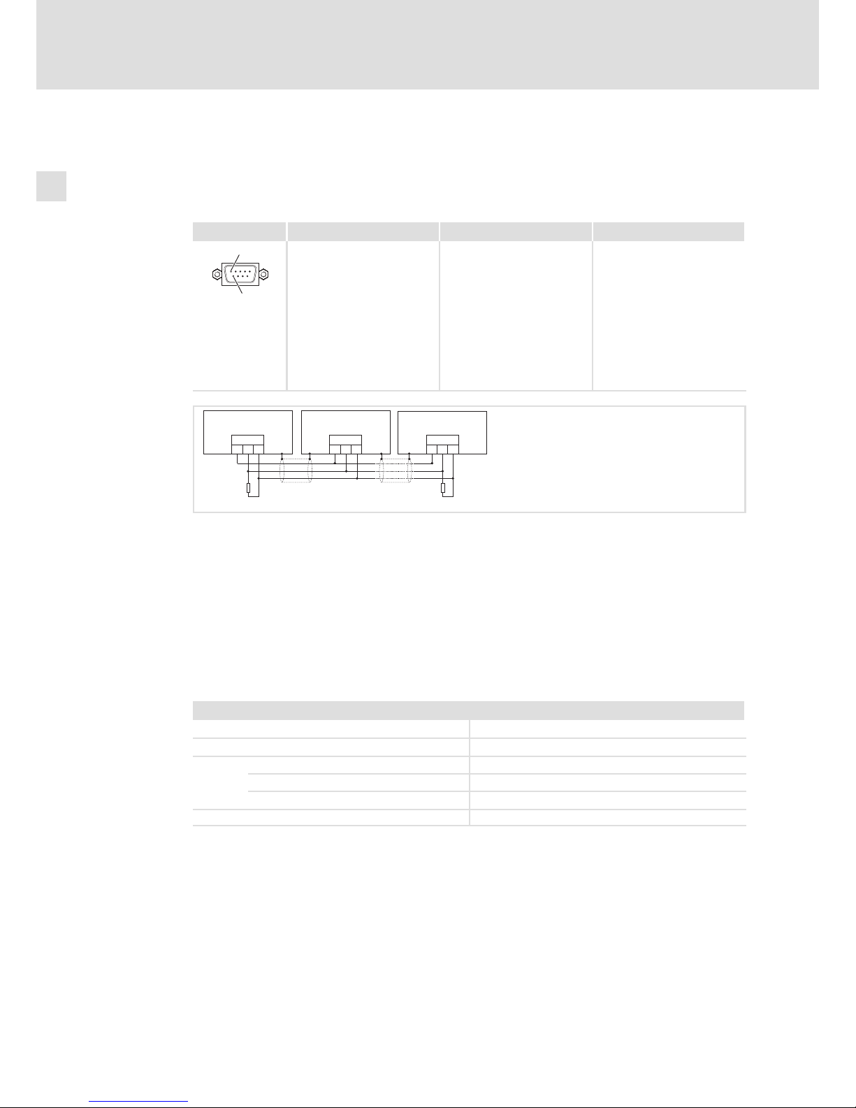
4.3 Wiring and Configuration
4.3.1 MC−CAN2
Wiring
Pin assignment Description Connection type Cable type
1
6
CAN bus connection
Pin 1: not assigned
Pin 2: CAN−LOW (LO)
Pin 3: CAN−GND (CG)
Pin 4: not assigned
Pin 5: not assigned
Pin 6: CAN−GND (CG)
Pin 7: CAN−HIGH (HI)
Pin 8: not assigned
Pin 9: not assigned
9−pole SUB−D plug See following table
MC−CAN−003
CG
CAN
LO HI CG
CAN
LO HI CG
CAN
LO HI
RR
A
n
A
2
A
1
EL100−009
A1 Node 1
A2 Node 2
An Node n
CG CAN−GND
LO CAN−LOW
HI CAN−HIGH
R 120 W−bus terminating resistor
Specification of the transmission cable
We recommend the use of CAN cables in accordance with ISO 11898−2:
CAN cable in accordance with ISO 11898−2
Cable type Paired with shielding
Impedance 120 W (95 ... 140 W)
Cable resistance/cross−section
Cable length £ 300 m £ 70 mW/m / 0.25 0.34 mm2 (AWG22)
Cable length 301 1000 m £ 40 mW/m / 0.5 mm2 (AWG20)
Signal propagation delay £ 5 ns/m
Page 25
Electrical installation
Wiring and Configuration
MC−CAN2
4
l
25
BA_MC−Card EN 1.0
Use of the MC card in Windowsâ XP or Windowsâ Embedded Standard 2009
In order to use the communication card in Windowsâ XP, a device driver is required which
is part of the "communication software (CAN)". It is included on the "PC based
Automation" DVD and can also be found at www.Lenze.com in the download area. The
device driver assumes the entire management of the interface.
The following files are installed with the device driver:
ƒ can2bdrv.sys (visible in the Windows device manager as "CAN2 Bus Driver")
ƒ can2fdrv.sys (visible in the Windows device manager as "CAN Device")
ƒ mccan2services.exe (visible in the Windows task manager as "McCAN2 Wrapper
Service")
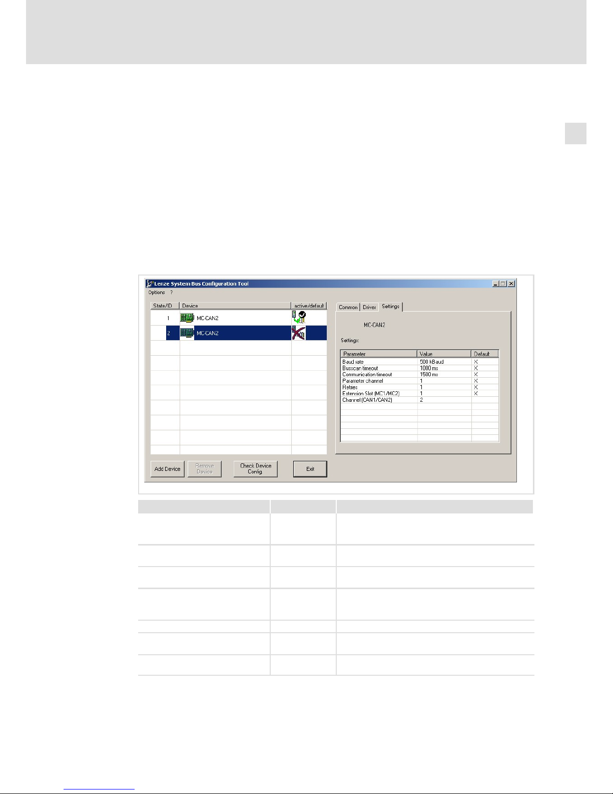
The communication card is configured via the Lenze system bus configurator. The settings
entered there are valid for all applications which communicate via this card.
Parameter Value range Comment
Baud rate 5, 10, 20, 50, 100,
125, 250, 500,
1000
in kbps
Time limit for the node search 0.5 ... 10 s Total time the bus scan is waiting for the feedback of
all nodes
Communication time−out 0.1 ... 10 s Time up to which a CAN node must have responded;
after that an error is reported.
Parameter channel 0, 1, 2 0: CANopen
1: Lenze system bus parameter channel 1
2: Lenze system bus parameter channel 2
Repeat tests 1 ... 10 Repetition of the CAN telegrams in case of an error
Expansion slot (MC1 / MC2) 1, 2 Number of the module card slot at the IPC (see
labelling of the slots at the IPC)
Channel (CAN1 / CAN2) 1, 2 Number of the CAN terminal on the corresponding card
(see labelling at the front panel of the card)
Page 26

Electrical installation
Wiring and Configuration
MC−CAN2
4
l
26
BA_MC−Card EN 1.0
For diagnostic purposes, the following tools are provided on the "PC based Automation"
DVD:
ƒ PCAN view: Simple CAN monitor
ƒ PCAN stat: Status monitor of the device driver
Further information on how to apply these diagnostic programs can be found in the
appendix.
The device driver contains a user interface which can be addressed with the following
tools:
ƒ PCAN Light
A simple DLL interface for accessing max. one communication card MC−CAN2. The API
"PCAN Light" comprises all functions for initialising, parameter setting, exchanging
data, and reading out status information.
The API comes in two DLLs on the "PC based Automation" DVD: PCAN_MC_CAN.DLL
for accessing CAN1 and PCAN_MC_CAN2.DLL for accessing CAN2, hence the CAN
terminals of the first plugged MC−CAN2 card. The access to a second MC−CAN2 card is
not possible with PCAN Light but only by means of the integrated development
environments PCAN Evaluation or PCAN Developer (see below).
Further information on "PCAN Light" can be obtained from the online help for "PCAN
Light" on the "PC based Automation" DVD. There you will also find the source code of
example programs for a quick training.
CAUTION: In order to use "PCAN Light" together with the MC−CAN2 card, you must get
an additional licence. This is coupled with the communication card and made visible by
a licence sticker. Before using "PCAN Light", please check if you have got the required
licence since otherwise you would violate the copyright.
ƒ PCAN Evaluation / PCAN Developer
These complex integrated development environments provide more comprehensive
functions than PCAN Light; e.g.:
– Event operation
– Error frame handling
– Operation of several clients with one hardware
The integrated development environments can be obtained from the Peak company
(¶ 44).
) Note!
Addressing the communication card from your own applications requires
special programming skills. Lenze does not offer any support regarding this
matter.
The communication card is compatible with the technology of Peak (¶ 44).
There you will get the required support.
Page 27

Electrical installation
Wiring and Configuration
MC−CAN2
4
l
27
BA_MC−Card EN 1.0
Use of the MC card in Windowsâ CE
In Windowsâ CE the card interact via control system. All required drivers are installed
) Note!
No special support is provided currently if you use the communication card in
your own applications. For special projects, please contact your sales office.
Page 28
Electrical installation
Wiring and Configuration
MC−ETC, MC−ETH
4
l
28
BA_MC−Card EN 1.0
4.3.2 MC−ETC, MC−ETH
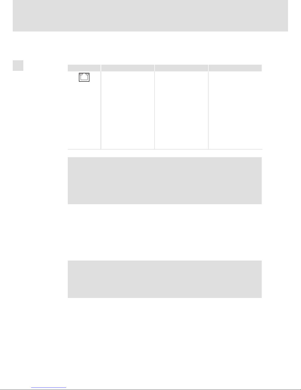
Wiring
Description Connection type Cable type
SPEED
LINK
LAN
MC−ETH port
"Link" LED:
On: Connection OK
Blinking: Data transfer
"Speed" LED:
Off: 10 Mbps
Green: 100 Mbps
Yellow: 1000 Mbps
MC−ETC port
"Link" LED:
On: Connection OK
Blinking: Data transfer
"Speed" LED:
Green: 100 Mbps
RJ45 socket
CAT5 S/UTP or CAT5e S/FTP
(recommended) network
cable, max. cable length
100 m
MC−ETH−003
) Note!
If the RJ45 plug connection is exposed to oscillating or vibrating stress:
ƒ Use a strain relief in the immediate vicinity of the RJ45 socket.
ƒ Select the contact surface on which the device is mounted as fixing point of
the strain relief.
ƒ Comply with the related minimum bending radius of the cable used.
Use of the MC card in Windowsâ XP or Windowsâ Embedded Standard 2009
In order to use the communication card in Windowsâ XP, a device driver is required. It is
already pre−installed and also included on the "PC based Automation" DVD. For the
implementation of the communication card in your own applications, use "WinSockets",
which are provided by corresponding programming systems. A special library is not
required.
) Note!
Addressing the communication card from your own applications requires
special programming skills. Lenze does not offer any support regarding this
matter. However, we can refer you to service providers who execute
customised programming and are familiar with Lenze Industrial PCs.
Page 29

Electrical installation
Wiring and Configuration
MC−ETC, MC−ETH
4
l
29
BA_MC−Card EN 1.0
Use of the MC card in Windowsâ CE
You can use the card in Windowsâ CE only with IPCs, not with controllers.
In order to be able to use the communication card in Windows
â
CE, a device driver is
required. It is already pre−installed. For integrating the communication card into individual
applications, use so−called "WinSockets" which are provided by the corresponding
programming systems. A special library is not required.
Page 30
Electrical installation
Wiring and Configuration
MC−ISI
4
l
30
BA_MC−Card EN 1.0
4.3.3 MC−ISI
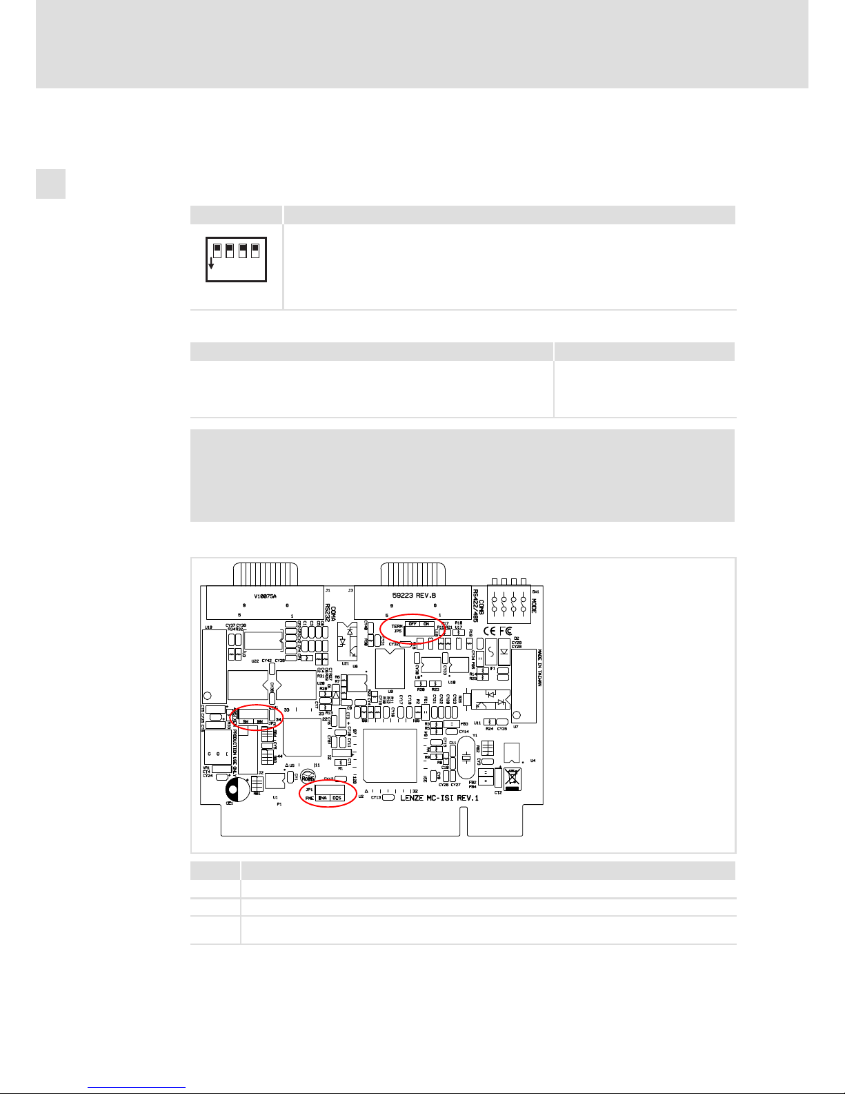
Configuration
DIP switch for setting the mode:
DIP switch Description
1234
ON
Pos. 1 = ON: RS485 mode
Pos. 2 = ON: RS422 mode
Pos. 3 = ON/OFF: four−wire conductor/two−wire conductor (only relevant for RS485 mode)
Pos. 4 = ON/OFF: echo function activated/deactivated (only relevant for RS485 mode +
two−wire conductor)
MC−ISI_004
Set the mode:
Mode DIP switch setting
RS485 mode, two−wire conductor, deactivated echo function (default)
RS485 mode, two−wire conductor, activated echo function
RS485 mode, four−wire conductor
RS422
Pos. 1 = ON
Pos. 1+4 = ON
Pos. 1+3 = ON
Pos. 2 = ON
) Note!
ƒ If switch 1 = ON (RS485), switch 2 must be set to OFF;
if switch 2 = ON (RS422), switch 1 must be set to OFF.
ƒ The echo function monitors the RS485 bus for collisions.
Further settings:
MC−ISI_003
Jumper Function
JP1 plugged−on to ENA: default setting
JP3 plugged−on to HW: default setting
JP5
plugged−on: terminating resistor for RS422−/485 mode activated
open: terminating resistor for RS422−/485 mode deactivated
Do not assign JP2! Lenze service personnel only.
Page 31
Electrical installation
Wiring and Configuration
MC−ISI
4
l
31
BA_MC−Card EN 1.0
Wiring
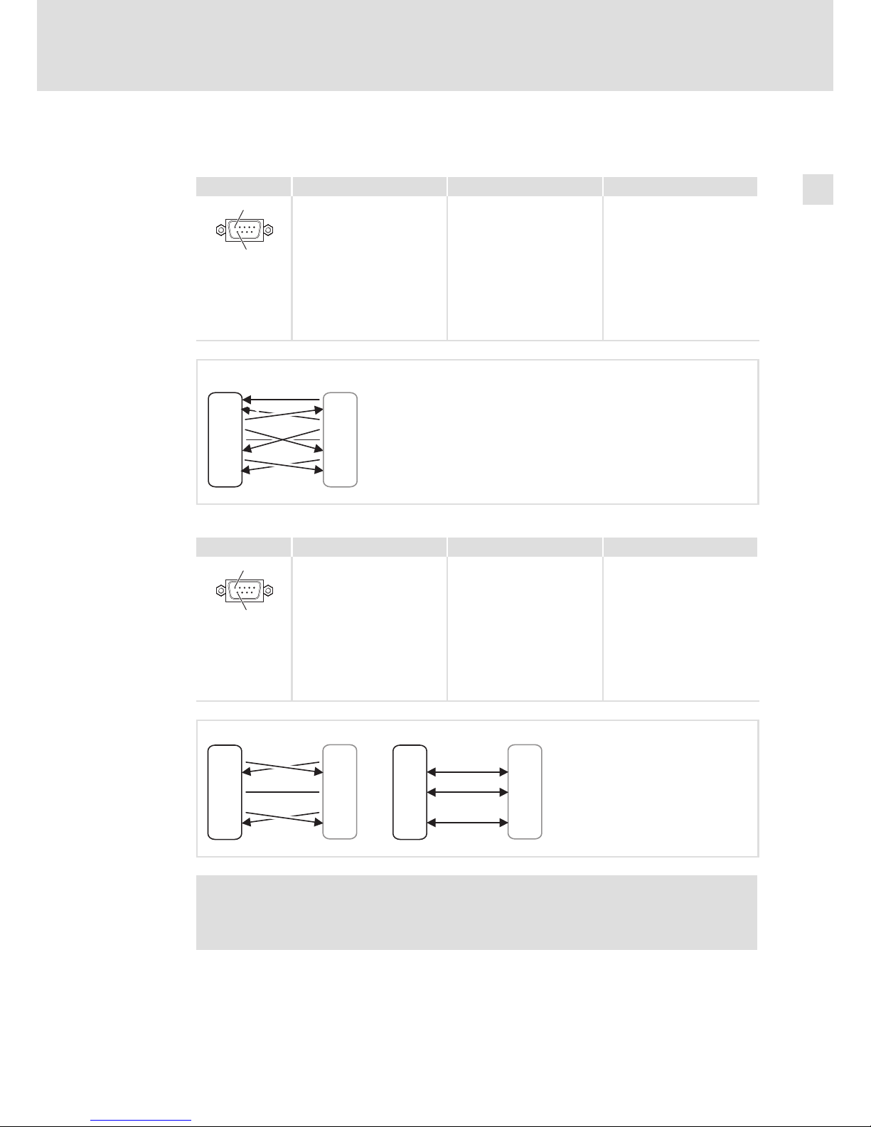
COM A (RS232):
Pin assignment Description Connection type Cable type
1
6
Pin 1: DCD
Pin 2: RXD
Pin 3: TXD
Pin 4: DTR
Pin 5: GND
Pin 6: DSR
Pin 7: RTS
Pin 8: CTS
Pin 9: RI
9−pole Sub−D plug Control cable
MC−CAN−003
1 DCD
2 RXD
3 TXD
4 DTR
5 GND
6 DSR
7 RTS
8 CTS
9 NC
1 DCD
2 RXD
3 TXD
4 DTR
5 GND
6 DSR
7 RTS
8 CTS
9 NC
COM A
RS232
xxx
MC−ISI_005
COM B (RS422/485):
Pin assignment Description Connection type Cable type
1
6
Pin 1: NC
Pin 2: TXD+
Pin 3: RXD+ (Data+)
Pin 4: NC
Pin 5: GND
Pin 6: NC
Pin 7: TXD−
Pin 8: RXD− (Data −)
Pin 9: NC
9−pole Sub−D plug Control cable
MC−CAN−003
1 NC
2 TXD+
3 RXD+
4 NC
5 GND
6 NC
7 TXD8 RXD9 NC
1 NC
2 TXD+
3 RXD+
4 NC
5 GND
6 NC
7 TXD8 RXD9 NC
RS422
(4-wire)
RS485
(2-wire)
COM B COM B
xxx xxx
1 NC
2 TXD+
3 RXD+
4 NC
5 GND
6 VCC
7 TXD8 RXD9 NC
1 NC
2 TXD+
3 RXD+
4 NC
5 GND
6 VCC
7 TXD8 RXD9 NC
MC−ISI_006
) Note!
The terminating resistor at the physically first and last node must be activated
(¶ 30).
Page 32

Electrical installation
Wiring and Configuration
MC−ISI
4
l
32
BA_MC−Card EN 1.0
Use of the MC card in Windowsâ XP or Windowsâ Embedded Standard 2009
In order to use the communication card in Windowsâ XP, a device driver is required.
Usually, the communication card in the IPC is already mounted and the driver is installed
and configured. Thus, an installation is only required if the communication card has been
ordered separately or the system is to be set up anew.
The device driver can be found on the "PC based Automation" DVD or on the Internet at
www.Lenze.com in the download area.
) Note!
The communication card is configured via jumper and DIP switch. The driver
cannot be used for this purpose.
) Note!
Addressing the communication card from your own applications requires
special programming skills. Lenze does not offer any support regarding this
matter. However, we can refer you to service providers who execute
customised programming and are familiar with Lenze Industrial PCs.
Use of the MC card in Windowsâ CE
In Windowsâ CE the card interact via control system. All required drivers are installed
) Note!
No special support is provided currently if you use the communication card in
your own applications. For special projects, please contact your sales office.
Page 33
Electrical installation
Wiring and Configuration
MC−PBM, MC−PBS
4
l
33
BA_MC−Card EN 1.0
4.3.4 MC−PBM, MC−PBS
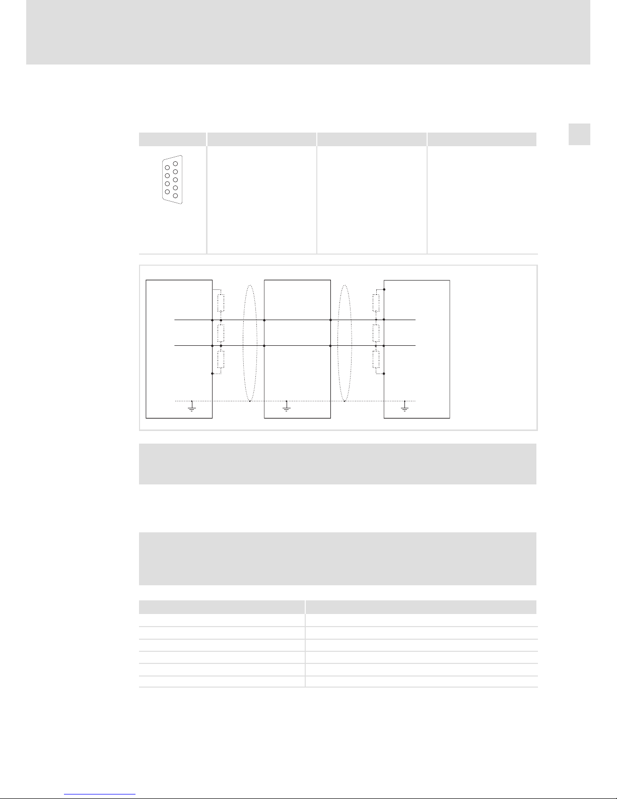
Wiring
Pin assignment Description Connection type Cable type
1
2
3
4
5
6
7
8
9
PROFIBUS connection
Pin 1: not assigned
Pin 2: not assigned
Pin 3: RxD/TxD−P(B)
Pin 4: RTS
Pin 5: M5V
Pin 6: P5V
Pin 7: not assigned
Pin 8: RxD/TxD−N(A)
Pin 9: not assigned
9−pole Sub−D socket See following table
epm−t223
RxD/TxD-P(B)
Schirm
Master
Slave
3
8
3
8
Schirm
P5V
P5V
M5VM5V
330W 330W
330W 330W
220W 220W
Schirm
3
8
RxD/TxD-N(A)
5
6
RxD/TxD-P(B)
RxD/TxD-N(A)
Slave
RxD/TxD-P(B)
RxD/TxD-N(A)
5
3
8
6
SLIO090
) Note!
The PROFIBUS cable must be terminated with its surge impedance.
Specification of the transmission cable
) Note!
Only use cables complying with the listed specifications of the PROFIBUS user
organisation.
Field Values
Specific resistance 135 ... 165 W/km, (f = 3 ... 20 MHz)
Capacitance per unit length £ 30 nF/km
Loop resistance < 110 W/km
Core diameter > 0.64 mm
Core cross−section > 0.34 mm
2
Cores Twisted double, insulated and shielded
Page 34

Electrical installation
Wiring and Configuration
MC−PBM, MC−PBS
4
l
34
BA_MC−Card EN 1.0
Baud rate / length of bus cable
Baud rate [kBit/s] Length [m]
9.6 − 93.75 1200
187.5 1000
500 400
1500 200
3000 − 12000 100
Use of the MC card in Windowsâ XP or Windowsâ Embedded Standard 2009
In order to use the communication card in Windowsâ XP, a device driver is required.
The device driver assumes the entire management of the interface and contains a simple
C interface which is addressed via a DLL. The user is only responsible for the transfer of the
correct parameters to the device driver. All dependencies on the operating system like
interrupt management and time monitoring are executed by the driver.
The driver comprises all functions for initialising, parameter setting, exchanging data, and
reading out status information. It operates in the polling or interrupt mode and controls
maximally two cards in an IPC.
Together with the device drivers, example programs are supplied in the source code for a
quick training. Other components are an installation program for registration at the
operating system and the SyCon.net bus configurator of the master.
) Note!
The communication card is based on the netX technology of the Hilscher
company (¶ 44). Further information on the programming interface and
programming examples for the CIF Device Driver can be obtained from the
Hilscher company.
Only drivers approved by Lenze may be used.
Addressing the communication card from your own applications requires
special programming skills. Lenze can only assist you in the basic
commissioning of the card. If you have special questions about programming,
the Hilscher company will help you after contacting Lenze. There, also
chargeable services can be ordered.
Usually, the communication card in the IPC is already mounted and the driver is installed
and configured. Thus, the following steps are only required if the communication card has
been ordered separately or the system is to be set up anew.
The "cifX Device Driver" and the corresponding documentation can be found on the "PC
based Automation" DVD or on the Internet at www.Lenze.com in the download area.
Page 35

Electrical installation
Wiring and Configuration
MC−PBM, MC−PBS
4
l
35
BA_MC−Card EN 1.0
X How to install the device driver:
1. Switch on the IPC after installing the communication card.
The operating system recognises the new hardware and the "Found New Hardware
Wizard" starts.
2. Select Install from a list or specific location.
3. Insert the "PC based Automation" DVD into the DVD drive and click Next.
4. Select the Search the best driver in these locations option field and the Search
exchangeable disk storage (floppy disk, CD,..) control field in the following dialog.
5. Click Next.
The CifX driver is installed. The installation progress is displayed. At the end, the wizard
reports that the software for the "cifX PCI/PCIe Device" has been installed.
6. Click Complete.
7. Check if the communication card has been installed correctly:
– Start the Windows
â
system control.
– If you have set the "classic view", double−click the System entry. If you have set the
"category view", select Performance and Maintenance W System.
– Select the Hardware register from the "System properties" dialog.
The device manager is opened. If no error is reported under "CIFx Communication
Interface" W "CifX PCI/PCIe Device", the communication card has been installed
correctly.
Page 36
Electrical installation
Wiring and Configuration
MC−PBM, MC−PBS
4
l
36
BA_MC−Card EN 1.0
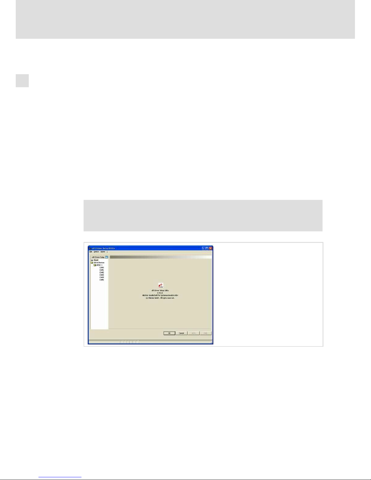
X How to configure the device driver:
1. Start the "cifX Driver Setup Utility":
– Open the Windows
â
system control.
– If you have set the "classic view", double−click the cifx Setup entry. If you have set
the "category view", first select Other Control Panel Options in the left window
area and then double−click the cifx Setup entry.
I Tip!
If, in an exceptional case, the device driver is to be installed before the
communication card has been installed, start the "cifX Driver Setup Utility" via
the Windows Explorer. For this purpose, go to the x:\Programs\cifX Device
Driver folder and double−click cifX Setup.exe.
After the application has started, its user interface is displayed. Use the object tree in
the left window area to open the corresponding dialog pages in which you assign a
firmware file to the communication card.
) Note!
The navigation pane can be shown and hidden via the Hide navigation pane /
Show navigation pane icon.
2. Assign the bus−specific firmware file to the communication channel 0 (CH#0):
– Go to the object tree and open the Active Devices folder and the (sub) folder of the
communication card (e.g. cifX0 ( )) you want to configure.
– Click the communication channel you want to assign to a firmware file. The
respective dialog page is displayed.
– Go to the Downloads (Modules) area, click the Add button and select the firmware
file (*.nxf) in the following menu.
– Confirm the selection with OK. The file path and the name of the firmware file are
displayed in the "File" list.
– Click the Apply button.
Page 37

Electrical installation
Wiring and Configuration
MC−PBM, MC−PBS
4
l
37
BA_MC−Card EN 1.0
3. Exit the "cifX Driver Setup Utility" application via the File W Quit menu.
) Note!
Only for MC−PBM (Master):
ƒ Configure the bus via the host application or the bus configurator
"SyCon.net".
Only for MC−PBS (Slave):
ƒ Configure the bus via the warm start parameters in the "cifX Driver Setup
Utility". Further information can be obtained from the online help of the
"cifX Driver Setup Utility" and the documentation of Hilscher.
Use of the MC card in Windowsâ CE
A) IPCs
The following conditions must be met for operating the card:
1. There must be a "Config" folder on the CF card in the storage drive.
2. This folder must contain a firmware file named "Firmware.nxt".
3. The card must be configured:
– MC−PBS (MPI): Configuration via an end application.
– MC−PBM: There must be a "Config.dbm" file in the "Config" folder. Further
information on this can be found in the documentation for your FDT frame
application.
At the next system start, the driver loads the firmware and the configuration from the
"Config" folder to the communication card.
) Note!
No special support is provided currently if you use the communication card in
your own applications. For special projects, please contact your sales office.
B) Controller
In Windows
â
CE the card interact via control system. All required drivers are installed
) Note!
No special support is provided currently if you use the communication card in
your own applications. For special projects, please contact your sales office.
Page 38
Electrical installation
Wiring and Configuration
MC−PNC, MC−PND
4
l
38
BA_MC−Card EN 1.0
4.3.5 MC−PNC, MC−PND
Wiring
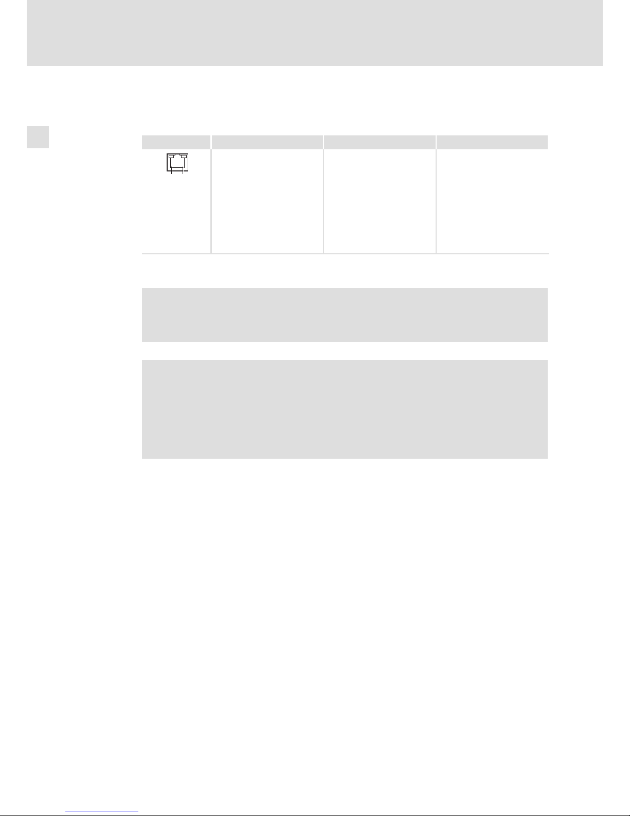
Description Connection type Cable type
18
Ethernet connection
Pin 1: TX+
Pin 2: TX−
Pin 3: RX+
Pin 4: Term1*
Pin 5: Term1*
Pin 6: RX−
Pin 7: Term2**
Pin 8: Term2**
RJ45 socket
Network cable CAT5 S/UTP or
CAT5e S/FTP (recommended),
cable length max. 100 m
MC−PNx−003
* Bridged and terminated by RC circuit against PE
** Bridged and terminated by RC circuit against PE
) Note!
The device supports the auto−crossover function where RX and TX can be
exchanged, if required.
) Note!
If the RJ45 plug connection is exposed to oscillating or vibrating stress:
ƒ Use a strain relief in the immediate vicinity of the RJ45 socket.
ƒ Select the contact surface on which the device is mounted as fixing point of
the strain relief.
ƒ Comply with the related minimum bending radius of the cable used.
Page 39

Electrical installation
Wiring and Configuration
MC−PNC, MC−PND
4
l
39
BA_MC−Card EN 1.0
Use of the MC card in Windowsâ XP or Windowsâ Embedded Standard 2009
In order to use the communication card in Windowsâ XP, a device driver is required.
The device driver assumes the entire management of the interface and contains a simple
C interface which is addressed via a DLL. The user is only responsible for the transfer of the
correct parameters to the device driver. All dependencies on the operating system like
interrupt management and time monitoring are executed by the driver.
The driver comprises all functions for initialising, parameter setting, exchanging data, and
reading out status information. It operates in the polling or interrupt mode and controls
maximally two cards in an IPC.
Together with the device drivers, example programs are supplied in the source code for a
quick training. Other components are an installation program for registration at the
operating system and the SyCon.net bus configurator of the master.
) Note!
The communication card is based on the netX technology of the Hilscher
company (¶ 44). Further information on the programming interface and
programming examples for the CIF Device Driver can be obtained from the
Hilscher company.
Only drivers approved by Lenze may be used.
Addressing the communication card from your own applications requires
special programming skills. Lenze can only assist you in the basic
commissioning of the card. If you have special questions about programming,
the Hilscher company will help you after contacting Lenze. There, also
chargeable services can be ordered.
Usually, the communication card in the IPC is already mounted and the driver is installed
and configured. Thus, the following steps are only required if the communication card has
been ordered separately or the system is to be set up anew.
The "cifX Device Driver" and the corresponding documentation can be found on the "PC
based Automation" DVD or on the Internet at www.Lenze.com in the download area.
Page 40

Electrical installation
Wiring and Configuration
MC−PNC, MC−PND
4
l
40
BA_MC−Card EN 1.0
X How to install the device driver:
1. Switch on the IPC after installing the communication card.
The operating system recognises the new hardware and the "Found New Hardware
Wizard" starts.
2. Select Install from a list or specific location.
3. Insert the "PC based Automation" DVD into the DVD drive and click Next.
4. Select the Search the best driver in these locations option field and the Search
exchangeable disk storage (floppy disk, CD,..) control field in the following dialog.
5. Click Next.
The CifX driver is installed. The installation progress is displayed. At the end, the wizard
reports that the software for the "cifX PCI/PCIe Device" has been installed.
6. Click Complete.
7. Check if the communication card has been installed correctly:
– Start the Windows
â
system control.
– If you have set the "classic view", double−click the System entry. If you have set the
"category view", select Performance and Maintenance W System.
– Select the Hardware register from the "System properties" dialog.
The device manager is opened. If no error is reported under "CIFx Communication
Interface" W "CifX PCI/PCIe Device", the communication card has been installed
correctly.
Page 41
Electrical installation
Wiring and Configuration
MC−PNC, MC−PND
4
l
41
BA_MC−Card EN 1.0
X How to configure the device driver:
1. Start the "cifX Driver Setup Utility":
– Open the Windows
â
system control.
– If you have set the "classic view", double−click the cifx Setup entry. If you have set
the "category view", first select Other Control Panel Options in the left window
area and then double−click the cifx Setup entry.
I Tip!
If, in an exceptional case, the device driver is to be installed before the
communication card has been installed, start the "cifX Driver Setup Utility" via
the Windows Explorer. For this purpose, go to the x:\Programs\cifX Device
Driver folder and double−click cifX Setup.exe.
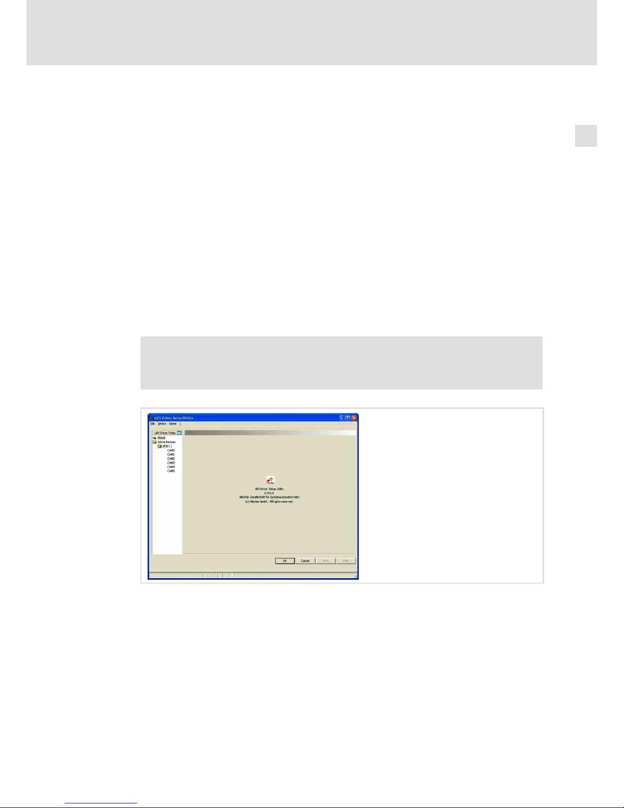
After the application has started, its user interface is displayed. Use the object tree in
the left window area to open the corresponding dialog pages in which you assign a
firmware file to the communication card.
) Note!
The navigation pane can be shown and hidden via the Hide navigation pane /
Show navigation pane icon.
2. Assign the bus−specific firmware file to the communication channel 0 (CH#0):
– Go to the object tree and open the Active Devices folder and the (sub) folder of the
communication card (e.g. cifX0 ( )) you want to configure.
– Click the communication channel you want to assign to a firmware file. The
respective dialog page is displayed.
– Go to the Downloads (Modules) area, click the Add button and select the firmware
file (*.nxf) in the following menu.
– Confirm the selection with OK. The file path and the name of the firmware file are
displayed in the "File" list.
– Click the Apply button.
Page 42

Electrical installation
Wiring and Configuration
MC−PNC, MC−PND
4
l
42
BA_MC−Card EN 1.0
3. Exit the "cifX Driver Setup Utility" application via the File W Quit menu.
) Note!
Only for MC−PNC (Controller):
ƒ Configure the bus via the host application or the bus configurator
"SyCon.net".
Only for MC−PND (Device):
ƒ Configure the bus via the warm start parameters in the "cifX Driver Setup
Utility". Further information can be obtained from the online help of the
"cifX Driver Setup Utility" and the documentation of Hilscher.
Use of the MC card in Windowsâ CE
A) IPCs
The following conditions must be met for operating the card:
1. There must be a "Config" folder on the CF card in the storage drive.
2. This folder must contain a firmware file named "Firmware.nxt".
3. The card must be configured:
– MC−PBS (MPI): Configuration via an end application.
– MC−PBM: There must be a "Config.dbm" file in the "Config" folder. Further
information on this can be found in the documentation for your FDT frame
application.
At the next system start, the driver loads the firmware and the configuration from the
"Config" folder to the communication card.
) Note!
No special support is provided currently if you use the communication card in
your own applications. For special projects, please contact your sales office.
B) Controller
At the time the Lenze controllers can only communicate with the MC−PND via control
system, not with the MC−PNC.
In Windows
â
CE the card interact via control system. All required drivers are installed
) Note!
No special support is provided currently if you use the communication card in
your own applications. For special projects, please contact your sales office.
Page 43
Appendix
Use of the PCAN view/PCAN Explorer with MC−CAN2
5
l
43
BA_MC−Card EN 1.0
5 Appendix
5.1 Use of the PCAN view/PCAN Explorer with MC−CAN2
Peak System Technik GmbH provides the PCAN Explorer software for the diagnostics of a
CAN network. The PCAN view program is the basic free−of−charge version of this program.
When using these programs with the MC−CAN2 card, please observe the following:
ƒ In the PCAN software, the MC−CAN2 card is not represented as hardware but as
client of a network. For this reason, the networks in the PCAN software are
represented as "internal networks" as if these networks would have no connection
to a hardware.
ƒ The status bar of the PCAN Explorer indicates a symbol with a crossed out hardware
even with a correct connection. Information such as "Busheavy" is not displayed in
the status bar.
ƒ The PCAN view shows information such as "Busheavy" only for one second, then it
disappears again.
The network names are defined as follows:
Expansion slot Connection Network name
MC 1 CAN 1 LSysbusNet1
MC 1 CAN 2 LSysbusNet2
MC 2 CAN 1 LSysbusNet3
MC 2 CAN 2 LSysbusNet4
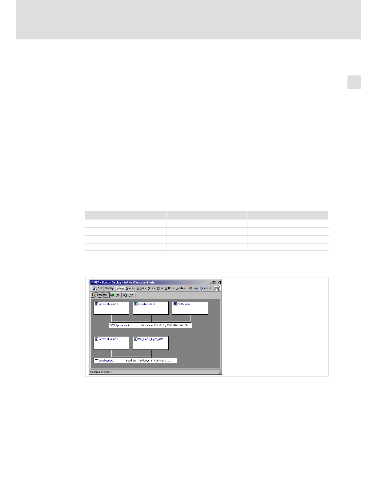
The following illustration shows how the MC−CAN2 and the connected networks are
represented in the PCAN stat diagnostic program.
The baud rate is exclusively selected via the system bus configurator, not via network
names.
The windows "Receive" and Transmit" now continuously show the telegrams.
Details of the PCAN view, PCAN stat and PCAN Explorer programs can be found in the
corresponding online helps.
Page 44

Appendix
Contact data of system partners
5
l
44
BA_MC−Card EN 1.0
5.2 Contact data of system partners
Hilscher
Hilscher Gesellschaft für Systemautomation mbH
Rheinstraße 15
D−65795 Hattersheim
+49 6190 / 9907−0
www.hilscher.com
Peak
Peak System Technik GmbH
Otto−Röhm−Str. 69
D−64293 Darmstadt
+49 6151 / 8173−0
www.peak−system.com
Page 45

Appendix
Contact data of system partners
5
l
45
BA_MC−Card EN 1.0
Page 46

Q
© 11/2013
F
Lenze Automation GmbH
Hans−Lenze−Str. 1
D−31855 Aerzen
Germany
Service Lenze Service GmbH
Breslauer Straße 3
D−32699 Extertal
Germany
(
+49(0)51 54 /82−0
(
008000/ 2446877 (24 h helpline)
Ê
+49(0)51 54 /82 − 28 00
Ê
+49(0)5154/ 82−11 12
ü
www.Lenze.com
BA_MC−Card § .N*{ § EN § 1.0 § TD29
10987654321
 Loading...