

Page 1
MC3000 Series Drives
Metasys N2 Communications Guide
Page 2

About These Instructions
This documentation applies to the use of an MC3000 Series Variable Frequency Drive with Metasys N2 protocol and
should be used in conjunction with the MC3000 Series Installation and Operation Manual (Document M301) that
shipped with the drive. These documents should be read in their entirety as they contain important technical data
and describe the installation and operation of the drive.
Metasys® is a registered trademark of Johnson Controls, Inc., http://www.johnsoncontrols.com
© 2003 Lenze AC Tech Corporation
No part of this documentation may be copied or made available to third parties without the explicit written approval
of Lenze AC Tech Corporation. All information given in this documentation has been carefully selected and tested
for compliance with the hardware and software described. Nevertheless, discrepancies cannot be ruled out. Lenze
AC Tech does not accept any responsibility nor liability for damages that may occur. Any necessary corrections will
be implemented in subsequent editions.
Page 3

Contents
1 Safety Information .............................................................................................................1
1.1 Warnings, Cautions and Notes ..............................................................................1
1.1.1 General ....................................................................................................1
1.1.2 Application ...............................................................................................1
1.1.3 Installation ...............................................................................................1
1.1.4 Electrical Connection ................................................................................2
1.1.5 Operation .................................................................................................2
2 Introduction .......................................................................................................................3
2.1 Metasys N2 Communications ................................................................................3
2.2 Serial Communications Wiring ..............................................................................3
3 Drive Setup and Programming ...........................................................................................4
3.1 Serial Communication Setup .................................................................................4
3.2 Communication Overrides .....................................................................................5
4 MC3000 N2 Points ............................................................................................................6
4.1 Metasys N2 Point Map ..........................................................................................7
4.2 Analog Input (AI) Point Descriptions .......................................................................8
4.3 Binary Input (BI) Point Descriptions .......................................................................11
4.4 Analog Output (AO) Point Descriptions ...................................................................11
4.5 Binary Output (BO) Point Descriptions ...................................................................13
4.6 Reference and Links .............................................................................................13
i RG-MCMET
Page 4

1 Safety Information
1.1 Warnings, Cautions and Notes
1.1.1 General
Some parts of Lenze controllers (frequency inverters, servo inverters, DC controllers) can be live, moving
and rotating. Some surfaces can be hot.
Non-authorized removal of the required cover, inappropriate use, and incorrect installation or operation
creates the risk of severe injury to personnel or damage to equipment.
All operations concerning transport, installation, and commissioning as well as maintenance must be
carried out by qualified, skilled personnel (IEC 364 and CENELEC HD 384 or DIN VDE 0100 and IEC report
664 or DIN VDE0110 and national regulations for the prevention of accidents must be observed).
According to this basic safety information, qualified skilled personnel are persons who are familiar with
the installation, assembly, commissioning, and operation of the product and who have the qualifications
necessary for their occupation.
1.1.2 Application
Safety Information
Drive controllers are components designed for installation in electrical systems or machinery. They are
not to be used as appliances. They are intended exclusively for professional and commercial purposes
according to EN 61000-3-2. The documentation includes information on compliance with EN 61000-3-2.
When installing the drive controllers in machines, commissioning (i.e. the starting of operation as directed)
is prohibited until it is proven that the machine complies with the regulations of the EC Directive 98/37/EC
(Machinery Directive); EN 60204 must be observed.
Commissioning (i.e. starting drive as directed) is only allowed when there is compliance to the EMC Directive
(89/336/EEC).
The drive controllers meet the requirements of the Low Voltage Directive 73/23/EEC. The harmonised
standards of the series EN 50178/DIN VDE 0160 apply to the controllers.
The availability of controllers is restricted according to EN 61800-3. These products can cause
radio interference in residential areas. In the case of radio interference, special measures may be
necessary for drive controllers.
1.1.3 Installation
Ensure proper handling and avoid excessive mechanical stress. Do not bend any components and do not
change any insulation distances during transport or handling. Do not touch any electronic components
and contacts. Controllers contain electrostatically sensitive components, which can easily be damaged by
inappropriate handling. Do not damage or destroy any electrical components since this might endanger
your health! When installing the drive ensure optimal airflow by observing all clearance distances in the
drive's user manual. Do not expose the drive to excessive: vibration, temperature, humidity, sunlight, dust,
pollutants, corrosive chemicals or other hazardous environments.
1 RG-MCMET
Page 5

Safety Information
1.1.4 Electrical Connection
When working on live drive controllers, applicable national regulations for the prevention of accidents (e.g.
VBG 4) must be observed.
The electrical installation must be carried out in accordance with the appropriate regulations (e.g.
cable cross-sections, fuses, PE connection). Additional information can be obtained from the regulatory
documentation.
The regulatory documentation contains information about installation in compliance with EMC (shielding,
grounding, filters and cables). These notes must also be observed for CE-marked controllers.
The manufacturer of the system or machine is responsible for compliance with the required limit values
demanded by EMC legislation.
1.1.5 Operation
Systems including controllers must be equipped with additional monitoring and protection devices according
to the corresponding standards (e.g. technical equipment, regulations for prevention of accidents, etc.).
You are allowed to adapt the controller to your application as described in the documentation.
DANGER!
• After the controller has been disconnected from the supply voltage, do not touch the live
components and power connection until the capacitors have discharged. Please observe the
corresponding notes on the controller.
• Do not continuously cycle input power to the controller more than once every three minutes.
• Close all protective covers and doors during operation.
WARNING!
Network control permits automatic starting and stopping of the inverter drive. The system design
must incorporate adequate protection to prevent personnel from accessing moving equipment
while power is applied to the drive system.
Table 1: Pictographs used in these instructions
Pictograph Signal word Meaning Consequences if ignored
DANGER!
WARNING!
STOP!
NOTE
Warning of Hazardous Electrical
Voltage.
Impending or possible danger
for persons
Possible damage to equipment Damage to drive system or its surroundings
Useful tip: If observed, it will
make using the drive easier
Reference to an imminent danger that may
result in death or serious personal injury if the
corresponding measures are not taken.
Death or injury
RG-MCMET 2
Page 6
2 Introduction
This document will explain how to operate a Lenze-AC Tech MC3000 Variable Frequency Drive using
Metasys N2 protocol. It is intended as a serial communications supplement only and will not discuss
normal drive operations. For more information regarding normal drive setup and functionality, refer to the
MC3000 Installation and Operation Manual (M301).
2.1 Metasys N2 Communications
MC3000 drives running N2 protocol act as N2 devices on a Metasys® Network and function as slaves only.
Thus the device communicating with an MC3000 drive must be an N2 master. The communication rate is
9600 bps with 8 data bits, no parity, 1 start bit and 1 stop bit. The bit sequence is as follows:
START 1 2 3 4 5 6 7 8 STOP
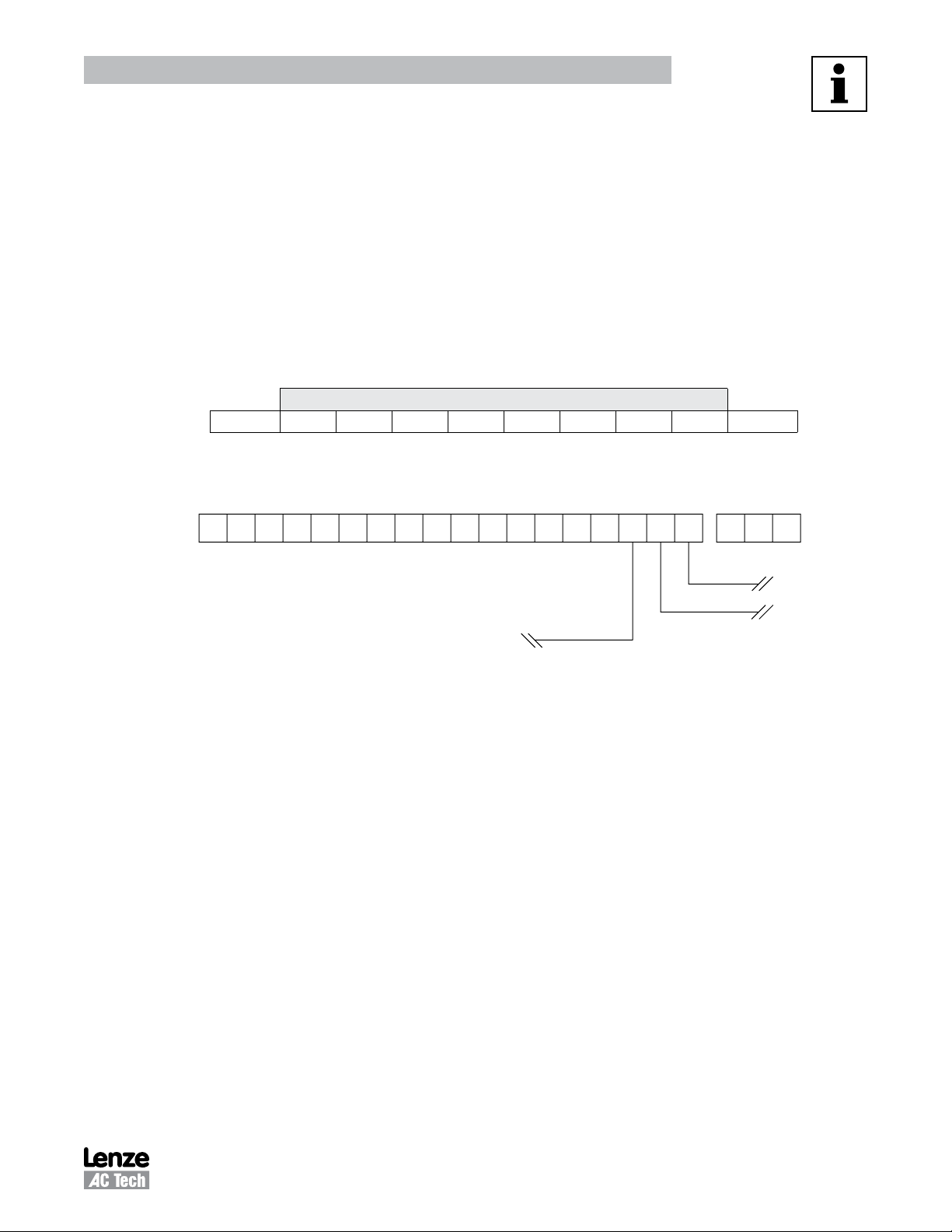
2.2 Serial Communications Wiring
Figure 1 illustrates the MC3000 Series Terminal Strip and connections for the N2 Metasys network.
21 5A 5B 6 10A 10B 2 13A12A 13B 13C 13D 14 15 2 TXBRXA 16 17 18
Introduction
DATA
N2
Reference
Figure 1: MC3000 Terminal Strip
The N2+ terminal is connected to MC3000 drive terminal RXA.
The N2- terminal is connected to MC3000 drive terminal TXB.
The N2 Reference is connected to MC3000 drive terminal 2.
N2+
N2-
3 RG-MCMET
Page 7

Drive Setup & Programming
3 Drive Setup and Programming
Most drive parameters (including those required for serial communications) are not accessible through the
N2 Network. They can only be accessed by entering the Programming Mode of the drive itself. Refer to the
MC3000 Installation and Operation Manual (M301) for more information.
When in Programming Mode, the drive will not accept any write, memorize or characterize commands from
the N2 Network. This is necessary to prevent conflicts between the two modes of parameter modification.
3.1 Serial Communication Setup
The factory default values for all drive parameters are setup to allow immediate serial communications
(without serial start and serial speed/setpoint commands). For serial speed/setpoint and/or serial start
control, modify the setting of Drive Parameter #30 (Control). The drive parameters that are required for
serial communications, including Drive Parameter #30, are described below.
30 CONTROL should be set to accommodate the specific application intent. The action of a
Watchdog timeout depends on the setting of the CONTROL parameter. If the
CONTROL parameter is set for:
− LOCAL : the drive will stop when a serial timeout occurs.
− KEYPAD 2 (LOCAL contol without the need for TB-1 to run): the drive will stop
when a serial timeout occurs.
− REMOTE: serial timeout will not work since the drive cannot be unlocked in
REMOTE mode.
MC3000 drives STOP when a serial timeout occurs. There is no fault for this. Any
time CONTROL is changed from LOCAL to REMOTE the drive STOPS immediately.
The Control Parameter on MC drives (Programming Parameter #30 / AC Tech Register #81) determines
how much control a user has over a drive via the serial link. The Control Parameter must be appropriately
programmed for a particular application. Refer to the MC Series Installation and Operation Manual (M301)
for a detailed explanation on programming the drive parameters.
Table 2: Control (Parameter #30)
MC3000
Setting Description
00 LOCAL (default)
01 REMOTE
02 SERIAL
03 KEYPAD
04 TB STRIP
05 KEYPAD 2
All control options are subject to the Parameter and Control Locking/Unlocking procedures.
RG-MCMET 4
Page 8

Drive Setup & Programming
57 SERIAL Must be set to WITH TIMER (default) or W/O TIMER for the drive to communicate
with the N2 Network. Serial communications will not work if this parameter is set
to DISABLED. The timeout period is fixed at a value of 30 seconds.
58 SERIAL ADDRESS This point contains the address of the N2 Network device. It is adjustable from
1−255. The default address (30) is intended for configuration purposes only.
3.2 Communication Overrides
Overrides are also released under the following circumstances:
• Drive Parameter #57 (Serial) is set to DISABLED.
• Drive Parameter #58 (Serial Address) is changed.
• Drive Parameter #30 (Control) is changed.
• Drive Parameter #65 (Program) is changed to RESET 60 or REST 50 (i.e., a factory reset is
performed) and Drive Parameter #58 (Serial Address) was not previously set to 30. In this case,
serial communications will be terminated immediately.
• Drive Parameter #65 (Program) is changed to RESET 60 or REST 50 (i.e., a factory reset is
performed) and Drive Parameter #30 (Control) was not previously set to NORMAL.
NOTE - Drive Stop unrelated to Serial Communication
The drive will also be brought to a stop if changed from LOCAL to REMOTE or from REMOTE to LOCAL.
5 RG-MCMET
Page 9

N2 Points
4 MC3000 N2 Points
The entries in Table 3 are based upon MC3000 Drive Software Version 213-043 Revision 05 (Parameter
Version 143). If a later revision of software changed parameter definitions or added parameters it could
seriously affect the drive’s operation. This will be identified for a given drive by examining Analog Input
Point 1 (Parameter Version). If it is not 143, writing to any register on the drive MUST NOT BE ATTEMPTED
unless your Controller has been setup to support the new configuration.
NOTE
The Change of State (COS) feature as a means of alarm/warning notification on MC3000
Series Drives has not been implemeted. Upon being polled, the Analog Input points
that can change value will report that a change of state (COS) has occurred. However,
since the alarm limits that have been specified are ignored, the alarm and warning flags
will never be set. As this feature is not implemented, normal Metasys Alarm/Warning
Notification will be defeated. This is generally NOT an issue since none of the Analog
Input Points require alarm limits in standard operation.
If, for some reason, notification for alarms and warnings is required, it will be necessary for the operator
to perform the following:
• Map the specific object requiring COS to a CS object.
• Define an AD or BD object with the CS object of the required COS point as the “Associated In”.
• Assign Alarm Limits to the AD object.
• The AD or BD point will only be scanned at a minimum of 30 seconds
• The normal state of the BO must be updated (written to) by GPL.
Analog/Binary Input points that are mapped in directly that do not support COS will never report a change
of state condition. They will report the current value when read but no alarm notification will occur. A read
will only occur if a focus window is open or a feature requires the current value.
The MC3000 N2 Points are divided into four types: analog input, binary input, analog output and binary
output. Sections 4.2 through 4.5 describe each of these point types and the individual point numbers within
each.
RG-MCMET 6
Page 10

4.1 Metasys N2 Point Map
Table 3: Metasys N2 Point Map for MC3000 Series Drives
Point
Point
1
Type
#
1 1 Parameter Version R -- 0 -- -- 143
1 2 Software Version R -- 0 -- -- 043
1 3 Software Revision R -- 0 -- -- 05
1 4 Drive Config/Size R -- 0 0 57 --
1 5 Drive Class R -- 0 -- -- 65
1 6 Total Runtime (RUNTIME HRS) R hrs 0 0 --
1 7 Total Runtime (RUNTIME MIN) R min 0 0 --
1 8 Operational Status (RUN STATUS) R -- 0 0 10 --
1 9 Load Percent (LOAD PERCENT) R % 0 150 180 180
1 10 Motor Voltage (MOTOR VOLTS) R VAC 0
1 11 Present Fault (FAULT) R -- 0 0 23 0
1 12 Recorded Fault 1 R -- 0 0 23 0
1 13 Recorded Fault 2 R -- 0 0 23 0
1 14 Recorded Fault 3 R -- 0 0 23 0
1 15 Recorded Fault 4 R -- 0 0 23 0
1 16 Recorded Fault 5 R -- 0 0 23 0
1 17 Recorded Fault 6 R -- 0 0 23 0
1 18 Recorded Fault 7 R -- 0 0 23 0
1 19 Recorded Fault 8 R -- 0 0 23 0
1 20 PID Feedback (PID FEEDBACK) R PID 0 Note 3 Note 3 Note 3
1 21 PID Setpoint Command (PID SETPOINT) R PID 0 Note 3 Note 3 Note 3
1 22 Actual Speed (ACTUAL FREQ) R Hz 2 0 12000 --
2 01 Fault Condition (OK.FAULT) R -- 0 OK FLT OK
3 01 Command Speed (COMMAND SPD) R/O Hz 2 0 120.00 20.00
3 02 Keypad Command Speed (CMD KEY SPD) R/O Hz 2 0 120.00 20.00
3 03 Normal Acceleration (ACCEL) R/O sec 1 * 3600.0 30.0
3 04 Normal Deceleration (DECEL) R/O sec 1 * 3600.0 30.0
3 05 Local PID Command R/O PID 0 Note 3 Note 3 Note 3
3 06 Control Mode R/O -- 0
4 01 History R/O -- 0 0 (maintain) 1 (clear) 0
4 02 Start/Stop Drive (CMD RUN.STOP) R/O -- 0 0 (stop) 1 (start) 0
4 03 Speed Control Auto/Manual R/O -- 0 0 (auto) 1 (manual) 0
4 04 Clear Present Fault (CLEAR FAULT) R/O -- 0 0 1 (clear)
Description (Point Name) Read (R)/
Override (R/O)
N2 Points
Point
Units
Decimal
Places
MIN
Value
MAX
Value
Default
Value
2
2
2
NOTES:
1. Point Types: 1 = Analog Input; 2 = Binary Input; 3 = Analog Output; 4 = Binary Output
2. Current Value of the parameter version, software version and software revision.
3. Units, MIN/MAX Values: for this point are defined via Drive Parameters #31, 75 and 76 respectively.
Refer to notes in sections 4.2 and 4.4.
* Refer to MC3000 Installation & Operation Manual (M301)
7 RG-MCMET
Page 11

N2 Points
4.2 Analog Input (AI) Point Descriptions
Point Description
1-01: Parameter Version
The entries in Table 1 are based upon Parameter Version = 143. If a later revision of
software changed parameter definitions or added parameters it could seriously affect the
drive’s operation. This will be identified for a given drive by examining Analog Input Point
1 (1-01) Parameter Version. If it is not 143, writing to any register on the drive MUST NOT
BE ATTEMPTED unless your Controller has been setup to support the new configuration.
1-02: Software Version
This point represents the Software Version for MC3000 Metasys Software in the numerical
format "xxx-xxx". The current software version number is 213-043.
1-03: Software Revision
This point represents the drive’s software revision level in the numerical format "xx". The
current revision status is 05.
1-04: Drive Configuration
This point represents the drive size (Configuration) as listed in the following table:
Drive Config Horsepower Drive Voltage Drive Config Horsepower Drive Voltage
0 0.25 120 V 29 2.00 590/480 VAC
1 0.25 240/200 VAC 30 3.00 590/480 VAC
2 0.50 240/200 VAC 31 5.00 590/480 VAC
3 1.00 240/200 VAC 32 7.50 590/480 VAC
4 1.50 240/200 VAC 33 10.0 590/480 VAC
5 2.00 240/200 VAC 34 15.0 590/480 VAC
6 3.00 240/200 VAC 35 20.0 590/480 VAC
7 5.00 240/200 VAC 36 25.0 590/480 VAC
8 7.50 240/200 VAC 37 30.0 590/480 VAC
9 10.0 240/200 VAC 38 40.0 590/480 VAC
10 15.0 240/200 VAC 39 50.0 590/480 VAC
11 20.0 240/200 VAC 40 60.0 590/480 VAC
12 25.0 240/200 VAC 41 75.0 590/480 VAC
13 50.0 480/400 VAC 42 100.0 590/480 VAC
14 60.0 480/400 VAC 43 125.0 590/480 VAC
15 1.00 480/400 VAC 44 150.0 590/480 VAC
16 1.50 480/400 VAC 45 200.0 590/480 VAC
17 2.00 480/400 VAC 46 75.0 480/400 VAC
18 3.00 480/400 VAC 47 100.0 480/400 VAC
19 5.00 480/400 VAC 48 125.0 480/400 VAC
20 7.50 480/400 VAC 49 150.0 480/400 VAC
21 10.0 480/400 VAC 50 200.0 480/400 VAC
22 15.0 480/400 VAC 51 30.0 240/200 VAC
23 20.0 480/400 VAC 52 40.0 240/200 VAC
24 25.0 480/400 VAC 53 50.0 240/200 VAC
25 30.0 480/400 VAC 54 60.0 240/200 VAC
26 40.0 480/400 VAC 55 75.0 240/200 VAC
27 1.00 590/480 VAC 56 100.0 240/200 VAC
28 1.50 590/480 VAC 57 Unknown Unknown
RG-MCMET 8
Page 12

N2 Points
Point Description
1-05: Drive Class
This point represents the MC series drive class = 65 (41h).
1-06: Total Runtime Hours
This point represents the total accumulated time the drive has run in hours. This value can
be reset to 0 by entering the password 4425 and restoring factory defaults via parameter
65 (PROGRAM).
1-07: Total Runtime Minutes
This point represents the total accumulated time the drive has run in minutes. This
value can be reset to 0 by entering the password 4425 and restoring factory defaults via
parameter 65 (PROGRAM).
1-08: Operational Status
This point is for monitoring the actual operating condition of the drive. The value returned
is a number between 0 and 10 which corresponds to one of the following operating states:
Value Operational State Value Operational State
0 FAULT LOCKOUT 6 RUN
1 FAULT 7 ACCEL
2 START PENDING 8 DECEL
3 STOP 9 CURRENT LIMIT
4 DC BRAKE 10 DECEL OVERRIDE
5 RUN AT 0Hz
1-09: Load %
This point represents the drive load as a percentage of full load. The high limit for this point
is dictated by Parameter 1 (Current Limit). Depending on the setting of Parameter 0 (Line
Volts), the drive is capable of delivering 150% or 180% of its rated output current. This
value can be viewed on the local display by pressing the Enter key once.
1-10: Motor Voltage
This point represents the AC voltage that is currently being sent to the motor. This number
can be viewed on the local display by pressing the Enter key twice.
9 RG-MCMET
Page 13

N2 Points
Point Description
1-11: Present Fault
This point indicates the type of fault on which the drive is currently tripped. This point returns
a value between 0 and 23 which corresponds to one of the following fault conditions:
Value Fault Value Fault
0 NO FAULT 12 POWER SAG
1 OUTPUT FAULT 13 CONTROL FAULT
2 RESERVED 14 LANGUAGE
3 HIGH DC BUS VOLTS 15 EXTERNAL FAULT
4 HIGH DRIVE TEMPERATURE 16 INTERNAL16
5 THERMAL OVERLOAD 17 POWER TRANSIENT
6 RESERVED 18 S/W ERROR #1
7 LOW DC BUS VOLTS 19 S/W ERROR #2
8 RESERVED 20 S/W ERROR #3
9 DC BRAKE ERROR 21 S/W ERROR #4
10 FOLLOWER LOSS 22 S/W ERROR #5
11 DB ERROR 23 GENERAL S/W ERROR
1-12: Recorded Fault 1
This point represents the most recent fault condition that has occurred according to the
same code scheme as for the present fault object. To clear the fault history, refer to Point
4-01 (Clear Fault History)
1-13: Recorded Fault 2
This point represents the 2nd most recent fault condition that has occurred.
1-14: Recorded Fault 3
This point represents the 3rd most recent fault condition that has occurred.
1-15: Recorded Fault 4
This point represents the 4th most recent fault condition that has occurred.
1-16: Recorded Fault 5
This point represents the 5th most recent fault condition that has occurred.
1-17: Recorded Fault 6
This point represents the 6th most recent fault condition that has occurred.
1-18: Recorded Fault 7
This point represents the 7th most recent fault condition that has occurred.
1-19: Recorded Fault 8
This point represents the 8th most recent fault condition that has occurred.
RG-MCMET 10
Page 14

Point Description
1-20: PID Feedback
This point monitors the current state of the PID Feedback. If the drive is running in Local or
Serial Control Mode, the PID Setpoint will be as dictated by Local PID Cmd. If the drive is
running in Remote Control Mode, the Setpoint will come from either analog source TB-5A
or TB-5B. Refer to the MC3000 Installation and Operation Manual (M301) for more details
on PID functionality.
1-21: Command PID Setpoint
This point monitors the current state of the PID Setpoint. If the drive is running in Local or
Serial Control Mode, the PID Setpoint will be as dictated by Local PID Cmd. If the drive is
running in Remote Control Mode, the Setpoint will come from either analog source TB-5A
or TB-5B. Refer to the MC3000 Installation and Operation Manual (M301) for more details
on PID functionality.
1-22: Actual Speed
This point indicates the speed (in Hz) at which the drive is currently running.
4.3 Binary Input (BI) Point Descriptions
N2 Points
Point Description
2-01: Fault Condition
This point indicates whether or not the drive is currently tripped on a fault. This point
returns 0 (OK) if the drive is not in a fault condition or 1 (FAULT) if the drive is currently
faulted.
4.4 Analog Output (AO) Point Descriptions
Point Description
3-01: Command Speed
This point represents the speed at which the drive is being commanded to run. It is
acquired from the currently selected speed source (preset speeds, speed pot, etc. if set to
auto speed control; keypad if set for manual speed control). Overriding this parameter will
force the drive to operate at the override speed until released. Until the point is released,
the drive will ignore any changes in speed induced by the currently selected speed source.
The value of this point is limited by drive Parameters 10 (minimum frequency) and 11
(maximum frequency). Parameter 10 can be set down to 0.00 Hz. Parameter 11 can be set
up to 120.00 Hz.
3-02: Keypad Command Speed
This point represents the command speed as dictated by the keypad. This speed is only
used if the drive is set for MANUAL speed control. Therefore, overriding this parameter will
only have an effect if MANUAL speed control is selected. The value of this point is also
limited by Parameters 10 and 11.
11 RG-MCMET
Page 15

N2 Points
Point Description
3-03: Normal Acceleration
This point sets the time that it will take for the drive to ramp up the motor from 0.0Hz to the
value set in Parameter 18 (Base Frequency). The maximum value for this point is 3600.0
seconds. The minimum value is either 0.1 sec or 0.3 sec depending on the horsepower of
the drive. For the actual minimum boundary, refer to the MC3000 Installation and Operation
Manual (M301).
When this object is overridden, the override value is stored in a temporary variable and
not in the drive’s memory. If this parameter is viewed on the drive itself via program
mode while it is being overridden, the value that is displayed will not reflect the override
value but rather the value that was last stored into the drive’s memory via programming
mode. Example: if the initial value of Parameter 8 (ACCEL), is 30.0 seconds and this object
is overridden to be 15.0 seconds, the serial link will report the 15.0 second value and
the drive response will be based on the 15.0 second value but in programming mode,
Parameter 8 will still display the original value of 30.0 seconds.
3-04: Normal Deceleration
This point sets the time that it will take for the drive to ramp down the motor from the
value set in Parameter 18 (Base Frequency) to 0.0Hz. The maximum value for this point
is 3600.0 seconds. The minimum value is between 0.1 sec and 2.0 sec depending on the
voltage rating and horsepower of the drive as well as the presence of a dynamic brake.
For the actual minimum boundary, refer to the MC3000 Installation and Operation Manual
(M301).
The Normal Deceleration time is only used when Parameter 26 (Stop) is set to RAMP.
When this object is overridden, the override value is stored in a temporary variable and
not into the drive’s memory. If this parameter is viewed on the drive itself via program
mode while it is being overridden, the value that is displayed will not reflect the override
value but rather the value that was last stored into the drive’s memory via programming
mode. Example: if the initial value of Parameter 9 (DECEL) is 30.0 seconds and this object
is overridden to be 15.0 seconds, the serial link will report the 15.0 second value and
the drive response will be based on the 15.0 second value but in programming mode,
Parameter 9 will still display the original value of 30.0 seconds.
3-05: Local PID Command
This point indicates the PID Setpoint that is used when the drive is running in LOCAL or
SERIAL modes. The PID Setpoint is the number that the drive is attempting to match with
the PID Feedback value. Refer to the MC3000 Installation and Operation Manual (M301)
for more details on PID functionality.
RG-MCMET 12
Page 16

Point Description
3-06: Control Mode
This point allows the user to manipulate the control mode in which the drive is running. The
drive powers up and will remain in LOCAL Control Mode until the first override or release
command is sent to it. The drive will then switch to SERIAL Control Mode. This point can be
used to change the control mode back to LOCAL (0) for front panel manipulation. It can also
be used to change the control mode to REMOTE to control the drive from the terminal strip.
If this point is overridden with REMOTE (1), no overrides or releases will be recognized
except for the CONTROL MODE point until the drive is returned to SERIAL control mode. The
release of this parameter will return it to the value specified by Parameter 30 (CONTROL).
4.5 Binary Output (BO) Point Descriptions
Point Description
4-01: Clear Fault History
This history stores the last eight (8) faults that tripped the drive. These are viewable via
Analog Input Points 1-12 through 1-19. This history can be cleared by overriding Binary
Output Point 1 with a one (1). This will reset each of the eight fault blocks to a no fault
status. Once the fault history is cleared, this object will not reset itself to a zero state until
another fault is recorded in the history or until serial control is shut down.
N2 Points
4-02: Start/Stop Drive
Allows the drive to be started and stopped through the serial link. The value of this object
should follow the current run status of the motor. It will reset itself to a zero state if the
drive is stopped, decelerating to a stop or in a fault condition. It will set itself to a set state
if the drive is started locally while serial control is disabled.
4-03: Auto/Manual Select
This object controls the speed source from which the drive receives its command speed.
AUTO If this point is set to Auto (0), then the drive will get its command speed from
the currently selected speed source on the terminal strip (i.e. speed pot, preset
speeds 1 - 4, etc. ...) or from the PID Setpoint if PID Mode is enabled.
MANUAL If this point is set to Manual (1), then the drive’s command speed will come
directly from the keypad. This selection is restricted by Parameter 28 (Keypad
Programming) which has four settings: AUTO, MANUAL, A/M LOC and A/M SPD.
AUTO If parameter 28 is set to AUTO, then the drive can only get its
command speed from the source selected on the terminal strip or
from the PID setpoint.
MANUAL If parameter 28 is set to MANUAL, then the drive can only get its
operating speed from the keypad.
13 RG-MCMET
Page 17

N2 Points
Point Description
4-03: Auto/Manual Select - Contimued
A/M LOC If parameter 28 is set to A/M LOC, then the drive can be set to get its
speed from either an automatic speed source or from the keypad.
When in either Local or Serial Control Mode, this setting allows the
user to change from Auto to Manual or vice versa via the keypad
(when in Local) or the serial link (when in Serial).
A/M SPD If parameter 28 is set to A/M SPD, the drive is forced into AUTO
mode during a transition from LOCAL to REMOTE or from SERIAL
to REMOTE. It forces the drive into MANUAL during the transition
from REMOTE to LOCAL control mode. A/M SPD leaves the Auto/
Man key active at all times enabling the user to toggle their Auto/
Man selection while in REMOTE control mode.
4-04: Clear Present Fault
If the drive is currently in fault, the fault can be cleared by pressing the STOP key on the
keypad. Overriding 4-04 to (1) simulates the pressing of the STOP key via the serial link.
4-04 will reset to (0) whenever the drive enters a fault condition or serial control is shut
down.
4.6 Reference and Links
MC3000 Series Variable Frequency Drives visit:
http://www.lenze-actech.com
Metasys N2 and Johnson Controls, Inc. visit:
http://www.johnsoncontrols.com/publish/us/en/products/building_efficiency/building_
management/metasys.html
RG-MCMET 14
Page 18

Lenze AC Tech Corporation
630 Douglas Street • Uxbridge MA 01569 • USA
Sales: 800-217-9100 •Service: 508-278-9100
www.lenze-actech.com
RG-MCMET-e6
 Loading...