

Page 1

EDSVS9332P
.M),
Ä.M),ä
Global Drive
System Manual
9300 0.37 ... 75 kW
EVS9321xP ... EVS9332xP
Servo position controller
Page 2

Page 3

Contents i
1 Preface 1−1. . . . . . . . . . . . . . . . . . . . . . . . . . . . . . . . . . . . . . . . . . . . . . . . . . . . . . . . . .
1.1 How to use this System Manual 1.1−1. . . . . . . . . . . . . . . . . . . . . . . . . . . . . . .
1.1.1 Information provided by the System Manual 1.1−1. . . . . . . . . . . . .
1.1.2 Products to which the System Manual applies 1.1−3. . . . . . . . . . . .
1.1.3 Document history 1.1−4. . . . . . . . . . . . . . . . . . . . . . . . . . . . . . . . . . .
1.2 Legal regulations 1.2−1. . . . . . . . . . . . . . . . . . . . . . . . . . . . . . . . . . . . . . . . . . . .
2 Safety instructions 2−1. . . . . . . . . . . . . . . . . . . . . . . . . . . . . . . . . . . . . . . . . . . . . . . . .
2.1 General safety information 2.1−1. . . . . . . . . . . . . . . . . . . . . . . . . . . . . . . . . . .
2.2 Thermal motor monitoring 2.2−1. . . . . . . . . . . . . . . . . . . . . . . . . . . . . . . . . . .
2.2.1 Forced ventilated or naturally ventilated motors 2.2−2. . . . . . . . . .
2.2.2 Self−ventilated motors 2.2−3. . . . . . . . . . . . . . . . . . . . . . . . . . . . . . . .
2.3 Residual hazards 2.3−1. . . . . . . . . . . . . . . . . . . . . . . . . . . . . . . . . . . . . . . . . . . .
2.4 Safety instructions for the installation according to UL 2.4−3. . . . . . . . . . . .
3 Technical data 3−1. . . . . . . . . . . . . . . . . . . . . . . . . . . . . . . . . . . . . . . . . . . . . . . . . . . .
3.1 General data and operating conditions 3.1−1. . . . . . . . . . . . . . . . . . . . . . . .
3.2 Open and closed loop control 3.2−1. . . . . . . . . . . . . . . . . . . . . . . . . . . . . . . . .
3.3 Rated data 3.3−1. . . . . . . . . . . . . . . . . . . . . . . . . . . . . . . . . . . . . . . . . . . . . . . . .
3.3.1 Operation at 400 V 3.3−1. . . . . . . . . . . . . . . . . . . . . . . . . . . . . . . . . . .
3.3.2 Operation at 480 V 3.3−2. . . . . . . . . . . . . . . . . . . . . . . . . . . . . . . . . . .
3.3.3 Overcurrent operation 3.3−4. . . . . . . . . . . . . . . . . . . . . . . . . . . . . . . .
3.4 Current characteristics 3.4−1. . . . . . . . . . . . . . . . . . . . . . . . . . . . . . . . . . . . . . .
EDSVS9332P EN 5.0−07/2013
i
Page 4

Contentsi
4 Installation of the standard device 4−1. . . . . . . . . . . . . . . . . . . . . . . . . . . . . . . . . . .
4.1 Standard devices in the power range 0.37 ... 11 kW 4.1−1. . . . . . . . . . . . . . .
4.1.1 Important notes 4.1−1. . . . . . . . . . . . . . . . . . . . . . . . . . . . . . . . . . . . .
4.1.2 Mounting with fixing rails (standard) 4.1−2. . . . . . . . . . . . . . . . . . .
4.1.3 Thermally separated mounting (push−through technique) 4.1−3.
4.1.4 Mounting in "cold plate" technique 4.1−4. . . . . . . . . . . . . . . . . . . .
4.2 Standard devices in the power range 15 ... 30 kW 4.2−1. . . . . . . . . . . . . . . . .
4.2.1 Important notes 4.2−1. . . . . . . . . . . . . . . . . . . . . . . . . . . . . . . . . . . . .
4.2.2 Mounting with fixing brackets (standard) 4.2−2. . . . . . . . . . . . . . .
4.2.3 Thermally separated mounting (push−through technique) 4.2−3.
4.2.4 Mounting in "cold plate" technique 4.2−4. . . . . . . . . . . . . . . . . . . .
4.3 Standard devices with a power of 45 kW 4.3−1. . . . . . . . . . . . . . . . . . . . . . . .
4.3.1 Important notes 4.3−1. . . . . . . . . . . . . . . . . . . . . . . . . . . . . . . . . . . . .
4.3.2 Mounting with fixing brackets (standard) 4.3−2. . . . . . . . . . . . . . .
4.3.3 Thermally separated mounting (push−through technique) 4.3−3.
4.3.4 Modification of the fan module for push−through technique 4.3−4
4.4 Standard devices in the power range 55 ... 75 kW 4.4−1. . . . . . . . . . . . . . . . .
4.4.1 Important notes 4.4−1. . . . . . . . . . . . . . . . . . . . . . . . . . . . . . . . . . . . .
4.4.2 Mounting with fixing brackets (standard) 4.4−2. . . . . . . . . . . . . . .
4.4.3 Thermally separated mounting (push−through technique) 4.4−3.
ii
EDSVS9332P EN 5.0−07/2013
Page 5

Contents i
5 Wiring of the standard device 5−1. . . . . . . . . . . . . . . . . . . . . . . . . . . . . . . . . . . . . . .
5.1 Important notes 5.1−1. . . . . . . . . . . . . . . . . . . . . . . . . . . . . . . . . . . . . . . . . . . .
5.1.1 Protection of persons 5.1−1. . . . . . . . . . . . . . . . . . . . . . . . . . . . . . . .
5.1.2 Device protection 5.1−3. . . . . . . . . . . . . . . . . . . . . . . . . . . . . . . . . . . .
5.1.3 Motor protection 5.1−3. . . . . . . . . . . . . . . . . . . . . . . . . . . . . . . . . . . .
5.2 Notes on project planning 5.2−1. . . . . . . . . . . . . . . . . . . . . . . . . . . . . . . . . . . .
5.2.1 Supply forms / electrical supply conditions 5.2−1. . . . . . . . . . . . . .
5.2.2 Operation on public supply systems (EN 61000−3−2) 5.2−1. . . . . . .
5.2.3 Controllers in the IT system 5.2−2. . . . . . . . . . . . . . . . . . . . . . . . . . .
5.2.4 Operation at earth−leakage circuit breaker (e.l.c.b.) 5.2−3. . . . . . . .
5.2.5 Interaction with compensation equipment 5.2−3. . . . . . . . . . . . . .
5.2.6 Discharge current for mobile systems 5.2−4. . . . . . . . . . . . . . . . . . .
5.2.7 Optimisation of the controller and mains load 5.2−5. . . . . . . . . . .
5.2.8 Reduction of noise emissions 5.2−6. . . . . . . . . . . . . . . . . . . . . . . . . .
5.2.9 Mains choke/mains filter assignment 5.2−7. . . . . . . . . . . . . . . . . . .
5.2.10 Motor cable 5.2−8. . . . . . . . . . . . . . . . . . . . . . . . . . . . . . . . . . . . . . . .
5.3 Basics for wiring according to EMC 5.3−1. . . . . . . . . . . . . . . . . . . . . . . . . . . .
5.3.1 Shielding 5.3−1. . . . . . . . . . . . . . . . . . . . . . . . . . . . . . . . . . . . . . . . . . .
5.3.2 Mains connection, DC supply 5.3−1. . . . . . . . . . . . . . . . . . . . . . . . . .
5.3.3 Motor cable 5.3−1. . . . . . . . . . . . . . . . . . . . . . . . . . . . . . . . . . . . . . . .
5.3.4 Control cables 5.3−3. . . . . . . . . . . . . . . . . . . . . . . . . . . . . . . . . . . . . . .
5.3.5 Installation in the control cabinet 5.3−4. . . . . . . . . . . . . . . . . . . . . .
5.3.6 Wiring outside of the control cabinet 5.3−5. . . . . . . . . . . . . . . . . . .
5.3.7 Detecting and eliminating EMC interferences 5.3−6. . . . . . . . . . . .
5.4 Standard devices in the power range 0.37 ... 11 kW 5.4−1. . . . . . . . . . . . . . .
5.4.1 Wiring according to EMC (CE−typical drive system) 5.4−1. . . . . . . .
5.4.2 Important notes 5.4−3. . . . . . . . . . . . . . . . . . . . . . . . . . . . . . . . . . . . .
5.4.3 Mains connection, DC supply 5.4−4. . . . . . . . . . . . . . . . . . . . . . . . . .
5.4.4 Mains connection: Fuses and cable cross−sections 5.4−6. . . . . . . .
5.4.5 Mains choke/mains filter assignment 5.4−7. . . . . . . . . . . . . . . . . . .
5.4.6 Motor connection 5.4−8. . . . . . . . . . . . . . . . . . . . . . . . . . . . . . . . . . .
5.5 Standard devices in the power range 15 ... 30 kW 5.5−1. . . . . . . . . . . . . . . . .
5.5.1 Wiring according to EMC (CE−typical drive system) 5.5−1. . . . . . . .
5.5.2 Important notes 5.5−3. . . . . . . . . . . . . . . . . . . . . . . . . . . . . . . . . . . . .
5.5.3 Mains connection, DC supply 5.5−3. . . . . . . . . . . . . . . . . . . . . . . . . .
5.5.4 Mains connection: Fuses and cable cross−sections 5.5−5. . . . . . . .
5.5.5 Mains choke/mains filter assignment 5.5−6. . . . . . . . . . . . . . . . . . .
5.5.6 Motor connection 5.5−7. . . . . . . . . . . . . . . . . . . . . . . . . . . . . . . . . . .
EDSVS9332P EN 5.0−07/2013
iii
Page 6

Contentsi
5.6 Standard devices with a power of 45 kW 5.6−1. . . . . . . . . . . . . . . . . . . . . . . .
5.6.1 Wiring according to EMC (CE−typical drive system) 5.6−1. . . . . . . .
5.6.2 Important notes 5.6−3. . . . . . . . . . . . . . . . . . . . . . . . . . . . . . . . . . . . .
5.6.3 Mains connection, DC supply 5.6−3. . . . . . . . . . . . . . . . . . . . . . . . . .
5.6.4 Mains connection: Fuses and cable cross−sections 5.6−5. . . . . . . .
5.6.5 Mains choke/mains filter assignment 5.6−6. . . . . . . . . . . . . . . . . . .
5.6.6 Motor connection 5.6−7. . . . . . . . . . . . . . . . . . . . . . . . . . . . . . . . . . .
5.7 Standard devices in the power range 55 ... 75 kW 5.7−1. . . . . . . . . . . . . . . . .
5.7.1 Wiring according to EMC (CE−typical drive system) 5.7−1. . . . . . . .
5.7.2 Important notes 5.7−3. . . . . . . . . . . . . . . . . . . . . . . . . . . . . . . . . . . . .
5.7.3 Mains connection, DC supply 5.7−3. . . . . . . . . . . . . . . . . . . . . . . . . .
5.7.4 Mains connection: Fuses and cable cross−sections 5.7−5. . . . . . . .
5.7.5 Mains choke/mains filter assignment 5.7−6. . . . . . . . . . . . . . . . . . .
5.7.6 Motor connection 5.7−7. . . . . . . . . . . . . . . . . . . . . . . . . . . . . . . . . . .
5.8 Control terminals 5.8−1. . . . . . . . . . . . . . . . . . . . . . . . . . . . . . . . . . . . . . . . . . .
5.8.1 Important notes 5.8−1. . . . . . . . . . . . . . . . . . . . . . . . . . . . . . . . . . . . .
5.8.2 Connection terminal of the control card 5.8−3. . . . . . . . . . . . . . . . .
5.8.3 Device variant without "Safe torque off" function 5.8−4. . . . . . . .
5.8.4 Device variant with "Safe torque off" function 5.8−5. . . . . . . . . . .
5.8.5 State bus 5.8−8. . . . . . . . . . . . . . . . . . . . . . . . . . . . . . . . . . . . . . . . . . .
5.8.6 Terminal assignment 5.8−9. . . . . . . . . . . . . . . . . . . . . . . . . . . . . . . . .
5.8.7 Technical data 5.8−10. . . . . . . . . . . . . . . . . . . . . . . . . . . . . . . . . . . . . .
5.9 Wiring of the system bus (CAN) 5.9−1. . . . . . . . . . . . . . . . . . . . . . . . . . . . . . .
5.10 Wiring of the feedback system 5.10−1. . . . . . . . . . . . . . . . . . . . . . . . . . . . . . . .
5.10.1 Important notes 5.10−1. . . . . . . . . . . . . . . . . . . . . . . . . . . . . . . . . . . . .
5.10.2 Resolver at X7 5.10−2. . . . . . . . . . . . . . . . . . . . . . . . . . . . . . . . . . . . . . .
5.10.3 Incremental encoder with TTL level at X8 5.10−3. . . . . . . . . . . . . . . .
5.10.4 SinCos encoder at X8 5.10−4. . . . . . . . . . . . . . . . . . . . . . . . . . . . . . . . .
5.11 Wiring of digital frequency input / digital frequency output 5.11−1. . . . . . .
iv
EDSVS9332P EN 5.0−07/2013
Page 7

Contents i
6 Commissioning 6−1. . . . . . . . . . . . . . . . . . . . . . . . . . . . . . . . . . . . . . . . . . . . . . . . . . .
6.1 Important notes 6.1−1. . . . . . . . . . . . . . . . . . . . . . . . . . . . . . . . . . . . . . . . . . . .
6.2 Before switching on 6.2−1. . . . . . . . . . . . . . . . . . . . . . . . . . . . . . . . . . . . . . . . .
6.3 Switch−on sequence 6.3−1. . . . . . . . . . . . . . . . . . . . . . . . . . . . . . . . . . . . . . . . .
6.3.1 Sequence diagram 6.3−1. . . . . . . . . . . . . . . . . . . . . . . . . . . . . . . . . . .
6.3.2 Commissioning steps 6.3−2. . . . . . . . . . . . . . . . . . . . . . . . . . . . . . . .
6.4 Controller inhibit 6.4−1. . . . . . . . . . . . . . . . . . . . . . . . . . . . . . . . . . . . . . . . . . . .
6.5 Basic settings 6.5−1. . . . . . . . . . . . . . . . . . . . . . . . . . . . . . . . . . . . . . . . . . . . . . .
6.5.1 Changing the basic configuration 6.5−1. . . . . . . . . . . . . . . . . . . . . .
6.5.2 Adapting the controller to the mains 6.5−1. . . . . . . . . . . . . . . . . . .
6.5.3 Entry of gearbox factors and feed constants 6.5−2. . . . . . . . . . . . .
6.5.4 Entry of motor data 6.5−3. . . . . . . . . . . . . . . . . . . . . . . . . . . . . . . . . .
6.5.5 Motor selection list 6.5−6. . . . . . . . . . . . . . . . . . . . . . . . . . . . . . . . . .
6.5.6 Motor temperature monitoring with PTC or thermal contact 6.5−12
6.5.7 Motor temperature monitoring with KTY 6.5−13. . . . . . . . . . . . . . . .
6.6 Setting the speed feedback 6.6−1. . . . . . . . . . . . . . . . . . . . . . . . . . . . . . . . . . .
6.6.1 Resolver at X7 6.6−1. . . . . . . . . . . . . . . . . . . . . . . . . . . . . . . . . . . . . . .
6.6.2 Incremental encoder with TTL level at X8 6.6−1. . . . . . . . . . . . . . . .
6.6.3 SinCos encoder at X8 6.6−2. . . . . . . . . . . . . . . . . . . . . . . . . . . . . . . . .
6.7 Current controller adjustment 6.7−1. . . . . . . . . . . . . . . . . . . . . . . . . . . . . . . . .
6.8 Adjusting the rotor position 6.8−1. . . . . . . . . . . . . . . . . . . . . . . . . . . . . . . . . . .
6.9 Changing the assignment of the control terminals X5 and X6 6.9−1. . . . . .
6.9.1 Free configuration of digital input signals 6.9−1. . . . . . . . . . . . . . .
6.9.2 Free configuration of digital outputs 6.9−2. . . . . . . . . . . . . . . . . . .
6.9.3 Free configuration of analog input signals 6.9−3. . . . . . . . . . . . . . .
6.9.4 Free configuration of analog outputs 6.9−4. . . . . . . . . . . . . . . . . . .
6.10 Manual control 6.10−1. . . . . . . . . . . . . . . . . . . . . . . . . . . . . . . . . . . . . . . . . . . . .
6.10.1 Setting of manual control parameters 6.10−1. . . . . . . . . . . . . . . . . .
6.10.2 Checking the configuration 6.10−2. . . . . . . . . . . . . . . . . . . . . . . . . . .
6.11 Travel profile parameters 6.11−1. . . . . . . . . . . . . . . . . . . . . . . . . . . . . . . . . . . . .
6.11.1 Description of the positioning program 6.11−1. . . . . . . . . . . . . . . . .
6.11.2 Structure of the travel profile 6.11−1. . . . . . . . . . . . . . . . . . . . . . . . . .
6.11.3 Entering parameters 6.11−4. . . . . . . . . . . . . . . . . . . . . . . . . . . . . . . . .
6.12 Parameter set management 6.12−1. . . . . . . . . . . . . . . . . . . . . . . . . . . . . . . . . .
6.13 Homing 6.13−1. . . . . . . . . . . . . . . . . . . . . . . . . . . . . . . . . . . . . . . . . . . . . . . . . . . .
6.14 Controlling the drive 6.14−1. . . . . . . . . . . . . . . . . . . . . . . . . . . . . . . . . . . . . . . . .
EDSVS9332P EN 5.0−07/2013
6.12.1 Saving of parameter set 6.12−1. . . . . . . . . . . . . . . . . . . . . . . . . . . . . .
6.12.2 Loading a parameter set 6.12−3. . . . . . . . . . . . . . . . . . . . . . . . . . . . . .
6.13.1 Setting the homing parameters 6.13−1. . . . . . . . . . . . . . . . . . . . . . . .
6.13.2 Manual homing 6.13−3. . . . . . . . . . . . . . . . . . . . . . . . . . . . . . . . . . . . .
v
Page 8

Contentsi
6.15 Automatic control parameter identification 6.15−1. . . . . . . . . . . . . . . . . . . . .
6.15.1 Important notes 6.15−1. . . . . . . . . . . . . . . . . . . . . . . . . . . . . . . . . . . . .
6.15.2 Description 6.15−1. . . . . . . . . . . . . . . . . . . . . . . . . . . . . . . . . . . . . . . . .
6.15.3 Sequence diagram 6.15−3. . . . . . . . . . . . . . . . . . . . . . . . . . . . . . . . . . .
6.15.4 Troubleshooting 6.15−4. . . . . . . . . . . . . . . . . . . . . . . . . . . . . . . . . . . . .
6.16 Commissioning examples 6.16−1. . . . . . . . . . . . . . . . . . . . . . . . . . . . . . . . . . . .
7 Parameter setting 7−1. . . . . . . . . . . . . . . . . . . . . . . . . . . . . . . . . . . . . . . . . . . . . . . . .
7.1 Important notes 7.1−1. . . . . . . . . . . . . . . . . . . . . . . . . . . . . . . . . . . . . . . . . . . .
7.2 Parameter setting with the XT EMZ9371BC keypad 7.2−1. . . . . . . . . . . . . . .
7.2.1 General data and operating conditions 7.2−1. . . . . . . . . . . . . . . . .
7.2.2 Installation and commissioning 7.2−2. . . . . . . . . . . . . . . . . . . . . . .
7.2.3 Display elements and function keys 7.2−2. . . . . . . . . . . . . . . . . . . .
7.2.4 Changing and saving parameters 7.2−4. . . . . . . . . . . . . . . . . . . . . .
7.2.5 Loading a parameter set 7.2−6. . . . . . . . . . . . . . . . . . . . . . . . . . . . . .
7.2.6 Transferring parameters to other standard devices 7.2−7. . . . . . .
7.2.7 Activating password protection 7.2−9. . . . . . . . . . . . . . . . . . . . . . . .
7.2.8 Diagnostics 7.2−10. . . . . . . . . . . . . . . . . . . . . . . . . . . . . . . . . . . . . . . . .
7.2.9 Menu structure 7.2−11. . . . . . . . . . . . . . . . . . . . . . . . . . . . . . . . . . . . .
vi
EDSVS9332P EN 5.0−07/2013
Page 9

Contents i
8 Configuration 8−1. . . . . . . . . . . . . . . . . . . . . . . . . . . . . . . . . . . . . . . . . . . . . . . . . . . . .
8.1 Important notes 8.1−1. . . . . . . . . . . . . . . . . . . . . . . . . . . . . . . . . . . . . . . . . . . .
8.2 Monitoring 8.2−1. . . . . . . . . . . . . . . . . . . . . . . . . . . . . . . . . . . . . . . . . . . . . . . . .
8.2.1 Fault responses 8.2−1. . . . . . . . . . . . . . . . . . . . . . . . . . . . . . . . . . . . .
8.2.2 Setting of responses 8.2−2. . . . . . . . . . . . . . . . . . . . . . . . . . . . . . . . .
8.2.3 Monitoring times for process data input objects 8.2−3. . . . . . . . . .
8.2.4 Maximum speed 8.2−4. . . . . . . . . . . . . . . . . . . . . . . . . . . . . . . . . . . .
8.2.5 Motor 8.2−4. . . . . . . . . . . . . . . . . . . . . . . . . . . . . . . . . . . . . . . . . . . . .
8.2.6 Controller current load (I x t monitoring) 8.2−5. . . . . . . . . . . . . . . .
8.2.7 Motor temperature 8.2−6. . . . . . . . . . . . . . . . . . . . . . . . . . . . . . . . . .
8.2.8 Current load of motor (I2 x t monitoring: OC6, OC8) 8.2−7. . . . . . .
8.2.9 Heatsink temperature 8.2−10. . . . . . . . . . . . . . . . . . . . . . . . . . . . . . . .
8.2.10 DC−bus voltage 8.2−11. . . . . . . . . . . . . . . . . . . . . . . . . . . . . . . . . . . . . .
8.2.11 External error (EEr) 8.2−11. . . . . . . . . . . . . . . . . . . . . . . . . . . . . . . . . . .
8.3 Overview of monitoring functions 8.31. . . . . . . . . . . . . . . . . . . . . . . . . . . . .
8.4 Code table 8.5−1. . . . . . . . . . . . . . . . . . . . . . . . . . . . . . . . . . . . . . . . . . . . . . . . .
8.5 Basic configurations 8.5−1. . . . . . . . . . . . . . . . . . . . . . . . . . . . . . . . . . . . . . . . .
8.6 Selection lists 8.6−1. . . . . . . . . . . . . . . . . . . . . . . . . . . . . . . . . . . . . . . . . . . . . . .
8.6.1 Selection list 1: Analog output signals 8.6−1. . . . . . . . . . . . . . . . . .
8.6.2 Selection list 2: Digital output signals 8.6−3. . . . . . . . . . . . . . . . . . .
8.6.3 Selection list 3: Angle signals 8.6−8. . . . . . . . . . . . . . . . . . . . . . . . . .
8.6.4 Selection list 4: Speed signals 8.6−9. . . . . . . . . . . . . . . . . . . . . . . . . .
8.6.5 Selection list 5: Function blocks 8.6−10. . . . . . . . . . . . . . . . . . . . . . . .
8.6.6 Selection list 10: Error messages 8.6−12. . . . . . . . . . . . . . . . . . . . . . .
8.7 Table of attributes 8.7−1. . . . . . . . . . . . . . . . . . . . . . . . . . . . . . . . . . . . . . . . . . .
9 Troubleshooting and fault elimination 9−1. . . . . . . . . . . . . . . . . . . . . . . . . . . . . . .
9.1 Display of operating data, diagnostics 9.1−1. . . . . . . . . . . . . . . . . . . . . . . . .
9.2 Troubleshooting 9.2−1. . . . . . . . . . . . . . . . . . . . . . . . . . . . . . . . . . . . . . . . . . . .
9.2.1 Status display via controller LEDs 9.2−1. . . . . . . . . . . . . . . . . . . . . .
9.2.2 Fault analysis with the history buffer 9.2−1. . . . . . . . . . . . . . . . . . .
9.2.3 Fault analysis via LECOM status words (C0150/C0155) 9.2−3. . . .
9.3 System error messages 9.3−1. . . . . . . . . . . . . . . . . . . . . . . . . . . . . . . . . . . . . . .
9.3.1 General error messages 9.3−1. . . . . . . . . . . . . . . . . . . . . . . . . . . . . . .
9.3.2 Resetting system error messages 9.3−8. . . . . . . . . . . . . . . . . . . . . . .
EDSVS9332P EN 5.0−07/2013
vii
Page 10

Contentsi
10 DC−bus operation 10−1. . . . . . . . . . . . . . . . . . . . . . . . . . . . . . . . . . . . . . . . . . . . . . . . .
10.1 Function 10.1−1. . . . . . . . . . . . . . . . . . . . . . . . . . . . . . . . . . . . . . . . . . . . . . . . . . .
10.2 Conditions for trouble−free DC−bus operation 10.2−1. . . . . . . . . . . . . . . . . . .
10.3 Fuses and cable cross−sections 10.3−1. . . . . . . . . . . . . . . . . . . . . . . . . . . . . . . .
10.4 Distributed supply (several supply points) 10.4−1. . . . . . . . . . . . . . . . . . . . . . .
10.5 Central supply (one supply point) 10.5−1. . . . . . . . . . . . . . . . . . . . . . . . . . . . . .
11 Safety engineering 11−1. . . . . . . . . . . . . . . . . . . . . . . . . . . . . . . . . . . . . . . . . . . . . . . .
11.1 Important notes 11.1−1. . . . . . . . . . . . . . . . . . . . . . . . . . . . . . . . . . . . . . . . . . . .
11.2 Operating mode 11.2−1. . . . . . . . . . . . . . . . . . . . . . . . . . . . . . . . . . . . . . . . . . . .
11.3 Safety relay KSR 11.3−1. . . . . . . . . . . . . . . . . . . . . . . . . . . . . . . . . . . . . . . . . . . . .
11.4 Wiring 11.4−1. . . . . . . . . . . . . . . . . . . . . . . . . . . . . . . . . . . . . . . . . . . . . . . . . . . . .
11.5 Functional test 11.5−1. . . . . . . . . . . . . . . . . . . . . . . . . . . . . . . . . . . . . . . . . . . . . .
11.5.1 Important notes 11.5−1. . . . . . . . . . . . . . . . . . . . . . . . . . . . . . . . . . . . .
11.5.2 Manual safety function check 11.5−2. . . . . . . . . . . . . . . . . . . . . . . . .
11.5.3 Monitoring the safety function with a PLC 11.5−3. . . . . . . . . . . . . . .
12 Accessories (overview) 12−1. . . . . . . . . . . . . . . . . . . . . . . . . . . . . . . . . . . . . . . . . . . . .
12.1 General accessories 12.1−1. . . . . . . . . . . . . . . . . . . . . . . . . . . . . . . . . . . . . . . . . .
12.2 Type−specific accessories 12.2−1. . . . . . . . . . . . . . . . . . . . . . . . . . . . . . . . . . . . .
13 Appendix 13−1. . . . . . . . . . . . . . . . . . . . . . . . . . . . . . . . . . . . . . . . . . . . . . . . . . . . . . . .
13.1 Glossary 13.1−1. . . . . . . . . . . . . . . . . . . . . . . . . . . . . . . . . . . . . . . . . . . . . . . . . . .
13.1.1 Terminology and abbreviations used 13.1−1. . . . . . . . . . . . . . . . . . .
13.2 Index 13.2−1. . . . . . . . . . . . . . . . . . . . . . . . . . . . . . . . . . . . . . . . . . . . . . . . . . . . . .
viii
EDSVS9332P EN 5.0−07/2013
Page 11

1 Preface
Contents
1.1 How to use this System Manual 1.1−1. . . . . . . . . . . . . . . . . . . . . . . . . . . . . . .
1.1.1 Information provided by the System Manual 1.1−1. . . . . . . . . . . .
1.1.2 Products to which the System Manual applies 1.1−3. . . . . . . . . . .
1.1.3 Document history 1.1−4. . . . . . . . . . . . . . . . . . . . . . . . . . . . . . . . . . .
1.2 Legal regulations 1.2−1. . . . . . . . . . . . . . . . . . . . . . . . . . . . . . . . . . . . . . . . . . . .
Preface and general information
Contents
1
EDSVS9332P EN 5.0−07/2013
1−1
Page 12

Page 13

Preface and general information
Information provided by the System Manual
1.1 How to use this System Manual
1.1.1 Information provided by the System Manual
How to use this System Manual
1
1.1
1.1.1
Target group
Contents
This System Manual addresses to all persons who dimension, install,
commission, and set 9300 servo position controllers.
Together with the System Manual (extension), document number
EDSVS9332P−EXT, and the catalogue, it provides the basis for project
planning for the mechanical engineer and the plant constructor.
The System Manual provides the basis for the description of the 9300 servo
position controller. Together with the System Manual (extension),
document number EDSVS9332P−EXT, a complete System Manual is
available:
ƒ The features and functions are described in detail.
ƒ The parameterisation for typical applications is explained by the use of
examples.
ƒ In case of doubt, the Mounting Instructions supplied with the 9300
servo position controller are always valid.
Contents of System Manual Contents of the System Manual (extension)
1 Preface 1 Preface
2
Safety −
3 Technical data −
4 Mounting the standard device −
5 Wiring the standard device −
6 Commissioning −
7 Parameter setting −
8
Configuration
8.1 Monitoring
8.2 Monitoring functions 2.2 Basic configuration
8.3 Code table 2.3 Operating modes
8.4 Selection lists
8.5 Table of attributes
− 3 Function library
− 4 Application examples
9 Troubleshooting and fault
elimination
10 DC−bus operation −
11 Safety engineering −
12 Accessories −
13 Appendix 5 Appendix
2
Configuration
2.1 Configuration with Global Drive Control
−
EDSVS9332P EN 5.0−07/2013
1.1−1
Page 14

1
1.1
1.1.1
Preface and general information
How to use this System Manual
Information provided by the System Manual
How to find information
Use the System Manual as the basis. It contains references to the
corresponding chapters in the System Manual Supplement:
ƒ Each chapter is a complete unit and comprehensively informs about a
subject.
ƒ The Table of Contents and Index help you to find all information about
a certain topic.
ƒ Descriptions and data of other Lenze products (Drive PLC, Lenze geared
motors, Lenze motors, ...) can be found in the corresponding catalogs,
Operating Instructions and manuals. The required documentation can
be ordered at your Lenze sales partner or downloaded as PDF file from
the Internet.
Tip!
Information and auxiliary devices related to the Lenze products
can be found in the download area at
http://www.Lenze.com
1.1−2
EDSVS9332P EN 5.0−07/2013
Page 15
Preface and general information
How to use this System Manual
Products to which the System Manual applies
1
1.1
1.1.2
1.1.2 Products to which the System Manual applies
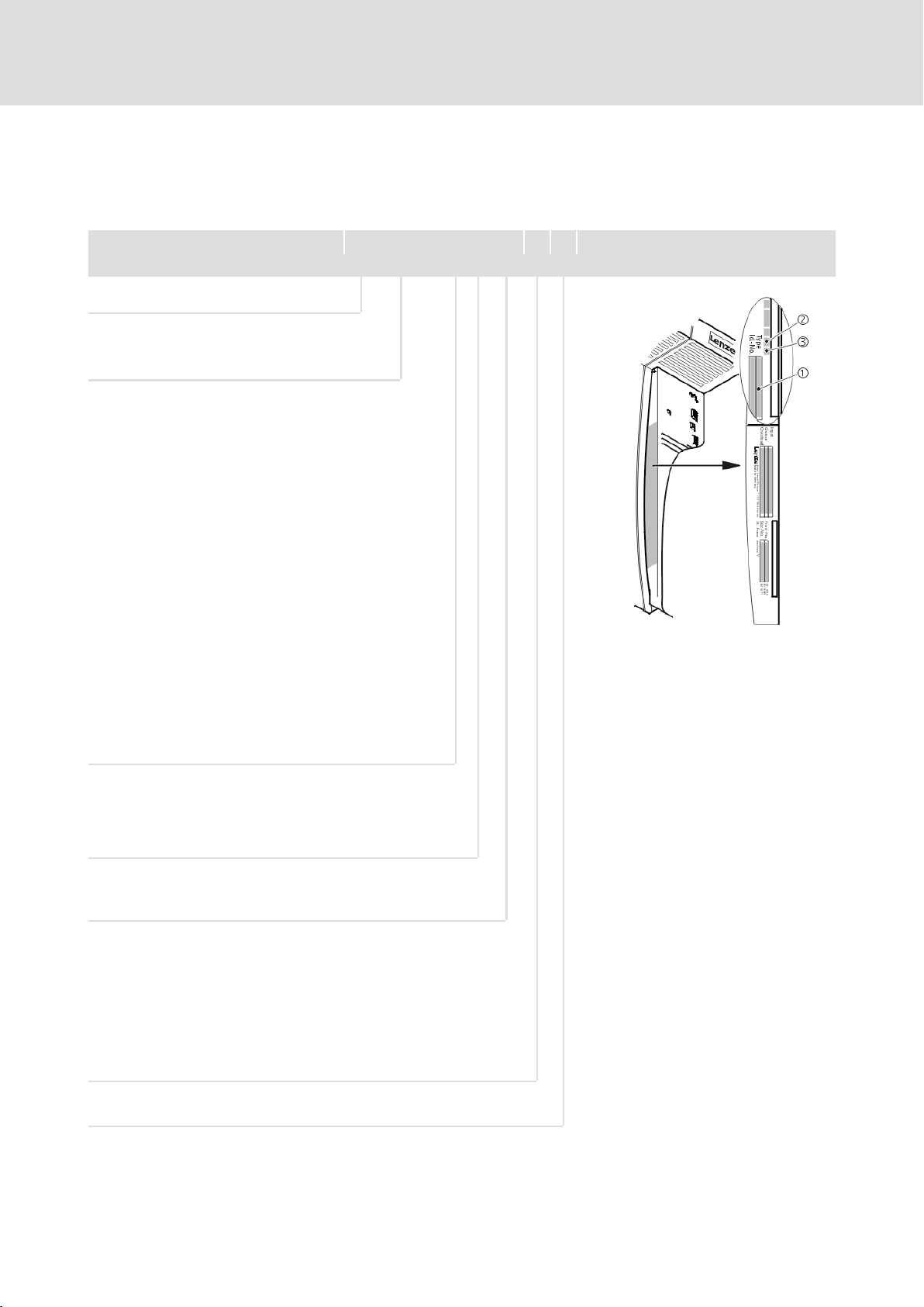
This documentation is valid for 9300 servo position controllers from
nameplate data:
Nameplate
EVS 93xx ˘ x x Vxx 6x 8x
Product range
EVS = servo controller
Type no. / rated power
400V 480 V
9321 = 0.37 kW 0.37 kW
9322 = 0.75 kW 0.75 kW
9323 = 1.5 kW 1.5 kW
9324 = 3.0 kW 3.0 kW
9325 = 5.5 kW 5.5 kW
9326 = 11 kW 11 kW
9327 = 15 kW 18.5 kW
3928 = 22 kW 30 kW
9329 = 30 kW 37 kW
9330 = 45 kW 45 kW
9331 = 55 kW 55 kW
9332 = 75 kW 90 kW
Type
E = panel−mounted unit
C = panel−mounted unit in "cold plate" technology
Model
P = servo position controller
Variant
˘ standard
V003 = in "cold plate" technology
V004 = with "safe torque off" function
V100 = for IT systems
V104 = with "safe torque off" function and for IT systems
9300vec112
Hardware version (from 6x)
Software version (from 8.0)
EDSVS9332P EN 5.0−07/2013
1.1−3
Page 16

1
1.1
1.1.3
Preface and general information
How to use this System Manual
Document history
1.1.3 Document history
What is new / what has
changed?
Material number Version Description
.M), 5.0 07/2013 TD06 Error corrections
13374993 4.2 03/2012 TD23 Error correction
13374993 4.1 05/2011 TD23 Error correction
13374993 4.0 04/2011 TD23 Extended by functions for software version
00463261 3.0 03/2003 TD23 Error correction and editorial revision
00406175 2.0 02/1999 − Types 9321 to 9324 with a double
00397653 1.0 05/1997 − First edition
8.0
Complete editorial revision and error
correction
Division of the System Manual into 2 parts
(EDSVS9332P and EDSVS9332P−EXT)
overcurrent, new function Automatic
control parameter identification"
1.1−4
EDSVS9332P EN 5.0−07/2013
Page 17

1.2 Legal regulations
Preface and general information
Legal regulations
1
1.2
Identification
Manufacturer
CE conformity
Application as directed
Lenze controllers are unambiguously identified by the contents of the
nameplate.
Lenze Automation GmbH, Hans−Lenze−Str. 1, D−31855 Aerzen, Germany
In conformity with EC "Low Voltage" Directive
9300 servo controllers and accessories
ƒ may only be operated under the conditions specified in this System
Manual.
ƒ are components
– for open and closed loop control of variable speed drives with PM
synchronous motors, asynchronous standard motors or asynchronous
servo motors.
– for installation in a machine.
– for assembly with other components to form a machine.
ƒ comply with the protection requirements of the EC "Low Voltage"
Directive.
ƒ are not machines for the purpose of the EC "Machinery" Directive.
ƒ are not to be used as domestic appliances, but only for industrial
purposes.
Drive systems with 9300 servo controllers
ƒ comply with the EC "Electromagnetic Compatibility" Directive if they
are installed according to the guidelines of CE−typical drive systems.
ƒ can be used
– for operation on public and non−public mains supplies.
– for operation in industrial premises and residential and commercial
areas.
ƒ The user is responsible for the compliance of the machine application
with the EC Directives.
Any other use shall be deemed inappropriate!
EDSVS9332P EN 5.0−07/2013
1.2−1
Page 18

1
1.2
Preface and general information
Legal regulations
Liability
Warranty
The information, data and notes given in this System Manual met the state
of the art at the time of printing. Claims on modifications referring to
controllers and components which have already been supplied cannot be
derived from the information, illustrations and descriptions contained in
this manual.
The procedural notes and circuit details given in this System Manual are
suggestions and their transferability to the respective application has to be
checked. Lenze does not take any responsibility for the suitability of the
given procedures and circuit suggestions.
The specifications given in this System Manual describe the product features
without guaranteeing them.
Lenze does not accept any liability for damage and malfunctioning caused
by:
ƒ Disregarding the System Manual
ƒ Unauthorised modifications to the controller
ƒ Operating faults
ƒ Improper working on and with the controller
See terms of sales and delivery of Lenze Automation GmbH.
Warranty claims must be made to Lenze immediately after detecting the
deficiency or fault.
The warranty is void in all cases where liability claims cannot be made.
1.2−2
EDSVS9332P EN 5.0−07/2013
Page 19

2 Safety instructions
Contents
2.1 General safety information 2.1−1. . . . . . . . . . . . . . . . . . . . . . . . . . . . . . . . . . .
2.2 Thermal motor monitoring 2.2−1. . . . . . . . . . . . . . . . . . . . . . . . . . . . . . . . . . .
2.2.1 Forced ventilated or naturally ventilated motors 2.2−2. . . . . . . . .
2.2.2 Self−ventilated motors 2.2−3. . . . . . . . . . . . . . . . . . . . . . . . . . . . . . .
2.3 Residual hazards 2.3−1. . . . . . . . . . . . . . . . . . . . . . . . . . . . . . . . . . . . . . . . . . . .
2.4 Safety instructions for the installation according to UL 2.4−3. . . . . . . . . . . .
Safety instructions
Contents
2
EDSVS9332P EN 5.0−07/2013
2−1
Page 20

Page 21

2.1 General safety information
Safety instructions
General safety information
2
2.1
Scope
For your own safety
The following general safety instructions apply to all Lenze drive and
automation components.
The product−specific safety and application notes given in this
documentation must be observed!
Note for UL−approved systems: UL warnings are notes which only apply to
UL systems. The documentation contains specific notes with regard to UL.
Danger!
Disregarding the following basic safety measures may lead to
severe personal injury and damage to material assets!
ƒ Lenze drive and automation components ...
... must only be used for the intended purpose.
... must never be operated if damaged.
... must never be subjected to technical modifications.
... must never be operated unless completely assembled.
... must never be operated without the covers/guards.
... can − depending on their degree of protection − have live, movable or
rotating parts during or after operation. Surfaces can be hot.
Transport, storage
ƒ All specifications of the corresponding enclosed documentation must
be observed.
This is vital for a safe and trouble−free operation and for achieving the
specified product features.
The procedural notes and circuit details provided in this document are
proposals which the user must check for suitability for his application.
The manufacturer does not accept any liability for the suitability of the
specified procedures and circuit proposals.
ƒ Only qualified skilled personnel are permitted to work with or on Lenze
drive and automation components.
According to IEC 60364 or CENELEC HD 384, these are persons ...
... who are familiar with the installation, assembly, commissioning and
operation of the product,
... possess the appropriate qualifications for their work,
... and are acquainted with and can apply all the accident prevent
regulations, directives and laws applicable at the place of use.
ƒ Transport and storage in a dry, low−vibration environment without
aggressive atmosphere; preferably in the packaging provided by the
manufacturer.
– Protect against dust and shocks
– Comply with climatic conditions according to the technical data.
.
EDSVS9332P EN 5.0−07/2013
2.1−1
Page 22

2
2.1
Safety instructions
General safety information
Mechanical installation
Electrical installation
ƒ Install the product according to the regulations of the corresponding
documentation. In particular observe the section "Operating
conditions" in the chapter "Technical data".
ƒ Provide for a careful handling and avoid mechanical overload. During
handling neither bend components, nor change the insulation
distances.
ƒ The product contains electrostatic sensitive devices which can easily be
damaged by short circuit or static discharge (ESD). Thus, electronic
components and contacts must not be touched unless ESD measures
are taken beforehand.
ƒ Carry out the electrical installation according to the relevant
regulations (e. g. cable cross−sections, fusing, connection to the PE
conductor). Additional notes are included in the documentation.
ƒ When working on live products, observe the applicable national
regulations for the prevention of accidents (e.g. BGV 3).
ƒ The documentation contains information about EMC−compliant
installation (shielding, earthing, arrangement of filters and laying
cables). The system or machine manufacturer is responsible for
compliance with the limit values required by EMC legislation.
Warning: The controllers are products which can be used in category C2
drive systems as per EN 61800−3. These products may cause radio
interference in residential areas. If this happens, the operator may need
to take appropriate action.
ƒ For compliance with the limit values for radio interference emission at
the site of installation, the components − if specified in the technical
data − have to be mounted in housings (e. g. control cabinets). The
housings have to enable an EMC−compliant installation. In particular
observe that for example control cabinet doors preferably have a
circumferential metallic connection to the housing. Reduce openings or
cutouts through the housing to a minimum.
ƒ Only plug in or remove pluggable terminals in the deenergised state!
Commissioning
Operation
Safety functions
2.1−2
ƒ If required, you have to equip the system with additional monitoring
and protective devices in accordance with the respective valid safety
regulations (e. g. law on technical equipment, regulations for the
prevention of accidents).
ƒ Before commissioning remove transport locking devices and keep them
for later transports.
ƒ Keep all protective covers and doors closed during operation.
ƒ Without a higher−level safety system, the described product must
neither be used for the protection of machines nor persons.
ƒ Certain controller versions support safety functions (e.g. "Safe torque
off", formerly "Safe standstill").
The notes on the safety functions provided in the documentation of the
versions must be observed.
EDSVS9332P EN 5.0−07/2013
Page 23

Safety instructions
General safety information
2
2.1
Maintenance and servicing
Disposal
ƒ The components are maintenance−free if the required operating
conditions are observed.
ƒ If the cooling air is polluted, the cooling surfaces may be contaminated
or the air vents may be blocked. Under these operating conditions, the
cooling surfaces and air vents must be cleaned at regular intervals.
Never use sharp objects for this purpose!
ƒ Only replace defective fuses in the deenergised state to the type
specified.
ƒ After the system has been disconnected from the supply voltage, live
components and power connections must not be touched immediately
because capacitors may be charged. Please observe the corresponding
notes on the device.
ƒ Recycle metals and plastic materials. Ensure professional disposal of
assembled PCBs.
EDSVS9332P EN 5.0−07/2013
2.1−3
Page 24

Page 25

2.2 Thermal motor monitoring
From software version 8.0 onwards, the 9300 controllers are provided with
2
an I
xt function for sensorless thermal monitoring of the connected motor.
Note!
2
ƒ I
calculates a thermal motor load from the detected motor
currents.
ƒ The calculated motor load is saved when the mains is
switched.
ƒ The function is UL−certified, i.e. no additional protective
measures are required for the motor in UL−approved systems.
ƒ However, I
influences on the motor load could not be detected as for
instance changed cooling conditions (e.g. interrupted or too
warm cooling air flow).
Safety instructions
Thermal motor monitoring
x t monitoring is based on a mathematical model which
2
x t monitoring is no full motor protection as other
2
2.2
2
x t load of the motor is displayed in C0066.
Die I
The thermal loading capacity of the motor is expressed by the thermal motor
time constant (t, C0128). Find the value in the rated motor data or contact
the manufacturer of the motor.
2
The I
x t monitoring has been designed such that it will be activated after
179 s in the event of a motor with a thermal motor time constant of
5 minutes (Lenze setting C0128), a motor current of 1.5 x I
and a trigger
N
threshold of 100 %.
Two adjustable trigger thresholds provide for different responses.
ƒ Adjustable response OC8 (TRIP, warning, off).
– The trigger threshold is set in C0127.
– The response is set in C0606.
– The response OC8, for instance, can be used for an advance warning.
ƒ Fixed response OC6−TRIP.
– The trigger threshold is set in C0120.
Behaviour of the I2 x t monitoring Condition
The I2 x t monitoring is deactivated.
C0066 is set = 0 % and
MCTRL−LOAD−I2XT is set = 0.00 %.
I2 x t monitoring is stopped.
The current value in C0066 and at the
MCTRL−LOAD−I2XT output is frozen.
I2 x t monitoring is deactivated.
The motor load is displayed in C0066.
When C0120 = 0 % and C0127 = 0 %, set
controller inhibit.
When C0120 = 0 % and C0127 = 0 %, set
controller enable.
Set C0606 = 3 (off) and C0127 > 0 %.
EDSVS9332P EN 5.0−07/2013
Note!
An error message OC6 or OC8 can only be reset if the I2 x t load
falls below the set trigger threshold by 5 %.
2.2−1
Page 26
2
2.2
2.2.1
Safety instructions
Thermal motor monitoring
Forced ventilated or naturally ventilated motors
2.2.1 Forced ventilated or naturally ventilated motors
Parameter setting
Calculate release time and
2
xt load
I
The following codes can be set for I
Code Meaning Value range Lenze setting
C0066 Display of the I2 x t load of the motor 0 ... 250 % −
C0120 Threshold: Triggering of error "OC6" 0 ... 120 % 0 %
C0127 Threshold: Triggering of error "OC8" 0 ... 120 % 0 %
C0128 Thermal motor time constant 0.1 ... 50.0 min 5.0 min
C0606 Response to error "OC8" TRIP, warning, off Warning
Formula for release time Information
ȡ
t +*(t) ln
ȧ
ȧ
1 *
Ȣ
Formulae for I2 x t load Information
2
I
Mot
ǒ
L(t) +
If the controller is inhibited, the I2 x t load is reduced:
Ǔ
100% ǒ1 * e
I
N
L(t) + L
Start
I
Mot
ǒ
I
N
Ǹ
e
z ) 1
2
Ǔ
100
*
*t
t
t
2
x t monitoring:
I
ȣ
ȧ
ȧ
Ȥ
Ǔ
t
Mot
I
r
t Thermal motor time constant (C0128)
z Threshold value in C0120 (OC6) or
L(t) Chronological sequence of the I2 x t
I
Mot
Ir Rated motor current (C0088)
t Thermal motor time constant (C0128)
L
Actual motor current (C0054)
Rated motor current (C0088)
C0127 (OC8)
load of the motor
(Display: C0066)
Actual motor current (C0054)
I2 x t load before controller inhibit
Start
If an error is triggered, the value
corresponds to the threshold value set
in C0120 (OC6) or
C0127 (OC8).
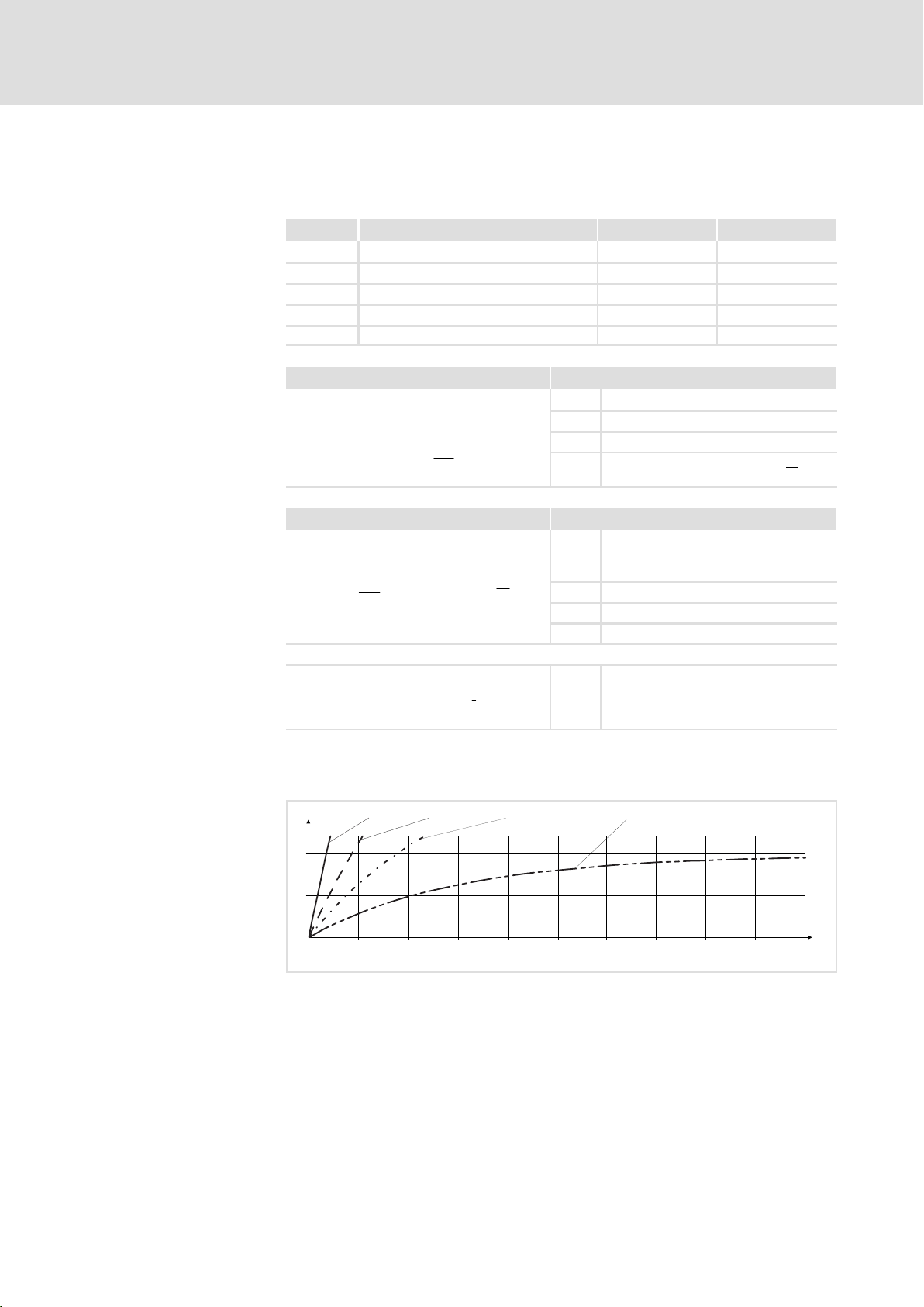
Read release time in the
diagram
Diagram for detecting the release times for a motor with a thermal motor
time constant of 5 minutes (Lenze setting C0128):
I = 3 × I
L [%]
Mot N
120
100
50
0
0 100 200 300 400 500 600 700 800 900
Fig. 2.2−1 I2 × t−monitoring: Release times for different motor currents and trigger
I = 2 × I
Mot N
thresholds
I
Actual motor current (C0054)
Mot
I
Rated motor current (C0088)
r
2
LI
T Time
x t load of the motor (display: C0066)
I = 1.5 × I
Mot N
I = 1 × I
Mot N
t [s]
1000
9300STD105
2.2−2
EDSVS9332P EN 5.0−07/2013
Page 27
2.2.2 Self−ventilated motors
Due to the construction, self−ventilated standard motors are exposed to an
increased heat generation in the lower speed range compared to forced
ventilated motors.
Warnings!
Safety instructions
Thermal motor monitoring
Self−ventilated motors
For complying with the UL 508C standard, you have to set the
speed−dependent evaluation of the permissible torque via code
C0129/x.
2.2.2
2
2.2
Parameter setting
Effect of code C0129/x
The following codes can be set for I2 x t monitoring:
Code Meaning Value range Lenze setting
C0066 Display of the I2 x t load of the motor 0 ... 250 % −
C0120 Threshold: Triggering of error "OC6" 0 ... 120 % 0 %
C0127 Threshold: Triggering of error "OC8" 0 ... 120 % 0 %
C0128 Thermal motor time constant 0.1 ... 50.0 min 5.0 min
C0606 Response to error "OC8" TRIP, warning, off Warning
C0129/1 S1 torque characteristic I1/I
C0129/2 S1 torque characteristics n2/n
I / I
N
1.1
1.0
3
0.9
0.8
0.7
0.6
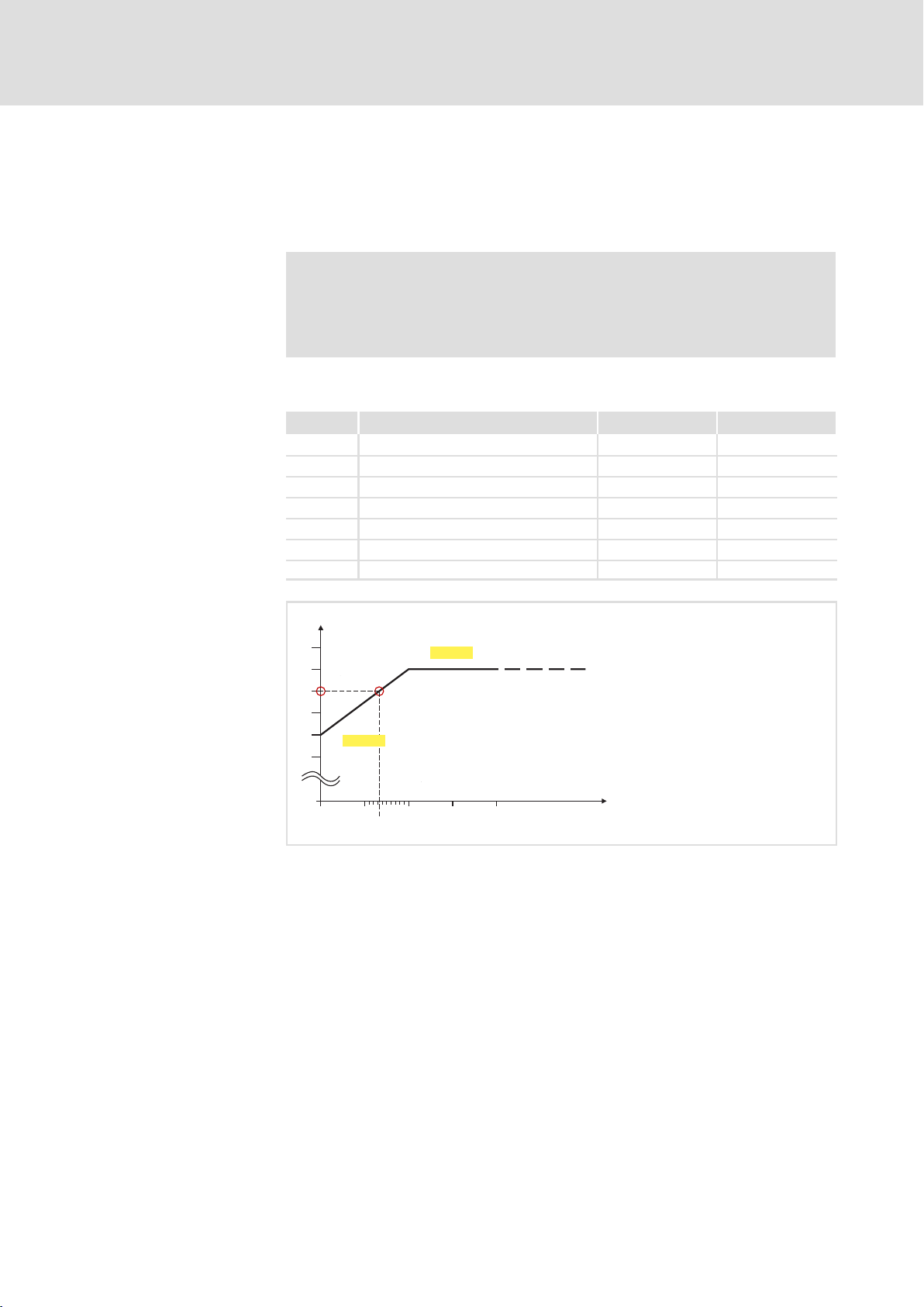
Fig. 2.2−2 Working point in the range of characteristic lowering
0
0
0 0.1
C0129/1
0.132
C0129/2
1
2
0.2 0.3 0.4
rated
rated
10 ... 200 % 100 %
10 ... 200 % 40 %
n / n
N
9300STD350
EDSVS9332P EN 5.0−07/2013
The lowered speed / torque characteristic (Fig. 2.2−2) reduces the
permissible thermal load of self−ventilated standard motors. The
characteristic is a line the definition of which requires two points:
ƒ Point : Definition with C0129/1
This value also enables an increase of the maximally permissible load.
ƒ Point : Definition with C0129/2
With increasing speeds, the maximally permissible load remains
unchanged (I
Mot
= I
rated
).
In Fig. 2.2−2, the motor speed and the corresponding permissible motor
torque () can be read for each working point (on the
characteristic () ... ). can also be calculated using the values in
C0129/1and C0129/2 (evaluation coefficient "y", 2.2−4).
2.2−3
Page 28
2
2.2
2.2.2
Safety instructions
Thermal motor monitoring
Self−ventilated motors
Calculate release time and
2
I
xt load
Calculate the release time and the I2 x t load of the motor considering the
values in C0129/1 and C0129/2(evaluation coefficient "y").
Formulae for release time Information
T Release time of the I2 x t monitoring
ȡ
I
Mot
ǒ
y I
n
Ǹ
e
z ) 1
2
Ǔ
100
N
n
) C0129ń1
N
t
*
t
T +*(t) ln
ȧ
ȧ
1 *
Ȣ
100% * C0129ń1
y +
Formulae for I2 x t load Information
If the controller is inhibited, the I2 x t load is reduced:
L(t) +
C0129ń2
I
Mot
ǒ
y I
L(t) + L
2
Ǔ
100% ǒ1 * e
N
Start
t Thermal motor time constant (C0128)
ȣ
In Function: Natural logarithm
ȧ
ȧ
I
Mot
Ȥ
I
r
z Threshold value in C0120 (OC6) or
y Evaluation coefficient
n
L(t) Chronological sequence of the I2 x t
y Evaluation coefficient
*t
Ǔ
t
I
Mot
Ir Rated motor current (C0088)
t Thermal motor time constant (C0128)
L
Actual motor current (C0054)
Rated motor current (C0088)
C0127 (OC8)
Rated speed (C0087)
rated
load of the motor
(Display: C0066)
Actual motor current (C0054)
I2 x t load before controller inhibit
Start
If an error is triggered, the value
corresponds to the threshold value set
in C0120 (OC6) or
C0127 (OC8).
2.2−4
EDSVS9332P EN 5.0−07/2013
Page 29

2.3 Residual hazards
Safety instructions
Residual hazards
2
2.3
Protection of persons
ƒ According to their enclosure, Lenze controllers (frequency inverters,
servo inverters, DC speed controllers) and their components can carry a
voltage, or parts of the controllers can move or rotate during operation.
Surfaces can be hot.
– If the required cover is removed, the controllers are used
inappropriately or installed or operated incorrectly, severe damage to
persons or material assets can occur.
– For more detailed information please see the documentation.
ƒ There is a high amount of energy within the controller. Therefore
always wear personal protective equipment (body protection,
headgear, eye protection, ear protection, hand guard) when working on
the controller when it is live.
ƒ Before working on the controller, check if no voltage is applied to the
power terminals.
– the power terminals U, V, W, +UG and −UG still carry dangerous
voltage for at least 3 minutes after power−off.
– the power terminals L1, L2, L3; U, V, W, +UG and −UG carry dangerous
voltage when the motor is stopped.
ƒ Before power−off during DC−bus operation, all controllers must be
inhibited and disconnected from the mains.
ƒ The discharge current to PE potential is > 3.5 mA. In accordance with
EN 61800−5−1
– a fixed installation is required.
– the design of the PE conductor has to be double or, in the case of a
single design, must have a cable cross−section of at least 10 mm
ƒ The controller can only be safely disconnected from the mains via a
contactor on the input side.
ƒ During parameter set transfer the control terminals of the controller
can have undefined states.
– Therefore the connectors X5 and X6 must be disconnected from the
controller before the transfer takes place. This ensures that the
controller is inhibited and all control terminals have the defined state
"LOW".
2
.
EDSVS9332P EN 5.0−07/2013
2.3−1
Page 30

2
2.3
Safety instructions
Residual hazards
ƒ Controllers can cause a DC current in the PE conductor. If a residual
current device (RCD) or a fault current monitoring unit (RCM) is used
for protection in the case of direct or indirect contact, only one
RCD/RCM of the following type can be used on the current supply side:
– Type B for the connection to a three−phase system
– Type A or type B for the connection to a single phase system
Alternatively another protective measure can be used, like for instance
isolation from the environment by means of double or reinforced
insulation, or isolation from the supply system by using a transformer.
Device protection
Motor protection
ƒ Frequent mains switching (e.g. inching mode via mains contactor) can
overload and destroy the input current limitation of the drive
controller:
– At least 3 minutes must pass between switching off and restarting
the devices EVS9321−xP and EVS9322−xP.
– At least 3 minutes must pass between two starting procedures of the
devices EVS9323−xP ... EVS9332−xP.
– Use the "safe torque off" safety function (STO) if safety−related mains
disconnections occur frequently. The drive variants Vxx4 are
equipped with this function.
ƒ For some controller settings, the connected motor may overheat (e.g.
when operating the DC injection brake or a self−ventilated motor at
low speed for longer periods).
– Using an overcurrent relay or a temperature monitoring device
provides a large degree of protection against overload.
– We recommend to use PTC thermistors or thermal contacts for motor
temperature monitoring. (Lenze three−phase AC motors are equipped
with thermal contacts (NC contacts) as standard)
– PTC thermistors or thermal contacts can be connected to the
controller.
2.3−2
ƒ Drives can attain dangerous overspeeds (e.g. setting of high output
frequencies with motors and machines not qualified for this purpose).
EDSVS9332P EN 5.0−07/2013
Page 31

Safety instructions
Safety instructions for the installation according to UL
2
2.4
2.4 Safety instructions for the installation according to UL
Warnings!
ƒ Motor Overload Protection
– For information on the protection level of the internal
overload protection for a motor load, see the corresponding
manuals or software helps.
– If the integral solid state motor overload protection is not
used, external or remote overload protection must be
provided.
ƒ Branch Circuit Protection
– The integral solid state protection does not provide branch
circuit protection.
– Branch circuit protection has to be provided externally in
accordance with corresponding instructions, the National
Electrical Code and any additional codes.
ƒ Please observe the specifications for fuses and
screw−tightening torques in these instructions.
ƒ EVS9321 EVS9326:
– Suitable for use on a circuit capable of delivering not more
than 5000 rms symmetrical amperes, 480 V maximum,
when protected by fuses.
– Suitable for use on a circuit capable of delivering not more
than 50000 rms symmetrical amperes, 480 V maximum,
when protected by CC, J, T or R class fuses.
– Maximum surrounding air temperature: 0 ... +55 °C
– > +40 °C: reduce the rated output current by 2.5 %/°C
– Use 75 °C copper wire only.
ƒ EVS9327 EVS9329:
– Suitable for use on a circuit capable of delivering not more
than 5000 rms symmetrical amperes, 480 V maximum,
when protected by fuses.
– Suitable for use on a circuit capable of delivering not more
than 50000 rms symmetrical amperes, 480 V maximum,
when protected by J, T or R class fuses.
– Maximum surrounding air temperature: 0 ... +50 °C
– > +40 °C: reduce the rated output current by 2.5 %/°C
– Use 60/75 °C or 75 °C copper wire only.
EDSVS9332P EN 5.0−07/2013
2.4−3
Page 32

2
2.4
Safety instructions
Safety instructions for the installation according to UL
ƒ EVS9330 EVS9332:
– Suitable for use on a circuit capable of delivering not more
than 10000 rms symmetrical amperes, 480 V maximum,
when protected by fuses.
– Suitable for use on a circuit capable of delivering not more
than 50000 rms symmetrical amperes, 480 V maximum,
when protected by J, T or R class fuses.
– Maximum surrounding air temperature: 0 ... +50 °C
– > +40 °C: reduce the rated output current by 2.5 %/°C
– Use 60/75 °C or 75 °C copper wire only.
2.4−4
EDSVS9332P EN 5.0−07/2013
Page 33

3 Technical data
Contents
3.1 General data and operating conditions 3.1−1. . . . . . . . . . . . . . . . . . . . . . . .
3.2 Open and closed loop control 3.2−1. . . . . . . . . . . . . . . . . . . . . . . . . . . . . . . . .
3.3 Rated data 3.3−1. . . . . . . . . . . . . . . . . . . . . . . . . . . . . . . . . . . . . . . . . . . . . . . . .
3.3.1 Operation at 400 V 3.3−1. . . . . . . . . . . . . . . . . . . . . . . . . . . . . . . . . .
3.3.2 Operation at 480 V 3.3−2. . . . . . . . . . . . . . . . . . . . . . . . . . . . . . . . . .
3.3.3 Overcurrent operation 3.3−4. . . . . . . . . . . . . . . . . . . . . . . . . . . . . . .
3.4 Current characteristics 3.4−1. . . . . . . . . . . . . . . . . . . . . . . . . . . . . . . . . . . . . . .
Technical data
Contents
3
EDSVS9332P EN 5.0−07/2013
3−1
Page 34

Page 35

General data and operating conditions
3.1 General data and operating conditions
Technical data
3
3.1
General data
Conformity and approval
Conformity
CE
Approval
UL cULus Power Conversion Equipment (File No. E132659)
Protection of persons and equipment
Type of protection EN 60529
Earth leakage current IEC/EN 61800−5−1 > 3.5 mA Observe regulations and
Insulation of control
circuits
Insulation resistance IEC/EN 61800−5−1
Protective measures Against short circuit, earth fault (earth−fault
2006/95/EC Low−Voltage Directive
2004/108/EG EMC Directive
IP20
IP41 in case of thermally separated installation
(push−through technique) between the control
cabinet (inside) and the environment.
NEMA 250 Protection against accidental contact in accordance
with type 1
safety instructions!
EN 61800−5−1 Safe mains isolation by double (reinforced)
insulation for terminals X1 and X5.
Basic insulation (single isolating distance) for
terminals X3, X4, X6, X7, X8, X9, X10 and X11.
< 2000 m site altitude: overvoltage category III
> 2000 m site altitude: overvoltage category II
protected during mains connection, limited
earth−fault protection during operation),
overvoltage, motor overtemperature (input for PTC
or thermal contact)
Operating conditions
EMC
Noise emission IEC/EN 61800−3
Interference
immunity
Ambient conditions
Climatic
Storage
Transport IEC/EN 60721−3−2 2K3 (−25 ... +70 °C)
Operation
EVS9321 ...
EVS9326
EVS9327 ...
EVS9332
Pollution EN 61800−5−1 Degree of pollution 2
IEC/EN 61800−3 Category C3
IEC/EN 60721−3−1
IEC/EN 60721−3−3
Cable−guided, up to 10 m motor cable length with
mains filter A: category C2.
Radiation, with mains filter A and installation in
control cabinet: category C2
1K3 (−25 ... +55 °C) < 6 months
1K3 (−25 ... +40 °C) > 6 months
3K3 (0 ... +55 °C)
> +40 °C: reduce the rated output current by
2.5 %/°C.
3K3 (0 ... +50 °C)
> +40 °C: reduce the rated output current by
2.5 %/°C.
> 2 years: anodise DC bus
capacitors
EDSVS9332P EN 5.0−07/2013
3.1−1
Page 36

3
3.1
Technical data
General data and operating conditions
Ambient conditions
Site altitude < 4000 m amsl
Mechanical
Vibration resistance EN 50178
EN 61800−5−1
Germanischer
Lloyd, general
conditions
Electrical
AC−mains
connection
Max. mains
voltage range
Mains frequency 45 Hz − 0 % ... 65 Hz + 0 %
Power system TT,
TN
Power system IT Operation only permitted with the device variants
Operation on
public supply
systems
DC−mains
connection
Max. mains
voltage range
Operating
conditions
Motor connection
Length of the
motor cable
EN 61000−3−2
> 1000 m amsl: reduce the rated output current by
5 %/ 1000 m
Tested according to "General Vibration Stress
Characteristic 1"
320 V − 0 % ... 528 V + 0 %
Operation permitted without restrictions with
earthed neutral.
V024 or V100.
Operation permitted without restrictions with
insulated neutral.
Observe instructions on specific measures!
Limitation of harmonic currents
Total output at the
mains
< 1 kW With mains choke.
> 1 kW Without additional
1)
The additional measures mentioned have the effect that solely
the controllers meet the requirements of EN 61000−3−2. The
machine/system manufacturer is responsible for the compliance
with the requirements for the machine/system!
450 V − 0 % ... 740 V + 0 %
DC voltage must be symmetrical to PE.
The controller will be destroyed when +U
are earthed.
< 50 m
No additional output filters are required at a rated
mains voltage and a switching frequency of 8 kHz.
If EMC requirements have to be met, the
permissible cable length may be affected.
Compliance with the
requirements
measures.
1)
or −U
G
G
3.1−2
Mounting conditions
Mounting place
Mounting position Vertical
Free spaces
Dimensions
Weights
In the control cabinet
4−1
EDSVS9332P EN 5.0−07/2013
Page 37

3.2 Open and closed loop control
Open and closed loopcontrol
Switching frequency 8 kHz or 16 kHz
Digital setpoint
selection
Accuracy ± 0.005 Hz (= ± 100 ppm)
Analog setpoint
selection
Linearity ± 0.15 % Signal level: 5 V or 10 V
Temperature
sensitivity
Offset ± 0.1 %
Analog inputs
Analog outputs
Digital inputs
Digital outputs
Cycle times
Digital inputs 1 ms
Digital outputs 1 ms
Analog inputs 1 ms
Analog outputs 1 ms (smoothing time: t= 2 ms)
± 0.1 % 0 ... 50 °C
l 2 inputs (bipolar)
l 2 outputs (bipolar)
l 5 inputs (freely assignable)
l 1 input for controller inhibit
l 4 outputs (freely assignable)
l 1 resolver input; design: 9−pole Sub−D socket
l 1 incremental encoder input (500 kHz, TTL level); design: 9−pole Sub−D socket (pin)
l 1 digital frequency input (500 kHz, TTL level); design: 9−pole Sub−D socket (pin); can be optionally
used as incremental encoder input (500 kHz, TTL level)
l 1 digital frequency output (500 kHz, TTL level); design: 9−pole Sub−D socket
Technical data
Open and closed loop control
3
3.2
EDSVS9332P EN 5.0−07/2013
3.2−1
Page 38

Page 39

3.3 Rated data
Note!
The controllers EVS9324, EVS9326 and EVS9328 EVS9333 may
only be operated with the prescribed mains chokes and mains
filters.
3.3.1 Operation at 400 V
Basis of the data
Voltage Frequency
AC mains connection [V
DC−mains connection
(alternatively)
Output voltage
With mains choke 3 ~ 0 approx. 94 % V
Without mains choke 3 ~ 0 ... U
rate
]
d
[UDC] DC 450 V − 0 % ... 620 V + 0 % ˘
3/PE AC 320 V − 0 % ... 440 V + 0 %
Technical data
Rated data
Operation at 400 V
45 Hz − 0 % ... 65 Hz + 0 %
rated
N
˘
˘
3
3.3
3.3.1
9300 Mains current
With
mains choke
Type Ir [A] Ir [A] Pr [kW] Pr [hp] S r8 [kVA] PDC [kW] P
EVS9321−xP 1.5 2.1 0.37 0.5 1.0 2.0 100
EVS9322−xP 2.5 3.5 0.75 1.0 1.7 0.75 110
EVS9323−xP 3.9 5.5 1.5 2.0 2.7 2.2 140
EVS9324−xP 7.0 ˘ 3.0 4.0 4.8 0.75 200
EVS9325−xP 12.0 16.8 5.5 7.5 9.0 0 260
EVS9326−xP 20.5 ˘ 11.0 15.0 16.3 0 390
EVS9327−xP 27.0 43.5 15.0 20.0 22.2 10 430
EVS9328−xP 44.0 ˘ 22.0 30.0 32.6 4 640
EVS9329−xP 53.0 ˘ 30.0 40.0 40.9 0 810
EVS9330−xP 78.0 ˘ 45.0 60.0 61.6 5 1100
EVS9331−xP 100 ˘ 55.0 75.0 76.2 0 1470
EVS9332−xP 135 ˘ 75.0 100 100.5 0 1960
1)
Without
mains choke
Bold print = Lenze setting
1)
Mains currents at 8 kHz switching frequency
2)
Switching frequency of the inverter
3)
Power which can additionally be drawn from the DC bus at operation with power−adapted motor
Typical motor power Output power Power loss
ASM
(4−pole)
2)
8 kHz
U, V, W +UG, −UG
3)
V
[W]
EDSVS9332P EN 5.0−07/2013
3.3−1
Page 40

3
3.3
3.3.2
9300 Output currents
Type Ir8 [A] I
EVS9321−xP 1.5 2.25 2.3 1.1 1.65 1.7
EVS9322−xP 2.5 3.75 3.8 1.8 2.7 2.7
EVS9323−xP 3.9 5.85 5.9 2.9 4.35 4.4
EVS9324−xP 7.0 10.5 10.5 5.2 7.8 7.8
EVS9325−xP 13.0 19.5 19.5 9.7 14.6 14.6
EVS9326−xP 23.5 35.3 23.5 15.3 23.0 15.3
EVS9327−xP 32.0 48.0 32.0 20.8 31.2 20.8
EVS9328−xP 47.0 70.5 47.0 30.6 45.9 30.6
EVS9329−xP 59.0 88.5 52.0 38.0 57.0 33.0
EVS9330−xP 89.0 133.5 80.0 58.0 87.0 45.0
EVS9331−xP 110 165 110 70.0 105 70.0
EVS9332−xP 145 21.5 126 90.0 135 72.0
Technical data
Rated data
Operation at 480 V
8 kHz
Rated current Maximum
current
[A] I08 [A] I
M8
Bold print = Lenze setting
1)
Switching frequency of the inverter
2)
The currents apply to a periodic load change cycle with max. 1 minute overcurrent duration and 2
minutes base load duration at max. 75 % I
1)
Standstill current Rated current Maximum
2)
[A] I
r16
r
1)
16 kHz
2)
current
[A] I
M16
Standstill current
016
[A]
3.3.2 Operation at 480 V
Basis of the data
Voltage Frequency
Supply
3/PE 480 V AC [Ur] 320 V − 0 % ... 528 V + 0 % 45 Hz − 0 % ... 65 Hz + 0 %
DC 678 V (alternatively) [UDC] 460 V − 0 % ... 740 V + 0 % ˘
Output voltage
With mains choke 3 ~ 0 ... approx. 94 % U
Without mains choke 3 ~ 0 ... U
r
r
˘
˘
3.3−2
EDSVS9332P EN 5.0−07/2013
Page 41

Technical data
Rated data
Operation at 480 V
3
3.3
3.3.2
9300 Mains current
With
mains choke
Type Ir [A] Ir [A] Pr [kW] Pr [hp] S r8 [kVA] PDC [kW] P
1)
Without
mains choke
Typical motor power Output power Power loss
ASM
(4−pole)
2)
8 kHz
U, V, W +UG, −UG
3)
[W]
V
EVS9321−xP 1.5 2.1 0.37 0.5 1.2 2.0 100
EVS9322−xP 2.5 3.5 0.75 1.0 2.1 0.75 110
EVS9323−xP 3.9 5.5 1.5 2.0 3.2 2.2 140
EVS9324−xP 7.0 ˘ 3.0 4.0 5.8 0.75 200
EVS9325−xP 12.0 16.8 5.5 7.5 10.8 0 260
EVS9326−xP 20.5 ˘ 11.0 15.0 18.5 0 390
EVS9327−xP 27.0 43.5 18.5 25.0 25.0 12 430
EVS9328−xP 44.0 ˘ 30.0 40.0 37.0 4.8 640
EVS9329−xP 53.0 ˘ 37.0 50.0 46.6 0 810
EVS9330−xP 78.0 ˘ 45.0 60.0 69.8 6 1100
EVS9331−xP 100 ˘ 55.0 75.0 87.3 0 1470
EVS9332−xP 135 ˘ 90.0 125 104 6 1960
Bold print = Lenze setting
1)
Mains currents at 8 kHz switching frequency
2)
Switching frequency of the inverter
3)
Power which can additionally be drawn from the DC bus at operation with power−adapted motor
9300 Output currents
Rated current Maximum
current
Type Ir8 [A] I
1)
8 kHz
Standstill current Rated current Maximum
2)
[A] I08 [A] I
M8
[A] I
r16
1)
16 kHz
2)
current
[A] I
M16
Standstill current
[A]
016
EVS9321−xP 1.5 2.25 2.3 1.1 1.65 1.7
EVS9322−xP 2.5 3.75 3.8 1.8 2.7 2.7
EVS9323−xP 3.9 5.85 5.9 2.9 4.35 4.4
EVS9324−xP 7.0 10.5 10.5 5.2 7.8 7.8
EVS9325−xP 13.0 19.5 19.5 9.7 14.6 14.6
EVS9326−xP 22.3 33.5 22.3 14.5 21.8 14.5
EVS9327−xP 30.4 45.6 30.4 19.2 28.8 19.2
EVS9328−xP 44.7 67.1 44.7 28.2 42.3 28.2
EVS9329−xP 56.0 84.0 49.0 35.0 52.5 25.0
EVS9330−xP 84.0 126 72.0 55.0 82.5 36.0
EVS9331−xP 105 157.5 105 65.0 97.5 58.0
EVS9332−xP 125 187.5 111 80.0 120 58.0
Bold print = Lenze setting
1)
Switching frequency of the inverter
2)
The currents apply to a periodic load change cycle with max. 1 minute overcurrent duration and 2
minutes base load duration at max. 75 % I
r
EDSVS9332P EN 5.0−07/2013
3.3−3
Page 42

3
3.3
3.3.3
Technical data
Rated data
Overcurrent operation
3.3.3 Overcurrent operation
Under the operating conditions described here, the
EVS9321−xP ... EVS9324−xP controllers can supply a rated output current
which is up to twice as high.
Note!
If you enter values > 1.5 × rated output current under C0022, the
controller switches to overcurrent operation.
ƒ Switching between overcurrent operation and standard
operation is only possible if the controller is inhibited
(X5/28 = LOW).
ƒ The continuous current is automatically reduced to 70 % of
the rated output current.
3.3.3.1 Operation at 400 V
Basis of the data
Voltage Frequency
AC mains connection [V
DC−mains connection
(alternatively)
Output voltage
With mains choke 3 ~ 0 approx. 94 % V
Without mains choke 3 ~ 0 ... U
rate
]
d
[UDC] DC 450 V − 0 % ... 620 V + 0 % ˘
3/PE AC 320 V − 0 % ... 440 V + 0 %
45 Hz − 0 % ... 65 Hz + 0 %
rated
N
˘
˘
9300 Mains current
With
mains choke
Type Ir [A] Ir [A] Pr [kW] Pr [hp] S r8 [kVA] PDC [kW] P
EVS9321−xP 1.5 2.1 0.37 0.5 1.0 2.0 100
EVS9322−xP 2.5 3.5 0.75 1.0 1.7 0.75 110
EVS9323−xP 3.9 5.5 1.5 2.0 2.7 2.2 140
EVS9324−xP 7.0 ˘ 3.0 4.0 4.8 0.75 200
1)
Without
mains choke
Bold print = Lenze setting
1)
Mains currents at 8 kHz switching frequency
2)
Switching frequency of the inverter
3)
Power which can additionally be drawn from the DC bus at operation with power−adapted motor
Typical motor power Output power Power loss
ASM
(4−pole)
2)
8 kHz
U, V, W +UG, −UG
3)
V
[W]
3.3−4
EDSVS9332P EN 5.0−07/2013
Page 43

Technical data
Rated data
Overcurrent operation
9300 Output currents
1)
8 kHz
Rated current Continuous
thermal
current
Type Ir8 [A] Ir8 [A] I
3)
Maximum
current
M8
Standstill
2)
current
[A] I08 [A] I
Rated current Continuous
thermal
current
[A] I
r16
[A] I
r16
EVS9321−xP 1.5 1.05 3.0 3.0 1.1 0.77 2.2 2.2
EVS9322−xP 2.5 1.75 5.0 5.0 1.8 1.26 3.6 3.6
EVS9323−xP 3.9 2.73 7.8 7.8 2.9 2.03 5.8 5.8
EVS9324−xP 7.0 4.9 14.0 14.0 5.2 3.64 10.4 10.4
1)
Switching frequency of the inverter
2)
The currents apply to a periodic load change cycle with max. 10 seconds overcurrent duration and
50 seconds base load duration at max. 44 % of the rated current
3)
70 % of the rated current
3.3.3.2 Operation at 480 V
Basis of the data
Voltage Frequency
Supply
3/PE 480 V AC [Ur] 320 V − 0 % ... 528 V + 0 % 45 Hz − 0 % ... 65 Hz + 0 %
DC 678 V (alternatively) [UDC] 460 V − 0 % ... 740 V + 0 % ˘
Output voltage
With mains choke 3 ~ 0 ... approx. 94 % U
Without mains choke 3 ~ 0 ... U
r
r
16 kHz
3)
1)
Maximum
current
M16
˘
˘
2)
[A] I
Standstill
current
016
3
3.3
3.3.3
[A]
9300 Mains current
With
mains choke
Type Ir [A] Ir [A] Pr [kW] Pr [hp] S r8 [kVA] PDC [kW] P
1)
Without
mains choke
Typical motor power Output power Power loss
ASM
(4−pole)
2)
8 kHz
U, V, W +UG, −UG
3)
[W]
V
EVS9321−xP 1.5 2.1 0.37 0.5 1.2 2.0 100
EVS9322−xP 2.5 3.5 0.75 1.0 2.1 0.75 110
EVS9323−xP 3.9 5.5 1.5 2.0 3.2 2.2 140
EVS9324−xP 7.0 ˘ 3.0 4.0 5.8 0.75 200
Bold print = Lenze setting
1)
Mains currents at 8 kHz switching frequency
2)
Switching frequency of the inverter
3)
Power which can additionally be drawn from the DC bus at operation with power−adapted motor
9300 Output currents
1)
8 kHz
Rated current Continuous
thermal
current
Maximum
3)
Type Ir8 [A] Ir8 [A] I
current
[A] I08 [A] I
M8
current
Standstill
2)
Rated current Continuous
thermal
current
[A] I
r16
[A] I
r16
16 kHz
3)
1)
Maximum
current
M16
2)
[A] I
Standstill
current
016
EVS9321−xP 1.5 1.05 3.0 3.0 1.1 0.77 2.2 2.2
EVS9322−xP 2.5 1.75 5.0 5.0 1.8 1.26 3.6 3.6
EVS9323−xP 3.9 2.73 7.8 7.8 2.9 2.03 5.8 5.8
EVS9324−xP 7.0 4.9 14.0 14.0 5.2 3.64 10.4 10.4
1)
Switching frequency of the inverter
2)
The currents apply to a periodic load change cycle with max. 10 seconds overcurrent duration and
50 seconds base load duration at max. 44 % of the rated current
3)
70 % of the rated current
[A]
EDSVS9332P EN 5.0−07/2013
3.3−5
Page 44

Page 45

3.4 Current characteristics
The maximum output current of the EVS9326 ... EVS9332 devices is limited
under certain operating conditions:
Technical data
Current characteristics
3
3.4
ƒ At output frequencies f
> 40° C.
J
K
< |5 Hz| and heatsink temperatures
out
ƒ The current limitation depends on the switching frequency.
01
I
OUT
I
max
I
0max
00
0055
<40°C
K
=80°C
K
fout [Hz] fout [Hz]
Fig. 3.4−1 Current derating characteristics
Operation at switching frequency f
The current limitation follows the characteristic curve
At output frequencies f
J
= 40 ... 80 °C, the current limit is steplessly adjusted in the range
K
Operation at switching frequency f
The current limitation follows the characteristic curve and is independent of
the heatsink temperature
At automatic change−over of the switching frequency (C0018 = 0), the controller
operates at f
curve .
= 16 kHz. The current limitation follows the characteristic
chop
If an increased torque is required (e.g. acceleration processes), the controller
automatically switches over to f
characteristic curve .
I
OUT
I
max
I
0max
= 8 kHz (C0018 = 1)
chop
< |5 Hz| and heatsink temperatures
out
= 16 kHz (C0018 = 2)
chop
= 8 kHz. The current limitation follows the
chop
9300vec132
9300
1)
[A]
= 8 kHz f
U
mains
f
chop
I
0max
I
0max
chop
[A]
= 16 kHz
U
mains
2)
400 V 480 V 400 V 480 V
EVS9326−xP 23.5 22.3 15.3 14.5
EVS9327−xP 32.0 30.4 20.8 19.2
EVS9328−xP 47.0 44.7 30.6 28.2
EVS9329−xP 52.0 49.0 33.0 25.0
EVS9330−xP 80.0 72.0 45.0 36.0
EVS9331−xP 110 105 70.0 58.0
EVS9332−xP 126 111 72.0 58.0
1)
Maximum available output current at an output frequency f
J
= 80 °C
K
2)
Maximum available output current at an output frequency f
= |0 Hz| and heatsink temperature
out
= |0 Hz|
out
EDSVS9332P EN 5.0−07/2013
3.4−1
Page 46

Page 47

Installing of the standard device
4 Installation of the standard device
4
Contents
Contents
4.1 Standard devices in the power range 0.37 ... 11 kW 4.1−1. . . . . . . . . . . . . . .
4.1.1 Important notes 4.1−1. . . . . . . . . . . . . . . . . . . . . . . . . . . . . . . . . . . . .
4.1.2 Mounting with fixing rails (standard) 4.1−2. . . . . . . . . . . . . . . . . . .
4.1.3 Thermally separated mounting (push−through technique) 4.1−3.
4.1.4 Mounting in "cold plate" technique 4.1−4. . . . . . . . . . . . . . . . . . . .
4.2 Standard devices in the power range 15 ... 30 kW 4.2−1. . . . . . . . . . . . . . . .
4.2.1 Important notes 4.2−1. . . . . . . . . . . . . . . . . . . . . . . . . . . . . . . . . . . . .
4.2.2 Mounting with fixing brackets (standard) 4.2−2. . . . . . . . . . . . . . .
4.2.3 Thermally separated mounting (push−through technique) 4.2−3.
4.2.4 Mounting in "cold plate" technique 4.2−4. . . . . . . . . . . . . . . . . . . .
4.3 Standard devices with a power of 45 kW 4.3−1. . . . . . . . . . . . . . . . . . . . . . . .
4.3.1 Important notes 4.3−1. . . . . . . . . . . . . . . . . . . . . . . . . . . . . . . . . . . . .
4.3.2 Mounting with fixing brackets (standard) 4.3−2. . . . . . . . . . . . . . .
4.3.3 Thermally separated mounting (push−through technique) 4.3−3.
4.3.4 Modification of the fan module for push−through technique 4.3−4
4.4 Standard devices in the power range 55 ... 75 kW 4.4−1. . . . . . . . . . . . . . . .
4.4.1 Important notes 4.4−1. . . . . . . . . . . . . . . . . . . . . . . . . . . . . . . . . . . . .
4.4.2 Mounting with fixing brackets (standard) 4.4−2. . . . . . . . . . . . . . .
4.4.3 Thermally separated mounting (push−through technique) 4.4−3.
EDSVS9332P EN 5.0−07/2013
4−1
Page 48

Page 49

Installing of the standard device
Standard devices in the power range 0.37 ... 11 kW
4.1 Standard devices in the power range 0.37 ... 11 kW
4.1.1 Important notes
Important notes
4
4.1
4.1.1
Mass of the devices
9300 Standard device "Cold plate" device
Type EVS93xx−EP
[kg]
EVS9321−xP 4.0 3.1
EVS9322−xP 4.0 3.1
EVS9323−xP 5.5 3.9
EVS9324−xP 5.5 3.9
EVS9325−xP 7.4 5.2
EVS9326−xP 7.4 5.2
EVS93xx−CP
[kg]
EDSVS9332P EN 5.0−07/2013
4.1−1
Page 50

4
4.1
4.1.2
Installing of the standard device
Standard devices in the power range 0.37 ... 11 kW
Mounting with fixing rails (standard)
4.1.2 Mounting with fixing rails (standard)
Mounting material required from the scope of supply:
Description Use
Fixing rails Drive controller fixing 2 4
Dimensions
120
LL
b1
b1
d
b
d
b
³ 100mm
³ 100mm
EVS9321−EP ...
EVS9324−EP
Quantity
EVS9325−EP
EVS9326−EP
Mounting
k
c
a
c1
a
c
e
g
9300std062
Fig. 4.1−1 Standard mounting with fixing rails 0.37 ... 11 kW
Drive controllers can be mounted side by side without spacing
9300 Dimensions [mm]
Type a b b1 c c1 d d1 e
EVS9321−EP
EVS9322−EP
EVS9323−EP
EVS9324−EP
EVS9325−EP
EVS9326−EP
1)
For a fieldbus module plugged onto X1, consider mounting space for connecting cables
78 384 350 39 − 365 ˘ 250 6.5 30
97 384 350 48.5 − 365 ˘ 250 6.5 30
135 384 350 21.5 92 365 ˘ 250 6.5 30
1)
g k
ƒ Attach the fixing rails to the housing of the drive controller.
4.1−2
EDSVS9332P EN 5.0−07/2013
Page 51

Installing of the standard device
Standard devices in the power range 0.37 ... 11 kW
Thermally separated mounting (push−through technique)
4.1.3 Thermally separated mounting (push−through technique)
For mounting in push−through technique you have to use the controller type
EVS93xx−EP. Additionally you will require the mounting set for
push−through technique:
Type Mounting set
EVS9321−EP, EVS9322−EP EJ0036
EVS9323−EP, EVS9324−EP EJ0037
EVS9325−EP, EVS9326−EP EJ0038
4
4.1
4.1.3
Dimensions
10
LL
Fig. 4.1−2 Dimensions for thermally separated mounting 0.37 ... 11 kW
9300 Dimensions [mm]
Type a a1 b b1 c c1 d d1 e
EVS9321−EP
EVS9322−EP
EVS9323−EP
EVS9324−EP
EVS9325−EP
EVS9326−EP
1)
For a fieldbus module plugged onto X1, consider mounting space for connecting cables
112.5 78 385.5 350 60 95.5 365.5 105.5 250 92 6.5
131.5 97 385.5 350 79 114.5 365.5 105.5 250 92 6.5
169.5 135 385.5 350 117 152.5 365.5 105.5 250 92 6.5
d1d1
b1b1
dd
gg
d1d1
cc
a1a1
c1c1
aa
bb
f
e
9300std063
1)
f g
Mounting cutout in control
cabinet
EDSVS9332P EN 5.0−07/2013
9300 Dimensions [mm]
Type Width Height
EVS9321−EP
EVS9322−EP
EVS9323−EP
EVS9324−EP
EVS9325−EP
EVS9326−EP
101 350
139 350
82 350
4.1−3
Page 52

4
4.1
4.1.4
Installing of the standard device
Standard devices in the power range 0.37 ... 11 kW
Mounting in "cold plate" technique
4.1.4 Mounting in "cold plate" technique
The drive controllers can be mounted in ˜cold plate˜ technique, e.g. on
collective coolers. For this purpose, the drive controllers of type EVS93xx−CPx
must be used.
Mounting material required from the scope of supply:
Requirements for collective
coolers
Description Use
EVS9321−CP
EVS9322−CP
Fixing bracket Controller fixing 2 2 2
Sheet metal screw
3.5 × 13 mm (DIN 7981)
Mounting the fixing
bracket to the controller
6 6 6
Quantity
EVS9323−CP
EVS9324−CP
EVS9325−CP
EVS9326−CP
The following points are important for safe and reliable operation of the
controller:
ƒ Good thermal connection to the cooler
– The contact surface between the collective cooler and the controller
must be at least as large as the cooling plate of the controller.
– Plane contact surface, max. deviation 0.05 mm.
– When attaching the collective cooler to the controller, make sure to
use all specified screw connections.
ƒ Observe the thermal resistance R
given in the table. The values are
th
valid for controller operation under rated conditions.
9300 Cooling path
Power to be dissipated Heatsink − environment
Type Pv [W] Rth [K/W]
EVS9321−CP 24 1.45
EVS9322−CP 42 0.85
EVS9323−CP 61 0.57
EVS9324−CP 105 0.33
EVS9325−CP 180 0.19
EVS9326−CP 360 0.10
Ambient conditions
4.1−4
ƒ The rated data and the derating factors at increased temperature also
apply to the ambient temperature of the drive controllers.
ƒ Temperature at the cooling plate of the drive controller: max. 75 °C.
EDSVS9332P EN 5.0−07/2013
Page 53

3
Dimensions
Installing of the standard device
Standard devices in the power range 0.37 ... 11 kW
Mounting in "cold plate" technique
LLL
dd d
b1 b1 b1
bb b
4
4.1
4.1.4
210
<75°C
Mounting
gg g
c
a
Fig. 4.1−3 Dimensions for mounting in "cold plate" technique 0.37 ... 11 kW
9300 Dimensions [mm]
Type a b b1 c c1 d e
EVS9321−CP
EVS9322−CP
EVS9323−CP
EVS9324−CP
EVS9325−CP
EVS9326−CP
1)
For a fieldbus module plugged onto X1, consider mounting space for connecting cables
78 381 350 48 ˘ 367 168 6.5
97 381 350 67 ˘ 367 168 6.5
135 381 350 105 38 367 168 6.5
c
a
c1
c
a
e
9300std064
1)
g
Apply heat conducting paste before screwing together the cooler and
cooling plate of the drive controller so that the heat transfer resistance is as
low as possible.
1. Fasten the fixing bracket with sheet metal screws 3.5 × 13 mm at the
top and bottom of the drive controller .
2. Clean the contact surface of cooler and cooling plate with spirit.
3. Apply a thin coat of heat conducting paste with a filling knife or brush.
– The heat conducting paste in the accessory kit is sufficient for an area
of approx. 1000 cm
2
.
EDSVS9332P EN 5.0−07/2013
4. Mount the drive controller on the cooler.
4.1−5
Page 54

Page 55

Installing of the standard device
Standard devices in the power range 15 ... 30 kW
4.2 Standard devices in the power range 15 ... 30 kW
4.2.1 Important notes
The accessory kit is located inside the controller.
Remove the cover of the drive controller
1. Remove the screws
2. Lift cover up and detach it
1
0
9300vec113
Important notes
4
4.2
4.2.1
Mass of the devices
9300 Standard device "Cold plate" device
Type EVS93xx−EP
[kg]
EVS9327−xP 13.5 9.5
EVS9328−xP 15.0 9.5
EVS9329−xP 15.0 ˘
EVS93xx−CP
[kg]
EDSVS9332P EN 5.0−07/2013
4.2−1
Page 56

4
4.2
4.2.2
Installing of the standard device
Standard devices in the power range 15 ... 30 kW
Mounting with fixing brackets (standard)
4.2.2 Mounting with fixing brackets (standard)
Mounting material required from the scope of supply:
Description Use Quantity
Fixing bracket Drive controller fixing 4
Raised countersunk head screw
M5 × 10 mm (DIN 966)
Dimensions
L
d
b1
b
Mounting of fixing bracket to the drive
controller
0
³ 100mm
³ 100mm
k
g
4
d1
Mounting
c1
a
c
e
m
9300std065
Fig. 4.2−1 Standard mounting with fixing brackets 15 ... 30 kW
Drive controllers can be mounted side by side without spacing
9300 Dimensions [mm]
Type a b b1 c c1 d d1 e
1)
g k m
EVS9327−EP
EVS9328−EP
250 402 350 22 206 370 24 250 6.5 24 11
EVS9329−EP
1)
For a fieldbus module plugged onto X1, consider mounting space for connecting cables
ƒ Attach the fixing brackets to the heatsink plate of the drive controller.
4.2−2
EDSVS9332P EN 5.0−07/2013
Page 57

Installing of the standard device
Standard devices in the power range 15 ... 30 kW
Thermally separated mounting (push−through technique)
4.2.3 Thermally separated mounting (push−through technique)
For mounting in push−through technique, the drive controller of type
EVS93xx−EPx must be used. In addition, the mounting set EJ0011 for the
push−through technique is required.
4
4.2
4.2.3
Dimensions
a
a1
L
d2
d
b
d3
d2
d1
h
h
Fig. 4.2−2 Dimensions for thermally separated mounting 15 ... 30 kW
9300 Dimensions [mm]
Type a a1 b b1 c1 c2 c3 d d1 d2 d3 e 1)e1 g h
EVS9327−EP
EVS9328−EP
EVS9329−EP
1)
For a fieldbus module plugged onto X1, consider mounting space for connecting cables
c1
c2
c3
279.5 250 379.5 350 19 131 243 361.5 32 100 97 250 159.5 6 9
g
b1
e1
e
9300std066
Mounting cutout in control
cabinet
EDSVS9332P EN 5.0−07/2013
9300 Dimensions [mm]
Type Width Height
EVS9327−EP
EVS9328−EP
EVS9329−EP
236 336
4.2−3
Page 58

4
4.2
4.2.4
Installing of the standard device
Standard devices in the power range 15 ... 30 kW
Mounting in "cold plate" technique
4.2.4 Mounting in "cold plate" technique
The drive controllers can be mounted in ˜cold plate˜ technique, e.g. on
collective coolers. For this purpose, the drive controllers of type EVS93xx−CPx
must be used.
Requirements for collective
coolers
Ambient conditions
The following points are important for safe and reliable operation of the
controller:
ƒ Good thermal connection to the cooler
– The contact surface between the collective cooler and the controller
must be at least as large as the cooling plate of the controller.
– Plane contact surface, max. deviation 0.05 mm.
– When attaching the collective cooler to the controller, make sure to
use all specified screw connections.
ƒ Observe the thermal resistance R
given in the table. The values are
th
valid for controller operation under rated conditions.
9300 Cooling path
Power to be dissipated Heatsink − environment
Type Pv [W] Rth [K/W]
EVS9327−CP 410 0.085
EVS9328−CP 610 0.057
ƒ The rated data and the derating factors at increased temperature also
apply to the ambient temperature of the drive controllers.
ƒ Temperature at the cooling plate of the drive controller: max. 75 °C.
4.2−4
EDSVS9332P EN 5.0−07/2013
Page 59

Dimensions
Installing of the standard device
Standard devices in the power range 15 ... 30 kW
Mounting in "cold plate" technique
L
4
4.2
4.2.4
Mounting
b1
g
c
c1
a
a1
Fig. 4.2−3 Dimensions for mounting in "cold plate" technique 15 ... 22 kW
9300 Dimensions [mm]
Type a a1 b b1 c c1 d e
EVS9327−CP
EVS9328−CP
1)
For a fieldbus module plugged onto X1, consider mounting space for connecting cables
234 250 381 350 110 220 367 171 6.5
d
b
<75°C
e
9300std067
1)
g
Apply heat conducting paste before screwing together the cooler and
cooling plate of the drive controller so that the heat transfer resistance is as
low as possible.
1. Clean the contact surface of cooler and cooling plate with spirit.
2. Apply a thin coat of heat conducting paste with a filling knife or brush.
– The heat conducting paste in the accessory kit is sufficient for an area
of approx. 1000 cm
2
.
3. Mount the drive controller on the cooler.
EDSVS9332P EN 5.0−07/2013
4.2−5
Page 60

Page 61

Installing of the standard device
Standard devices with a power of 45 kW
4.3 Standard devices with a power of 45 kW
4.3.1 Important notes
The accessory kit is located inside the controller.
Remove the cover of the drive controller
1
0
9300vec113
Important notes
1. Remove the screws
2. Lift cover up and detach it
4
4.3
4.3.1
Mass of the devices
9300 Standard device "Cold plate" device
Type EVS93xx−EP
[kg]
EVS9330−xP 38.0 ˘
EVS93xx−CP
[kg]
EDSVS9332P EN 5.0−07/2013
4.3−1
Page 62

4
4.3
4.3.2
Installing of the standard device
Standard devices with a power of 45 kW
Mounting with fixing brackets (standard)
4.3.2 Mounting with fixing brackets (standard)
Mounting material required from the scope of supply:
Description Use Quantity
Fixing bracket Drive controller fixing 4
Hexagon head cap screw
M8 × 16 mm (DIN 933)
Washer Æ 8.4 mm (DIN 125) For hexagon head cap screw 4
Spring washer Æ 8 mm (DIN 127) For hexagon head cap screw 4
Dimensions
l
b1
d
b
Mounting of fixing bracket to the drive
controller
0
³ 100 mm
³ 50 mm
³ 100mm
4
³ 50 mm
c
Mounting
k
g
m
d1
c1
a
e
9300std068
Fig. 4.3−1 Standard mounting with fixing brackets 45 kW
Arrange drive controllers in a row with spacing to be able to remove eye
bolts
9300 Dimensions [mm]
Type a b b1 c c1 d d1 e
1)
g k m
EVS9330−EP 340 580 591 28.5 283 615 38 285 11 28 18
1)
For a fieldbus module plugged onto X1, consider mounting space for connecting cables
ƒ Attach the fixing brackets to the heatsink plate of the drive controller.
4.3−2
EDSVS9332P EN 5.0−07/2013
Page 63

Installing of the standard device
Standard devices with a power of 45 kW
Thermally separated mounting (push−through technique)
4.3.3 Thermally separated mounting (push−through technique)
For mounting in push−through technique, the drive controller of type
EVS93xx−EPx must be used. In addition, the mounting set EJ0010 for the
push−through technique is required.
4
4.3
4.3.3
Dimensions
a
a1
d3
d2
d
b
d2
d2
d1
c1
h
h
g
c2
c3
c4
L
e2
e3
Fig. 4.3−2 Dimensions for thermally separated mounting 45 kW
b1
e1
e
9300std069
Mounting cutout in control
cabinet
EDSVS9332P EN 5.0−07/2013
9300 Dimensions [mm]
Type a a1 b b1 c1 c2 c3 c4 d d1d2 d3e1)e1 e2 e3g h
EVS9330−EP
1)
For a fieldbus module plugged onto X1, consider mounting space for connecting cables
37334054359145137.5217.53105254514581285163.51856
7 9
6
9300 Dimensions [mm]
Type Width Height
EVS9330−EP 320 515
4.3−3
Page 64

4
4.3
4.3.4
Installing of the standard device
Standard devices with a power of 45 kW
Modification of the fan module for push−through technique
4.3.4 Modification of the fan module for push−through technique
For thermally separated mounting the fan module has to be rotated by 180°
so that the controller fits into the mounting cutout.
Removing the fan module
Fig. 4.3−3 Removing the fan module from the controller
1. Remove both screws.
The screws connect the fans to the supply voltage.
2. Remove the 4 screws for fixing the fan module on each side.
9300vec170
Modifying the threaded
sleeves on the fan module
3. Pull back the fan module and carefully remove it to the top.
Make sure that the threaded sleeves do not touch the housing edge. They
may break off.
9300vec171
Fig. 4.3−4 Modifying the threaded sleeves for the voltage supply of the fans
1. Remove the threaded sleeves.
2. Screw−in the threaded sleeves on the opposite side and fasten them.
4.3−4
EDSVS9332P EN 5.0−07/2013
Page 65

Plugging the fan connecting
cable to another terminal on
the fan module
Installing of the standard device
Standard devices with a power of 45 kW
Modification of the fan module for push−through technique
4
4.3
4.3.4
Mounting the fan module in a
manner rotated by 180°
9300vec173
Fig. 4.3−5 Plugging the fan connecting cable for the voltage supply to another terminal
1. Remove the cable lugs of the two red connecting cables and plug them
in again on the diagonally arranged side.
2. Remove the cable lugs of the two blue connecting cables and plug
them in again on the diagonally arranged side.
9300vec172
Fig. 4.3−6 Mounting the fan module on the controller
1. Place the fan module onto the controller. Insert the lugs at the back
into the base plate .
Make sure that the threaded sleeves do not touch the housing edge. They
may break off.
EDSVS9332P EN 5.0−07/2013
2. Push the fan module to the front.
3. Screw−in and fasten the 4 screws for fixing the fan module on each
side.
4. Screw−in and fasten the two screws for the supply voltage.
4.3−5
Page 66

Page 67

Installing of the standard device
Standard devices in the power range 55 ... 75 kW
4.4 Standard devices in the power range 55 ... 75 kW
4.4.1 Important notes
The accessory kit is located inside the controller.
Remove the cover of the drive controller
1. Remove the screws
2. Lift cover up and detach it
1
0
9300vec113
Important notes
4
4.4
4.4.1
Mass of the devices
9300 Standard device "Cold plate" device
Type EVS93xx−EP
[kg]
EVS9331−xP 59.0 ˘
EVS9332−xP 59.0 ˘
EVS93xx−CP
[kg]
EDSVS9332P EN 5.0−07/2013
4.4−1
Page 68

4
4.4
4.4.2
Installing of the standard device
Standard devices in the power range 55 ... 75 kW
Mounting with fixing brackets (standard)
4.4.2 Mounting with fixing brackets (standard)
Mounting material required from the scope of supply:
Description Use Quantity
Fixing bracket Drive controller fixing 4
Hexagon head cap screw
M8 × 16 mm (DIN 933)
Washer Æ 8.4 mm (DIN 125) For hexagon head cap screw 8
Spring washer Æ 8 mm (DIN 127) For hexagon head cap screw 8
Dimensions
l
d
b1
b
For fixing bracket 8
0
³ 100mm
³ 100mm
³ 50mm
³ 50mm
c
Mounting
k
g
m
c1
d1
a
e
9300std070
Fig. 4.4−1 Standard mounting with fixing brackets 55 ... 75 kW
Arrange drive controllers in a row with spacing to be able to remove eye
bolts
9300 Dimensions [mm]
Type a b b1 c c1 d d1 e
EVS9331−EP
EVS9332−EP
1)
For a fieldbus module plugged onto X1, consider mounting space for connecting cables
450 750 680 28.5 393 702 38 285 11 28 18
1)
g k m
ƒ Attach the fixing brackets to the heatsink plate of the drive controller.
4.4−2
EDSVS9332P EN 5.0−07/2013
Page 69

Installing of the standard device
Standard devices in the power range 55 ... 75 kW
Thermally separated mounting (push−through technique)
4.4.3 Thermally separated mounting (push−through technique)
For mounting in push−through technique, the drive controller of type
EVS93xx−EPx must be used. In addition, the mounting set EJ0009 for the
push−through technique is required.
4
4.4
4.4.3
Dimensions
a
a1
d2
d
b
Fig. 4.4−2 Dimensions for thermally separated mounting 55 ... 75 kW
d2
d2
d1
h
c1
h
g
c2
c3
c4
L
b1
e1
e
9300std071
Mounting cutout in control
cabinet
EDSVS9332P EN 5.0−07/2013
9300 Dimensions [mm]
Typ a a1 b b1 c1 c2 c3 c4 d d1 d2 e 1)e1 g h
EVS9331−EP
EVS9332−EP
1)
For a fieldbus module plugged onto X1, consider mounting space for connecting cables
9300 Dimensions [mm]
Type a1 b1
EVS9331−EP
EVS9332−EP
488 450 718 680 49 172.5 295.5 419 698 49 200 285 164 9 10
428.5 660
4.4−3
Page 70

Page 71

5 Wiring of the standard device
Contents
5.1 Important notes 5.1−1. . . . . . . . . . . . . . . . . . . . . . . . . . . . . . . . . . . . . . . . . . . .
5.1.1 Protection of persons 5.1−1. . . . . . . . . . . . . . . . . . . . . . . . . . . . . . . .
5.1.2 Device protection 5.1−3. . . . . . . . . . . . . . . . . . . . . . . . . . . . . . . . . . .
5.1.3 Motor protection 5.1−3. . . . . . . . . . . . . . . . . . . . . . . . . . . . . . . . . . . .
5.2 Notes on project planning 5.2−1. . . . . . . . . . . . . . . . . . . . . . . . . . . . . . . . . . . .
5.2.1 Supply forms / electrical supply conditions 5.2−1. . . . . . . . . . . . . .
5.2.2 Operation on public supply systems (EN 61000−3−2) 5.2−1. . . . . .
5.2.3 Controllers in the IT system 5.2−2. . . . . . . . . . . . . . . . . . . . . . . . . . .
5.2.4 Operation at earth−leakage circuit breaker (e.l.c.b.) 5.2−3. . . . . . .
5.2.5 Interaction with compensation equipment 5.2−3. . . . . . . . . . . . . .
5.2.6 Discharge current for mobile systems 5.2−4. . . . . . . . . . . . . . . . . .
5.2.7 Optimisation of the controller and mains load 5.2−5. . . . . . . . . . .
5.2.8 Reduction of noise emissions 5.2−6. . . . . . . . . . . . . . . . . . . . . . . . . .
5.2.9 Mains choke/mains filter assignment 5.2−7. . . . . . . . . . . . . . . . . .
5.2.10 Motor cable 5.2−8. . . . . . . . . . . . . . . . . . . . . . . . . . . . . . . . . . . . . . . .
Wiring of the standard device
Contents
5
5.3 Basics for wiring according to EMC 5.3−1. . . . . . . . . . . . . . . . . . . . . . . . . . . .
5.3.1 Shielding 5.3−1. . . . . . . . . . . . . . . . . . . . . . . . . . . . . . . . . . . . . . . . . . .
5.3.2 Mains connection, DC supply 5.3−1. . . . . . . . . . . . . . . . . . . . . . . . . .
5.3.3 Motor cable 5.3−1. . . . . . . . . . . . . . . . . . . . . . . . . . . . . . . . . . . . . . . .
5.3.4 Control cables 5.3−3. . . . . . . . . . . . . . . . . . . . . . . . . . . . . . . . . . . . . .
5.3.5 Installation in the control cabinet 5.3−4. . . . . . . . . . . . . . . . . . . . . .
5.3.6 Wiring outside of the control cabinet 5.3−5. . . . . . . . . . . . . . . . . . .
5.3.7 Detecting and eliminating EMC interferences 5.3−6. . . . . . . . . . . .
5.4 Standard devices in the power range 0.37 ... 11 kW 5.4−1. . . . . . . . . . . . . . .
5.4.1 Wiring according to EMC (CE−typical drive system) 5.4−1. . . . . . . .
5.4.2 Important notes 5.4−3. . . . . . . . . . . . . . . . . . . . . . . . . . . . . . . . . . . . .
5.4.3 Mains connection, DC supply 5.4−4. . . . . . . . . . . . . . . . . . . . . . . . . .
5.4.4 Mains connection: Fuses and cable cross−sections 5.4−6. . . . . . . .
5.4.5 Mains choke/mains filter assignment 5.4−7. . . . . . . . . . . . . . . . . .
5.4.6 Motor connection 5.4−8. . . . . . . . . . . . . . . . . . . . . . . . . . . . . . . . . . .
5.5 Standard devices in the power range 15 ... 30 kW 5.5−1. . . . . . . . . . . . . . . .
5.5.1 Wiring according to EMC (CE−typical drive system) 5.5−1. . . . . . . .
5.5.2 Important notes 5.5−3. . . . . . . . . . . . . . . . . . . . . . . . . . . . . . . . . . . . .
5.5.3 Mains connection, DC supply 5.5−3. . . . . . . . . . . . . . . . . . . . . . . . . .
5.5.4 Mains connection: Fuses and cable cross−sections 5.5−5. . . . . . . .
5.5.5 Mains choke/mains filter assignment 5.5−6. . . . . . . . . . . . . . . . . .
5.5.6 Motor connection 5.5−7. . . . . . . . . . . . . . . . . . . . . . . . . . . . . . . . . . .
EDSVS9332P EN 5.0−07/2013
5−1
Page 72

5
Wiring of the standard device
Contents
5.6 Standard devices with a power of 45 kW 5.6−1. . . . . . . . . . . . . . . . . . . . . . . .
5.6.1 Wiring according to EMC (CE−typical drive system) 5.6−1. . . . . . . .
5.6.2 Important notes 5.6−3. . . . . . . . . . . . . . . . . . . . . . . . . . . . . . . . . . . . .
5.6.3 Mains connection, DC supply 5.6−4. . . . . . . . . . . . . . . . . . . . . . . . . .
5.6.4 Mains connection: Fuses and cable cross−sections 5.6−5. . . . . . . .
5.6.5 Mains choke/mains filter assignment 5.6−6. . . . . . . . . . . . . . . . . .
5.6.6 Motor connection 5.6−7. . . . . . . . . . . . . . . . . . . . . . . . . . . . . . . . . . .
5.7 Standard devices in the power range 55 ... 75 kW 5.7−1. . . . . . . . . . . . . . . .
5.7.1 Wiring according to EMC (CE−typical drive system) 5.7−1. . . . . . . .
5.7.2 Important notes 5.7−3. . . . . . . . . . . . . . . . . . . . . . . . . . . . . . . . . . . . .
5.7.3 Mains connection, DC supply 5.7−4. . . . . . . . . . . . . . . . . . . . . . . . . .
5.7.4 Mains connection: Fuses and cable cross−sections 5.7−5. . . . . . . .
5.7.5 Mains choke/mains filter assignment 5.7−6. . . . . . . . . . . . . . . . . .
5.7.6 Motor connection 5.7−7. . . . . . . . . . . . . . . . . . . . . . . . . . . . . . . . . . .
5.8 Control terminals 5.8−1. . . . . . . . . . . . . . . . . . . . . . . . . . . . . . . . . . . . . . . . . . .
5.8.1 Important notes 5.8−1. . . . . . . . . . . . . . . . . . . . . . . . . . . . . . . . . . . . .
5.8.2 Connection terminal of the control card 5.8−3. . . . . . . . . . . . . . . . .
5.8.3 Device variant without "Safe torque off" function 5.8−4. . . . . . . .
5.8.4 Device variant with "Safe torque off" function 5.8−5. . . . . . . . . . .
5.8.5 State bus 5.8−8. . . . . . . . . . . . . . . . . . . . . . . . . . . . . . . . . . . . . . . . . . .
5.8.6 Terminal assignment 5.8−9. . . . . . . . . . . . . . . . . . . . . . . . . . . . . . . .
5.8.7 Technical data 5.8−10. . . . . . . . . . . . . . . . . . . . . . . . . . . . . . . . . . . . . .
5.9 Wiring of the system bus (CAN) 5.9−1. . . . . . . . . . . . . . . . . . . . . . . . . . . . . . .
5.10 Wiring of the feedback system 5.10−1. . . . . . . . . . . . . . . . . . . . . . . . . . . . . . . .
5.10.1 Important notes 5.10−1. . . . . . . . . . . . . . . . . . . . . . . . . . . . . . . . . . . . .
5.10.2 Resolver at X7 5.10−2. . . . . . . . . . . . . . . . . . . . . . . . . . . . . . . . . . . . . .
5.10.3 Incremental encoder with TTL level at X8 5.10−3. . . . . . . . . . . . . . . .
5.10.4 SinCos encoder at X8 5.10−4. . . . . . . . . . . . . . . . . . . . . . . . . . . . . . . . .
5.11 Wiring of digital frequency input / digital frequency output 5.11−1. . . . . .
5−2
EDSVS9332P EN 5.0−07/2013
Page 73

5.1 Important notes
Stop!
5.1.1 Protection of persons
Danger!
Wiring of the standard device
Important notes
Protection of persons
The drive controller contains electrostatically sensitive
components.
The personnel must be free of electrostatic charge when carrying
out assembly and service operations.
Before working on the controller, check that all power terminals
are deenergised:
ƒ The power terminals U, V, W, +U
least 3 minutes after disconnection from the mains.
ƒ The power terminals L1, L2, L3, U, V, W, +U
live when the motor is stopped.
and −UG remain live for at
G
and −UG remain
G
5.1
5.1.1
5
Pluggable terminal strips
Connect or disconnect all pluggable terminals only in the deenergised state!
EDSVS9332P EN 5.0−07/2013
5.1−1
Page 74

5
5.1
5.1.1
Wiring of the standard device
Important notes
Protection of persons
Electrical isolation
The terminals X1 and X5 have double (reinforced) insulation according to
EN50178. The protection against accidental contact is ensured without
additional measured being taken.
Danger!
ƒ The terminals X3, X4, X6, X7, X8, X9, X10, X11 have basic
insulation (single isolating distance).
ƒ In the event of a defective isolating distance, protection
against accidental contact can only be guaranteed by taking
external measures such as double insulation.
ƒ If an external DC 24 V voltage source is used, the insulation
degree of the controller depends on the insulation degree of
the voltage source.
L1
Fig. 5.1−1 Electrical isolation between power terminals, control terminals and housing
24 VDC
N
ST1 ST2
X11
E5
E3
E4
39
L1
L2
L3
+U
-U
PE
U
V
W
PE
59
G
G
X3
X4X6X7
A1 A2
A3
A4
X8 X9 X10
E1 E2
X5
28
X1
9300std084
Double (reinforced) insulation
Basic insulation
Replacing defective fuses
Disconnecting the controller
from the mains
5.1−2
Only replace defective fuses in the deenergised state to the type specified.
Only carry out the safety−related disconnection of the controller from the
mains via a contactor on the input side or a manually operated toggle switch.
EDSVS9332P EN 5.0−07/2013
Page 75

5.1.2 Device protection
ƒ In the event of condensation, only connect the controller to the mains
ƒ The controller is protected by external fuses.
ƒ Drive controllers EVS9324−xP, EVS9326−xP and
ƒ Length of the screws for connecting the shield sheet for the control
ƒ Provide unused control inputs and outputs with terminal strips. Cover
ƒ Switching on the motor side of the controller is only permissible for
ƒ Frequent mains switching (e.g. inching mode via mains contactor) can
Wiring of the standard device
Important notes
Device protection
voltage after the humidity has evaporated.
EVS9328−xP ... EVS9332−xP must only be operated with assigned mains
choke / mains filter.
cables: 12 mm.
unused Sub−D sockets with protective covers included in the scope of
supply.
safety shutdown (emergency−off).
overload and destroy the input current limitation of the drive
controller:
– At least 3 minutes must pass between switching off and restarting
the devices EVS9321−xP and EVS9322−xP.
– At least 3 minutes must pass between two starting procedures of the
devices EVS9323−xP ... EVS9332−xP.
– Use the "safe torque off" safety function (STO) if safety−related mains
disconnections occur frequently. The drive variants Vxx4 are
equipped with this function.
5.1
5.1.2
5
5.1.3 Motor protection
ƒ Extensive protection against overload:
ƒ Only use motors with an insulation suitable for the inverter operation:
– By overcurrent relays or temperature monitoring.
– We recommend the use of PTC thermistors or thermostats to monitor
the motor temperature.
– PTC thermistors or thermostats can be connected to the controller.
– For monitoring the motor, we recommend the use of the I
monitoring.
– Insulation resistance: min. û = 1.5 kV, min. du/dt = 5 kV/ms
– When using motors with an unknown insulation resistance, please
contact your motor supplier.
2
xt
EDSVS9332P EN 5.0−07/2013
5.1−3
Page 76

Page 77

Wiring of the standard device
Supply forms / electrical supply conditions
5.2 Notes on project planning
5.2.1 Supply forms / electrical supply conditions
Observe the restrictions for the different supply forms!
Supply system Operation of controller Notes
Supply system: TT,
TN
(with earthed
neutral)
Supply system: IT
(with isolated
neutral)
DC supply via
+U
/−U
G
G
Permitted without restrictions.
Possible if the controller is
protected in the event of an earth
fault in the supply system
l by means of suitable devices
which detect the earth fault and
l immediately separate the
controller from the supply
system.
Permitted if the DC voltage is
symmetrical to PE.
Notes on project planning
l Observe the rated data of the
controller
l RMS mains current: see chapter
"Technical data".
l Safe operation in the event of an
earth fault at the inverter output
cannot be guaranteed.
l The variants V024 / V104 and
V100 enable operation of the
controller on IT systems.
Earthing of the +UG or −U
conductor will destroy the
controller.
5
5.2
5.2.1
G
5.2.2 Operation on public supply systems (compliance with EN 61000−3−2)
European standard EN 61000−3−2 defines limit values for the limitation of
harmonic currents in the supply system. Non−linear consumers (e.g.
frequency inverters) generate harmonic currents which "pollute" the
supplying mains and may therefore interfere with other consumers. The
standard aims at assuring the quality of public supply systems and reducing
the mains load.
Note!
The standard only applies to public systems. Mains which are
provided with a transformer substation of their own as in
industrial plants are not public and not included in the
application range of the standard.
If a device or machine consists of several components, the limit
values of the standard apply to the entire unit.
Measures for compliance with
the standard
With the measures described, the controllers comply with the limit values
according to EN 61000−3−2.
Operation on public
supply systems
1)
The additional measures mentioned have the effect that solely the controllers meet the
requirements of EN 61000−3−2. The machine/system manufacturer is responsible for the
compliance with the requirements for the machine/system!
EN 61000−3−2 Limitation of harmonic currents
Total power on the
mains
< 1 kW With mains choke
> 1 kW No measures required
Compliance with the requirements
1)
EDSVS9332P EN 5.0−07/2013
5.2−1
Page 78

5
5.2
5.2.3
Wiring of the standard device
Notes on project planning
Controllers in the IT system
5.2.3 Controllers in the IT system
Controllers in the V024, V104 or V100 variants are suitable for operation on
insulated supply systems (IT systems). The controllers also have an insulated
design. This avoids the activation of the insulation monitoring, even if
several controllers are installed.
The electric strength of the controllers is increased so that damage to the
controller are avoided if insulation or earth faults in the supply system occur.
The operational reliability of the system remains intact.
Stop!
Only operate the controllers with the mains chokes assigned.
Operation with mains filters or RFI filters by Lenze is not
permitted, as these modules contain components that are
interconnected against PE. By this the protective design of the IT
system would be cancelled out. The components are destroyed
in the case of an earth fault.
Protect the IT system against earth fault at the controller.
Due to physical conditions, an earth fault on the motor side at
the controller can interfere with or damage other devices on the
same IT system. Therefore appropriate measures have to be
implemented, by means of which the earth fault is detected and
which disconnect the controller from the mains.
Permissible supply forms and
electrical supply conditions
DC−bus operation of several
drives
Installation of the CE−typical
drive system
Mains Operation of the controllers Notes
With isolated star
point (IT systems)
Possible, if the controller is
protected in the event of an earth
fault in the supplying mains.
l Possible, if appropriate earth
fault detections are available
and
l the controller is immediately
disconnected from the mains.
Safe operation in the event of an
earth fault at the inverter output
cannot be guaranteed.
Central supply with 9340 regenerative power supply module is not possible.
For the installation of drives on IT systems, the same conditions apply as for
the installation on systems with an earthed neutral point.
According to the binding EMC product standard EN61800−3, no limit values
are defined for IT systems for noise emission in the high−frequency range.
5.2−2
EDSVS9332P EN 5.0−07/2013
Page 79

Wiring of the standard device
Operation at earth−leakage circuit breaker (e.l.c.b.)
5.2.4 Operation at earth−leakage circuit breaker (e.l.c.b.)
Danger!
The controllers are internally fitted with a mains rectifier. In case
of a short circuit to frame a pulsating DC residual current can
prevent the AC sensitive or pulse current sensitive earth−leakage
circuit breakers from being activated, thus cancelling the
protective function for the entire equipment being operated on
this earth−leakage circuit breaker.
ƒ For the protection of persons and farm animals (DIN VDE 0100), we
recommend
– pulse current sensitive earth−leakage circuit breakers for plants
including controllers with a single−phase mains connection (L1/N).
– universal−current sensitive earth−leakage circuit breakers for plants
including controllers with a three−phase mains connection (L1/L2/L3).
ƒ Only install the earth−leakage circuit breaker between supplying mains
and drive controller.
Notes on project planning
5
5.2
5.2.4
ƒ Earth−leakage circuit breakers may trigger a false alarm due to
– capacitive compensation currents flowing in the cable shields during
operation (particularly with long, shielded motor cables),
– simultaneous connection of several inverters to the mains
– the use of additional interference filters.
5.2.5 Interaction with compensation equipment
ƒ Controllers only consume very little reactive power of the fundamental
wave from the AC supply mains. Therefore, a compensation is not
required.
ƒ If the controllers are connected to a supply system with compensation
equipment, this equipment must comprise chokes.
– For this, contact the supplier of the compensation equipment.
EDSVS9332P EN 5.0−07/2013
5.2−3
Page 80

5
5.2
5.2.6
Wiring of the standard device
Notes on project planning
Discharge current for mobile systems
5.2.6 Discharge current for mobile systems
Frequency inverters with internal or external RFI filters usually have a
discharge current to PE potential that is higher than 3.5 mA AC or 10 mA DC.
Therefore, fixed installation as protection is required (see EN 61800−5−1).
This must be indicated in the operational documents.
If a fixed installation is not possible for a mobile consumer although the
discharge current to PE potential is higher than 3.5 mA AC or 10 mA DC, an
additional two−winding transformer (isolating transformer) can be included
in the current supply as a suitable countermeasure. Here, the PE conductor
is connected to the PEs of the drive (filter, inverter, motor, shieldings) and
also to one of the poles of the secondary winding of the isolating
transformer.
Devices with a three−phase supply must have a corresponding isolating
transformer with a secondary star connection, the star point being
connected to the PE conductor.
filter inverter
L1
prim.
N
PE
Fig. 5.2−1 Installation of a two−winding transformer (isolating transformer)
L1L1 LL2
sec.
N1 NN2
U
V
W
M
3~
8200vec017
5.2−4
EDSVS9332P EN 5.0−07/2013
Page 81

Wiring of the standard device
Optimisation of the controller and mains load
5.2.7 Optimisation of the controller and mains load
A mains choke is an inductance which can be included in the mains cable of
the frequency inverter. As a result, the load of the supplying mains and the
controller is optimised:
ƒ Reduced system perturbation: The curved shape of the mains current
approaches a sinusoidal shape.
ƒ Reduced mains current: The effective mains current is reduced, i.e. the
mains, cable, and fuse loads are reduced.
ƒ Increased service life of the controller: The electrolytic capacitors in the
DC bus have a considerably increased service life due to the reduced AC
current load.
There are no restrictions for the combinations of mains chokes and RFI filters
and/or motor filters. Alternatively, a mains filter can be used (combination
of mains choke and RFI filter in a common housing).
Notes on project planning
5
5.2
5.2.7
Note!
ƒ Some controllers must generally be operated with a mains
choke or a mains filter.
ƒ If a mains choke or a mains filter is used, the maximum
possible output voltage does not reach the value of the mains
voltage (typical voltage drop at the rated point 4 ... 6 %).
EDSVS9332P EN 5.0−07/2013
5.2−5
Page 82

5
5.2
5.2.8
Wiring of the standard device
Notes on project planning
Reduction of noise emissions
5.2.8 Reduction of noise emissions
Due to internal switching operations, every controller causes noise
emissions which may interfere with the functions of other consumers.
Depending on the site of the frequency inverter, European standard
EN 61800−3 defines limit values for these noise emissions:
Limit class C2: Limit class C2 is often required for industrial mains which are
isolated from the mains of residential areas.
Limit class C1: If the controller is operated in a residential area, it may
interfere with other devices such as radio and television receivers. Here,
interference suppression measures according to limit class C1 are often
required.
Limit class C1 is much more strict than limit class C2. Limit class C1 includes
limit class C2.
For compliance with limit class C1 / C2, corresponding measures for the
limitation of noise emissions are required, e.g. the use of RFI filters.
There are no restrictions for the combinations of RFI filters and mains chokes
and/or motor filters. Alternatively, a mains filter can be used (combination
of mains choke and RFI filter in a common housing).
The selection of the frequency inverter and the corresponding filters, if
applicable, always depends on the application in question and is determined
by e.g. the switching frequency of the controller, the motor cable length, or
the protective circuit (e.g. earth−leakage circuit breakers).
Note!
ƒ Some controllers must generally be operated with a mains
choke or a mains filter.
ƒ If a mains choke or a mains filter is used, the maximum
possible output voltage does not reach the value of the mains
voltage (typical voltage drop at the rated point 4 ... 6 %).
The graphics below illustrates the maximum possible motor cable length
based on the type of filter and the resulting interference voltage category
according to EN 61800−3. Depending on the used motor cable, the used
controller, and its switching frequency, the mentioned maximum motor
cable lengths may vary.
5.2−6
EDSVS9332P EN 5.0−07/2013
Page 83

Wiring of the standard device
Notes on project planning
Mains choke/mains filter assignment
5
5.2
5.2.9
E82ZZxxxxxB230
E82ZNxxxxxB230
EZN3A... ( 15 kW)³
EZN3A... ( 11 kW)£
1)
1)
5
10 20 30 405010
l [m]
mot
C1
EZN3B...
C2
E82ZNxxxxxB230
Fig. 5.2−2 Maximum motor cable lengths l
1) Use low−capacitance cables
5.2.9 Mains choke/mains filter assignment
9300 Mains choke Interference voltage category according to EN 61800−3 and motor cable length
Type C2 max. [m] C1 max. [m]
EVS9321−xP EZN3A2400H002 EZN3A2400H002 5 EZN3B2400H002 50
EVS9322−xP EZN3A1500H003 EZN3A1500H003 5 EZN3B1500H003 50
EVS9323−xP EZN3A0900H004 EZN3A0900H004 5 EZN3B0900H004 50
EVS9324−xP EZN3A0500H007 EZN3A0500H007 5 EZN3B0500H007 50
EVS9325−xP EZN3A0300H013 EZN3A0300H013 5 EZN3B0300H013 50
EVS9326−xP ELN3−0150H024−001 EZN3A0150H024 5 EZN3B0150H024 50
EVS9327−xP ELN3−0088H035−001 EZN3A0110H030 25
EVS9328−xP ELN3−0075H045
EVS9329−xP ELN3−0055H055
EVS9330−xP ELN3−0038H085
EZN3A0030H110N001
EVS9331−xP ELN3−0027H105
EVS9332−xP ELN3−0022H130
1)
RFI filter
2)
Footprint filter
3)
For controllers with thermal separation
1)
10 20 30 405010
based on the type of filter for compliance with
limit class C2 / C1
Component Component
E82ZN22334B230 50
E82ZZ15334B230
EZN3A0080H042 25 E82ZN22334B230 10
E82ZN22334B230 50 EZN3B0080H042 50
EZN3A0055H060 25 E82ZN30334B230 10
E82ZN30334B230 50 EZN3B0055H060 50
EZN3A0030H110 25
E82ZN55334B230 50
EZN3A0022H150 25 E82ZN75334B230 10
E82ZN75334B230 50 EZN3B0022H150 50
EZN3A0022H150 25 E82ZN75334B230 10
E82ZN75334B230 50 EZN3B0022H150 50
1)
3)
mot
E82ZN22334B230 10
E82ZZ15334B230
EZN3B0110H030U
50
25
l [m]
mot
1)
2)
EZN3B0030H110 50
9300vec060
10
50
EDSVS9332P EN 5.0−07/2013
5.2−7
Page 84

5
5.2
5.2.10
Wiring of the standard device
Notes on project planning
Motor cable
5.2.10 Motor cable
Specification
Cable length
ƒ The used motor cables must
– meet the requirements on site (e.g. EN 60204−1, UL),
– comply with the following voltage data: EN 0.6/1 kV, UL 600 V.
ƒ For shielded motor cables, only use cables with braid made of tinned or
nickel−plated copper. Shields made of steel braid are not suitable.
– The overlap rate of the braid must be at least 70 % with an overlap
angle of 90°.
ƒ Use low−capacitance motor cables:
Power class
3 ... 11 kW
15 ... 30 kW £ 140 pF/m £ 230 pF/m
45 ... 55 kW £ 190 pF/m £ 320 pF/m
75 ... 90 kW £ 250 pF/m £ 410 pF/m
9300 Maximum permissible motor cable length
Type f
EVS9321−xP,
EVS9322−xP
EVS9323−xP ...
EVS9332−xP
chop
50 m 45 m 50 m 25 m
50 m 50 m 50 m 50 m
from 2.5 mm
Ur = 400 V Ur = 480 V
= 8 kHz f
chop
Capacitance per unit length
Core/core Core/shield
2
£100 pF/m £ 150 pF/m
= 16 kHz f
= 8 kHz f
chop
chop
= 16 kHz
Note!
ƒ The motor cable must be as short as possible for having a
positive effect on the drive behaviour.
ƒ If EMC requirements must be met, the permissible cable
length may be affected.
ƒ EVS9321−xPand EVS9322−xP: At a mains voltage of 480 V and
a switching frequency f
permissible cable length is reduced if the motor cable has
more than a single core:
– The following holds true for two parallel single cores:
l
max
– The following holds true for three parallel single cores:
l
max
= 17 m
= 9 m
= 16 kHz, the maximum
chop
5.2−8
EDSVS9332P EN 5.0−07/2013
Page 85

Cable cross−section
Note!
The cable cross−sections have been assigned to the permissible
current loading of the motor cables under the following
conditions:
ƒ Compliance with IEC/EN 60204−1 for fixed cable installation
ƒ Compliance with IEC 60354−2−52, table A.52−5 when using the
cable in a trailing cable
ƒ Laying system C
ƒ Ambient temperature 45 °C
ƒ Continuous motor operation at a
– standstill current I
– rated current I
The user is responsible for selecting a motor cable which
complies with the requirements of the current conditions if
different situations arise. Different situations may arise due to:
ƒ Laws, standards, national and regional regulations
ƒ Type of application
ƒ Motor utilisation
ƒ Ambient and operating conditions
ƒ Laying system and bundling of cables
ƒ Cable type
Wiring of the standard device
Notes on project planning
Motor cable
for servo motors or a
0
for three−phase asynchronous motors
R
5
5.2
5.2.10
Motor cable
permanently installed for trailing cable Cable cross−section
IM [A] IM [A] [mm2] [AWG]
10.0 11.8 1.0 18
13.8 17.3 1.5 16
19.1 23.7 2.5 14
25.5 30.9 4.0 12
32.8 41.0 6.0 10
45.5 55.5 10 8
60.1 75.5 16 6
76.4 92.8 25 4
94.6 115 35 2
114 140 50 1
146 179 70 00
177 217 95 000
205 252 120 0000
Note!
Information on the design of the motor cable is provided in the
"System cables and system connectors" manual.
EDSVS9332P EN 5.0−07/2013
5.2−9
Page 86

Page 87

5.3 Basics for wiring according to EMC
5.3.1 Shielding
The quality of shielding is determined by a good shield connection:
ƒ Connect the shield with a large surface.
ƒ Connect the shield directly to the intended shield sheet of the device.
ƒ In addition, connect the shield to the conductive and earthed mounting
plate with a large contact surface by using a conductive clamp.
ƒ Unshielded cable ends must be as short as possible.
5.3.2 Mains connection, DC supply
ƒ Controllers, mains chokes, or mains filters may only be connected to
the mains via unshielded single cores or unshielded cables.
Wiring of the standard device
Basics for wiring according to EMC
Shielding
5
5.3
5.3.1
5.3.3 Motor cable
ƒ When a mains filter or RFI filter is used, shield the cable between mains
filter or RFI filter and controller if its length exceeds 300 mm.
Unshielded cores must be twisted.
ƒ In DC−bus operation or DC supply, use shielded cables.
ƒ The cable cross−section must be dimensioned for the assigned fusing
(observe national and regional regulations).
ƒ Only use shielded motor cables with braids made of tinned or
nickel−plated copper. Shields made of steel braids are not suitable.
– The overlap rate of the braid must be at least 70 % with an overlap
angle of 90 °.
ƒ The cables used must correspond to the requirements at the location
(e.g. EN 60204−1).
ƒ Shield the cable for motor temperature monitoring (PTC or thermal
contact) and install it separately from the motor cable.
– In Lenze system cables, the cable for brake control is integrated into
the motor cable. If this cable is not required for brake control, it can
also be used to connect the motor temperature monitoring up to a
length of 50 m.
EDSVS9332P EN 5.0−07/2013
ƒ Connect the shield with a large surface and fix it with metal cable
binders or a conductive clamp.
ƒ Connect the shield directly to the corresponding device shield sheet.
– If required, additionally connect the shield to the conductive and
earthed mounting plate in the control cabinet.
ƒ The motor cable is optimally installed if
– it is separated from mains cables and control cables,
– it only crosses mains cables and control cables at right angles,
5.3−1
Page 88

5
5.3
5.3.3
Wiring of the standard device
Basics for wiring according to EMC
Motor cable
– it is not interrupted.
ƒ If the motor cable must be opened all the same (e.g. due to chokes,
contactors, or terminals):
– The unshielded cable ends may not be longer than 100 mm
(depending on the cable cross−section).
– Install chokes, contactors, terminals etc. spatially separated from
other components (with a min. distance of 100 mm).
– Install the shield of the motor cable directly before and behind the
point of separation to the mounting plate with a large surface.
ƒ Connect the shield with a large surface to PE in the terminal box of the
motor at the motor housing.
– Metal EMC cable glands at the motor terminal box ensure a large
surface connection of the shield with the motor housing.
Motor supply cable Cable gland
Motor supply cable
max. 500mm
Braid
Cable gland
Large-surface
contactof
cable shield
Fig. 5.3−1 Shielding of the motor cable
Heat-shrinkable tube
8200EMV023 8200EMV024
Cablegland acc.toEMC with
high degree ofprotection
5.3−2
EDSVS9332P EN 5.0−07/2013
Page 89

5.3.4 Control cables
Wiring of the standard device
Basics for wiring according to EMC
Control cables
ƒ Control cables must be shielded to minimise interference injections.
ƒ For lengths of 200 mm and more, use only shielded cables for analog
and digital inputs and outputs. Under 200 mm, unshielded but twisted
cables may be used.
ƒ Connect the shield correctly:
– The shield connections of the control cables must be at a distance of
at least 50 mm from the shield connections of the motor cables and
DC cables.
– Connect the shield of digital input and output cables at both ends.
– Connect the shield of analog input and output cables at one end (at
the drive controller).
ƒ To achieve an optimum shielding effect (in case of very long cables,
with high interference) one shield end of analog input and output
cables can be connected to PE potential via a capacitor (e.g.
10 nF/250 V) (see sketch).
5.3.4
5
5.3
Fig. 5.3−2 Shielding of long, analog control cables
9300vec043
EDSVS9332P EN 5.0−07/2013
5.3−3
Page 90

5
5.3
5.3.5
Wiring of the standard device
Basics for wiring according to EMC
Installation in the control cabinet
5.3.5 Installation in the control cabinet
Mounting plate requirements
ƒ Only use mounting plates with conductive surfaces (zinc−coated or
V2A−steel).
ƒ Painted mounting plates are not suitable even if the paint is removed
from the contact surfaces.
ƒ If several mounting plates are used, ensure a large−surface connection
between the mounting plates (e.g. by using earthing strips).
Mounting of the components
ƒ Connect controllers, filters, and chokes to the earthed mounting plate
with a surface as large as possible.
Optimum cable routing
ƒ The motor cable is optimally installed if
– it is separated from mains cables and control cables,
– it crosses mains cables and control cables at right angles.
ƒ Always install cables close to the mounting plate (reference potential),
as freely suspended cables act like aerials.
ƒ Lead the cables to the terminals in a straight line (avoid tangles of
cables).
Earth connections
ƒ Use separated cable channels for motor cables and control cables. Do
not mix up different cable types in one cable channel.
ƒ Minimise coupling capacities and coupling inductances by avoiding
unnecessary cable lengths and reserve loops.
ƒ Short−circuit unused cores to the reference potential.
ƒ Install the positive and negative wires for DC 24 V close to each other
over the entire length to avoid loops.
ƒ Connect all components (drive controllers, chokes, filters) to a central
earthing point (PE rail).
ƒ Set up a star−shape earthing system.
ƒ Comply with the corresponding minimum cable cross−sections.
5.3−4
EDSVS9332P EN 5.0−07/2013
Page 91

5.3.6 Wiring outside of the control cabinet
Notes for cable routing outside the control cabinet:
ƒ The longer the cables the greater the space between the cables must
be.
ƒ If cables for different signal types are routed in parallel, the
interferences can be minimized by means of a metal barrier or
separated cable ducts.
Cover
Wiring of the standard device
Basics for wiring according to EMC
Wiring outside of the control cabinet
Barrier without
opening
5
5.3
5.3.6
Signal cables
Fig. 5.3−3 Cable routing in the cable duct with barrier
Cableduct
Fig. 5.3−4 Cable routing in separated cable ducts
Power cables
Cover
Communication cables
Measuring cables
Analog cables
Control cables
Power cables
EMVallg001
EMVallg002
EDSVS9332P EN 5.0−07/2013
5.3−5
Page 92

5
5.3
5.3.7
Wiring of the standard device
Basics for wiring according to EMC
Detecting and eliminating EMC interferences
5.3.7 Detecting and eliminating EMC interferences
Fault Cause Remedy
Interferences of
analog setpoints of
your own or other
devices and
measuring systems
Conducted
interference level is
exceeded on the
supply side
Unshielded motor cable
Shield contact is not extensive
enough
Shield of the motor cable is
interrupted by terminal strips,
switched, etc.
Install additional unshielded
cables inside the motor cable (e.g.
for motor temperature
monitoring)
Too long and unshielded cable
ends of the motor cable
Terminal strips for the motor
cable are directly located next to
the mains terminals
Mounting plate varnished Optimise PE connection:
HF short circuit Check cable routing
Use shielded motor cable
Carry out optimal shielding as
specified
l Separate components from
other component part with a
minimum distance of 100 mm
l Use motor choke/motor filter
Install and shield additional cables
separately
Shorten unshielded cable ends to
maximally 40 mm
Spatially separate the terminal
strips for the motor cable from
main terminals and other control
terminals with a minimum
distance of 100 mm
l Remove varnish
l Use zinc−coated mounting
plate
5.3−6
EDSVS9332P EN 5.0−07/2013
Page 93

Wiring of the standard device
Standard devices in the power range 0.37 ... 11 kW
Wiring according to EMC (CE−typical drive system)
5.4 Standard devices in the power range 0.37 ... 11 kW
5.4.1 Wiring according to EMC (CE−typical drive system)
The drives comply with the EC Directive on "Electromagnetic Compatibility"
if they are installed in accordance with the specifications for the CE−typical
drive system. The user is responsible for the compliance of the machine
application with the EC Directive.
Note!
Observe the notes given in the chapter "Basics for wiring
according to EMC"!
5
5.4
5.4.1
EDSVS9332P EN 5.0−07/2013
5.4−1
Page 94

5
5.4
5.4.1
L1
L2
L3
N
PE
Wiring of the standard device
Standard devices in the power range 0.37 ... 11 kW
Wiring according to EMC (CE−typical drive system)
F1…F3
K10
PE
Z2
PE L1 L2
PES
+
DC 24 V
–
PES
PES PES
X11
K31
K32
33
34
X5
28
E1
E2
E3
EVS9321 …
E4
EVS9332
E5
ST1
ST2
39
A1
A2
A3
A4
59
PESPES
T1 T2
PEUVW
IN1
Z1
IN2
IN3
IN4
L3
X4
HI
LO
GND
PES
X6
63
7
62
7
4
3
2
1
X7
X8
X9
X10
-UG
PES
PES
+UG
S2
S1
K10
K10
PE
PES
PES
J>
PE PE
M
3~
X7/8
X7/9
KTY
PES PES
PESPES
M
PES
3~
Fig. 5.4−1 Example for wiring in accordance with EMC regulations
F1 ... F3 Fuses
K10 Mains contactor
Z1 Programmable logic controller (PLC)
Z2 Mains choke or mains filter
Z3 EMB9351−E brake module
S1 Mains contactor on
S2 Mains contactor off
+U
G
, −U
G
DC−bus connection
PES HF shield termination through large−surface connection to PE
PES
PES
PE
PE
-UG
+UG
RB
JRB
9351
PES
PES
T2T1
Z3
9300std072
5.4−2
EDSVS9332P EN 5.0−07/2013
Page 95

5.4.2 Important notes
To gain access to the power connections, remove the covers:
ƒ Release the cover for the mains connection with slight pressure on the
ƒ Release the cover for the motor connection with slight pressure on the
Installation material required from the scope of supply:
Description Use Quantity
Shield connection support Support of the shield sheets for the supply
Hexagon nut M5
Spring washer Æ 5 mm (DIN 127) 2
Serrated lock washer Æ 5.3 mm
(DIN 125)
Shield sheet Shield connections for supply cables, motor
Screw and washer assembly
M4 × 10 mm (DIN 6900)
Wiring of the standard device
Standard devices in the power range 0.37 ... 11 kW
front and pull it off to the top.
front and pull it off to the bottom.
cable and motor cable
Fastening of shield connection supports
cable
Fastening of shield sheets 4
Important notes
5
5.4
5.4.2
2
4
2
2
EDSVS9332P EN 5.0−07/2013
5.4−3
Page 96

5
5.4
5.4.3
Wiring of the standard device
Standard devices in the power range 0.37 ... 11 kW
Mains connection, DC supply
5.4.3 Mains connection, DC supply
Note!
ƒ If a mains filter or RFI filter is used and the cable length
between mains/RFI filter and drive controller exceeds
300 mm, install a shielded cable.
ƒ For DC−bus operation or DC supply, we recommend using
shielded DC cables.
Shield sheet installation
Stop!
ƒ To avoid damaging the PE stud, always install the shield sheet
and the PE connection in the order displayed. The required
parts are included in the accessory kit.
ƒ Do not use lugs as strain relief.
0
M6
M5
Fig. 5.4−2 Installation of shield sheet for drive controllers 0.37 ... 11 kW
PE stud
Screw on M5 nut and tighten hand−tight
Slide on fixing bracket for shield sheet
Slide on serrated lock washer
Slide on PE cable with ring cable lug
Slide on washer
Slide on spring washer
Screw on M5 nut and tighten it
Screw shield sheet on fixing bracket with two M4 screws (a)
}
8
7
4
2
0
PE
+
9300vec130
1
2
3
4
5
6
7
a
1.7 Nm
15 lb-in
L1 L2 L3
a
+UG -UG
PE
M5
PE
3.4Nm
30 lb-in
5.4−4
EDSVS9332P EN 5.0−07/2013
Page 97

Wiring of the standard device
Standard devices in the power range 0.37 ... 11 kW
Mains connection, DC supply
5
5.4
5.4.3
Mains connection, DC supply
0
1
2
+UG -UG
L1 L2 L3
PE
L1, L2, L3
+U , -U
GG
0.5...0.6 Nm
4.4...5.3 lb-in
Fig. 5.4−3 Mains connection, DC supply for drive controllers 0.37 ... 11 kW
Mains cable
Shield sheet
Securely clamp mains cable with the lugs
Mains and DC bus connection
L1, L2, L3: Connection of mains cable
, −UG: Connection of DC−bus components or connection of the controller
+U
G
in the DC−bus system (see system manual)
Cable cross−sections up to 4 mm
Cable cross−sections > 4 mm
2
: Use wire end ferrules for flexible cables
2
: Use pin−end connectors
9300std033
EDSVS9332P EN 5.0−07/2013
5.4−5
Page 98

5
5.4
5.4.4
Wiring of the standard device
Standard devices in the power range 0.37 ... 11 kW
Mains connection: Fuses and cable cross−sections
5.4.4 Mains connection: Fuses and cable cross−sections
Installation in accordance
with EN 60204−1
Supply conditions
Range Description
Fuses l Utilisation category: only gG/gL or gRL
Cables Laying systems B2 and C: Use of PVC−insulated copper cables, conductor
RCCB l Controllers can cause a DC current in the PE conductor. If a residual current
Observe all national and regional regulations!
9300 Rated fuse current Cable cross−section FI
Type [A] [A] [mm2] [mm2] [mA]
Operation without mains choke/mains filter
EVS9321−xP 6 C6, B6
EVS9322−xP 6 C6, B6
EVS9323−xP 10 B10 1.5 1
EVS9325−xP 25 B20 4 2.5
Operation with mains choke/mains filter
EVS9321−xP 6 C6, B6
EVS9322−xP 6 C6, B6
EVS9323−xP 10 B10 1.5 1
EVS9324−xP 10 B10 1.5 1
EVS9325−xP 20 B16 2.5 2.5
EVS9326−xP 32 B25 ˘ 4
1)
Universal current−sensitive earth−leakage circuit breaker
2)
For short−time mains interruptions, use circuit breakers with tripping characteristic "C"
temperature < 70 °C, ambient temperature < 40 °C, no bundling of the cables or
cores, three loaded cores. The data are recommendations. Other
dimensionings/laying systems are possible (e.g. in accordance with VDE 0298−4).
device (RCD) or a fault current monitoring unit (RCM) is used for protection in
the case of direct or indirect contact, only one RCD/RCM of the following type
can be used on the current supply side:
– Type B (universal−current sensitive) for connection to a three−phase system
– Type A (pulse−current sensitive) or type B (universal−current sensitive) for
connection to a 1−phase system
Alternatively another protective measure can be used, like for instance
isolation from the environment by means of double or reinforced insulation,
or isolation from the supply system by using a transformer.
l Earth−leakage circuit breakers must only be installed between mains supply
and controller.
Fuse Circuit−breaker Laying system L1, L2, L3, PE
B2 C
2)
2)
2)
2)
1 1
1 1
1 1
1 1
300
300
1)
5.4−6
EDSVS9332P EN 5.0−07/2013
Page 99

Wiring of the standard device
Standard devices in the power range 0.37 ... 11 kW
Mains choke/mains filter assignment
5
5.4
5.4.5
Installation to UL
Supply conditions
Range Description
Fuses l Only in accordance with UL 248
l System short−circuit current up to 5000 A
l System short−circuit current up to 50000 A
"R" permissible
Cables l Only in accordance with UL
l The cable cross−sections specified in the following apply under the following
conditions:
– Conductor temperature < 60 °C
– Ambient temperature < 40 °C
Observe all national and regional regulations!
9300 Rated fuse current Cable cross−section
Fuse L1, L2, L3, PE
Type [A] [AWG]
Operation without mains choke/mains filter
EVS9321−xP
EVS9322−xP 6 18
EVS9323−xP 10 16
EVS9325−xP 25 10
Operation with mains choke/mains filter
EVS9321−xP 6 18
EVS9322−xP 6 18
EVS9323−xP 10 16
EVS9324−xP 10 16
EVS9325−xP 25 10
EVS9326−xP 25 10
Max. connection cross−section of the terminal strip: AWG 12, with pin−end connector AWG 10
6 18
: All classes are permissible
rms
: Only classes "CC", "J", "T" or
rms
5.4.5 Mains choke/mains filter assignment
9300 Mains choke Interference voltage category according to EN 61800−3 and motor cable length
Component Component
Type C2 max. [m] C1 max. [m]
EVS9321−xP EZN3A2400H002 EZN3A2400H002 5 EZN3B2400H002 50
EVS9322−xP EZN3A1500H003 EZN3A1500H003 5 EZN3B1500H003 50
EVS9323−xP EZN3A0900H004 EZN3A0900H004 5 EZN3B0900H004 50
EVS9324−xP EZN3A0500H007 EZN3A0500H007 5 EZN3B0500H007 50
EVS9325−xP EZN3A0300H013 EZN3A0300H013 5 EZN3B0300H013 50
EVS9326−xP ELN3−0150H024−001 EZN3A0150H024 5 EZN3B0150H024 50
EDSVS9332P EN 5.0−07/2013
5.4−7
Page 100

5
5.4
5.4.6
Wiring of the standard device
Standard devices in the power range 0.37 ... 11 kW
Motor connection
5.4.6 Motor connection
Note!
Shield sheet installation
Stop!
ƒ Fusing the motor cable is not required.
ƒ The drive controller features 2 connections for motor
temperature monitoring:
– Terminals T1, T2 for connecting a PTC thermistor or thermal
contact (NC contact).
– Pins X8/5 and X8/8 of the incremental encoder input (X8) for
connecting a KTY thermal sensor.
ƒ To avoid damaging the PE stud, always install the shield sheet
and the PE connection in the order displayed. The required
parts are included in the accessory kit.
ƒ Do not use lugs as strain relief.
0
1
2
3
4
5
6
7
M6
M5
Fig. 5.4−4 Installation of shield sheet for drive controllers 0.37 ... 11 kW
PE stud
Screw on M5 nut and tighten hand−tight
Slide on fixing bracket for shield sheet
Slide on serrated lock washer
Slide on PE cable with ring cable lug
Slide on washer
Slide on spring washer
Screw on M5 nut and tighten it
Screw shield sheet on fixing bracket with two M4 screws (a)
1.7 Nm
a
15 lb-in
UVW
M5
PE
3.4 Nm
30 lb-in
}
9300vec128
PE
+
0
2
4
7
8
PE
T1T2
a
5.4−8
EDSVS9332P EN 5.0−07/2013
 Loading...