

Page 1
EDKVF93−02
.MUw
Ä.MUwä
Global Drive
Information for the operator of the machine
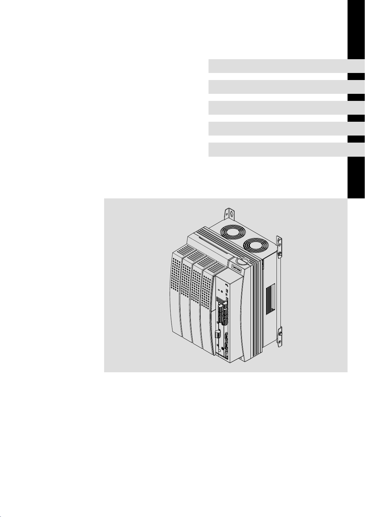
9300 vector 15 ... 30 kW
EVS9327−xV ... EVS9329−xV
Frequency inverter
Page 2
9300vec155
Page 3

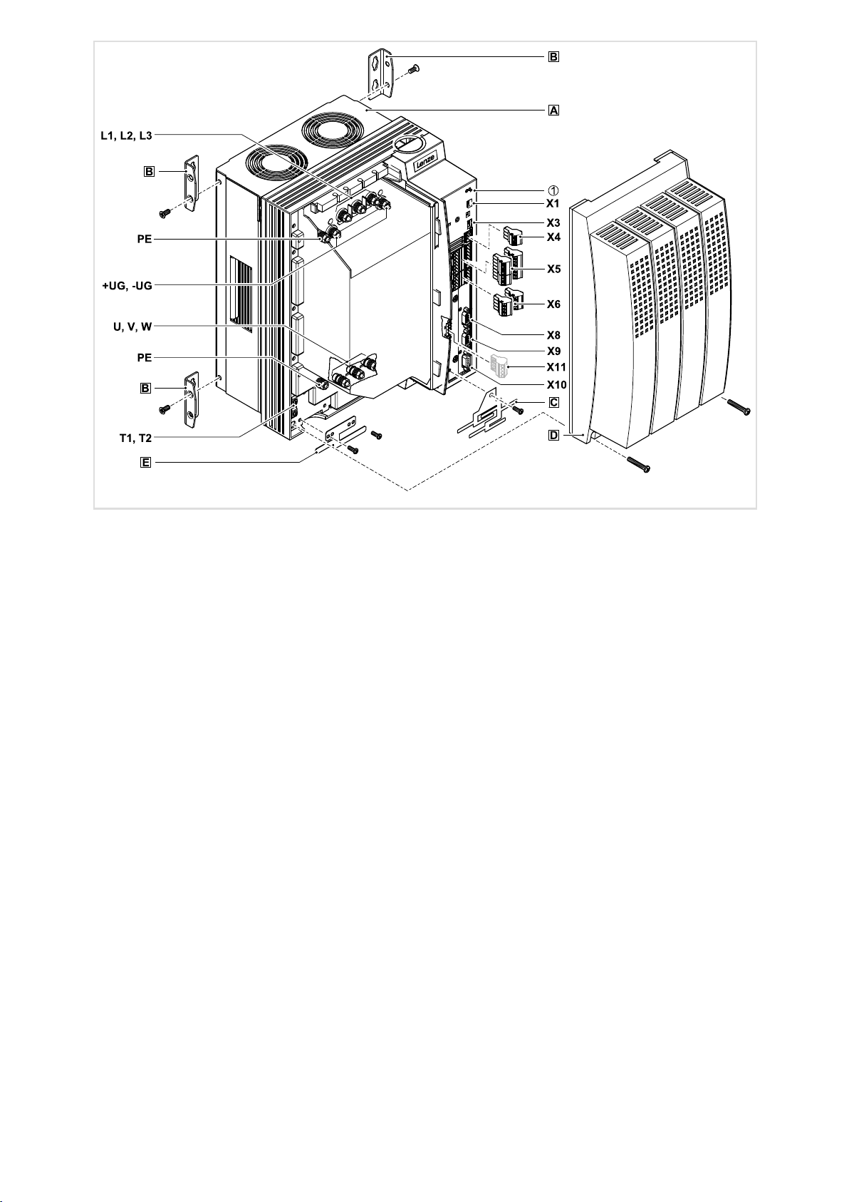
Key for overview
Position Description
Controller
Fixing bracket for standard mounting
EMC shield sheet with fixing screws for shielded control cables
Cover with fixing screws
EMC shield sheet for the motor cable and the feed cable for the motor temperature monitoring with PTC ther-
mistor or thermal contact (NC contact)
Interfaces and displays
Position Description
L1, L2, L3, PE Mains connection
+UG, −UG DC supply
U, V, W, PE Motor connection
T1, T2 Connection of PTC thermistor or thermal contact (NC contact) of the motor
X1 AIF interface (automation interface)
Slot for communication module (e. g. XT EMZ9371BC keypad)
X3 Jumper for setting analog input signal at X6/1, X6/2
X4 System bus (CAN) connection
X5 Connection of digital inputs and outputs
X6 Connection of analog inputs and outputs
X8 Connection of incremental encoder with TTL level or SinCos encoder and KTY temperature sensor of the motor
X9 Connection of digital frequency input signal
X10 Connection of digital frequency output signal
X11 Connection of KSR relay output for "safe standstill" (for variants V004 and V024 only)
Status displays
Position LED red LED green Operating status
Off On Controller is enabled
On On Mains is switched on and automatic start is inhibited
Off Blinking slowly Controller is inhibited
Off On Motor data identification is active
Blinking quickly Off Undervoltage or overvoltage
Blinking slowly Off Active fault
0Fig. 0Tab. 0
Page 4

Contentsi
1 About this documentation 5. . . . . . . . . . . . . . . . . . . . . . . . . . . . . . . . . . . . . . . . . . . . . . . . . .
1.1 Document history 5. . . . . . . . . . . . . . . . . . . . . . . . . . . . . . . . . . . . . . . . . . . . . . . . . . . .
1.2 Target group 5. . . . . . . . . . . . . . . . . . . . . . . . . . . . . . . . . . . . . . . . . . . . . . . . . . . . . . . .
1.3 Validity information 6. . . . . . . . . . . . . . . . . . . . . . . . . . . . . . . . . . . . . . . . . . . . . . . . . .
1.4 Conventions used 7. . . . . . . . . . . . . . . . . . . . . . . . . . . . . . . . . . . . . . . . . . . . . . . . . . . .
1.5 Notes used 8. . . . . . . . . . . . . . . . . . . . . . . . . . . . . . . . . . . . . . . . . . . . . . . . . . . . . . . . . .
2 Safety instructions 9. . . . . . . . . . . . . . . . . . . . . . . . . . . . . . . . . . . . . . . . . . . . . . . . . . . . . . . . .
2.1 General safety and application notes for Lenze controllers 9. . . . . . . . . . . . . . . . . .
2.2 Thermal motor monitoring 12. . . . . . . . . . . . . . . . . . . . . . . . . . . . . . . . . . . . . . . . . . . .
2.2.1 Forced ventilated or naturally ventilated motors 13. . . . . . . . . . . . . . . . . . .
2.2.2 Self−ventilated motors 14. . . . . . . . . . . . . . . . . . . . . . . . . . . . . . . . . . . . . . . . .
2.3 Residual hazards 16. . . . . . . . . . . . . . . . . . . . . . . . . . . . . . . . . . . . . . . . . . . . . . . . . . . . .
2.4 Safety instructions for the installation according to UL 18. . . . . . . . . . . . . . . . . . . . .
3 Parameter setting 20. . . . . . . . . . . . . . . . . . . . . . . . . . . . . . . . . . . . . . . . . . . . . . . . . . . . . . . . .
3.1 Parameter setting with the XT EMZ9371BC keypad 20. . . . . . . . . . . . . . . . . . . . . . . .
3.1.1 General data and operating conditions 20. . . . . . . . . . . . . . . . . . . . . . . . . .
3.1.2 Installation and commissioning 21. . . . . . . . . . . . . . . . . . . . . . . . . . . . . . . .
3.1.3 Display elements and function keys 21. . . . . . . . . . . . . . . . . . . . . . . . . . . . .
4 Troubleshooting and fault elimination 32. . . . . . . . . . . . . . . . . . . . . . . . . . . . . . . . . . . . . . .
3.1.4 Changing and saving parameters 23. . . . . . . . . . . . . . . . . . . . . . . . . . . . . . .
3.1.5 Loading a parameter set 25. . . . . . . . . . . . . . . . . . . . . . . . . . . . . . . . . . . . . . .
3.1.6 Transferring parameters to other standard devices 26. . . . . . . . . . . . . . . . .
3.1.7 Activating password protection 28. . . . . . . . . . . . . . . . . . . . . . . . . . . . . . . . .
3.1.8 Diagnostics 29. . . . . . . . . . . . . . . . . . . . . . . . . . . . . . . . . . . . . . . . . . . . . . . . . .
3.1.9 Menu structure 30. . . . . . . . . . . . . . . . . . . . . . . . . . . . . . . . . . . . . . . . . . . . . .
4.1 Display of operating data, diagnostics 32. . . . . . . . . . . . . . . . . . . . . . . . . . . . . . . . . . .
4.1.1 Display of operating data 32. . . . . . . . . . . . . . . . . . . . . . . . . . . . . . . . . . . . . .
4.1.2 Diagnostics 33. . . . . . . . . . . . . . . . . . . . . . . . . . . . . . . . . . . . . . . . . . . . . . . . . .
4.2 Troubleshooting 34. . . . . . . . . . . . . . . . . . . . . . . . . . . . . . . . . . . . . . . . . . . . . . . . . . . . .
4.2.1 Status display via controller LEDs 34. . . . . . . . . . . . . . . . . . . . . . . . . . . . . . . .
4.2.2 Fault analysis with the history buffer 35. . . . . . . . . . . . . . . . . . . . . . . . . . . .
4.3 Drive behaviour in the event of faults 36. . . . . . . . . . . . . . . . . . . . . . . . . . . . . . . . . . . .
4.4 Fault elimination 37. . . . . . . . . . . . . . . . . . . . . . . . . . . . . . . . . . . . . . . . . . . . . . . . . . . . .
4.4.1 Drive errors 37. . . . . . . . . . . . . . . . . . . . . . . . . . . . . . . . . . . . . . . . . . . . . . . . . .
4.4.2 Controller in clamp operation 38. . . . . . . . . . . . . . . . . . . . . . . . . . . . . . . . . . .
4.4.3 Behaviour in case of overvoltage in the DC bus (OU message) 39. . . . . . . .
4.5 System error messages 40. . . . . . . . . . . . . . . . . . . . . . . . . . . . . . . . . . . . . . . . . . . . . . . .
4.5.1 General error messages 40. . . . . . . . . . . . . . . . . . . . . . . . . . . . . . . . . . . . . . . .
4.5.2 Resetting system error messages 45. . . . . . . . . . . . . . . . . . . . . . . . . . . . . . . .
4
EDKVF93−02 EN 3.0
Page 5

1 About this documentation
Note!
This documentation contains all the information required by the machine
operator to run the drive controllers of the 9300 vector series installed in your
machine/system.
You may make further use of the information contained in this documentation
without asking Lenze for permission if you do not change the contents.
1.1 Document history
What is new / what has changed?
Material number Version Description
.MUw 3.0 11/2013 TD06 Error corrections
13217737 2.1 03/2010 TD23 Change of the company’s address
13217737 2.0 03/2010 TD14 New edition due to reorganisation of the company
13217737 1.0 07/2007 TD23 First edition
About this documentation
Document history
UL−warnings updated
Revision for software version 8x
1
Tip!
Information and auxiliary devices related to the Lenze products can be found
in the download area at
http://www.Lenze.com
1.2 Target group
This documentation is directed at qualified skilled personnel according to IEC 60364.
Qualified skilled personnel are persons who have the required qualifications to carry out
all activities involved in installing, mounting, commissioning, and operating the product.
EDKVF93−02 EN 3.0
5
Page 6
1
About this documentation
Validity information
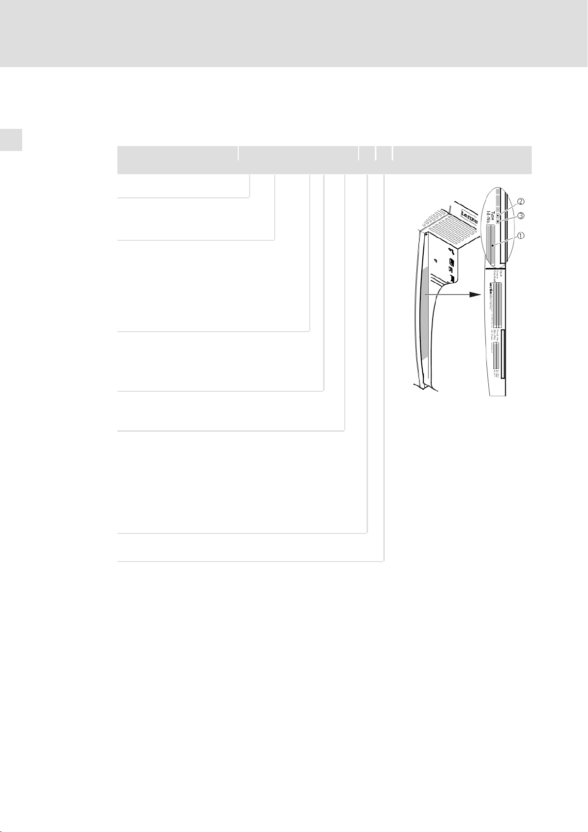
1.3 Validity information
... 9300 vector frequency inverters as of nameplate data:
Product series
EVF = Frequency inverter
Type no. / rated power
400V 480 V
9327 = 15 kW 18.5 kW
9328 = 22 kW 30 kW
9329 = 30 kW 37 kW
Type
E = Built−in unit
C = Built−in unit in "cold plate" technique
Nameplate
EVF 93xx ˘ x V Vxxx 1x 8x
Design
V = Vector−controlled frequency inverter
Variant
˘ Standard
V003 = In "cold plate" technique
V004 = With "safe standstill" function
V024 = With "safe standstill" function and for IT mains
V100 = For IT systems
Hardware version
Software version
9300vec112
6
EDKVF93−02 EN 3.0
Page 7

About this documentation
Conventions used
1
1.4 Conventions used
This documentation uses the following conventions to distinguish between different
types of information:
Type of information Identification Examples/notes
Spelling of numbers
Decimal separator language−dependentIn each case, the signs typical for the target
Warnings
UL warnings
UR warnings
Text
Program name » « PC software
Icons
Page reference Reference to another page with additional
Documentation reference Reference to another documentation with
language are used as decimal separators.
For example: 1234.56 or 1234,56
Given in English and French
For example: »Engineer«, »Global Drive
Control« (GDC)
information
For instance: 16 = see page 16
additional information
For example: EDKxxx = see
documentation EDKxxx
EDKVF93−02 EN 3.0
7
Page 8

1
About this documentation
Notes used
1.5 Notes used
The following pictographs and signal words are used in this documentation to indicate
dangers and important information:
Safety instructions
Structure of safety instructions:
Danger!
Pictograph and signal word Meaning
Danger!
Danger!
Stop!
(characterises the type and severity of danger)
Note
(describes the danger and gives information about how to prevent dangerous
situations)
Danger of personal injury through dangerous electrical voltage.
Reference to an imminent danger that may result in death or
serious personal injury if the corresponding measures are not
taken.
Danger of personal injury through a general source of danger.
Reference to an imminent danger that may result in death or
serious personal injury if the corresponding measures are not
taken.
Danger of property damage.
Reference to a possible danger that may result in property
damage if the corresponding measures are not taken.
Application notes
Pictograph and signal word Meaning
Note!
Tip!
Special safety instructions and application notes
Pictograph and signal word Meaning
Warnings!
Warnings!
Important note to ensure troublefree operation
Useful tip for simple handling
Reference to another documentation
Safety note or application note for the operation according to
UL or CSA requirements.
The measures are required to meet the requirements according
to UL or CSA.
8
EDKVF93−02 EN 3.0
Page 9

Safety instructions
General safety and application notes for Lenze controllers
2 Safety instructions
2.1 General safety and application notes for Lenze controllers
(in accordance with Low−Voltage Directive 2006/95/EC)
For your personal safety
Disregarding the following safety measures can lead to severe injury to persons and
damage to material assets:
ƒ Only use the product as directed.
ƒ Never commission the product in the event of visible damage.
ƒ Never commission the product before assembly has been completed.
ƒ Do not carry out any technical changes on the product.
ƒ Only use the accessories approved for the product.
2
ƒ Only use original spare parts from Lenze.
ƒ Observe all regulations for the prevention of accidents, directives and laws
applicable on site.
ƒ Transport, installation, commissioning and maintenance work must only be carried
out by qualified personnel.
– Observe IEC 364 and CENELEC HD 384 or DIN VDE 0100 and IEC report 664 or
DIN VDE 0110 and all national regulations for the prevention of accidents.
– According to this basic safety information, qualified, skilled personnel are persons
who are familiar with the assembly, installation, commissioning, and operation of
the product and who have the qualifications necessary for their occupation.
ƒ Observe all specifications in this documentation.
– This is the condition for safe and trouble−free operation and the achievement of
the specified product features.
– The procedural notes and circuit details described in this documentation are only
proposals. It is up to the user to check whether they can be transferred to the
particular applications. Lenze Automation GmbH does not accept any liability for
the suitability of the procedures and circuit proposals described.
ƒ Depending on their degree of protection, some parts of the Lenze controllers
(frequency inverters, servo inverters, DC speed controllers) and their accessory
components can be live, moving and rotating during operation. Surfaces can be hot.
– Non−authorised removal of the required cover, inappropriate use, incorrect
installation or operation, creates the risk of severe injury to persons or damage to
material assets.
– For more information, please see the documentation.
EDKVF93−02 EN 3.0
ƒ High amounts of energy are produced in the controller. Therefore it is required to
wear personal protective equipment (body protection, headgear, eye protection, ear
protection, hand guard).
9
Page 10

2
Safety instructions
General safety and application notes for Lenze controllers
Application as directed
Controllers are components which are designed for installation in electrical systems or
machines. They are not to be used as domestic appliances, but only for industrial purposes
according to EN 61000−3−2.
When controllers are installed into machines, commissioning (i.e. starting of the operation
as directed) is prohibited until it is proven that the machine complies with the regulations
of the EC Directive 2006/42/EC (Machinery Directive); EN 60204 must be observed.
Commissioning (i.e. starting of the operation as directed) is only allowed when there is
compliance with the EMC Directive (2004/108/EC).
The controllers meet the requirements of the Low−Voltage Directive 2006/95/EC. The
harmonised standard EN 61800−5−1 applies to the controllers.
The technical data and supply conditions can be obtained from the nameplate and the
documentation. They must be strictly observed.
Warning: Controllers are products which can be installed in drive systems of category C2
according to EN 61800−3. These products can cause radio interferences in residential areas.
In this case, special measures can be necessary.
Transport, storage
Please observe the notes on transport, storage, and appropriate handling.
Observe the climatic conditions according to the technical data.
Installation
The controllers must be installed and cooled according to the instructions given in the
corresponding documentation.
The ambient air must not exceed degree of pollution 2 according to EN 61800−5−1.
Ensure proper handling and avoid excessive mechanical stress. Do not bend any
components and do not change any insulation distances during transport or handling. Do
not touch any electronic components and contacts.
Controllers contain electrostatic sensitive devices which can easily be damaged by
inappropriate handling. Do not damage or destroy any electrical components since this
might endanger your health!
10
EDKVF93−02 EN 3.0
Page 11

Safety instructions
General safety and application notes for Lenze controllers
Electrical connection
When working on live controllers, observe the applicable national regulations for the
prevention of accidents (e.g. VBG 4).
The electrical installation must be carried out according to the appropriate regulations
(e.g. cable cross−sections, fuses, PE connection). Additional information can be obtained
from the documentation.
This documentation contains information on installation in compliance with EMC
(shielding, earthing, filter, and cables). These notes must also be observed for CE−marked
controllers. The manufacturer of the system is responsible for compliance with the limit
values demanded by EMC legislation. The controllers must be installed in housings (e.g.
control cabinets) to meet the limit values for radio interferences valid at the site of
installation. The housings must enable an EMC−compliant installation. Observe in
particular that e.g. the control cabinet doors have a circumferential metal connection to
the housing. Reduce housing openings and cutouts to a minimum.
Lenze controllers may cause a DC current in the PE conductor. If a residual current device
(RCD) is used for protection against direct or indirect contact for a controller with
three−phase supply, only a residual current device (RCD) of type B is permissible on the
supply side of the controller. If the controller has a single−phase supply, a residual current
device (RCD) of type A is also permissible. Apart from using a residual current device (RCD),
other protective measures can be taken as well, e.g. electrical isolation by double or
reinforced insulation or isolation from the supply system by means of a transformer.
2
Operation
If necessary, systems including controllers must be equipped with additional monitoring
and protection devices according to the valid safety regulations (e.g. law on technical
equipment, regulations for the prevention of accidents). The controllers can be adapted to
your application. Please observe the corresponding information given in the
documentation.
After the controller has been disconnected from the supply voltage, all live components
and power terminals must not be touched immediately because capacitors can still be
charged. Please observe the corresponding stickers on the controller.
All protection covers and doors must be shut during operation.
Safety functions
Certain controller versions support safety functions (e.g. "Safe torque off", formerly "Safe
standstill") according to the requirements of the EC Directive 2006/42/EC (Machinery
Directive). The notes on the integrated safety system provided in this documentation must
be observed.
Maintenance and servicing
The controllers do not require any maintenance if the prescribed operating conditions are
observed.
EDKVF93−02 EN 3.0
Disposal
Recycle metal and plastic materials. Ensure professional disposal of assembled PCBs.
The product−specific safety and application notes given in these instructions must be
observed!
11
Page 12

2
Safety instructions
Thermal motor monitoring
2.2 Thermal motor monitoring
Note!
From software version 8.1 onwards, the 9300 vector controllers are provided
with an I2xt function for sensorless thermal monitoring of the connected
motor.
2
ƒ I
xt monitoring is based on a mathematical model which calculates a
thermal motor utilisation from the detected motor currents.
ƒ The calculated motor utilisation is saved when the mains is switched off.
ƒ The function is UL−certified, i.e. additional protective measures for the motor
are not required in UL−approved systems.
ƒ Nevertheless, I
because other influences on the motor utilisation such as changes in the
cooling conditions (e.g. cooling air flow interrupted or too warm) cannot be
detected.
2
xt monitoring does not provide full motor protection
2
x t load of the motor is displayed in C0066.
Die I
The thermal loading capacity of the motor is expressed by the thermal motor time
constant (t, C0128). Find the value in the rated motor data or contact the manufacturer of
the motor.
2
x t monitoring has been designed such that it will be activated after 179 s in the
The I
event of a motor with a thermal motor time constant of 5 minutes (Lenze setting C0128),
a motor current of 1.5 x I
and a trigger threshold of 100 %.
N
Two adjustable trigger thresholds provide for different responses.
ƒ Adjustable response OC8 (TRIP, warning, off).
– The trigger threshold is set in C0127.
– The response is set in C0606.
– The response OC8, for instance, can be used for an advance warning.
ƒ Fixed response OC6−TRIP.
– The trigger threshold is set in C0120.
Behaviour of the I2 x t monitoring Condition
The I2 x t monitoring is deactivated.
C0066 is set = 0 % and
MCTRL−LOAD−I2XT is set = 0.00 %.
I2 x t monitoring is stopped.
The current value in C0066 and at the
MCTRL−LOAD−I2XT output is frozen.
I2 x t monitoring is deactivated.
The motor load is displayed in C0066.
When C0120 = 0 % and C0127 = 0 %, set controller
inhibit.
When C0120 = 0 % and C0127 = 0 %, set controller
enable.
Set C0606 = 3 (off) and C0127 > 0 %.
12
Note!
An error message OC6 or OC8 can only be reset if the I2 x t load falls below the
set trigger threshold by 5 %.
EDKVF93−02 EN 3.0
Page 13
Forced ventilated or naturally ventilated motors
2.2.1 Forced ventilated or naturally ventilated motors
Parameter setting
2
The following codes can be set for I
Code Meaning Value range Lenze setting
C0066 Display of the I2 x t load of the motor 0 ... 250 % −
C0120 Threshold: Triggering of error "OC6" 0 ... 120 % 0 %
C0127 Threshold: Triggering of error "OC8" 0 ... 120 % 0 %
C0128 Thermal motor time constant 0.1 ... 50.0 min 5.0 min
C0606 Response to error "OC8" TRIP, warning, off Warning
x t monitoring:
Calculate release time and I2xt load
Formula for release time Information
t +*(t) ln
ȡ
ȧ
ȧ
Ȣ
1 *
I
ȣ
z ) 1
I
Mot
ǒ
Ǔ
I
N
2
100
ȧ
ȧ
Ȥ
Mot
I
r
t Thermal motor time constant (C0128)
z Threshold value in C0120 (OC6) or C0127 (OC8)
Actual motor current (C0054)
Rated motor current (C0088)
Safety instructions
Thermal motor monitoring
2
Formulae for I2 x t load Information
L(t) Chronological sequence of the I2 x t load of the motor
2
I
Mot
ǒ
L(t) +
If the controller is inhibited, the I2 x t load is reduced:
Ǔ
100% ǒ1 * e
I
N
L(t) + L
Start
Ǹ
e
*t
t
t
*
t
I
Ǔ
Mot
Ir Rated motor current (C0088)
t Thermal motor time constant (C0128)
L
Start
(Display: C0066)
Actual motor current (C0054)
I2 x t load before controller inhibit
If an error is triggered, the value corresponds to the
threshold value set in C0120 (OC6) or
C0127 (OC8).
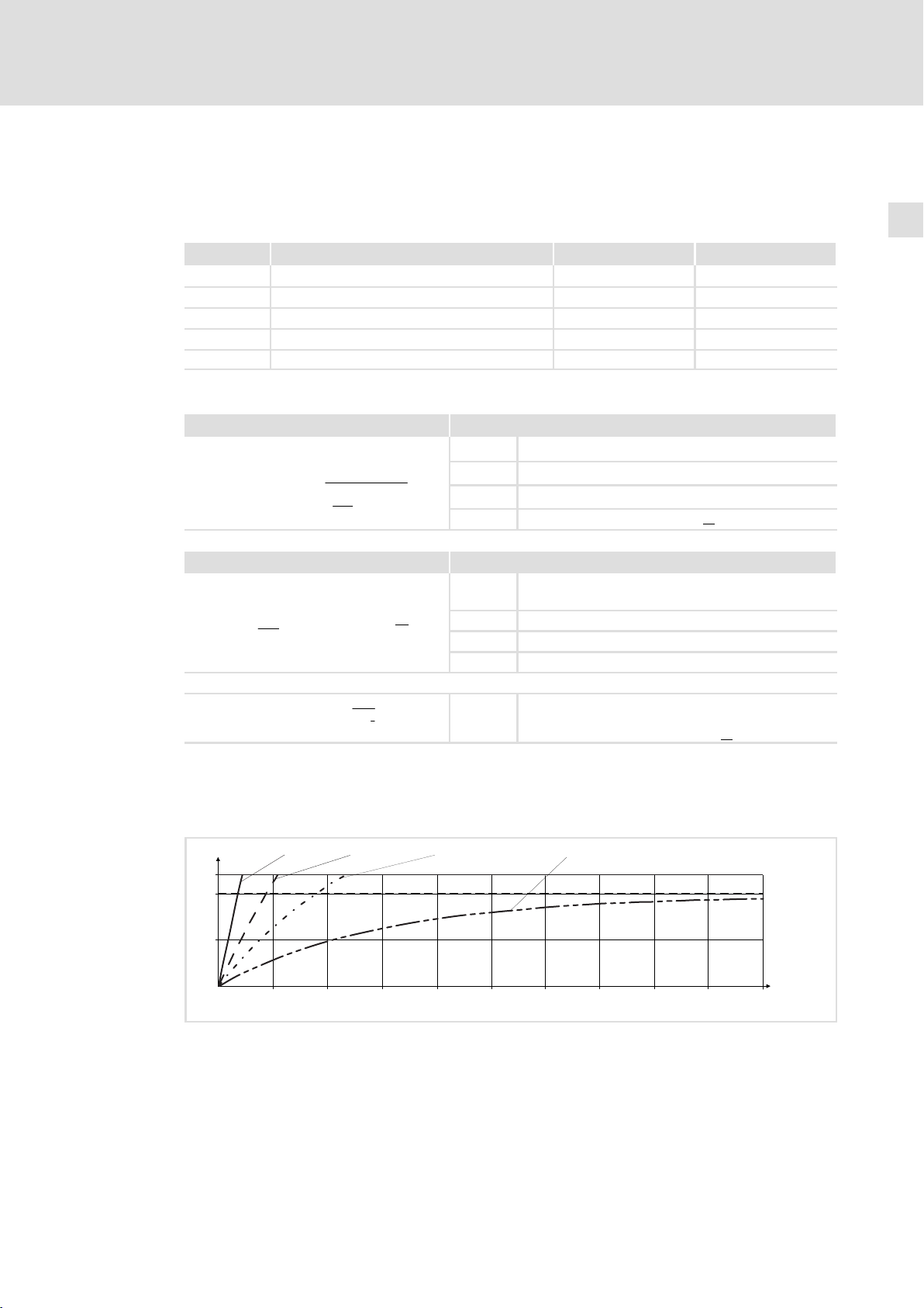
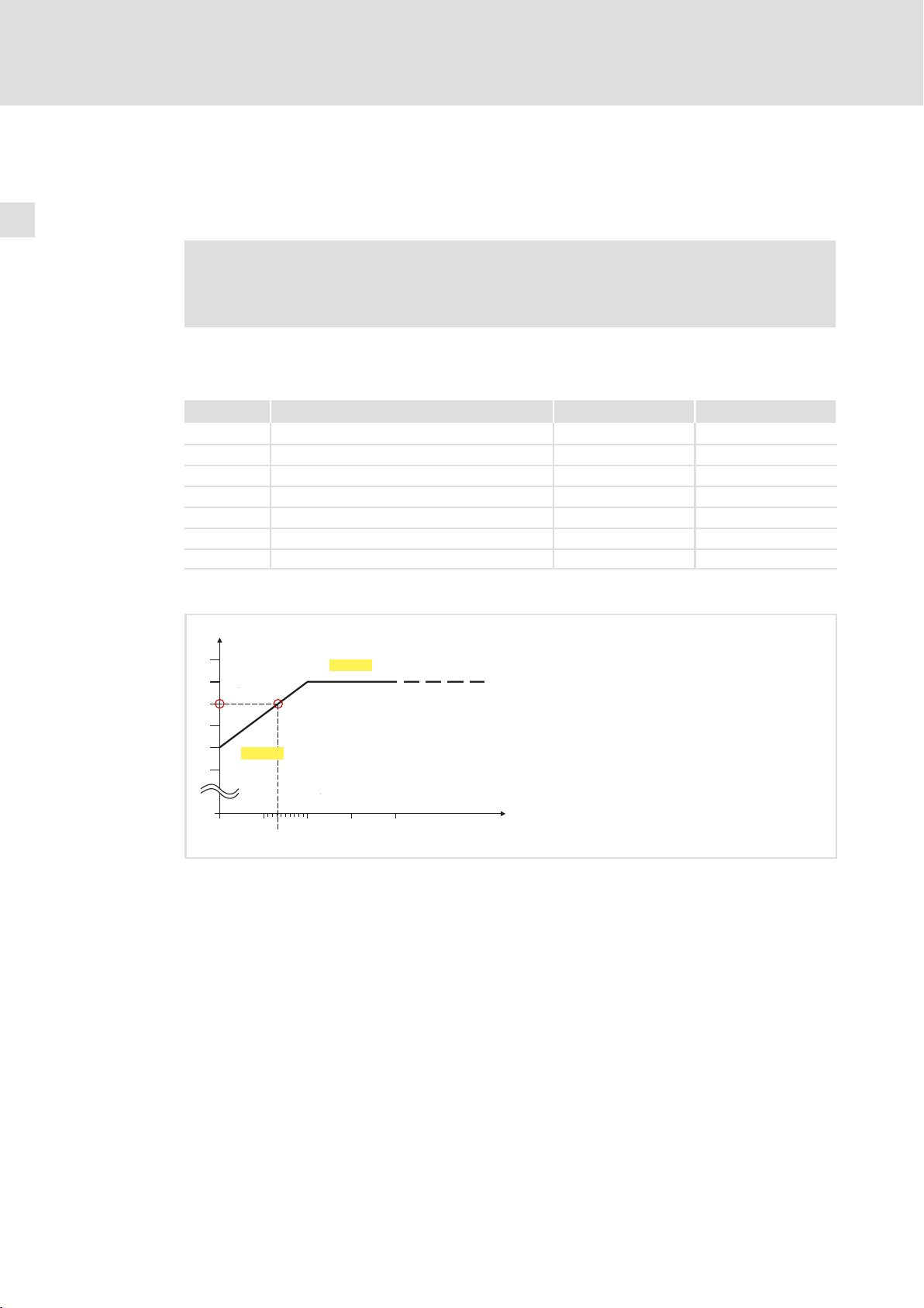
Read release time in the diagram
Diagram for detecting the release times for a motor with a thermal motor time constant
of 5 minutes (Lenze setting C0128):
L [%]
120
100
50
0
Fig. 2−1 I2 × t−monitoring: Release times for different motor currents and trigger thresholds
I = 3 × I
Mot N
0 100 200 300 400 500 600 700 800 900
I
Mot
I
r
LI
T Time
I = 2 × I
Mot N
Actual motor current (C0054)
Rated motor current (C0088)
2
x t load of the motor (display: C0066)
I = 1.5 × I
Mot N
I = 1 × I
Mot N
t [s]
1000
9300STD105
EDKVF93−02 EN 3.0
13
Page 14
2
Safety instructions
Thermal motor monitoring
Self−ventilated motors
2.2.2 Self−ventilated motors
Due to the construction, self−ventilated standard motors are exposed to an increased heat
generation in the lower speed range compared to forced ventilated motors.
Warnings!
For complying with the UL 508C standard, you have to set the
speed−dependent evaluation of the permissible torque via code C0129/x.
Parameter setting
The following codes can be set for I
Code Meaning Value range Lenze setting
C0066 Display of the I2 x t load of the motor 0 ... 250 % −
C0120 Threshold: Triggering of error "OC6" 0 ... 120 % 0 %
C0127 Threshold: Triggering of error "OC8" 0 ... 120 % 0 %
C0128 Thermal motor time constant 0.1 ... 50.0 min 5.0 min
C0606 Response to error "OC8" TRIP, warning, off Warning
C0129/1 S1 torque characteristic I1/I
C0129/2 S1 torque characteristics n2/n
2
x t monitoring:
rated
rated
10 ... 200 % 100 %
10 ... 200 % 40 %
Effect of code C0129/x
I / I
N
1.1
1.0
3
0.9
0.8
0.7
0
0.6
0
0 0.1
Fig. 2−2 Working point in the range of characteristic lowering
2
C0129/1
0.132
C0129/2
1
0.2 0.3 0.4
n / n
N
9300STD350
The lowered speed / torque characteristic (Fig. 2−2) reduces the permissible thermal load
of self−ventilated standard motors. The characteristic is a line the definition of which
requires two points:
ƒ Point : Definition with C0129/1
This value also enables an increase of the maximally permissible load.
ƒ Point : Definition with C0129/2
With increasing speeds, the maximally permissible load remains unchanged
(I
Mot
= I
rated
).
In Fig. 2−2, the motor speed and the corresponding permissible motor torque () can be
read for each working point (on the characteristic () ... ). can also be calculated
using the values in C0129/1and C0129/2 (evaluation coefficient "y", 15).
14
EDKVF93−02 EN 3.0
Page 15

Thermal motor monitoring
Calculate release time and I2xt load
Calculate the release time and the I
2
x t load of the motor considering the values in
C0129/1 and C0129/2(evaluation coefficient "y").
Formulae for release time Information
T Release time of the I2 x t monitoring
ȡ
I
Mot
ǒ
y I
Ǹ
e
z ) 1
Ǔ
N
n
) C0129ń1
n
N
*
T +*(t) ln
ȧ
ȧ
1 *
Ȣ
100% * C0129ń1
y +
Formulae for I2 x t load Information
If the controller is inhibited, the I2 x t load is reduced:
L(t) +
C0129ń2
I
Mot
ǒ
y I
L(t) + L
2
Ǔ
100% ǒ1 * e
N
Start
2
100
t
t
ȣ
t Thermal motor time constant (C0128)
In Function: Natural logarithm
ȧ
ȧ
I
Mot
Ȥ
I
r
z Threshold value in C0120 (OC6) or C0127 (OC8)
y Evaluation coefficient
n
rated
L(t) Chronological sequence of the I2 x t load of the motor
y Evaluation coefficient
*t
Ǔ
t
I
Mot
Ir Rated motor current (C0088)
t Thermal motor time constant (C0128)
L
Start
Actual motor current (C0054)
Rated motor current (C0088)
Rated speed (C0087)
(Display: C0066)
Actual motor current (C0054)
I2 x t load before controller inhibit
If an error is triggered, the value corresponds to the
threshold value set in C0120 (OC6) or
Safety instructions
Self−ventilated motors
C0127 (OC8).
2
EDKVF93−02 EN 3.0
15
Page 16

2
2.3 Residual hazards
Safety instructions
Residual hazards
Protection of persons
ƒ Before working on the controller, check that no voltage is applied to the power
terminals:
– Because the power terminals V, W, +U
after disconnecting from mains.
– Because the power terminals L1, L2, L3; U, V, W, +U
motor is stopped.
ƒ The leakage current to earth (PE) is >3.5 mA. According to EN 61800−5−1
– a fixed installation is required,
– a double PE connection is required, or, if there is only a single PE connection, the PE
conductor must have a cross−section of at least 10 mm
ƒ The heat sink of the controller has an operating temperature of > 80 °C:
– Contact with the heatsink results in burns.
and −UG remain live for at least 3 minutes
G
and −UG remain live when the
G
2
.
ƒ If you use the "flying−restart circuit" function (C0142 = 2, 3) for machines with a low
moment of inertia and minimum friction:
– After controller enable in standstill, the motor may start or change its direction of
rotation for a short time, because the flying restart process also is carried out at a
speed of 0.
ƒ During parameter set transfer, the control terminals of the controller can have
undefined states!
– Therefore the plugs X5 and X6 must be unplugged, before the transfer is executed.
This ensures that the controller is inhibited and all control terminals have the
defined "LOW" state.
Device protection
ƒ Frequent mains switching (e.g. inching mode via mains contactor) can overload and
destroy the input current limitation of the drive controller:
– At least 3 minutes must pass between switching off and restarting the devices
EVS9321−xS and EVS9322−xS.
– At least 3 minutes must pass between two starting procedures of the devices
EVS9323−xS ... EVS9332−xS.
– Use the "safe torque off" safety function (STO) if safety−related mains
disconnections occur frequently. The drive variants Vxx4 are equipped with this
function.
16
Motor protection
ƒ Certain drive controller settings can overheat the connected motor:
– E. g. long−time operation of the DC injection brake.
– Long−time operation of self−ventilated motors at low speeds.
EDKVF93−02 EN 3.0
Page 17

Safety instructions
Residual hazards
Protection of the machine/system
ƒ Drives can reach dangerous overspeeds (e. g. setting of high output frequencies in
connection with motors and machines not suitable for this purpose):
– The drive controllers do not provide protection against such operating conditions.
For this purpose, use additional components.
2
EDKVF93−02 EN 3.0
17
Page 18

2
Safety instructions
Safety instructions for the installation according to UL
2.4 Safety instructions for the installation according to UL
Original − English
Warnings!
ƒ Motor Overload Protection
– For information on the protection level of the internal overload protection
for a motor load, see the corresponding manuals or software helps.
– If the integral solid state motor overload protection is not used, external or
remote overload protection must be provided.
ƒ Branch Circuit Protection
– The integral solid state protection does not provide branch circuit
protection.
– Branch circuit protection has to be provided externally in accordance with
corresponding instructions, the National Electrical Code and any
additional codes.
ƒ Please observe the specifications for fuses and screw−tightening torques in
these instructions.
ƒ EVS9327 EVS9329:
– Suitable for use on a circuit capable of delivering not more than 5000 rms
symmetrical amperes, 480 V maximum, when protected by fuses.
– Suitable for use on a circuit capable of delivering not more than 50000 rms
symmetrical amperes, 480 V maximum, when protected by J, T or R class
fuses.
– Maximum surrounding air temperature: 0 ... +50 °C
– > +40 °C: reduce the rated output current by 2.5 %/°C
– Use 60/75 °C or 75 °C copper wire only.
18
EDKVF93−02 EN 3.0
Page 19

Original − French
Warnings!
ƒ Protection du moteur contre les surcharges
– Pour obtenir des informations sur le niveau de protection offert par la
protection intégrée contre les surcharges du moteur, se reporter aux
manuels correspondants ou aux systèmes d’aide logiciels.
– Si la protection statique intégrée contre les surcharges du moteur n’est
pas utilisée, prévoir impérativement un dispositif de protection externe ou
séparé contre les surcharges.
ƒ Protection par disjoncteur
– La protection statique intégrée n’offre pas la même protection qu’un
disjoncteur.
– Une protection par disjoncteur externe doit être fournie, conformément
aux indications fournies, au National Electrical Code et aux autres
dispositions applicables.
ƒ Se conformer aux spécifications relatives aux fusibles et aux couples de
serrage contenues dans le présent document.
ƒ EVS9327 EVS9329 :
– Convient aux circuits non susceptibles de délivrer plus de 5000 ampères
symétriques eff., maximum 480 V, avec protection par fusibles.
– Convient aux circuits non susceptibles de délivrer plus de 50000 ampères
symétriques eff., maximum 480 V, avec protection par des fusibles de
calibre J, T ou R.
– Température ambiante maximale : 0 ... +50 °C
– > +40 °C: ramener le courant assigné de sortie à 2,5 %/°C
– Utiliser exclusivement des conducteurs en cuivre 60/75 °C ou 75 °C.
Safety instructions
Safety instructions for the installation according to UL
2
EDKVF93−02 EN 3.0
19
Page 20

3
Parameter setting
Parameter setting with the XT EMZ9371BC keypad
General data and operating conditions
3 Parameter setting
3.1 Parameter setting with the XT EMZ9371BC keypad
Description
The keypad is available as an accessory. A full description of the keypad can be obtained
from the Instructions included in the keypad delivery.
Plugging in the keypad
It is possible to plug the keypad into the AIF interface or remove it during operation.
As soon as the keypad is supplied with voltage, it carries out a self−test. The keypad is ready
for operation if it is in display mode.
3.1.1 General data and operating conditions
dABbc
Menu
p
SHPRG
Code
Para
0
b
MCTRL-NOUT
z
YZ
0050
50.00_Hz
T
V
00
y
S
U
ca
Feature Values
Dimensions
Width a 60 mm
Height b 73.5 mm
Depth c 15 mm
Environmental conditions
Climate
Storage IEC/EN 60721−3−1 1K3 (−25 ... +60 °C)
Transport IEC/EN 60721−3−2 2K3 (−25 ... +70 °C)
Operation IEC/EN 60721−3−3 3K3 (−10 ... +60 °C)
9371BC011
Enclosure IP 20
20
EDKVF93−02 EN 3.0
Page 21

Parameter setting with the XT EMZ9371BC keypad
dABbc
0
1
2
3
3.1.2 Installation and commissioning
E82ZWLxxx
00
ABbc
50
00
enu
M
e
od
0_
C
ra
a
p
P
d
G
R
0.0
P
H
5
S
MCTRL-NOUT
T
z
S
YZ
y
EMZ9371BC
00
Hz
V
U
dABbc
Menu
p
SHPRG
Code
0050
Para
GLOBAL DRIVE
Init
z
T
V
YZ
y
S
U
dABbc
Menu
p
SHPRG
Code
Para
50.00_Hz
MCTRL-NOUT
z
YZ
y
E82ZBBXC
Parameter setting
3
Installation and commissioning
00
0050
T
V
S
U
d
z
YZ
y
d
z
YZ
y
0050
50.00 Hz
T
S
0050
50.00 Hz
T
S
00
20 %
V
U
00
20 %
V
U
Fig. 3−1 Installation and commissioning of XT EMZ9371BC keypad or E82ZBBXC diagnosis terminal
Connect keypad to the AIF interface on the front of the standard device.
The keypad can be connected/disconnected during operation.
As soon as the keypad is supplied with voltage, it carries out a short self−test.
The operation level indicates when the keypad is ready for operation:
Current state of the standard device
Memory location 1 of the user menu (C0517):
Code number, subcode number, and current value
Active fault message or additional status message
Actual value in % of the status display defined in C0004
must be pressed to leave the operation level
3.1.3 Display elements and function keys
9371BC018
EDKVF93−02 EN 3.0
0
1
2
3
dABbc
Menu
p
SHPRG
Code
0050
Para
50.00_Hz
MCTRL-NOUT
z
YZ
T
00
V
4
5
6
7
8
y
S
U
9371BC002
Fig. 3−2 Display elements and function keys of the XT EMZ9371BC keypad
21
Page 22

3
Parameter setting
Parameter setting with the XT EMZ9371BC keypad
Display elements and function keys
Displays
Status displays of standard device
Display Meaning Explanation
Acceptance of the parameters
Display Meaning Explanation
Parameter is accepted immediately Standard device operates immediately with
SHPRG Parameter must be acknowledged with Standard device operates with the new
SHPRG Parameter must be acknowledged in case of
None Display parameter Change is not possible
Active level
Display Meaning Explanation
Menu Menu level is active Select main menu and submenus
Code Code level is active Select codes and subcodes
Para Parameter level is active Change parameters in the codes or
None Operating level is active Display operating parameters
Short text
Display Meaning Explanation
alphanumericalContents of the menus, meaning of the codes
Number
Active level Meaning Explanation
Menu level Menu number Display is only active for operation with
Code level Four−digit code number
Number
Active level Meaning Explanation
Menu level Submenu number Display is only active for operation with
Code level Two−digit subcode number
Parameter value
Cursor
Function keys
Ready for operation
Pulse inhibit is active Power outputs are inhibited
The set current limit is exceeded in motor or
generator mode
Speed controller 1 in the limitation Drive is torque−controlled
(Only active for operation with standard
devices of the 9300 series)
Active fault
the new parameter value
parameter value after being acknowledged
controller inhibit
and parameters
In the operating level display of C0004 in % and
the active fault
Parameter value with unit
In the parameter level, the digit above the cursor can be directly changed
For description see the following table
Standard device operates with the new
parameter value after the controller is
enabled again
subcodes
standard devices of the 8200 vector or 8200
motec series
standard devices of the 8200 vector or 8200
motec series
22
EDKVF93−02 EN 3.0
Page 23

Function keys
Note!
Shortcuts with :
Press and hold , then press the second key in addition.
Parameter setting
Parameter setting with the XT EMZ9371BC keypad
Changing and saving parameters
3
Key
Menu level Code level Parameter level Operating level
Go to the "Short setup"
!
!
"
#
$
%
1)
menu and load
predefined
configurations
Change between menu
items
Quick change between
menu items
Change between main menu, submenu and code
level
Deactivate the function of the key %, the LED in the key goes off
Inhibit the controller, the LED in the key is lit.
Reset fault (TRIP−Reset): 1. Remove the cause of malfunction
Only active for operation with standard devices of the 8200 vector or 8200 motec series
1)
Change to the
parameter level
Change of code number
Quick change of code
number
2. Press %
3. Press $
3.1.4 Changing and saving parameters
Function
Change to the operating
level
Accept parameters
when SHPRG or
SHPRG is displayed
Change of digit via
cursor
Quick change of digit
via cursor
Cursor to the right
Cursor to the left
Change to the code
level
Note!
Your settings have an effect on the current parameters in the main memory.
You must save your settings in a parameter set so that they are not lost when
the mains are connected.
If you only need one parameter set, save your settings as parameter set 1,
since parameter set 1 is loaded automatically after mains connection.
Step Key
1. Select the menu ! " # Use the arrow keys to select the desired menu
2. Change to the code level " Display of the first code in the menu
3. Select code or subcode ! Display of the current parameter value
4. Change to the parameter level
5. When SHPRG is displayed, inhibit the
controller
6. Change parameter
sequence
1)
%
A " # Move cursor below the digit to be changed
B ! Change of digit
!
Action
The drive coasts
Quick change of digit
EDKVF93−02 EN 3.0
23
Page 24

3
Parameter setting
Parameter setting with the XT EMZ9371BC keypad
Changing and saving parameters
Step
7. Accept the changed parameter
Display of SHPRG or SHPRG Confirm change to accept the parameter
Display − The parameter has been accepted immediately
8. Enable the controller, if required $
9. Change to the code level
10. Change further parameters Restart the "loop" with step 1. or 3.
11. Save changed parameters
Select the parameter set in which
the parameters are to be saved
permanently
12.
Change to the code level
13. Set parameters for another parameter
set
1)
The function of the % key can be programmed:
C0469 = 1: Controller inhibit
C0469 = 2: Quick stop (Lenze setting)
sequence
1)
A Display of the operating level
B Display of the code with changed parameter
A ! " # Select the code C0003 "PAR SAVE" in the menu
B Change to the parameter level
C Save as parameter set 1:
D When "OK" is displayed, the settings are permanently
A Display of the operating level
B Display of C0003 "PAR SAVE"
ActionKey
Display "OK"
The drive runs again
"Load/Store"
Display "0" and "READY"
ð Set "1" "Save PS1"
Save as parameter set 2:
ð Set "2" "Save PS2"
Save as parameter set 3:
ð Set "3" "Save PS3"
Save as parameter set 4:
ð Set "4" "Save PS4"
saved in the selected parameter set.
Restart the "loop" with step 1. or 3.
24
EDKVF93−02 EN 3.0
Page 25

Parameter setting
Parameter setting with the XT EMZ9371BC keypad
Loading a parameter set
3
3.1.5 Loading a parameter set
The keypad serves to load a saved parameter set into the main memory when the controller
is inhibited. After the controller is enabled, it operates with the new parameters.
Danger!
ƒ When a new parameter set is loaded, the controller is reinitialised and acts
as if it had been connected to the mains:
– System configurations and terminal assignments can be changed. Make
sure that your wiring and drive configuration comply with the settings of
the parameter set.
ƒ Only use terminal X5/28 as source for the controller inhibit! Otherwise the
drive may start in an uncontrolled way when switching over to another
parameter set.
Note!
ƒ After switching on the supply voltage, the controller always loads parameter
set 1 into the main memory.
ƒ It is also possible to load other parameter sets into the main memory via the
digital inputs or bus commands.
Step Key
1. Inhibit controller Terminal X5/28 = LOW
2. Load the saved parameter set into the
main memory
Select the parameter set to be
loaded
3.
Change to the code level
4. Enable controller Terminal X5/28 = HIGH
sequence
A ! " # Select the code C0002 "PAR LOAD" in the menu
B Change to the parameter level
C Load parameter set 1:
D "RDY" goes off. The parameter set is loaded completely
A Display of the operating level
B Display of C0002 "PAR LOAD"
Action
"Load/Store"
The active parameter set is displayed, e. g. display "0"
and "Load Default"
If you want to restore the delivery status, proceed with
D
ð Set "1" "Load PS1"
Load parameter set 2:
ð Set "2" "Load PS2"
Load parameter set 3:
ð Set "3" "Load PS3"
Load parameter set 4:
ð Set "4" "Load PS4"
into the main memory if "RDY" is displayed again.
The drive is running with the settings of the loaded
parameter set
EDKVF93−02 EN 3.0
25
Page 26

3
Parameter setting
Parameter setting with the XT EMZ9371BC keypad
Transferring parameters to other standard devices
3.1.6 Transferring parameters to other standard devices
Parameter settings can be easily copied from one standard device to another by using the
keypad.
For this purpose use the "Load/Store" menu
Danger!
During the parameter transfer from the keypad to the standard device the
control terminals can adopt undefined states!
Therefore the plugs X5 and X6 must be disconnected from the standard device
before the transfer takes place. This ensures that the controller is inhibited and
all control terminals have the defined state "LOW".
Copying parameter sets from the standard device into the keypad
Note!
After copying the parameter sets into the XT keypad (C0003 = 11), always the
parameter set that was loaded last via C0002 is activated.
Like this the current parameters also remain active after copying:
ƒ Save the current parameters in the parameter set before copying and load
this parameter set in the controller via C0002.
Step Key
1. Connect the keypad to standard
device 1
2. Inhibit controller Terminal X5/28 = LOW
3. Select C0003 in the "Load/Store"
menu
4. Change to the parameter level
5. Copy all parameter set into the
keypad
6. Start copying
7.
Change to the code level
8. Enable controller Terminal X5/28 = HIGH
9. Remove keypad from standard device
1
A
B
sequence
!"#
Action
The drive coasts.
Select code C0003 "PAR SAVE" in the "Load/Store"
menu using the arrow keys.
Display "0" and "READY"
The settings saved in the keypad are overwritten.
Set "11" "Save extern"
The "RDY" status display goes off. As parameter value
"BUSY" is displayed.
If "BUSY" goes off after approx. one minute, all
parameter sets were copied into the keypad. The
"RDY" status display is lit.
Display of the operating level
Display C0003 and "PAR SAVE"
26
EDKVF93−02 EN 3.0
Page 27

Parameter setting
Parameter setting with the XT EMZ9371BC keypad
Transferring parameters to other standard devices
Copying parameter sets fom keypad into the standard device
3
Step Key
1. Connect the keypad to standard
device 2
2. Inhibit controller Terminal X5/28 = LOW
3. Pull the plugs X5 and X6 All control terminals have the defined "LOW" status.
4. Select C0002 in the "Load/Store"
menu
5. Change to the parameter level
6. Select the correct copy function The settings saved in the standard device are
l Copy all parameter sets available into the
EEPROM of the standard device and save them
permanently.
l Copy individual parameter sets into the main
memory of the standard device.
7. Start copying
8.
Change to the code level
9. l If the function "Copy all parameter
sets into the EEPROM"
(C0002 = 20) is selected, they
might have to be loaded in the
main memory manually.
l If the function "Copy individual
parameter sets into the main
memory" (C0002 = 1x) is selected,
they might have to be saved
permanently in the EEPROM
manually.
10. Plug in plugs X5 and X6
11. Enable controller Terminal X5/28 = HIGH
A
B
sequence
!"#
!"#
Action
The "IMP" status display is it.
The drive coasts
Select code C0002 "PAR LOAD" in the "Load/Store"
menu using the arrow keys.
The active parameter set is shown, e. g. display "0" and
"Load Default"
overwritten.
l The parameter set that was active before copying is
overwritten.
l The parameters are not yet active after copying.
Select parameter set and load it in the main
memory. 25
Set "20" "ext −> EEPROM"
Copy parameter set 1 into the main memory:
Set ð "11" "Load ext PS1"
Copy parameter set 2 into the main memory:
Set ð "12" "Load ext PS2"
Copy parameter set 3 into the main memory:
Set ð "13" "Load ext PS3"
Copy parameter set 4 into the main memory:
Set ð "14" "Load ext PS4"
The "RDY" status display goes off. As parameter value
"BUSY" is displayed.
If "BUSY" goes off, the parameter sets selected were
copied into the standard device. The "RDY" status
display is lit.
Display of the operating level
Display C0002 and "PAR LOAD"
Select code C0003 "PAR SAVE" in the "Load/Store"
menu using the arrow keys and store the contents of
the main memory permanently.
The drive is running with the new settings.
EDKVF93−02 EN 3.0
27
Page 28

3
Parameter setting
Parameter setting with the XT EMZ9371BC keypad
Activating password protection
3.1.7 Activating password protection
Note!
ƒ If the password protection is activated (C0094 = 1 ... 9999), you only have
free access to the user menu.
ƒ To access the other menus, you must enter the password. By this, the
password protection is annulled until you enter a new password.
ƒ Please observe that the password−protected parameters can be overwritten
as well when transferring the parameter sets to other standard devices. The
password is not transferred.
ƒ Do not forget your password! If you have forgotten your password, it can
only be reset via a PC or a bus system!
Activate password protection
Step Key
sequence
1. Select the "USER menu" ! " # Change to the user menu using the arrow keys
2. Change to the code level " Display of code C0051 "MCTRL−NACT"
3. Select C0094 Display of code C0094 "Password"
4. Change to the parameter level Display "0" = no password protection
5. Set password
A Select password (1 ... 9999)
B Confirm password
6. Change to the code level
A Display of the operating level
B Display of C0094 and "Password"
7. Change to the "USER menu" # # !
The password protection is active now.
You can only quit the user menu if you re−enter the password and confirm it with
Action
.
Remove password protection
Step Key
1. Change to the code level in the user
menu
2. Select C0094 Display of code C0094 "Password"
3. Change to the parameter level Display "9999" = password protection is active
4. Enter password
5. Change to the code level
The password protection is deactivated now. All menus can be freely accessed again.
sequence
"
A ! Set valid password
B Confirm
A Display of the operating level
B Display of C0094 and "Password"
Action
The password protection is deactivated by entering the
password once again.
28
EDKVF93−02 EN 3.0
Page 29

3.1.8 Diagnostics
In the "Diagnostic" menu the two submenus "Actual info" and "History" contain all codes
for
ƒ monitoring the drive
ƒ fault/error diagnosis
In the operating level, more status messages are displayed. If several status messages are
active, the message with the highest priority is displayed.
Priority Display Meaning
1 GLOBAL DRIVE INIT Initialisation or communication error between
2 XXX − TRIP Active TRIP (contents of C0168/1)
3 XXX − MESSAGE Active message (contents of C0168/1)
4
Special device states:
5
Source for controller inhibit (the value of C0004 is displayed simultaneously):
STP1
STP3 Operating module or LECOM A/B/LI
STP4 INTERBUS or PROFIBUS−DP
STP5
STP6 C0040
6
Source for quick stop (QSP):
QSP−term−Ext The MCTRL−QSP input of the MCTRL function block is on HIGH signal.
QSP−C0135 Operating module or LECOM A/B/LI
QSP−AIF INTERBUS or PROFIBUS−DP
QSP−CAN
7 XXX − WARNING Active warning (contents of C0168/1)
8 xxxx Value below C0004
Parameter setting
Parameter setting with the XT EMZ9371BC keypad
Diagnostics
keypad and controller
Switch−on inhibit
9300 servo: Terminal X5/28
ECSxS/P/M/A: Terminal X6/SI1
9300 servo, ECSxA/E: System bus (CAN)
ECSxS/P/M: MotionBus (CAN)
9300 servo, ECSxA: System bus (CAN)
ECSxS/P/M: MotionBus (CAN)
3
EDKVF93−02 EN 3.0
29
Page 30

3
Parameter setting
Parameter setting with the XT EMZ9371BC keypad
Menu structure
3.1.9 Menu structure
For simple, user−friendly operation, the codes are clearly arranged in function−related
menus:
Main menu Submenus Description
Display Display
User−Menu Codes defined in C0517
Code list All available codes
ALL All available codes listed in ascending order (C0001 ... C7999)
PS 1 Codes in parameter set 1 (C0001 ... C1999)
PS 2 Codes in parameter set 2 (C2001 ... C3999)
PS 3 Codes in parameter set 3 (C4001 ... C5999)
PS 4 Codes in parameter set 4 (C6001 ... C7999)
Load/Store Parameter set management
Diagnostic Diagnostic
Actual info Display codes to monitor the drive
History Fault analysis with history buffer
Short setup Quick configuration of predefined applications
Parameter set transfer, restore delivery status
Configuration of the user menu
The predefined applications depend on the type of the standard device (frequency
inverter, servo inverter, position controller, ...)
Main FB Configuration of the main function blocks
NSET Setpoint processing
NSET−JOG Fixed setpoints
NSET−RAMP1 Ramp function generator
MCTRL Motor control
DFSET Digital frequency processing
DCTRL Internal control
Terminal I/O Connection of inputs and outputs with internal signals
AIN1 X6.1/2 Analog input 1
AIN2 X6.3/4 Analog input 2
AOUT1 X6.62 Analog output 1
AOUT2 X6.63 Analog output 2
DIGIN Digital inputs
DIGOUT Digital outputs
DFIN Digital frequency input
DFOUT Digital frequency output
State bus State bus (not with 9300 frequency inverter)
Controller Configuration of internal control parameters
Speed Speed controller
Current Current controller or torque controller
Phase Phase controller (not with 9300 frequency inverter)
Motor/Feedb. Input of motor data, configuration of speed feedback
Motor adj Motor data
Feedback Configuration of feedback systems
Monitoring Configuration of monitoring functions
30
EDKVF93−02 EN 3.0
Page 31

Parameter setting
Parameter setting with the XT EMZ9371BC keypad
Menu structure
DescriptionSubmenusMain menu Description
DisplayDisplay
LECOM/AIF Configuration of operation with communication modules
LECOM A/B Serial interface
AIF interface Process data
Status word Display of status words
System bus Configuration of system bus (CAN)
Management CAN communication parameters
CAN−IN1
CAN−OUT1
CAN−IN2
CAN−OUT2
CAN−IN3
CAN−OUT3
Status word Display of status words
FDO Free digital outputs
Diagnostic CAN diagnostic
FB config Configuration of function blocks
CAN object 1
CAN object 2
CAN object 3
3
Func blocks Parameterisation of function blocks
The submenus contain all available function blocks
FCODE Configuration of free codes
Identify Identification
Drive Software version of standard device
Op Keypad Software version of keypad
EDKVF93−02 EN 3.0
31
Page 32

4
Troubleshooting and fault elimination
Display of operating data, diagnostics
Display of operating data
4 Troubleshooting and fault elimination
4.1 Display of operating data, diagnostics
4.1.1 Display of operating data
Description
Important operating parameters are measured by the controller. They can be displayed
with the keypad or PC.
Some operating data can be calibrated to be displayed or selected directly with the unit of
the process quantity (e.g. pressure, temperature, speed).
Note!
The calibration always affects all specified codes simultaneously.
Codes for parameter setting
Code Possible settings IMPORTANT
No. Name Lenze Selection
C0051 MCTRL−NACT −36000 {1 rpm} 36000 Actual speed value, function block
C0052 MCTRL−Umot 0 {1 V} 800 Motor voltage, function block MCTRL
C0053 UG−VOLTAGE 0 {1 V} 900 DC−bus voltage, function block MCTRL
C0054 IMot 0.0 {0.1 A} 500.0 Current motor current, function block
C0061 Heatsink temp 0 {1 °C} 100 Heatsink temperature
C0063 Mot temp 0 {1 °C} 200 Motor temperature
MCTRL
l Read only
l Read only
l MCTRL−VACT = 100 % = C0090
l Read only
l MCTRL−DCVOLT = 100 % = 1000 V
MCTRL
l Read only
l MCTRL−IACT = 100 % = C0022
l Read only
l If the temperature of the heatsink
> 85 °C, the controller sets TRIP OH
l Early warning is possible via OH4,
temperature is set in C0122
l Read only
l Monitoring of the motor
temperature must be activated.
l KTY at X8/5, X8/8:
– At 150 °C, TRIP OH3 is set
– Early warning is possible via OH7,
temperature is set in C0121
l PTC, thermal contact at T1, T2:
– Release sets TRIP or warning OH8
32
EDKVF93−02 EN 3.0
Page 33

Troubleshooting and fault elimination
Display of operating data, diagnostics
Diagnostics
IMPORTANTPossible settingsCode
SelectionLenzeNameNo.
C0064 Utilization 0 {1 %} 150 Device utilisation I×t
l Read only
l Device utilisation during the last
180 s of operating time
l C0064 > 100 % releases warning
OC5
l C0064 > 140 % limits the output
current of the controller to 67 % of
the maximum current in C0022
C0150 Status word
Bit00 — Bit08 Status code
Bit01 IMP Bit09 Status code
Bit02
Bit03
Bit04
Bit05
Bit06
Bit07 CINH Bit15 —
— Bit10 Status code
— Bit11 Status code
— Bit12 Warning
— Bit13 Message
n = 0 Bit14 —
Read only
Decimal status word for networking
via automation interface (AIF)
l Binary interpretation indicates the
bit states
4
4.1.2 Diagnostics
Description
Display codes for diagnostics
Codes for parameter setting
Code Possible settings IMPORTANT
No. Name Lenze Selection
C0093 DRIVE IDENT
C0099 S/W version
0 invalid Damaged power section
1 none No power section
9321
...
9333
x.y
x
y
9321VC
...
9333VC
Main version
Subversion
Controller identification
l Read only
Display of the controller used
Software version
l Read only
EDKVF93−02 EN 3.0
33
Page 34

4
Troubleshooting and fault elimination
Troubleshooting
Status display via controller LEDs
4.2 Troubleshooting
Detecting breakdowns
A breakdown can be detected quickly via the LEDs at the controller or via the status
information at the keypad.
Analysing errors
Analyse the error using the history buffer. The list of fault messages gives you advice how
to remove the fault. ( 40)
4.2.1 Status display via controller LEDs
During operation the operating status of the controller is shown by 2 LEDs.
LED Operating status
Red Green
Off On Controller is enabled
On On Mains is switched on and automatic start is
Off Blinking slowly Controller is inhibited
Off On Motor data identification is being performed
Blinking quickly Off Undervoltage
Blinking slowly Off Active fault
inhibited
34
EDKVF93−02 EN 3.0
Page 35

Troubleshooting and fault elimination
Troubleshooting
Fault analysis with the history buffer
4
4.2.2 Fault analysis with the history buffer
Retracing faults
Faults can be retraced via the history buffer. Fault messages are stored in the 8 memory
locations in the order of their appearance.
The memory locations can be retrieved via codes.
Structure of the history buffer
Code Memory location Entry Note
C0168/1 C0169/1 C0170/1 Memory location 1 Active fault
C0168/2 C0169/2 C0170/2 Memory location 2 Last fault
C0168/3 C0169/3 C0170/3 Memory location 3 Last but one fault
C0168/4 C0169/4 C0170/4 Memory location 4 Last but two fault
C0168/5 C0169/5 C0170/5 Memory location 5 Last but three fault
C0168/6 C0169/6 C0170/6 Memory location 6 Last but four fault
C0168/7 C0169/7 C0170/7 Memory location 7 Last but five fault
C0168/8 C0169/8 C0170/8 Memory location 8 Last but six fault
Explanations regarding the codes
C0168 Fault indication and response
l The entry is effected as a LECOM error number
l If several faults with different responses occur at the same time:
– Only the fault with the highest priority response is entered (1. TRIP, 2. message,
3. warning).
l If several faults with the same response (e.g. 2 messages) occur at the same time:
– Only the fault which occurred first is entered.
C0169 Time of fault occurence
l The reference time is provided by the power−on time meter (C0179).
l If the same fault occurs several times in succession, only the time of the last occurrence
is stored.
C0170 Fault frequency
l Only the time of the last occurrence is stored.
If the fault is no longer pending or has been
acknowledged:
l The contents of the memory locations
l The content of memory location 8 is
l Memory location 1 is deleted (= no active
1 ... 7 are shifted "up" to the next memory
location.
deleted from the history buffer and cannot
be retrieved anymore.
fault).
EDKVF93−02 EN 3.0
Clear history buffer
Set C0167=1 to clear the history buffer.
35
Page 36

4
Troubleshooting and fault elimination
Drive behaviour in the event of faults
Fault analysis with the history buffer
4.3 Drive behaviour in the event of faults
The controller responds differently to the three possible fault types TRIP, message, or
warning:
TRIP
TRIP (display in keypad XT: )
ƒ Switches the power outputs U, V, W to a high−resistance state until TRIP reset is
executed.
ƒ The fault indication is entered into the history buffer as "current fault" in C0168/1.
ƒ The drive coasts without any control!
ƒ After TRIP reset ( 45):
– The drive travels along the ramps to its setpoint.
– The fault indication is moved to C0168/2 as "last fault".
Messages
Message (display in keypad XT: )
ƒ Switches the power outputs U, V, W to a high−resistance state.
ƒ The fault indication is entered into the history buffer as "current fault" in C0168/1.
ƒ In case of a fault £5 s:
– The drive coasts without any control as long as the message is active!
– If the message is not active anymore, the drive travels to its setpoint with
maximum torque.
ƒ In case of a fault > 5 s:
– The drive coasts without any control as long as the message is active!
– If the message is not active anymore, the drive travels to its setpoint along the
adjusted ramps.
ƒ If the message is not active anymore, the fault indication is moved to C0168/2 as
"last fault".
Warnings
"Heatsink overtemperature" (keypad XT:OH )
ƒ The drive continues to travel in a controlled way!
ƒ The warning signal goes off when the fault is not active anymore.
"Error in motor phase" (keypad XT:LP1)
"PTC monitoring" (keypad XT:OH51)
36
ƒ The drive continues to travel in a controlled way!
ƒ The fault indication is entered into the history buffer as "current fault" in C0168/1.
ƒ After TRIP reset, the fault indication is moved to C0168/2 as "last fault".
EDKVF93−02 EN 3.0
Page 37

Troubleshooting and fault elimination
Fault elimination
4.4 Fault elimination
4.4.1 Drive errors
Malfunction Cause Remedy
An asynchronous motor
with feedback rotates in an
uncontrolled manner and
with low speed
Motor does not rotate
although the controller is
enabled ( is off) and a
speed setpoint has been
specified.
The monitoring of the
motor phases (LP1) does
not respond if a motor
phase is interrupted,
although C0597 = 0 or 2
If during high speeds
DC−injection braking (GSB)
is activated, the fault OC1
(TRIP) or OU (TRIP) occurs
The motor phases are reversed so that the rotating field
of the motor is not identical with the rotating field of
the feedback system. The drive shows the following
behaviour:
l V/f characteristic control (C0006 = 5)
– The motor rotates faster than the speed setpoint by
the value set in C0074 (influence of the speed
controller, Lenze setting 10 % of n
controller is enabled, it does not stop at zero speed
setpoint or quick stop (QSP).
– The final motor current depends, among other
things, on the set value of the V
and can rise to I
fault message OC5.
l Vector control (C0006 = 1)
– The motor rotates slowly with maximum slip speed
(depending on motor data and maximum current)
and does not react to a speed setpoint. The
direction of rotation, however, is determined by
the sign of the speed setpoint.
– The motor current rises up to I
may activate the fault message OC5 with a time
delay.
The two terminal strips X5 are reversed. Since X5/A1 and
X5/28 face each other, the controller can be enabled if
the control terminals are internally supplied. All other
connections, however, are assigned incorrectly so that
the motor cannot start.
The function block MLP1 is not entered into the
processing table.
During DC−injection braking the controller sets pulse
inhibit for a short time (DCTRL−IMP) to reduce the
magnetisation in the motor before a DC voltage is
injected into the motor. At high speeds (e. g. in case of
mid−frequency motors) the residual voltage which
develops from the residual magnetism and high speed
can generate such a high motor current that OC1 or OU
are activated.
(C0022). This may activate the
max
). After the
max
boost (C0016)
min
(C0022). This
max
l Check motor cable for correct phase
relation.
l If possible, operate the motor with
deactivated feedback (C0025 = 1) and
check the direction of rotation of the
motor.
Check the position of the terminal strips:
l If you look at the connection unit in
reading direction, the left terminal
strip X5 must be connected with the
input signals and the right terminal
strip X5 must be connected with the
output signals.
Enter the function block MLP1 into the
processing table. The function block MLP1
requires 30 ms of calculating time.
Prolong the duration of the pulse inhibit:
l Connect the output signal DCTRL−IMP
to the function block TRANSx and
adjust the desired switch−off time
there (usually 500 ms). If
DCTRL−CINH1 is set to HIGH, the
duration of the pulse inhibit is
prolonged by the time adjusted.
4
Drive errors
EDKVF93−02 EN 3.0
37
Page 38

4
4.4.2 Controller in clamp operation
Troubleshooting and fault elimination
Fault elimination
Controller in clamp operation
The clamp operation is a permissible operating mode. But since, however, pulse inhibit is
set again and again, the controller cannot provide the optimum power.
If the output power is optimal, the output current mainly is right below the clamp
threshold.
9300vec110
Fig. 4−1 Output current when starting a motor with high load (shown with the oscilloscope in GDC)
Clamp threshold
Output current
Function
1. When the output current reaches 2.25 × I
2. The controller sets pulse inhibit for a short time. The motor current decreases as a
function of the inductance in the motor circuit.
– An internal counter is increased by the value one.
3. After max. 250 ms the pulse inhibit is deactivated.
4. If a software clamp reoccurs within 2 s, the internal counter is again increased by the
value one. Otherwise the counter is set to zero.
– If the counter reaches the value 4300, OC3 (TRIP) is activated.
, a software clamp is activated.
r
38
EDKVF93−02 EN 3.0
Page 39

Troubleshooting and fault elimination
Fault elimination
Behaviour in case of overvoltage in the DC bus (OU message)
4
4.4.3 Behaviour in case of overvoltage in the DC bus (OU message)
Description
If the DC−bus voltage (U
) exceeds the switch−off threshold OU, the pulse inhibit is set. At
DC
the same time, an internal timing element starts for a delay time (C0912).
The pulse inhibit is deactivated if the voltage falls below the switch−on threshold OU and
the delay time has elapsed.
Switching thresholds in case of overvoltage in the DC bus (OU):
Mains voltage range C0173 Switch−off threshold OU Switch−on threshold OU
< 400 V Operation with / without
400 V Operation with / without
460 V Operation with / without
480 V Operation without brake
480 V Operation with brake
*
Lenze setting
brake chopper
brake chopper
brake chopper
chopper
chopper
0 770 V 755 V
*
1
2 770 V 755 V
3 770 V 755 V
4 800 V 785 V
770 V 755 V
Codes for parameter setting
Code Possible settings IMPORTANT
No. Name Lenze Selection
C0912 OV delay time à − {1 ms} − Delay time of the pulse enable after
an OU message
à Depending on C0082, C0086,
C0087, C0088, C0089, C0090,
C0091, C0092
A change of one of the codes
resets C0912 to the time of the
selected motor
l The time is derived from the
double rotor time constant
EDKVF93−02 EN 3.0
39
Page 40

4
Troubleshooting and fault elimination
System error messages
General error messages
Adjustment
U
DC
IMP
Fig. 4−2 Influence of the delay time (C0912)
01
t < C0912
t C0912³
Switch−off threshold OU
Switch−on threshold OU
The period of time between exceeding the switch−off threshold OU and undershooting the
switch−on threshold OU equals or is higher than the delay time set in C0912.
After undershooting the switch−on threshold OU, the pulse inhibit is deactivated.
The period of time between exceeding the switch−off threshold OU and undershooting the
switch−on threshold OU is lower than the delay time set in C0912.
The pulse inhibit is deactivated after the delay time in C0912 has elapsed.
t = C0912
9300vec142
ƒ The delay time in [ms] is set under C0912. The Lenze setting can be changed by the
factor 0.5 ... 2.
4.5 System error messages
4.5.1 General error messages
Note!
In the case of a query via system bus (CAN), the fault messages are
represented as numbers (see first column of the table).
40
EDKVF93−02 EN 3.0
Page 41

Troubleshooting and fault elimination
System error messages
General error messages
4
Fault message
Description Cause Remedy
No. Display
−−− −−− No fault − −
0011 OC1 Overcurrent in motor cable
> 2.25 x IN; Hardware
(I
a
monitoring)
In the event of a short circuit l Search for the cause of the
Capacitive charging current of the
motor cable is too high
Too short acceleration or
deceleration times in proportion
to the load (C0012, C0013, C0105)
The drive is connected to the
coasting machine. The coasting is
caused by a short−time pulse
inhibit, e.g. at
l OU (overvoltage in the DC bus)
l external or internal controller
inhibit
l Encoder error
l Tracks during encoder
feedback of the motor speed
are interchanged
DC−injection braking at high
speeds
Missing mains phase l Check the connections and the
0012 OC2 Motor cable earth fault One of the motor phases has
earth contact.
0013 OC3 Overload during acceleration. Too short acceleration or
deceleration times in proportion
to the load (C0012, C0013,
C0105).
0015 OC5 I x t overload l Frequent and too long
acceleration with overcurrent
l Continuous overload with
I
motor
> 1.05 x I
rx.
0016 OC6 I2xt overload l Frequent and too long
acceleration processes with
motor overcurrent.
l Permanent motor overload
with I
motor>Irmotor
x018 OC8 I2xt overload advance warning l Frequent and too long
acceleration processes with
motor overcurrent.
l Permanent motor overload
with I
motor>Irmotor
2020 OU Overvoltage in the DC bus Braking energy is too high.
(DC−bus voltage is higher than set
in C0173.)
1030 LU Undervoltage in the DC bus DC bus voltage is lower than
specified in C0173.
short circuit.
l Check the motor cable.
Use motor cable which is shorter
or of lower capacitance
l Increase the gain (P
component) of the Imax
controller (C0075).
l Reduce integral−action time
(integral action component) of
the Imax controller (C0076)
l Activate flying restart circuit
Check wiring of the encoder
l See 37
supply cable of the device
l Check mains voltage
l Search for cause of short
circuit.
l Check motor cable.
l Increase the gain (P
component) of the current
controller (C0075).
l Reduce the reset time (integral
action component) of the I
controller (C0076).
l Increase ramp times.
l 38, "controller in clamp
max
operation (fault OC3)"
Check drive dimensioning.
Check drive dimensioning.
Check drive dimensioning.
l Use a braking unit or
regenerative module.
l Check dimensioning of the
brake resistor.
l Check mains voltage
l Check supply cable
EDKVF93−02 EN 3.0
41
Page 42

4
Troubleshooting and fault elimination
System error messages
General error messages
DisplayNo.
x032 LP1 Motor phase failure
0050 OH Heatsink temperature > +90 C
x053 OH3 Motor temperature
> +150 C threshold
(temperature detection via
resolver or incremental value
encoder)
x054 OH4 Heatsink temperature > C0122
x057 OH7 Motor temperature > C0121
(temperature detection via
resolver or incremental value
encoder)
x058 OH8 Motor temperature via inputs T1
x061 CE0 Automation interface (AIF)
and T2 is too high.
communication error
RemedyCauseDescriptionFault message RemedyCauseDescription
A current−carrying motor phase
has failed.
The current limit value is set too
low.
Ambient temperature
> +40 C or > +50 C
T
u
Heatsink is very dirty. Clean heatsink.
Wrong mounting position Change mounting position.
Motor is thermally overloaded
due to:
l Impermissible continuous
current
l Frequent or too long
acceleration processes
No PTC/temperature contact
connected.
Ambient temperature Tu > +40 C
or > +50 C
Heatsink is very dirty. Clean heatsink
Wrong mounting position Change mounting position.
The value specified under C0122
is set too low.
Motor is thermally overloaded
due to:
l Impermissible continuous
current
l Frequent or too long
acceleration processes
No PTC/temperature contact
connected.
The value specified under C0121
is set too low.
Motor is thermally overloaded
due to:
l Impermissible continuous
current
l Frequent or too long
acceleration processes
Terminals T1 and T2 are not
connected
Faulty transfer of control
commands via AIF.
l Check motor.
l Check motor cable.
l Switch off monitoring
(C0597 = 3).
l Set higher current limit value
via C0599.
l Allow module to cool and
ensure better ventilation.
l Check ambient temperature in
the control cabinet.
l Check drive dimensioning.
l Switch off monitoring
(C0583 = 3).
Correct wiring.
l Allow module to cool and
ensure better ventilation.
l Check ambient temperature in
the control cabinet.
l Switch off monitoring
(C0582 = 3).
Enter a higher value under C0122.
l Check drive dimensioning.
l Switch off monitoring
(C0584 = 3).
Correct wiring.
Enter a higher value in C0121.
l Check drive dimensioning.
l Switch off monitoring
(C0585 = 3).
Connect PTC/temperature
contact.
l Plug in the communication
module/keypad XT firmly,
screw down, if necessary.
l Switch off monitoring
(C0126 = 3).
42
EDKVF93−02 EN 3.0
Page 43

Troubleshooting and fault elimination
DisplayNo.
x062 CE1 Communication error on the
process data input object
CAN1_IN
x063 CE2 Communication error on the
process data input object
CAN2_IN
x064 CE3 Communication error on the
process data input object
CAN3_IN
x065 CE4 BUS−OFF state of system bus
(CAN)
0071 CCr System failure
0072 PR1 Checksum error in parameter
set 1
CAUTION: The Lenze setting is
loaded automatically!
0073 PR2 Checksum error in parameter
set 2
PLEASE NOTE: The Lenze setting is
loaded automatically!
System error messages
General error messages
CAN1_IN object receives faulty
data or communication is
interrupted.
CAN2_IN object receives faulty
data or communication is
interrupted.
CAN3_IN object receives faulty
data or communication is
interrupted.
The controller has received too
many faulty telegrams via the
system bus (CAN) and has
disconnected from the bus.
Strong interference injection on
the control cables
Ground or earth loops in the
wiring
l Fault when loading a
parameter set.
l Interruption while
transmitting the parameter set
via keypad.
The stored parameters are
incompatible with the loaded
software version.
l Fault while loading a
parameter set.
l Interruption during the
transfer of the parameter set
via keypad.
The parameters saved do not
comply with the software version
loaded.
RemedyCauseDescriptionFault message RemedyCauseDescription
l Check wiring at X4.
l Check sender.
l Increase monitoring time
under C0357/1, if necessary.
l Switch off monitoring
(C0591 = 3).
l Check wiring at X4.
l Check sender.
l Increase monitoring time
under C0357/2, if necessary.
l Switch off monitoring
(C0592 = 3).
l Check wiring at X4.
l Check sender.
l Increase monitoring time
under C0357/3, if necessary.
l Switch off monitoring
(C0593 = 3).
l Check wiring at X4: Is the bus
correctly terminated?
l Check shield connection of the
cables.
l Check PE connection.
l Check bus load, reduce the
baud rate if necessary.
(Observe the cable length!)
l Switch off the monitoring
(C0595 = 3).
Screen control cables
l Check wiring
l Check PE connection
After troubleshooting: Deenergise
the device completely (disconnect
24 V supply, discharge DC bus)!
l Set the required parameters
and store them under C0003 =
1.
l As to PLC devices, check the
use of pointers.
Store the parameter set under
C0003 = 1 first to allow for a
faults reset.
l Set the required parameters
and save them with C0003 = 2.
In order to be able to
acknowledge the error, first save
the parameter set with C0003 = 2.
4
EDKVF93−02 EN 3.0
43
Page 44

4
Troubleshooting and fault elimination
System error messages
General error messages
RemedyCauseDescriptionFault message RemedyCauseDescription
DisplayNo.
0074 PEr Program error Error in the program flow Send the parameter set (on floppy
0075 PR0 Error in parameter set.
0077 PR3 Checksum error in parameter
0078 PR4 Checksum error in parameter
0079 PI Fault during parameter
x083 Sd3 Encoder error at X9
x085 Sd5 Encoder error at X6/1 and X6/2
x086 Sd6 Motor temperature sensor error
x091 EEr External monitoring has been
0105 H05 Internal fault (memory) Contact Lenze.
0107 H07 Internal fault (power stage) During initialisation of the
x110 H10 Heatsink temperature sensor
x111 H11 Temperature sensor error:
set 3
PLEASE NOTE: The Lenze setting is
loaded automatically!
set 4
PLEASE NOTE: The Lenze setting is
loaded automatically!
initialisation
(C0034 = 1)
(X7 or X8)
triggered via DCTRL.
error
Temperature inside the controller
The operating system software
has been updated.
l Fault while loading a
parameter set.
l Interruption during the
transfer of the parameter set
via keypad.
The parameters saved do not
comply with the software version
loaded.
l Fault while loading a
parameter set.
l Interruption during the
transfer of the parameter set
via keypad.
The parameters saved do not
comply with the software version
loaded.
l An error has been detected
during the parameter set
transfer between two devices.
l The parameter set does not
match the controller, e.g. if
data has been transferred from
a higher−power controller to a
lower−power controller.
Cable interrupted. Check cable for open circuit.
Pin X9/8 not connected. Apply 5 V to pin X9/8 or switch off
Current signal at X6/1 X6/2 <
2mA.
Encoder for detecting the motor
temperature at X7 or X8 indicates
undefined values.
A digital signal assigned to the
TRIP−SET function has been
activated.
controller, an incorrect power
stage was detected.
Sensor for detecting the heatsink
temperature indicates undefined
values.
Sensor for detecting the internal
temperature indicates undefined
values.
disk/CD−ROM) with a detailed
description of the problem to
Lenze.
After troubleshooting: Deenergise
the device completely (disconnect
24 V supply, discharge DC bus)!
Storage of the Lenze setting
C0003 = 1.
After troubleshooting: Deenergise
the device completely (disconnect
24 V supply, discharge DC bus)!
l Set the required parameters
and save them with C0003 = 3.
In order to be able to
acknowledge the error, first save
the parameter set with C0003 = 3.
l Set the required parameters
and save them with C0003 = 4.
In order to be able to
acknowledge the error, first save
the parameter set with C0003 = 4.
l Correct parameter set.
l Send parameter set (on floppy
disk/CD−ROM) and a detailed
description of the problem to
Lenze.
monitoring (C0587 = 3).
l Check cable for open circuit.
l Check current signal encoder.
l Switch off monitoring
(C0598 = 3).
l Check cable for firm
connection.
l Switch off the monitoring
(C0594 = 3).
l Check external encoder.
l Switch off the monitoring
(C0581 = 3).
Contact Lenze.
l Contact Lenze.
l Switch off the monitoring
(C0588 = 3).
l Contact Lenze.
l Switch off the monitoring
(C0588 = 3).
44
EDKVF93−02 EN 3.0
Page 45

Troubleshooting and fault elimination
DisplayNo.
0140 ID1 Error during motor data
identification.
0141 ID2 Error during motor data
identification.
x200 NMAX Maximum system speed (C0596)
has been exceeded.
Representation of the error number:
x 0 = TRIP, 1 = message, 2 = warning
E. g. "2091": An external monitoring function has triggered EEr warning
System error messages
Resetting system error messages
RemedyCauseDescriptionFault message RemedyCauseDescription
No motor connected. Check motor connection.
Stator resistance too high. Check entered motor data.
Controller inhibited externally. Enable controller and repeat
Motor too small. l Check entered motor data. For
Controller inhibited externally. Enable controller and repeat
l Active load (e.g. for hoists) is
too high.
l Drive is not speed−controlled,
torque is excessively limited.
motor data identification. The
controller enable must be
pending continuously until the
end of the identification process.
parameterisation with Global
Drive Control, use the input
assistant for motor data.
l The measurements for the
inverter error characteristic
and the stator resistance are
correct (save measured values
in C0003). For the operating
mode V/f characteristic control
the motor data identification
can be completed.
motor data identification. The
controller enable must be
pending continuously until the
end of the identification process.
l Check drive dimensioning.
l Increase torque limit, if
necessary.
l Switch off monitoring
(C0607 = 3).
4
4.5.2 Resetting system error messages
Response Measures for resetting the fault message
TRIP
Message
Warning After elimination of the fault, the fault message is cancelled automatically.
Note!
If a TRIP source is still active, the pending TRIP cannot be reset.
Resetting the TRIP can be effected by:
l Pressing the keypad XT EMZ9371 BC ð %. Then press $ to re−enable the controller.
l Setting code C0043 = 0.
l Control word C0135, bit 11
l Control word AIF
l Control word of system bus (CAN)
After resetting the TRIP, the drive remains at standstill.
Danger!
After elimination of the fault, the fault message is cancelled automatically and the drive restarts
automatically.
EDKVF93−02 EN 3.0
45
Page 46

F
(
Ê
ü
© 11/2013
Lenze Automation GmbH
Hans−Lenze−Str. 1
D−31855 Aerzen
Germany
+49(0)51 54 /82−0
+49(0)51 54 /82 − 28 00
Lenze@Lenze.de
www.Lenze.com
& '
Service Lenze Service GmbH
Breslauer Straße 3
D−32699 Extertal
Germany
(
Ê
008000/ 2446877 (24 h helpline)
+49(0)5154/ 82−11 12
Service@Lenze.de
EDKVF93−02 § .MUw § EN § 3.0 § TD06
10987654321
 Loading...