

Page 1
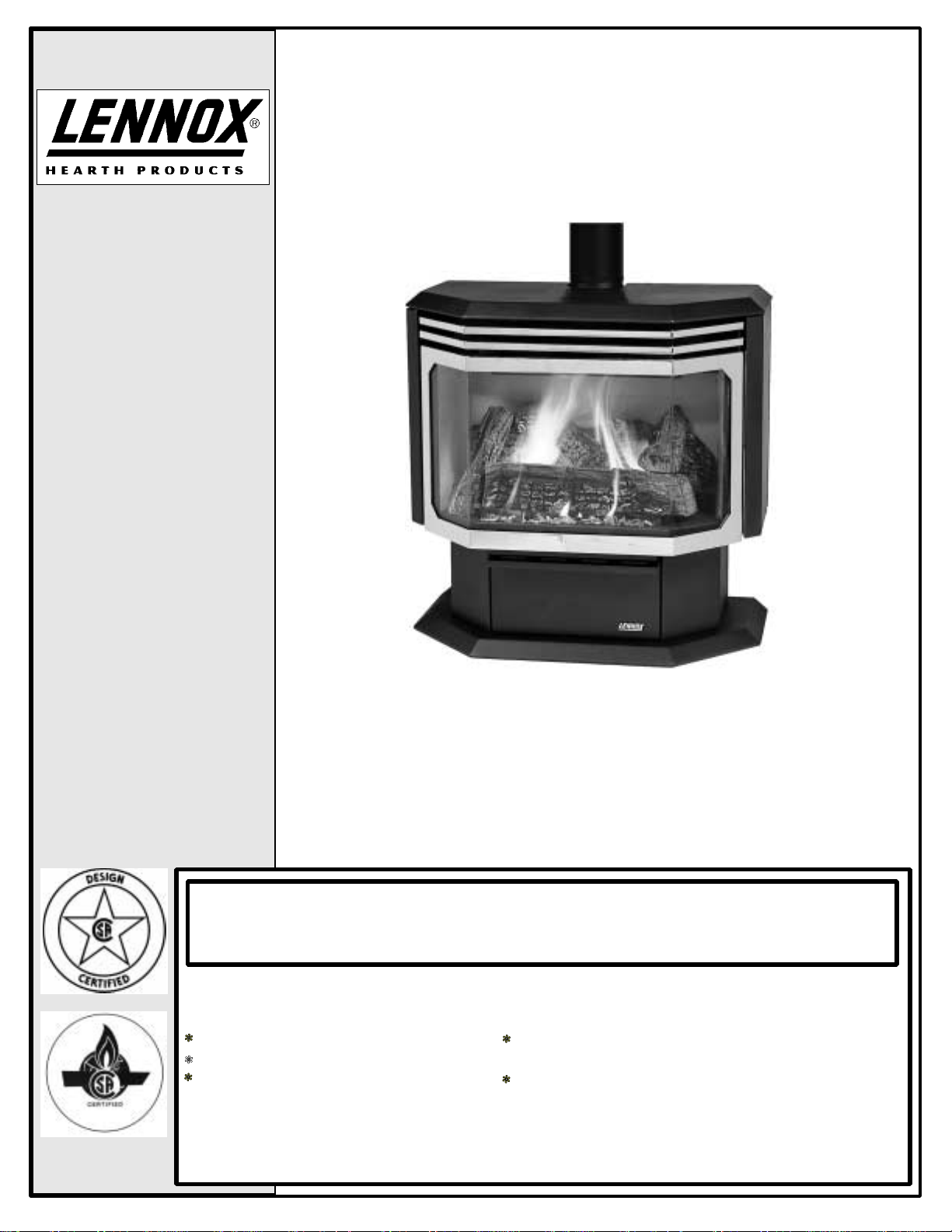
FREESTANDING
VENTED GAS
FIREPLACE
HEATER
INSTALLATION AND OPERATION
MANUAL
RETAIN THESE
INSTRUCTIONS
FOR FUTURE
REFERENCE
Shown with optional gold door and brickaded interior
MODELS L30 BF-2 (B-Vent)
P/N 775030M, IR, 06/01
WARNING
If the information in this manual is not followed exactly, a fire or explosion may result causing
property damage, person injury or loss of life.
Do not store or use gasoline or other flammable vapors and liquids in the vicinity of this or any
other appliance.
WHAT TO DO IF YOU SMELL GAS
Do not try to light any appliance.
Do not touch any electrical switch.
Do not use any phone in your building
Immediately call your gas supplier from a neighbor's phone. Follow the gas supplier's instructions.
If you cannot reach your gas supplier, call the
.
fire department.
Report No.
189122-1050009
Installation and service must be performed by a qualified installer, service agency or gas supplier.
This appliance is only for use with the type(s) of gas indicated on the rating plate. This appliance is
not convertible for use with other gases, unless a certified kit is used.
Page 2

IMPORTANT WARNINGS / CAUTIONS
CAUTION: Read this manual thoroughly before starting installation. For your safety, follow the installation, operation and maintenance instructions exactly without deviation. Failure to follow these instructions may result
in a possible fire hazard and may void the warranty. If this appliance is not properly installed, a house fire may
result. Contact local building or fire officials about restrictions and installation inspection in your area.
1. WARNING: Improper assembly, installation, adjustment, alteration, service or maintenance can
cause injury and / or property damage. Installation and service must be performed by a qualified installer, service agenc y or the gas supplier.
Except when complying with local codes, any
deviation from the installation and / or operating
instructions contained in this manual will void
the appliance warranty and may be hazardous.
2. Due to high temperatures, this appliance should
be located out of traffic and away from furniture,
draperies and not in windy or drafty areas.
3. The appliance must NOT be connected to a
chimney flue serving a separate solid-fuel burning appliance.
4. C AUTION: HOT WHILE IN OPER ATION. An appliance hot enough to warm your home can severely burn anyone touching it. Keep children,
clothing and furniture away. Contact may cause
skin burns. Do not let children touch the appliance. Train them to stay a saf e distance f rom the
unit.
5. Do not place clothing or other flammable material
on or near the gas appliance. The minimum
clearances must be mainta ined for all combustible surfaces and materials including; furniture,
carpet, drapes, clothing, wood, papers, etc.
6. Do no t connect 110-12 VAC ( residential line v oltage) to the gas control valve or control wiring
system of the unit.
7. Any safety screen or guard removed for servicing must be replaced prior to operating the appliance.
8. WARNING: Use only the glass door certified with
this appliance. Exercise caution to protect glass
from impact. Do not operate the appliance with
broken glass or use substitute materials.
9. DO NOT USE t his appliance if any part h as been
under water. Immediately call a qualified service
technician to inspect the appliance and replace
any part of the control system and gas control
which has been under water.
10. Do not burn wood or other material in this heater.
11. WARNING: The appliance area must be kept clear
and free from combustible materials, gasoline
and other flammable vapors and liquids.
12. Do no t use a blo wer in sert, h eat ex chang er ins ert
or other accessory not approved for use with this
appliance.
13. This appliance is not for use with air filters.
14. The appliance should be inspected and maintained at least annually by a professional service
person. More frequent cleaning may be required
due to excessive lint from carpeting, bedding material, etc. It is imperative that contro l compartments, burners and circulating air passageways
of the appliance be kept clean.
15. This appliance is only for use with the type of
gas indicated on the rating label (located inside
control panel). This appliance is not convertible
for use with other fuel unless a certified kit is
used.
16. C AUTION: Under no circumstances should these
appliances be vented to other rooms or buildings. These appliances must only be vented to
the outside. Vent terminations shall not be recessed into a wall or siding (V ent must terminate
vertical).
17. This appliance i s equipped with a safety co ntrol
system (spill switch) designed to protect again st
improper venting of combustion products or vent
blockage.
18. Never seal the opening at the rear of the stove.
19. Prov isions must be made to ensu re an adequate
supply of combustion and draft hood dilution air
to the room where the appliance is installed.
20. It is impe rativ e that t he flow passage s of the ven t
termination cap remain unrestricted.
21. WARNING: These appliances must be properly
connected to a venting system. Operation of
these gas appliances when not connected to a
properly installed and maintained venting system
can result in carbon monoxide (CO) poisoning
and possible death.
22. WARNING: Do not modify the venting system,
appliance, or controls in any way. Be advised,
any modification can be dangerous.
23. IM PORTANT: Do not exceed the maximum horizontal runs allowed. In stall at ion in a rea s e xp osed
to strong winds may cause sooting.
24. SAVE THESE INSTRUCTIONS.
PAGE 2
Page 3

TABLE OF CONTENTS
Important Warnings ................................................ 2
Testing / Listing, Using this Manual ........................ 3
Planning Your Installation .....................................4-6
Installation .......................................................... 7-11
Care and Operation...........................................12-13
Propane Conversion..........................................14-15
Maintenance......................................................16-17
Wiring Diagrams..................................................... 18
Troubleshooting...................................................... 19
CONGRATULATIONS ON THE PURCHASE OF
YOUR NEW GAS APPLI ANCE MANUFACTURED BY
LENNOX HEARTH PRODUCTS.
When you purchased your new gas fired heater, you
joined the ranks of thousands of concerned individuals whose answ er to their home heating need s
reflects their conce rn for aesthetics, effici ency and
our environment. We extend our continued support
to help you achieve the maximum benefit and enjoyment available from your new gas fired heater.
It is our goal at Lennox Hearth Products to provide
you, our valued customer, with an appliance that
will ensure you years of trouble free warmth and
pleasure.
Replacement Parts / Optional Accessories............ 20
Specifications .........................................................21
Safety / Listing Label.............................................. 22
Ownership Record and Service Log ......................23
TESTING / LISTING
This appliance is tested and certified as safe for residential use by an internation ally recognized testing and
certification ag ency. The safety t ests are conduc ted in
accordance with Americ an National Standards Institute
(ANSI) requirements . The L30 BF-2 appliance is test ed,
certified, and listed by the CSA, AGA, CGA to ANSI
Z21.88 - 1998 Vented G as Fireplace Heat ers and CS A
2.33 - 1998 Vented Gas Fireplace Heaters.
Approved Venting: This appliance may be vented with
any listed class B c himney components installed in accordance with manufacturer s instr ucti ons . See pag e 7.
PACKAGING LIST
This appliance is packaged with an accessory package,
which contains the following:
One - Installation and operation instructions manual.
One - Warranty.
One - Log set and embers.
One - LP conversion kit.
One - 9’ electrical power cord.
Thank you for selecting a Lennox Hearth Products
gas fired heater as the answer to your home heating
needs.
Sincerely,
All of us at Lennox Hearth Products
USING THIS MANUAL
Please read and carefully follow all of the instructions
found in this m anual. Pleas e pay special attention t o the
safety instructions provided in this manual. Following
the Homeowner’s Care and Operation Instructions included here will assure that you have many years of
dependable and enjoyable service from your appliance.
PAGE 3
Page 4
PLANNING YOUR INSTALLATION
LOCAL AND NATIONAL CODE REQUIREMENTS
The installation of these appliances must conf orm with
local codes or, in the absence of local codes, with the
National Fuel Gas Code, (for USA) NFPA 54 / ANSI
Z223.1-latest edition.
Air Circulation Blower: The blower electrical power
cord must be electrically grounded per local codes or
per electrical codes:
In USA, NEC, ANSI / NFPA 70-1987.
In Canada, CSA C22.1
WARNING
Electrical Grounding Instructions. This appliance is equipped with a three-prong
(grounding) plug for your protection against
shock hazard and should be plugged directly into a properly grounded three-prong
receptacle. Do not cut or remove the
grounding prong from this plug.
WARNING: To avoid electrical shock, always ensure
that the power cord is u nplugged (i.e., there is no electrical power to the circulation blower) before handling
the circulation blower or performing any work on the
appliance.
GAS PRESSURE (WC = Water Column)
Minimum inlet gas supply pressure for the purpose
of input adjustment:
Natural Gas - 4.5” WC min. – 7.0” WC max.
Propane (LP) - 11” WC min - 13.0” WC max.
Manifold gas supply pressure:
LOW HIGH
Natural Gas - 1.8” + / -.3” WC (to) 3.5” + / -.3” WC
25,000 BTU / hr 37,000 BTU / hr
Propane (LP) 6.6” + / -.3” WC (to) 10” + / -.3” WC
28,000 BTU / hr 35,000 BTU / hr
Note: ” WC = Inches Water Column
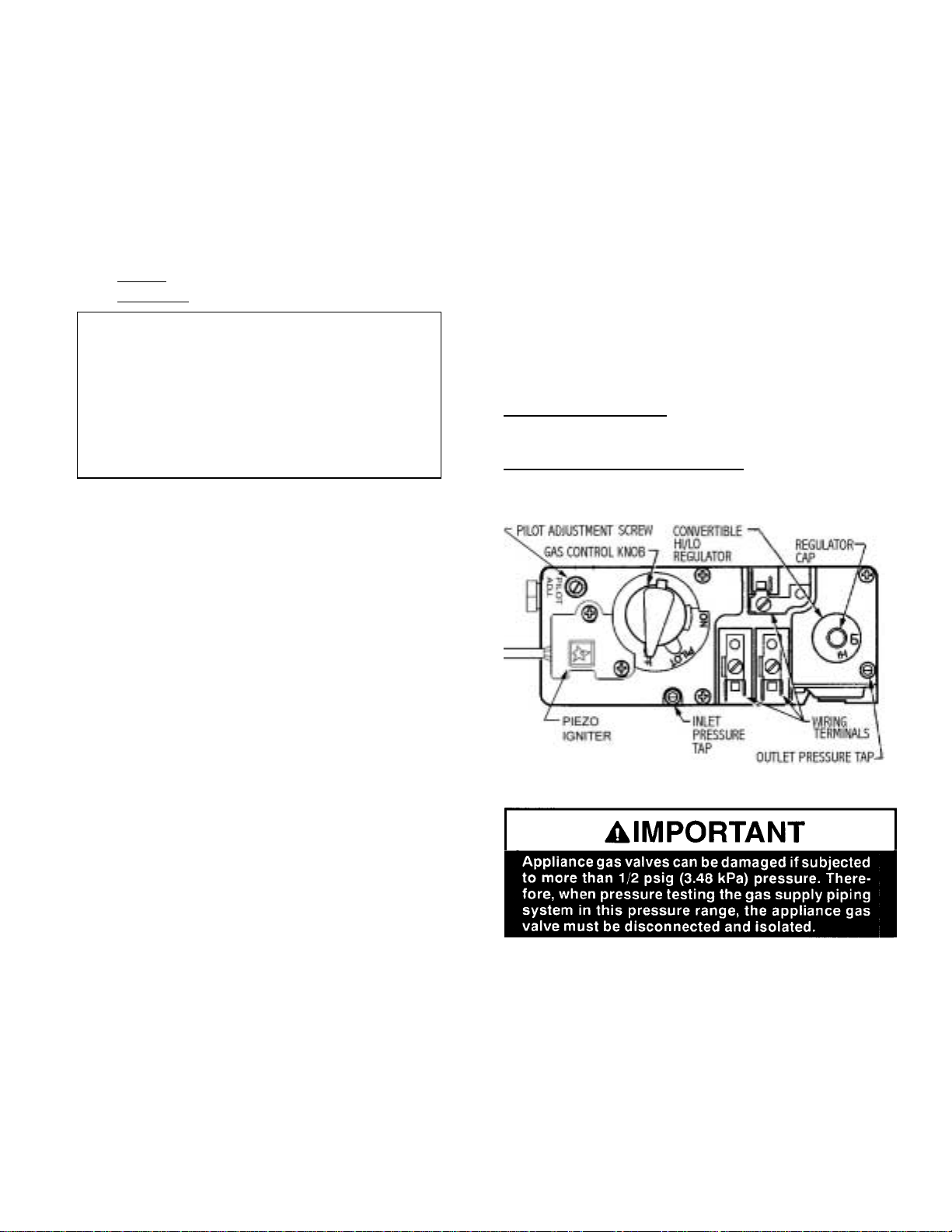
PRESSURE TAPS
Gas Inlet Pressure T ap - Located on bottom left of gas
valve.
Gas Outlet (m anifold) press ure tap - Located on b ottom
right of gas valve.
Gas Control Valve
High Altitude: Gas inputs shown are for elevat ions up
to 4500 feet. For ele vations above 4500 feet, co ntact
your gas supplier or qualified service technician regarding the necessary deration of appliance (deration:
replacing burner orifice with a smaller one to reduce
input). Ratings must be reduc ed at the rat e of 4 per cent
for each 1,000 feet abo ve sea level. Ref er to (for USA)
NFPA 54 / ANSI Z223.1-latest edition for orifice resizing.
TOOL / EQUIPMENT LIST
The following tools and equipment are recommended
for completing the partial assembly required when the
appliance is installed:
• 7/16”, 3/4” open end wrenchs.
• 1/4”, 3/8” nut drivers.
• Pipe wrench.
• Phillips head screw driver.
• Flat head screwdriver.
• Pipe sealant compound.
• Leak test fluid“U” tube manometer or pressure gauge (0 -
16” (inches water column) H2O scale.
Pressure Testing: See Pressure Testing on page 8.
PAGE 4
Page 5

PLANNING YOUR INSTALLATION
QUESTIONS TO ASK THE LOCAL BUILDING OFFICIAL
Correct installation is c r itical a nd imperative for reduc ing
fire hazards and perilous con ditions that c an ar ise when
gas appliances func tion im pr operly. T he app liance m ust
be installed per manufacturers’ instructions.
Gas appliance equipment and installations must conform to appropriate local codes and applicable state
and federal requirements. Familiarity with these requirements before installation is essential. Important
considerations to discuss with local building officials
include:
1. Applicable codes (i.e. Uniform Mechanical Code,
State or Regional Gas Codes, National Fuel Gas
Code)?
2. Local amendments?
3. Recognized testing lab: CSA / AGA.
4. Is a permit required - cost?
5. In some states or municipalities, a lice nsed gas fitter or plumber m ay be required to install this appliance. Check with your local buildi ng official for requirements in your area (i.e. Is a license required
for installation of gas supply line)?
6. Maximum amount of gas pipe without a pressure
test - type of test required?
7. Are below grade penetrations of the gas line allowed?
8. Is concealed gas piping allowed?
9. Specific requirements of concealed fittings?
10. Is rigid pipe to appliance required?
11. Allowed piping materials?
12. Shut-off valve required within 4 feet of the firebox?
13. May the shut-off valve be concealed?
14. Rooms where the installation is not allowed?
In the absence of local codes, installation should
conform to the National Fuel Gas Code, also known
at ANSI Z223.1-NFPA 54.
PAGE 5
Page 6
PLANNING YOUR INSTALLATION
CLEARANCES TO COMBUSTIBLE MATERIALS
These appliances can be installed in most residential room
configurations , parallel to a rear or adjac ent wall, or in an
alcove that allo ws for the m inim um c learanc es to com bus tible surfaces. Yo ur local buildi ng inspector s hould review
your plans prior to installation.
When installing this appliance, provide adequate clearances around air openings and adequate clearances for
purposes of servicing and proper operation.
As determ ined through t he safety cert ification of this un it,
a minimum clearance to combustible materials must be
maintained around specific areas of the gas appliance.
(See Figures 1, 2 and 3)
The clearances listed here are minimum distances and
only apply in the configuratio n shown. Do not use clearances from one installation configur ation with cleara nces
from another to obtain closer clearances.
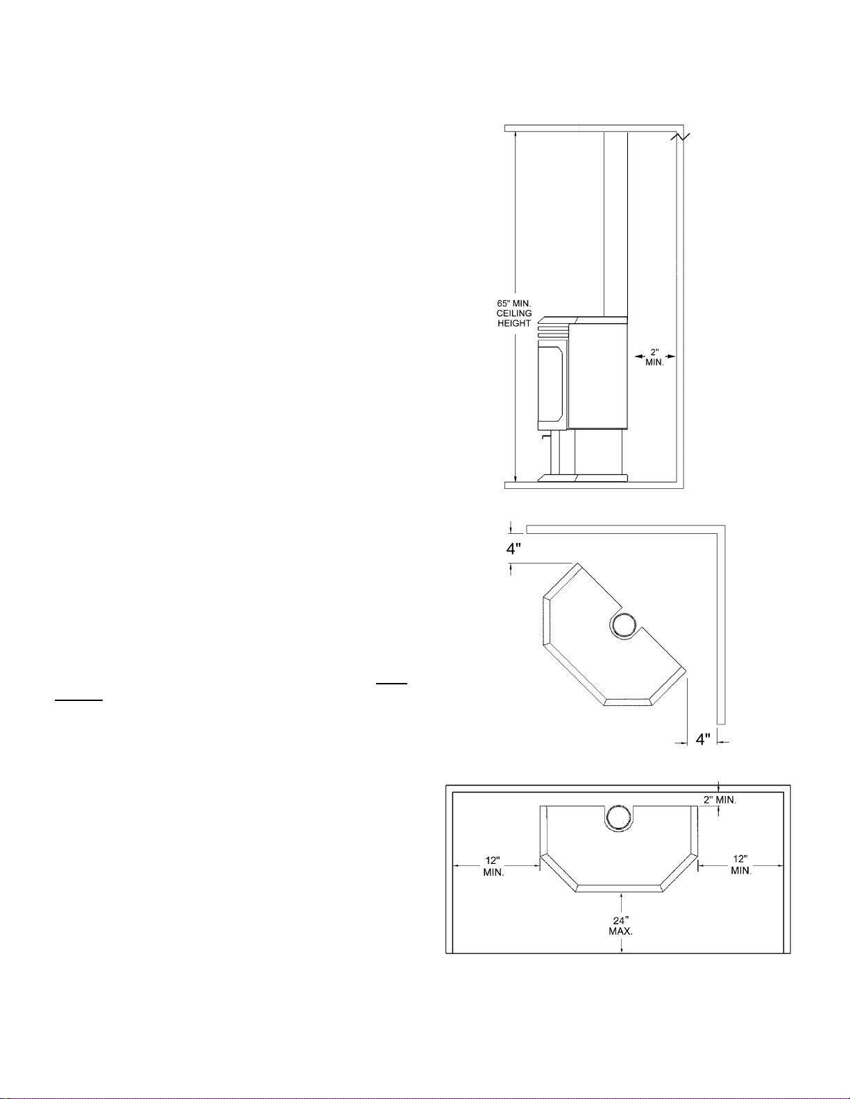
Top of appliance (min.) 36” (inches)
This includes any projections such as shel ves, w indow si lls,
mantels, etc. above the appliance.
Back Wall 2" (inches)
Side Wall 12" (inches)
Corner (45° angle) 4" (inches)
stove corners to wall
Ceiling Minimum 65" (inches) from floor
Alcove Min. Height 65" (inches) from floor
Alcove Min. Width 54" (inches)
Alcove Max. Depth 24" (inches) from unit face.
The stove can not be placed deeper into an alcove than 24” from
the stove face to alcove opening.
Floor 0 inches
Rear Wall or Alcove
Fig. 1
Corner
FLOOR PROTECTION
When installed d irectly on carpeting, • tile or other combustible material other than wood flooring, the appliance
shall be installed on a m etal or wo od pan el ex tendin g the
full width and depth of the appliance (♦ see note below).
Notes:
• Ceram ic tile is non-combus tible and does not requir e
a wood or metal panel under the appliance.
♦ Models with a pedestal base where base dim ensions
exceed width and depth of stove body, qual ify as the
floor protection
Fig. 2
Rear Wall or Alcove
Fig. 3
PAGE 6
Page 7
INSTALLATION See Pipe Manufacturers clearances for Pipe Clearances Venting Requirements
EXAMPLES OF VENTING INSTALLATION APPLICATIONS
Model: L30 BF-2 (B-Vent) Venting Requirements
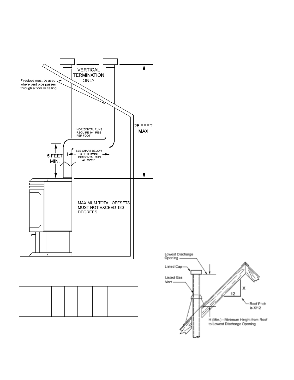
Approved for vertical termination only.
Venting Configuration Requirements:
A minimum of 5 feet vertical pipe is required to vent the
appliance. Lengthy horizontal pipe runs require sufficient
length of vertical pipe to deliver adequate draft. Use the
table above as a guide in planning your installation. The
use of multiple 45° or 90° elbows should be compensated by providing a ddi tio nal vertical pipe run .
This appliance has a 4” B-Vent flue collar and may be
installed with listed B-Vent piping and components.
Refer to the pipe manufacturer’s installation instructions
for specific requirements for their product. Maintain
proper cle arances to com bustible m aterials as spec ified
by the pipe manufacturer. W henever vent pipe is run
horizontally, maintain a minimum 1/4” ri se per foot. Exterior B-Vent exhaust systems should be enclosed in a
chase to avoid rapid cooling of exhaust gases in the
vent. Suc h cooling c ould produce c ondensati on of flue
gases or ex haust gas spi llage. The use of a chase is
highly recommended in colder climates.
VERTICAL VENT TERMINATION REQUIREMENTS
The vent termination clearances above the high side of an
angled roof is follows:
Ref. NFPA 54 / ANSI Z223.1, 7.6
Roof Pitch Feet Meters
Flat to 6/12 1.0 0.3
6/12 to 7/12 1.25 0.38
7/12 to 8/12 1.5 0.46
8/12 to 9/12 2.0 0.61
9/12 to 10/12 2.5 0.76
10/12 to 11/12 3.25 0.99
11/12 to 12/12 4.0 1.22
12/12 to 14/12 5.0 1.52
14/12 to 16/12 6.0 1.83
16/12 to 18/12 7.0 2.13
18/12 to 20/12 7.5 2.29
21/12 to 21/12 8.0 2.44
Maximum Horizontal Pipe Run s for Given Vertical Pipe
Run (in feet)
Vertical run
in feet
Maximum
horizontal
run in feet
5’ 6’ 8’ 10’ 15’ 20’
4’ 6’ 8’ 10’ 15’ 20’
Note: Maximum allowable horizontal pipe run is 20
feet.
PAGE 7
Page 8
INSTALLATION
GAS SUPPLY HOOKUP
If using pipe other than black iron pipe see NFPA 54-National
Fire Protection Association / ANSI Z223.1-American National
Standards Institute; and local code for specific requirements
for the type of pipe used. Alternative gas piping systems such
as CSST may be used subject to local code and proper sizing.
This appliance is equipped with a flexible gas line and
fitting for a gas supply line connection. Connection can
be made using either the 3/8” NPT male fitting or, by removing the fitting, t o the flex line 3/8” female f lare. The
flex line can be routed to the gas supply through either
the pedestal bottom or through the rear pedestal cover
depending upon the orientat ion of the supply line. Som e
areas may have certain restrictions against the use of
flexible gas lin es. Chec k local co des. T he gas a pplia nce
control valve has a 3 /8” NPT fem ale type inlet for the gas
supply line, if hard plumbing is requir ed.
If the gas supply will b e routed to the appl iance from the
rear, the flexible g as line f or hook up is rea dil y acc ess ible.
If the gas supply will b e routed to the appliance through
the flooring, remove th e rear panel. Redirect the flex ible
gas line through the large hole in the c enter of the pedestal base for gas supply connection.
A gas supply line must be run to the appliance by a qualified professional. The plumbing of the gas line must
comply with National Standards; NFPA 54-National Fire
Protection Associatio n / ANSI Z223.1-American N ational
Standards Institute; and loca l cod e.
Gas piping must not run in or throu gh air ducts, clothes
chutes, chimneys or gas vents, dum b waiters or elevator
shafts.
Piping should be sloped 1 / 4” per 15 feet (6mm per
4.6m) upward toward th e meter from the appliance. The
piping must be supported at proper intervals every 8 to
10 ft. (2.4m to 3.1m) using suitable hangers or straps.
The gas supply line must be purged of air before it is
connected to the appliance.
An accessible, approv ed shut-off valve m ust be installed
upstream of any conn ector so that the app liance may be
isolated to allow service, removal, and replacement
(within six feet of the applianc e per NFPA 54, or twelve
inches in some c odes). A shut-off valve is provided with
this appliance.
IMPORTANT: In case emergency shut-off is required,
shut off main manual gas valve and disconnect main
power to appliance. These devices should be properly
labeled by the installer.
PRESSURE TESTING:
• The appliance main gas valve must be disconnected from the gas
supply piping system during any pressure testing of that system at
test pressures in excess of *1/2 psi (3.5 kPa).
PAGE 8
• The appliance must be isolated from the gas supply piping
system by closing its individual manual shut-off valve during
any pressure testing of the gas supply piping system at test
pressures equal to or less than *1/2 psi (3.5 kPa).
Make the connection t o the gas supply line us ing the
correct fitting required to the shut-off valve.
Install a drip leg where condensates might accumulate. Sediment traps, lik e drips an d col lection t ees, ar e
required to be installed. Traps collect moisture and
intercept and hold foreign objects which might block
orifices and valves. A drip leg should be installed in
vertical pipe runs to the appliance.
Supply Line Size Requirements
The proper gas line diameter must be used to run
from the supply regulator (at the gas company meter )
to the appliance. Never use galvanized or plastic
pipe. Refer to the table below for suggested si zing of
the gas supply line.
Suggested Sizing of
Schedule 40 Pipe Supply Line
Schedule 40 Pipe
Length (Feet)
0-10 1/2 3/8
10-40 1/2 1/2
40-100 1/2 1/2
100-150 3/4 1/2
150-200 3/4 1/2
Schedule 40 Pipe
Inside Diameter (Inches)
Natural Gas LP. Gas
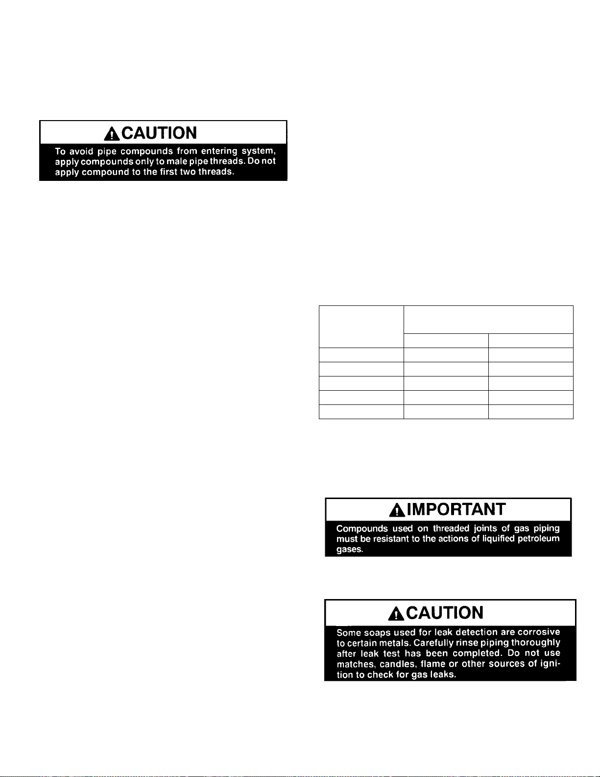
Use an approved pipe s ealant compound for NPT fittings. After all pipe connections are made, apply
normal gas line pressure: 7.0” W.C. for natural gas;
11.0” W.C. for LP gas (propa ne) and use an ap proved
leak detection solut ion to test f or the tightn ess of each
pipe connection joint.
IMPORTANT: All connections must be checked for leaks with
a leak detector or soa py wat er solu tio n. Nev er chec k f or gas
leakage with an open flame!
* Note: ½ psi = 14” WC (inches water column).
Page 9
INSTALLATION
DOOR OPERATION
After setup of the logs and em bers is com plete, the g lass
door must be closed. The glass door is mounted on
hinges at the left side of the firebox and is sec ured in the
closed position by two draw latches m ounted on th e right
side of the firebox. The latch tension is preset at the
factory. Over time, adjustm ent of the latch tension may
be necessary to maint ain a tight door seal. This adjustment can be made b y spin ni ng t he latching r od in the ro d
guide. Care should be ex ercised to not adjust the tension too high. Caution: Never operate the appliance
with the glass door open.
If glass door removal is required for replacement or
maintenance, the door can be removed Do not attempt to
remove or replace broken glass in the door assembly.
Contact your Lennox dealer for glass replacement. To
Remove Door:
1. Remove the glass door assembly from appliance
as follows:
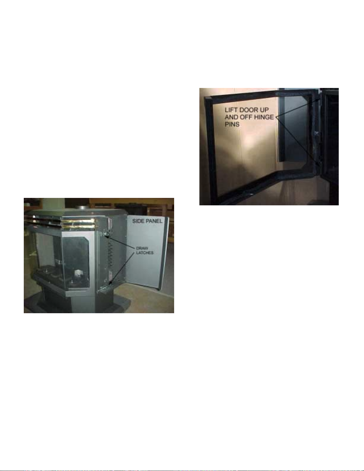
a. Open the right and left side panels (held cl osed
by magnets in the front. The panels hinge to
back).
b. Open the two draw latches mounted on the r ight
side of the door by pulling them forward. Swing
open door. See picture in lef t column of this page
showing their location.
c. With the door open, lift the door straight up and
off the hinge pins. Set door aside.
PAGE 9
Page 10
INSTALLATION
GAS APPLIANCE FINAL ASSEMBLY
After the appliance has been properly installed and all
gas connections ha ve been made and tested, you can
now install the log set. See Door Assemb ly on page 11
for door removal instructions.
INSTALLING LOG SET:
WARNING: If logs are not installed according to the
directions in this manual, flame impingement and
improper combustion could occur and result in excessive production of carbon monoxide (CO), a colorless, odorless, toxic gas.
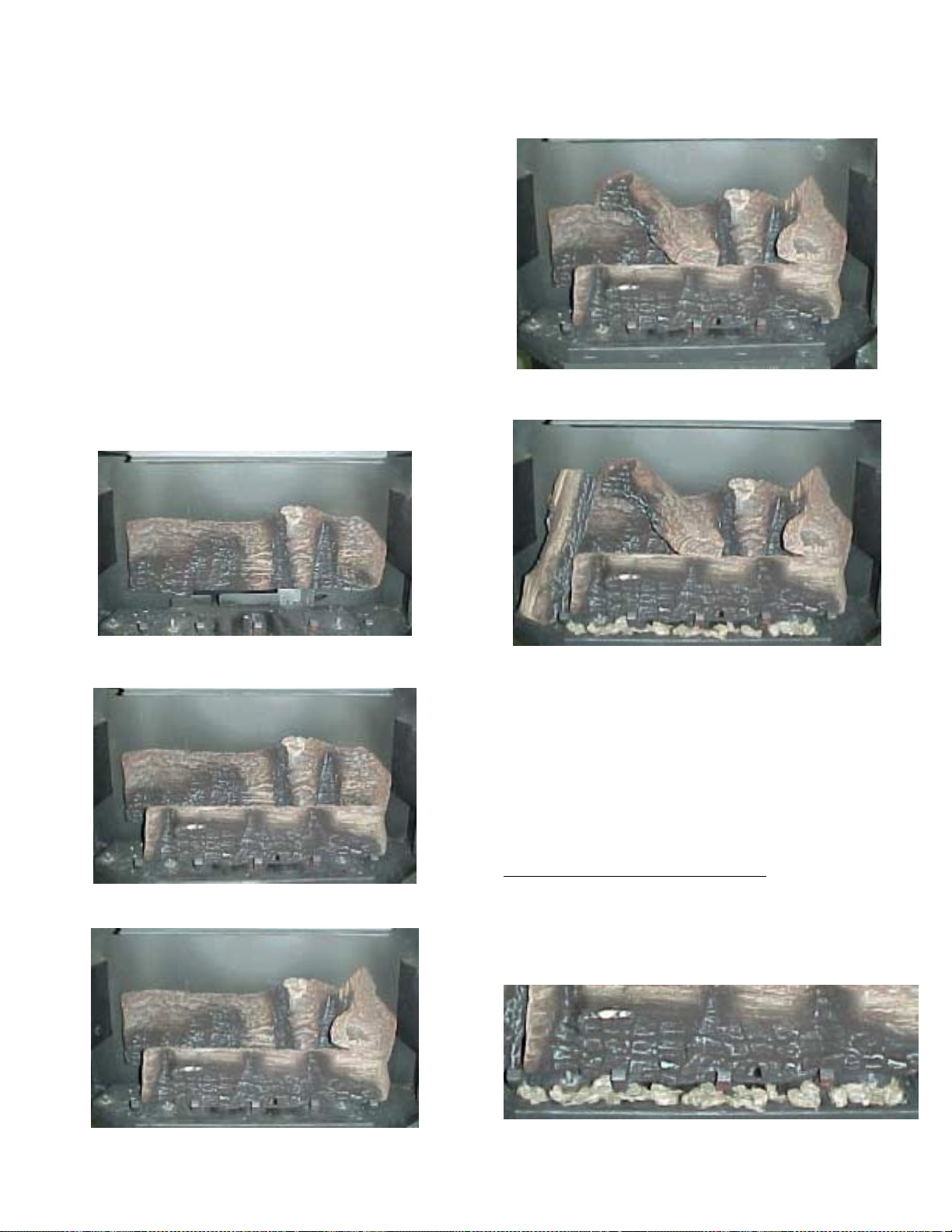
This appliance is equipped with a five-piece log set.
Carefully install the logs into the firebox as shown on
this page. All logs shou ld fit d own onto p ins and mounts
provided. This will ensure a proper flame and safe
combustion.
1. Carefully place the larg est log in the rear of the firebox as shown in the following illustration.
4. Install the center top twig as shown in the f ollowing
illustration.
5. Install the left top twig and em bers as shown in the
following illustra t io n.
2. Ins tall the front l og as shown in the followin g illustration.
3. Install the right top twig as shown in the following
illustration.
Glowing Embers
One package of em ber material has b een includ ed with
this gas appliance. You will not need to use the entire
bag (additional em ber material is provided f or your future maintenance needs).
IMPORTANT: The quantity and placement of the
ember material can affect stove performance the refore it is very important that it be placed as shown
in the picture on instruction # 5 and shown below.
Proper Placement of Ember Material: Unpackage and
divide the fine ember material (mineral wool) into
thumbnail sized fluf f y pieces. Dis tribut e th e p ieces over
the top of the front burner ports and filling the area in
front of and beneath the for ward log and r unnin g the f ull
length of the log.
PAGE 10
Page 11
INSTALLATION
INSTALLATION CHECK LIST
Read and understand these instructions before using
appliance. Go through this installation checklist:
G Ensure that the log set is prop erl y instal led. Us e cau-
tion when handling the logs. See page 10.
G Reinstall the door f rame as sembly. See Do or Opera-
tion on page 9.
WARNING: Do not operate appliance with the
glass front removed, cracked or broken. Replacement of the glass should be done by a
qualified technician.
G Ensure venting termination cap is unobstructed.
G Check to see that wiring is correct and is enclosed
inside the stove pedestal base (See page 18).
G Verify that the gas line has been purged of air.
G Test all connections for leak s (factory and field) with
a leak detector or soap y water solution. If you sm ell
gas, do not attempt to light this appliance. Follow
safety instructions on the front cover of this manual.
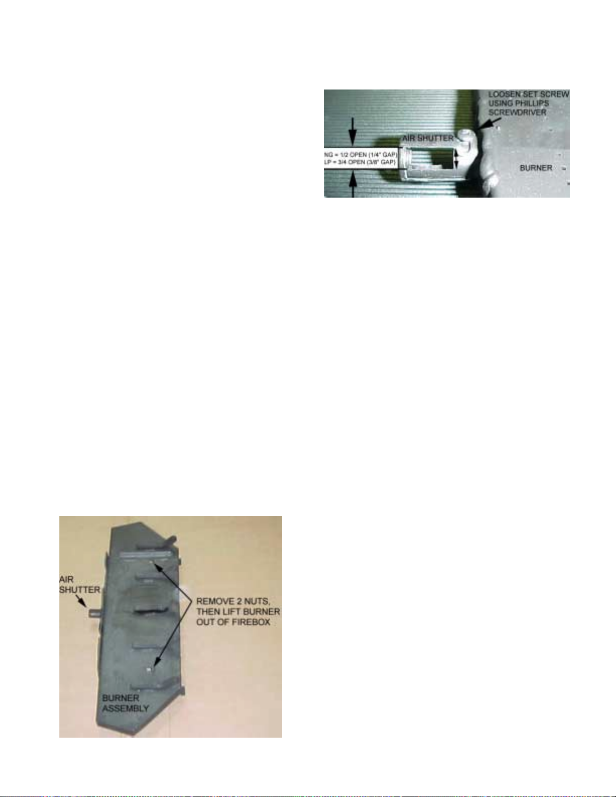
2. Adjust gap as shown in following picture.
3. Reinstall burner. Do not overtighten nuts
(finger tight only).
G Light the applianc e f oll o wing t he instructions o n pa ge
13 (Care and Opera tion). Relight the m ain burner in
both the HI, and LO positions, and verify proper
burner ignition and operation.
NOTE: Upon the initi al firing of your ne w gas stove,
you will notice a stro ng odor. This will la st up to two
hours. It is recommended to open the windows to
allow fresh air to circulate into the room.
G Burner Air Shutter opening to be:
Natural Gas – 1/2 open, Propane 3/4 open.
Some adjustment f rom standard may be necessary
for the desired flame characteristics (see Burner
Flame Appearance, page 17). To adjust air shutter:
1. Remove burner from firebox by removing the 2
nuts as shown in the following picture. Then lift
burner up and out of firebox.
WARNING: If the pilot does not light after 1 minute, wait at least 5 minutes for gas to clear before
attempting again.
G With burner lit, check to mak e sure that the inlet gas
and manifold pressures are correct (see Gas Pres-
sure, page 4). Verify that the p ilot and main burner
ignition and operation are correct .
PAGE 11
Page 12

CARE AND OPERATION
FOR YOUR SAFETY READ BEFORE LIGHTING
WARNING: If you do not follow these instructions exactly, a fire or explosion may result
causing property damage, personal injury or
loss of life.
A. This appliance has a pilot which must be lit.
When lighting the pilot, f ollow these instructions
exactly.
B. BEFORE LIGHTING smell all around the appli-
ance area for gas. Be sure to smell next to the
floor because some gas is heavier than air and will
settle on the floor.
WHAT TO DO IF YOU SMELL GAS:
• Do not try to light any appliance.
• Do not touch any electric switch; do not use
any phone in your building.
• Immediately call your gas supplier from a
neighbor’s phone. F ollow the gas s upplier ’s instructions.
• If you cannot reach your gas supplier, call the
fire department.
C. Use only your hand to push in or turn th e g a s
control knob. Never u se t ool s. If the knob w ill no t
push in or tu rn by ha nd, d on’ t try to re pai r it , call a
qualified service te chnicia n. Force or atte mpted
repair may result in a fi re or explosion .
D. Do not use this appliance if any part ha s been un-
der water. Immediately call a qualified service
technician to inspect the appliance and to replace
any part of the control system and any gas control
which has been un de r wa te r.
Gas Control Valve
LIGHTING AND SHUTDOWN INSTRUCTIONS
1. STOP! Read the s afet y inform ation o n this pag e or on labe l
(on appliance).
2. Tur n off all electric al power to the appliance (un plug blower
power cord). Make sure the burner ON/OFF switch is in the
OFF position.
3. To gain access t o the g as contr ols , s win g th e co ntro l acc ess
door open. The contr ol access door is located directly under
the window.
4. Push in gas control knob slightly and turn clockwise
“OFF.”
NOTE: Knob cannot be turned from “PILOT” t o “OFF” unless knob is pushed in slight ly. Do not force.
5.Wait five (5) minutes to clear out any gas. Then smell for
gas, including near the floor. If you smell gas, STOP! Follow “B” in the safety information above on this label. If you
don’t smell gas, go to the next step.
6.Visually locate the pilot located in the center of the firebox
beneath the rear ceramic log.
7.Turn knob on gas control counterclockwise
8.This appliance contains a spark ignition system (piezo igniter), which is used to light the pilot. Push in the gas control
knob all the way and hold it in. Immediately press the button
on the piezo igniter located to the left of the gas control knob.
The spark produced by the piezo igniter should light the pilot.
Continue to hold the control knob in for about one (1) minute
after the pilot is lit. Release the gas control knob and it will
pop back up. Pilot should remain lit.
• If it goes out, repeat steps 4 through 8.
• If the knob does not pop up when released, stop and im -
mediately call your service technician or gas supplier.
• If the pilot will not stay lit af ter 3 or 4 tries , turn t he gas con-
trol knob to “ OFF” a nd ca ll your serv ice tec hnician or gas
supplier.
9. Turn gas control counterclockwise
switch, located either on the control panel or the exterior
side panel, to operate main burner. Adjust variable pressure dial (RB Regulator / Flame Height Control) to set
burner flame to desired heat output.
10. Swing the control access door closed.
11. Turn on electrical power to the appliance (plug in blower
power cord. See pa ge 13 , Circulation Blower Operation.)
3333 to “ON.” Use rocker
3333 to “PILOT.”
2222 to
Pilot Assembly
TO TURN OFF GAS TO THE APPLIANCE
1. Turn off al l el ectr ic power to t he a ppliance if s er vice is t o be
performed.
2. To gain access to the gas controls, swing the control access door open. The c ontro l access d oor is located directl y
under the window.
3. Pus h in gas control k nob slightly an d turn clockwis e
“OFF.”
NOTE: Knob cannot be turned from “PILOT” to “OFF” unless knob is pushe d in slig ht ly . Do no t fo rc e .
4. Swing the control access door closed.
PAGE 12
2222 to
Page 13

CARE AND OPERATION
“BREAK-IN” PERIOD
The finish on this appliance is a hig h temperature paint
that requires tim e and temperature to completel y cure.
The curing process will take 2 or 3 bur ns (heat up and
cool down periods). We recommend that you ventilate
the house during the initial bur ns. The paint emits nontoxic odors during this process.
KEEP YOUR HOUSE WELL VENTILATED DURING
THE CURING PROCESS TO PREV ENT ACTIVATION
OF YOUR HOME SMOKE DETECTOR.
Do not turn on a blower during the break -in period. Do
not place anything on the s tove sur fac e until t he pa int is
completely cured. Do not attempt to repaint the stove
until the paint is completely cured. If the surface later
becomes stained or marred, it may be lightly sanded
and touched up with spray paint (S ee Small Area Paint
Touch-Up, page 16). Paint is available at your local
authorized Lennox Hearth Products dealer. Never attempt to paint a hot stove.
CIRCULATION BLOWER OPERATION
The speed of the cir culation blower is controlled us ing
the speed control rheostat ( see following i llustration) on
the left hand side of the control p anel. The b lower s ystem is designed with a variable spee d control allowing
an infinite range of blower settings to meet the customer’s needs. W ith the rotar y switch turned f ully CCW
3, the blower is off . Tur ning the s witch CW 2 will activate the blower at its max imum speed. Further rotation
of the switch in the CW direction will r educe the speed
of the blower. At ap proxim ately 270° of CW 2 rotation,
the switch provides a minimum setting for blower
speed.
Thermostatic feature: With the control switch in any
“ON” position, the circulation blower is designed to
automatically begin op eration approxim ately 12 m inutes
after lighting the m ain burner. The blower will turn off
approximately 15 m inutes after th e main burn er is shutoff.
PAGE 13
Page 14

PROPANE CONVERSION
PROPANE CONVERSION PROCEDURE
(Only required if Propane gas is used)
This appliance is d esign ed to o perat e on na tural gas , or
propane (LP). It is f actory set for use with natural gas
and requires field conversion for use with pro pane. The
use of other fuels or c ombination of fuels will d egrade
the performance of this system and may be dangerous.
The conversion k it provid ed with this appl iance co ntains
components requir ed to c onvert t his app lianc e f rom use
with natural gas to use with pr op ane ( LP) G as. All of the
components in the propane conversion kit must be installed in order for the appliance to operate safely on
propane.
Installation Tools / Supplies
7/16” Open end wrench
Small standard screwdriver
Pipe sealant compound (must be rated for use with
LPG gas)
Parts List
• Propane RB Regulator conversion screw (Red indicates
LP gas)
• Burner Orifice (If you are at an elevation above 4500 feet
do not use the orifice provided in this kit. Contact your
gas supplier to obtain a smaller orifice)
• Pilot Orifice
• Label, Converted to (LP) Propane – Affix to valve
• Label, Converted to (LP) Propane – Affix to stove body
Avertissement: cet équipement de conversion sera installé par une agence qualifiée de service conformément aux instructions du fabricant et toutes exigences et codes applicables de l’autorisés avoir la juridiction. Si l’information dans cette instruction n’est
pas suivie exactem ent, un feu, explosion ou pr oduction
de protoxyde de carbone peut résulter le dommages
causer de propriété, perte ou blessure personnelle de
vie. L’agence qualifiée de service est esponsable de
l’installation propre de cet équipment. L’installation
n’est pas propre et compléte jusqu’à l’opération de
l’appareil convert i est c héque s ui vant les critèr es ét ablis
dans les instruct ions de pr opriéta ire provis ionnées a vec
l’équipement.
IN CANADA:
The conversion shall be carried out in accordance with
the requirements of the provincial authorities having
jurisdiction and in accord ance with the requirements of
the CAN1-B149.1 and .2 Installation code.
La conversion devra être effectuée conf ormément aux
recommandations des autorités provinciales ayant juridiction et conformément aux exigences du code
d’installation CAN1-B149.1 ET.2.
PROPANE Conversion Procedure
1. Turn off Gas - Turn gas control knob to the off position, and shut off the gas supply to the valve. If necessary, disconnect appliance from gas supply.
2. Caution: The gas supply shall be shut off prior to
disconnecting the electrical power, before proceeding with the conversion. Unplug blower power cord.
3. If the installation is at an elev ation below 4500 feet,
proceed to step 4.
feet, do not use the orifice provided in this kit. Contact your
gas supplier to obtain a smaller orifice).
If you are at an elevation above 4500
4. Burner Orifice Installation Procedure:
a. Remove glass door.
b. Remove logs, burner cover, and burner.
c. Use a 7/16” open-end wrench to remove gas
burner orifice.
d. Replace the burner orifice with the appropriate
burner orifice (see instruction #3).
e. Use pipe sealing compound rated f or LP gas . BE
VERY CAREFUL T HAT THE PIPE COMPOUND
DOES NOT GET INSIDE OF THE ORIFICE
(THIS COULD RESULT IN PLUGGING OF THE
ORIFICE). Using a 7/16” open-end wrench to
tighten orifice - DO NO T OVER TIGH TEN (finger
tight, then 1/2 turn maximum). *Make sure the
orifice is insert ed fully into the prim ary air shutter
fixed opening.
5. Adjust primary air shutter. Burner Air Shutter open-
ing to be: Natural Gas – 1/2 open, Propane 3/4
open. Some adjustm ent from standard may be necessary for the desired flame characteristics (see
Burner Flame Appearance, page 15).
6. Replace Pilot Orifice - Using a 7/16” open-end
wrench, remove the pilot burner hood. Replace the
pilot orifice with the one supplied in the propane
conversion kit. Then, reinstall the pilot burn er hood.
Ensure that the mark on the pilot hood is lined up
with the mark on the pilot mounting plate.
PAGE 14
Page 15

PROPANE CONVERSION
7. High / Low Pressure Regulator Installation Procedure:
a. Remove regulator cap and c onversion screw (see
following illustra t io n) .
b. Install the new conversion scr ew (Red = Propane
LP gas, Blue = Natur al Gas). Ensure that the conversion screw is f inger tight. Install the new regulator cap.
c.Affix conversion label on gas control valve body
where it can easily be seen.
10. Purge air from the gas line (see #9 above), then
connect propane gas line to the appliance. Connect
the fuel line to the insert inlet (1/2” NPT fitting) using
the fitting required.
11. Perform leak Test.
CAUTION
After this procedure is com plete with app l iance installed and connected to gas line, recheck the pilot
connection and manifold fittings for leaks, using
soapy water or a gas leak detector.
12. Lig hti ng Pr ocedure-See page 12.
Note: If the gas control knob is turned to the “off” position after pilot has been lit, the appliance must be allowed to cool for at least five minutes before pilot flame
can be relit.
13. Apply the propane conversion label to the rating
label.
The Appliance is ready for use with propane fuel as its
only fuel.
REFERENCE INFORMATION
See pages 4, 21 and 22 of this manual for the following
reference information:
Manifold Gas Pressure
Inlet Gas Pressure
Input Ratings
8. Reinstall burner cover, logs, ember wool / ceramic
rocks and glass front.
9. Purging Air from Supply Line:
This should only be done by a qualified and licensed (where applic able) profes sional. Ch eck with
your local building of ficial for qualific ations required
to perform this procedure.
BURNER FLAME APPEARANCE
A periodic visual check of burner flames should be
performed. The burner flame should appear as indicated on page 17 - Burner Flame Appearance.
PAGE 15
Page 16

MAINTENANCE
Always Turn Off Gas Control Valve Before Cleaning. Annual Maintenance Should Only Be
Performed By A Qualified Service Technician:
LOG SET
Removing & Cleaning Logs - Carefully remove the logs
(removing top logs, then lifting front log out, then rear
log). Use care when handling the fiber logs, as they become quite fragile af ter curing. Use a sm all soft-bristled
brush (e.g., a nylon paint brush) to rem ove soot, dust or
debris that may hav e accumulated on the burner or log
set. Remove the logs and burner, and clean them outside the home in a location with plenty of f resh air ventilation. Avoid breat hing fine partic ulates of dust t hat may
be generated. See page 10, Installing Log Set for instructions on reinstalling logs.
Replacing Logs - If logs become dam aged by accident
or improper handling and need replacement, use only the
proper replacement logs from manufacturer, which can
be purchased from your local dealer. See page 20.
CLEANING BURNER
With the logs removed, vacuum out any foreign matter
(lint, carbon etc.) o n the burner . Be sure t he burner ports
are “open.”
CLEANING VALVE / AIR VENTURI
Clean all lint and dust build- up around the control valve
and air shutter on th e venturi. Inspect and clean with a
brush or wire the inl et of the venturi for an y spider webs
or lint accumulation.
CLEAN EXTERNAL SURFACES
External surfaces should be kept clean and dust removed form air inlets to the appli ance. The f low of com bustion and ventilation air must not be obs tructed. The
appliance must be kept clear and free from combustible
materials, gasoline and other flamm able vapors and liquids.
SMALL AREA PAINT TOUCH-UP
The stove body is painted with a quality high-temperature
stove paint. Use onl y model TSPK-C Stove Paint, C atalog # 19L92. Do not touch-up this appliance with any
other paint.
Using one small piece of 320 grit sand paper and lightly
sand the blemish so that the edges are “feathered” or
smooth to the touch b etween the painted and bare surfaces. Do not let the sa nd paper gum up with paint, as
this will cause scratches on the metal surface. If there
are any scratches, use 600 grit sand paper ins tead. Mask
off surfaces you do not want painted. Paint lightly over
the bare surface first as this will act as an undercoat.
Then paint over a larger area i n smooth even strokes to
blend.
See Break-In Period on page 13 for information on c ur ing
the paint.
INSPECT WIRING / CAUTIONS:
1) Label all wires prior t o disconnection when servicing
controls. Wiring errors can cause improper and dangerous operation.
2) Verif y proper oper a tio n after servic in g.
3) Inspect and clean all wire connections. Ensure that
there is no melting or damage from rodents. Inspection should include:
• Terminals at the valve
• On / Off switch
• Wall Thermostat / Remote Control (optional kits)
VENTING SYSTEM
A periodic examination of the venting system must be
performed to ensure tha t the f lo w of c om bus tion a ir is not
obstructed. We recommend that you have your gas appliance checked yearly by your independent Lennox
dealer.
CLEANING GLASS
The window on the gas appliance is made from a clear
ceramic material and may be cleaned when cool with any
non-abrasive product designed for use on glass windows. Do not use abrasive cleaners on glass. The
viewing glass should be cleaned periodically. Exterior
glass may be cleaned with a glass cleaner as desired.
Interior glass - use s oap and water, or com mercial glas s
cleaner recommended for stove glass.
Note: Each time the appliance is lit, it may cause condensation and fog on the glass. This condensation and
fog will disappear in a few minutes.
CLEANING BLOWER INTAKE
The blower air intake requires cleaning at least once a
year to remove lint, dust, etc. If there are pets in the
dwelling, the intake should be cleaned at least twice a
year.
PAGE 16
Page 17

MAINTENANCE
Always Turn Off Gas Control Valve Before Cleaning. Annual Maintenance Should Only Be
Performed By A Qualified Service Technician:
PERIODIC CHECK OF PILOT AND BURNER
FLAMES
Check the operation of the pilot and cycle the burner.
Visually check the flame of the burner m aking sure the
flames are steady; not lifting or floatin g. The flam e color
should be blue at the burner with yellow body and tops.
Cycle unit a minimum of 2 times
• Watch for smooth burner ignition and shut down.
• Burner: Check flame patterns. Ensure that burner
flame appearance does not vary greatly from diagram shown on this page.
• Pilot: Ensure pilot flame appearance does not vary
greatly from diagram shown below.
PILOT FLAME APPEARANCE
A proper pilot flame should consist of torch-like flame
issuing from the pi lot hood as shown in illust ration below.
Proper Pilot Appearance
BURNER FLAME APPEARANCE
A periodic visual check of the pilot and burner flames
should be perform ed. If either the pilot or burner flam e
do not show proper appearance or behavior, as outlined
here, consult a qualified gas appliance technician.
A proper burner flame is shown above. The burner
flame should have the following characteristics after
initial start-up (le t appliance burn 15 to 2 0 minutes pr ior
to accessing flame appearance):
• Excessive impingement (contact of flame with
logs) should not occur.
• Rear burner f lames should have yello wis h tips ; no
soot should form at burner flame tips.
• Flam es should not raise off of burner (no “lifting”
of flame).
Air Shu tte r Adju stm e nt
The flame can be adjusted to give t he proper flam e appearance and to pre vent sooting on the window or logs
by adjusting the position of the primary air shutter (located at the rear center inlet to the burner). The air
shutter should be posi tioned ap prox im ately 1/2 op en f or
Natural Gas and approx imately 3/4 open for LP Gas. .
See page 10, Burner Air Shutter.
NOTE: During periods of high nat ural gas dem and, the
gas supplier m ay add “make-up gases” to the pipeline.
This addition will change the c omposition of the supp ly
gas, and may cause a change in bur ner flame appear ance. You may also notic e soot formation on the logs
and viewing windows. Chec k with your gas supplier if
you suspect a change in the composition of your gas
supply.
PAGE 17
Page 18

WIRING DIAGRAMS
GAS CONTROL AND SAFETY SYSTEM WIRING DIAGRAM
CAUTION: Label all wiring prior to disconnection when servicing c ontrols. W iring errors can caus e improper and dangerous operation. Verify proper operation after servicing.
The gas control wiring diagram shown her e should be used by ser vice technicians for guidanc e when troubleshooting
problems with the pilot safety (millivolt) system or burner remote control system or when locating system components for
repair / replacement. Note: If replacement of any of the original wire is necessary, use 105°C thermoplastic wiring.
GAS CONTROL WIRING DIAGRAM
CIRCULATING BLOWER WIRING DIAGRAM
PAGE 18
Page 19

TROUBLESHOOTING Qualified Technicians Only
PROBLEM CAUSE(S) SOLUTIONS
1) Pilot will not light, and Piezo Igniter does
not produce a heavy blue spark.
2) Pilot will not light, but Piezo Igniter produces a heavy blue spark.
3) Pilot will not stay lit. a. Thermocouple is not firmly connected to
4) Pilot flame stays lit, but main burner will
not light.
5) Main burner stays lit for up to 10 minutes
and then shuts off, pilot flame remains lit.
6) Smell of gas a. Loose fittings may be allowing gas to leak
7) A thin coating of black soot forms on the
window. NOTE: See page 16, Cleaning
Glass.
8) A white coating forms on windows, logs,
and / or inside walls of firebox.
9) Circulation blower makes a humming
sound, but there is no circulation air.
REFERENCE INFORMATION FOR QUALIFIED TECHNICIAN:
Thermopile / Thermocouple Operation
♦ Thermopile: Millivolt production should be a minimum of
325 MV with pilot only.
♦ Thermocouple: Millivolt production should be a minimum of
14 MV with pilot only.
a. Electrode wire (at Piezo Igniter) not
pushed completely on.
b. Piezo igniter is defective
a. Incorrect lighting procedure.
b. No gas to appliance due to shut valves or
disconnected gas lines.
control valve.
b. Pilot flame is not directed to top of ther-
mocouple.
c. Thermocouple is defective. Make sure
connection is solid.
a. Burner control switch (on control panel) is
in "OFF" position; or thermostat (if in-
stalled) is turned off or temperature set-
ting is too low.
b. Electrical wiring is damaged or poorly
connected
c. One of the following components may be
defective: burner control switch, thermo-
stat, vent spill switch, or thermopile.
a. Vent is blocked; flue gas is "spilling",
which activates the spill switch and shuts
down the appliance.
b. The house is negatively pressurized re-
sulting in spill switch activation.
out.
a. Burner primary air inlet is restricted or
blocked.
b. Flames make contact with logs or other
surfaces.
c. Improper venting.
a. Residues / impurities being burned off. • Follow cleaning guidelines outlined in the
a. Impeller blades in circulation blower are
dirty.
b. Circulation blower is defective.
Drop out rate
♦ TP 50-60 MV
♦ TP 1 1/2-2 Min. (3 max.) if longer, replace thermopile.
• Make sure connections are solid.
• Replace piezo igniter.
• Carefully follow the lighting / operating
instructions found in the appliance of this
owner's manual.
• Check for multiple gas shut-offs; check
gas supply lines.
• Ensure thermocouple is fully inserted into
pilot assembly.
• Replace thermocouple.
• Position the burner control switch to
"ON"; or adjust the thermostat. Refer to
manufacturer's instructions for thermostat.
• Refer to Control and Safety W iring Diagram (page 18) and check electrical
connections.
• Refer to Control and Safety Systems
Wiring Diagram (page 18). Electrically
bypass components one at a time and
replace defective item.
• Examine venting system for blockage.
Remove any blockage.
• Open a window to see if the problem is
corrected.
• Check all joints for leakage: pilot assembly, gas supply system, main burner assembly, pilot and burner adjustment
screws. Use a proper leak check solution. WARNING: Never use an open
flame to check for leaks.
• Be sure all openings (fresh air inlets) in
stove are free from dust and debris. Recheck these areas periodically.
• Make sure ceramic logs are in their correct positions.
• Check for flue blockage, disconnected
flue, improper installation. Make appropriate corrections.
MAINTENANCE section of this manual.
• Disconnect electrical po wer to circulation
blower, access blower and clean impeller
blades as outlined in the MAINTENANCE section of this manual.
• Replace blower.
PAGE 19
Page 20

REPLACEMENT PARTS Model L30-2 BF
Item # Description Catalog #
1 Trim, Decorative 52L04
2 Window Frame, Charcoal 17M63
3 Burner Assembl y 17M61
4 Blower, Air Circula tin g 52L19
5 Power Cord (blower) 52L17
6 Rheostat w / Knob
(speed control for blower)
7 On / Off Switch, Burner 52L13
8 Spill Switch 52L18
52L03
Item # Description Catalog #
9 Thermal Fan Switch 52L12
10 Control Valve NG (with LP
Conv. Kit)
11 ( 0-4500’ ) Orifice, #31, NG 52L27
11 ( 0-4500’ ) Orifice, #50, LPG 52L08
11 (4500’ ) Orifice, #32, NG 52L06
11 (4500’ ) Orifice, #51, LPG 52L09
12 Pilot Assembly NG 52L15
13 Log Set 17M59
64L98
PAGE 20
Page 21

OPTIONAL ACCESSORIES
Item # Description Catalog # Model
1 Door Kit, L30 BF-2, Gold 14M09 DK3B-G
2 Brickaded Interior Kit, L30 14M06 BRK-L30
3 Deluxe Remote Control (Thermostatically controlled) 98K99 RC-STAT
4 Remote Control (Standard On / Off) 26N04 RC
5 Wall Thermostat Kit 89L36 WTK
6 Touch-up Spray Paint Kit, Char c oal 19L92 T SPK- C
(3) Deluxe Remote Features
PAGE 21
Page 22
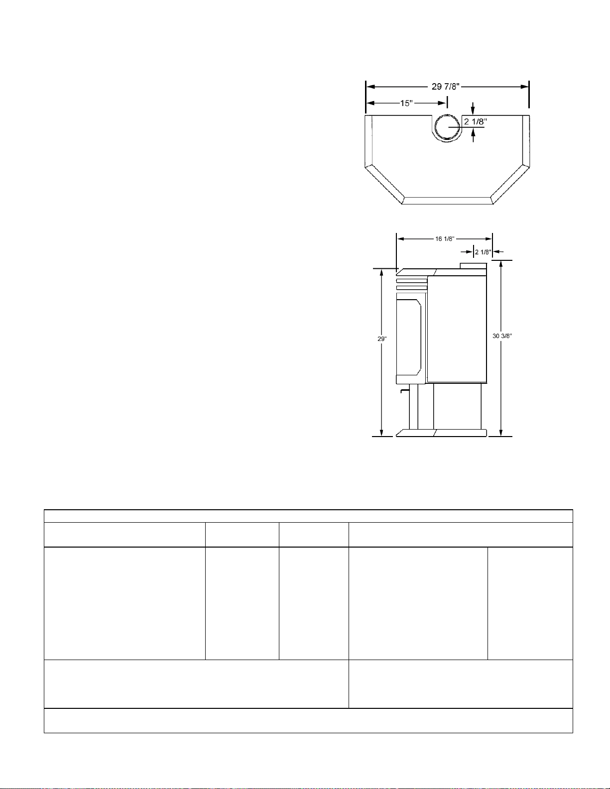
SPECIFICATIONS: Model L30 BF-2
Approx. Sq. Ft.
Heating Capacity ∼∼∼∼1500 sq. ft.
Flue Size 4” - Top Vent
Height Overall 29”
Height to Flue
Outlet 30 3/8”
Width 29 7/8”
Depth 16 1/8”
Fuel Natural Gas (standard)
(or) LP Gas (convertible).
Gas inlet 3/8” NPT-Male / Flex Line
(or) remove flex, 3/8” NPT–Female Flare.
Performance Variable Flame Control.
Features High Efficiency Heat Exchanger.
Natural Convection & Radiant Heat.
Standing Pilot / Operates During Power
Outages. Remote Control & Wall
Thermostat Capable.
Technical Honeywell Combination Gas Control
Features Valve, Millivolt - VS8520E. Safety Shut
Down Sensor (Spill Switch).
Pan Burner with Tuned Ports.
Radiant & Fan Assisted Convection
Heat.
Top View
Side View
Safety Test Tested and certi fied by CSA to A NSI
standards. Z21.88 – (1998) •••• CSA 2.33 (1998). Vented Gas Fireplace Heater .
Heat Input 25,000 to 37,000 BTU’s (Nat. Gas)
28,000 to 35,000 BTU’s (Propane)
~ Square feet heating capacities are approximations only.
Ship Weight 200 lb.’s
Dimensions shown are approximations only (+ / - ¼”)
SPECIFICATIONS
GAS TYPE NATURAL
GAS
Orifice Size #31 -.120 #50-.070” Back Wall Min. 2 In. / 51 mm
Minimum Supply Pressure 4.5” WC 10.5” WC Side Wall Min. 12 In. / 305 mm
Maximum Supply Pressure 10.5” WC 13.0” WC Corner (45°°°° angle)s
HIGH SETTING stove corner to wall, min. 4 In. / 102 mm
Manifold Pressure 3.5” WC 10.0” WC Ceiling Height Minimum 65 In. / 1651 mm
Input BTU / HR 37,000 35,000 Alcove Min. Height 65 In. / 1651 mm
LOW SETTING Alcove Min. width 54 In. / 1372 mm
Mainfold Pressure 1.8” WC 6.6” WC Alcove - Max. Depth into
Input BTU / HR 25,000 28,000 stove face to alcove opening 24 In. / 610 mm
♦♦♦♦ Altitude - U.S.A. 0-4,500 Ft. (0-1372M) No derating
♦♦♦♦ Altitude - Canada 0-4,500 Ft. (0-1372M) No derating
For installation higher than altitudes shown above, reorifice per Gas
Codes.
This Appliance is equipped at the factory for the use with Natural Gas or Propane (LP). Appliances using propane must
be field conversed using the LP Conversion Kit supplied with appliance.
PROPANE
(LP)
They will vary depending upon level of insulati on, clim ate,
house design, ceiling height, ambient outside temperatures and how stove is operated.
CLEARANCES TO COMBUSTIBLES
* With the orifice, manifold pressure and input
ratings shown above.
PAGE 22
Page 23
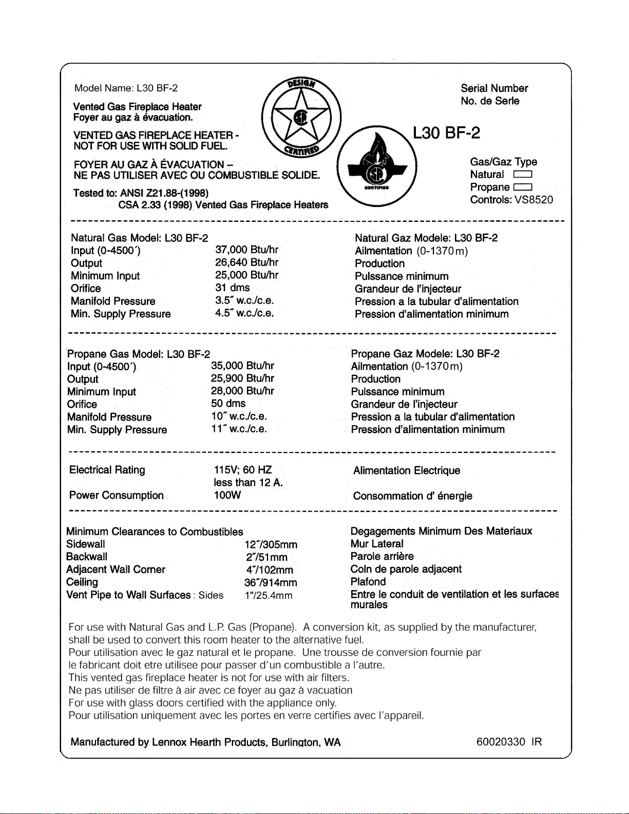
SAFETY / LISTING LABEL: Model L30 BF-2
PAGE 23
Page 24
OWNERSHIP RECORDS
Dealer’s Name:
Dealer’s Address:
City: State: Zip Code:
Serial Number: Date of Purchase: Date Installed:
Notes:
SERVICE AND MAINTENANCE LOG
Service Service Service
Date Technician Description
PAGE 24
Page 25

1110 West Taft Avenue
Orange, CA 92865
 Loading...