

Page 1

The Perfect Sound System for Your DVD Player
Just add your TV & DVD player; everything else is in the box
•
Incredible surround sound, perfect for DVD viewing & enhanced TV game experience
•
Also provides exceptionally great sound for your computer & MP3 player
•
Front panel audio input jack for MP3 & CD players
•
PLEASE READ CAREFULLY BEFORE USE
IB-HT3917-WM-E-041506
Page 2
WARNING
S3152A
TO PREVENT FIRE OR SHOCK HAZARD, DO NOT USE THE PLUG WITH
AN EXTENSION CORD, RECEPTACLE OR OTHER OUTLET UNLESS THE
BLADES CAN BE FULLY INSERTED TO PREVENT BLADE EXPOSURE. TO
PREVENT FIRE OR SHOCK HAZARD, DO NOT EXPOSE THIS APPLIANCE
TO RAIN OR MOISTURE. TO PREVENT ELECTRICAL SHOCK, MATCH WIDE
BLADE PLUG TO WIDE SLOT, FULLY INSERT.
CAUTION
RISK OF ELECTRIC SHOCK
The lightning flash with
arrowhead symbol, within an
equilateral triangle, is intended
to alert the user to the presence
of uninsulated “dangerous
voltage” within the product’s
enclosure that may be of
sufficient magnitude to constitute
a risk of electric shock to persons.
PLEASE NOTE: Caution mark is located on the bottom enclosure.
DO NOT OPEN
WARNING: TO REDUCE THE
RISK OF ELECTRIC SHOCK,
DO NOT REMOVE COVER (OR
BACK). NO USER SERVICEABLE
PARTS INSIDE. REFER
SERVICING TO QUALIFIED
SERVICE PERSONNEL.
The exclamation point within
an equilateral triangle is
intended to alert the user to
the presence of important
operating and maintenance
(servicing) instructions in the
literature accompanying the
appliance.
IMPORTANT SAFETY INSTRUCTIONS
1.Read these instructions. 2. Keep these instructions.
3.Heed all warnings. 4.Follow all instructions.
5.Do not use this apparatus near water. 6.Clean only with dry cloth.
7.Do not block any ventilation openings, install in accordance with the
manufacturer’s instructions.
8.Do not install near any heat sources such as radiators, heat registers,
stoves, or other apparatus (including amplifiers) that produce heat.
9.Do not defeat the safety purpose of the polarized or grounding-type plug. A
polarized plug has two blades with one wider than the other. A grounding
type plug has two blades and a third grounding prong. The wide blade or
the third prong are provided for your safety. If the provided plug does not fit
into your outlet, consult an electrician for replacement of the obsolete outlet.
10.Protect the power cord from being walked on or pinched particularly at plugs,
convenience receptacles, and the point where they exit from the apparatus.
11.Only use attachments/accessories specified by the manufacturer.
12.Use only with the cart, stand, tripod, bracket, or table
specified by the manufacturer, or sold with the apparatus. When
a cart is used, use caution when moving the cart/apparatus
combination to avoid injury from tip-over.
13.Unplug this apparatus during lightning storms or when unused for long
periods of time.
14.Refer all servicing to qualified service personnel. Servicing is required
when the apparatus has been damaged in any way, such as power-supply
cord or plug is damaged, liquid has been spilled or objects have fallen
into the apparatus, the apparatus has been exposed to rain or moisture,
does not operate normally or has been dropped.
15.This appliance shall not be exposed to dripping or splashing water and that
no object filled with liquid such as vases shall be placed on the apparatus.
16.Ventilation - Slots and openings in the cabinet and in the back or bottom are
provided for ventilation. To ensure reliable operation of protecting it from
overheating, these openings must not be blocked or covered. The openings
should never be blocked by placing the product on a bed, sofa, rug or other
similar surface. This product should never be placed near or over a radiator or
heat source. This product should not be placed in a built-in installation such
as a bookcase or rack unless proper ventilation is provided or the
manufacturer’s instructions have been adhered to.
Cleaning the Cabinet
Clean the cabinet and controls with a very dry or slightly moistened soft
cloth. Do not use any type of abrasive pad, scouring powder, or solvents,
such as alcohol or benzine.
Do not apply oil or petroleum products or solvents to any part of this set.
Please read important information displayed on
the rating plate located on the bottom enclosure
before connecting this set to AC power.
FCC NOTE
This equipment has been tested and found to
comply with the limits for a Class B digital
device, pursuant to Part 15 of the FCC rules.
These limits are designed to provide
reasonable protection against harmful
interference in a residential installation. This
equipment generates, uses and can radiate
radio frequency energy and, if not installed
and used in accordance with the instructions,
may cause harmful interference to radio
communications. However, there is no
guarantee that interference will not occur in a
particular installation. If this equipment does
cause harmful interference to radio or
television reception, which can be determined
by turning the equipment off and on, the user
is encouraged to try to correct the interference
by one or more of the following measures.
-Reorient or relocate the receiving antenna.
-Increase the separation between the equipment
and receiver.
-Connect this equipment into an outlet on a
circuit different from that to which the receiver
is connected.
-Consult the dealer or an experienced radio/
TV technician for help.
CAUTION
FCC Regulations state that unauthorized
changes or modifications to this equipment
may void the user’s authority to operate it.
PRECAUTIONS
ON SAFETY
Should any solid object or liquid fall into the
Home Theater System, unplug the player, and
have it checked by qualified personnel before
operating it any further.
ON PLACEMENT OF YOUR HOME
THEATER SYSTEM
Do not leave the Home Theater in a location
•
near a heat source, or in a place subject to
direct sunlight, excessively dusty rooms or
rooms with very high humidity.
Do not place the Home Theater system on
•
an inclined or unstable place.
Do not place anything within 1 inch of the sides
•
or 2 inches from the back of the cabinet. The
heat sink fins must not be covered for the
set to operate properly and prolong the life
of its components.
1
IB-HT3917-WM-E-041506
Page 3
Thank you for purchasing this 5.1 Channel Home Theater Surround Sound System. This deluxe audio theater system turns your
home into a virtual theater.
Basic Features & Benefits of this Home Theater System:
1.5.1 channel audio decoder for home theater surround sound.
2.Includes audio inputs for your DVD player and AUX (any audio device) and AUDIO INPUT jack on the front.
3.Powerful subwoofer provides real BOOM in your bass.
4.Deluxe easy-to-use remote control with batteries included.
5.Designed for easy, mistake-proof color-coded speaker setup.
6.Compatible with any computer sound system.
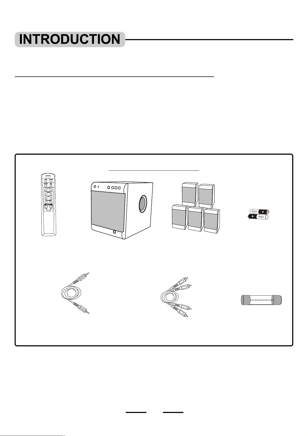
THIS SYSTEM CONTAINS
1 Remote Control
1 Set of Audio cables with green 3.5mm plug
for easy front panel connections to your
computer or MP3 (or any other Source
with a 3.5mm headphones Jack)
(with amplified Subwoofer)
1 Main Set
5 Satellite Speakers
1 Set of Audio Cables
for DVD or AUX IN
(Red & White)
2 “AAA” Batteries
(for remote control)
1 Spare Fuse
2
IB-HT3917-WM-E-041506
Page 4

• Getting Started
Safety Instructions-----------------------------------------------------------------------------------------------------------------------------------1
Introduction----------------------------------------------------------------------------------------------------------------------------------------------2
Location of Controls---------------------------------------------------------------------------------------------------------------------------------4
Remote Control Operation-------------------------------------------------------------------------------------------------------------------------6
• Connections
Speaker Connections--------------------------------------------------------------------------------------------------------------------------------7
Speaker Positioning Information---------------------------------------------------------------------------------------------------------------8
Audio Connections -----------------------------------------------------------------------------------------------------------------------------------9
• Basic Operation
General ---------------------------------------------------------------------------------------------------------------------------------------------------11
About fuse replacement----------------------------------------------------------------------------------------------------------------------------12
• Trouble Shooting ----------------------------------------------------------------------------------------------------------------------13
• Specifications -----------------------------------------------------------------------------------------------------------------------------14
3
IB-HT3917-WM-E-041506
Page 5
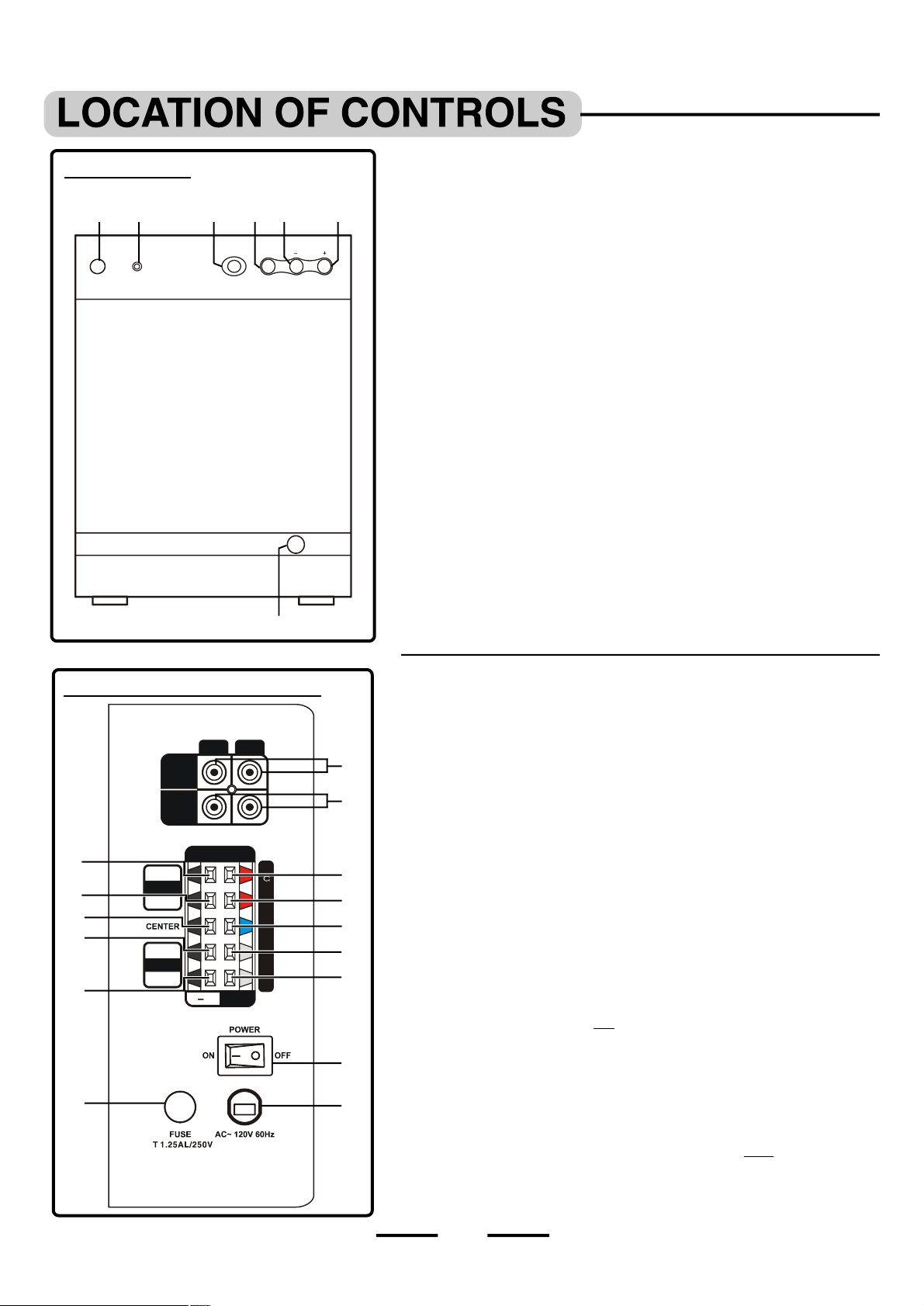
CONTROL PANEL
R
L
DVD IN
AUX IN
OUTPUT
LEFT
RIGHT
FRONT
RIGHT
+
ON
STANDBY
AUDIO IN
(ON THE FRONT OF THE SUBWOOFER)
2
1
4
3
SENSOR
SOURCE
1.ON/STANDBY button - In POWER ON mode, press to switch the set to on
or to standby mode.
5
6
VOLUME
2.ON/STANDBY indicator - This indicator flashes slowly in red when
the set is in the standby mode; Flashes in green confirming you pressed
any button on the main unit or on the remote control and is steadily on in
green when the set is on.
3.REMOTE SENSOR - Receives the signal from the REMOTE CONTROL
(aim the REMOTE control towards this sensor).
4.SOURCE button - Press repeatedly to select the sound input source:
DVD IN, AUX IN or AUDIO IN.
5.VOLUME – button - Decreases the volume level of all speakers.
6.VOLUME + button - Increases the volume level of all speakers.
7.AUDIO IN jack - This jack is for connecting your MP3 player to the set
with the included 3.5mm cable.
7
BACK OF MAIN SET (SUBWOOFER)
10
11
12
13
14
16
LEFT
REAR
SPE AKE R TERM INA LS 4
8
9
10
11
12
13
14
15
17
8.DVD IN jacks - Connect to the audio output of a DVD player for surround
sound.
9.AUX IN jacks - Connect to the audio output of a tape deck, TV game,
video camera or other component’s audio output.
10.FRONT LEFT SPEAKER jacks - Connect the FRONT LEFT SPEAKER
to the red and black terminals.
11.FRONT RIGHT SPEAKER jacks - Connect the FRONT RIGHT SPEAKER
to the red and black terminals.
12.CENTER SPEAKER jacks - Connect only the CENTER SPEAKER to the
blue and black terminals.
13.REAR LEFT SPEAKER jacks - Connect the REAR LEFT SPEAKER
to the grey and black terminals.
14.REAR RIGHT SPEAKER jacks - Connect the REAR RIGHT SPEAKER
to the grey and black terminals.
15.POWER switch - Press to power the set on or off.
NOTE: This switch must be ON in order to be able to use the ON/STANDBY
button on the main set or on the REMOTE CONTROL.
16.FUSE HOLDER with screw cover.
17.AC LINE CORD - Connect to a 120V/60Hz AC standard wall outlet.
IMPORTANT:
Each speaker must be connected to 1 colored terminal AND 1 black terminal.
4
IB-HT3917-WM-E-041506
Page 6

REMOTE CONTROL
5
1.IR DIODE - Sends the signal to the set. Do not block or cover this.
2.ON/STANDBY button - Switches the player from STANDBY to ON
or ON to STANDBY (if the main POWER of the set is ON).
1
3.SOURCE button - Press to select the sound input source you want:
2
3
DVD IN, AUX IN or AUDIO IN.
4.RESET button - Press to adjust all speakers’ output to the factory’s
default settings.
10
46
5.MUTE button - Instantly turns off the sound. Press again to restore the
sound.
7
8
6.CHANNELS button - Press to select 2.1 channel or 5.1 channel
listening mode.
7.FRONT UP & DOWN VOLUME buttons - Press to adjust the individual
9
FRONT LEFT/RIGHT speakers’ sound level.
8.CENTER UP & DOWN VOLUME buttons - Press to adjust the
individual CENTER speaker’s sound level.
11
9.REAR UP & DOWN VOLUME buttons - Press to adjust the REAR
LEFT/RIGHT speakers’ sound level.
10.SUBWOOFER UP & DOWN VOLUME buttons - Press to adjust the
individual SUBWOOFER’s sound level.
11.MASTER VOLUME UP & DOWN buttons - Press to adjust the sound
level of all speakers at the same time.
SEE NEXT PAGE FOR REMOTE CONTROL BATTERY INSTALLATION.
5
IB-HT3917-WM-E-041506
Page 7

Battery Installation Remote Control Operating Range
STANDBY
30o30
+
_
_
Point the REMOTE CONTROL unit within 20 feet from the
remote control sensor and facing the front of the HOME
1.Gently push the door and slide to open the BATTERY
DOOR.
2.Insert 2 size “AAA” alkaline batteries (included) into the
battery compartment according to the “ + ” and “ – ”
markings inside the battery compartment.
THEATER SYSTEM.
REMOTE CONTROL RANGE
SENSOR
SOURCE
ON
VOLUME
o
Remember: The spring touches the “ – ”
side of each battery.
3.Replace the battery compartment door.
Tips on Battery Use
Reversing polarities will damage the batteries and possibly
•
your REMOTE. Be sure to follow polarity “ + ” and “ – ” as indicated.
Do not mix different types of batteries together (Alkaline,
•
Carbon-Zinc, Nickel-Cadmium etc.), or old batteries with new
ones.
When not in use for an extended period of time (over 30
•
days), remove the batteries to prevent possible acid leakage
or corrosion resulting in possible damage to your REMOTE
CONTROL.
When the batteries have become discharged, they must be
•
disposed of in a safe manner that complies with all applicable
laws.
Installation of batteries should only be done by an adult
•
(for safety).
WARNING:
The batteries (battery pack or batteries installed) shall not be
exposed to excessive heat such as sunshine, fire or the like.
Distance within 20 feet
Remember to point the
REMOTE CONTROL in
the direction of the HOME
THEATER’s sensor, not
the TV set or the DVD
player.
Point the REMOTE CONTROL at the
Home Theater’s Front
Make sure there is a clear path between the REMOTE
CONTROL and the HOME THEATER SYSTEM so that the
signal is not blocked.
Tips on REMOTE CONTROL Operation
The REMOTE control’s operating distance may vary
•
according to the brightness of the room.
Do not point bright lights at the REMOTE CONTROL
•
SENSOR (like laser pointers).
Do not place objects between the REMOTE CONTROL unit
•
and the REMOTE SENSOR.
Do not use this REMOTE CONTROL while simultaneously
•
using the remote control unit of any other equipment, the
signals may mix.
Sometimes your TV’s remote may cause an LED to flash,
•
you can ignore this.
6
IB-HT3917-WM-E-041506
Page 8
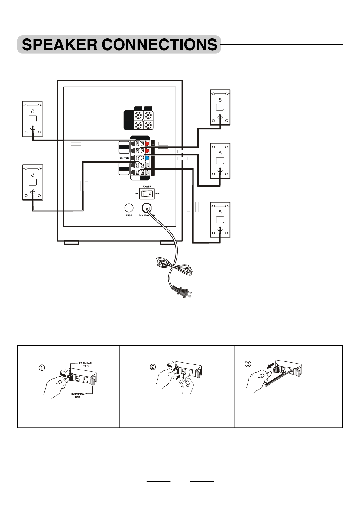
Connect the supplied speaker system by matching the colors of the terminals to those of the cords. The speaker wires and connectors
R
L
DVD IN
AUX IN
OUTPUT
RIGHT
FRONT
RIGHT
FRONT RIGHT
BLACK
BLUE
BLACK
GREY BLAC
K
T 1.25AL/250V
are color-coded for easier set up.
FRONT LEFT
SPEAKER
REAR LEFT
SPEAKER
BLACK
RED
SPEAKER
NOTE:
Connect the Front Left speaker to
•
the Front Left terminals (red + black).
Connect the Front Right speaker to
•
the Front Right terminals (red + black).
Connect the Center speaker to the
•
Center speaker terminals (blue + black).
Connect the Rear Left speaker to
•
LEFT
CENTER
RED
SPEAKER
the Rear Left terminals(grey + black).
LEFT
REAR
GREY
BLACK
SPEA KER TERM INALS 4
+
REAR RIGHT
SPEAKER
Connect the Rear Right speaker to
•
the Rear Right terminals (grey + black).
IMPORTANT:
1.Before making connections, make
sure the power is off.
2.Be sure you are using the correct
satellite speaker in each location,
front, rear and center.
3.Each speaker must be connected
to 1 colored terminal AND 1 black
terminal.
4.Match the colors of the wires to the
colors of the terminals.
Tips for connecting the speaker wires
Unwind and stretch out the speaker wires attached with each speakers, then push and hold down the set terminal tab on the back of the
main set to insert each wire. Make sure the wire is fully inserted, but the insulation is not covering the inserted part of the speaker wires.
SET TERMINALS
PUSH AND HOLD THE TAB OF
TERMINAL.
WHILE HOLDING THE TAB OF THE TERMINAL,
STICK THE EXPOSED PART OF THE WIRE
INTO THE HOLE OF THE TERMINAL.
SET TERMINALS
REMOVE YOUR FINGER FROM THE
TERMINAL TO LOCK THE WIRE INSIDE
THE TERMINAL.
GO ON TO THE NEXT WIRE & REPEAT ABOVE. MAKE SURE POWER IS OFF WHEN DOING THE ABOVE.
NOTE: Be sure to match the speaker wire to the appropriate terminal on the back of the main set: (+ ) to (+) (color), and (– ) to (– ) (black).
If the wires are reversed, the sound will be distorted and will lack some tones. Follow the color codes of each of the terminals.
7
SET TERMINALS
COLORED WIRE TO COLORED
TERMINAL, BLACK WIRE TO
BLACK TERMINAL.
IB-HT3917-WM-E-041506
Page 9

To avoid short-circuiting the speakers
Front-right
YOUR TV SET
Make sure the stripped end of each speaker wire does not touch another speaker terminal or the stripped end of another speaker wire.
Examples of poor connection of the speaker wires
LOOSE WIRE STRAND TOUCHING (This will short out the sound)
• Stripped speaker wire is touching another set terminal.
Make sure not even 1 strand of wire touches the other wire!
MAKE SURE THE ABOVE DOES NOT HAPPEN
NOTE: If longer wires are needed, you may buy any good quality speaker wire and splice the wires yourself. Please make sure the
wires are not shorting to each other and observe the correct color polarity.Many speaker wires have a dotted line or solid line
or raised rib on one side to identify each side. Also make sure you use electrical tape to cover your splices.
Proper positioning and placement of the speakers and the subwoofer are important to provide the best surround sound experience,
for optimal listening experience, position them as below.
Front-left
WIRES SHORTED TO EACH OTHER (This will short out the sound)
• Stripped wires are touching each other due to excessive removal of
insulation. Do not allow the above to happen on your set.
Center
Subwoofer
Rear-left
OR
LISTENING
POSITION
The 4 satellite speakers and the center speaker should be placed approximately the same distance from your
•
listening position.
The center speaker should be placed directly above (or below) the TV set. The left and right front speakers
•
should be approximately at the same height as the center speaker.
The rear speakers should be either in line with, or behind your listening position, approximately at ear level, or
•
slightly above.
The subwoofer (main set) should be on the floor near the TV, or in any corner, but remember you need a clear
•
path toyour remote (don’t block this set with a curtain).
All speakers must be visible. Do not hide them behind curtains, furniture, etc, as this will affect the sound.
•
You may only place the center speaker (blue wire) or the front speakers (red wires) near or above the TV set
•
because these speakers are magnetically shielded.
We have provided one keyhole opening on the backs of all the satellite speakers that allow the satellite speakers
•
to be wall mounted in a vertical position.
OR
Rear-right
OR
NOTE: You may only place the CENTER speaker (blue wire) or the FRONT speakers (red wires) on or near your TV set or
computer monitor. These speakers have magnetic shielding inside. If you put the REAR speakers near your TV set or
computer monitor, the colors on your TV or computer monitor may change due to magnetism.
8
IB-HT3917-WM-E-041506
Page 10

YOUR TAPE RECORDER/PLAYER
YOUR AM/FM TUNER
OROROR
Home Theater System + Tape Recorder/Player / AM/FM Tuner + TV
YOUR DVD, VCR, TV GAME OR VIDEO CAMERA
BACK OF YOUR TV SET
TV GAME OR VIDEO CAMERA
RL
DVD IN
AUX IN
R and L stand for RIGHT channel and LEFT channel
YOUR TV SET
This will allow the sound of the tape recorder/player, AM/FM tuner or TV to be played through the HOME THEATER SYSTEM.
Home Theater System + TV + DVD Player / VCR / TV Game / Video Camera
DVD IN
AUX IN
RL
AUDIO OUT
R
1
DVD OR VCR
2
VIDEO OUT
L
This will allow the sound of DVD, VCR, TV game, or video camera to be played through the HOME THEATER SYSTEM and the
picture to be displayed through your TV.
9
IB-HT3917-WM-E-041506
Page 11

Home Theater System + TV + Satellite
SATELLITE RECEIVER / CABLE BOX
OR
YOUR CD/MP3 PLAYER, RADIO, COMPUTER
OR OTHER SOURCE WITH 3.5MM STEREO JACK
YOUR
COMPUTER
OROR(3.5mm plug)
SATELLITE INOUT TO TV
CABLE OR ON AIR ANTENNA/
SATELLITE SIGNAL
DVD IN
AUX IN
RL
VIDEO
IN
ANT IN
AUDIO OUTPUT
RF (coaxial) cable unchanged,
same as before
This will allow the sound of satellite to be played through the HOME THEATER SYSTEM, and you will hear the sound from both
the TV and the HOME THEATER SYSTEM, this is normal.
Home Theater System + CD / MP3 / PC / Radio or other Source with 3.5mm Stereo
Jack
OR
GREEN
(3.5mm plug)
This will allow the sound of CD/MP3 player, radio, computer or other source with 3.5mm stereo jack to be played through the
HOME THEATER SYSTEM.
10
IB-HT3917-WM-E-041506
Page 12

R
L
DVD IN
AUX IN
OUTPUT
RIGHT
FRONT
RIGHT
T 1.25AL/250V
General
ON/STANDBY
button
ON/STANDBY
indicator
Remote
sensor
SOURCE
button
MASTER VOLUME
buttons
LEFT
LEFT
REAR
POWER switch
AC power plug
SPEA KE R TE RMI NAL S 4
+
1 After completing all SPEAKER and AUDIO connections, plug the AC power plug into a 120V 60 Hz wall outlet and flip POWER
switch on the back of the main set to ON position, the system enters STANDBY mode and the ON/STANDBY indicator will flash
in red. This plug is polarized, if it does not fit your outlet, do not force it, reverse it and re-insert it.
2 Press the ON/STANDBY button on the front of the main set or on the REMOTE CONTROL to turn the system on and the
ON/STANDBY indicator will be steadily on in green.
NOTE: The ON/STANDBY indicator has 3 modes: flashing in red and in green, and steadily on in green (slow flashing in red
indicates the set is in standby mode; Flashing in green indicates confirming you pressed any button on the main set or on the
remote control and steadily on in green indicates the set is on). When the set is on, pressing the ON/STANDBY button on the
main set or on the REMOTE CONTROL will turn the set to the standby mode, the indicator will become slow flashing in red.
3 Press the SOURCE button on the front panel of the main set or on the REMOTE CONTROL repeatedly to select your desired audio
input sources and the sound will be heard from the HOME THEATER SYSTEM.
4 For SUBWOOFER’s volume adjustment, press the SUBWOOFER volume control buttons on the Remote control:
+ raises the volume, and the ON/STANDBY indicator will flash in green, but at its maximum level, the ON/STANDBY indicator will
stop flashing.
– lowers the volume, and the ON/STANDBY indicator will flash in green, but at its minimum level, the ON/STANDBY indicator will
stop flashing.
Follow this step to adjust the FRONT, CENTER and REAR speakers as well.
5 For MASTER’s volume adjustment (change all the speaker’s volume at the same time), press the VOLUME + or VOLUME –
button on the main set or the MASTER VOLUME control or on the remote control.
raises the volume, and the ON/STANDBY indicator will flash in green, but at its maximum level, the ON/STANDBY indicator
will stop flashing.
lowers the volume, and the ON/STANDBY indicator will flash in green, but at its minimum level, the ON/STANDBY indicator
will stop flashing.
6 To adjust all speaker’s volume to the factory’s default settings, press the RESET button.
NOTE: Every time you turn the set on, the MASTER VOLUME will go back to the factory’s default setting; and whenever you
press the SOURCE button on the main unit or the SOURCE button on the REMOTE, the MASTER VOLUME will go
back to the factory’s default setting. This avoids sudden very loud sounds from startling you.
11
IB-HT3917-WM-E-041506
Page 13

7 To momentarily shut off the sound, press the MUTE button and the ON/STANDBY indicator will flash in green continuously. Press
the MUTE button again or press the MASTER VOLUME buttons to restore the sound and the ON/STANDBY indicator will stop
flashingand be steadily on in green.
8 To select the listening mode, press the CHANNELS button on the REMOTE CONTROL.
NOTE: The factory’s default input source is DVD with 5.1 channel sound output. When the set is turned to ON,the sound will
come out of 5 speakers plus the subwoofer. To change 5.1 channel to 2.1 channel output, press the CHANNELS button. The
sound will come out of only 2 front speakers plus the subwoofer, the center and rear speaker volume controls will, of
course, not work.
NOTE 1: The system has an automatic volume protection function, for safety and reducing the distortion. When the output volume is
raised too high, the system will automatically adjust the volume to the proper level, and the ON/STANDBY indicator will
flash in green.
NOTE 2: Flip the POWER switch on the back of the main set to OFF position if the set will not be used for a long period of time
(several days or more). Remember to flip it back ON again before use.
About fuse replacement.
NOTE: Before attempting to change the fuse, the system must be unplugged from the wall outlet.
In the unusual event that nothing lights up and no sound, your fuse may have blown. To check for a blown fuse, follow the steps below.
GOOD FUSE BLOWN FUSE
1. Open the fuse cover (on the back of
the main set) by using a flat blade
screwdriver to unscrew the fuse
cover cap.
2. Examine the fuse. If a wire
shows, the fuse is good.
3. If the wire is broken in the middle,
replace with a 1.25AL 250V “T” type
glass fuse.
“T” means time delay or slow blow
fuse.
12
IB-HT3917-WM-E-041506
Page 14

Symptom
No power.
Your DVD player has no picture.
No sound or only a very low-level
•
sound is heard.
Distorted sound.
•
Remedy
1.Is the power cord firmly plugged into the power outlet? Insert the AC power
plug securely into the power outlet. Make sure your outlet has power, you
can check this by plugging a lamp into the outlet to see if it works.
2.Is the main power switched to off? Flip it to ON.
3.One of the safety mechanisms may be operating. In this event, unplug the
player from the power outlet briefly and then plug it in again to reset the set.
4.Your set’s fuse may have blown.
5.Unscrew the fuse cover & check the fuse.
6.Replace only with same 1.25AL slow blow 250V “T” type glass fuse. See page 12
for more information.
Make sure your DVD’s video cable is plugged into your TV set. This Home Theater
only improves the sound of your DVD player, it does not affect the video at all. Also
select the correct VIDEO INPUT on your TV.
1.Check that the speakers and components are connected securely and
correctly, make sure the stripped end of each speaker wires does not touch
each other to avoid short-circuit of the speaker wires (see Pages 7 & 8). Also
check speaker volume (see Pages 11 & 12).
2.Make sure your source (DVD or other) is plugged in and operating. Also
check that component’s booklet, maybe you need adjust that component.
3.Check and make sure your DVD’s sound output is set to analog. For some DVDs,
if the sound output is not set to analog, the audio cables may not be active and
there will be no sound output.
4. Make sure that you have selected the correct source on the system (DVD or other
source, according to which audio input jacks are connected).
5.Adjust the set’s MASTER volume or the SUBWOOFER’s volume settings on the front
of the HOME THEATER or on the remote, also adjust the volume of the input source.
6.Ensure the MUTE button is not pressed on the HOME THEATER remote (If
yes, press theMUTE button again).
7.The audio or speaker connecting wires are damaged. Replace them with new ones.
The REMOTE CONTROL unit does not
work.
No buttons operate (on the main set
and / or the REMOTE CONTROL unit).
The left and right sounds are unbalanced
or reversed.
Rear speakers and center speaker cannot be adjusted individually.
Loud hum or noise is heard.
No sound is heard from the center
speaker.
The system does not operate properly.
1.Check if the batteries are installed with the correct polarities (+ and –).
2.If the batteries are weak or dead, replace them with new ones (size “AAA”).
3.Point the remote control unit at a distance of less than 20 feet from the main
unit of the HOME THEATER system.
4.Remove any obstacles between the remote control unit and remote control sensor.
5.If the battery terminals are dirty or corroded, clean them with sandpaper.
Press the POWER button on the back of the MAIN SET to turn the set ON. Then
press the ON/STANDBY button on the main set or on the REMOTE. The HOME
THEATER may not be operating properly due to lightning, static electricity, or
some other external factors. Reset the player by disconnecting the power plug
and then re-connecting it before calling customer service. Also check the Fuse.
See page 12.
Check that the speakers and components are connected correctly and securely.
During 2.1 channel operation, these speakers cannot be adjusted individually,
you can raise or lower the volume level of the whole set by pressing the
MASTER VOLUME + or – button. To adjust these speakers individually, set to 5.1
channel sound output mode.
1.Check that the speakers and components are connected securely.
2.Insert all wires firmly, follow the pages 7 & 8.
Loud hum usually means a plug is not fully seated into the jack.
1.Make sure the Center speaker’s volume is set to a normal level (see Page 11).
2.Adjust the center speaker volume by pressing the volume control buttons of
the center speaker on the REMOTE (see Page 11).
3.If you are listening to 2.1 channel output mode, only 2 front speakers plus the
subwoofer will have sound.
Double check if input & output jacks were inserted properly. Also ask a friend to
help you before calling customer service.
13
IB-HT3917-WM-E-041506
Page 15

General
Power requirements -----AC 120V, 60Hz
Power consumption ------60 Watts
Main set Dimensions ----6 7/8 x 9 1/4 x 11 1/2 inches / 17.4 x 23.5 x 29.2 cm
Weight -----------------------7.7 lbs / 3.5 kg
Audio Power Output
Total output power:40Watts (THD 10%), 60 Watts (Maximum)
Distortion
0.06% @ reference output
Remote Operating Range
Within 20 feet between the main set and the remote.
Replacement Fuse
Time delay 1.25 Amp T type (slow blow) glass fuse 250V.
Speakers
Front Left -------------------Dimensions: 3 1/8 x 3 1/8 x 5 5/8 inches / 7.9 x 7.9 x 14.3 cm
Weight: 0.86 lb / 0.39 kg (Red Terminals)
Center -----------------------Dimensions: 3 1/8 x 3 1/8 x 5 5/8 inches /7.9 x 7.9 x 14.3 cm
Weight: 0.86 lb / 0.39 kg (Blue Terminals)
Front Right -----------------Dimensions: 3 1/8 x 3 1/8 x 5 5/8 inches / 7.9 x 7.9 x 14.3 cm
Weight: 0.86 lb / 0.39 kg (Red Terminals)
Rear Left -------------------Dimensions: 3 1/8 x 3 1/8 x 5 5/8 inches / 7.9 x 7.9 x 14.3 cm
Weight: 0.86 lb / 0.39 kg (Grey Terminals)
Rear Right -----------------Dimensions: 3 1/8 x 3 1/8 x 5 5/8 inches / 7.9 x 7.9 x 14.3 cm
Weight: 0.86 lb / 0.39 kg (Grey Terminals)
We reserve the right to make design and specification changes for product improvement.
The descriptions and characteristics given in this document are given as a general indication and not as a guarantee. In order
to provide the highest quality product possible, we reserve the right to make any improvement or modification without prior
notice. The English version serves as the final reference on all product and operation details should any discrepancies arise in
other languages.
PROTECT YOUR FINE FURNITURE!
WE RECOMMEND A CLOTH OR OTHER PROTECTIVE MATERIAL BE PLACED UNDER THE SET OR SPEAKERS WHEN
PLACING IT ON A SURFACE WITH A NATURAL OR LACQUER FINISH.
LIMITED WARRANTY
We warrant this product to be free from defects in material and workmanship under normal use for a period of 1 year after
purchase, and we will repair it free of charge or replace it at no charge, should it become defective under this warranty, providing you
submit proof of purchase (sales slip) with the set.
During the initial 1 year period after original purchase, we will service the set that is returned to LENOXX ELECTRONICS CORP.,
prepaid, at no charge. After the initial 1 year period expires, we will exchange, at no charge, any part that is defective, but will charge
for the cost of labor, return postage paid by Lenoxx.
This warranty does not apply to any product which has been subject to misuse, neglect or accident. This warranty does not cover
a broken cord or cabinet. UNDER NO CIRCUMSTANCES WILL LENOXX ELECTRONICS CORP. BE LIABLE FOR ANY INCIDENTAL
OR CONSEQUENTIAL DAMAGES. Some states do not allow the exclusion or limitation of incidental or consequential damages, so
the above limitations or exclusions may not apply to you.
This warranty gives you specific legal rights, and you may also have other rights which vary from state to state. The following
charges apply to repairs beyond the warranty period: $ 20.00. Be sure to pack carefully and return postage paid insured together with
your money order (personal checks will not be accepted) and sales receipt to:
LENOXX ELECTRONICS CORP., 35 BRUNSWICK AVENUE EDISON, N.J. 08817. USA
For Customer Service
Dial: 1-800-315-5885 (MONDAY - THURSDAY 8:00 AM - 5:00 PM, FRIDAY 8:00 AM - 1:30 PM EST)
or Visit Our Website: http://www.lenoxx.com
or Email: evergo@att.net
© 2006 LENOXX ELECTRONICS CORP.
35 BRUNSWICK AVENUE
EDISON, N.J. 08817. USA
MADE & PRINTED IN CHINA
14
IB-HT3917-WM-E-041506
 Loading...