

Page 1
AM / FM ANTENNAS
AM ANTENNA
IMPORTANT!
• Before connecting the AC power cord to the wall outlet, ensure that all other connections have been made.
• Never make or change any connections with the power switched on.
• The type plate is located at the rear of the system.
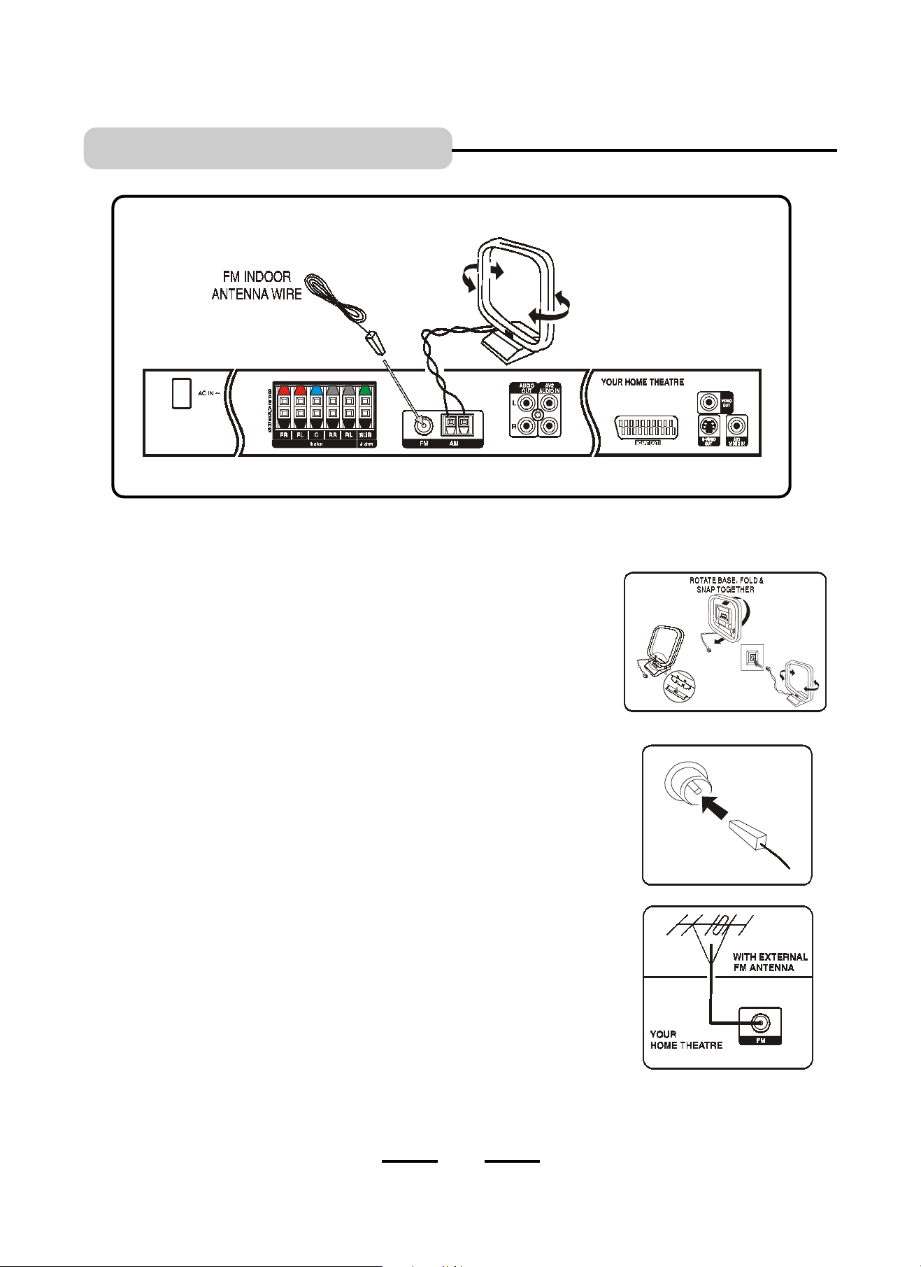
Connecting antennas
AM Indoor Loop Antenna
Connect the supplied AM loop antenna to the AM antenna terminals. Position the loop
antenna to receive the clearest sound. You may insert either wire into either connector, the
base of the AM antenna folds up to form a small platform for this loop antenna.
FM Indoor Antenna
Connect the supplied FM antenna wire to the FM terminal. Just insert the plastic piece of the
FM indoor antenna into the FM connector. Move the antenna in various directions until the
clearest signal is received.
Note: Keep this FM antenna as far away as possible from the TV, VCR or any radiation
source to prevent possible unwanted noise.
FM Outdoor Antenna
For better FM reception, use a 75 ohm coaxial cable (not supplied) to connect the system
to an outdoor FM antenna as shown.
Insert your antennas connector into the FM antenna connector on the back of the set.
You may need a signal splitter and extra cable if your outdoor antenna is already connected
to your TV or VCR.
INSERT THE FM
INDOOR ANTENNA
10
IB-HT600-SW-E-031503
Page 2
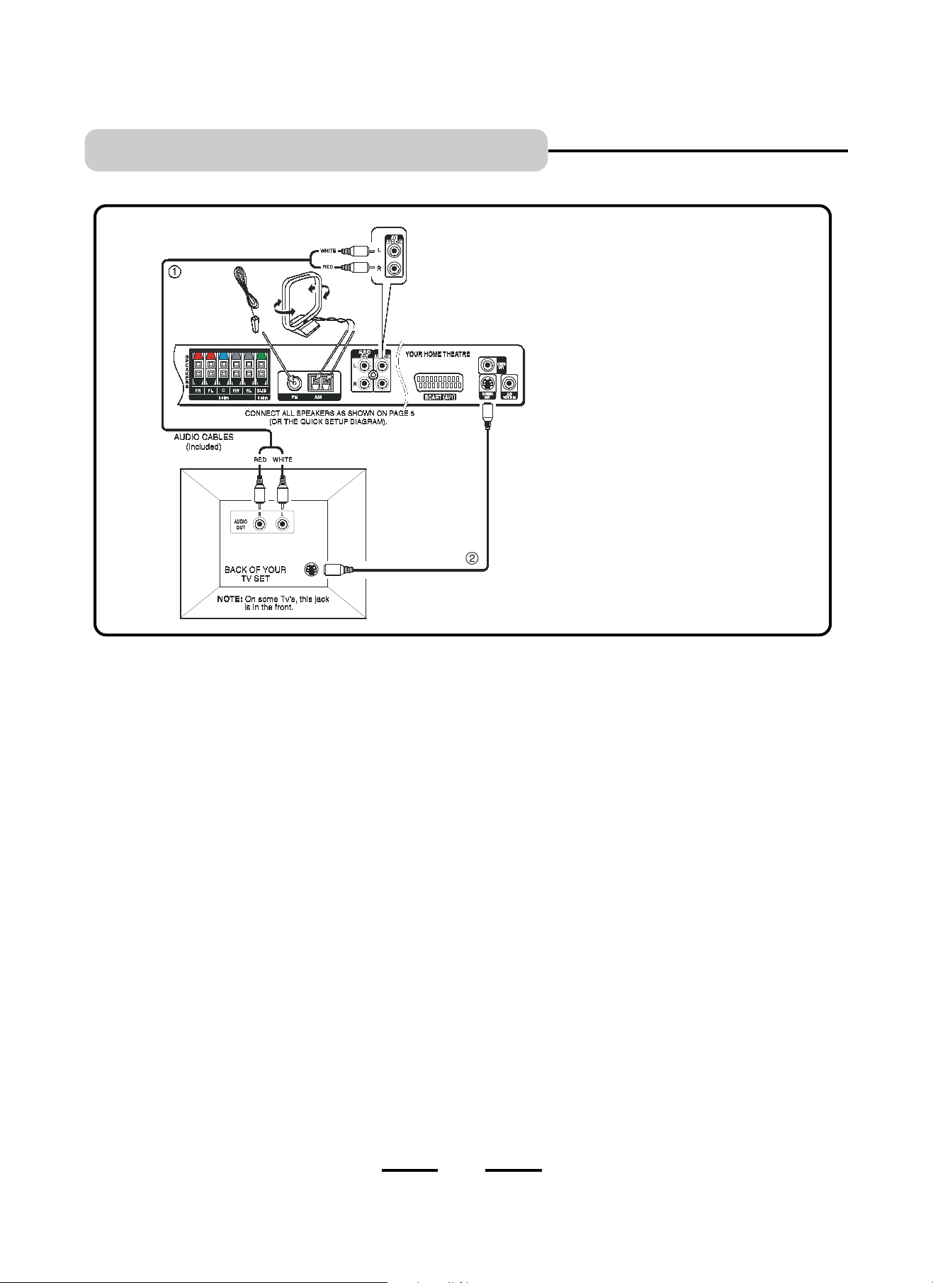
TV CONNECTION - S-Video
DVD Home Theatre System + TV with Audio/Video Input Jacks and S-Video Jack
S-Video cable (cable not
included) provides a sharper
picture than normal video. Use an
S-Video cable if your TV has an
S-Video jack. (But no SCART jack)
NOTE: Yellow Video plug and wire are not used
when useing S-Video or SCART. If your TV has
no SCART or S-Video jack, use the VIDEO IN
jack and cable as shown on Page 9.
1. Insert the audio cables into the AUDIO OUT L (left=white) and R (right=red) jacks on the back of your TV set, and
into the corresponding AV2 AUDIO IN jacks on your DVD HOME THEATRE. This will enable you to hear your
regular TV shows through your DVD HOME THEATRE SYSTEM when not playing DVDs. (This is optional, you
do not need to do this step if your TV set has good sound.)
NOTE: On some TVs, the AUDIO OUTPUT jacks may have no signal. On those TVs, you may activate these
jacks by using your TVs REMOTE (not the CABLE or SATELLITE remote) and selecting the correct AUDIO
OUT (on some TVs, select AUDIO OUT to fixed). Please see your TVs manual for details.
NOTE: The TV sound will come out of 5 speakers plus subwoofer since the factorys default setting
for the sound output is PRO LOGIC. Press the SURROUND button if you want to return to STEREO
sound output, and the sound will only come out of 2 speakers plus subwoofer.
2. Insert the S-Video cable into the S-VIDEO OUT jack on the back of your DVD HOME THEATRE SYSTEM and to
the S-VIDEO jack on your TV. This connection will allow you to enjoy higher quality images. If your TV doesnt
have S-VIDEO, use the basic video connection listed on Page 9 (yellow plugs: VIDEO IN or OUT, are not
needed for S-Video, but needed only if your TV set does not have an S-Video jack or you may use a SCART
cable. However, the sharpest TV picture is with SCART cable).
3. Insert the AC power cord into an AC socket.
4. Press the POWER button on the main unit.
5. Select your TVs video channel (see page 23).
6. Go to Page 25 for playing DVDs (discs).
NOTE: Your cable or antenna connection to the television will not be affected by this connection. Connect your
antenna cable to your television as you normally would. You may need to consult your television manual
for details, but no changes will be made to your current antenna connections.
ANTENNAS:
1. Your cable or antenna connection to the television should not be affected by this connection. Connect your
antenna cable to your television as you normally would. You may need to consult your television manual for
details, but no changes will be made to your current antenna connections.
2. For the home theatre antenna connections, we supply an AM loop antenna. Connect this to the AM terminals.
3. For the FM antenna, you may use the PIG TAIL antenna we supplied or you may use an antenna
splitter & cable to connect an outdoor antenna to the FM antenna on the back of your set. Better FM reception will
probably be received with an outdoor FM antenna.
11
IB-HT600-SW-E-031503
Page 3
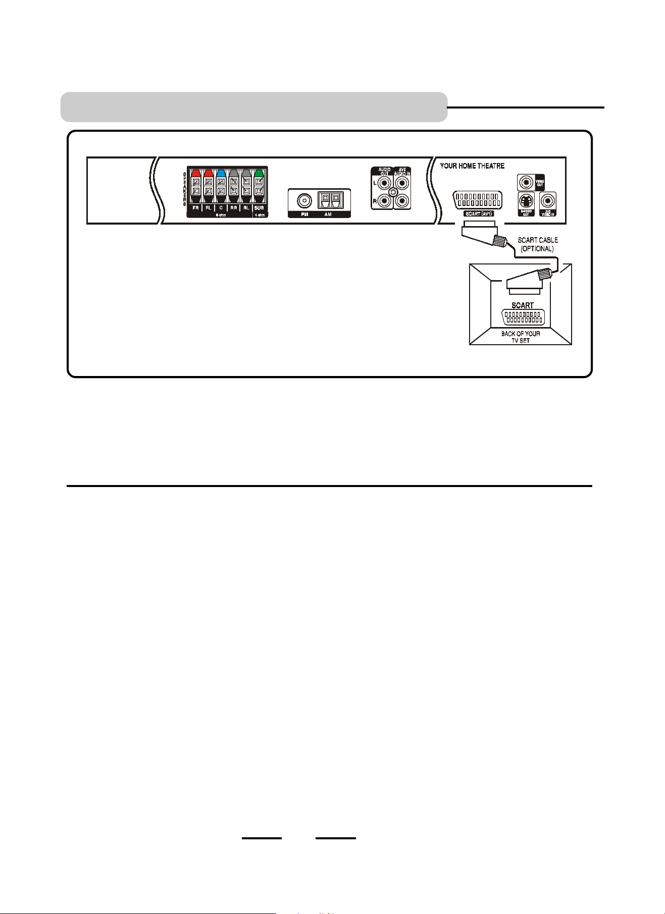
TV CONNECTION - WITH SCART
NOTE: When useing the SCART cable, no
yellow video cable is needed, also the
audio cables (red & white) are not needed.
The SCART cable contains both Audio &
Video cables inside.
NOTE: The sharpest and best picture is with a SCART cable.
1. Connect the 5 satellite speakers and subwoofer as shown on Page 5 (or the QUICK SETUP DIAGRAM packed
with the set).
2. Connect the AM loop & FM indoor antenna as shown on page 9.
3. Insert the one end of the SCART cable into the SCART(AV1) jack on the back of your DVD HOME THEATRE
SYSTEM, and the other end into the corresponding SCART IN jack on your TV set.
4. Insert the AC power cord into an AC socket.
5. Select your TVs video channel (see page 23)
6. Go to Page 25 for playing DVDs (discs).
ANTENNAS: 1. Your cable or antenna connection to the television should not be affected by this connection. Connect
your antenna cable to your television as you normally would. You may need to consult your television
manual for details, but no changes will be made to your current antenna connections.
2. For the home theatre antenna connections, we supply an AM loop antenna. Connect this to the AM
terminals.
3. For the FM antenna, you may use the indoor wire antenna we supplied or you may use an antenna
splitter & cable to connect an outdoor antenna to the FM antenna terminal on the back of your set.
Better FM reception will probably be received with an outdoor FM antenna.
12
IB-HT600-SW-E-031503
Page 4

TV + VCR CONNECTIONS
1. Insert a set of stereo audio cables (optional, not included) into the HOME THEATRE AV2 AUDIO INPUT L (Left=White)
and R (Right=Red) jacks and into the corresponding AUDIO OUT jacks on your VCR, this will allow your VCRs sound
to play through your HOME THEATRE SYSTEM.
NOTE: Your VCR stereo sound will come out of 5 speakers plus subwoofer since the factorys default
setting for the sound output is PRO LOGIC. Press the SURROUND button if you want to return to STEREO
(2 channel) sound output, and the sound will only come out of 2 speakers plus subwoofer (Probably best for
VCR sound).
2. Insert the video cable (yellow) into the VIDEO OUT jack on the back of your VCR player, and into the AV2 VIDEO
IN jack on your HOME THEATRE.
3. Then connect a Video cable from the HOME THEATRE VIDEO OUT terminal to your TVs VIDEO IN terminal.
4. OR connect your VCR with your TV useing a coaxial antenna cable. Or see alternate connection below.
5. Connections of your other antenna cables are not changed when you add your DVD HOME THEATRE SYSTEM.
6. Insert the AC power cord into an AC socket.
7. Select your TVs video channel or previously used VCR viewing
channel. (see Page 23).
connect the VCRs VIDEO OUTPUT directly
8. Go to Page 25 for playing DVDs (discs).
13
ALTERNATE CONNECTION
On some sets it may be better for you to
to your TVs VIDEO IN.
IB-HT600-SW-E-031503
Page 5

TV / VCR COMBINATION CONNECTIONS
IF YOU OWN A TWO-IN-ONE COMBINATION TV/VCR
NOTE:
A Video RF Modulator is
needed for any TV/VCR
combined set which does
not have VIDEO & AUDIO
inputs jacks or a SCART
jack. Some TV/VCR sets
have VIDEO & AUDIO
inputs. For these sets you do
not need an RF Modulator.
The signal provided by an
RF modulator is never as
sharp as a direct connection
into a TV with a VIDEO input
jack or SCART jack.
1. Insert the RF Modulators antenna cable (not included) into the ANTENNA jack on the back of your TV/VCR
player, and to the TV OUT jack of your VIDEO RF MODULATOR.
2. Connect the video cable (yellow) to the VIDEO OUT jack on the back of your DVD HOME THEATRE SYSTEM, and
into the VIDEO IN jack on your VIDEO RF MODULATOR.
3. Insert the AC power cord into an AC socket. Press your TVs video channel to match the RF Moudulators channel.
4. Press the POWER button on the main unit.
5. Select your TVs Video channel to match your RF Modulators Video channel (usually 3 or 4).
6. Go to Page 25 for playing DVDs (discs).
14
IB-HT600-SW-E-031503
Page 6

TV + VCR + SATELLITE RECEIVER CONNECTIONS
1. Follow the above connection diagram and check if you have these items. If your VCR has AUDIO OUT jacks, you may
connect your VCR to your DVD HOME THEATRE as shown.
2. Insert the video cable (yellow) into the VIDEO OUT jack on the back of your DVD HOME THEATRE SYSTEM, and into
the VIDEO IN jack on your TV.
3. Use an antenna cable to connect the antenna output on the satellite receiver to the antenna input on the VCR the
same as you have it connected now. This DVD HOME THEATRE SYSTEM does not change any antenna connections.
4. Insert the AC power cord into an AC socket.
5. Press the POWER button on the main unit.
6. Select your TVs video channel (see page 23).
7. Go to Page 25 for playing DVDs (discs).
15
IB-HT600-SW-E-031503
Page 7

AUX IN (AV2) CONNECTIONS
Illustration shows some possible
connections. You can only connect
ONE of these to the AV2 AUDIO IN
jacks of your HOME THEATRE
SYSTEM.
You can hear the sound of any of
these devices through your HOME
THEATRE SYSTEM.
1. Insert a set of stereo audio cables (optional, not included) into the AUDIO OUT L (left=white) and R (right=red)
jacks on the back of your stereo system, such as a TAPE RECORDER/PLAYER, VCR, TV set, or AM/FM TUNER,
into the corresponding AV2 AUDIO IN jacks on your DVD HOME THEATRE. This will enable you to hear your
stereo system through your DVD HOME THEATRE SYSTEM.
NOTE: On some TVs, the AUDIO OUTPUT jacks may have no signal. On those TVs, you may activate these
jacks by useing your TVs REMOTE (not the CABLE or SATELLITE remote) and selecting the correct AUDIO
OUT (on some TVs, select AUDIO OUT to fixed). Please see your TVs manual for details.
NOTE: The stereo sound will come out of 5 speakers plus subwoofer since the factorys default setting for the
sound output is PRO LOGIC. Press the SURROUND button if you want to return to STEREO sound
output, and the sound will only come out of 2 speakers plus subwoofer.
2. Press the POWER button on the main unit to follow the steps of your stereo system to start play.
3. Make sure the SOURCE button on the main set or the AV2 button on the REMOTE control was pressed and
the AV2 IN shows in the sets display.
4. To play DVDs, remember to press the SOURCE button on the main set or the DVD button on the REMOTE
control, so the DVD icon shows in the sets display.
16
IB-HT600-SW-E-031503
Page 8

LOCATION OF CONTROLS
1. MAIN POWER button - Press to switch the set on or off.
NOTE: This button must be on in order to be able to use
the REMOTE control.
2. STANDBY indicator - When the set is in STANDBY mode
(ready to be turned ON by the REMOTE), the STANDBY
indicator will be ON.
3. DISC TRAY (DOOR) - Place discs inside.
4. OPEN/CLOSE button - Opens and closes the DISC TRAY
(DOOR).
5. DISPLAY - Shows what is being played.
6. VOLUME UP & DOWN control - Increase or decrease
the master volume level. Also each speakers volume if
the SELECT button is pressed first.
7. PHONES JACK - For headphones (optional).
8. GAME VIDEO JACK - For TV game video input.
9. GAME LEFT JACK - For TV game audio left input.
10. GAME RIGHT JACK - For TV game audio right input.
11. PREVIOUS SKIP button - Skip to previous chapter
(backwards) or scans a radio station.
12. NEXT SKIP button - Skip to next chapter (forwards)
also scans a radio station.
13. SELECT button - Press to select the audio equaliser,
also to select each speakers individual volume.
14. SOURCE button - Pressing this repeatedly changes
the function to DVD, AUX, GAME, AM or FM.
15. STOP button - Stops playing the disc (press once for
resume function, and twice for full stop).
16. PLAY/PAUSE button - Press to start playing the DVD/
CD disc or to pause playing.
17. REMOTE CONTROL SIGNAL sensor - Receives the
signal from the REMOTE CONTROL (Aim the
REMOTE towards this sensor).
1. FRONT RIGHT SPEAKER jacks - Connect the FRONT
RIGHT SPEAKER to the red and black terminals.
2. FRONT LEFT SPEAKER jacks - Connect the FRONT
LEFT SPEAKER to the red and black terminals.
3. CENTRE SPEAKER jacks - Connect only the CENTRE
SPEAKER to the blue and black terminals.
4. REAR RIGHT SPEAKER jacks - Connect the REAR
RIGHT SPEAKER to the grey and black terminals.
5. REAR LEFT SPEAKER jacks - Connect the REAR
LEFT SPEAKER to the grey and black terminals.
6. SUBWOOFER SPEAKER jacks - Connect the
SUBWOOFER SPEAKER to the green and black terminals.
7. VIDEO OUT jacks - Connect to your TV video input
jack with video cable (if there is no SCART jack or S-Video
jack on your TV).
8. AC LINE CORD - Connect to a 230V/50Hz AC
standard wall socket.
9. FM ANTENNA jack - Connect to FM indoor antenna.
10. AM ANTENNA jacks - Connect to AM loop antenna.
11. AUDIO OUT jacks - Connect to the audio input of an
external recording device (tape recorder).
12. AV2 AUDIO IN jacks - Connect to audio output of TV or
VCR or other component.
13. SCART jack / AV1 connector - The SCART terminal
contains both video signals and stereo audio signals,
and provides the sharpest TV picture.
14. S-VIDEO jack - Connect to your TV for better picture
(if your TV has no SCART jack).
15.VIDEO IN jack - Connect your VCRs Video out
cable to this.
17
IB-HT600-SW-E-031503
Page 9

LOCATION OF CONTROLS
1. POWER button - Switch the player from STANDBY to ON or ON to STANDBY
(if the main POWER on the set is ON).
2. OPEN/CLOSE button - Press to open or close the disc tray (door).
3. MENU/PBC button - PBC is only used on VCD discs. Press to display the
subtitle (root) menu (if available on your disc).
4. UP DIRECTION button - Used in DVD menus, audio CD track selection.
5. RIGHT DIRECTION button - Used in DVD menus, audio CD track selection.
6. DOWN DIRECTION button - Used in DVD menus, audio CD track selection.
7. BACKWARD button- Searches backward through a disc, also tunes the radio.
8. FORWARD button - Searches forward through a disc, also tunes the radio.
9. PLAY/PAUSE button - Press to start play or pause play.
10. VOLUME UP button - Press to raise the volume level.
11. VOLUME DOWN button - Press to lower the volume level.
12. MUTE button - Instantly turn off the sound. Press again to restore sound.
13. TUNER button - Selects AM or FM radio tuner.
14. DVD button - Selects the DVD player mode.
15. AV1 button - Selects the VCR sound player mode.
16. GAME button - Selects the front game input mode.
17. AV2 button - Selects the Auxiliary input for Tape Recorder etc.
18. LEFT DIRECTION button - Used in DVD menus, audio CD track selection.
19. NEXT SKIP button - Skip to the next chapter or track or next radio preset.
20. PREV button - Skip to the previous chapter or track or previous radio preset.
21. STOP button - Stops play momentarily or fully.
22. SLOW button - Shows the picture forward or backward in slow motion and
stores radio memory stations.
23. EQ button - Press to select the equaliser effect for enhanced tones.
24. SELECT button - Press to select each speakers individual volume level to view
or adjust its output.
25. ZOOM button - Press to enlarge the picture (Zoom in).
26. SETUP button - Enter or exit the setup menus.
27. NUMERIC button - Used in DVD menus & audio CD track selection.
28. RESET button - Resets all functions to factory standard settings.
29. +10 button - Used in DVD menus & audio CD track selection (if you want
to enter number 10-19, press the +10 button, if you want to enter
numbers 20-29, press +10 button twice, etc.)
30. LANGUAGE button - Press to select a different audio language or
directors narration.
31. TITLE button - Display the title menu if present on the disc (DVD only).
32. SURROUND button - Press to change the surround audio effect or to
change 2 speakers sound to all 5 speakers sound (STEREO or SURROUND).
33. AUDIO button - Changes the audio channels of a VCD or CD if present on
the disc, or selects stereo, left or right audio channel of a VCD disc.
34. STEP button - Press to see the picture very slowly (frame by frame play).
35. DISPLAY button - Press to show the elapsed playing time, the track
number and other menu items of a playing disc.
36. SLEEP button - Activates the sleep timer to allow timed shut off after play.
37. PROGRAM button - Allows you to play the disc in a programmed order. This
is especially useful on audio discs.
38. REPEAT 1/ALL button - Allows you to repeat a title, a chapter, a song or all
songs on the disc (usually used on music discs).
39. A-B REPEAT button - Use to mark a DVD or MP3 segment to repeat scenes
or tracks between point A and B.
40. SUBTITLE (caption) button - Press to display subtitles (words at the bottom
of the screen).
41. ANGLE button - Use to access various camera angles on a DVD (If available).
42. RETURN button - Press to return to the menu (for VCDs only).
43. SEARCH button - Allows you to select the desired disc starting time, track
and title.
DOOR CLOSED
DOOR OPEN
18
IB-HT600-SW-E-031503
Page 10

REMOTE CONTROL OPERATION
Battery Installation Remote Control Operateing Range
Remove the BATTERY COMPARTMENT DOOR of the REMOTE
CONTROL and insert 2 X LR03 (size AAA) alkaline batteries
(included) according to the + and markings inside the
BATTERY COMPARTMENT of the REMOTE CONTROL unit.
Point the REMOTE CONTROL unit within 20 feet (6m) from the
remote control sensor and within about 600 of the front of the
DVD HOME THEATRE SYSTEM (not your TV set).
Gently push here and slide to
open the BATTERY DOOR.
2
2 X LR03 (AAA)
batteries included.
Remember, the spring touches the side of each
battery.
AM FM
RECE IVE R
Replace the door.
Tips on Battery Use
Reverseing polarities will damage the batteries and possibly
your REMOTE. Be sure to follow polarity + and as indicated.
Do not mix different types together (Alkaline, Carbon-Zinc,
Nickel-Cadmium etc.), or old batteries with new ones.
When not in use for an extended period of time (over 60
days), remove the batteries to prevent possible acid leakage
or corrosion resulting in damage to your REMOTE.
When the batteries have run out, they must be disposed of
in a safe manner that complies with all applicable laws.
Batteries should only be installed by an adult (for safety).
Point the REMOTE CONTROL in the
Right Direction
When you want the REMOTE to operate the DVD HOME
THEATRE SYSTEM, point the REMOTE at the DVD HOME
THEATRE SYSTEM, not the TV set. The REMOTE has to be
pointed in the correct direction and towards the DVD HOME
THEATRE SYSTEM in order for the REMOTE CONTROLs
signal to communicate with the REMOTE SENSOR on the DVD
HOME THEATRE SYSTEM (marked
a clear path between the REMOTE CONTROL and the DVD
HOME THEATRE SYSTEM, so the signal is not blocked.
). Make sure there is
Tips on REMOTE CONTROL operation
The operateing distance may vary according to the
brightness of the room.
Do not point bright lights at the REMOTE CONTROL
SENSOR (like laser pointers).
Do not place objects between the REMOTE CONTROL unit
and the REMOTE CONTROL SENSOR.
Do not use this REMOTE CONTROL while simultaneously
useing the remote control unit of any other equipment, the
signals may mix.
Sometimes your TVs remote may cause the illumilated
display to flash, however, you can ignore this.
19
IB-HT600-SW-E-031503
 Loading...