

Lenox ML180UH110AP36C, ML180UH135AP60D, ML180UH110AP60C, ML180UH070AP36A, ML180UH090AP48B Unit Information
Page 1
Corp. 1218-L4
Service Literature
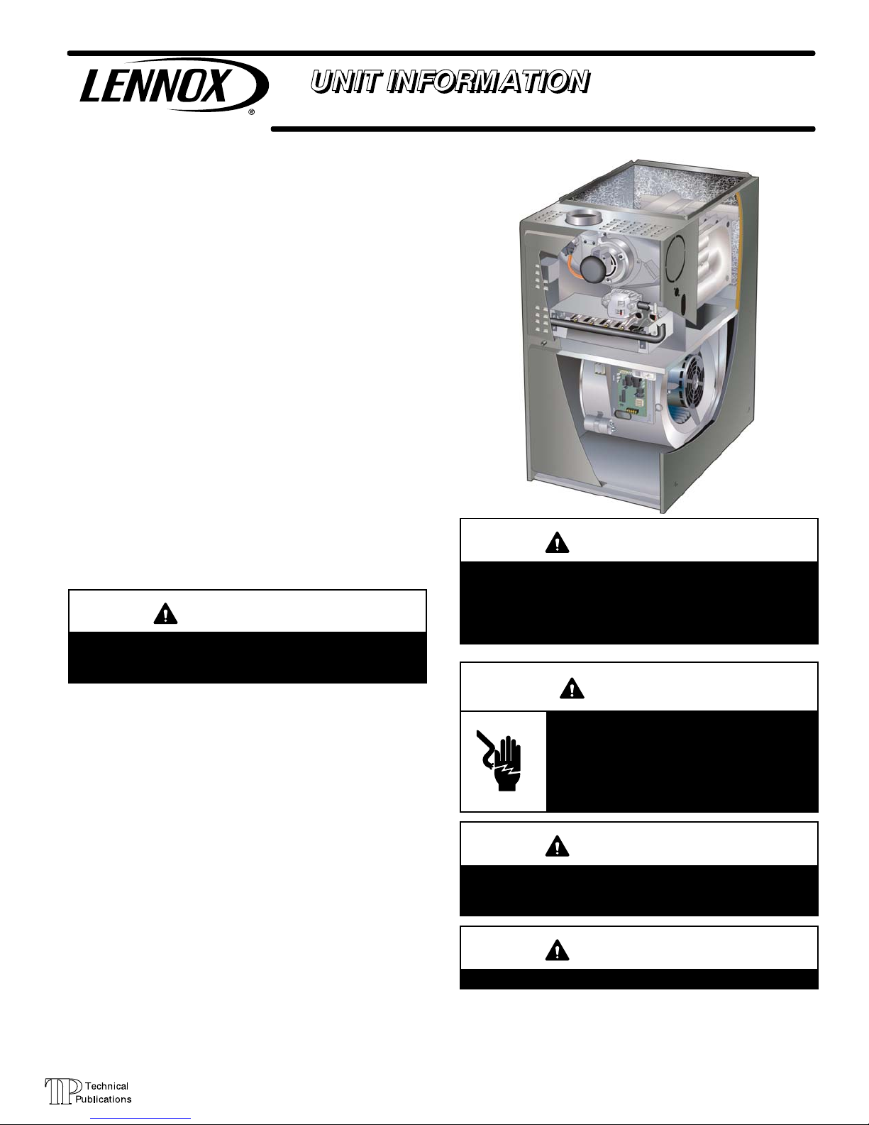
ML180UHA series units are mid-efficiency gas furnaces
used for upflow or horizontal applications only, manufac
tured with Lennox Duralok Plust heat exchangers formed
of aluminized steel. ML180UHA units are available in heat
ing capacities of 69.6 to 139.3 MJ/h and cooling applica
tions 10 to 17 kW. Refer to Engineering Handbook for prop
er sizing.
Units are factory equipped for use with natural gas. Kits are
available for conversion to LP/Propane operation.
ML180UHA model units are equipped with a hot surface
ignition system. All units use a redundant gas valve to as
sure safety shut-off as required.
All specifications in this manual are subject to change. Pro
cedures outlined in this manual are presented as a recom
mendation only and do not supersede or replace local or
state codes. In the absence of local or state codes, the
guidelines and procedures outlined in this manual (except
where noted) are recommended only and do not constitute
code.
Revised 05 /2017
WARNING
This product contains a chemical known to the State
of California to cause cancer, birth defects, or other
reproductive harm.
TABLE OF CONTENTS
Specifications Page 2.............................
Blower Data Page 3..............................
Parts Identification Page 5.........................
I Unit Components Page 6........................
ML180UHA
IMPORTANT
Improper installation, adjustment, alteration, service
or maintenance can cause property damage, person
al injury or loss of life. Installation and service must
be performed by a qualified installer, service agency
or the gas supplier.
WARNING
Electric shock hazard. Can cause injury
or death. Before attempting to perform
any service or maintenance, turn the
electrical power to unit OFF at discon
nect switch(es). Unit may have multiple
power supplies.
II Installation Page 14.............................
III Start Up Page 14..............................
IV Heating System Service Checks Page 15.........
V Typical Operating Characteristics Page 19.........
VI Maintenance Page 20..........................
VII Wiring and Sequence of Operation Page 22......
Page 1
WARNING
Sharp edges.
Be careful when servicing unit to avoid sharp edges
which may result in personal injury.
WARNING
Do not modify this appliance.
© 2017 Lennox Industries Inc.
Page 2
Page 2
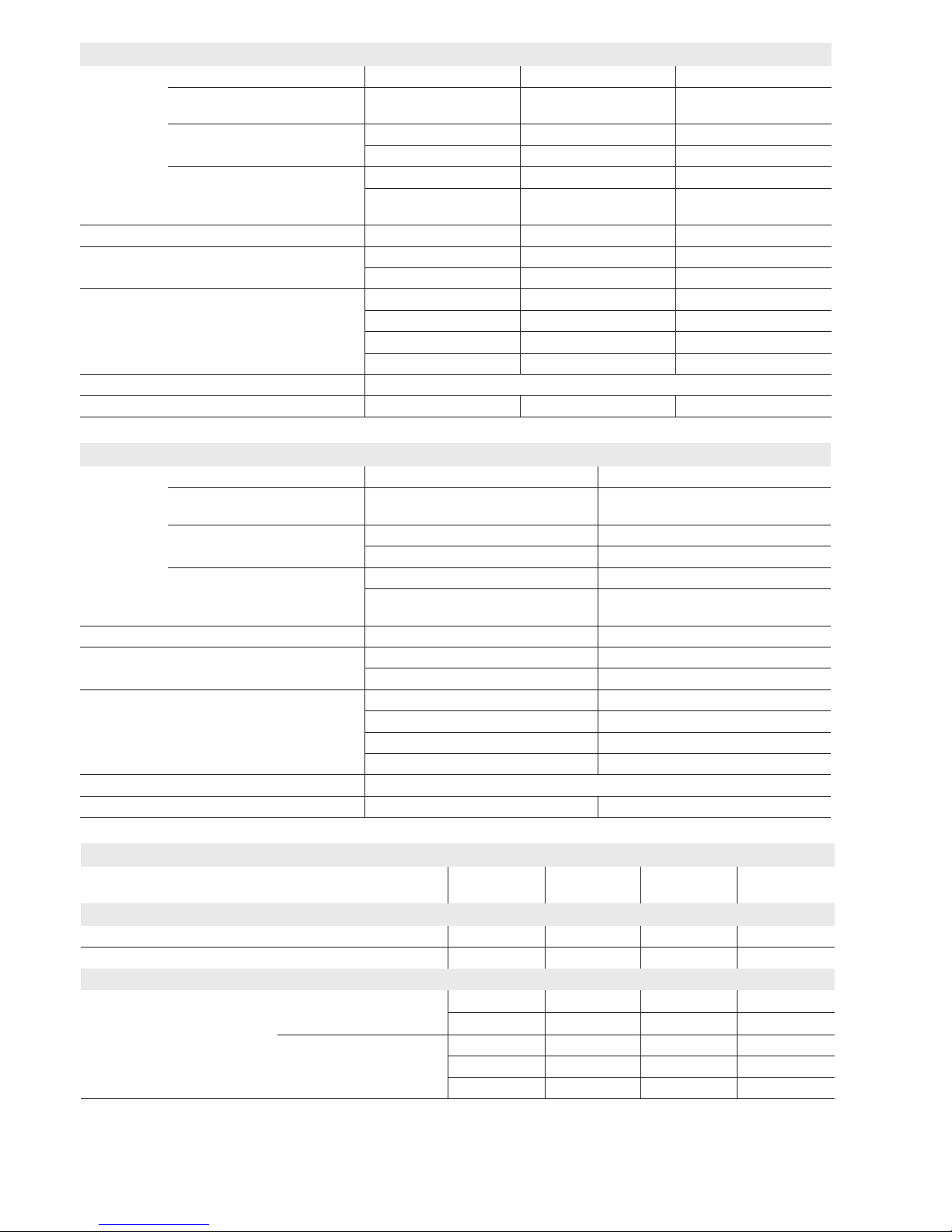
SPECIFICATIONS
Gas
Heating
Performance
Model Number ML180UH070AP36A ML180UH090AP48B ML180UH110AP36C
Australian Gas Association
Energy Rating - Stars
3.8 3.7 3.8
Input - Mj/h 69.6 92.8 116.1
Output - kW 15.5 20.6 25.8
Temperature rise range - °C 14 - 31 14 - 31 19 - 36
Gas Manifold Pressure (kPa)
Natural Gas / Propane
0.87 / 2.30 0.87 / 2.30 0.87 / 2.30
High Static - Pa 125 125 125
Connections Flue connection - mm round 102 102 102
Gas pipe size IPS 1/2 in. 1/2 in. 1/2 in.
Indoor
Blower
Wheel nom. diameter x width - mm 254 x 203 254 x 254 254 x 254
Motor output - W 248 373 373
Add-on cooling - kW 7-10.6 7-14.1 7-14.1
Air Volume Range - L/s 282 - 716 229 - 890 239 - 827
Electrical Data Voltage 220/240 volts - 50 hertz - 1 phase (less than 10 amps)
Shipping Data kg - 1 package 54 63 70
NOTE - Filters and provisions for mounting are not furnished and must be eld provided.
SPECIFICATIONS
Gas
Heating
Performance
Model Number ML180UH110AP60C ML180UH135AP60D
Australian Gas Association
Energy Rating - Stars
3.8 3.9
Input - Mj/h 116.1 139.3
Output - kW 25.8 31.0
Temperature rise range - °C 17 - 33 17 - 33
Gas Manifold Pressure (kPa)
Natural Gas / Propane
0.87 / 2.30 0.87 / 2.30
High Static - Pa 125 125
Connections Flue connection - mm round 102 102
Gas pipe size IPS 1/2 in. 1/2 in.
Indoor
Blower
Wheel nom. diameter x width - mm 292 x 254 279 x 279
Motor output - W 746 746
Add-on cooling - kW 14.1-17.6 14.1-17.6
Air Volume Range - L/s 633 - 1138 602 - 1159
Electrical Data Voltage 220/240 volts - 50 hertz - 1 phase (less than 10 amps)
Shipping Data kg - 1 package 71 79
NOTE - Filters and provisions for mounting are not furnished and must be eld provided.
OPTIONAL ACCESSORIES - ORDER SEPARATELY
“A” Width
Models
“B” Width
Models
“C” Width
Models
“D” Width
Models
CABINET ACCESSORIES
Horizontal Suspension Kit - Horizontal only 51W10 51W10 51W10 51W10
Return Air Base - Upow only 65W75 50W98 50W99 51W00
FILTERS
1
Air Filter and Rack Kit Horizontal (end) 87L95 87L96 87L97 87L98
Size of lter - mm 356 x 635 x 25 457 x 635 x 25 508 x 635 x 25 635 x 635 x 25
Side Return Single 44J22 44J22 44J22 44J22
Ten Pack 66K63 66K63 66K63 66K63
Size of lter - mm 406 x 635 x 25 406 x 635 x 25 406 x 635 x 25 406 x 635 x 25
1
Cleanable polyurethane, frame-type lter.
Page 3
Page 3
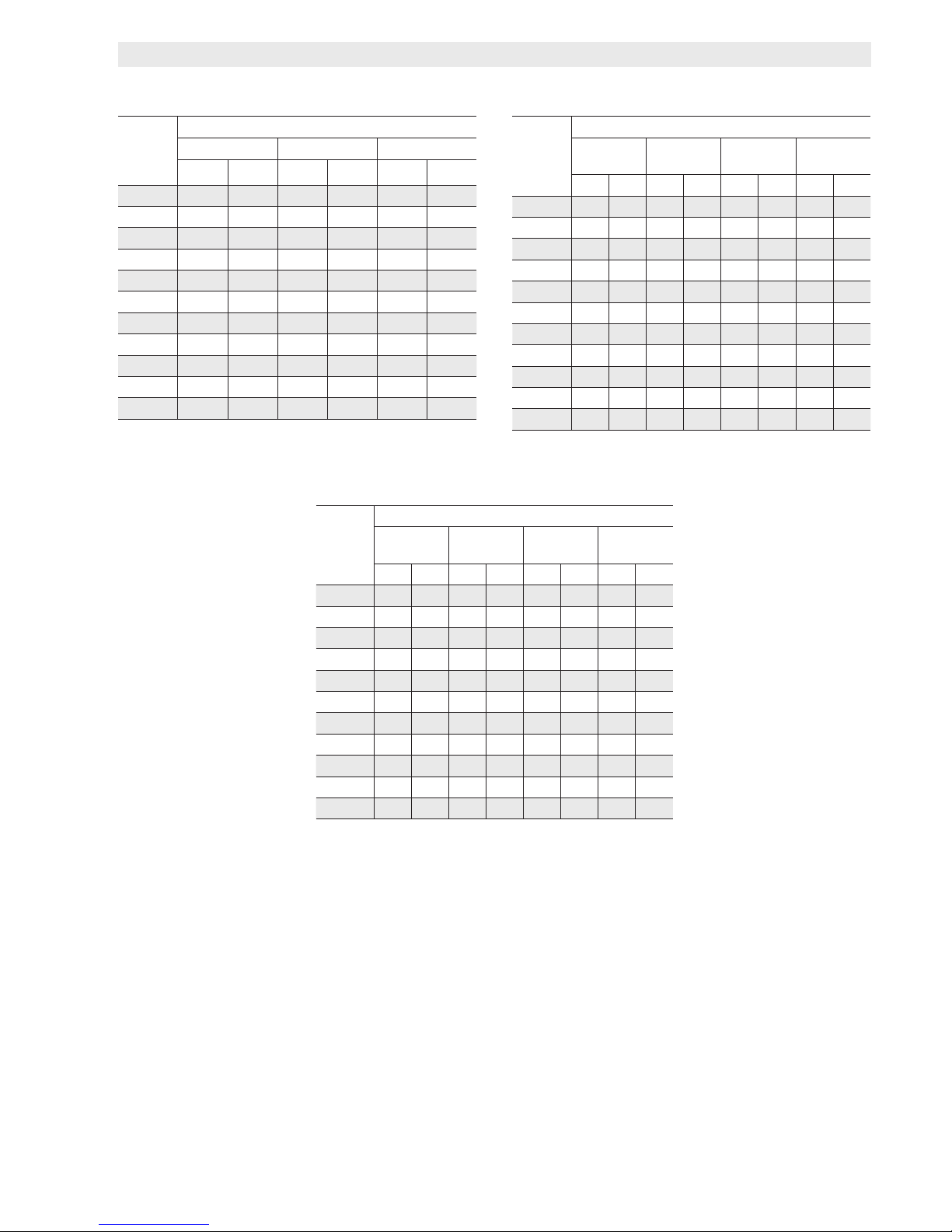
BLOWER DATA
ML180UH070AP36A PERFORMANCE (Less Filter)
External
Static
Pressure
Pa
Air Volume at Various Blower Speeds
High Medium Low
L/s Watts L/s Watts L/s Watts
0 716 771 589 615 469 468
25 687 752 564 597 435 448
50 675 724 554 583 430 441
75 662 708 547 569 421 430
100 649 691 530 554 408 417
125 633 672 517 541 393 405
150 616 650 503 524 372 387
175 595 624 488 514 359 375
200 573 608 472 494 324 363
225 551 590 447 477 307 346
250 523 561 424 454 282 331
ML180UH090AP48B PERFORMANCE (Less Filter)
External
Static
Pressure
Pa
Air Volume at Various Blower Speeds
High
Medium-
High
Medium-
Low
Low
L/s Watts L/s Watts L/s Watts L/s Watts
0 890 1085 715 892 497 598 423 493
25 849 1050 679 855 463 577 386 481
50 849 1016 679 831 460 565 384 464
75 831 967 676 807 456 546 369 447
100 827 937 667 773 452 526 364 434
125 816 906 660 747 439 509 349 421
150 799 872 647 718 426 494 331 408
175 784 845 629 691 411 477 308 394
200 754 808 601 642 394 460 290 383
225 722 765 577 622 359 435 256 363
250 674 713 555 593 332 421 229 348
ML180UH110AP36C PERFORMANCE (Less Filter)
External
Static
Pressure
Pa
Air Volume at Various Blower Speeds
High
Medium-
High
Medium-
Low
Low
L/s Watts L/s Watts L/s Watts L/s Watts
0 827 1106 660 884 460 574 404 478
25 800 1063 630 850 434 558 378 463
50 801 1043 631 819 432 541 369 451
75 779 984 631 807 434 527 359 438
100 773 962 624 777 422 512 352 422
125 773 938 620 758 408 490 335 4 11
150 761 907 609 725 382 472 331 396
175 741 854 593 695 383 460 319 386
200 722 832 580 659 366 441 299 372
225 699 777 554 638 351 432 263 354
250 677 741 527 600 331 4 11 239 340
Page 4
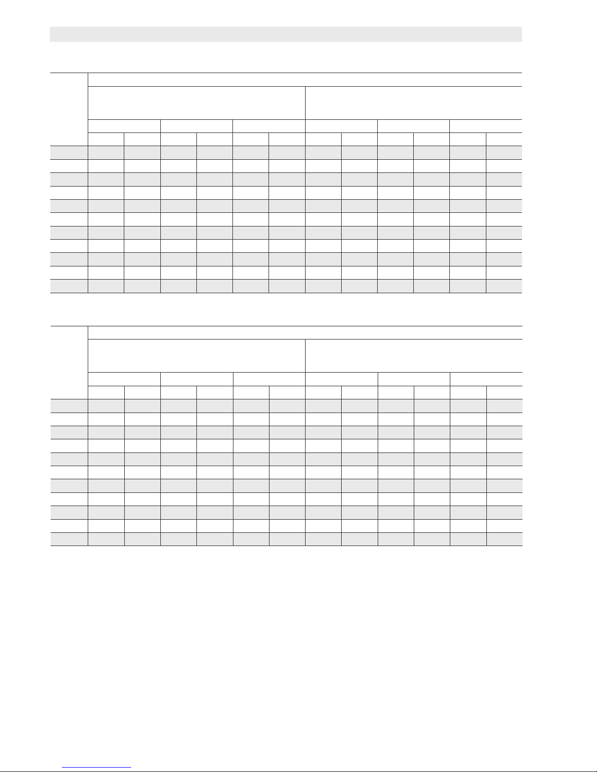
ML180UH110AP60C PERFORMANCE (Less Filter)
External
Static
Pressure
Pa
Air Volume at Different Blower Speeds
Bottom Return Air, Side Return Air with Optional
Return Air Base, Return Air from Both Sides or Return
Air from Bottom and One Side.
Single Side Return Air − Air volumes in bold require eld
fabricated transition to accommodate 508 x 635 x 25 mm
air lter in order to maintain proper air velocity.
High Medium Low High Medium Low
L/s Watts L/s Watts L/s Watts L/s Watts L/s Watts L/s Watts
0 1165 1447 964 1173 826 987 1126 1452 934 1172 794 984
25 1144 1408 938 1149 803 966 1104 1427 910 1150 772 964
50 1115 1389 932 1121 797 943 1085 1391 902 1126 768 943
75 1104 1358 922 1104 787 926 1071 1356 896 1110 756 925
100 1084 1333 908 1082 773 902 1059 1340 881 1079 750 907
125 1063 1303 905 1079 756 877 1037 1310 869 1064 741 890
150 1043 1274 888 1050 748 865 1020 1282 860 1041 731 872
175 1027 1249 871 1024 738 845
1005 1248 839 1022 717 852
200 1005 1224 849 994 723 815 987 1224 821 997 699 831
225 980 1179 835 974 696 800 956 1192 801 966 678 808
250 947 1140 807 943 677 775 939 1158 789 955 665 786
ML180UH135AP60D PERFORMANCE (Less Filter)
External
Static
Pressure
Pa
Air Volume at Different Blower Speeds
Bottom Return Air, Side Return Air with Optional
Return Air Base, Return Air from Both Sides or Return
Air from Bottom and One Side.
Single Side Return Air − Air volumes in bold require eld
fabricated transition to accommodate 508 x 635 x 25 mm
air lter in order to maintain proper air velocity.
High Medium Low High Medium Low
L/s Watts L/s Watts L/s Watts L/s Watts L/s Watts L/s Watts
0 1153 1460 958 1167 810 967 1114 1469 941 1219 786 992
25 1126 1425 931 1139 788 945 1091 1440 917 1196 759 967
50 1118 1411 923 1125 773 928 1079 1411 913 1173 751 950
75 1087 1374 915 1113 765 914 1064 1402 893 1149 743 933
100 1083 1344 891 1079 752 900 1048 1375 887 1130 734 920
125 1067 1325 890 1066 741 884 1032 1345 866 1101 720 899
150 1038 1284 862 1036 731 869 1012 1322 852 1072 708 881
175 1034 1269 844 1016 712 849
994 1291 834 1053 690 860
200 1005 1239 832 995 697 824 987 1271 820 1029 663 834
225 977 1204 804 975 677 813 956 1238 797 1010 650 815
250 952 1173 789 953 640 781 936 1220 783 988 627 795
BLOWER DATA
Page 5
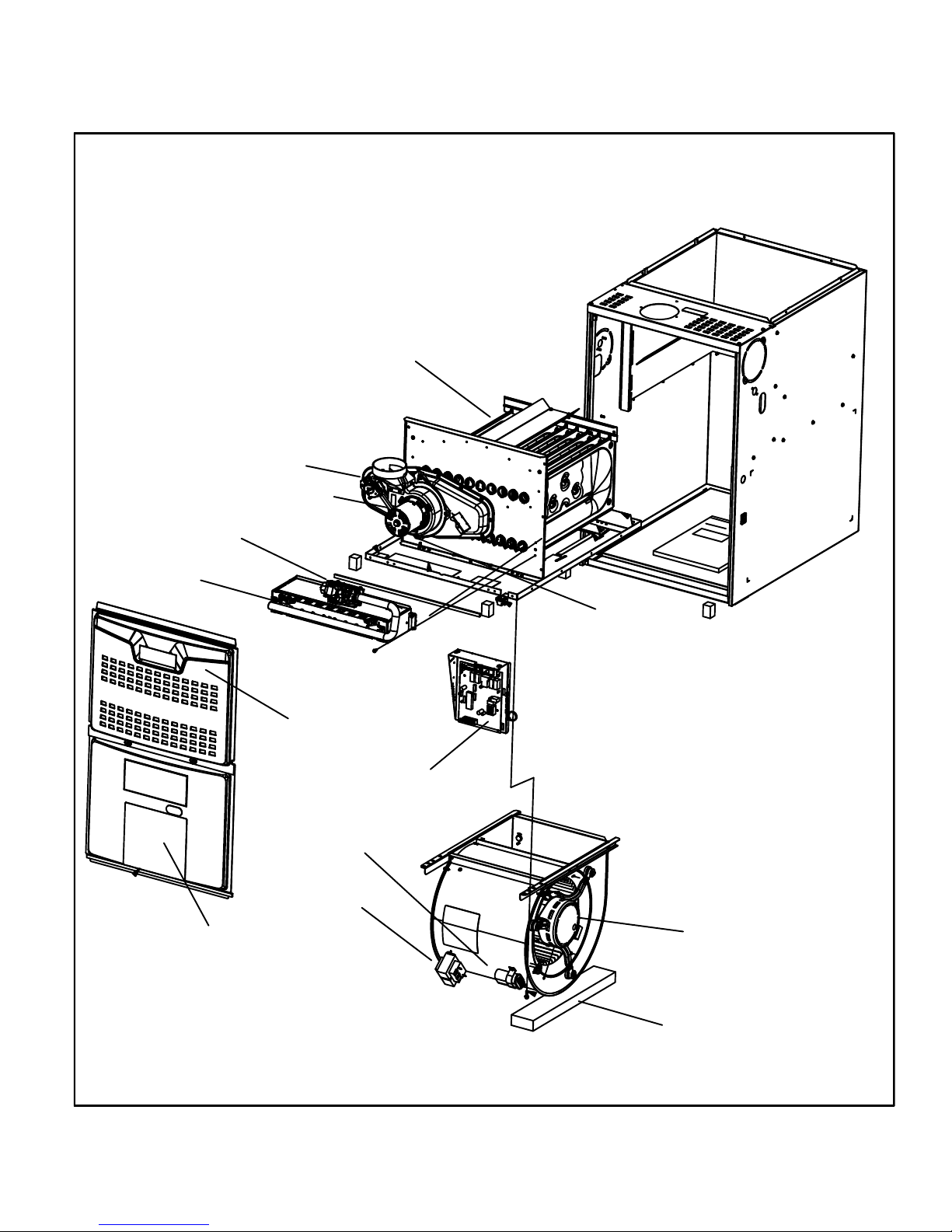
Pressure Switch
Combustion Air Inducer
Gas Valve
Burner/Manifold Assembly
ML180UHA PARTS ARRANGEMENT
Heat Exchanger
Blower Access Panel
Upper Access Panel
Control Box
Capacitor
Transformer
Limit Switch
IEC Receptacle
(under combustion air inducer)
Blower Assembly
Shipping Pad
ML180UH090AP48B, & ML180UH110AP36C only.
(
Remove prior to operation
)
FIGURE 1
Page 5
Page 6
I-UNIT COMPONENTS
ML180UHA unit components are shown in figure 1.The
gas valve, combustion air inducer and burners can be ac
cessed by removing the upper access panel. Electrical
components are in the control box (figure 2) found in the
blower section.
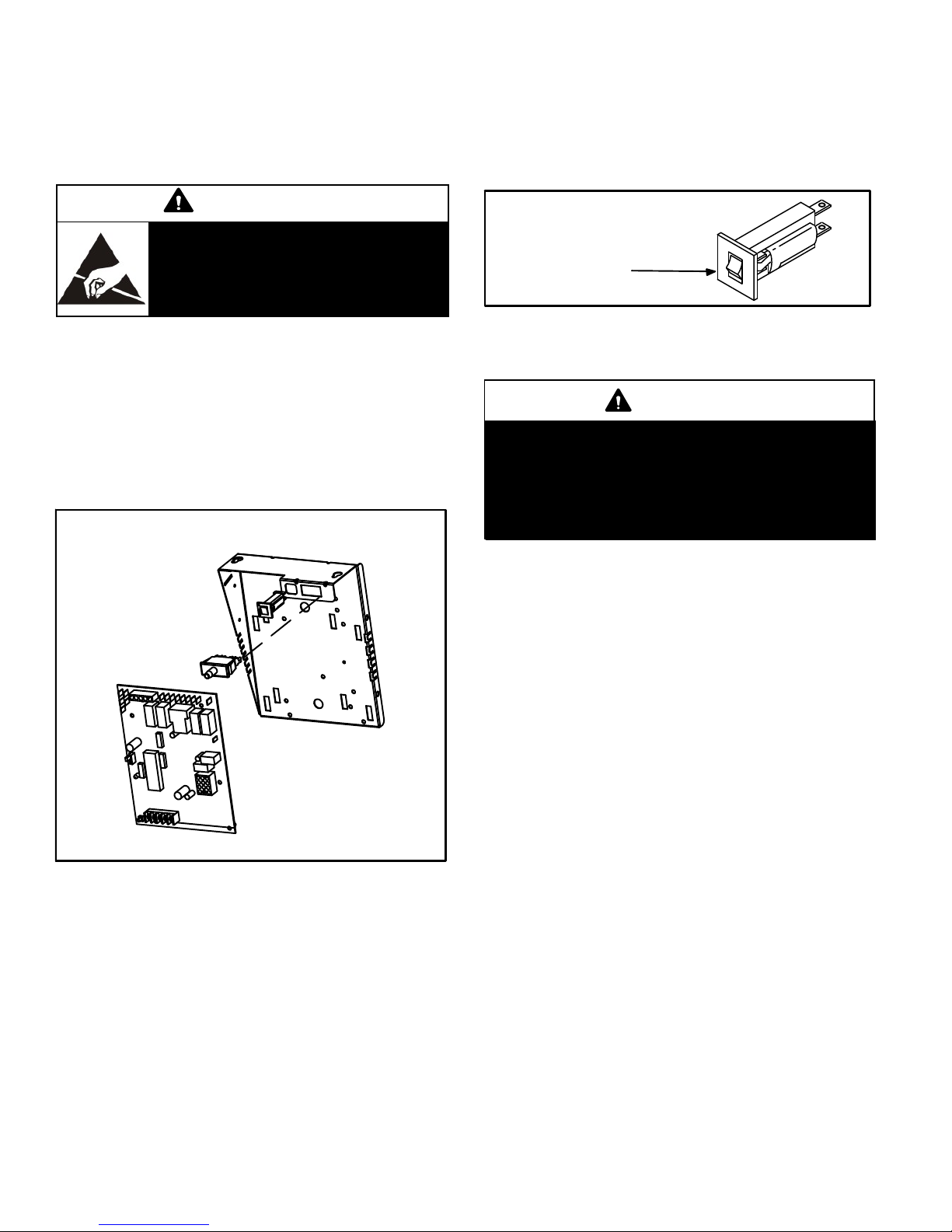
3. Circuit Breaker (CB8)
A 24V circuit breaker is also located in the control box.
The switch provides overcurrent protection to the trans
former (T1). The breaker is rated 3A at 32V. If the current
exceeds this limit the breaker will trip and all unit opera
tion will shutdown. The breaker can be manually reset
by pressing the button on the face. See figure 3.
CAUTION
Electrostatic discharge can affect elec
tronic components. Take precautions
to neutralize electrostatic charge by
touching your hand and tools to metal
prior to handling the control.
1. Control Transformer (T1)
A transformer located in the control box provides power to
the low voltage section of the unit. Transformers on all
models are rated 40VA with a 230V primary and a 24V sec
ondary.
2. Door Interlock Switch (S51)
A door interlock switch rated 14A at 230VAC is wired in se
ries with line voltage. When the blower door is removed the
unit will shut down.
CONTROL BOX ML180UHA
Door Interlock Switch
Integrated Control
FIGURE 2
CIRCUIT BREAKER CB8
PRESS TO RESET
FIGURE 3
4. Integrated Control (A92)
WARNING
Shock hazard.
Disconnect power before servicing. Control is not
field repairable. If control is inoperable, simply re
place entire control.
Can cause injury or death. Unsafe operation will re
sult if repair is attempted.
The hot surface ignition control system consisting of an in
tegrated control (figure 4 with control terminal designa
tions in tables 1 and 2.) sensor and ignitor (figure 6). The
integrated control and ignitor work in combination to en
sure furnace ignition and ignitor durability. The integrated
control, controls all major furnace operations. The inte
grated control also features one LED light (AN1 red) for
troubleshooting and two accessory terminals rated at (1)
one amp. The integrated control also features a (3) amp
fuse for overcurrent protection. See table 3 for trouble
shooting diagnostic codes. The nitride ignitor is made
from a non-porous, high strength proprietary ceramic ma
terial that provides long life and trouble free maintenance.
The integrated control continuously monitors line voltage
and maintains the ignitor power at a consistent level to
provide proper lighting and maximum ignitor life.
Page 6
Page 7
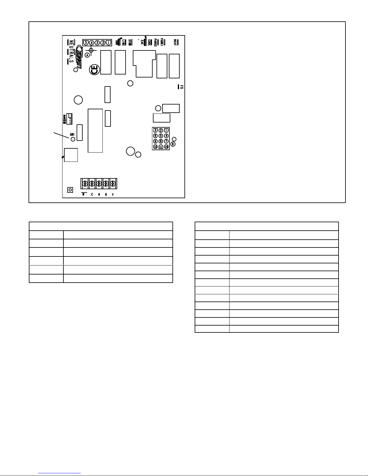
LED
(red)
INTEGRATED CONTROL
TERMINAL DESIGNATIONS
HUM - Humidifier 230VAC
LINE - Input 230VAC
XFMR - Transformer 230VAC
EAC - Electronic Air Cleaner 230VAC
COOL - Cool Speed 230VAC
PARK1, PARK2 - Dead terminals for alternate speed taps
NEUTRALS - Neutral terminals 230VAC
HEAT - Heating Speed 230VAC
FS - Flame Sense
TABLE 1
5-Pin Terminal Designation
PIN # FUNCTION
1 Ignitor Line
2
3
4
5
Not Used
Combustion Air Inducer Low
Combustion Air Inducer Neutral
Ignitor Neutral
FIGURE 4
TABLE 2
12-Pin Terminal Designations
PIN # FUNCTION
1 Not Used
2 Not Used
3 Rollout Switch Input
4 Ground
5 TH 24V Hot
6 High Limit Input
7 Gas Valve Line
8 Gas Valve Common
9 TR 24V Return
10 Ground
11 Rollout Switch Output
12 Pressure Switch
Page 7
Page 8
TABLE 3
FLASH CODE
(X + Y)
STATUS / ERROR DESCRIPTION
FLASH CODE DESCRIPTIONS
Pulse A 1/4 second flash followed by four seconds of off time.
Heartbeat Constant 1/2 second bright and 1/2 second dim cycles.
X + Y
Pulse Power on - Standby.
Heartbeat Normal operation - signaled when heating demand initiated at thermostat.
LED flashes X times at 2Hz, remains off for two seconds, flashes Y times at 2Hz, remains off for four
seconds, then repeats.
FLAME CODES
1 + 2 Low flame current -- check flame sensor.
1 + 3 Flame sensed out of sequence -- flame still present. Flame sensed without gas valve energized.
PRESSURE SWITCH CODES
2 + 3 Low pressure switch failed open. Check blocked inlet/exhaust .
2 + 4 Low pressure switch failed closed. Pressure switch closed prior to activation of combusiton air inducer.
LIMIT CODE
3 + 1 Limit switch open.
WATCHGUARD CODES
4 + 1 Watchguard -- Exceeded maximum number of retries. Burners failed to light.
4 + 2 Watchguard -- Exceeded maximum number of retries or last retry was due to pressure switch opening.
4 + 3 Watchguard -- Exceeded maximum number of retries or last retry was due to flame failure.
4 + 5 Watchguard -- Limit remained open longer than three minutes.
4 + 6 Watchguard -- Flame sensed out of sequence; flame signal gone.
4 + 8 Low line voltage.
HARD LOCKOUT CODES
5 + 1 Hard lockout -- Rollout circuit open or previously opened.
5 + 4
5 + 5 Gas valve fault ( sensed open when should be closed, or sensed closed when should be open).
5 + 6 Program memory fault (internal microprocessor memory fault)
5 + 7 Flame sense circuit fault. (flame sense circuit or bad flame probe fault).
5 + 8 No communication packet fault (loss of communications between redundant microprocessor fault).
5 + 9 Bad communication packet fault. (corrupted communications between redundant microprocessor fault).
5 + 10 Redundant variable fault. (internal microprocessor memory retention fault).
Reversed line voltage polarity (control will restart if the error recovers). And or no Earth groas valve
faulund
Page 8
Page 9
Electronic Ignition
On a call for heat the integrated control monitors the com
bustion air inducer pressure switch. The control board will
not begin the heating cycle if the pressure switch is closed
(by-passed). Once the pressure switch is determined to be
open, the combustion air inducer is energized. When the
differential in the pressure switch is great enough, the pres
sure switch closes and a 15-second pre-purge begins. If
the pressure switch is not proven within 2-1/2 minutes, the
integrated control goes into Watchguard-Pressure Switch
mode for a 5-minute re-set period.
After the 15-second pre-purge period, the ignitor warms up
for 20 seconds during which the gas valve opens at 19 sec
onds for a 4-second trial for ignition. The ignitor remains
energized for the first 3 seconds during the 4 second trial. If
ignition is not proved during the 4-second period, the inte
grated control will try four more times with an inter purge
and warm-up time between trials of 35 seconds. After a to
tal of five trials for ignition (including the initial trial), the inte
grated control goes into Watchguard-Flame Failure mode.
After a 60-minute reset period, the integrated control will
begin the ignition sequence again.
The integrated control has an added feature of ignitor pow
er regulation to maintain consistent lighting and longer igni
tor life under all line voltage conditions.
Fan Time Control
Heating Fan On Time
The fan on time of 30 seconds is not adjustable.
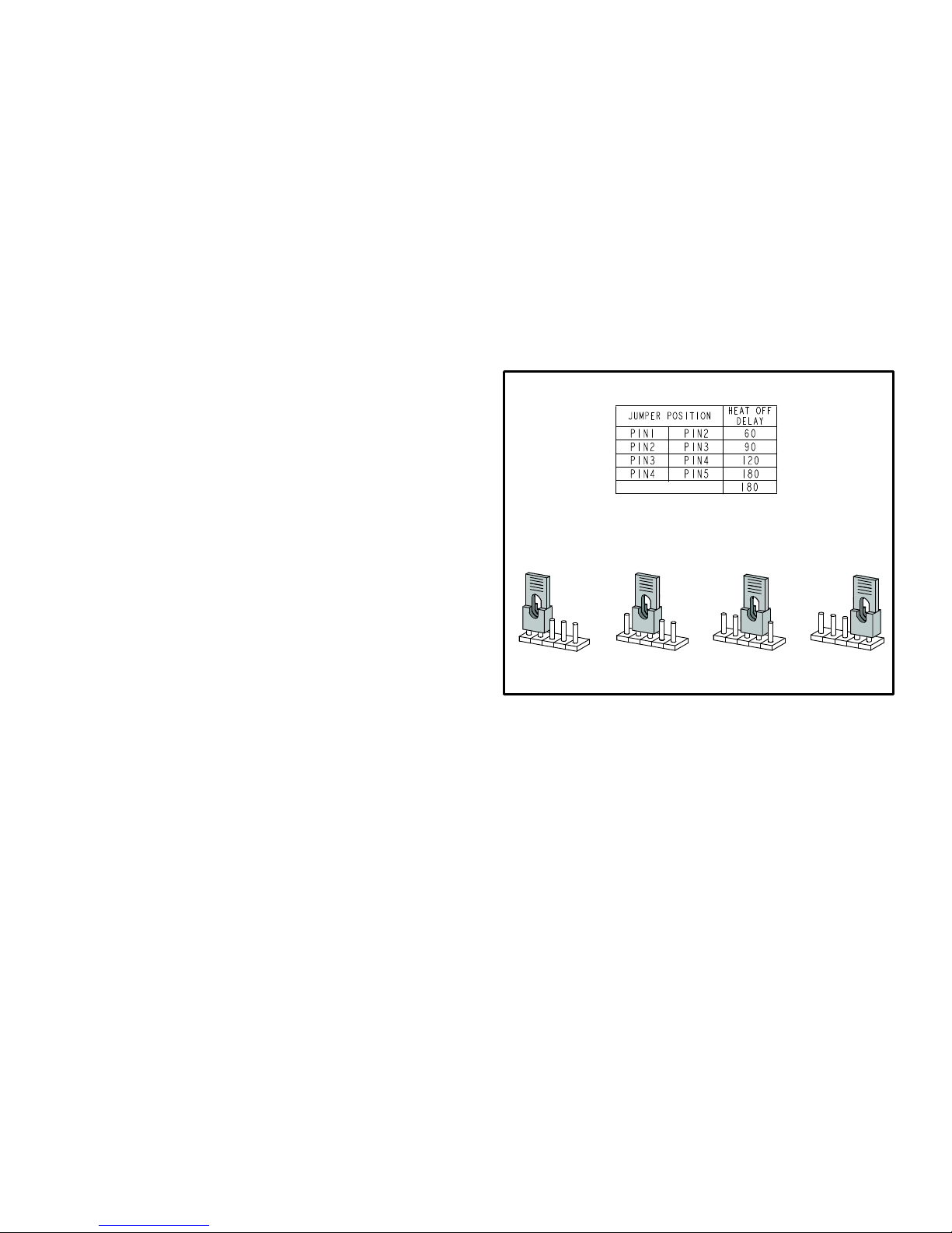
Heating Fan Off Time
Fan off time (time that the blower operates after the heat
demand has been satisfied) can be adjusted by moving the
jumper to a different setting. The unit is shipped with a fac
tory fan off setting of 60 seconds. For customized comfort,
monitor the supply air temperature once the heat demand
is satisfied. Note the supply air temperature at the instant
the blower is de-energized.
Adjust the fan-off delay to achieve a supply air temperature
between 32° C - 43° C (90° F - 110° F) at the instant the
blower is de-energized. (Longer delay times allow for lower
air temperature, shorter delay times allow for higher air
temperature). See figure 5.
Cooling Fan On Time
The fan on time is 2 seconds and is not adjustable.
Cooling Fan Off Time
The control has a 45 second fan off delay after cooling de
mand has been met. This delay is factory set and not ad
justable.
HEAT FAN‐OFF TIME IN SECONDS
NO JUMPER
To adjust fan-off timing, reposition jumper across pins to
60 Second
off Time
60
90
120
180
achieve desired setting.
90 Second
off Time
60
90
120
180
120 Second
off Time
60
90
120
180
180 Second
off Time
60
90
120
180
FIGURE 5
Page 9
Page 10

Rollout Switches
ML180UHA HEATING COMPONENTS
Flue Transition
Ignitor
Gasket
Pressure Switch
Sensor
Manifold And Gas Valve
FIGURE 6
5. Flame Sensor (Figure 6)
A flame sensor is located on the left side of the burner sup
port. The sensor is mounted on the flame rollout plate and
the tip protrudes into the flame envelope of the left-most
burner. The sensor can be removed for service without re
moving any part of the burners. During operation, flame is
sensed by current passed through the flame and sensing
electrode. The integrated control allows the gas valve to re
main open as long as flame signal is sensed.
6. Flame Rollout Switches (Figure 6) (S47)
Flame rollout switch is a high temperature limit. Each fur
nace is equipped with two identical switches. The limit is a
N.C. SPST manual‐reset limit connected in series with the
integrated control A92. When S47 senses rollout, the inte
grated control immediately stops ignition and closes the
gas valve. If unit is running and flame rollout is detected, the
gas valve will close and integrated control will be disabled.
Rollout can be caused by a blocked heat exchanger, flue or
lack of combustion air. The switch has a factory setpoint of
99°C (210°F) and cannot be adjusted. To manually reset a
tripped switch, push the reset button located on the control.
Orifice Plate
Combustion Air Inducer
Collector Box
7. Primary Limit Control (S10)
The primary limit on ML180UHA units is located in the heating
vestibule panel under the combustion air inducer. See figure 1.
When excess heat is sensed in the heat exchanger, the limit
will open. If the limit is open, the integrated control energizes
the supply air blower and closes the gas valve. The limit auto
matically resets when unit temperature returns to normal. The
switch must reset within three minutes or SureLight
will go into Watchguard for one hour. The switch is factory
set and cannot be adjusted. The switch may have a different
setpoint for each unit model number. If limit switch must be
replaced, refer to Lennox ProductZone repair parts list on
Lennox DaveNet®.
®
control
Page 10
Page 11

8. Ignitor (Figure 6)
The nitride ignitor used on ML180UHA units is made from a
proprietary ceramic material. Ignitor longevity is enhanced
by controlling the voltage to the ignitor. To check ignitor,
measure its resistance and voltage. A value of 300 to 1300
ohms indicates a good ignitor. Voltage to the ignitor should
be 150VAC.
See figure 7 for resistance, and voltage check.
Voltmeter
(set to ohms)
Test 2
Test 1
NOTE - The ML180UHA furnace contains electronic
components that are polarity sensitive. Make sure that
the furnace is wired correctly and is properly grounded.
Test 1 - Remove 5-pin plug
from control. Insert test pins
from meter into plug pin 1 and
5. If reading is correct test is
over. If reading is outside ac
ceptable range move to test 2.
Test 2 - Separate the 2-pin jackplug and again check resistance to
the ignitor. If reading is acceptable
then the problem is the wiring be
tween the jackplug and integrated
control. If reading is acceptable re
place the ignitor.
Voltmeter
(set to AC)
Test - Do not separate 5 pin
jack-plug. Use a true RMS me
ter and carefully insert test pins
in plug pins 1 and 5. Measure
voltage.
FIGURE 7
Page 11
Page 12

9. Gas Valve (Figure 6)
The ML180UHA uses internally redundant gas valve to as
sure safety shut-off. If the gas valve must be replaced, the
same type valve must be used.
24VAC terminals and valve switch are located on the valve. All
terminals on the gas valve are connected to wires from the in
tegrated control. 24V applied to the terminals energizes the
valve.
Inlet and outlet pressure taps are located on the valve. A regu
lator adjustment screw is located on the valve.
LPG changeover kits are available from Lennox. Kits include
burner orifices and a gas valve regulator spring.
10. Combustion Air Inducer (B6)
All ML180UHA units use a combustion air inducer to move
air through the burners and heat exchanger during heating
operation. The blower uses a 230VAC motor. The motor
operates during all heating operation and is controlled by
integrated control A92. The inducer also operates for 15
seconds before burner ignition (pre‐purge) and for 5 sec
onds after the gas valve closes (post‐purge).
A pressure switch connected to the combustion air inducer
orifice plate is used to prove inducer operation. The combus
tion air inducer orifice will be different for each model. See
table 4 for orifice sizes. The switch monitors air pressure in
the inducer housing. During normal operation, the pressure in
the housing is negative. If pressure becomes less negative
(signifying any obstruction in the flue) the pressure switch
opens. When the proving switch opens, the integrated con
trol (A92) immediately de-energizes the gas valve to prevent
burner operation.
TABLE 4
ML180UHA Unit
C.A.I. Orifice Size mm (in)
11. Combustion Air Inducer
Pressure Switch (S18)
ML180UHA series units are equipped with a combustion air
pressure switch located on the combustion air inducer ori
fice bracket. The switch is connected to the combustion air
inducer housing by means of a flexible silicone hose. It mon
itors negative air pressure in the combustion air inducer
housing.
The switch is a single‐pole single‐throw proving switch elec
trically connected to the furnace control. The purpose of the
switch is to prevent burner operation if the combustion air in
ducer is not operating or if the flue becomes obstructed.
On start‐up, the switch senses that the combustion air in
ducer is operating. It closes a circuit to the integrated con
trol when pressure inside the combustion air inducer de
creases to a certain set point. Set points vary depending on
unit size. See table 5. The pressure sensed by the switch is
negative relative to atmospheric pressure. If the flue be
comes obstructed during operation, the switch senses a
loss of negative pressure (pressure becomes more equal
with atmospheric pressure) and opens the circuit to the in
tegrated control and gas valve. A bleed port on the switch
allows relatively dry air in the vestibule to purge switch tub
ing, to prevent condensate build up.
TABLE 5
ML180UHA Set Point Pa (in)
070AP36A 150 (.60)
090AP48B 150 (.60)
110AP36C, 110AP60C 150 (.60)
135AP60D 150 (.60)
070AP36A 35.7 (1.406)
090AP48B 42.2 (1.660)
110A36C, 110AP60C 47.6 (1.875)
135AP60D 55.6 (2.188)
The switch is factory set and is not field adjustable. It is
a safety shut‐down control in the furnace and must not
be by-passed for any reason. If switch is closed or bypassed, the integrated control will not initiate ignition
at start up.
Page 12
Page 13

Multiple Venting
The ML180UHA furnace can vent in multiple positions. See
figure 8.
The make up box may be removed and the combustion air
inducer may be rotated clockwise or counterclockwise 90°
to allow for vertical or horizontal vent discharge in a vertical
or horizontal cabinet position. Remove the four mounting
Vent Pipe
Pressure
Switch
vent pipe
Collector Box
screws, rotate the assembly (assembly consists of orifice
plate, proving switch, gasket and combustion air inducer),
then reinstall the mounting screws. See unit Installation In
structions for more detail.
IMPORTANT
The combustion air pressure switch must be moved
for horizontal discharge air left position.
vent pipe
flue
vent pipe
transition
vent pipe
AIR
FLOW
Collector Box
FLOW
AIR
vent pipe
flue transition
AIR
FLOW
pressure switch
vent pipe
In all positions route the wires away from moving parts and the heat of the inducer
motor to prevent damage to the wires. The pressure switch must be installed above
the CAI to prevent moisture from collecting in the hoses or switch.
FIGURE 8
Page 13
Page 14

SUPPLY AIR BLOWER
AND SECONDARY LIMIT(S)
Left Side
ALIGN AND TIGHTEN SET SCREW WITH
FLAT SIDE OF MOTOR SHAFT
Right Side
SECONDARY
LIMIT (S)
MOTOR/BLOWER
ASSEMBLY
CAPACITOR
To Remove Blower From Unit: Disconnect Power, Remove
Control Box, Remove Bolts and Unplug Motor Wires From
Integrated Control. Then Slide Out Front of Unit.
FIGURE 9
12. Blower Motors and Capacitors
All ML180UHA units use direct drive blower motors. All mo
tors are 230V permanent split capacitor motors to ensure
maximum efficiency. Ratings for capacitors will be on motor
nameplate. If replacing the indoor blower motor or blower
wheel is necessary, placement is critical. The blower wheel
must be centered in the blower housing as shown in figure
10. When replacing the indoor blower motor the set screw
must be aligned and tightened with the motor shaft as
shown in figure 11.
Housing Hub
Set Screw
Motor
Shaft
NOTE - The 5 ton blower will have two flats
and two set screws 90° of each other .
FIGURE 11
13. Secondary Limit Controls
The secondary limit is located in the blower compartment in
the back side of the blower housing. See figure 9. When ex
cess heat is sensed in the blower compartment, the limit will
open. If the limit is open, the furnace control energizes the sup
ply air blower and closes the gas valve. The limit automatically
resets when unit temperature returns to normal. The secon
dary limit cannot be adjusted.
II- PLACEMENT AND INSTALLATION
Make sure unit is installed in accordance with installation
instructions and applicable codes.
III- START‐UP
A- Heating Start‐Up
BLOWER WHEEL REPLACEMENT
Center Blower Wheel
in Blower Housing
FIGURE 10
WARNING
Shock and burn hazard.
ML180UHA units are equipped with a hot surface
ignition system. Do not attempt to light manually.
Gas Valve Operation
MANIFOLD
PRESSURE
OUTLET
PORT
INLET
PRESSURE
PORT
White Rodgers 3600 Gas Valve
MANIFOLD
PRESSURE
ADJUSTMENT
SCREW
GAS VALVE SHOWN IN OFF POSITION
FIGURE 12
Page 14
Page 15

1 - STOP! Read the safety information at the beginning of
this section.
2 - Set the thermostat to the lowest setting.
3 - Turn off all electrical power to the unit.
4 - This furnace is equipped with an ignition device which
automatically lights the burners. Do not try to light the
burners by hand.
5 - Remove the upper access panel.
6 - Move gas valve lever to OFF position. Do not for c e .
See figure 12.
7 - Wait five minutes to clear out any gas. If you then smell
gas, STOP! Immediately call your gas supplier from a
neighbor's phone. Follow the gas supplier's instruc
tions. If you do not smell gas go to next step.
8 - Move gas valve lever to ON position. Do not force.
See figure 12.
9 - Replace the upper access panel.
10- Turn on all electrical power to to the unit.
11- Set the thermostat to desired setting.
NOTE - When unit is initially started, steps 1 through 11
may need to be repeated to purge air from gas line.
12- If the appliance will not operate, follow the instructions
“Turning Off Gas to Unit” and call the gas supplier.
Turning Off Gas to Unit
1 - Set the thermostat to the lowest setting.
2 - Turn off all electrical power to the unit if service is to be
performed.
3 - Remove the upper access panel.
4 - Move gas valve lever to OFF position. Do not for c e .
See figure 12.
5 - Replace the upper access panel.
B- Safety or Emergency Shutdown
B- Gas Piping
Gas supply piping should not allow more than 125Pa (13
mm W.C.)drop in pressure between gas meter and unit.
Supply gas pipe must not be smaller than unit gas connec
tion.
Compounds used on gas piping threaded joints should be
resistant to action of liquefied petroleum gases.
C- Testing Gas Piping
CAUTION
If a flexible gas connector is required or allowed by
the authority that has jurisdiction, black iron pipe
shall be installed at the gas valve and extend outside
the furnace cabinet.
IMPORTANT
In case emergency shutdown is required, turn off
the main shut‐off valve and disconnect the main
power to unit. These controls should be properly
labeled by the installer.
WARNING
Do not exceed 68Nm (50 ft-lbs) torque when attach
ing the gas piping to the gas valve.
When pressure testing gas lines, the gas valve must be dis
connected and isolated. Gas valves can be damaged if
subjected to more than 3.48kPag (0.5psig) See figure 13. If
the pressure is equal to or less than 3.48kPag (0.5psig),
close the manual shut-off valve before pressure testing to
isolate furnace from gas supply.
GAS PIPING TEST PROCEDURE
MANUAL MAIN SHUT-OFF VALVE
WILL NOT HOLD TEST PRESSURE IN EXCESS
OF 3.48kPa (0.5 PSIG 355 mm W.C.)
Disconnect main power to unit. Close manual and main gas
valves.
C- Extended Period Shutdown
Turn off thermostat or set to “UNOCCUPIED” mode. Close
all gas valves (both internal and external to unit) to guaran
tee no gas leak into combustion chamber. Turn off power to
unit. All access panels and covers must be in place and se
cured.
IV-HEATING SYSTEM SERVICE CHECKS
A- Certification
All units are Australian Gas Installation Code (AS/
NZS5601) certified. Refer to the ML180UHA Installation In
struction.
CAP
GAS VALVE
FIELD PROVIDED
LINE PRESSURE TAP
FIGURE 13
When checking piping connections for gas leaks, use pre
ferred means. Kitchen detergents can cause harmful corro
sion on various metals used in gas piping. Use of a specialty
Gas Leak Detector is strongly recommended.
Do not use matches, candles, flame or any other source of
ignition to check for gas leaks.
Page 15
Page 16

D- Gas Pressure Adjustment
Gas Flow (Approximate)
TABLE 6
GAS METER CLOCKING CHART
Seconds for One Revolution
Unit
-045 80 160 200 400
-070 55 110 136 272
-090 41 82 102 204
-110 33 66 82 164
-135 27 54 68 136
Natural-1000 btu/cu ft LP-2500 btu/cu ft
Furnace should operate at least 5 minutes before check
ing gas flow. Determine time in seconds for two revolu
tions of gas through the meter. (Two revolutions assures a
more accurate time.) Divide by two and compare to time
in table 6 below. If manifold pressure matches table 8 and
rate is incorrect, check gas orifices for proper size and re
striction. Remove temporary gas meter if installed.
NOTE - To obtain accurate reading, shut off all other gas
appliances connected to meter.
Manifold Pressure Measurement
1 - Remove the threaded plug from the outlet side of the
gas valve and install a field-provided barbed fitting.
Connect to a test gauge to measure manifold pres
sure.
2 - Start unit and allow 5 minutes for unit to reach steady
state.
3 - While waiting for the unit to stabilize, observe the
flame. Flame should be stable and should not lift from
burner. Natural gas should burn blue.
Natural LP
1 cu ft
Dial
2 cu ft
Dial
1 cu ft
Dial
2 cu ft
DIAL
4 - After allowing unit to stabilize for 5 minutes, record
manifold pressure and compare to value given in table
8.
NOTE - Shut unit off and remove manometer as soon as an
accurate reading has been obtained. Take care to remove
barbed fitting and replace threaded plug. Re-fire unit and
check for gas leaks. Seal any leaks if found.
E- Proper Combustion
Furnace should operate a minimum 15 minutes with cor
rect manifold pressure and gas flow rate before checking
combustion. Take combustion sample beyond the flue out
let and compare to the tables below. The maximum carbon
monoxide reading should not exceed 100 ppm.
TABLE 7
ML180UHA
Unit
CO2%
For Nat
CO2%
For L.P.
-070
-090
-110
6.3 - 7.8 7.0 - 9.0
-135
F- High Altitude
The manifold pressure may require adjustment and com
bustion air pressure switch may need replacing to ensure
proper combustion at higher altitudes. Refer to table 8 for
manifold pressure and table 9 for pressure switch change
and gas conversion kits.
IMPORTANT
For safety, shut unit off and remove manometer as
soon as an accurate reading has been obtained.
Take care to replace pressure tap plug.
Manifold Pressure Settings at all Altitudes
Model
Input Size
All Models
Gas
Nat 0.87 0.72 0.67 0.62 0.87 1.13 3.23
LP/propane 2.30 2.30 2.19 2.12 2.30 2.75 3.23
0-610 m*
(0-2000 ft)
* See table 9 for proper high altitude gas conversion kit.
Pressure Switch and Gas Conversion Kits at all Altitudes
Model
Input Size
070
090 80W51 80W56
110 80W51 80W56
135 No Change 80W51
High Altitude Pressure Switch Kit
0-610 m
(0-2000 ft)
No Change
611-1219 m
(2001-4000 ft)
80W51 80W56
611-914 m*
(2001-3000 ft.)
1220-1981 m
(4001-6500 ft)
TABLE 8
915-1219 m*
(3001-4000 ft)
1220-1524 m*
(4001-5000 ft.)
1525-1981 m*
(5001-6500 ft)
TABLE 9
High Altitude
Natural Gas Burner
Orifice Kit
1525-1981 m
(5001-6500 ft)
73W37 11K15 97W04 96W95
Natural Gas to LP/Propane
Change Over Kit
0-1524 m
(0-5000 ft)
1525-1981 m
(5001-6500 ft)
Page 16
Line Pressure
kPa
Min Max
LP/Propane to
Natural Gas
Change Over Kit
1-1524 m
(1-5000 ft)
Page 17

G- Flame Signal
A microamp DC meter is needed to check the flame signal
on the integrated control.
Flame (microamp) signal is an electrical current which passes
from the integrated control to the sensor during unit operation.
Current passes from the sensor through the flame to ground to
complete a safety circuit.
To Measure Flame Signal - Integrated Control:
Use a digital readout meter capable of reading DC micro
amps. See figure 14 and table 10 for flame signal check.
1 - Set the meter to the DC amps scale.
2 - Turn off supply voltage to control.
Measuring Flame Signal
3 - Disconnect integrated control flame sensor wire from
the flame sensor.
4 - Connect (-) lead to flame sensor.
5 - Connect (+) lead to the ignition control sensor wire.
6 - Turn supply voltage on and close thermostat contacts to
cycle system.
7 - When main burners are in operation for two minutes, take
reading.
TABLE 10
Flame Signal in Microamps
Normal Low Drop Out
1.5 0.5 - 1.4 0.4
Flame
Sensor
Flame Sensor
Wire
Integrated
Control
(+)
Flame Sensor
Terminal
(+) To Control
Sensor
Terminal
Remove Sensor Wire from
Integrated Control and
Connect Alligator Clip (−)
to Frame Sensor Lead
DIGITAL METER
Set dial to measure dc microamps
Red Collar
Indicates
Positive Leads
(+)
(-) To
flame
sensor
Remove Sensor Wire from
Integrated Control and
Connect Alligator Clip (+)
to Terminal on Control
FIGURE 14
Page 17
Page 18

H- Proper Ground and Voltage
A poorly grounded furnace can contribute to premature ig
nitor failure. Use the following procedure to check for
ground and voltage to the integrated control.
1 - Measure the AC voltage between Line Neutral (spade
terminals) and “C” terminal (low voltage terminal
block) on the integrated control. See figure 15. A wide
variation in the voltage between Line Neutral and “C”
as a function of load indicates a poor or partial ground.
Compare the readings to the table below. If the read
ings exceed the maximum shown in table 11, make re
pairs before operating the furnace.
2 - In addition, measure the AC voltage from Line Hot to
Line Neutral (spade terminals) on the integrated con
trol. See figure 16. This voltage should be in the range
of 204 to 264VAC.
TABLE 11
Furnace Status
Power On Furnace Idle 0.3 2
CAI / Ignitor Energized 0.75 5
Indoor Blower Energized Less than 2 10
CHECK VOLTAGE BETWEEN LINE NEUTRAL
AND LOW VOLTAGE “C” TERMINAL
Measurement VAC
Expected Maximum
CHECK VOLTAGE BETWEEN LINE HOT
AND LINE NEUTRAL
AN2
AN1
GREEN
RED
AN1
RED
AN2
GREEN
FIGURE 16
FIGURE 15
Page 18
Page 19

V-TYPICAL OPERATING CHARACTERISTICS
A-Blower Operation and Adjustment
NOTE- The following is a generalized procedure and
does not apply to all thermostat controls.
1 - Blower operation is dependent on thermostat control
system.
2 - Generally, blower operation is set at thermostat sub
base fan switch. With fan switch in ON position, blower
operates continuously. With fan switch in AUTO position,
blower cycles with demand or runs continuously while
heating or cooling circuit cycles.
3 - Depending on the type of indoor thermostat, blower
and entire unit will be off when the system switch is in
OFF position.
B-Temperature Rise (Figure 17)
Temperature rise for ML180UHA units depends on unit in
put, blower speed, blower horsepower and static pressure
as marked on the unit rating plate. The blower speed must
be set for unit operation within the range of “TEMP. RISE
°C” listed on the unit rating plate.
C-External Static Pressure
1 - Tap locations shown in figure 18 .
2 - Punch a 6.3 mm (1/4”) diameter hole in supply and re
turn air plenums. Insert manometer hose flush with in
side edge of hole or insulation. Seal around the hose
with permagum. Connect the zero end of the manome
ter to the discharge (supply) side of the system. On
ducted systems, connect the other end of manometer
to the return duct as above.
3 - With only the blower motor running and the evaporator
coil dry, observe the manometer reading. Adjust blow
er motor speed to deliver the air desired according to
the job requirements. For heating speed external static
pressure drop must not be more than 125Pa (0.5”). For
cooling speed external static pressure drop must not
be more than 200Pa (0.8” W.C.)
4 - Seal the hole when the check is complete.
EXTERNAL STATIC PRESSURE
Supply Duct Static ________
Return Duct Static + _____
Total Duct Static =
________
(dry coil)
TEMPERATURE RISE
Supply Duct Temperature ________
Return Duct Temperature
Temperature Rise = ________
Supply Air
Return Air
FIGURE 17
_
_____
Supply Air
or
Return Air
FIGURE 18
-+
D-Blower Speed Taps
Blower speed tap changes are made on the integrated con
trol. See figure 4. The heating tap is connected to the
“HEAT” terminal and the cooling tap is connected to the
“COOL” terminal. On all units the continuous blower tap is
the same as the heating tap and unused taps must be se
cured on two dummy terminals labeled ”PARK. To change
out existing speed tap, turn off power and switch out speed
tap with tap connected to “PARK”. See blower speed tap
table on unit diagram for motor tap colors for each speed.
Page 19
Page 20

VI-MAINTENANCE
A-Preliminary and Seasonal Checks
1 - Inspect electrical wiring, both field and factory installed
for loose connections. Tighten as required.
2 - Check voltage at disconnect switch. Voltage must be
within range listed on the nameplate. If not, consult the
power company and have voltage condition corrected
before starting unit.
At the beginning of each heating season, the system
should be checked as follows:
B-Filters
Filters should be inspected monthly. Clean or replace the
filters when necessary to ensure that the furnace operates
properly. Replacement filters must be rated for high veloc
ity airflow. See table 12.
TABLE 12
Furnace
Cabinet
Width
A - 338
(14-1/2”)
B- 446
( 17-1/2”)
C - 533
( 21”)
D - 622
(24-1/2”)
Cleaning the Heat Exchanger and Burners
NOTE - Use papers or protective covering in front of the fur
nace during cleaning.
1 - Turn off both electrical and gas power supplies to fur
nace.
2 - Remove flue pipe and top cap (some applications top
cap can remain) from the unit.
3 - Label the wires from gas valve, rollout switches, prima
ry limit switch and make-up box then disconnect them.
4 - Remove the screws that secure the combustion air in
ducer/pressure switch assembly to the collector box.
Carefully remove the combustion air inducer to avoid
damaging blower gasket. If gasket is damaged, it must
be replaced to prevent leakage.
5 - Remove the collector box located behind the combus
tion air inducer. Be careful with the collector box gas
ket. If the gasket is damaged, it must be replaced to
prevent leakage.
Filter Size mm (in) and Quantity
Side Return Bottom Return
406 X 635 X 25 1
(16 X 25 X 1)
406 X 635 X 25 1
(16 X 25 X 1)
405 X 635 X 25 1
(16 X 25 X 1)
405 X 635 X 25 2
(16 X 25 X 1)
356 X 635 X 25 1
(14 X 25 X 1)
406 X 635 X 25 1
(16 X 25 X 1)
508 X 635 X 25 1
(20 X 25 X 1)
610 X 635 X 25 1
(24 X 25 X 1)
6 - Disconnect gas supply piping. Remove the screw se
curing the burner box cover and remove cover. Re
move the four screws securing the burner manifold as
sembly to the vestibule panel and remove the assem
bly from the unit.
7 - Remove screws securing burner box and remove
burner box.
9 - Remove screws from both sides, top and bottom of
vestibule panel.
10 -Remove heat exchanger. It may be necessary to
spread cabinet side to allow more room. If so, remove
five screws from the left side or right side of cabinet.
See figure 19.
11 - Backwash using steam. Begin from the burner opening
on each clam. Steam must not exceed 135°C (275°F).
12 -To clean burners, run a vacuum cleaner with a soft brush
attachment over the face of burners. Visually inspect in
side the burners and crossovers for any blockage
caused by foreign matter. Remove any blockage.
13 - To clean the combustion air inducer visually inspect and
using a wire brush clean where necessary. Use com
pressed air to clean off debris and any rust.
14 -Reinstall heat exchanger in vestibule. (Replace the
five screws in the cabinet from step 10 if removed).
15 - Reinstall collector box and combustion air assembly.
Reinstall all screws to the collector box and combustion
air inducer. Failure to replace all screws may cause
leaks. Inspect gaskets for any damage and replace if
necessary.
16 - Reinstall burner box, manifold assembly and burner box
cover.
17 -Reconnect all wires.
18 - Reconnect top cap and vent pipe to combustion air in
ducer outlet.
19 -Reconnect gas supply piping.
20 -Turn on power and gas supply to unit.
21 -Set thermostat and check for proper operation.
22 -Check all piping connections, factory and field, for gas
leaks. Use a leak detecting solution or other preferred
means.
Page 20
Page 21

CAUTION
Some soaps used for leak detection are corrosive to
certain metals. Carefully rinse piping thoroughly af
ter leak test has been completed. Do not use
matches, candles, flame or other sources of ignition
to check for gas leaks.
23 -If a leak is detected, shut gas and electricity off and
repair leak.
24 -Repeat steps 23 and 25 until no leaks are detected.
25 -Replace access panel.
Remove 5 screws if necessary
(either side of cabinet)
1
2
3
4
C-Supply Air Blower
1 - Check and clean blower wheel.
2 - Motors used on the Lennox ML180UHA series units
are permanently lubricated and need no further lu
brication.
D-Flue and Chimney
Flue must conform to local codes. Flue pipe deteriorates
from the inside out and must be disconnected in order to
check thoroughly. Check flue pipe, chimney and all con
nections for tightness and to make sure there is no block
age or leaks.
E-Electrical
1 - Check all wiring for loose connections.
2 - Check for the correct voltage at the furnace (furnace
operating). Correct voltage is 240VAC +
3 - Check amp-draw on the blower motor with inner blow
er access panel in place. See figure 20.
Motor Nameplate__________Actual__________
Check Motor AMP Draw
10%
FIGURE 19
5
OFF
P
−
EX
MR
W
3
2
1
kWh
kVAr
COMMV3V1
V2
AMP Meter
FIGURE 20
Page 21
Page 22

VII- Wiring and Sequence of Operation
1
8
2
5
3
4
1 - When there is a call for heat, W1 of the thermostat energizes W of the furnace control with 24VAC.
2 - Integrated control runs a self-check. S10 primary limit, S47 rollout switch and S21 secondary limit contacts are found to be closed. Call for
heat can continue.
3 - Integrated control (A92) energizes combustion air inducer B6. Combustion air inducer runs until combustion air pressure switch closes . Once
it closes, a 15-second pre-purge follows.
4 - Integrated control (A92) energizes ignitor. A 20-second warm-up period begins.
5 - Gas valve opens for a 4-second trial for ignition
6 - Flame is sensed, gas valve remains open for the heat call.
7 - After 45-second delay, integrated control (A92) energizes indoor blower B3.
8 - When heat demand is satisfied, W1 of the indoor thermostat de-energizes W of the ignition control which de-energizes the gas valve
Combustion air inducer B6 continues a 5-second post-purge period, and indoor blower B3 completes a selected OFF time delay.
6
7
3
Page 22
Page 23

Troubleshooting: Heating Sequence of Operation
HEATING SEQUENCE OF OPERATION
NORMAL AND ABNORMAL HEATING MODE
POWER ON
GAS VALVE OFF. COMBUSTION AIR INDUCER OFF.
CONTROL SELF-CHECK OKAY?
NO
INDOOR BLOWER OFF. (RESET CONTROL BY
TURNING MAIN POWER OFF.)
NO
POLARITY OKAY?
YES
IS THERE A
PROPER GROUND?
YES
A
NORMAL OPERATION:
STATUS LED -- PULSE
B
THERMOSTAT CALLS FOR HEAT:
STATUS LED -- HEARTBEAT
YES
PRIMARY AND SECONDARY LIMIT
SWITCHES CLOSED?
YES
ROLLOUT SWITCH CLOSED?
YES
PRESSURE SWITCH CONTACTS OPEN?
COMBUSTION AIR INDUCER ON
STATUS LED -- HEARTBEAT
NO
NO
NO
SIGNAL HOLDS UNTIL UNIT IS PROPERLY GROUNDED.
INDOOR BLOWER ON. HAS PRIMARY OR
SECONDARY LIMIT RESET WITHIN 3 MINUTES?
NO
NO
60-MINUTE LIMIT WATCHGUARD MODE.
GAS VALVE OFF, COMBUSTION AIR INDUCER
OFF, INDOOR BLOWER OFF WITH DELAY.
GAS VALVE OFF. COMBUSTION AIR INDUCER ON.
SEQUENCE HOLDS UNTIL ROLLOUT SWITCH IS
RESET AND MAIN POWER IS INTERRUPTED OR
T'STAT IS CYCLED OFF/ON FOR 3 SEC. MINIMUM.
GAS VALVE OFF. COMBUSTION AIR INDUCER OFF.
INDOOR BLOWER OFF. CONTROL REMAINS UNTIL
PRESSURE SWITCH IS DETECTED OPEN.
POLARITY REVERSED.
STATUS ERROR CODE 5 + 4.
STATUS ERROR CODE 5 + 4.
COMBUSTION AIR INDUCER OFF.
STATUS ERROR CODE 3 + 1.
NO
STATUS ERROR CODE 4 + 5.
INDOOR BLOWER ON.
STATUS ERROR CODE 5 + 1.
STATUS ERROR CODE 2 + 4
YES
YES
CONTINUED ON NEXT PAGE
Page 23
Page 24

Troubleshooting: Heating Sequence of Operation (Continued)
HEATING SEQUENCE OF OPERATION
CONTINUED
THERMOSTAT CALLS FOR HEAT
STATUS LED - HEARTBEAT
(Refer to box A on previous page)
PRESSURE SWITCH CLOSED WITHIN
2.5 MINUTES?
YES
15-SECOND COMBUSTION AIR INDUCER
PRE-PURGE INITIATED BY CLOSED FIRST-STAGE
PRESSURE SWITCH (or 15 SECOND
INTER-PURGE PERIOD.)
STATUS LED -- HEARTBEAT.
IGNITOR WARM-UP (20 SECONDS)
STATUS LED -- HEARTBEAT.
YES
IS IGNITOR INTACT AND CONNECTED?
YES
AT END OF IGNITOR 20 SECOND WARM UP
PERIOD, 4-SECOND TRIAL FOR IGNITION.
GAS VALVE OPENS, IGNITOR ENERGIZED DURING
4-SECOND TRIAL UNTIL FLAME SENSED.
YES
4-SECOND FLAME STABILIZATION PERIOD.
NO
NO
NO
GAS VALVE OFF. COMBUSTION AIR INDUCER
OFF. INDOOR BLOWER OFF. UNIT WILL RETRY
AFTER 5-MINUTE WAIT PERIOD.
STATUS ERROR CODE 2 + 3.
COMBUSTION AIR INDUCER STAYS ON, IGNITER
OFF, GAS VALVE OFF. RETRIES IGNITION 4
MORE TIMES, GOES INTO 1 HR. WATCHGUARD
MODE STATUS ERROR CODE 4 + 7.
IS VOLTAGE ABOVE 170 VOLTS?
NO
COMBUSTION AIR INDUCER OFF, IGNITER OFF.
SIGNAL HOLDS UNTIL VOLTAGE RISES ABOVE 170
VOLTS. STATUS ERROR CODE 4 + 8.
YES
FLAME RECTIFICATION CURRENT CHECK
CAN FLAME BE PROVEN WITHIN 4
SECONDS AFTER GAS VALVE OPENS?
(u0.20 microamps)
FLAME PRESENT?
YES
CONTINUED ON NEXT PAGE
NO
GAS VALVE OFF. COMBUSTION AIR
INDUCER ON. INDOOR BLOWER OFF.
STATUS LED -- HEARTBEAT.
HAS CONTROL FAILED TO SENSE
FLAME FOR FIVE CONSECUTIVE TRIES
DURING A SINGLE HEAT DEMAND?
YES
WATCHGUARD MODE. GAS VALVE OFF,
COMBUSTION AIR INDUCER OFF.
INDOOR BLOWER OFF.
STATUS ERROR CODE 4 + 1.
IS 60-MINUTE RESET PERIOD COMPLETE?
NO
HAS CONTROL RESET IGNITION SEQUENCE
FOUR (4) TIMES?
WATCHGUARD MODE.
STATUS ERROR CODE 4 + 3.
NO
YES
NO
Page 24
Page 25

Troubleshooting: Heating Sequence of Operation (Continued)
HEATING SEQUENCE OF OPERATION
CONTINUED
FLAME SIGNAL ABOVE
(u1.40 microamps)
NO
THERMOSTAT CALLS FOR HEAT.
STATUS LED -- HEARTBEAT.
SEE BOX A.
LOW FLAME SIGNAL
(Does not affect control operation)
STATUS ERROR CODE 1 + 2.
YES
ROLLOUT SWITCHES CLOSED?
YES
PRESSURE SWITCH CLOSED?
YES
HEAT DEMAND SATISFIED?
YES
GAS VALVE OFF, COMBUSTION AIR INDUCER
OFF FOLLOWING POST PURGE.
INDOOR BLOWER OFF WITH DELAY
STATUS LED -- PULSE
YES
DEMAND FOR HEAT SATISFIED.
POWER ON STAND BY.
STATUS LED -- PULSE.
NO
NO
YES
YES
30-SECOND INDOOR BLOWER ON DELAY BEGINS.
STATUS LED -- HEARTBEAT.
YES
PRIMARY & SECONDARY LIMIT SWITCHES
CLOSED?
GAS VALVE OFF. COMBUSTION AIR INDUCER ON.
INDOOR BLOWER ON.
STATUS ERROR CODE 5 + 1. SEQUENCE HOLDS
UNTIL ROLLOUT SWITCH IS RESET AND MAIN
POWER IS INTERRUPTED OR THERMOSTAT
IS CYCLED OFF/ON FOR 3 SECOND MINIMUM.
GAS VALVE OFF, COMBUSTION AIR INDUCER OFF,
INDOOR BLOWER ON.
STATUS ERROR CODE 3 + 1.
HAS PRIMARY OR SECONDARY LIMIT
SWITCH CLOSED WITHIN 3 MINUTES?
(Indoor blower on low speed during 3-minute period)
NO
LIMIT SWITCH WATCHGUARD MODE.
GAS VALVE OFF, COMBUSTION AIR INDUCER OFF,
INDOOR BLOWER OFF WITH DELAY.
STATUS ERROR CODE 4 + 5
IS 60-MINUTE RESET PERIOD COMPLETE?
NO
YES
YES
GAS VALVE OFF. COMBUSTION AIR INDUCER ON.
INDOOR BLOWER OFF AFTER DELAY.
STATUS ERROR CODE 2 + 3. CONTROL RESTARTS
IGNITION SEQUENCE IF PRESSURE SWITCH
CLOSES WITHIN 2-1/2 MINUTES.
YES
Page 25
Page 26

Troubleshooting: Cooling Sequence of Operation
COOLING SEQUENCE OF OPERATION
POWER ON
YES
IS POLARITY REVERSED?
NO
CONTROL WILL CONTINUE TO CALL FOR COOLING
SIGNAL POLARITY REVERSED.
IN THIS CONDITION.
STATUS ERROR CODE 5 + 4.
IS THERE
PROPER GROUND?
YES
THERMOSTAT CALLS FOR COOL.
COMPRESSOR AND CONDENSER FAN
ENERGIZED.
INDOOR BLOWER ENERGIZED ON COOL SPEED
AFTER 2 SECOND DELAY.
DEMAND FOR COOL SATISFIED?
YES
COMPRESSOR AND CONDENSER FAN DE-ENERGIZED.
INDOOR BLOWER DE-ENERGIZED AFTER 45-SECOND
DELAY.
NO
SIGNAL IMPROPER GROUND AT LED.
CONTROL WILL CONTINUE TO CALL FOR COOLING
IN THIS CONDITION.
STATUS ERROR CODE 5 + 4.
Page 26
Page 27

Troubleshooting: Continuous Fan Sequence of Operation
CONTINUOUS FAN SEQUENCE OF OPERATION
MANUAL FAN SELECTION MADE AT THERMOSTAT.
CONTROL (G) ENERGIZES SYSTEM FAN AT HEAT SPEED
THERMOSTAT CALLS FOR HEAT (W).
NO
THERMOSTAT CALLS FOR COOLING.
YES
SYSTEM FAN SWITCHED TO COOL SPEED.
EAC TERM. REMAINS ON.
THERMOSTAT OPENS.
MANUAL FAN SELECTION MADE AT THERMOSTAT.
CONTROL (G) ENERGIZES SYSTEM FAN AT HEAT
SPEED. EAC TERM. ENERGIZED.
NO
HUM TERM. ENERGIZES
YES
SYSTEM FAN REMAINS ON
THERMOSTAT OPENS.
HUM TERM. DE-ENERGIZES
WITH COMB. AIR INDUCER
SYSTEM FAN REMAINS ON HEATING SPEED.
WITH COMB. AIR INDUCER.
HEATING SPEED.
Page 27
 Loading...