

Lenovo x3840 X6, x3950 X6 Planning Manual
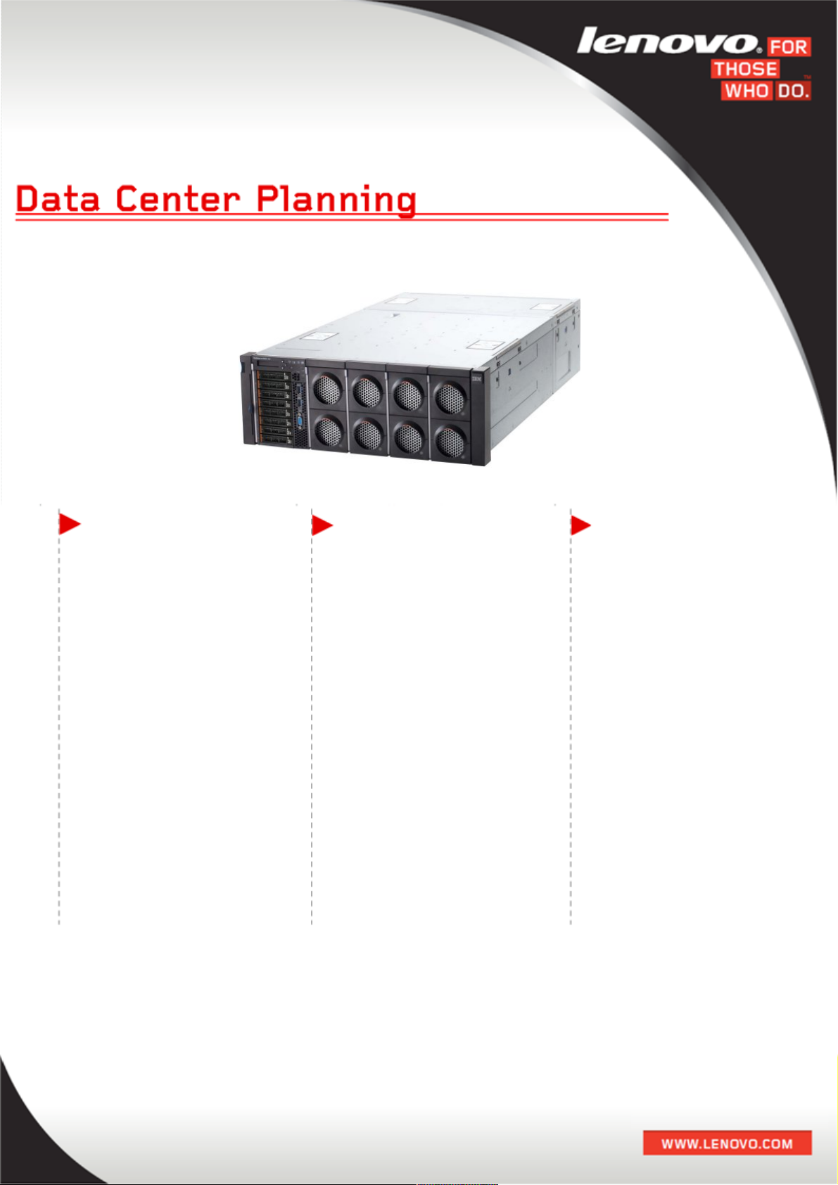
System x x3850 X6 and x3950 X6 Data Center Planning
v1.0.3
FAST, AGILE, RESILIENT CHOICE & FLEXIBILITY SUPERIOR COOLING
The sixth generation of
Enterprise X-Architecture
technology, the X6 servers
are fast in application
performance, has an agile
design and is a
resilient platform that
maximizes up time.
The x3850 X6 server
supports up to four
redundant power supplies,
and the x3950 X6 up to eight
redundant power supplies,
offering 750W, 900W or
1400W capacities to meet
your environmental needs.
The systems provide
Calibrated Vectored
Cooling™, with up to ten
redundant hot-swap fan
packs and five fan zones with
N+1 fan redundancy per
node. Each fan pack includes
two counter-rotated dualmotor fans.

.
Author:
Rani Doughty
rdoughty@lenovo.com
Questions / Comments: power@lenovo.com
Data Center Services, Enterprise Business Group
Revision History
1.0.0 – Feb 24th, 2014 Initial Release
1.0.1 – October 1st, 2014 Updates to format, contacts, webpage, and email.
1.0.2 – April 21st, 2015 Update to template
1.0.3 May 22nd, 2015 Convert to Lenovo logo IMM2
Contributors:
Jerrod Buterbaugh, System x Data Center Services
Reviewers:
Matthew Archibald, System x Data Center Services
2

.
Table of Contents
INTRODUCTION.............................................................................................................5
About This Guide....................................................................................................5
SYSTEM X X6 SYSTEM POWER OVERVIEW.........................................................................6
SYSTEM X X6 SYSTEM POWER SUPPLY UNIT (PSU)..........................................................6
900W AC PSU – Rating & Part Number Information..............................................6
1400W AC PSU – Rating & Part Number Information............................................6
750W DC PSU – Rating & Part Number Information..............................................6
80 PLUS.................................................................................................................8
X6 POWER SUPPLIES....................................................................................................9
X3850 X6 POWER SUPPLY PLACEMENT...........................................................................9
X3950 X6 POWER SUPPLY PLACEMENT.........................................................................10
POWER SUPPLY INSTALLATION AND ORDERING...............................................................11
POWER SUPPLY INPUT FEED WIRING FOR REDUNDANCY..................................................12
IMM2 POWER POLICIES..............................................................................................14
Setting a Power Policy.........................................................................................15
IMM2 POWER CAPPING AND POWER MONITORING.........................................................16
Enabling Power Capping.......................................................................................16
Power Monitoring and Power Allocation..............................................................17
Power History......................................................................................................18
SYSTEM X POWER MAXIMIZER......................................................................................19
SYSTEM X POWER CONFIGURATOR................................................................................20
SYSTEM X X6 PDU AND LINE CORD SELECTION...............................................................21
Switched and Monitored PDUs - North America..................................................21
Switched and Monitored PDUs - International.....................................................22
Enterprise PDUs - North America........................................................................23
Enterprise PDUs - International..........................................................................24
Front-end PDUs - North America........................................................................26
Front-end PDUs - International...........................................................................26
Universal Rack PDUs............................................................................................27
0U Basic PDUs - North America...........................................................................30
0U Basic PDUs - International.............................................................................30
SYSTEM X X6 POWER CORDS.......................................................................................31
System x x3850 X6 and x3950 X6 Worldwide PDU Power Cords..........................31
System x x3850 X6 and x3950 X6 North American Power Cords.........................32
System x x3850 X6 and x3950 X6 International Power Cords..............................33
TYPICAL POWER FOR COMMON X3850 X6 CONFIGURATIONS............................................34
CUSTOMIZED PDU CONFIGURATIONS............................................................................37
TYPICAL PDU CONFIGURATIONS...................................................................................37
1400W PSU Configuration Diagrams....................................................................37
900W PSU Configuration Diagrams......................................................................59
900W & 1400W PSU Combination Configuration Diagrams..................................80
System x North American PDUs Line Cords.........................................................85
System x International PDUs Line Cords..............................................................90
REFERENCE MATERIAL................................................................................................96
What is N+N and N+1 PSU Redundancy...............................................................96
3

.
N+N and N+1 Examples........................................................................................96
IEC 320 CONNECTORS................................................................................................97
IEC 320 CONNECTORS................................................................................................98
IEC 309 PIN & SLEEVE PLUG DECODE.........................................................................99
INGRESS PROTECTION (IP) DECODE...........................................................................100
60A THREE PHASE DELTA POWER CALCULATIONS........................................................100
50A THREE PHASE DELTA POWER CALCULATIONS........................................................101
30A THREE PHASE DELTA POWER CALCULATIONS........................................................101
32A THREE PHASE DELTA POWER CALCULATIONS........................................................102
16A THREE PHASE DELTA POWER CALCULATIONS........................................................102
SYSTEM X6 DOCUMENTS............................................................................................103
Helpful Links.......................................................................................................103
Support..............................................................................................................104
4

.
Introduction
The System x X6 servers are the sixth generation of servers built upon the System x
Enterprise X-Architecture. Enterprise X-Architecture is the culmination of bringing
generations of System x technology and innovation derived from our experience in
high-end enterprise servers.
The System x X6 generation server pack numerous fault-tolerant and high-availability
features into a high-density, rack-optimized, chassis-like package where all
serviceable components are front and rear accessible, significantly reducing the
space needed to support massive network computing operations and simplify
servicing.
The X6 product portfolio is based on the Intel Xeon processor E7-8800/4800 v2
product families which comprises of a 4U, 4 socket x3850 X6 server that is scalable
to an 8U, 8 socket x3950 X6 server. The X6 systems offer the new “bookshelf”
design concept that is based on a fix chassis mounted in a standard rack cabinet. The
modular components that can be installed in the chassis called “Books”, comprises of
a Compute Book, Storage Book, and I/O Book.
The x3850 X6 server contains five fan zones with space for up to two fans per zone
totaling ten hot swap fans with N+1 fan redundancy. Up to four redundant hot-swap
900W AC, 1400W AC, or 750W DC power supplies can be installed supporting N+N,
N+1, and N configurations.
The x3950 X6 server contains ten fan zones with space for up to two fans per zone
totaling twenty hot swap fans with N+1 fan redundancy. Up to eight redundant hotswap 900W AC, 1400W AC, or 750W DC power supplies can be installed supporting
N+N, N+1, and N configurations.
The System x x3850 X6 enclosure covered in this guide is currently marketed
worldwide. The intent of this guide is to provide power information for installation
planning of System x X6 System. This guide contains examples of the System x x3850
X6 enclosure connected to various PDUs and circuits.
About This Guide
When using this guide keep in mind that power connections to the System x X6
system(s) must be wired to comply with local and/or national electrical codes. Consult
your local AHJ (Authority Having Jurisdiction) to ensure compliance.
Each example covered in this guide gives System x PDU option information.
5
.
System x X6 System Power Overview
Use the Power Configurator at the link below to estimate power consumption and
heat load for System x X6 configurations.
http://www.ibm.com/support/entry/portal/docdisplay?lndocid=LNVO-PWRCONF
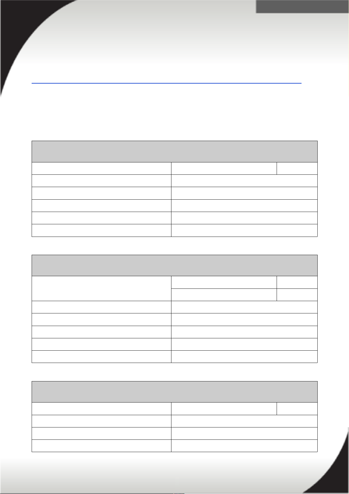
System x X6 System Power Supply Unit (PSU)
The following tables represent the technical specifications of the compatible PSUs for
the x3850 X6 and x3950 X6 servers.
900W AC PSU – Rating & Part Number Information
Power Supply Unit Part Numbers PN: 44X4132 FC: A4R0
DC Output Wattage @ 200-240V AC 900W
Max Input Amps @ 200-240V: 5A
DC Output Wattage @ 100-127V AC 900W
Max Input Amps @ 100-127V 10A
Nominal Input Voltage Range 100-127V AC & 200-240V AC @ 50-60 Hz.
1400W AC PSU – Rating & Part Number Information
Power Supply Unit Part Numbers PN: 44X4152 < 5000 altitude FC: A54E
PN: 44X4150 > 5000 altitude FC: A45D
DC Output Wattage @ 200-240V AC 1400W
Max Input Amps @ 200-240V: 8A
DC Output Wattage @ 100-127V AC 900W
Max Input Amps @ 100-127V 10A
Nominal Input Voltage Range 100-127V AC & 200-240V AC @ 50-60 Hz.
750W DC PSU – Rating & Part Number Information
Power Supply Unit Part Numbers PN: 88Y7433 FC: A2EA
DC Output Wattage @ -36V DC 750W
PSU Max Input Amps @ -36V 24A
Nominal Input Voltage Range -48V (-30V to -60V)
6
.
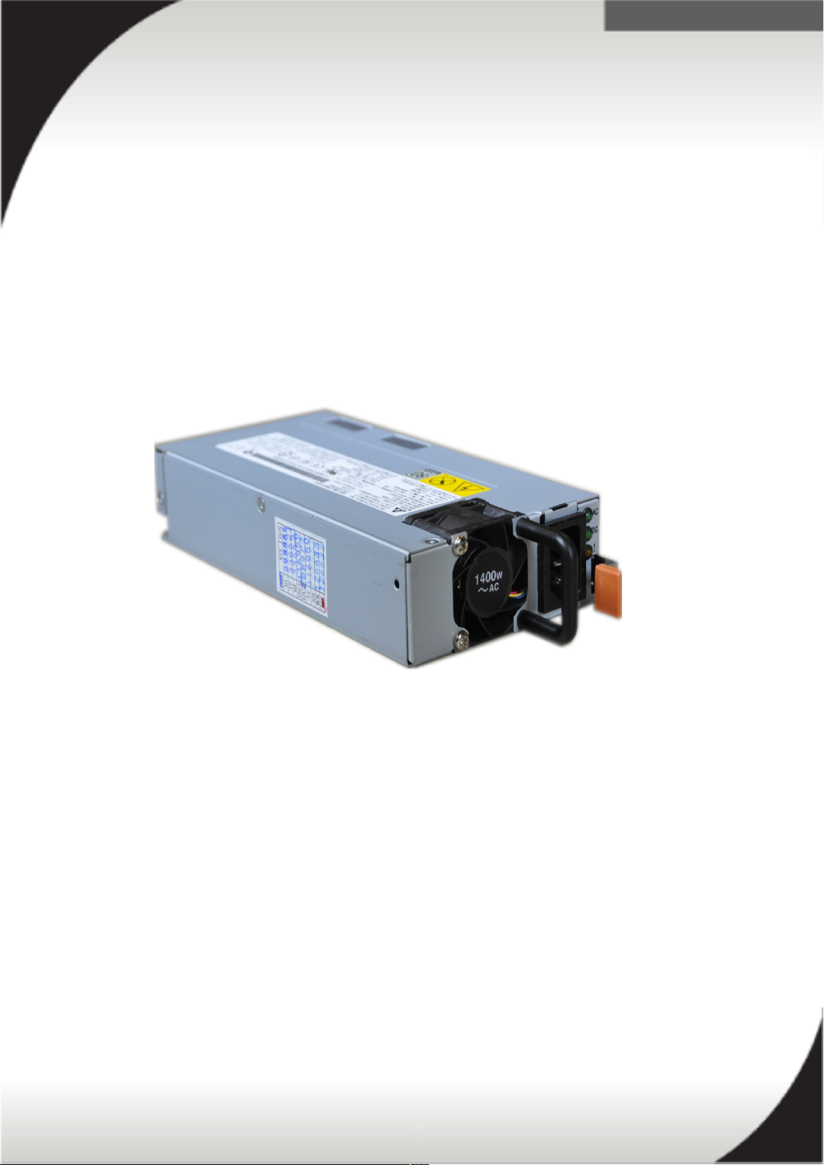
Depending on your load and power requirements, the x3850 X6 supports the
following power supply installation:
One 900W
One 1400W
Two 900W
Two 1400W
Two 900W and two 1400W
Four 900W
Four 1400W
Four 750W DC
7
Figure 1: x6 hot swap power supply
.
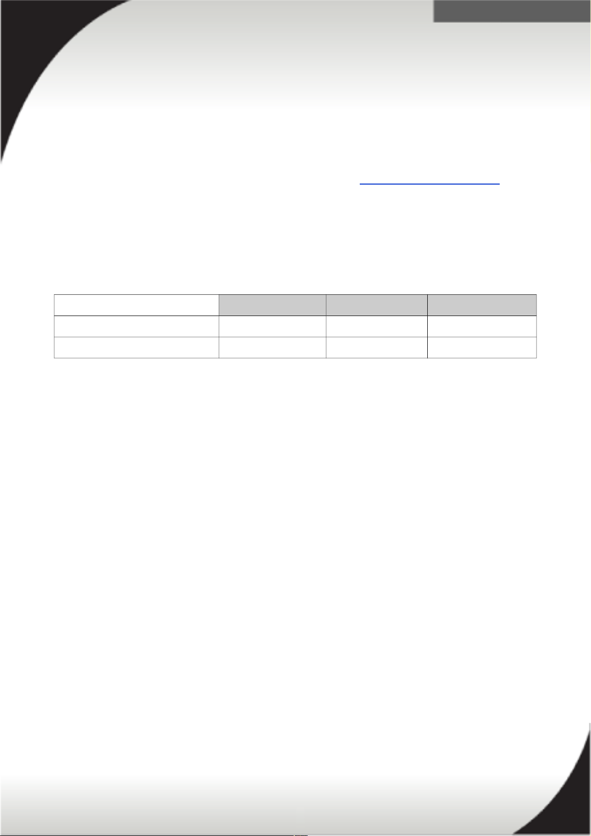
80 PLUS
80 PLUS is a performance specification for power supplies used within servers and
computers. To meet the 80 PLUS standard, the power supply must have an efficiency
of 80% or greater, at 20%, 50%, and 100% of rated load with PF of 0.9 or greater.
The standard has several grades, such as Bronze, Silver, Gold, Platinum, and
Titanium. More information on 80 PLUS is available at http://www.80PLUS.org.
The power supplies used in System x X6 Systems are hot-swap high efficiency 80
PLUS Platinum power supplies operating at 94% efficiency. The efficiency varies by
load as shown in the table below.
Power Efficiencies at Different Load Levels
20% load 50% load 100% load
80 PLUS Platinum standard 90.00% 94.00% 91.00%
System x X6 1400W PSU 93.62% 94.21% 91.85%
8
.
X6 Power Supplies
The following section covers the x3850 X6 and x3950 X6 power supplies unit (PSU)
installation order and placement rules. Input feed wiring for redundancy is also
discussed.
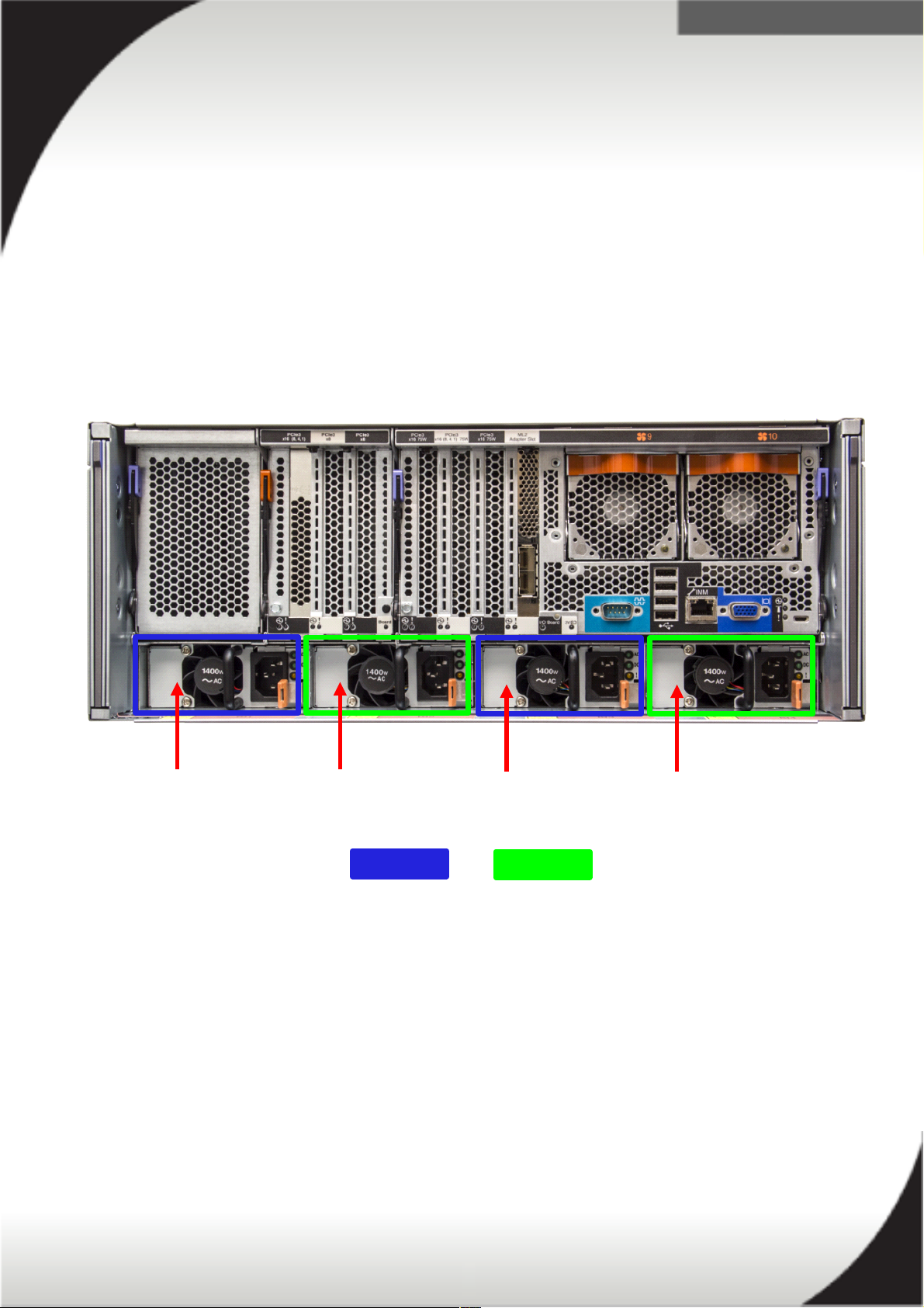
x3850 X6 Power Supply Placement
The power supplies are labeled from left to right when viewed from the rear of the
server and are grouped in pairs as seen in the following picture. Group A (blue)
consists of PSU bay 1 and 3 and Group B (green) consists of PSU bay 2 and 4.
PSU Bay 1 PSU Bay 2 PSU Bay 3 PSU Bay 4
Group A Group B
9
.
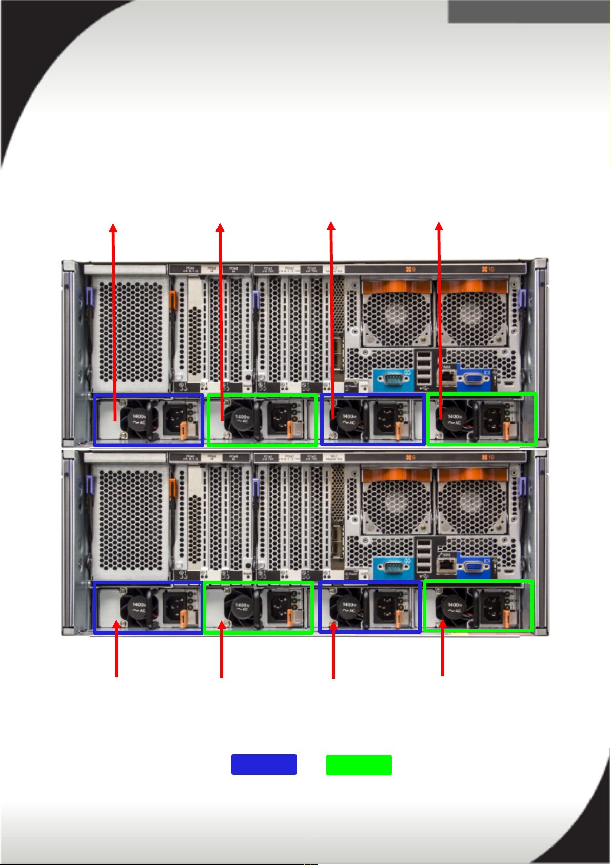
x3950 X6 Power Supply Placement
The power supplies are labeled from left to right when viewed from the rear of the
server and are grouped in pairs as seen in the following picture. Group A (blue)
consists of PSU bay 1, 3, 5 and 7 and Group B (green) consists of PSU bay 2, 4, 6
and 8.
PSU Bay 5 PSU Bay 6 PSU Bay 7 PSU Bay 8
PSU Bay 1 PSU Bay 2 PSU Bay 3 PSU Bay 4
Group A Group B
10

.
Power Supply Installation and Ordering
The following rules apply when installing 1, 2, and 4 AC and DC PSUs in the x3850 X6
system.
For a 1 PSU installation, install the PSU in bay 3. Fillers must be installed in
bays 1, 2, and 4.
For a 2 PSU installation, install the PSU in bay 2 and 3. Fillers must be installed
in bays 1 and 4. Ensure both PSUs are of the same wattage (both 900W or
both 1400W only). Install each supply on separate power feeds for power
redundancy.
For a 4 PSU installation, install the PSUs in all bays.
The 750W DC power supply requires all 4 PSUs to be installed together.
Due to the smaller size of the 900W and 750W PSUs a mechanical filler is
installed in the bay along with the PSU.
Mixing of AC and DC power supplies is not supported.
The suggested power installation order for a x3850 X6 is as follows:
PS Bay 3 – 1st power supply to be installed
PS Bay 2 – 2nd power supply to be installed
PS Bay 1 – 3rd power supply to be installed
PS Bay 4 – 4th power supply to be installed
Note: 1, 2 or 4 PSU configurations are supported. 3 PSU configurations are not
supported.
The suggested power installation order for a x3950 X6 is as follows:
PS Bay 3 – 1st power supply to be installed
PS Bay 2 – 2nd power supply to be installed
PS Bay 7 – 3rd power supply to be installed
PS Bay 6 – 4th power supply to be installed
PS Bay 1 – 5th power supply to be installed
PS Bay 4 – 6th power supply to be installed
PS Bay 5 – 7th power supply to be installed
PS Bay 8 – 8th power supply to be installed
Note: 4 or 8 PSU configurations are supported. All other combinations (1, 2, 3, 5, 6,
and 7) are not supported.
Use the System x Power Configurator tool to calculate your total power draw and
assist you in determining the type and number of PSUs required.
11

.
In a 4 PSU configuration, mixing of 900W PSUs and 1400W PSUs is allowed. The
following rules apply when mixing PSUs.
A mixture of 900W and 1400W PSUs must be installed in group A and group B.
Example:
Bay 1 (group A) = 900W
Bay 2 (group B) = 1400W
Bay 3 (group A) = 1400W
Bay 4 (group B) = 900W
Power Supply Input Feed Wiring for Redundancy
The IMM2 Code for the x3850 X6 server requires power supplies in bays 1 and 3 to
be wired to feed 1, and power supplies in bays 2 and 4 to be wired to feed 2.
This is due to how the power supplies are internally connected and how the IMM2
determines if the system is redundant based on the
power policy
selected. If the
power supplies are not correctly connected, the selected IMM2 power policy may not
function as intended. Power policies are discussed in the next section.
The following rules apply when connecting the server to input feeds for redundancy.
PSUs in group A and PSUs in group B must be balanced in both quantity and
power output (A=B). If the groups are not balanced, the system will not boot.
As an example, mixed wattages must be balanced:
Feed 1 (group A) = 900W and 1400W PSUs
Feed 2 (group B) = 900W and 1400W PSUs
Input power feeds for both group A and group B must be different for
redundancy. Example of a 2 PSU installation.
PSU 1 (group A) = Feed 1
PSU 2 (group B) = Feed 2
Input power feeds for both group A and group B must be different for
redundancy. Example of a 4 PSU installation.
PSU 1 (group A) = Feed 1
PSU 2 (group B) = Feed 2
PSU 3 (group A) = Feed 1
PSU 4 (group B) = Feed 2
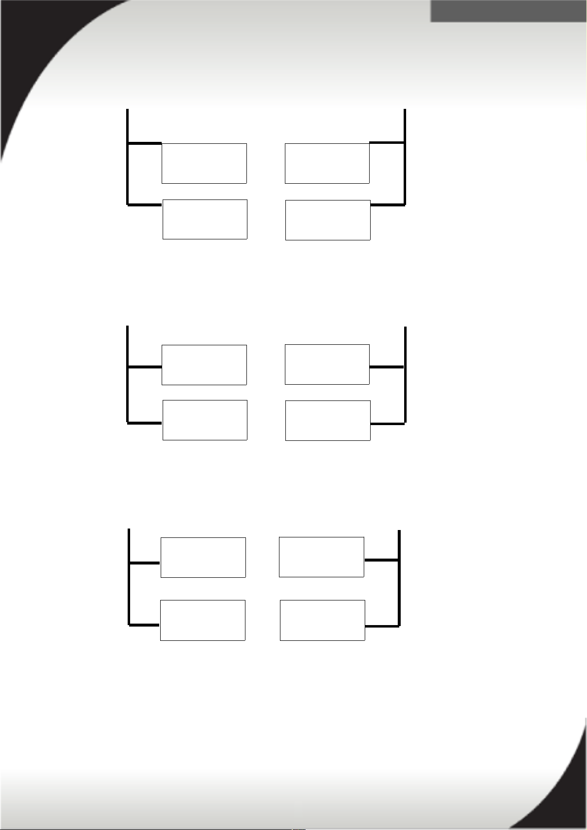
The following illustrations depict how a x3850 X6 server should be wired for
redundancy in a 2 PSU configuration, a 4 PSU configuration, and a mixed wattage
configuration.
12
.
Example of input feed wiring for 2 x 1400W PSUs:
Feed 1 Feed 2
Group A Group B
Example of input feed wiring for 4 x 900W PSUs:
Feed 1 Feed 2
Group A Group B
Example of input feed wiring for 2 x 900W and 2 x 1400W PSUs:
Feed 1 Feed 2
Group A Group B
13
PS 1, Bay 3
1400W
PS 3, Bay 1
Empty
PS 2, Bay 2
1400W
PS 4, Bay 4
Empty
PS 1, Bay 3
900W
PS 3, Bay 1
900W
PS 2, Bay 2
900W
PS 4, Bay 4
900W
PS 1, Bay 3
1400W
PS 3, Bay 1
900W
PS 2, Bay 2
1400W
PS 4, Bay 4
900W
.
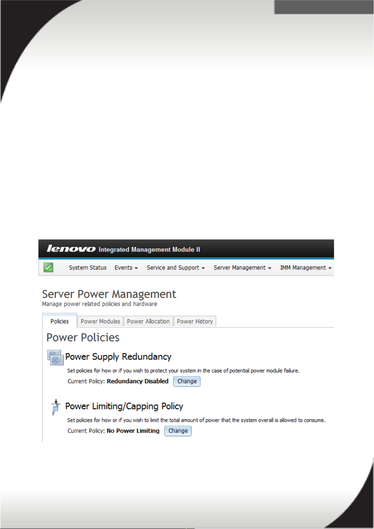
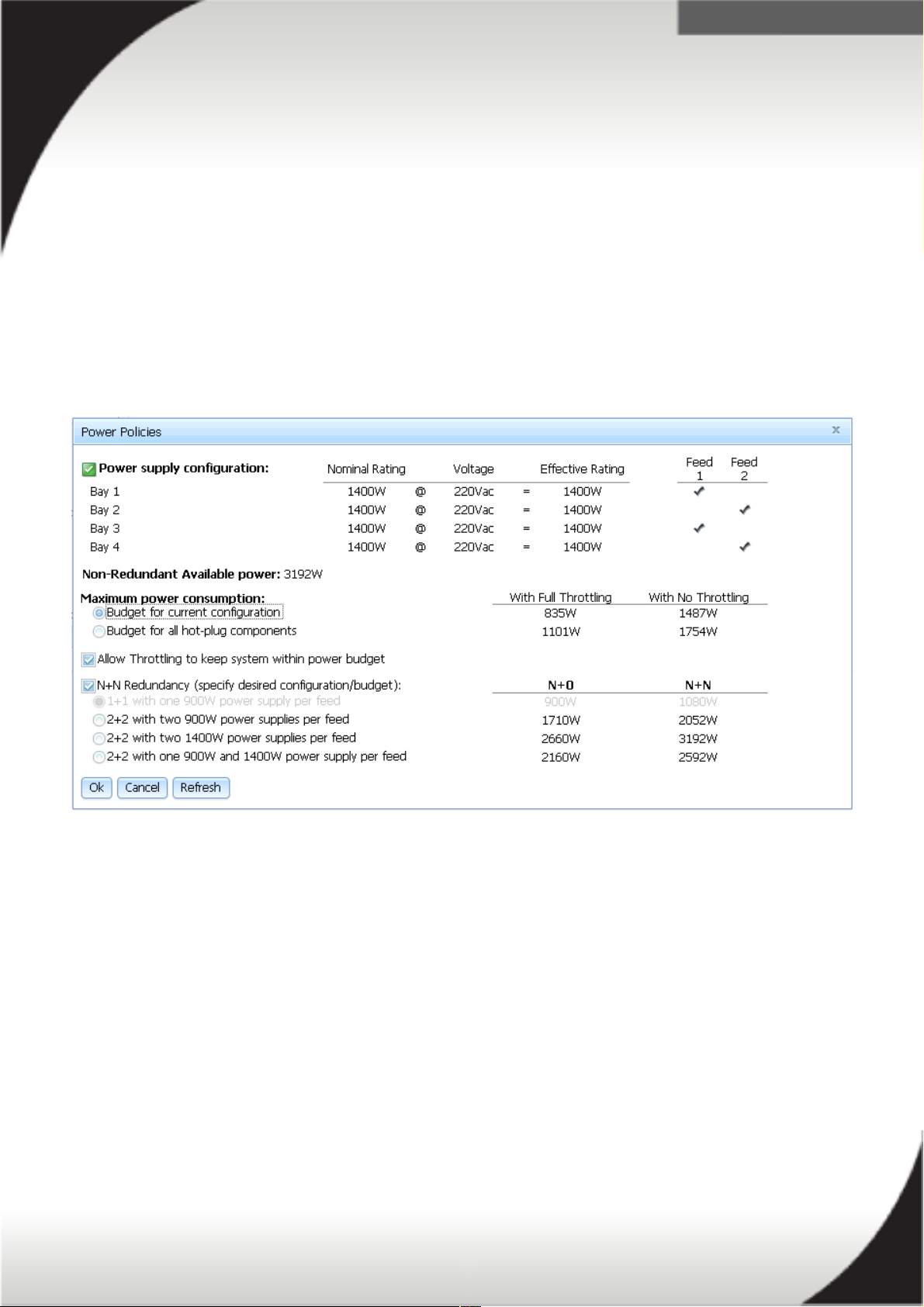
IMM2 Power Policies
As previously mentioned, the IMM2 code controls the x3850 X6 and x3950 X6 power
policy. The servers support three modes of redundancy based on the power supply
configuration, system load and the Power Policy configuration controlled by the
IMM2:
Non-redundant
Fully system redundant
Redundant with reduced performance (throttling)
When the server is booting,
Power Maximizer
runs in the background to verify the
available power in the system. If Power Maximizer determines the available power in
the system does not meet the systems power load based on the hardware installed,
and does not meet the Power Policy chosen in the IMM2, the system will not be
allowed to boot. Power Maximizer is discussed further in the following sections.
The below image is a screenshot of the IMM2 Server Power Management page where
you can change the servers power policies.
14
.
Setting a Power Policy
The default power policy configuration setting for both AC and DC models is NonRedundant with Throttling enabled. This is to ensure the server will boot the first time
regardless of the installed hardware or if you have not yet implemented a power
policy.
You can set and change the Power Policy and System Power Configurations using the
IMM2 web interface. The power configurations and policies can be changed via the
web, CIM and ASU interfaces. These settings cannot be changed by UEFI. The
following figure is the IMM2 power policy page.
15
.
IMM2 Power Capping and Power Monitoring
The 'Server Management Power' page in the IMM2 settings allows for power capping
(throttling) and power allocation and monitoring of the X6 hardware to help manage
the systems power usage and consumption. The following sections discusses both of
these features of the IMM2.
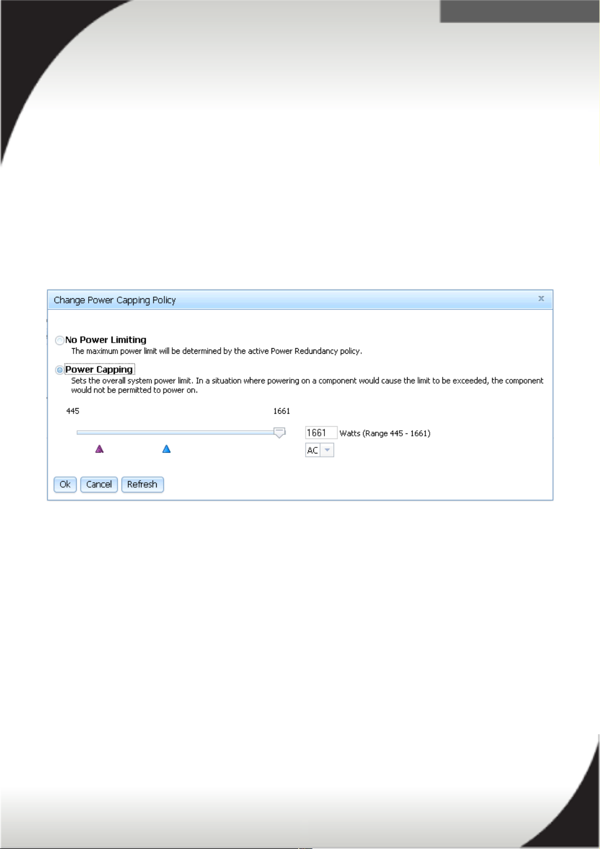
Enabling Power Capping
From the IMM2 'Server Power Management' page, under the 'Policies' tab, you can
set 'Power Limiting/Power Capping'. The below image is a screenshot of the power
capping policy page. Note that setting a power capacity limit works by throttling the
hardware's performance (such as the CPU) so it will produce less power.
Ensure you confirm your servers power consumption via the power monitoring tools
in the IMM2. The power monitoring and allocation tool is discussed in the next
section. You do not want to set the power capacity limit too low and risk exceeding the
power capacity limit. In the event you exceed the power capacity limit the server
and/or some of its components may not power on.
16
.
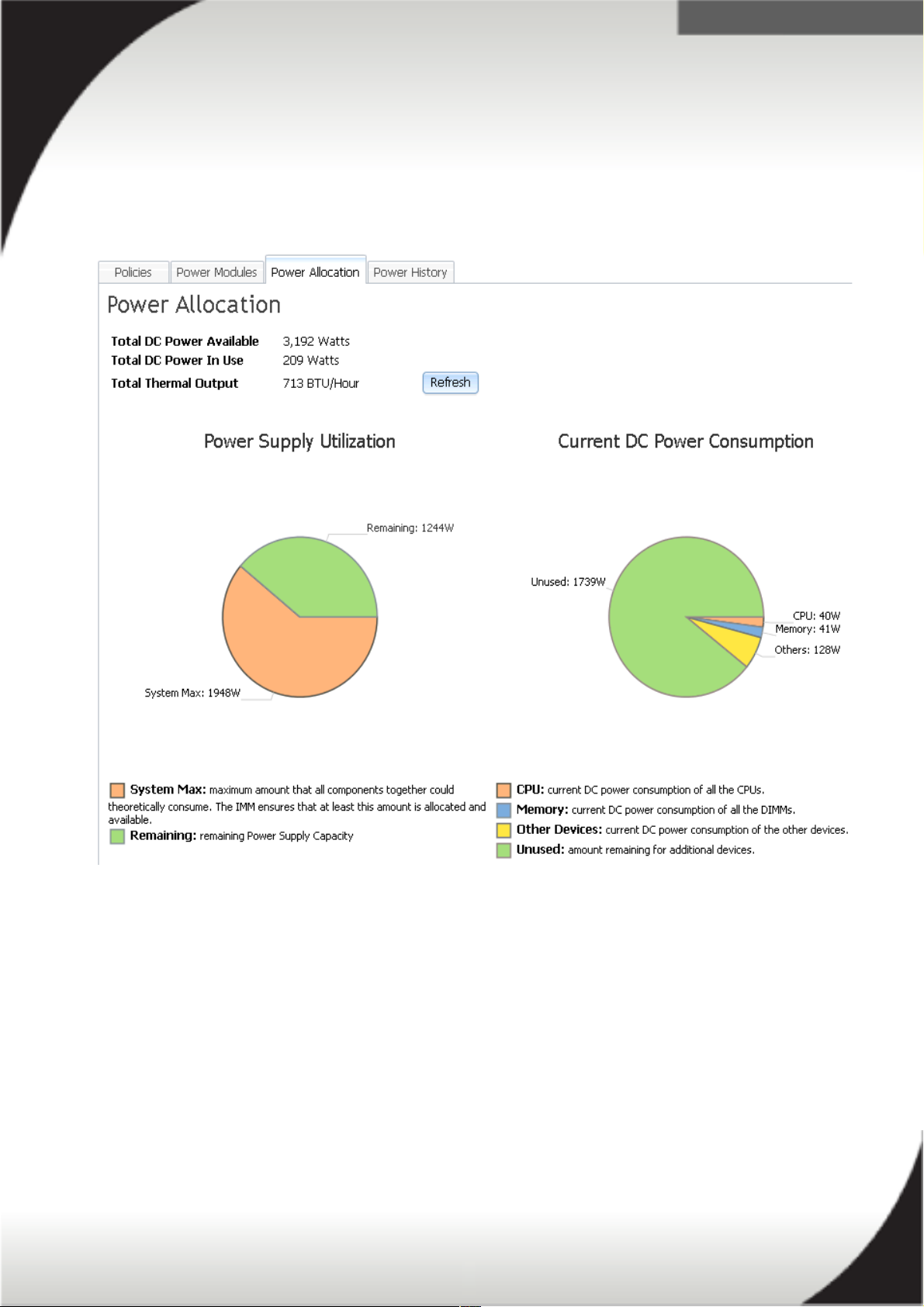
Power Monitoring and Power Allocation
The 'Server Power Management' page contains information on the power supply
utilization and the DC power consumption of your server. The below image is a screen
shot of this page from the IMM2.
The wattage calculated for the power supply utilization and the DC power
consumption is only the theoretically amount of power that all components installed in
your server could potentially consume. It is not a picture of the servers real-time
power usage. For real-time AC power usage use the 'Power History' tab, which is
discussed in the next section.
The IMM2 will use the power supply utilization information and the DC power
consumption information to ensure the server has enough power source(s) installed
to power all of the hardware. If the IMM2 detects insufficient power source(s)
available it may not turn all of the servers components on or the server itself may not
turn on at all.
17
.
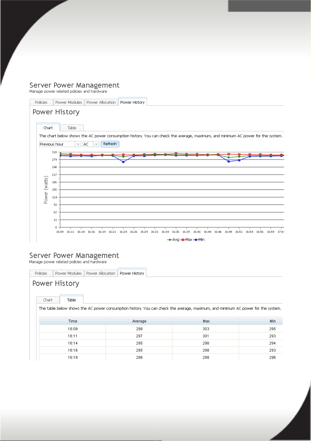
Power History
The 'Server Power Management' page contains information on the history of your
power consumption. This is found under the 'Power History' tab. The below images
are screen shots of a servers power history in chart and table format. You can view
the history of the servers AC or DC power consumption in minutes, hours or days.
18

.
System x Power Maximizer
System x Power Maximizer is an integrated software tool for determining the asconfigured total power budget for all new System x, Pure Flex, iDataPlex, and
NeXtScale systems. This technology takes a more granular approach of determining
system and chassis power budget than using look-up tables in system management
devices. The benefits of this allow power policies to be set based on actual
component power consumption under any supported operating condition or workload.
Power policies are able to be more accurately maintained without unnecessary overbudgeting to ensure as much available power is provisioned by the system as the
policies allow. This prevents resiliency and performance impacts such as unexpected
throttling and system nodes powering off unexpectedly.
The System x Power Maximizer functions by running separate, sub-system specific
workloads and then calculates a total worst-case power consumption estimate. The
result of the System x Power Maximizer is reported to the respective management
interhttp://www.Systemx.com/systems/bladecenter/resources/powerconfig.htmlfac
e for determining power-on support and redundancy policy of the supported systems.
The System x Power Maximizer result is not directly reported to any user interface,
but the power policies are managed by this configuration specific power budget. This
means that as the configurations change, the enclosure will automatically manage the
provisioned power according to the power policy set by the end user.
19

.
System x Power Configurator
The System x Power Configurator is a software tool designed to assist with
calculating System x Systems environmental information. The data in the System x
Power Configurator tool is derived from running real-world workloads across a
number of configurations to properly characterize component power consumption
under various conditions. The current workloads are a combination of Floating Point
and Small FFT Processor workloads as well as running configuration-tuned versions
of HPL (Portable Implementation of the High-Performance Linpack Benchmark) and
Stream to exercise multiple sub-systems of the IT systems. The two highest power
consuming sub-systems in a non-HPC (High Performance Computing) IT system are
processor and memory, so focus is given to exercising those sub-systems to correctly
model power consumption under traditional and virtual workloads. For HPC type IT
systems, some configurations contain GPGPU (General Purpose Graphical
Processing Unit) or MIC (Many Integrated Core) I/O adapters. These adapters are
characterized by running highly parallel graphic rendering workloads for complete
characterization. All tests are conducted using default uEFI/BIOS settings.
The System x Power Configurator provides three groups of environmental
information. The first represents Idle or minimum power consumption, the second is
Maximum power consumption, and the third is Load Factor. Load Factor is a scale
factor between Idle and Max that can represent any configurations total aggregate
system utilization for a specific workload.
The data reported by System x Power Configurator can be used in certain cases to
determine electrical wiring and levels of redundancy. The data reported by System x
Power Configurator represents a worst-case power consumption value under normal
operating conditions and may not model power consumption under component failure
conditions. Final determinations should be made by persons skilled in the art or by
contacting power@us.System x.com for assistance.
System x Power Configurator tool:
http://www.ibm.com/support/entry/portal/docdisplay?lndocid=LNVO-PWRCONF
20

.
System x X6 PDU and line cord selection
Some PDUs have attached line cords while others require a line cord to be ordered
separately based on your requirement of Three-phase power or Single-phase power.
Refer to the following table for line cord and phase options for both North America
and International PDUs.
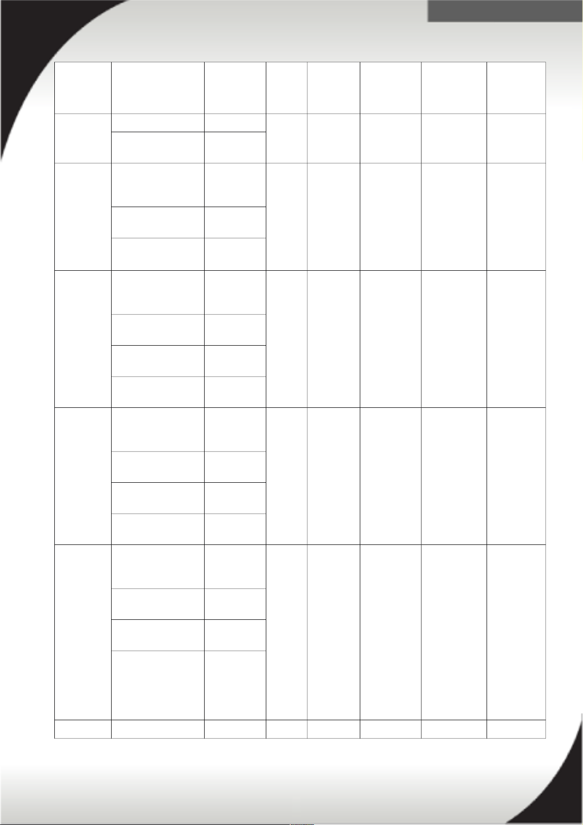
Part
Number
Description Line cord
part
number
Phase
(ph)
Voltage
(V)
Line cord
rating
(Derated)
Line cord
plug
Number /
Type of
outlet
Switched and Monitored PDUs - North America
46M4002 System x 1U 9 C19/3
C13 Active Energy
Manager (AEM) DPI
PDU
40K9614 1ph 200V-
240V
30A (24A) NEMA L6
30P
9 / C19
3 / C13
40K9615 1ph 200V-
240V
60A (48A) IEC 309
2P+G
46M4003 System x 1U 9 C19/3
C13 AEM 60A 3
Phase PDU
Attached 3ph Δ 208V 60A
(27.7A/ph)
IEC 309
3P+G
9 / C19
3 / C13
46M4004 System x 1U 12 C13
AEM DPI PDU
40K9614 1ph 200V-
240V
30A (24A) NEMA L6
30P
12 / C13
40K9615 1ph 200V-
240V
60A (48A) IEC 309
2P+G
46M4005 System x 1U 12 C13
AEM 60A 3 Phase
PDU
Attached 3ph Δ 208V 60A
(27.7A/ph)
IEC 309
3P+G
12 / C13
46M4167 System x 1U 9 C19/3
C13 Switched and
Monitored 30A 3
Phase PDU
Attached 3ph Δ 208V 30A
(13.85A/ph)
NEMA
L21-30P
9 / C19
3 / C13
46M4116 System x 0U 24 C13
Switched and
Monitored 30A PDU
Attached 1ph 200V-
240V
30A (24A) NEMA L6
30P
24 / C13
46M4134 System x 0U 12
C19/12, C13
Switched and
Monitored 50A 3
Phase PDU
Attached 3ph Δ 208V 50A
(23.09A/ph)
CS8365L 12 / C19
12 / C13
21

.
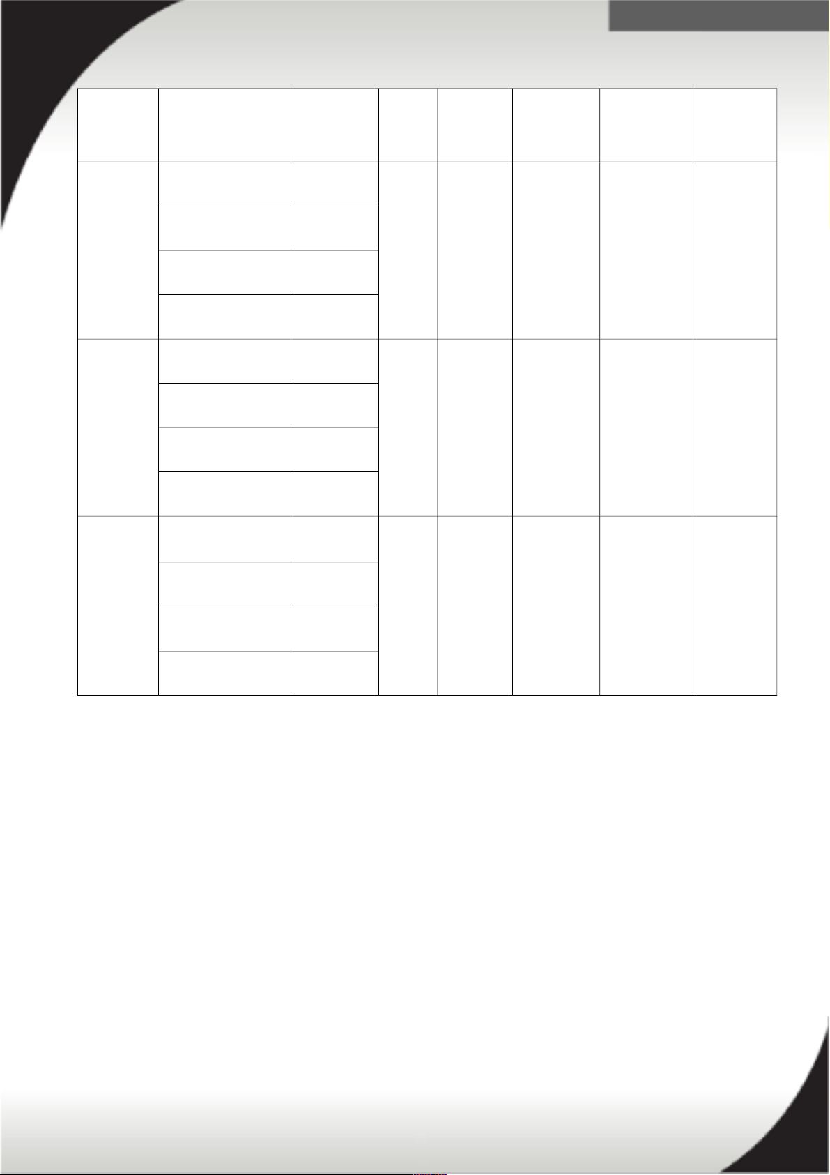
Part
Number
Description Line cord
part
number
Phase
(ph)
Voltage
(V)
Line cord
rating
(Derated)
Line cord
plug
Number /
Type of
outlet
Switched and Monitored PDUs - International
46M4119 System x 0U 24 C13
Switched and
Monitored 32A PDU
Attached 1ph 220V-
240V
32A IEC 309
P+N+G
24 / C13
46M4137 System x 0U 12
C19/12
C13 Switched and
Monitored 32A 3
Phase PDU
Attached 3ph Y 380V-
415V
32A
(32A/ph)
IEC 309
3P+N+G
12 / C19
12 / C13
46M4002 System x 1U 9
C19/3 C13 Active
Energy Manager
DPI PDU
40K9612 1ph 220V-
240V
32A IEC 309
P+N+G
9 / C19
3 / C13
40K9613 1ph 220V-
240V
63A IEC 309
P+N+G
40K9617 1ph 230V-
240V
32A AUS/NZ
3112
40K9618 1ph 220V 30A KSC 8305
40K9611 3ph Y 380V-
415V
32A
(32A/ph)
IEC 309
3P+N+G
47C2495 3ph Y 380V-
415V
16A
(16A/ph)
IEC 309
3P+N+G
46M4004 System x 1U 12 C13
AEM DPI PDU
40K9612 1ph 220V-
240V
32A IEC 309
P+N+G
12 / C13
40K9613 1ph 220V-
240V
63A IEC 309
P+N+G
40K9617 1ph 230V-
240V
32A AUS/NZ
3112
40K9618 1ph 220V 30A KSC 8305
40K9611 3ph Y 380V-
415V
32A
(32A/ph)
IEC 309
3P+N+G
47C2495 3ph Y 380V-
415V
16A
(16A/ph)
IEC 309
3P+N+G
22
.
Part
Number
Description Line cord
part
number
Phase
(ph)
Voltage
(V)
Line cord
rating
(Derated)
Line cord
plug
Number /
Type of
outlet
Enterprise PDUs - North America
71762NX System x Ultra
Density
Enterprise 1U PDU
C19 PDU
40K9614 1ph 200V-
240V
30A (24A) NEMA
L6-30P
9 / C19
3 / C13
40K9615 1ph 200V-
240V
60A (48A) IEC 309
2P+G
71763MU System x Ultra
Density
Enterprise 1U PDU
C19 3 Phase 60A
PDU+ Monitored
Attached 3ph 208V 60A
(27.7A/ph)
IEC 309
2P+G
9 / C19
3 / C13
71763NU System x Ultra
Density
Enterprise 1U PDU
C19 3 Phase 60A
PDU Basic
Attached 3ph Δ 208V 60A
(27.7A/ph)
IEC 309
2P+G
9 / C19
3 / C13
39M2816 System x DPI C13
Enterprise 1U PDU+
without line cord
Monitored
40K9614 1ph 200V-
240V
30A (24A) NEMA
L6-30P
12 / C13
40K9615 1ph 200V-
240V
60A (48A) IEC 309
2P+G
39Y8941 DPI Single Phase
C13 Enterprise 1U
PDU without line
cord
40K9614 1ph 200V-
240V
30A (24A) NEMA
L6-30P
12 / C13
40K9615 1ph 200V-
240V
60A (48A) IEC 309
2P+G
39Y8948 DPI Single Phase
C19 Enterprise 1U
PDU without line
cord
40K9614 1ph 200V-
240V
30A (24A) NEMA
L6-30P
6 / C19
40K9615 1ph 200V-
240V
60A (48A) IEC 309
2P+G
39Y8923 DPI 60A Three
Phase C19
Enterprise 1U PDU
with IEC309 3P+G
(208 V) fixed line
cord
Attached 3ph Δ 208V 60A
(27.7A/ph)
IEC 309
3P+G
6 / C19
23
.
Part
Number
Description Line cord
part
number
Phase
(ph)
Voltage
(V)
Line cord
rating
(Derated)
Line cord
plug
Number /
Type of
outlet
Enterprise PDUs - International
71762NX System x Ultra
Density
Enterprise 1U PDU
C19 PDU (WW)
40K9612 1ph 220V-
240V
32A IEC 309
P+N+G
9 / C19
3 / C13
40K9613 1ph 220V-
240V
63A IEC 309
P+N+G
40K9617 1ph 230V-
240V
32A AUS/NZ
3112
40K9618 1ph 220V 30A KSC 8305
40K9611 3ph Y 380V-
415V
32A
(32A/ph)
IEC 309
3P+N+G
47C2495 3ph Y 380V-
415V
16A
(16A/ph)
IEC 309
3P+N+G
71762MX System x Ultra
Density
Enterprise PDU
C19 1U PDU+ (WW)
40K9612 1ph 220V-
240V
32A IEC 309
P+N+G
9 / C19
3 / C13
40K9613 1ph 220V-
240V
63A IEC 309
P+N+G
40K9617 1ph 230V-
240V
32A AUS/NZ
3112
40K9618 1ph 220V 30A KSC 8305
40K9611 3ph Y 380V-
415V
32A
(32A/ph)
IEC 309
3P+N+G
47C2495 3ph Y 380V-
415V
16A
(16A/ph)
IEC 309
3P+N+G
39M2816 System x DPI C13
Enterprise 1U PDU
without line cord
Monitored
40K9612 1ph 220V-
240V
32A IEC 309
P+N+G
12 / C13
40K9613 1ph 220V-
240V
63A IEC 309
P+N+G
40K9617 1ph 230V-
240V
32A AUS/NZ
3112
40K9618 1ph 220V 30A KSC 8305
40K9611 3ph Y 380V-
415V
32A
(32A/ph)
IEC 309
3P+N+G
47C2495 3ph Y 380V-
415V
16A
(16A/ph)
IEC 309
3P+N+G
24
.
Part
Number
Description Line cord
part
number
Phase
(ph)
Voltage
(V)
Line cord
rating
(Derated)
Line cord
plug
Number /
Type of
outlet
39Y8941 DPI Single Phase
C13 Enterprise 1U
PDU without line
cord
40K9612 1ph 220V-
240V
32A IEC 309
P+N+G
12 / C13
40K9613 1ph 220V-
240V
63A IEC 309
P+N+G
40K9617 1ph 230V-
240V
32A AUS/NZ
3112
40K9618 1ph 220V 30A KSC 8305
40K9611 3ph Y 380V-
415V
32A
(32A/ph)
IEC 309
3P+N+G
47C2495 3ph Y 380V-
415V
16A
(16A/ph)
IEC 309
3P+N+G
39Y8948 DPI Single Phase
C19 Enterprise 1U
PDU
without line cord
40K9612 1ph 220V-
240V
32A IEC 309
P+N+G
6 / C19
40K9613 1ph 220V-
240V
63A IEC 309
P+N+G
40K9617 1ph 230V-
240V
32A AUS/NZ
3112
40K9618 1ph 220V 30A KSC 8305
40K9611 3ph Y 380V-
415V
32A
(32A/ph)
IEC 309
3P+N+G
47C2495 3ph Y 380V-
415V
16A
(16A/ph)
IEC 309
3P+N+G
25

.
Part
Number
Description Line cord
part
number
Phase
(ph)
Voltage
(V)
Line cord
rating
(Derated)
Line cord
plug
Number /
Type of
outlet
Front-end PDUs - North America
39Y8938 30 amp/125V
Front-end PDU
Included 1ph 125V 30A (24A) NEMA
L5-30P
3 / C19
39Y8939 30 amp/240V
Front-end ½ U PDU
Included 1ph 200V-
240V
30A (24A) NEMA
L6-30P
3 / C19
39Y8940 60 amp Front-end
½ U PDU
Included 1ph 200V-
240V
60A (48A) IEC 309
2P+G
3 / C19
Front-end PDUs - International
39Y8934 DPI 32 amp Front-
end ½ U PDU
Included 1ph 200V-
240V
32A IEC 309
P+N+G
3 / C19
39Y8935 DPI 63 amp Front-
end ½ U PDU
Included 1ph 200V-
240V
63A IEC 309
P+N+G
3 / C19
26
.
Part
Number
Description Line cord
part
number
Phase
(ph)
Voltage
(V)
Line cord
rating
(Derated)
Line cord
plug
Number /
Type of
outlet
Universal Rack PDUs
39Y8951 DPI Universal Rack
PDU with US LV
and HV LC
Included 1ph 200V-
240V
20A IEC 320
C19 to
C20
7 / C13
Optional line cord
2.0m
39M5388
39Y8952 DPI Universal Rack
1U PDU with
CEE7-VII Europe
LC
1
Included 1ph 230V 16A CEE7-VII
Europe
7 / C13
Optional line cord
1.8m
39M5281
Optional line cord
2.5m
39M5282
Optional line cord
4.3m
39M5283
39Y8953 DPI Universal Rack
1U PDU with
Denmark LC
Included 1ph 230V 16A 309 P+N+G 7 / C13
Optional line cord
1.8m
39M5321
Optional line cord
2.5m
39M5322
Optional line cord
4.3m
39M5323
39Y8954 DPI Universal Rack
1U PDU with Israel
LC
Included 1ph 220V 16A Israel SI-32 7 / C13
Optional line cord
1.8m
39M5309
Optional line cord
2.5m
39M5310
Optional line cord
4.3m
39M5311
39Y8955 DPI Universal Rack
1U PDU with Italy
LC
Included 1ph 230V 16A Italy CEI 23-167 / C13
Optional line cord
1.8m
39M5297
Optional line cord 39M5298
1. While line cord Amperage (A) varies from country to country the Universial Rack PDU has a 15A internal breaker and
is limited to 15A.
27
.
Part
Number
Description Line cord
part
number
Phase
(ph)
Voltage
(V)
Line cord
rating
(Derated)
Line cord
plug
Number /
Type of
outlet
2.5m
Optional line cord
4.3m
39M529
39Y8956 DPI Universal Rack
1U PDU with South
Africa LC
Included 1ph 220V-
250V
16A South Africa
SABS 164
7 / C13
Optional line cord
2.5m
39M5290
Optional line cord
4.3m
39M5291
39Y8957 DPI Universal Rack
1U PDU with UK
LC
2
Included 1ph 230V 13A UK BS
1363/A
7 / C13
Optional line cord
1.8m
39M5293
Optional line cord
2.5m
39M5294
Optional line cord
4.3m
39M5294
39Y8958 DPI Universal Rack
1U PDU with
AUS/NZ LC
Included 1ph 230V-
240V
15A Aus/NZ
3112
Australia/NZ
7 / C13
Optional line cord
1.8m
39M5329
Optional line cord
2.5m
39M5330
Optional line cord
4.3m
39M5331
39Y8959 DPI Universal Rack
1U PDU with China
LC
Included 1ph 220V 16A China GB
2099.1
7 / C13
Optional line cord
1.8m
39M5353
Optional line cord
2.5m
39M5354
Optional line cord
4.3m
39M5355
39Y8962 DPI Universal Rack Included 1ph 220V 16A Argentina 7 / C13
2. The Universal Rack PDU is limited to 13A total capacity due to the line cord current capacity of 13A.
28
.
Part
Number
Description Line cord
part
number
Phase
(ph)
Voltage
(V)
Line cord
rating
(Derated)
Line cord
plug
Number /
Type of
outlet
1U
PDU (Argentina)
IRAM 2073
Optional line cord
1.8m
39M5341
Optional line cord
2.5m
39M5342
Optional line cord
4.3m
39M5343
39Y8960 DPI Universal Rack
1U PDU (Brazil)
Included 1ph 220V-
240V
15A Brazil NBR
14136
7 / C13
Optional line cord
1.8m
39M5357
Optional line cord
2.5m
39M5358
Optional line cord
4.3m
39M5359
39Y8961 DPI Universal Rack
1U PDU (India)
Included 1ph 230V 16A India IS
6538
7 / C13
Optional line cord
1.8m
39M5444
Optional line cord
2.5m
39M5445
Optional line cord
4.3m
39M5446
29
.
Part
Number
Description Line cord
part
number
Phase
(ph)
Voltage
(V)
Line cord
rating
(Derated)
Line cord
plug
Number /
Type of
outlet
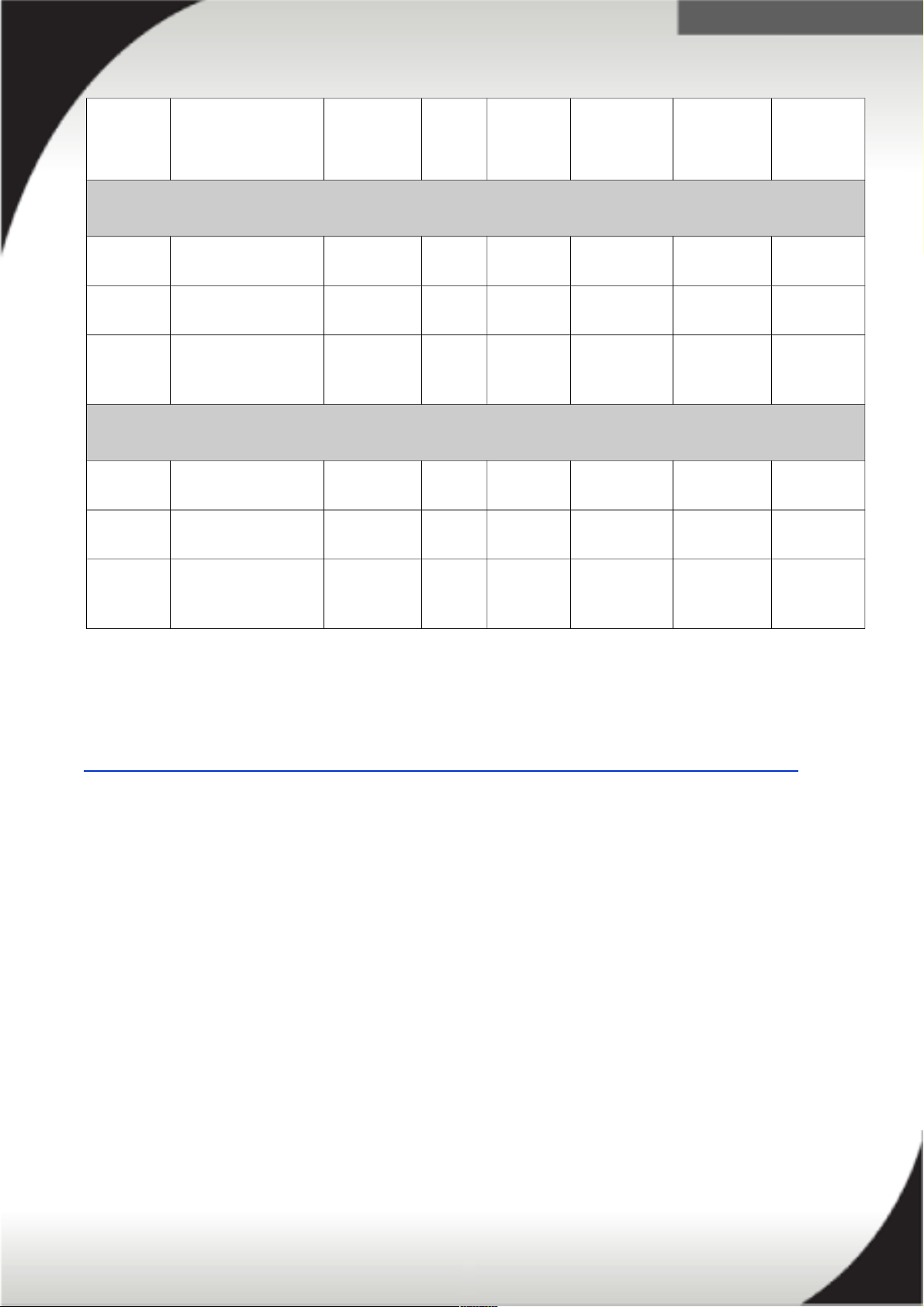
0U Basic PDUs - North America
46M4128 System x 0U 24 C13
30A PDU
Attached 1ph 200V-
240V
30A (24A) NEMA L6-
30P
24 / C13
46M4125 System x 0U 24 C13
30A 3ph PDU
Attached 3ph Δ 208V 30A
(13.85A/ph)
NEMA
L21-30P
24 / C13
46M4140 System x 0U 12
C19/12
C13 60A 3ph PDU
Attached 3ph Δ 208V 50A
(23.09A/ph)
CS8365L 12 / C19
12 / C13
0U Basic PDUs - International
46M4131 System x 0U 24 C13
32A PDU
Attached 1ph 200V-
240V
32A IEC 309
P+N+G
24 / C13
46M4122 System x 0U 24 C13
16A 3ph PDU
Attached 3ph Y 380V-
415V
16A
(16A/ph)
IEC 309
3P+N+G
24 / C13
46M4143 System x 0U 12
C19/12
C13 32A 3ph PDU
Attached 3ph Y 380V-
415V
32A
(32A/ph)
IEC 309
3P+N+G
12 / C19
12 / C13
See the “System x PDU Technical Reference – North America” and the “System x
PDU Technical Reference – International”, for more information on System x’s
System x PDUs.
http://www.ibm.com/support/entry/portal/docdisplay?lndocid=LNVO-PWRCONF
30
 Loading...