

Lenovo x3550 M4 Installation And Service Manual

System x3550 M4
Ty pe 7914
Installation and Service Guide


System x3550 M4
Ty pe 7914
Installation and Service Guide

Note
Before using this information and the product it supports, read the general information in Appendix D, “Getting help and
technical assistance,” on page 597, “Notices” on page 601, the Warranty Information document, and the Safety Information and
Environmental Notices and User Guide documents on the IBM Documentation CD.
Nineteenth Edition (June 2015)
© Copyright Lenovo 2012, 2015.
LIMITED AND RESTRICTED RIGHTS NOTICE: If data or software is delivered pursuant a General Services
Administration “GSA” contract, use, reproduction, or disclosure is subject to restrictions set forth in Contract No.
GS-35F-05925.
© Lenovo 2012, 2015

Contents
Safety ...............vii
Guidelines for trained service technicians ....viii
Inspecting for unsafe conditions ......viii
Guidelines for servicing electrical equipment . . ix
Safety statements .............x
Chapter 1. The System x3550 M4 server 1
The Documentation CD...........3
Hardware and software requirements .....3
Using the Documentation Browser ......4
Related documentation ...........4
Notices and statements in this document .....6
Server features and specifications .......6
What your server offers ..........10
Reliability, availability, and serviceability ....14
IBM Systems Director ...........15
Server controls, LEDs, and power .......16
Front view..............16
Operator information panel ........17
Light path diagnostics panel........19
Rear view ..............20
Server power features ..........23
Chapter 2. Installing optional devices 25
Instructions for Business Partners .......25
How to send DSA data ..........26
Server components ............26
System-board internal connectors ......28
System-board external connectors ......28
System-board switches, jumpers, and buttons . . 29
System-board LEDs ...........31
System-board optional-device connectors . . . 32
Installation guidelines ...........33
System reliability guidelines ........34
Working inside the server with the power on . . 35
Handling static-sensitive devices ......36
Removing the cover ...........36
Removing the air baffle ..........37
Installing drives .............38
Drive IDs ..............38
Installing hot-swap hard disk drives .....40
Installing simple-swap hard disk drives ....41
Installing an optional DVD drive ......43
Installing an optional DVD drive cable ....46
Installing a memory module.........48
DIMM installation sequence ........51
Memory mirrored channel ........52
Memory rank sparing ..........53
Installing a memory module........54
Installing an adapter ...........55
Installing a ServeRAID SAS/SATA controller . . . 59
Installing the ServeRAID adapter memory module 63
Installing a RAID adapter battery or flash power
module ................63
Installing the dual-port network adapter.....65
Installing a power supply .........69
Installing a hot-swap ac power supply ....69
Installing a hot-swap dc power supply ....72
Installing a hot-swap fan ..........78
Installing a USB embedded hypervisor flash device 80
Installing an additional microprocessor and heat
sink .................81
Thermal grease ............88
Installing a SAS/SATA 4 Pac HDD option ....90
Installing the operator information panel assembly 91
Completing the installation .........92
Replacing the air baffle .........93
Replacing the cover...........94
Connecting the cables ..........95
Updating the server configuration ......96
Chapter 3. Configuring ........97
Updating the firmware ..........97
Configuring the server...........98
Using the ServerGuide Setup and Installation
CD................100
Using the Setup utility .........102
Using the Boot Manager.........108
Starting the backup server firmware.....108
The UpdateXpress System Pack Installer . . . 109
Using the integrated management module. . . 109
Using the remote presence and blue-screen
capture features ...........110
Using the embedded hypervisor ......112
Configuring the Ethernet controller .....113
Enabling Features on Demand Ethernet software 114
Enabling Features on Demand RAID software 114
Configuring RAID arrays ........114
Advanced Settings Utility program .....114
Updating IBM Systems Director ......115
Updating the Universal Unique Identifier
(UUID) ..............116
Updating the DMI/SMBIOS data ......118
Chapter 4. Troubleshooting .....123
Start here...............123
Diagnosing a problem .........123
Undocumented problems ........125
Service bulletins ............125
Checkout procedure ...........126
About the checkout procedure.......126
Performing the checkout procedure .....127
Diagnostic tools ............127
Light path diagnostics .........130
Event logs .............141
POST ...............144
Dynamic System Analysis ........144
Automated service request (call home) .....147
Electronic Service Agent .........147
Error messages .............148
© Copyright Lenovo 2012, 2015 iii

Troubleshooting by symptom ........148
CD/DVD drive problems ........149
General problems ...........149
Hard disk drive problems ........150
Hypervisor problems ..........152
Intermittent problems .........153
Keyboard, mouse, or USB-device problems . . 153
Memory problems...........155
Microprocessor problems ........156
Monitor and video problems .......157
Network connection problems.......159
Optional-device problems ........159
Power problems ...........161
Serial-device problems .........167
ServerGuide problems .........168
Software problems...........169
Universal Serial Bus (USB) port problems . . . 169
Video problems............169
Solving power problems..........169
Solving Ethernet controller problems .....171
Solving undetermined problems .......172
Problem determination tips.........173
Recovering the server firmware (UEFI update
failure) ...............174
In-band manual recovery method .....174
In-band automated boot recovery method . . . 176
Out-of-band method ..........176
Automated boot recovery (ABR) .......176
Nx-boot failure .............177
Chapter 5. Parts listing, Lenovo
System x3550 M4 Type 7914 .....179
Replaceable server components .......179
Structural parts............188
Power cords ..............189
Chapter 6. Removing and replacing
components ............193
Returning a device or component ......193
Internal cable routing and connectors .....193
Cabling SAS/SATA ServeRAID Controller. . . 193
Cabling backplane...........195
Cabling RAID adapter battery or flash power
module ..............197
Cabling SPECpower ..........198
Cabling DVD drive ..........199
Cabling operator information panel .....200
Cabling front USB and video connector....201
Removing and replacing server components . . . 202
Removing and replacing structural parts . . . 202
Removing and replacing Tier 1 CRUs ....211
Removing and replacing Tier 2 CRUs ....299
Appendix A. Integrated management
module II (IMM2) error messages . . . 323
IMM Events that automatically notify Support . . 324
Appendix B. UEFI/POST diagnostic
codes...............519
Appendix C. DSA diagnostic test
results ..............531
DSA Broadcom network test results ......531
DSA Brocade test results..........535
DSA checkpoint panel test results ......538
DSA CPU stress test results.........539
DSA Emulex adapter test results .......540
DSA EXA port ping test results .......542
DSA hard drive test results .........542
DSA Intel network test results ........543
DSA LSI hard drive test results .......546
DSA Mellanox adapter test results ......546
DSA memory isolation test results ......548
DSA memory stress test results .......581
DSA Nvidia GPU test results ........582
DSA optical drive test results ........585
DSA system management test results .....587
DSA tape drive test results .........593
Appendix D. Getting help and
technical assistance ........597
Before you call .............597
Using the documentation .........598
Getting help and information from the World Wide
Web................598
How to send DSA data ..........598
Creating a personalized support web page . . . 599
Software service and support ........599
Hardware service and support .......599
Taiwan product service ..........599
Notices ..............601
Trademarks ..............602
Important notes ............602
Recycling information ..........603
Particulate contamination .........603
Telecommunication regulatory statement ....604
Electronic emission notices .........604
Federal Communications Commission (FCC)
statement..............604
Industry Canada Class A emission compliance
statement..............604
Avis de conformité à la réglementation
d'Industrie Canada ..........605
Australia and New Zealand Class A statement 605
European Union EMC Directive conformance
statement..............605
Germany Class A statement .......605
Japan VCCI Class A statement.......606
Japan Electronics and Information Technology
Industries Association (JEITA) statement . . . 606
Korea Communications Commission (KCC)
statement..............607
Russia Electromagnetic Interference (EMI) Class
A statement .............607
iv System x3550 M4 Type 7914: Installation and Service Guide

People's Republic of China Class A electronic
emission statement ..........607
Taiwan Class A compliance statement ....607
Index ...............609
Contents v

vi System x3550 M4 Type 7914: Installation and Service Guide
Safety
Before installing this product, read the Safety Information.
Antes de instalar este produto, leia as Informações de Segurança.
Læs sikkerhedsforskrifterne, før du installerer dette produkt.
Lees voordat u dit product installeert eerst de veiligheidsvoorschriften.
Ennen kuin asennat tämän tuotteen, lue turvaohjeet kohdasta Safety Information.
Avant d'installer ce produit, lisez les consignes de sécurité.
Vor der Installation dieses Produkts die Sicherheitshinweise lesen.
Prima di installare questo prodotto, leggere le Informazioni sulla Sicurezza.
© Copyright Lenovo 2012, 2015 vii
Les sikkerhetsinformasjonen (Safety Information) før du installerer dette produktet.
Antes de instalar este produto, leia as Informações sobre Segurança.
Antes de instalar este producto, lea la información de seguridad.
Läs säkerhetsinformationen innan du installerar den här produkten.
Bu ürünü kurmadan önce güvenlik bilgilerini okuyun.
Guidelines for trained service technicians
This section contains information for trained service technicians.
Inspecting for unsafe conditions
Use this information to help you identify potential unsafe conditions in a device
that you are working on.
Each device, as it was designed and manufactured, has required safety items to
protect users and service technicians from injury. The information in this section
addresses only those items. Use good judgment to identify potential unsafe
conditions that might be caused by unsupported alterations or attachment of
unsupported features or optional devices that are not addressed in this section. If
viii System x3550 M4 Type 7914: Installation and Service Guide

you identify an unsafe condition, you must determine how serious the hazard is
and whether you must correct the problem before you work on the product.
Consider the following conditions and the safety hazards that they present:
v Electrical hazards, especially primary power. Primary voltage on the frame can
cause serious or fatal electrical shock.
v Explosive hazards, such as a damaged CRT face or a bulging capacitor.
v Mechanical hazards, such as loose or missing hardware.
To inspect the product for potential unsafe conditions, complete the following
steps:
1. Make sure that the power is off and the power cords are disconnected.
2. Make sure that the exterior cover is not damaged, loose, or broken, and observe
any sharp edges.
3. Check the power cords:
v Make sure that the third-wire ground connector is in good condition. Use a
meter to measure third-wire ground continuity for 0.1 ohm or less between
the external ground pin and the frame ground.
v Make sure that the power cords are the correct type.
v Make sure that the insulation is not frayed or worn.
4. Remove the cover.
5. Check for any obvious unsupported alterations. Use good judgment as to the
safety of any unsupported alterations.
6. Check inside the system for any obvious unsafe conditions, such as metal
filings, contamination, water or other liquid, or signs of fire or smoke damage.
7. Check for worn, frayed, or pinched cables.
8. Make sure that the power-supply cover fasteners (screws or rivets) have not
been removed or tampered with.
Guidelines for servicing electrical equipment
Observe these guidelines when you service electrical equipment.
v Check the area for electrical hazards such as moist floors, nongrounded power
extension cords, and missing safety grounds.
v Use only approved tools and test equipment. Some hand tools have handles that
are covered with a soft material that does not provide insulation from live
electrical current.
v Regularly inspect and maintain your electrical hand tools for safe operational
condition. Do not use worn or broken tools or testers.
v Do not touch the reflective surface of a dental mirror to a live electrical circuit.
The surface is conductive and can cause personal injury or equipment damage if
it touches a live electrical circuit.
v Some rubber floor mats contain small conductive fibers to decrease electrostatic
discharge. Do not use this type of mat to protect yourself from electrical shock.
v Do not work alone under hazardous conditions or near equipment that has
hazardous voltages.
v Locate the emergency power-off (EPO) switch, disconnecting switch, or electrical
outlet so that you can turn off the power quickly in the event of an electrical
accident.
v Disconnect all power before you perform a mechanical inspection, work near
power supplies, or remove or install main units.
Safety ix

v Before you work on the equipment, disconnect the power cord. If you cannot
disconnect the power cord, have the customer power-off the wall box that
supplies power to the equipment and lock the wall box in the off position.
v Never assume that power has been disconnected from a circuit. Check it to
make sure that it has been disconnected.
v If you have to work on equipment that has exposed electrical circuits, observe
the following precautions:
– Make sure that another person who is familiar with the power-off controls is
near you and is available to turn off the power if necessary.
– When you work with powered-on electrical equipment, use only one hand.
Keep the other hand in your pocket or behind your back to avoid creating a
complete circuit that could cause an electrical shock.
– When you use a tester, set the controls correctly and use the approved probe
leads and accessories for that tester.
– Stand on a suitable rubber mat to insulate you from grounds such as metal
floor strips and equipment frames.
v Use extreme care when you measure high voltages.
v To ensure proper grounding of components such as power supplies, pumps,
blowers, fans, and motor generators, do not service these components outside of
their normal operating locations.
v If an electrical accident occurs, use caution, turn off the power, and send another
person to get medical aid.
Safety statements
These statements provide the caution and danger information that is used in this
documentation.
Important:
Each caution and danger statement in this documentation is labeled with a
number. This number is used to cross reference an English-language caution or
danger statement with translated versions of the caution or danger statement in
the Safety Information document.
For example, if a caution statement is labeled Statement 1, translations for that
caution statement are in the Safety Information document under Statement 1.
Be sure to read all caution and danger statements in this documentation before you
perform the procedures. Read any additional safety information that comes with
your system or optional device before you install the device.
Statement 1
x System x3550 M4 Type 7914: Installation and Service Guide
DANGER
Electrical current from power, telephone, and communication cables is
hazardous.
To avoid a shock hazard:
v Do not connect or disconnect any cables or perform installation,
maintenance, or reconfiguration of this product during an electrical storm.
v Connect all power cords to a properly wired and grounded electrical outlet.
v Connect to properly wired outlets any equipment that will be attached to
this product.
v When possible, use one hand only to connect or disconnect signal cables.
v Never turn on any equipment when there is evidence of fire, water, or
structural damage.
v Disconnect the attached power cords, telecommunications systems,
networks, and modems before you open the device covers, unless
instructed otherwise in the installation and configuration procedures.
v Connect and disconnect cables as described in the following table when
installing, moving, or opening covers on this product or attached devices.
To Connect: To Disconnect:
1. Turn everything OFF.
2. First, attach all cables to devices.
3. Attach signal cables to connectors.
4. Attach power cords to outlet.
5. Turn device ON.
1. Turn everything OFF.
2. First, remove power cords from outlet.
3. Remove signal cables from connectors.
4. Remove all cables from devices.
Statement 2
CAUTION:
When replacing the lithium battery, use only Part Number 33F8354 or an
equivalent type battery recommended by the manufacturer. If your system has a
module containing a lithium battery, replace it only with the same module type
made by the same manufacturer. The battery contains lithium and can explode if
not properly used, handled, or disposed of.
Do not:
v Throw or immerse into water
v Heat to more than 100°C (212°F)
v Repair or disassemble
Dispose of the battery as required by local ordinances or regulations.
Safety xi

Statement 3
CAUTION:
When laser products (such as CD-ROMs, DVD drives, fiber optic devices, or
transmitters) are installed, note the following:
v Do not remove the covers. Removing the covers of the laser product could
result in exposure to hazardous laser radiation. There are no serviceable parts
inside the device.
v Use of controls or adjustments or performance of procedures other than those
specified herein might result in hazardous radiation exposure.
DANGER
Some laser products contain an embedded Class 3A or Class 3B laser diode.
Note the following.
Laser radiation when open. Do not stare into the beam, do not view directly
with optical instruments, and avoid direct exposure to the beam.
Class 1 Laser Product
Laser Klasse 1
Laser Klass 1
Luokan 1 Laserlaite
Appareil A Laser de Classe 1
`
Statement 4
CAUTION:
Use safe practices when lifting.
≥ 18 kg (39.7 lb) ≥ 32 kg (70.5 lb) ≥ 55 kg (121.2 lb)
xii System x3550 M4 Type 7914: Installation and Service Guide

Statement 5
CAUTION:
The power control button on the device and the power switch on the power
supply do not turn off the electrical current supplied to the device. The device
also might have more than one power cord. To remove all electrical current from
the device, ensure that all power cords are disconnected from the power source.
2
1
Statement 6
CAUTION:
If you install a strain-relief bracket option over the end of the power cord that is
connected to the device, you must connect the other end of the power cord to an
easily accessible power source.
Statement 8
CAUTION:
Never remove the cover on a power supply or any part that has the following
label attached.
Hazardous voltage, current, and energy levels are present inside any component
that has this label attached. There are no serviceable parts inside these
components. If you suspect a problem with one of these parts, contact a service
technician.
Safety xiii
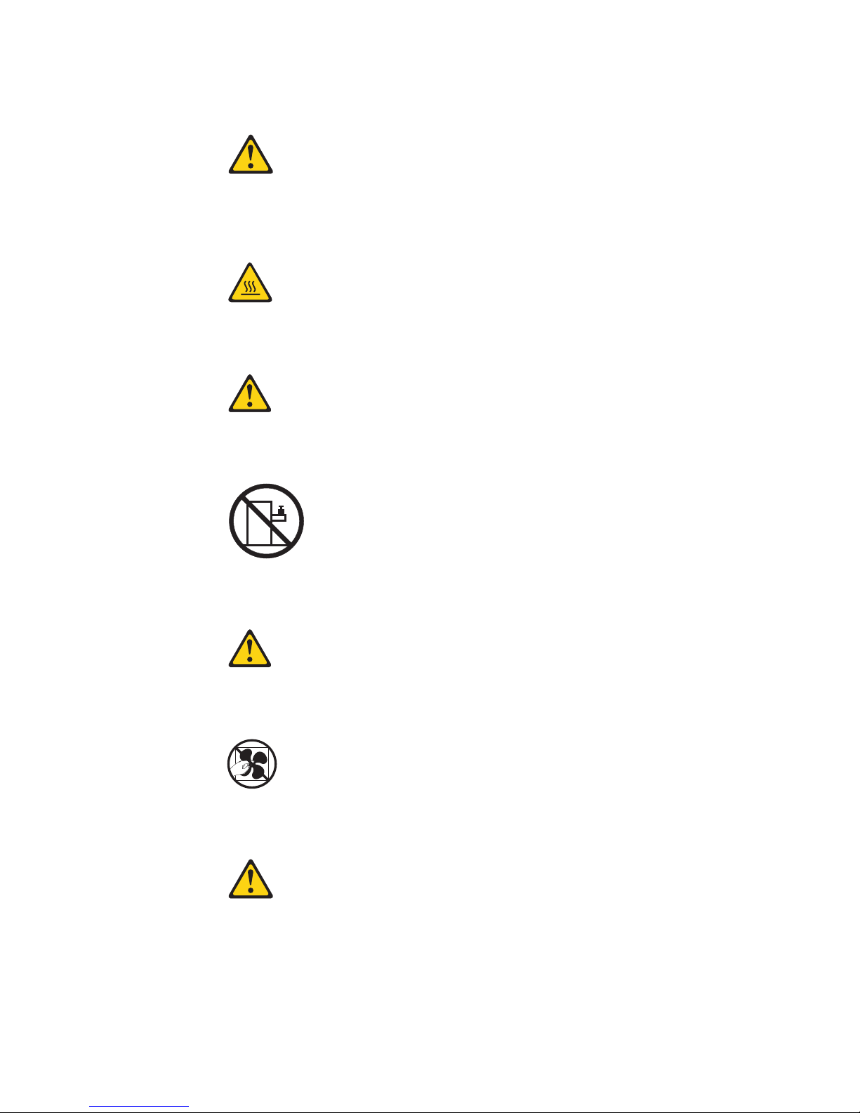
Statement 12
CAUTION:
The following label indicates a hot surface nearby.
Statement 26
CAUTION:
Do not place any object on top of rack-mounted devices.
Statement 27
CAUTION:
Hazardous moving parts are nearby.
Rack Safety Information, Statement 2
xiv System x3550 M4 Type 7914: Installation and Service Guide

DANGER
v Always lower the leveling pads on the rack cabinet.
v Always install stabilizer brackets on the rack cabinet.
v Always install servers and optional devices starting from the bottom of the
rack cabinet.
v Always install the heaviest devices in the bottom of the rack cabinet.
Safety xv

xvi System x3550 M4 Type 7914: Installation and Service Guide

Chapter 1. The System x3550 M4 server
This publication contains information and instructions for setting up your System
x3550 M4 server, instructions for installing some optional devices, cabling and
configuring the server, removing and replacing devices, and diagnostics and
troubleshooting information.
In addition to the instructions in Chapter 2, “Installing optional devices,” on page
25 for installing optional hardware devices, updating firmware and device drivers,
and completing the installation, Business Partners must also complete the steps in
“Instructions for Business Partners” on page 25.
The System x3550 M4 server is a 1-U-high
network transaction processing. This high-performance, multicore server is ideally
suited for networking environments that require superior microprocessor
performance, input/output (I/O) flexibility, and high manageability.
Performance, ease of use, reliability, and expansion capabilities were key
considerations in the design of the server. These design features make it possible
for you to customize the system hardware to meet your needs today and provide
flexible expansion capabilities for the future.
The server comes with a limited warranty. For information about the terms of the
warranty, see the Warranty Information document that comes with the server.
1
rack model server for high-volume
The server contains Lenovo X-Architecture technologies, which help increase
performance and reliability. For more information, see “What your server offers”
on page 10 and “Reliability, availability, and serviceability” on page 14.
You can obtain up-to-date information about the server and other server products
at http://www.ibm.com/systems/x/. At http://www.ibm.com/support/
mysupport/, you can create a personalized support page by identifying products
that are of interest to you. From this personalized page, you can subscribe to
weekly email notifications about new technical documents, search for information
and downloads, and access various administrative services.
If you participate in the client reference program, you can share information about
your use of technology, best practices, and innovative solutions; build a
professional network; and gain visibility for your business. For more information
about the client reference program, see http://www.ibm.com/ibm/
clientreference/.
The hot-swap server models support up to eight 2.5-inch hot-swap hard disk
drives or three 3.5-inch hot-swap hard disk drives. The simple-swap server models
support up to three 3.5-inch simple-swap hard disk drives. It supports 2.5-inch
hot-swap Serial Attached SCSI (SAS) or SATA hard disk drives, 3.5-inch hot-swap
Serial Attached SCSI (SAS) or SATA hard disk drives, or 3.5-inch simple-swap
SATA hard disk drives.
1. Racks are marked in vertical increments of 1.75 inches each. Each increment is referred to as a unit, or a “U”. A 1-U-high device
is approximately 1.75 inches tall.
© Copyright Lenovo 2012, 2015
1

Note: The illustrations in this document might differ slightly from your model.
The following illustration shows the 2.5-inch hot-swap server models with an
optional optical drive bay.
Figure 1. Front view: 2.5-inch model
The following illustration shows the 3.5-inch hot-swap or simple-swap server
models. The servers support up to three 3.5-inch hot-swap SAS/SATA or
simple-swap SATA hard disk drives.
Figure 2. Front view: 3.5-inch model
If firmware and documentation updates are available, you can download them
from the website. The server might have features that are not described in the
documentation that comes with the server, and the documentation might be
updated occasionally to include information about those features, or technical
updates might be available to provide additional information that is not included
in the server documentation. To check for updates, go to http://www.ibm.com/
supportportal/.
Record information about the server in the following table.
Product name System x3550 M4 server
Machine type 7914
Model number _____________________________________________
Serial number _____________________________________________
The model number and serial number are on the ID label on the front of the
server, as shown in the following illustration.
2 System x3550 M4 Type 7914: Installation and Service Guide
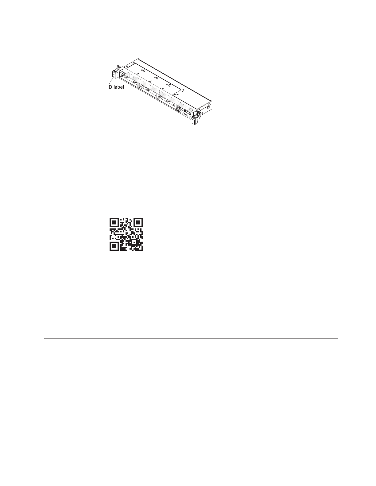
Note: The illustrations in this document might differ slightly from your hardware.
Figure 3. ID label
In addition, the system service label, which is on the cover of the server, provides a
QR code for mobile access to service information. You can scan the QR code using
a QR code reader and scanner with a mobile device and get quick access to the
Service Information website. The Service Information website provides additional
information for parts installation and replacement videos, and error codes for
server support.
The following illustration shows the QR code (http://ibm.co/114FFrw):
Figure 4. QR code
You can download an ServerGuide Setup and Installation CD to help you configure
the hardware, install device drivers, and install the operating system.
For a list of supported optional devices for the server, see http://www.ibm.com/
systems/info/x86servers/serverproven/compat/us/.
See the Rack Installation Instructions document on the System x Documentation CD
for complete rack installation and removal instructions.
The Documentation CD
The Documentation CD contains documentation for the server in Portable Document
Format (PDF) and includes the Documentation Browser to help you find
information quickly.
Hardware and software requirements
The Documentation CD requires the following minimum hardware and software:
v Microsoft Windows XP, Windows 2000, or Red Hat Linux
v 100 MHz microprocessor
v 32 MB of RAM
Chapter 1. The System x3550 M4 server 3

v Adobe Acrobat Reader 3.0 (or later) or xpdf, which comes with Linux operating
systems
Using the Documentation Browser
Use the Documentation Browser to browse the contents of the CD, read brief
descriptions of the documents, and view documents, using Adobe Acrobat Reader
or xpdf.
The Documentation Browser automatically detects the regional settings in use in
your server and displays the documents in the language for that region (if
available). If a document is not available in the language for that region, the
English-language version is displayed.
Use one of the following procedures to start the Documentation Browser:
v If Autostart is enabled, insert the CD into the CD or DVD drive. The
Documentation Browser starts automatically.
v If Autostart is disabled or is not enabled for all users, use one of the following
procedures:
– If you are using a Windows operating system, insert the CD into the CD or
DVD drive and click Start > Run.IntheOpen field, type
e:\win32.bat
where e is the drive letter of the CD or DVD drive, and click OK.
– If you are using Red Hat Linux, insert the CD into the CD or DVD drive;
then, run the following command from the /mnt/cdrom directory:
sh runlinux.sh
Select the server from the Product menu. The Available Topics list displays all the
documents for the server. Some documents might be in folders. A plus sign (+)
indicates each folder or document that has additional documents under it. Click
the plus sign to display the additional documents.
When you select a document, a description of the document is displayed under
Topic Description. To select more than one document, press and hold the Ctrl key
while you select the documents. Click View to view the selected document or
documents in Acrobat Reader or xpdf. If you selected more than one document, all
the selected documents are opened in Acrobat Reader or xpdf.
To search all the documents, type a word or word string in the Search field and
click Search. The documents in which the word or word string appears are listed
in order of the most occurrences. Click a document to view it, and press Crtl+F to
use the Acrobat search function, or press Alt+F to use the xpdf search function
within the document.
Click Help for detailed information about using the Documentation Browser.
Related documentation
This Installation and Service Guide contains general information about the server
including how to set up and cable the server, how to install supported optional
devices, how to configure the server, and information to help you solve problems
yourself and information for service technicians. The following documentation also
comes with the server:
v Environmental Notices and User Guide
4 System x3550 M4 Type 7914: Installation and Service Guide

This document is in PDF format on the Documentation CD. It contains translated
environmental notices.
v License Agreement for Machine Code
This document is in PDF format on the Documentation CD. It provides translated
versions of the License Agreement for Machine Code for your product.
v Important Notices
This document is in printed format and comes with the server. It contains
information about the safety, environmental, and electronic emission notices for
your Lenovo product.
v Licenses and Attributions Documents
This document is in PDF format on the Documentation CD. It provides the open
source notices.
v Rack Installation Instructions
This printed document contains instructions for installing the server in a rack
and comes with the rack kit.
v Rack Safety Information
This multilingual document provides translated versions of the caution and
danger statements that appear in the rack documentation. Each caution and
danger statement has an assigned number, which you can use to locate the
corresponding statement in your native language.
v Safety Information
This document is in PDF format on the Documentation CD. It contains translated
caution and danger statements. Each caution and danger statement that appears
in the documentation has a number that you can use to locate the corresponding
statement in your language in the Safety Information document.
v Safety Information Labels
This document provides the Simplified Chinese, Mongolian, Tibetan, Uygur, and
Zhuang translated versions of the product safety labels.
v Warranty Information
This document is in printed format and comes with the server. It contains
warranty terms and a pointer to the Lenovo Statement of Limited Warranty on
the website.
Depending on the server model, additional documentation might be included on
the Documentation CD.
The ToolsCenter for System x and BladeCenter is an online information center that
contains information about tools for updating, managing, and deploying firmware,
device drivers, and operating systems. The ToolsCenter for System x and
BladeCenter is at http://publib.boulder.ibm.com/infocenter/toolsctr/v1r0/.
The server might have features that are not described in the documentation that
you received with the server. The documentation might be updated occasionally to
include information about those features, or technical updates might be available
to provide additional information that is not included in the server documentation.
These updates are available from the website. To check for updates, go to
http://www.ibm.com/supportportal/.
Chapter 1. The System x3550 M4 server 5

Notices and statements in this document
The caution and danger statements in this document are also in the multilingual
Safety Information document, which is on the System x Documentation CD. Each
statement is numbered for reference to the corresponding statement in your
language in the Safety Information document.
The following notices and statements are used in this document:
v Note: These notices provide important tips, guidance, or advice.
v Important: These notices provide information or advice that might help you
avoid inconvenient or problem situations.
v Attention: These notices indicate potential damage to programs, devices, or data.
An attention notice is placed just before the instruction or situation in which
damage might occur.
v Caution: These statements indicate situations that can be potentially hazardous
to you. A caution statement is placed just before the description of a potentially
hazardous procedure step or situation.
v Danger: These statements indicate situations that can be potentially lethal or
extremely hazardous to you. A danger statement is placed just before the
description of a potentially lethal or extremely hazardous procedure step or
situation.
Server features and specifications
The following information is a summary of the features and specifications of the
server.
Depending on the model, some features might not be available, or some
specifications might not apply.
6 System x3550 M4 Type 7914: Installation and Service Guide

Table 1. Server features and specifications
Microprocessor (depending on the
model):
v Supports up to two multi-core
Memory (depending on the model):
v Minimum: 2 GB
v Maximum: 768 GB
microprocessors (one installed)
v Level-3 cache
v Two QuickPath Interconnect (QPI)
links speed up to 8.0 GT per
second
Notes:
v Type:
v Use the Setup utility program to
determine the type and speed of
the microprocessors.
v For a list of supported
microprocessors, see
http://www.ibm.com/systems/
info/x86servers/serverproven/
compat/us/.
v Slots: 24 dual inline
v Supports (depending on the
– 64 GB using unbuffered DIMMs
(UDIMMs)
– 384 GB using registered DIMMs
(RDIMMs)
– 768 GB using load reduction
DIMMs (LRDIMMs)
– PC3-8500 (DDR3-1066),
PC3-10600 (DDR3-1333),
PC3-12800 (DDR3-1600), or
PC3-14900 (DDR3-1866)
– Single-rank, dual-rank, or
quad-rank
– Registered DIMM (RDIMM),
unbuffered DIMM (UDIMM), or
load reduced DIMM (LRDIMM)
model):
– 4 GB UDIMM
– 2 GB, 4 GB, 8 GB, and 16 GB
RDIMMs
– 32 GB LRDIMM
SATA optical drives (optional for
2.5-inch models):
v DVD-ROM
v Multi-burner
Hard disk drive expansion bays
(depending on the model):
v 2.5-inch models: Up to eight
2.5-inch hot-swap SAS/SATA hard
disk drive bays (with an optional
optical drive bay)
v 3.5-inch models: Up to three
3.5-inch hot-swap SAS/SATA or
simple-swap SATA hard disk drive
bays
Attention:
v As a general consideration, do not
mix standard 512-byte and
advanced 4-KB format drives in
the same RAID array because it
may lead to potential performance
issues.
PCI expansion slots:
Supports two PCI riser slots:
v Slot 1 supports low-profile cards.
– PCI Express 3.0 x16
v Slot 2 supports half-length,
full-height cards.
– PCI Express 3.0 x8
– PCI Express 3.0 x16 (two
microprocessors installed)
– PCI-X 64-bit/133 MHz
Chapter 1. The System x3550 M4 server 7

Table 1. Server features and specifications (continued)
Video controller (integrated into
IMM2):
v Matrox G200eR2
Note: The maximum video
resolution is 1600 x 1200 at 75 Hz.
– SVGA compatible video
controller
– DDR3 528 MHz SDRAM video
memory controller
– Avocent Digital Video
Compression
– 16 MB of video memory (not
expandable)
Hot-swap fans:
v One microprocessor: 4 dual-motor
hot-swap fans.
v Two microprocessors: 6 dual-motor
hot-swap fans.
Power supply:
v Up to two hot-swap power
supplies for redundancy support
– 550-watt ac
– 750-watt ac
– 750-watt dc
Note: Power supplies in the server
must be with the same power rating
or wattage.
Integrated functions:
v Integrated Management Module II
(IMM2), which consolidates
multiple management functions in
a single chip.
v Intel I350AM4 Quad Port Gigabit
Ethernet controller with Wake on
LAN support
v Eight Universal Serial Bus (USB)
ports for 3.5-inch models. Seven
Universal Serial Bus (USB) ports
for 2.5-inch models. One port is for
optional USB flash device with
embedded hypervisor software is
installed.
v Six network ports (four 1 Gb
Ethernet ports on the system board
and two additional ports when the
optional IBM Dual-Port 10 Gb
Network Adapter is installed)
v One System Management 1 Gb
Ethernet port on the rear connected
to a systems management network.
This system management
connector is dedicated to the IMM2
functions.
v One serial port
RAID controllers (depending on the
model):
v A ServeRAID H1110 SAS/SATA
adapter that provides RAID 0, 1,
and 10.
v A ServeRAID M1115 SAS/SATA
adapter that provides RAID 0, 1,
and 10 with optional FoD RAID
5/50 and SED (Self Encrypting
Drive) upgrade.
v A ServeRAID M5110 SAS/SATA
adapter that provides RAID 0, 1,
and 10. Optional upgrade:
– RAID 5/50 (512 MB Cache) with
optional FoD RAID 6/60 and
SED upgrade
– RAID 5/50 (512 MB Flash) with
optional FoD RAID 6/60 and
SED upgrade
– RAID 5/50 (1 GB Flash) with
optional FoD RAID 6/60 and
SED upgrade
– RAID 5/50 and SED (Zero
Cache)
v A ServeRAID M5120 SAS/SATA
adapter that provides RAID 0, 1,
and 10. Optional upgrade:
– RAID 5/50 (512 MB Cache) with
optional FoD RAID 6/60 and
SED upgrade
– RAID 5/50 (512 MB Flash) with
optional FoD RAID 6/60 and
SED upgrade
– RAID 5/50 (1 GB Flash) with
optional FoD RAID 6/60 and
SED upgrade
– RAID 5/50 and SED (Zero
Cache)
8 System x3550 M4 Type 7914: Installation and Service Guide

Table 1. Server features and specifications (continued)
Environment: compliant with
ASHRAE class A3 specifications.
Server on:
v Temperature:
– 5°C to 40°C (41°F to 104°F)
– Altitude: 0 to 950 m (3,117 ft);
decrease the maximum system
temperature by 1°C for every
175-m increase in altitude.
v Maximum altitude: 3,050 m (10,000
ft), 5°C to 28°C (41°F to 82.4°F)
v Humidity:
– Non-condensing: -12°C dew
point (10.4°F)
– Relative humidity: 8% to 85%
v Maximum dew point: 24°C (75.2°F)
v Maximum rate of temperature
change:
– Tape drives: 5°C/hr (41°F/hr)
– Hard disk drives: 20°C/hr
(68°F/hr)
Server off:
v Temperature: 5°C to 45°C (41°F to
113°F)
v Relative humidity: 8% to 85%
v Maximum dew point: 27°C (80.6°F)
Storage (non-operating):
v Temperature: 1°C to 60°C (33.8°F to
140°F)
v Maximum altitude: 3,050 m (10,000
ft)
v Relative humidity: 5% to 80%
v Maximum dew point: 29°C (84.2°F)
Shipment (non-operating):
v Temperature: -40°C to 60°C (-40°F
to 140°F)
v Maximum altitude: 10,700 m
(35,105 ft)
v Relative humidity: 5% to 100%
v Maximum dew point: 29°C (84.2°F)
Particulate contamination: airborne
particulates and reactive gases acting
alone or in combination with other
environmental factors such as
humidity or temperature might pose
a risk to the server. For information
about the limits for particulates and
gases, see “Particulate
contamination” on page 603.
Attention:
v Design to ASHRAE Class A3,
ambient of 40°C, with relaxed
support:
– Support cloud like workload
with no performance
degradation acceptable
(Turbo-Off)
– Under no circumstance, can any
combination of worst case
workload and configuration
result in system shutdown or
design exposure at 40°C
v Specific microprocessors supported
environment:
– Microprocessor Intel Xeon
E5-2690, 135W:
- Temperature: 10°C to 27°C
(50°F to 80.6°F)
- Altitude: 0 to 304.8 m (1,000
ft)
– Microprocessor models with
115W and 130W:
- Temperature: 10°C to 35°C
(50°F to 95°F)
- Altitude: 0 to 914.4 m (3,000
ft)
Size:
v 1U
v Height: 43 mm (1.7 inches)
v Depth: 734 mm (28.9 inches)
v Width: 429 mm (16.9 inches)
v Weight: approximately 16.4 kg
(36.16 lb) when fully configured
Acoustical noise emissions:
v Sound power, idling: 6.5 bels
maximum
v Sound power, operating: 6.5 bels
maximum
Heat output:
Approximate heat output:
v Minimum configuration: 461 Btu
per hour (AC 135 watts)
v Maximum configuration: 3378 Btu
per hour (AC 990 watts)
Electrical input:
v Sine-wave input (50 - 60 Hz)
required
v Input voltage low range:
– Minimum: 100 V ac
– Maximum: 127 V ac
v Input voltage high range:
– Minimum: 200 V ac
– Maximum: 240 V ac
v Input kilovolt-amperes (kVA),
approximately:
– Minimum: 0.14 kVA
– Maximum: 0.993 kVA
Notes:
1. Power consumption and heat
output vary depending on the
number and type of optional
features installed and the
power-management optional
features in use.
2. The noise emission level stated is
the declared (upper limit) sound
power level, in bels, for a random
sample of machines. All
measurements are made in
accordance with ISO 7779 and
reported in conformance with ISO
9296. Actual sound-pressure levels
in a given location might exceed
the average values stated because
of room reflections and other
nearby noise sources. The noise
emission level stated in the
declared (upper limit)
sound-power level, in bels, for a
random sample of system.
EU Regulation 617/2013 Technical Documentation:
International Business Machines Corporation
New Orchard Road
Armonk, New York 10504
Chapter 1. The System x3550 M4 server 9

http://www.ibm.com/customersupport/
For more information on the energy efficiency program, go to
http://www.ibm.com/systems/x/hardware/energy-star/index.html
Product Type:
Computer server
Year first manufactured:
2012
Internal/external power supply efficiency:
v http://www.plugloadsolutions.com/psu_reports/
IBM_FSA011_550W_SO-301_Report.pdf
v http://www.plugloadsolutions.com/psu_reports/IBM_7001676-
XXXX_550W_SO-458_Report.pdf
v http://www.plugloadsolutions.com/psu_reports/IBM_7001605-
XXXX_750W_SO-258_Report.pdf
v http://www.plugloadsolutions.com/psu_reports/SO-299_IBM_DPS-
750AB-1_750W_Report.pdf
v http://www.plugloadsolutions.com/psu_reports/IBM_DPS-750AB-14
%20A_750W_SO-527_Report.pdf
Maximum power (watts):
See Power supply.
Idle state power (watts):
219
Sleep mode power (watts):
Not applicable for servers.
Off mode power (watts):
17
Noise levels (the declared A-weighed sound power level of the computer):
See Acoustical noise emissions.
Test voltage and frequency:
230V/50Hzor60Hz
Total harmonic distortion of the electricity supply system:
The maximum harmonic content of the input voltage waveform will be
equal or less than 2%. The qualification is compliant with EN 61000-3-2.
Information and documentation on the instrumentation set-up and circuits used
for electrical testing:
ENERGY STAR Test Method for Computer Servers; ECOVA Generalized
Test Protocol for Calculating the Energy Efficiency of Internal Ac-Dc and
Dc-Dc Power Supplies.
Measurement methodology used to determine information in this document:
ENERGY STAR Servers Version 2.0 Program Requirements; ECOVA
Generalized Test Protocol for Calculating the Energy Efficiency of Internal
Ac-Dc and Dc-Dc Power Supplies.
What your server offers
This section introduces features and technologies the server uses and provides.
v Active Energy Manager
10 System x3550 M4 Type 7914: Installation and Service Guide

The Active Energy Manager solution is an IBM Systems Director plug-in that
measures and reports server power consumption as it occurs. This enables you
to monitor power consumption in correlation to specific software application
programs and hardware configurations. You can obtain the measurement values
through the systems-management interface and view them, using IBM Systems
Director. For more information, including the required levels of IBM Systems
Director and Active Energy Manager, see the IBM Systems Director Information
Center at http://pic.dhe.ibm.com/infocenter/director/pubs/index.jsp?topic=
%2Fcom.ibm.director.main.helps.doc%2Ffqm0_main.html or see
http://www.ibm.com/systems/management/director/downloads.html.
v Dynamic System Analysis (DSA)
The server comes with the Dynamic System Analysis (DSA) Preboot diagnostic
program. DSA collects and analyzes system information to aid in diagnosing
server problems, as well as offering a rich set of diagnostic tests of the major
components of the server. DSA creates a DSA log, which is a chronologically
ordered merge of the system-event log (as the IPMI event log), the integrated
management module (IMM) event log (as the ASM event log), and the
operating-system event logs. You can send the DSA log as a file to Lenovo
Support or view the information as a text file or HTML file.
Two editions of Dynamic System Analysis are available: DSA Portable and DSA
Preboot. For more information about both editions, see “DSA editions” on page
145.
v Features on Demand
If a Features on Demand feature is integrated in the server or in an optional
device that is installed in the server, you can purchase an activation key to
activate the feature. For information about Features on Demand, see
/http://www.ibm.com/systems/x/fod/.
v ServerGuide Setup and Installation CD
The ServerGuide Setup and Installation CD, which you can download from the
web, provides programs to help you set up the server and install a Windows
operating system. The ServerGuide program detects installed optional hardware
devices and provides the correct configuration programs and device drivers. For
more information about the ServerGuide Setup and Installation CD, see “Using the
ServerGuide Setup and Installation CD” on page 100.
®
v IBM
Systems Director
IBM Systems Director is a platform-management foundation that streamlines the
way you manage physical and virtual systems in a heterogeneous environment.
By using industry standards, IBM Systems Director supports multiple operating
systems and virtualization technologies. For more information, see the IBM
Systems Director Information Center at http://pic.dhe.ibm.com/infocenter/
director/pubs/index.jsp?topic=%2Fcom.ibm.director.main.helps.doc
%2Ffqm0_main.html and “IBM Systems Director” on page 15.
v Integrated Management Module II (IMM2)
The integrated management module II (IMM2) combines service processor
functions, video controller, and remote presence and blue-screen capture features
in a single chip. The IMM provides advanced service-processor control,
monitoring, and alerting function. If an environmental condition exceeds a
threshold or if a system component fails, the IMM lights LEDs to help you
diagnose the problem, records the error in the IMM event log, and alerts you to
the problem. Optionally, the IMM also provides a virtual presence capability for
remote server management capabilities. The IMM provides remote server
management through the following industry-standard interfaces:
– Intelligent Platform Management Interface (IPMI) version 2.0
Chapter 1. The System x3550 M4 server 11

– Simple Network Management Protocol (SNMP) version 3.0
– Common Information Model (CIM)
– Web browser
Some of the features that are unique to the IMM are enhanced performance,
higher-resolution remote video, expanded security options, and Feature on
Demand enablement for hardware and firmware options.
For additional information, see “Using the integrated management module” on
page 109 and the Integrated Management Module II User’s Guide at
http://www.ibm.com/support/entry/portal/docdisplay?lndocid=MIGR-
5086346.
v Integrated network support
The server comes with an integrated dual-port Intel Gigabit Ethernet controller,
which supports connection to a 10 Mbps, 100 Mbps, or 1000 Mbps network. For
more information, see “Configuring the Ethernet controller” on page 113.
v Integrated Trusted Platform Module (TPM)
This integrated security chip performs cryptographic functions and stores
private and public secure keys. It provides the hardware support for the Trusted
Computing Group (TCG) specification. You can download the software to
support the TCG specification, when the software is available. You can enable
TPM support through the Setup utility under the System Security menu option.
v Large data-storage capacity and hot-swap capability
The hot-swap server models support a maximum of eight 2.5-inch or three
3.5-inch hot-swap Serial Attached SCSI (SAS) hard disk drives or hot-swap Serial
ATA (SATA) hard disk drives. The simple-swap server models support a
maximum of three 3.5-inch simple-swap SATA hard disk drives.
With the hot-swap feature, you can add, remove, or replace hard disk drives
without turning off the server.
v Large system-memory capacity
The server can support up to 768 GB of system memory. The server provides 24
dual inline memory module (DIMM) connectors. The server memory controller
supports error correcting code (ECC) for PC3-8500 (DDR3-1066), PC3-10600
(DDR3-1333), PC3-12800 (DDR3-1600), or PC3-14900 (DDR3-1866), DDR3
(third-generation double-data-rate), synchronous dynamic random access
memory (SDRAM) DIMMs.
v Light path diagnostics
Light path diagnostics provides LEDs to help you diagnose problems. For more
information about light path diagnostics and the LEDs, see “Light path
diagnostics” on page 130 and “Light path diagnostics LEDs” on page 132.
v Mobile access to Service Information website
The server provides a QR code on the system service label, which is on the
cover of the server, that you can scan using a QR code reader and scanner with
a mobile device to get quick access to the Service Information website. The
Service Information website provides additional information for parts
installation and replacement videos, and error codes for server support. For the
QR code, see QR code information on page Chapter 1, “The System x3550 M4
server,” on page 1.
v Multi-core processing
The server supports up to two multi-core microprocessors. The server comes
with a minimum of one microprocessor.
v PCI adapter capabilities
12 System x3550 M4 Type 7914: Installation and Service Guide
 Loading...