

Page 1

LenovoSystemx3250M6
InstallationandServiceGuide
MachineTypes:3633and3943
Page 2

Note
Beforeusingthisinformationandtheproductitsupports,readthegeneralinformationinAppendixD
“Gettinghelpandtechnicalassistance”onpage659,AppendixE“Notices”onpage663,thesafety
information,warranties,andlicensesinformationontheLenovoWebsiteat:
https://support.lenovo.com/documents/LNVO-DOCS
SecondEdition(September2016)
©CopyrightLenovo2016.
LIMITEDANDRESTRICTEDRIGHTSNOTICE:IfdataorsoftwareisdeliveredpursuanttoaGeneralServices
Administration“GSA”contract,use,reproduction,ordisclosureissubjecttorestrictionssetforthinContractNo.
GS-35F-05925.
Page 3

Contents
Safety..................v
Safetystatements..............vi
Chapter1.Documentationandnotice
types...................1
Relateddocumentation............1
Noticesinthisdocument...........1
Chapter2.AbouttheLenovoSystem
x3250M6server.............3
Serverfeaturesandspecifications........4
Whatyourserveroffers............7
Reliability,Availability,andServiceability....10
Turningonorturningofftheserver.......11
Turningontheserver..........11
Turningofftheserver..........11
Chapter3.Componentlocations...13
Frontview................13
Rearview.................15
Operatorinformationpanel..........16
Servercomponents.............17
System-boardconnectors..........19
System-boardswitchesandjumpers......20
System-boardLEDs............22
Chapter4.Configuration
information..............23
Updatingthefirmware............23
Configuringtheserver............24
UsingtheServerGuideSetupandInstallation
CD.................25
UsingtheSetupUtilityprogram......26
UsingtheBootManagerprogram.....32
Startingthebackupserverfirmware....32
UpdateXpressSystemPackInstaller....32
ChangingthePowerPolicyoptiontothe
defaultsettingsafterloadingUEFIdefaults..32
UsingtheIntegratedManagementModuleII
(IMM2)................33
Usingtheremotepresenceandblue-screen
capturefeatures............34
Usingtheembeddedhypervisor......35
Ethernetcontrollerinformation.......36
EnablingFeaturesonDemandEthernetand
DemandRAIDsoftware.........36
AccessingRAIDconfigurationutility....36
LenovoT oolsCenterSuiteCLIprogram...37
UsingLenovoXClarityAdministrator....37
UpdatingtheUniversalUniqueIdentifier
(UUID)................38
UpdatingtheDMI/SMBIOSdata......40
ConfiguringonboardSATAsoftwareRAID....42
EnablingtheonboardSATARAID
functionality..............42
CreatingRAIDvolumes.........42
DeletingRAIDvolumes.........43
Markingdisksasspare.........43
Chapter5.Troubleshooting......45
Starthere.................45
Diagnosingaproblem..........45
Openinganonlineservicerequest.....47
Servicebulletins..............47
Checkoutprocedure............48
Precautionsbeforeperformingthecheckout
procedure...............48
Performingthecheckoutprocedure....48
Diagnostictools..............49
Lightpathdiagnostics..........51
ErrorLEDs..............51
Power-supplyLEDs...........52
SystempulseLEDs...........53
Eventlogs...............54
POST................56
DynamicSystemAnalysis........56
Automatedservicerequest(callhome).....58
ElectronicServiceAgent.........58
Errormessages..............59
Troubleshootingbysymptom.........59
Generalproblems............59
Opticaldriveproblems..........60
Harddiskdriveproblems.........60
Hypervisorproblems..........62
Intermittentproblems..........62
Keyboard,mouse,orUSB-deviceproblems.63
Memoryproblems...........63
Monitorproblems............64
Networkconnectionproblems.......66
Optional-deviceproblems........66
Operatingsystembootproblem......66
Powerproblems............67
Serialportproblems...........68
ServerGuideproblems..........68
Softwareproblems...........69
©CopyrightLenovo2016
i
Page 4

USBconnectorproblems.........69
Solvingpowerproblems...........69
SolvingEthernetcontrollerproblems......70
Solvingundeterminedproblems........70
Problemdeterminationtips..........71
Recoveringtheserverfirmware(UEFIupdate
failure)..................72
In-bandmanualrecoverymethod.....73
In-bandautomatedbootrecoverymethod..73
Out-of-bandmethod..........74
Automatedbootrecovery(ABR)........74
Nx-bootfailure...............74
Chapter6.Partslisting,Lenovo
Systemx3250M6...........75
Replaceableservercomponents........75
Structuralparts.............81
Powercords...............82
Chapter7.Removingandinstalling
servercomponents..........85
Beforeremovingorinstallingservercomponents.85
Systemreliabilityguidelines........85
Workinginsidetheserverwiththepoweron.85
Handlingstatic-sensitivedevices.....86
Removingandinstallingservercomponents...86
Removingandinstallingstructuralparts...86
RemovingandinstallingTier1CRUs....94
RemovingandinstallingTier2CRUs....143
Internalcablerouting..........156
Completingthepartsreplacement.....170
InstructionsforBusinessPartners.....171
SendingDSAdatatoLenovo.......171
Returningadeviceorcomponent.....172
AppendixA.IntegratedManagement
ModuleII(IMM2)errormessages.173
IMMEventsthatautomaticallynotifySupport..174
ListofIMMevents.............177
AppendixB.UEFI(POST)error
codes................489
ListofUEFIevents.............489
AppendixC.DSAdiagnostictest
results................501
DSABroadcomnetworktestresults......501
TestresultsfortheDSABroadcomnetwork
test.................501
DSABrocadetestresults..........511
TestresultsfortheDSABrocadetest....511
DSAcheckpointpaneltestresults.......520
TestresultsfortheDSAcheckpointpanel
test.................520
DSACPUstresstestresults.........522
TestresultsfortheDSACPUstresstest...522
DSAEmulexadaptertestresults........525
TestresultsfortheDSAEmulexadapter
test.................525
DSAEXAportpingtestresults........529
TestresultsfortheDSAEXAportpingtest..529
DSAharddrivetestresults..........532
TestresultsfortheDSAharddrivetest...532
DSAIntelnetworktestresults.........533
TestresultsfortheDSAIntelnetworktest..533
DSALSIharddrivetestresults........540
TestresultsfortheDSALSIharddrivetest..540
DSAMellanoxadaptertestresults.......541
TestresultsfortheDSAMellanoxadapter
test.................542
DSAmemoryisolationtestresults.......544
TestresultsfortheDSAmemoryisolation
test.................544
DSAmemorystresstestresults........622
TestresultsfortheDSAmemorystresstest..622
DSANvidiaGPUtestresults.........625
TestresultsfortheDSANvidiaGPUtest...626
DSAopticaldrivetestresults.........632
TestresultsfortheDSAopticaldrivetest..632
DSAsystemmanagementtestresults.....637
TestresultsfortheDSAsystemmanagement
test.................637
DSAtapedrivetestresults..........653
TestresultsfortheDSAtapedrivetest...653
AppendixD.Gettinghelpand
technicalassistance........659
Beforeyoucall...............659
Usingthedocumentation..........660
GettinghelpandinformationfromtheWorldWide
Web...................660
HowtosendDSAdata...........660
Creatingapersonalizedsupportwebpage...660
Softwareserviceandsupport.........661
Hardwareserviceandsupport........661
Taiwanproductservice...........661
AppendixE.Notices.........663
Trademarks................664
Importantnotes..............664
Recyclinginformation............665
Particulatecontamination..........665
Telecommunicationregulatorystatement....665
Electronicemissionnotices..........666
iiLenovoSystemx3250M6InstallationandServiceGuide
Page 5

FederalCommunicationsCommission(FCC)
statement...............666
IndustryCanadaClassAemissioncompliance
statement...............666
Avisdeconformitéàlaréglementation
d'IndustrieCanada...........666
AustraliaandNewZealandClassA
statement...............666
EuropeanUnionEMCDirectiveconformance
statement...............666
GermanyClassAstatement.......667
Japaneseelectromagneticcompatibility
statements..............668
KoreaCommunicationsCommission(KCC)
statement...............668
RussiaElectromagneticInterference(EMI)
ClassAstatement...........669
People'sRepublicofChinaClassAelectronic
emissionstatement...........669
TaiwanClassAcompliancestatement...669
TaiwanBSMIRoHSdeclaration......670
Index.................671
©CopyrightLenovo2016
iii
Page 6

ivLenovoSystemx3250M6InstallationandServiceGuide
Page 7
Safety
Beforeinstallingthisproduct,readtheSafetyInformation.
Antesdeinstalaresteproduto,leiaasInformaçõesdeSegurança.
Læssikkerhedsforskrifterne,førduinstallererdetteprodukt.
Leesvoordatuditproductinstalleerteerstdeveiligheidsvoorschriften.
Ennenkuinasennattämäntuotteen,lueturvaohjeetkohdastaSafetyInformation.
Avantd'installerceproduit,lisezlesconsignesdesécurité.
VorderInstallationdiesesProduktsdieSicherheitshinweiselesen.
Primadiinstallarequestoprodotto,leggereleInformazionisullaSicurezza.
Lessikkerhetsinformasjonen(SafetyInformation)førduinstallererdetteproduktet.
Antesdeinstalaresteproduto,leiaasInformaçõessobreSegurança.
©CopyrightLenovo2016
v
Page 8
Antesdeinstalaresteproducto,lealainformacióndeseguridad.
Lässäkerhetsinformationeninnanduinstallerardenhärprodukten.
Safetystatements
Thesestatementsprovidethecautionanddangerinformationthatisusedinthisdocumentation.
Important:Eachcautionanddangerstatementinthisdocumentationislabeledwithanumber.Thisnumber
isusedtocrossreferenceanEnglish-languagecautionordangerstatementwithtranslatedversionsofthe
cautionordangerstatementintheSafetyInformationdocument.
Forexample,ifacautionstatementislabeledStatement1,translationsforthatcautionstatementareinthe
SafetyInformationdocumentunderStatement1.
Besuretoreadallcautionanddangerstatementsinthisdocumentationbeforeyouperformtheprocedures.
Readanyadditionalsafetyinformationthatcomeswithyoursystemoroptionaldevicebeforeyouinstall
thedevice.
viLenovoSystemx3250M6InstallationandServiceGuide
Page 9
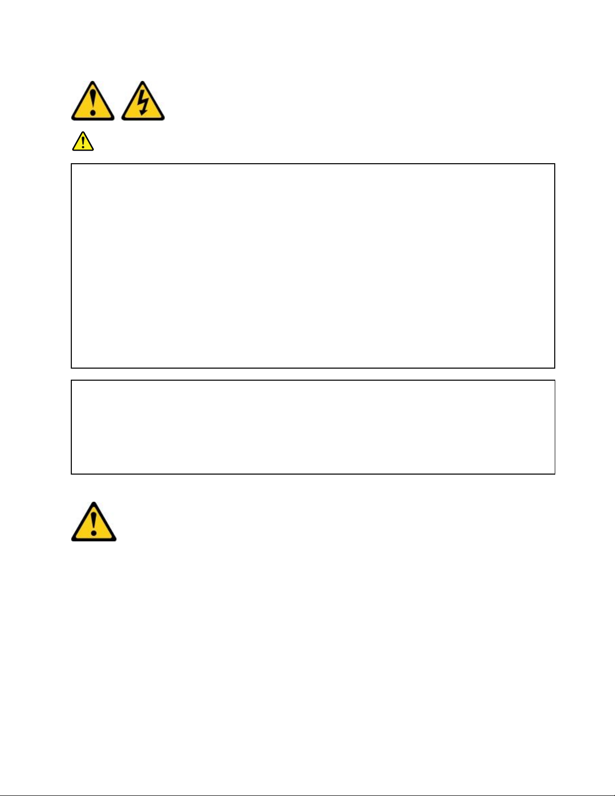
Statement1
DANGER
Electricalcurrentfrompower,telephone,andcommunicationcablesishazardous.
Toavoidashockhazard:
•Donotconnectordisconnectanycablesorperforminstallation,maintenance,orreconfiguration
ofthisproductduringanelectricalstorm.
•Connectallpowercordstoaproperlywiredandgroundedelectricaloutlet.
•Connecttoproperlywiredoutletsanyequipmentthatwillbeattachedtothisproduct.
•Whenpossible,useonehandonlytoconnectordisconnectsignalcables.
•Neverturnonanyequipmentwhenthereisevidenceoffire,water,orstructuraldamage.
•Disconnecttheattachedpowercords,telecommunicationssystems,networks,andmodems
beforeyouopenthedevicecovers,unlessinstructedotherwiseintheinstallationand
configurationprocedures.
•Connectanddisconnectcablesasdescribedinthefollowingtablewheninstalling,moving,or
openingcoversonthisproductorattacheddevices.
ToConnect:ToDisconnect:
1.TurneverythingOFF.
2.First,attachallcablestodevices.
3.Attachsignalcablestoconnectors.
4.Attachpowercordstooutlet.
5.TurndeviceON.
1.TurneverythingOFF.
2.First,removepowercordsfromoutlet.
3.Removesignalcablesfromconnectors.
4.Removeallcablesfromdevices.
Statement2
CAUTION:
Whenreplacingthelithiumbattery,useonlyPartNumber33F8354oranequivalenttypebattery
recommendedbythemanufacturer .Ifyoursystemhasamodulecontainingalithiumbattery,replace
itonlywiththesamemoduletypemadebythesamemanufacturer.Thebatterycontainslithiumand
canexplodeifnotproperlyused,handled,ordisposedof.Donot:
•Throworimmerseintowater
•Heattomorethan100°C(212°F)
•Repairordisassemble
Disposeofthebatteryasrequiredbylocalordinancesorregulations.
©CopyrightLenovo2016
vii
Page 10
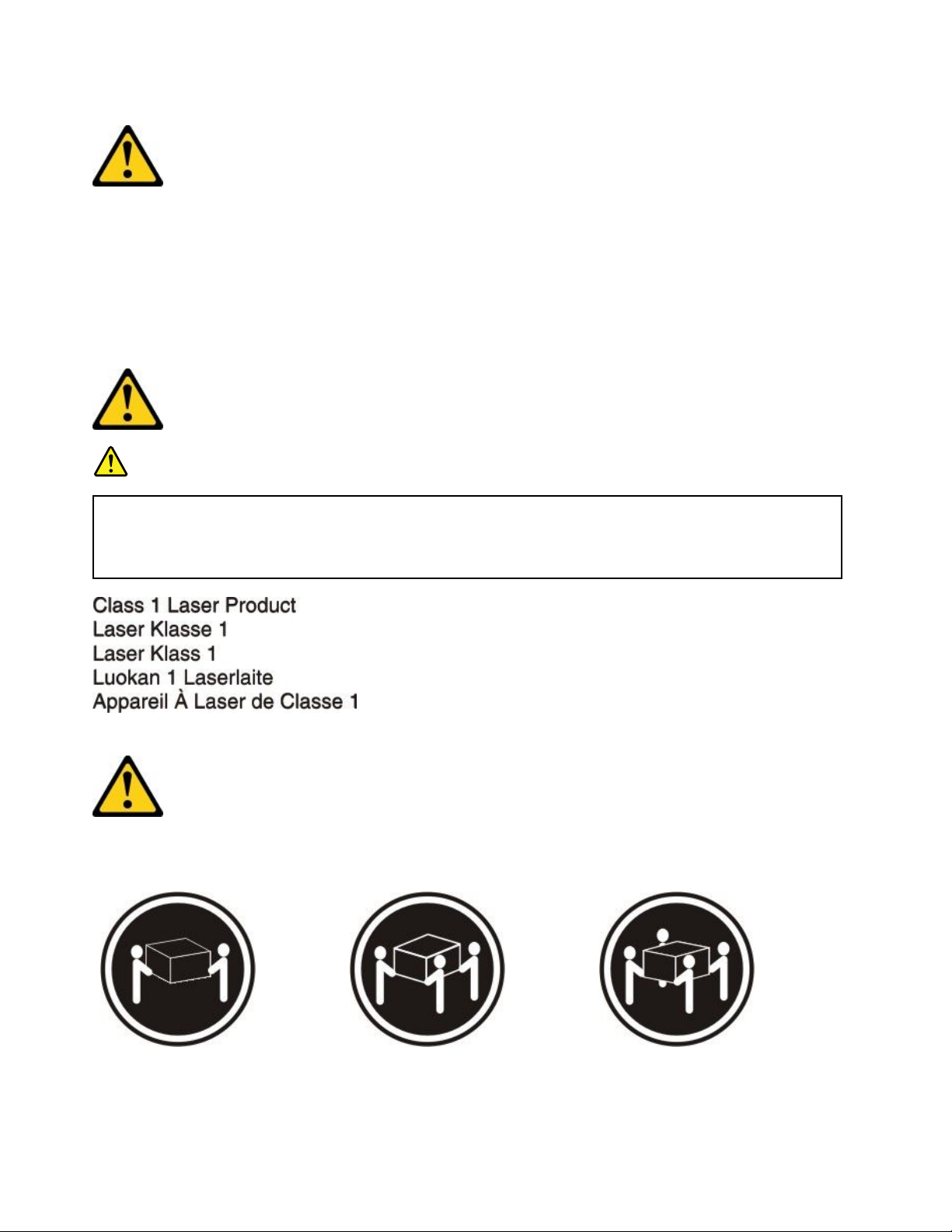
Statement3
CAUTION:
Whenlaserproducts(suchasCD-ROMs,DVDdrives,fiberopticdevices,ortransmitters)are
installed,notethefollowing:
•Donotremovethecovers.Removingthecoversofthelaserproductcouldresultinexposureto
hazardouslaserradiation.Therearenoserviceablepartsinsidethedevice.
•Useofcontrolsoradjustmentsorperformanceofproceduresotherthanthosespecifiedherein
mightresultinhazardousradiationexposure.
DANGER
SomelaserproductscontainanembeddedClass3AorClass3Blaserdiode.Notethefollowing.
Laserradiationwhenopen.Donotstareintothebeam,donotviewdirectlywithoptical
instruments,andavoiddirectexposuretothebeam.
Statement4
CAUTION:Usesafepracticeswhenlifting.
≥18kg(39.7lb)≥32kg(70.5lb)≥55kg(121.2lb)
viiiLenovoSystemx3250M6InstallationandServiceGuide
Page 11
Statement5
CAUTION:
Thepowercontrolbuttononthedeviceandthepowerswitchonthepowersupplydonotturnoff
theelectricalcurrentsuppliedtothedevice.Thedevicealsomighthavemorethanonepower
cord.Toremoveallelectricalcurrentfromthedevice,ensurethatallpowercordsaredisconnected
fromthepowersource.
Statement6
CAUTION:
Ifyouinstallastrain-reliefbracketoptionovertheendofthepowercordthatisconnectedtothe
device,youmustconnecttheotherendofthepowercordtoaneasilyaccessiblepowersource.
Statement8
CAUTION:
Neverremovethecoveronapowersupplyoranypartthathasthefollowinglabelattached.
Hazardousvoltage,current,andenergylevelsarepresentinsideanycomponentthathasthislabel
attached.Therearenoserviceablepartsinsidethesecomponents.Ifyoususpectaproblemwith
oneoftheseparts,contactaservicetechnician.
©CopyrightLenovo2016
ix
Page 12
Statement12
CAUTION:
Thefollowinglabelindicatesahotsurfacenearby.
Statement26
CAUTION:
Donotplaceanyobjectontopofrack-mounteddevices.
Statement27
CAUTION:
Hazardousmovingpartsarenearby.
xLenovoSystemx3250M6InstallationandServiceGuide
Page 13
RackSafetyInformation,Statement2
DANGER
•Alwayslowerthelevelingpadsontherackcabinet.
•Alwaysinstallstabilizerbracketsontherackcabinet.
•Alwaysinstallserversandoptionaldevicesstartingfromthebottomoftherackcabinet.
•Alwaysinstalltheheaviestdevicesinthebottomoftherackcabinet.
©CopyrightLenovo2016
xi
Page 14

xiiLenovoSystemx3250M6InstallationandServiceGuide
Page 15

Chapter1.Documentationandnoticetypes
Thistopicprovidesgeneraldescriptionsofthevariousdocumentationandnoticesforyourserverand
instructionsonhowtoobtainallthedocumentation.
Relateddocumentation
Refertothedocumentationinthistopictohelpyouuseandmaintainyourserver.
ThisInstallationandServiceGuidecontainsgeneralinformationabouttheserverincludinghowtosetupand
cabletheserver,howtoinstallsupportedoptionaldevices,howtoconfiguretheserver,andinformationto
helpyousolveproblemsyourselfandinformationforservicetechnicians.Themostrecentversionofthe
InstallationandServiceGuideisalwaysavailableat:
http://publib.boulder.ibm.com/infocenter/systemx/documentation/index.jsp
Forsafetyinformation,warranties,licenses,andproductdocumentation,goto:
https://support.lenovo.com/documents/LNVO-DOCS
Forwarrantylookup(type,duration,status),goto:
http://www.lenovo.com/warranty
TheT oolsCenterforSystemxandBladeCenterisanonlineinformationcenterthatcontainsinformation
abouttoolsforupdating,managing,anddeployingfirmware,devicedrivers,andoperatingsystems.The
ToolsCenterforSystemxandBladeCenterisathttp://publib.boulder.ibm.com/infocenter/toolsctr/v1r0/.
Theservermighthavefeaturesthatarenotdescribedinthedocumentationthatyoureceivedwiththe
server.Thedocumentationmightbeupdatedoccasionallytoincludeinformationaboutthosefeatures,or
technicalupdatesmightbeavailabletoprovideadditionalinformationthatisnotincludedintheserver
documentation.TheseupdatesareavailablefromtheLenovowebsite.Tocheckforupdates,goto
http://www.lenovo.com/support.
Noticesinthisdocument
ThecautionanddangerstatementsinthisdocumentarealsointhemultilingualSafetyInformation
document,whichisavailableathttps://support.lenovo.com/documents/LNVO-DOCS.Eachstatementis
numberedforreferencetothecorrespondingstatementinyourlanguageintheSafetyInformationdocument.
Thefollowingnoticesandnoticesareusedinthisdocument:
•Note:Thesenoticesprovideimportanttips,guidance,oradvice.
•Important:Thesenoticesprovideinformationoradvicethatmighthelpyouavoidinconvenientor
problemsituations.
•Attention:Thesenoticesindicatepotentialdamagetoprograms,devices,ordata.Anattentionnoticeis
placedjustbeforetheinstructionorsituationinwhichdamagemightoccur.
•CAUTION:Thesenoticesindicatesituationsthatcanbepotentiallyhazardoustoyou.Acautionnoticeis
placedjustbeforethedescriptionofapotentiallyhazardousprocedure,step,orsituation.
•DANGER:Thesenoticesindicatesituationsthatcanbepotentiallylethalorextremelyhazardousto
you.Adangernoticeisplacedjustbeforethedescriptionofapotentiallylethalorextremelyhazardous
procedure,step,orsituation.
©CopyrightLenovo2016
1
Page 16

2LenovoSystemx3250M6InstallationandServiceGuide
Page 17
Chapter2.AbouttheLenovoSystemx3250M6server
Thischapterprovidesasummaryofserverfeatures,technologiestheserveroffers,andinstructionson
turningonandturningofftheserver.
Generalinformation
TheLenovoSystemx3250M6serverisa1-U
processing.Thishigh-performance,multi-coreserverisideallysuitedfornetworkingenvironmentsthat
requiresuperiormicroprocessorperformance,input/output(I/O)flexibility,andhighmanageability.
Thehot-swapservermodelssupportuptoeight2.5-inchhot-swapharddiskdrivesorfour3.5-inch
hot-swapharddiskdrives.Thesimple-swapservermodelssupportuptoeight2.5-inchsimple-swap
harddiskdrivesorfour3.5-inchsimple-swapharddiskdrives.TheLenovoSystemx3250M6server
supports2.5-inchhot-swaporsimple-swapSerialAttachedSCSI(SAS)orSATAharddiskdrives,or3.5-inch
hot-swapSASorSATAharddiskdrives,or3.5-inchsimple-swapSATAharddiskdrives.
Foralistofsupportedoptionaldevicesfortheserver,goto:
http://www.lenovo.com/serverproven/
Recordinformationabouttheserverinthefollowingtable.
Table1.Recordofthesysteminformation
ProductnameMachinetypesModelnumberSerialnumber
LenovoSystemx3250M6
server
Type3633and3943
1
-highrackmodelserverforhigh-volumenetworktransaction
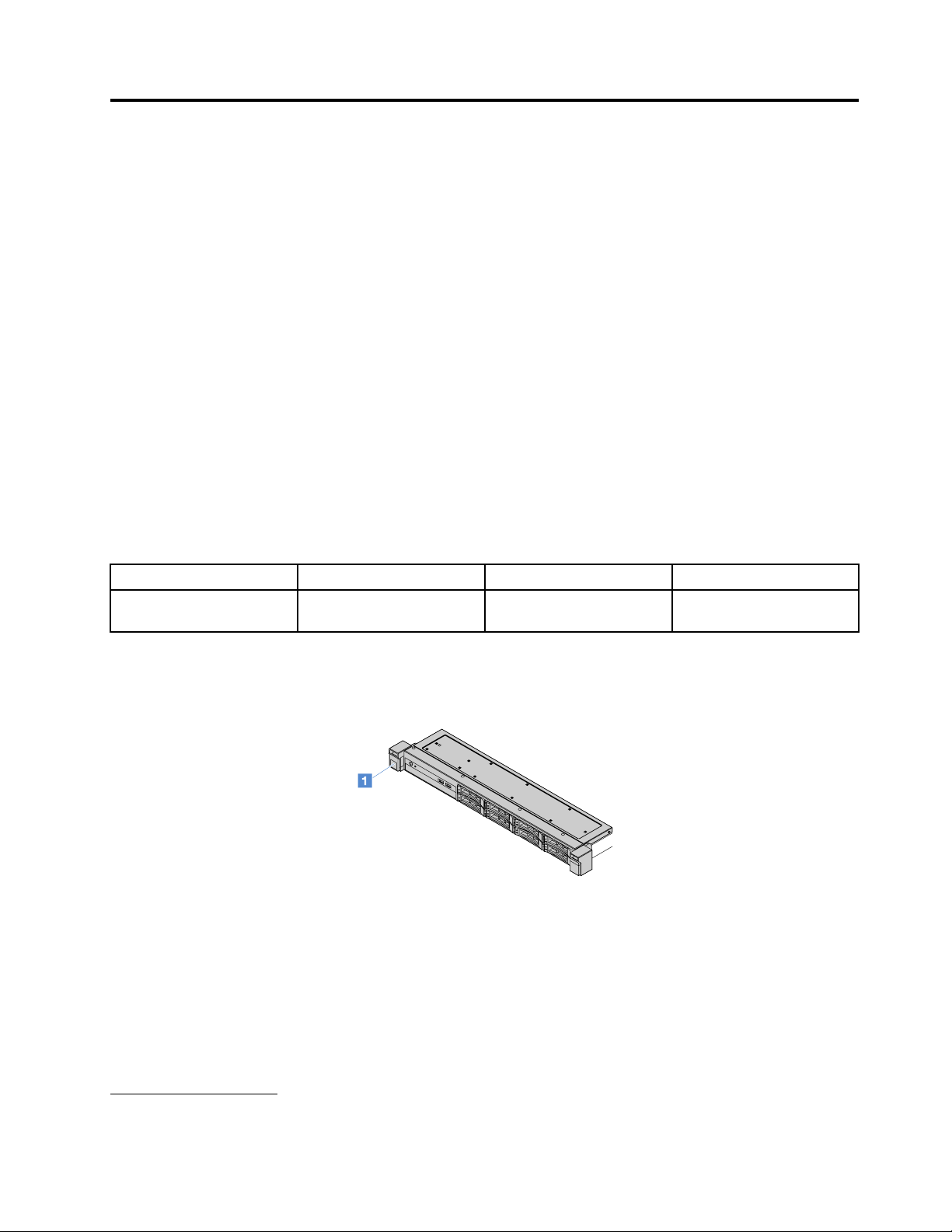
ThemodelnumberandserialnumberareontheIDlabelontherackreleaselatchoftheserver,asshownin
thefollowingillustration.
Figure1.IDlabelonthefrontoftheserver
Performance,easeofuse,reliability,andexpansioncapabilitieswerekeyconsiderationsinthedesignof
theserver.Thesedesignfeaturesmakeitpossibleforyoutocustomizethesystemhardwaretomeetyour
needstodayandprovideflexibleexpansioncapabilitiesforthefuture.
BusinessPartnersmustalsocompletethestepsin“InstructionsforBusinessPartners”onpage171
1.Racksaremeasuredinverticalincrementsof4.45cm(1.75inches)each.Eachincrementiscalleda"U."A1-U-high
deviceis1.75inchestall
.
©CopyrightLenovo2016
3
Page 18

Warrantyandserviceinformation
Theservercomeswithalimitedwarranty.Forinformationaboutthetermsofthewarrantyandgettingservice
andassistance,seetheLenovoWarrantyInformationdocumentthatcomeswiththeserver.
Thesystemservicelabel,whichisonthecoveroftheserver,providesaQRcodeformobileaccesstoservice
information.YoucanscantheQRcodeusingaQRcodereaderandscannerwithamobiledeviceandget
quickaccesstotheLenovoServiceInformationWebsite.TheLenovoServiceInformationWebsiteprovides
additionalinformationforpartsinstallationandreplacementvideos,anderrorcodesforserversupport.
Iffirmwareanddocumentationupdatesareavailable,youcandownloadthemfromtheLenovoWebsite.
Theservermighthavefeaturesthatarenotdescribedinthedocumentationthatcomeswiththeserver,and
thedocumentationmightbeupdatedoccasionallytoincludeinformationaboutthosefeatures,ortechnical
updatesmightbeavailabletoprovideadditionalinformationthatisnotincludedintheserverdocumentation.
Tocheckforupdates,gotohttp://www.lenovo.com/support.
Youcanobtainup-to-dateinformationabouttheserverandotherLenovoserverproductsat
http://shop.lenovo.com/us/en/systems/.Athttp://www.lenovo.com/support,youcancreateapersonalized
supportpagebyidentifyingLenovoproductsthatareofinteresttoyou.Fromthispersonalizedpage,you
cansubscribetoweeklyemailnotificationsaboutnewtechnicaldocuments,searchforinformationand
downloads,andaccessvariousadministrativeservices.
Technologiesandsoftwareinformation
TheservercontainsX-Architecturenextgenerationtechnologies,whichhelpincreaseperformanceand
reliability.Formoreinformation,see“Whatyourserveroffers”onpage7and“Reliability,Availability,and
Serviceability”onpage10.
IfyouparticipateintheLenovoclientreferenceprogram,youcanshareinformationaboutyour
useoftechnology,bestpractices,andinnovativesolutions;buildaprofessionalnetwork;andgain
visibilityforyourbusiness.FormoreinformationabouttheLenovoclientreferenceprogram,goto
http://www.ibm.com/ibm/clientreference/.
Serverfeaturesandspecifications
Thefollowinginformationisasummaryoftheserverfeaturesandspecifications.Dependingonthemodel,
somefeaturesmightnotbeavailable,orsomespecificationsmightvary.
Microprocessor(dependingonthemodel):
•OneIntel
®
quad-core(Xeon
series)microprocessor
•Multi-chippackagemicroprocessorarchitecture
•DesignedforLandGridArray(LGA)1151socket
•Scalableuptofourcores
•SupportIntelFlexMemoryTechnology
Forthespecifictypeandspeedoftheservermicroprocessor,viewtheinformationintheSetupUtility
program.See“UsingtheSetupUtilityprogram”onpage26
Foralistofsupportedmicroprocessors,goto:
http://www.lenovo.com/serverproven/
®
E3-1200v5series)ordual-core(Pentium
®
series,Celeron
®
.
,orCore
™
i3
Memory:
•Minimum:4GB
4LenovoSystemx3250M6InstallationandServiceGuide
Page 19

•Maximum:64GB
•Types:PC4-17000(dual-rank),2133MHz,errorcorrectingcode(ECC),double-data-rate4(DDR4)
unbuffereddualinlinememorymodules(DIMMs)only
•Slots:fourDIMMslots,two-wayinterleaved
Note:Whena4GBormoreofmemory(physicalorlogical)isinstalled,partofthememoryisreserved
forvarioussystemresourcesandisunavailabletotheoperatingsystem.Theamountofmemorythat
isreservedforsystemresourcesdependsontheoperatingsystem,theserverconfiguration,and
theconfiguredPCIoptions.
Opticaldrive:
•UltraSlimDVD-ROMcombo
•Multi-burner
Harddiskdriveexpansionbays(dependingonthemodel):
•Four2.5-inchhot-swapSAS/SATAharddiskdrivebays
•Four2.5-inchsimple-swapSAS/SATAharddiskdrivebays
•Eight2.5-inchhot-swapSAS/SATAharddiskdrivebays
•Eight2.5-inchsimple-swapSAS/SATAharddiskdrivebays
•Four3.5-inchhot-swapSAS/SATAharddiskdrivebays
•Four3.5-inchsimple-swapSATAharddiskdrivebays
Attention:Asageneralconsideration,donotmixstandard512byteandadvanced4KBformatdrives
inthesameRedundantArrayofIndependentDisks(RAID)arraybecausedoingsomightleadto
potentialperformanceissues.
PeripheralComponentInterconnect(PCI)Expressexpansionslots:
TheserversupportstwoPCIeriserslotsontherisercard:
•Slot1:dedicatedtotheServeRAIDM1210SAS/SATAcontroller
•Slot2:supportsonePCIExpressGen3x8half-length,full-heightadapter
Powersupply(dependingonthemodel):
•Onefixed300-wattpowersupply
•Oneortwo460-wattpowersupplies(hot-swapwhentwoinstalled)
RAIDcontroller:
ServeRAIDC110capabilitiesthatsupportRAIDlevels0,1,5,and10
Integratedfunctions:
•IntegratedManagementModuleII(IMM2),whichconsolidatesmultiplemanagementfunctionsina
singlechip
•Inteli350-AM2GigabitEthernetcontrollerandWakeonLANsupport
•UniversalSerialBus(USB):
–TwoUSB3.0connectorsonthefront
Note:DuetothelimitationofUSB3.0connectors,thefrontUSBconnectorsarenotusable
fortheVMwareESXi5.5hypervisor.
–TwoUSB3.0connectorsontherear
Chapter2.AbouttheLenovoSystemx3250M6server5
Page 20

–OneUSB3.0internalconnectoronthesystemboardfortheUSBhypervisorkey
•Four-portintegratedSATAcontroller
•One-portintegratedSATAportfortheopticaldrive(optional)
•Oneserialportheader(functionalwithSerialPortUpgradeKitinstalled)
•Onevideographicsarray(VGA)connectorontherear
Videocontroller(integratedintoIMM2):
•MatroxG200eR2
•SVGAcompatiblevideocontroller
•AAVICAhardwarevideocompression
•Videomemorynotexpandable
•Maximumvideoresolution:1600x1200at75Hz
Size:
•1U
•Height:43mm(1.69inches)
•Depth:576mm(22.68inches)
•Width:
–WithoutElectronicIndustriesAssociation(EIA)brackets:434.6mm(17.11inches)
–WithEIAbrackets:482mm(18.98inches)
•Maximumweight:13.8kg(30.36lb)
Acousticalnoiseemissions:
Soundpower:5.4belsforbothidleandoperatingenvironment
Intheidleenvironment,theserverisonlyrunningtheoperatingsystem.Intheoperatingenvironment,
themicroprocessorisactiveandthethermaldesignpower(TDP)isoccupied50%.
Thenoiseemissionlevelstatedisthedeclaredupperlimitsoundpowerlevel,inbels,forarandom
sampleofmachines.AllmeasurementsaremadeinaccordancewithISO7779andreportedin
conformancewithISO9296.
Environment:
•Airtemperature:
–Serveron:10°Cto35°C(50.0°Fto95.0°F);altitude:0mto914.4m(0ftto3000ft)
–Serveron:10°Cto32°C(50.0°Fto89.6°F);altitude:914.4mto2133.6m(3000ftto7000ft)
–Serveron:10°Cto28°C(50.0°Fto83°F);altitude:2133.6mto3050m(7000ftto10000ft)
–Serveroff:10°Cto43°C(50°Fto109.4°F)
–Shipping:-40°Cto60°C(-40°Fto140°F)
•Humidity:8%to80%
•Particulatecontamination:
Airborneparticulatesandreactivegasesactingaloneorincombinationwithotherenvironmental
factorssuchashumidityortemperaturemightposearisktotheserver.Forinformationaboutthe
limitsforparticulatesandgases,see“Particulatecontamination”onpage665
.
Whentheoperatingtemperatureenhancementkitisinstalled,thetemperatureresponseforthefan
speedcontrolismoreaccurate.
6LenovoSystemx3250M6InstallationandServiceGuide
Page 21

Heatoutput:
•Minimumconfiguration:143BTUperhour(42watts)
•Maximumconfiguration:710BTUperhour(208watts)
Electricalinput:
•Sine-waveinput(50Hzto60Hz)required
•Inputvoltagelowrange:
–Minimum:100Vac
–Maximum:127Vac
•Inputvoltagehighrange:
–Minimum:200Vac
–Maximum:240Vac
•Inputkilovolt-amperes(kVA):
–Minimum:0.042kVA
–Maximum:0.508kVA
Note:Powerconsumptionandheatoutputvarydependingonthenumberandtypeofoptionalfeatures
installedandthepower-managementoptionalfeaturesinuse.
Whatyourserveroffers
Theserveroffersthefollowingfeaturesandtechnologies:
•DynamicSystemAnalysis(DSA)
TheservercomeswiththeDynamicSystemAnalysis(DSA)Prebootdiagnosticprogramstoredinthe
integratedUSBmemoryontheserver.DSAcollectsandanalyzessysteminformationtoaidindiagnosing
serverproblems,aswellasofferingarichsetofdiagnostictestsonthemajorcomponentsofthe
server.DSAcreatesaDSAlog,whichisachronologicallyorderedmergeofthesystem-eventlog(as
theIPMIeventlog),theIntegratedManagementModuleII(IMM2)eventlog(astheASMeventlog),and
theoperating-systemeventlogs.Y oucansendtheDSAlogasafiletoLenovoSupportorviewthe
informationasatextfileorHypertextMarkupLanguage(HTML)file.
•FeaturesonDemand
IftheFeaturesonDemandfeatureisintegratedintheserverorinanoptionaldevicethatisinstalledin
theserver,youcanpurchaseanactivationkeytoactivatethefeature.ForinformationaboutFeatures
onDemand,gotohttps://fod.lenovo.com/lkms.
•ServerGuideSetupandInstallationCD
YoucandownloadtheISOimageoftheCDfromtheWebsite,providesprogramstohelpyouset
uptheserverandinstallaWindowsoperatingsystem.TheServerGuideprogramdetectsinstalled
optionalhardwaredevicesandprovidesthecorrectconfigurationprogramsanddevicedrivers.Formore
informationabouttheServerGuideSetupandInstallationCD,see“UsingtheServerGuideSetupand
InstallationCD”onpage25
•LenovoXClarityAdministrator
LenovoXClarityAdministratorisacentralizedresource-managementsolutionthatenablesadministrators
todeployinfrastructurefasterandwithlesseffort.ThesolutionseamlesslyintegratesintoSystemx,
ThinkServer,andNeXtScaleservers,aswellastheFlexSystemconvergedinfrastructureplatform.
LenovoXClarityAdministratorprovidesthefollowingfeatures:
.
–Intuitivegraphicaluserinterface
Chapter2.AbouttheLenovoSystemx3250M6server7
Page 22

–Automateddiscoveryandinventory
–Firmwareupdatesandcompliance
–Configurationpatterns
–Baremetaldeployment
–Securitymanagement
–Upwardintegration
–Representationalstatetransfer(REST)applicationprogramminginterfacesandWindowsPowerShell
–Simplenetworkmanagementprotocol(SNMP),systemlog,ande-mailforwarding
Formoreinformation,see“UsingLenovoXClarityAdministrator”onpage37
.
•LenovoXClarityEnergyManager
LenovoXClarityEnergyManagerisatoolfordatacenterpowermanagement.Itmodelsthe
datacenterphysicalhierarchyandmonitorspowerandtemperatureattheserverlevelandthe
grouplevel.Byanalyzingpowerandtemperaturedata,LenovoXClarityEnergyManagerhelps
youimprovebusinesscontinuityandincreasepowerefficiency.Formoreinformation,goto
http://support.lenovo.com/us/en/downloads/ds101160.
•LenovoThinkServerPowerPlanner
TheLenovoThinkServerPowerPlannerprogramprovidespowerconsumptioninformationandelectric
currentcalculationbasedonthedifferentconfigurationsofserversandotherdevices.Theprogramalso
helpstoplanserversanddevicesdeploymentinanefficientway.
FormoreinformationaboutusingtheLenovoThinkServerPowerPlannerprogram,refertothehelp
systemoftheprogram.
•LenovoT oolsCenterSuiteCLI
LenovoToolsCenterSuiteCLIisacollectionofservermanagementtoolsthatutilizeacommand-line
interfaceprogramtomanagefirmware,hardware,andoperatingsystemsforCMM,IMM,and
Flex-IOMbasedsystemsusingtheapplications.LenovoToolsCenterSuiteCLIiscomprisedof
individualToolsCenterapplicationmodulesthatareeasilyupdated.Formoreinformation,goto
https://support.lenovo.com/us/en/documents/LNVO-CENTER.
•IntegratedManagementModuleII(IMM2)
TheIntegratedManagementModuleII(IMM2)combinesserviceprocessorfunctions,videocontroller,
andremotepresenceandblue-screencapturefeaturesinasinglechip.TheIMM2providesadvanced
service-processorcontrol,monitoring,andalertingfunction.Ifanenvironmentalconditionexceedsa
thresholdorifasystemcomponentfails,theIMM2lightsLEDstohelpyoudiagnosetheproblem,records
theerrorintheIMM2eventlog,andalertsyoutotheproblem.Optionally,theIMM2alsoprovidesavirtual
presencecapabilityforremoteservermanagement.TheIMM2providesremoteservermanagement
throughthefollowingindustry-standardinterfaces:
–IntelligentPlatformManagementInterface(IPMI)2.0
–SimpleNetworkManagementProtocol(SNMP)3.0
–CommonInformationModel(CIM)
–Webbrowser
Formoreinformation,see“UsingtheIntegratedManagementModuleII(IMM2)”onpage33
IntegratedManagementModuleIIUser’sGuideat:
http://www.lenovo.com/support
•Integratednetworksupport
Theservercomeswithanintegrateddual-portIntelGigabitEthernetcontroller,whichsupportsconnection
toa10Mbps,100Mbps,or1000Mbpsnetwork.Formoreinformation,see“Ethernetcontroller
information”onpage36
.
8LenovoSystemx3250M6InstallationandServiceGuide
andthe
Page 23
•IntegratedT rustedPlatformModule(TPM)
Thisintegratedsecuritychipperformscryptographicfunctionsandstoresprivateandpublicsecurekeys.
ItprovidesthehardwaresupportfortheT rustedComputingGroup(TCG)specification.Y oucandownload
thesoftwaretosupporttheTCGspecification,whenthesoftwareisavailable.FordetailsabouttheTPM
implementation,gotohttp://www.ibm.com/systems/x/hardware/enterprise/index.html.Y oucanenable
TPMsupportthroughtheSystemSecuritymenuoftheSetupUtilityprogram.See“UsingtheSetup
Utilityprogram”onpage26
.
•Largedata-storagecapacityandhot-swapcapability
Theserversupportsamaximumofeight2.5-inchhot-swaporsimple-swapSerialAttachedSCSI(SAS)
orSerialATA(SATA)harddiskdrives,orfour3.5-inchhot-swaporsimple-swapSAS/SATAharddisk
drives,dependingontheservermodel.
•Largesystem-memorycapacity
Theserversupportsupto64GBofsystemmemory.Thememorycontrollersupportserrorcorrecting
code(ECC)foruptofourindustry-standardPC4-17000(DDR4-2133)UDIMMs.
•MobileaccesstotheLenovoServiceInformationWebsite
TheserverprovidesaQRcodeonthesystemservicelabel,whichisonthecoveroftheserver.Y oucan
scantheQRcodeusingaQRcodereaderandscannerwithamobiledevicetogetquickaccesstothe
LenovoServiceInformationWebsite.TheLenovoServiceInformationWebsiteprovidesadditional
informationforserversupport,suchaspartsinstallationandreplacementvideos,anderrorcodesfor
serversupport.
ThefollowingillustrationshowstheQRcode
http://support.lenovo.com/us/en/products/servers/lenovo-x86-servers/lenovo-system-x3250-m6
Figure2.QRcode
•Multi-coreprocessing
TheserversupportsanIntelPentium,Celeron,Corei3,orXeonE3-1200v5seriesmulti-core
microprocessor.
•PCIeadaptercapabilities
TheserverhastwoPCIeinterfaceslots.BothslotscansupportPCIExpressadapters.See“Installingan
adapter”onpage109
fordetailedinformation.
•Coolingandoptionalpowercapabilities
Theserversupportsfourspeed-controlledsimple-swapfansforafullconfiguration.Theservercomes
withone300-wattfixedpowersupply,orone460-watthot-swappowersupplyinstalled.Theserver
supportsamaximumoftwo460-watthot-swappowersupplies.Forredundancysupportonhot-swap
models,twopower-suppliesmustbeinstalledintheserver.Twopowersuppliesenablecontinued
operationifoneofthepowersuppliesfails.
•ServeRAIDsupport
ThestandardRAIDadapterprovidesRAIDlevels0,1,and10.AdditionaloptionalRAIDadaptersthat
provideRAIDlevel5areavailableforpurchase.TheServeRAIDM5200SeriesadaptersprovideRAID
level6ifaFeaturesonDemandupgradekeyforRAIDisavailable.
•System-managementcapabilities
Chapter2.AbouttheLenovoSystemx3250M6server9
Page 24

TheservercomeswithanIntegratedManagementModuleII(IMM2).TheIMM2,whenusedwiththe
system-managementsoftwarethatcomeswiththeserver,enablesyoutomanagethefunctionsofthe
serverlocallyandremotely.TheIMM2alsoprovidessystemmonitor,eventrecord,andnetworkalert
capability.Thesystem-managementconnectorfortheIMM2isontherearoftheserver.
•UEFI-compliantserverfirmware
TheUnifiedExtensibleFirmwareInterface(UEFI)firmwareoffersseveralfeatures,includingUEFIversion
2.1compliance;enhancedreliability,availability,andserviceability(RAS),andbasicinput/outputsystem
(BIOS)compatibilitysupport.UEFIreplacesthetraditionalBIOSinterfacewithabetterBIOSanddefines
astandardinterfacebetweentheoperatingsystem,platformfirmware,andexternaldevices.Theserveris
capableofbootingUEFI-compliantoperatingsystems,BIOS-basedoperatingsystems,andBIOS-based
adaptersaswellasUEFI-compliantadapters.FormoreinformationaboutUEFI-compliantfirmware,goto:
http://www.ibm.com/support/entry/portal/docdisplay?lndocid=MIGR-5083207
Note:TheserverdoesnotsupportDiskOperatingSystem(DOS).
•VMwareESXiembeddedhypervisor
AnoptionalUSBflashdevicewithVMwareESXiembeddedhypervisorsoftwareisavailableforpurchase.
Hypervisorisvirtualizationsoftwarethatenablesmultipleoperatingsystemstorunonahostsystemat
thesametime.Formoreinformation,see“Usingtheembeddedhypervisor”onpage35
.
Reliability,Availability,andServiceability
Threeimportantcomputerdesignfeaturesarereliability,availability,andserviceability(RAS).TheRAS
featureshelptoensuretheintegrityofthedatathatisstoredontheserver,theavailabilityoftheserverwhen
youneedit,andtheeasewithwhichyoucandiagnoseandcorrectproblems.
YourserverhasthefollowingRASfeatures:
•3-yearpartsand3-yearlaborlimitedwarranty(MachineType3633)
•1-yearpartsand1-yearlaborlimitedwarranty(MachineType3943)
•BackupBIOSswitchingunderthecontroloftheIntegratedManagementModuleII(IMM2)
•24-hoursupportcenter
•CallHomeService
•FirstFailureDataCapture(FFDC)fordeterminingfailurerootcause
•ExtendedErrorHandling(EEH)forPCIehostandrootcomplex,PCIelink,andPCIeadapterfailures
•Power-supplyerrordetection
•VRDFaultDetection
•I/OFaultHandling
•MicroprocessorInternalErrorDetection
•MicroprocessorInternalThermalTrip
•Errorcorrectingcode(ECC)L2cacheandsystemmemory
•Redundanthot-swappowersupplies
•Hot-swapharddiskdrives
•Advancedmemoryfeatures:
–Single-bitmemoryerrordetection
–Single-bitmemoryerrorhardwarecorrection
–Multisingle-bitmemoryerrordetection
•MicroprocessorThrottling
•MemoryThermalThrottling
•PredictiveFailureAnalysis(PFA)alerts
•Integratedmanagementmodule(IMM)
•system-managementmonitoringthroughtheInter-IntegratedCircuit(IC)protocolbus
•Standbyvoltageforsystem-managementfeaturesandmonitoring
•PowermanagedandAdvancedConfigurationandPowerInterface(ACPI)compliant
•Power-onself-test(POST)
•System-errorlogging(POSTandIMM)
10LenovoSystemx3250M6InstallationandServiceGuide
Page 25

•Errorcodesandmessages
•InformationandlightpathdiagnosticsLEDpanels
•MemorySPDandTruDDR4Initiative
•NICFailoverSupport
•Automaticrestartonnonmaskableinterrupt(NMI)
•ForceO/S-dump(NMIButton)
•BootfromUSBDevice
•RemoteSystemReboot
•Automaticerrorretryandrecovery
•ExcessiveTemperatureRecovery
•RestoredefaultCMOSsettingsbutton
•Vitalproductdata(VPD)uniqueidentifiersonbladeserverandallmajorelectroniccomponentswith
informationstoredinnonvolatilememoryforremoteviewing
•AmbientTemperaturemonitorsandalerts
•MemoryTemperaturemonitorsandalerts
•ProcessorT emperaturemonitorsandalerts
•UpgradeablePOST,UEFI,diagnostics,IMMfirmware,andread-onlymemory(ROM)residentcode,
locallyorovertheLAN
•On-BoardPre-BootDiagnostics
•EthernetDiagnostics
•RAIDDiagnostics
•InstallationandServiceGuide
Turningonorturningofftheserver
Whentheserverisconnectedtoanacpowersourcebutisnotturnedon,theoperatingsystemdoesnot
run,andallcorelogicexceptfortheIntegratedManagementModuleII(IMM2)isshutdown.
However,theservercanrespondtorequestsfromIntegratedManagementModuleII(IMM2),suchasa
remoterequesttoturnontheserver.Thepower-onLEDflashestoindicatethattheserverisconnectedto
acpowerbutisnotturnedon.
Turningontheserver
Approximately20secondsaftertheserverisconnectedtoacpower,oneormorefansmightstartrunningto
providecoolingandthepower-onbuttonLEDstartsblinkingquickly.Approximatelyonetothreeminutes
aftertheserverisconnectedtoacpower,thepower-controlbuttonbecomesactiveandtheblinkofthe
power-onbuttonLEDturnsslow.
Youcanturnontheserverbypressingthepower-controlbutton.
YoualsocanturnontheserverthroughtheWakeonLANfeatureifsupportedbytheoperatingsystem.You
cansendarequestthroughtheWakeonLANfeaturetoturnontheserverremotely.
Besides,ifapowerfailureoccurswhiletheserveristurnedon,theserverwillrestartautomaticallywhen
powerisrestored.
Turningofftheserver
Usethisinformationtoturnofftheserver.
Whenyouturnofftheserverandleaveitconnectedtoacpower,theservercanrespondtorequestsfrom
theIntegratedManagementModuleII(IMM2),suchasaremoterequesttoturnontheserver.Whilethe
serverremainsconnectedtoacpower,oneormorefansmightcontinuetorun.T oremoveallpowerfrom
theserver,youmustdisconnecttheserverfromthepowersource.
Chapter2.AbouttheLenovoSystemx3250M6server11
Page 26
Someoperatingsystemsrequireanorderlyshutdownbeforeyouturnofftheserver.Forinformationabout
1
2
shuttingdowntheoperatingsystem,seeyouroperating-systemdocumentationorhelpsystem.
CAUTION:
Thepowercontrolbuttononthedeviceandthepowerswitchonthepowersupplydonotturnoff
theelectricalcurrentsuppliedtothedevice.Thedevicealsomighthavemorethanonepower
cord.T oremoveallelectricalcurrentfromthedevice,ensurethatallpowercordsaredisconnected
fromthepowersource.
Theservercanbeturnedoffinanyofthefollowingways:
•Youcanturnofftheserverfromtheoperatingsystem,ifyouroperatingsystemsupportsthisfeature.After
anorderlyshutdownoftheoperatingsystem,theserverturnsoffautomatically.
•Youcanpressthepower-controlbuttontostartanorderlyshutdownoftheoperatingsystemandturnoff
theserver,ifyouroperatingsystemsupportsthisfeature.
•Iftheoperatingsystemstopsfunctioning,youcanpressandholdthepower-controlbuttonformore
thanfoursecondstoturnofftheserver.
•TheservercanbeturnedoffthroughWakeonLAN.
Note:WhenyouinstallanyPCIeadapter,thepowercordsmustbedisconnectedfromthepowersource
beforeyouremovethePCIriser-cardassembly.Otherwise,theWakeonLANfeaturemightnotwork.
•TheIntegratedManagementModuleII(IMM2)canturnofftheserverasanautomaticresponsetoa
criticalsystemfailure.
12LenovoSystemx3250M6InstallationandServiceGuide
Page 27
Chapter3.Componentlocations
Thischapterprovidesinformationtohelpyoulocateservercomponents.
Note:Theillustrationsinthisdocumentmightdifferslightlyfromyourserver.
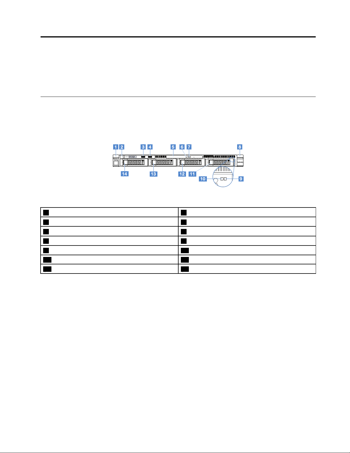
Frontview
Thefollowingillustrationshowsthecontrols,LEDs,andconnectorsonthefrontoftheserver.
Note:*Availableonservermodelswithhot-swapharddiskdrives
Figure3.Frontviewofservermodelswithfour3.5-inchharddiskdrives
1Rackreleaselatch(left)2Operatorinformationpanel
3USBconnector14USBconnector2
5Opticaldrivebay6OpticaldriveactivityLED
7Opticaldriveejectbutton8Rackreleaselatch(right)
9HarddiskdrivestatusLED*(yellow)10HarddiskdriveactivityLED*(green)
11Harddiskdrivebay312Harddiskdrivebay2
13Harddiskdrivebay114Harddiskdrivebay0
©CopyrightLenovo2016
13
Page 28
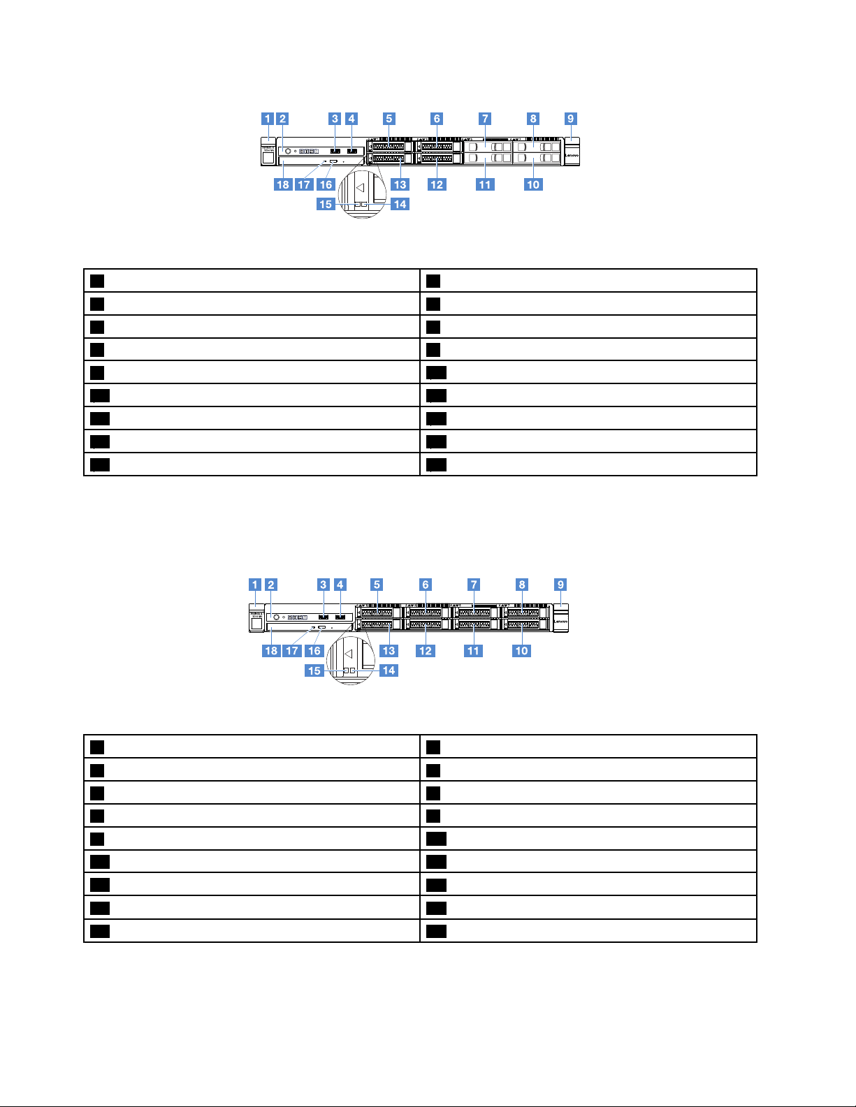
Figure4.Frontviewofservermodelswithfour2.5-inchharddiskdrives
1Rackreleaselatch(left)2Operatorinformationpanel
3USBconnector14USBconnector2
5Harddiskdrivebay06Harddiskdrivebay2
7Harddiskdrivebay48Harddiskdrivebay6
9Rackreleaselatch(right)
11Harddiskdrivebay512Harddiskdrivebay3
13Harddiskdrivebay1
15HarddiskdriveactivityLED*(green)16Opticaldriveejectbutton
17OpticaldriveactivityLED18Opticaldrivebay
10Harddiskdrivebay7
14HarddiskdrivestatusLED*(yellow)
Figure5.Frontviewofservermodelswitheight2.5-inchharddiskdrives
1Rackreleaselatch(left)2Operatorinformationpanel
3USBconnector14USBconnector2
5Harddiskdrivebay06Harddiskdrivebay2
7Harddiskdrivebay48Harddiskdrivebay6
9Rackreleaselatch(right)
11Harddiskdrivebay512Harddiskdrivebay3
13Harddiskdrivebay1
15HarddiskdriveactivityLED*(green)16Opticaldriveejectbutton
17OpticaldriveactivityLED18Opticaldrivebay
10Harddiskdrivebay7
14HarddiskdrivestatusLED*(yellow)
•Rackreleaselatches:
Pressthelatchesoneachfrontsideoftheservertoremovetheserverfromtherack.
14LenovoSystemx3250M6InstallationandServiceGuide
Page 29
•HarddiskdriveactivityLED:
ThisLEDisusedonhot-swapSASorSATAharddiskdrives.WhenthisLEDisflashing,itindicates
thatthedriveisinuse.
•HarddiskdrivestatusLED:
ThisLEDisusedonhot-swapSASorSATAharddiskdrives.WhenthisLEDislit,itindicatesthatthe
drivehasfailed.IfanoptionalServeRAIDcontrollerisinstalledintheserver,whenthisLEDisflashing
slowly(oneflashpersecond),itindicatesthatthedriveisbeingrebuilt.WhenthisLEDisflashingrapidly
(threeflashespersecond),itindicatesthatthecontrollerisidentifyingthedrive.
•USBconnectors:
ConnectaUSBdevice,suchasaUSBmouse,keyboard,orotherdevicetoanyoftheseconnectors.
•Opticaldriveejectbutton:
Pressthisbuttontoejectthedisctrayfromtheopticaldrive.
•OpticaldriveactivityLED:
WhenthisLEDislit,itindicatesthattheopticaldriveisinuse.
•Operatorinformationpanel:
ThispanelcontainscontrolsandLEDsthatprovideinformationaboutthestatusoftheserver.
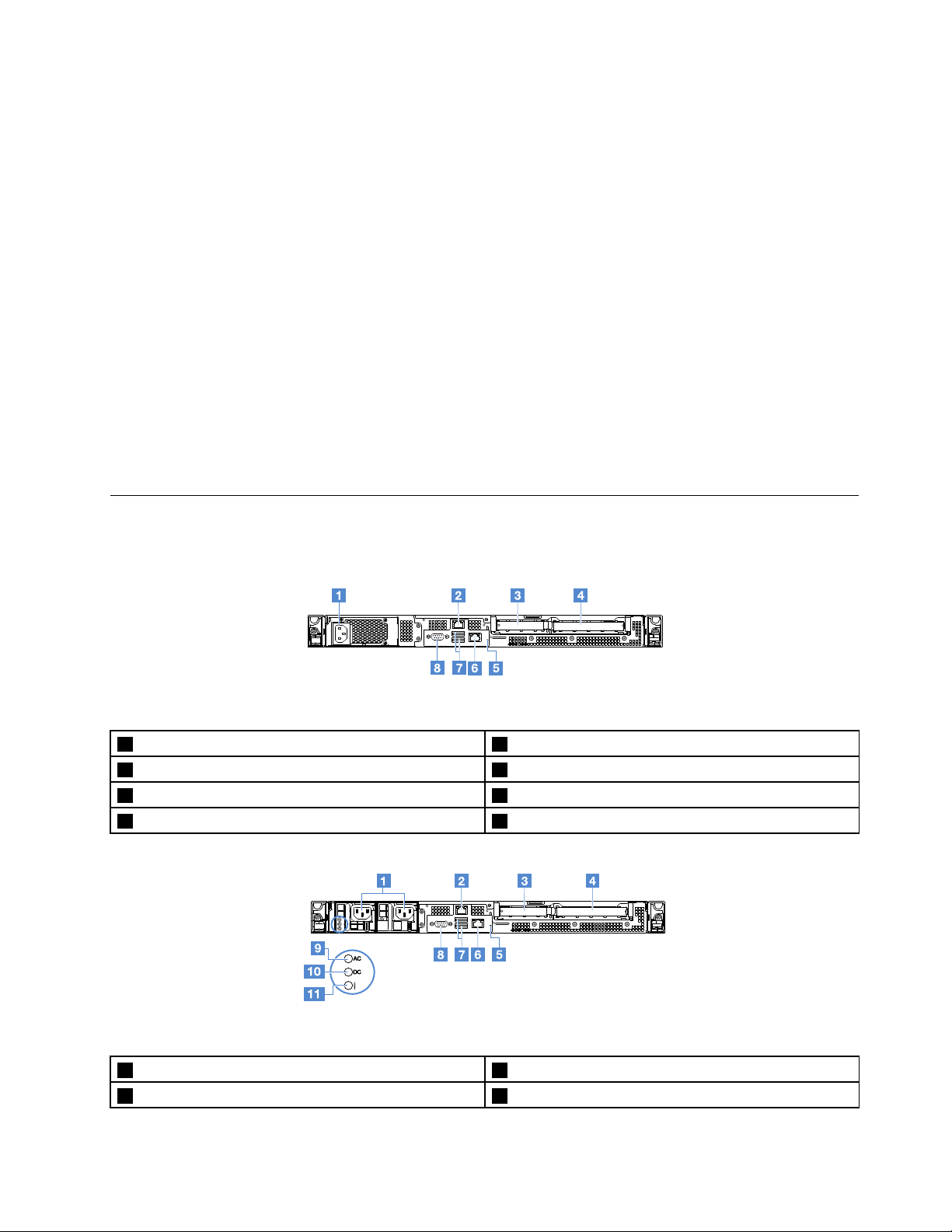
Rearview
ThefollowingillustrationsshowtheconnectorsandLEDsontherearoftheserver.
Figure6.Rearviewoftheserverwithfixedpower-supply
1Power-cordconnector2Ethernetconnector2
3PCIslot14PCIslot2
5NMIbutton
7USBconnectors8VGAconnector
Figure7.Rearviewoftheserverwiththeredundantpower-supplymodel
1Power-cordconnectors2Ethernetconnector2
3PCIslot14PCIslot2
6Ethernetconnector1forsystemmanagement
Chapter3.Componentlocations15
Page 30
5NMIbutton
7USBconnectors
9acpowerLED(green)10dcpowerLED(green)
11Power-supplyerrorLED(yellow)
1EthernetlinkLED
2EthernetactivityLED
6Ethernetconnector1forsystemmanagement
8Videoconnector
•EthernetlinkLEDs:WhentheseLEDsarelit,theyindicatethatthereisanactivelinkconnectiononthe
10BASE-T,100BASE-TX,or1000BASE-TXinterfacefortheEthernetconnector.
•EthernetactivityLEDs:WhentheseLEDsarelit,theyindicatethatthereisactivitybetweentheserver
andthenetwork.
•acpowerLED
•dcpowerLED
TheseLEDsshowthestatusofthepowersupply.Duringnormaloperation,bothofthemarelitingreen.
Formorepower-supplystatusinformation,see“Power-supplyLEDs”onpage52
.
•Power-supplyerrorLED:WhenthisyellowLEDislit,itindicatesthatthepowersupplyhasfailed.
•Powercordconnector:Connectthepowercordtothisconnector.
•VGAconnector:Connectamonitortothisconnector.
•USBconnectors:ConnectaUSBdevice,suchasaUSBmouse,keyboard,orotherdevicetoanyof
theseconnectors.
•Ethernetconnectors:Useeitheroftheseconnectorstoconnecttheservertoanetwork.Whenyouuse
theEthernet1connector,thenetworkcanbesharedwiththeIMM2throughasinglenetworkcable.
•NMIbutton:Pressthisbuttontoforceanonmaskableinterrupt(NMI)tothemicroprocessor.Bythis
way,youcanbluescreentheserverandtakeamemorydump.Youmighthavetouseapenortheend
ofastraightenedpapercliptopressthebutton.
Note:UsethisbuttononlywhendirectedbytheLenovoservicesupport.
•PCIslot1:ThisslotisdedicatedtoServeRAIDM1210SAS/SATAcontroller.
•PCIslot2:ThisslotsupportsonePCIExpressGen3x8half-length,full-heightadapter.
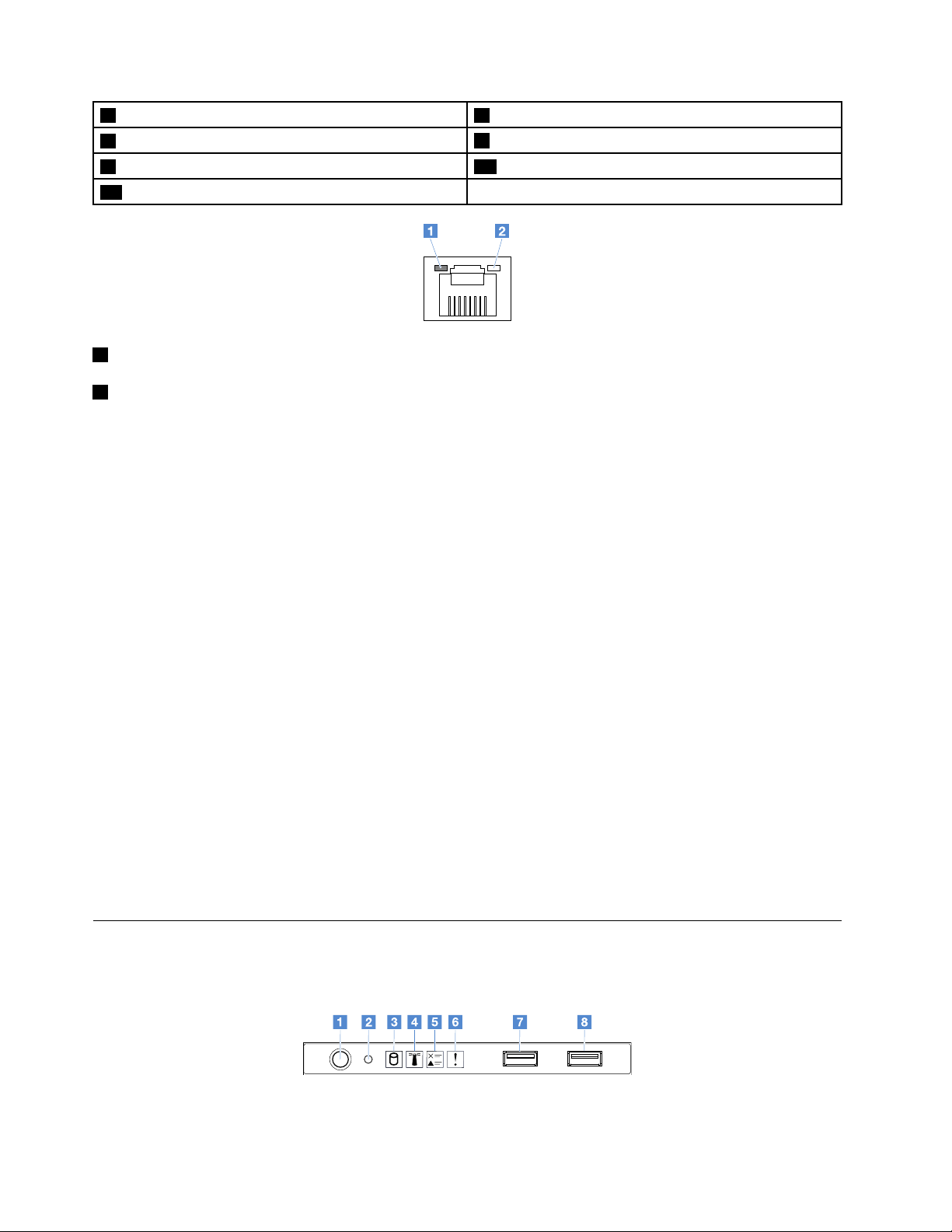
Operatorinformationpanel
ThefollowingillustrationshowsthecontrolsandLEDsontheoperatorinformationpanel.
Figure8.Operatorinformationpanel
16LenovoSystemx3250M6InstallationandServiceGuide
Page 31

1Power-controlbuttonand
power-onLED
2Resetbutton
3HarddiskdriveactivityLED
4System-locatorLED
5ChecklogLED
6System-errorLED
7USBconnector1
8USBconnector2
Pressthisbuttontoturnonorturnofftheservermanually.Thestatesofthe
power-onLEDareasfollows:
•Off:
Powerisnotpresent,otherwisethepowersupplyortheLEDitselfhas
failed.
•Flashingrapidly(fourtimespersecond):
Theserveristurnedoffandisnotreadytobeturnedon.Thepower-control
buttonisdisabled.Thiswilllastapproximately20seconds.
•Flashingslowly(oncepersecond):
Theserveristurnedoffandisreadytobeturnedon.Y oucanpressthe
power-controlbuttontoturnontheserver.
•On:Theserveristurnedon.
Pressthisbuttontoresettheserverandrunthepower-onself-test(POST).
Youmighthavetouseapenortheendofastraightenedpapercliptopress
thebutton.
WhenthisLEDisflashing,itindicatesthattheassociatedharddiskdrive
isinuse.
UsethisblueLEDtolocatetheserveramongotherserversvisually.ThisLED
isalsousedasapresencedetectionbutton.YoucanuseLenovoXClarity
AdministratortolightthisLEDremotely.
WhenthisyellowLEDislit,itindicatesthatasystemerrorhasoccurred.
Checktheeventlogforadditionalinformation.Formoreinformation,see
“Eventlogs”onpage54.
WhenthisyellowLEDislit,itindicatesthatasystemerrorhasoccurred.For
moreinformation,see“Eventlogs”onpage54.
ConnectaUSBdevice,suchasaUSBmouse,keyboard,orotherdevice
toanyoftheseconnectors.
Servercomponents
Thefollowingillustrationshowsthemajorcomponentsintheserver.
Theillustrationsinthisdocumentmightdifferslightlyfromyourhardware.
Chapter3.Componentlocations17
Page 32

Figure9.Servercomponents
1Servercover
3Heatsink
5Fixedpowersupply*
4
2
2
7Chassisof3.5-inchharddiskdrivemodelwith
hot-swappowersupply*
9Powerdistributionboard*
4
2
113.5-inchsimple-swaphard-disk-drivebackplate
assembly*
2
133.5-inchhot-swaphard-disk-drivebackplane*
15Chassisof2.5-inchharddiskdrivemodelwithfixed
powersupply*
173.5-inchharddiskdrivefiller*
4
4
18LenovoSystemx3250M6InstallationandServiceGuide
2Airbaffle
4Memorymodule
6Hot-swappowersupply*
8Powerdistributionboardcover*
4
1
1
4
102.5-inchsimple-swaphard-disk-drivebackplate
assembly*
122.5-inchhot-swaphard-disk-drivebackplane*
1
14Securitybezel
16Opticaldrive
183.5-inchhot-swapharddiskdrive*
2
1
3
1
1
Page 33

193.5-inchsimple-swapharddiskdrive*
212.5-inchsimple-swapharddiskdrive*
232.5-inchharddiskdrivefiller(foroneharddiskdrive)*
25Systemboard
27Systemfan
29PCIriser-cardassembly*
2
1
1
1
1
202.5-inchhot-swapharddiskdrive*
222.5-inchharddiskdrivefiller(fortwoharddiskdrives)*
3
1
24FrontI/Oassembly
26RAIDadapterbatteryorflashpowermoduleholder*
28Microprocessor
30RAIDcard*
1
1
2
1
Blueonacomponentindicatestouchpoints,whereyoucangripthecomponenttoremoveitfromorinstall
itintheserver,openorclosealatch,andsoon.
Orangeonacomponentoranorangelabelonornearacomponentindicatesthatthecomponentcanbe
hot-swapped.Thismeansthatiftheserverandoperatingsystemsupporthot-swapcapability,youcan
removeorinstallthecomponentwhiletheserverisrunning.Orangecanalsoindicatetouchpointson
hot-swapcomponents.
Notes:
•*Availableonsomemodels
1
•
Tier1customerreplaceableunit(CRU):ReplacementofTier1CRUsisyourresponsibility.IfLenovo
installsaTier1CRUatyourrequest,youwillbechargedfortheinstallation.
2
•
Tier2customerreplaceableunit(CRU):Y oumayinstallaTier2CRUyourselforrequestLenovotoinstall
it,atnoadditionalcharge,underthetypeofwarrantyservicethatisdesignatedforyourserver.
3
•
Structuralparts:Purchaseandreplacementofstructuralparts(suchaschassisassembly,cover,and
bezel)isyourresponsibility.IfLenovoacquiresorinstallsastructuralpartatyourrequest,youwill
bechargedfortheservice.
4
•
Consumableparts:PartsthatarepurchasedseparatelyandnotcoveredbytheLenovoStatementof
LimitedWarranty.
4
BeforeservicingaLenovoproduct,ensurethatyoureadandunderstand“Safety”onpagev
providedbyLenovoforreplacement.ForacompletelistingofFRUinformation,suchasFRUpartnumbers
andsupportedservermodels,goto:
http://www.lenovo.com/serviceparts-lookup
System-boardconnectors
Thefollowingillustrationshowstheconnectorsonthesystemboard.
.Useonlyparts
Chapter3.Componentlocations19
Page 34

Figure10.Connectorsonthesystemboard
1PCIrisercardconnector
3Powersupplyconnector4Backplanepowerconnector
5DIMMslot16DIMMslot2
7DIMMslot38DIMMslot4
9Powerdistributionboardconnector
11Systemfan2connector12Systemfan3connector
13Systemfan4connector14Mini-SASconnector
15SATAopticaldriveconnector16Operationinformationpanelconnector
17Coin-cellbatteryconnector18FrontUSBconnector
19USBhypervisorkeyconnector20Operatingtemperatureenhancementkitconnector
2Microprocessorpowerconnector
10Systemfan1connector
System-boardswitchesandjumpers
Thistopichelpsyoulocatethejumpersandswitchesonthesystemboardandgetfamiliarwiththeir
functions.
Important:
•Beforeyouchangeanyswitchsettingsormoveanyjumpers,turnofftheserver.Then,disconnectall
powercordsandexternalcables.Reviewtheinformationin“Safety”onpagev,“Beforeremovingor
installingservercomponents”onpage85,and“Turningofftheserver”onpage11.
•Anysystem-boardswitchorjumperblockthatisnotshownintheillustrationsinthisdocumentare
reserved.
•Ifthereisaclearprotectivestickerontheswitchblocks,youmustremoveanddiscardittoaccess
theswitches.
20LenovoSystemx3250M6InstallationandServiceGuide
Page 35

1
2
3
3
2
1
1 2 3
1 2 3
5
On
Off
48 3
7
26 1
5
Figure11.Switchesandjumpersonthesystemboard
1ClearCMOSjumper2UEFIbootbackupjumper(JP24)
3TPMphysicalpresencejumper(JP39)4ShareNICjumper
5SW1switchblock
Thefollowingtabledescribesthejumpersonthesystemboard.
Table2.Jumpersdefinition
JumpernameDescription
ClearCMOSjumper•Pins1and2(default):KeeptheCMOSdata.
UEFIbootbackup
jumper
•Pins2and3:CleartheCMOSdata.
•Pins1and2(default):LoadtheprimaryserverfirmwareROMpage.
•Pins2and3:Bootfrombackupandloadthesecondary(backup)serverfirmware
ROMpage.
TPMphysicalpresence
jumper
•Pins1and2:Defaultoff
•Pins2and3:IndicatesaphysicalpresencetothesystemTPM.
ShareNICjumper•Pins1and2:Defaulton.ShareLAN.
•Pins2and3:SetEthernetconnector1asthededicatedmanagementportofIMM.
Ifnojumperispresent,theserverrespondsasifthepinsaresettothedefault.
Chapter3.Componentlocations21
Page 36

Note:ChangingthepositionoftheUEFIbootbackupjumperfrompins1and2topins2and3beforethe
serveristurnedonalterswhichflashROMpageisloaded.Donotchangethejumperpinpositionafterthe
serveristurnedon.Thiscancauseanunpredictableproblem.
Table3.SW1switchblockdefinition
SwitchnumberDefaultpositionDescription
1,3,4,5,6,7,8
2
Off
OffPower-onpasswordoverrides.Changingthepositionofthisswitch
Reserved.
bypassesthepower-onpasswordcheckthenexttimetheserver
isturnedonandstartstheSetupUtilitysothatyoucanchange
ordeletethepower-onpassword.Youdonothavetomovethe
switchbacktothedefaultpositionafterthepower-onpassword
inoverridden.
Changingthepositionofthisswitchdoesnotaffecttheadministrator
passwordcheckifanadministratorpasswordisset.
See“Passwords”onpage30
passwords.
foradditionalinformationabout
System-boardLEDs
Thefollowingillustrationshowsthelight-emittingdiodes(LEDs)onthesystemboard.
Figure12.LEDsonthesystemboard
1ComplexProgrammableLogicDevice(CPLD)
heartbeatLED
3IMMheartbeatLED
5System-locatorLED6Field-ProgrammableGateArray(FPGA)errorLED
2PowerLED
4System-errorLED
22LenovoSystemx3250M6InstallationandServiceGuide
Page 37

Chapter4.Configurationinformation
Thischapterprovidesinformationaboutupdatingthefirmwareandusingtheconfigurationutilities.
Updatingthefirmware
Important:
•Someclustersolutionsrequirespecificcodelevelsorcoordinatedcodeupdates.Ifthedeviceispart
ofaclustersolution,verifythatthelatestlevelofcodeissupportedfortheclustersolutionbeforeyou
updatethecode.
•Beforeyouupdatethefirmware,besuretobackupanydatathatisstoredintheTrustedPlatformModule
(TPM),incaseanyoftheTPMcharacteristicsarechangedbythenewfirmware.Forinstructions,seeyour
encryptionsoftwaredocumentation.
•Installingthewrongfirmwareordevice-driverupdatemightcausetheservertomalfunction.Beforeyou
installafirmwareordevice-driverupdate,readanyreadmeandchangehistoryfilesthatareprovided
withthedownloadedupdate.Thesefilescontainimportantinformationabouttheupdateandthe
procedureforinstallingtheupdate,includinganyspecialprocedureforupdatingfromanearlyfirmwareor
device-driverversiontothelatestversion.
YoucaninstallcodeupdatesthatarepackagedasanUpdateXpressSystemPackorUpdateXpressCD
image.AnUpdateXpressSystemPackcontainsanintegration-testedbundleofonlinefirmwareand
device-driverupdatesforyourserver.UseUpdateXpressSystemPackInstallertoacquireandapply
UpdateXpressSystemPacksandindividualfirmwareanddevice-driverupdates.Foradditionalinformation
andtodownloadtheUpdateXpressSystemPackInstaller,gototheToolsCenterforSystemxand
BladeCenterathttps://support.lenovo.com/us/en/documents/LNVO-CENTERandclickUpdateXpress
SystemPackInstaller.
Whenyouclickanupdate,aninformationpageisdisplayed,includingalistoftheproblemsthattheupdate
fixes.Reviewthislistforyourspecificproblem;however,evenifyourproblemisnotlisted,installingthe
updatemightsolvetheproblem.
Besuretoseparatelyinstallanylistedcriticalupdatesthathavereleasedatesthatarelaterthantherelease
dateoftheUpdateXpressSystemPackorUpdateXpressimage.
ThefirmwarefortheserverisperiodicallyupdatedandisavailablefordownloadontheLenovoWebsite.To
checkforthelatestleveloffirmware,suchastheUEFIfirmware,devicedrivers,andIntegratedManagement
ModuleII(IMM2)firmware,gotohttp://www.ibm.com/support/fixcentral.
Downloadthelatestfirmwarefortheserver;then,installthefirmware,usingtheinstructionsthatareincluded
withthedownloadedfiles.
Whenyoureplaceadeviceintheserver,youmighthavetoupdatethefirmwarethatisstoredinmemoryon
thedeviceorrestorethepre-existingfirmwarefromaCDorDVDimage.
Thefollowinglistindicateswherethefirmwareisstored:
•UEFIfirmwareisstoredinROMonthesystemboard.
•IMM2firmwareisstoredinROMonthesystemboard.
•EthernetfirmwareisstoredinROMontheEthernetcontrollerandonthesystemboard.
•ServeRAIDfirmwareisstoredinROMonthePCIeRAIDadapter(ifoneisinstalled).
©CopyrightLenovo2016
23
Page 38

•SAS/SATAfirmwareisstoredinROMontheSAS/SATAcontrolleronthesystemboard.
Configuringtheserver
Toconfigureyourserver,considerthefollowingvariousaspects:
•SetupUtility
SetupUtilityispartoftheUEFIfirmware.UseSetupUtilitytochangeinterruptrequest(IRQ)settings,
changethestartup-devicesequence,setsystemdateandtime,setpasswords,andperformother
configurationtasks.Formoreinformation,see“UsingtheSetupUtilityprogram”onpage26
•BootManager
BootManagerispartoftheUEFIfirmware.UseBootManagertooverridethestartupsequencethatisset
intheSetupUtilityandtemporarilyassignafirststartupdevice.Formoreinformation,see“Usingthe
BootManagerprogram”onpage32.
•LenovoServerGuideSetupandInstallationCD
TheServerGuideprogramisavailableontheServerGuideSetupandInstallationCD.Thisprogram
providessoftware-setuptoolsandinstallationtoolsthataredesignedfortheserver.UsethisCDduring
theinstallationoftheservertoconfigurebasichardwarefeatures,suchasanintegratedSAS/SATA
controllerwithRAIDcapabilities,andtosimplifytheinstallationofyouroperatingsystem.Formore
information,see“UsingtheServerGuideSetupandInstallationCD”onpage25
•IntegratedManagementModuleII(IMM2)
UsetheIntegratedManagementModuleII(IMM2)toconfiguretheserver,updatethefirmware,update
thesensordatarecord/fieldreplaceableunit(SDR/FRU)data,andremotelymanageanetwork.For
informationaboutusingtheIMM2,see“UsingtheIntegratedManagementModuleII(IMM2)”onpage33
•VMwareESXiembeddedhypervisor
AnoptionalUSBflashdevicewithVMwareESXiembeddedhypervisorsoftwareisavailableforpurchase.
Hypervisorisvirtualizationsoftwarethatenablesmultipleoperatingsystemstorunonahostsystemat
thesametime.Formoreinformationaboutusingtheembeddedhypervisor,see“Usingtheembedded
hypervisor”onpage35.
•Remotepresencecapabilityandblue-screencapture
Theremotepresenceandblue-screencaptureareintegratedfeaturesoftheIntegratedManagement
ModuleII(IMM2).Theremotepresencefeatureprovidesthefollowingfunctions:
.
.
.
–Remotelyviewingvideoswithgraphicsresolutionsupto1600x1200at75Hz,regardlessofthe
systemstate
–Remotelyaccessingtheserver,usingthekeyboardandmousefromaremoteclient
–MappingtheCDorDVDdrive,andUSBflashdriveonaremoteclient,andmappingISOimagefilesas
virtualdrivesthatareavailableforusebytheserver
–UploadingadisketteimagetotheIMM2memoryandmappingittotheserverasavirtualdrive
Theblue-screencapturefeaturecapturesthevideodisplaycontentsbeforetheIMM2restartsthe
serverwhentheIMM2detectsanoperating-systemhangcondition.Asystemadministratorcanuse
theblue-screencapturefeaturetoassistindeterminingthecauseofthehangcondition.Formore
information,see“Usingtheremotepresenceandblue-screencapturefeatures”onpage34
•Ethernetcontrollerconfiguration
ForinformationaboutconfiguringtheEthernetcontroller,see“Ethernetcontrollerinformation”onpage36
•FeaturesonDemand
TheserverprovidestheFeaturesonDemand(FoD)softwareEthernetsupport.Y oucanpurchaseaFoD
softwareupgradekeyforFibreChanneloverEthernet(FCoE)andiSCSIstorageprotocols.Formore
information,see“EnablingFeaturesonDemandEthernetandDemandRAIDsoftware”onpage36
24LenovoSystemx3250M6InstallationandServiceGuide
.
.
.
Page 39

•T oolsCenterSuitCLIprogram
TheLenovoT oolsCenterSuiteCLIprogramisacollectionofservermanagementtoolsthatutilizea
command-lineinterfaceprogramtomanagefirmware,hardware,andoperatingsystems.Itcoversthe
configurationfunction,whichisanalternativetoSetupUtilityformodifyingUEFIsettings.Formore
informationaboutusingthisprogram,see“LenovoToolsCenterSuiteCLIprogram”onpage37
•RAIDconfiguration
ForinformationaboutconfiguringRAID,see“AccessingRAIDconfigurationutility”onpage36.
ThefollowingtableliststheapplicationsthatareavailableforconfiguringandmanagingRAID.
Table4.ServerconfigurationandapplicationsforconfiguringandmanagingRAID
.
RAIDconfiguration(before
Serverconfiguration
ServeRAIDM1210SAS/SATA
Controller
ServeRAIDM1215SAS/SATA
Controller
ServeRAIDM5210SAS/SATA
Controller
ServeRAIDM5225-2GBSAS/SATA
Controller
SoftwareRAID–IntelUtility:(PressCtrl+IinSetup
operatingsystemisinstalled)
–LSIUtility:(PressCtrl+CinSetup
Utilitywhenunderthelegacy
BIOSboot.)
–ServerGuide
–HumanInterfaceInfrastructure
(HII)
Utilitywhenunderthelegacy
BIOSboot)
–ServerGuide
–HumanInterfaceInfrastructure
(HII)
FormoreinformationaboutHumanInterfaceInfrastructure(HII)andStorCLI,goto:
http://public.dhe.ibm.com/systems/support/system_x_pdf/
ibm_doc_mpt2sas_hiic-2011-09_user-guide.pdf
FormoreinformationaboutMegaRAID,goto:
http://www.ibm.com/support/entry/portal/docdisplay?lndocid=MIGR-5073015
UsingtheServerGuideSetupandInstallationCD
RAIDmanagement(afterinstalling
theoperatingsystem)
–MegaRAIDStorageManager
(MSM),
–StorCLI(CommandLine)Utility
forStorageManagement
–Graphicalutility(Windowsonly)
–CommandLine:rstcli(Windows)
andmdadm(Linux)Utilityfor
StorageManagement
UsethisinformationasanoverviewforusingtheServerGuideSetupandInstallationCD.
TheServerGuideSetupandInstallationCDprovidessoftwaresetuptoolsandinstallationtoolsthatare
designedforyourserver.TheServerGuideprogramdetectstheservermodelandoptionalhardware
devicesthatareinstalledandusesthatinformationduringsetuptoconfigurethehardware.ServerGuide
simplifiestheoperating-systeminstallationsbyprovidingupdateddevicedriversand,insomecases,
installingthemautomatically.
WhenusingServerGuidetodeployWindows2008series,ServerGuidemightrunintoabluescreenonyour
systemwithorwithoutServeRAIDC110enabled.T oavoidthisproblem,dothefollowing:
1.SetUEFIsettings.
2.ViewtheDeviceandI/OPortssetting.
3.Dooneofthefollowingandsavethechanges:
•IftheServeRAIDC110isenabled,changetheonboardSA TAportsasintoRAIDorIDE.
•IftheServeRAIDC110isnotenabled,changetheonboardSATAportsasintoIDE.
Aftersavingthesettings,thesystemwillreturntonormalwhenrebootingfromServerGuide.
Chapter4.Configurationinformation25
Page 40

YoucandownloadafreeimageoftheServerGuideSetupandInstallationCDfrom:
http://www.ibm.com/support/entry/portal/docdisplay?lndocid=SERV-GUIDE
InadditiontotheServerGuideSetupandInstallationCD,youmusthaveyouroperating-systemdiscto
installtheoperatingsystem.
ServerGuidefeatures
AvailablefeaturesmightvaryslightlywithdifferentversionsoftheServerGuideprogram.Tolearnmoreabout
theversionthatyouhave,starttheServerGuideSetupandInstallationCDandreadtheonlineoverview.
Notallfeaturesaresupportedonallservermodels.
TheServerGuideprogramhasthefollowingfeatures:
•Aneasy-to-useinterface
•Diskette-freesetup,andconfigurationprogramsthatarebasedonthedetectedhardware
•Devicedriversthatareprovidedfortheservermodelanddetectedhardware
•Selectableoperating-systempartitionsizeandfile-systemtypeduringsetup
•Onlinereadmefilewithlinkstotipsforyourhardwareandoperating-systeminstallation
•Settingystemdateandtime
Setupandconfigurationoverview
YoucanusetheServerGuideSetupandInstallationCDtoconfigureanysupportedLenovoservermodel.
Thesetupprogramprovidesalistoftasksthatarerequiredtosetupyourservermodel.Onaserverwith
aServeRAIDadapterorSAS/SATAcontrollerwithRAIDcapabilities,youcanruntheSAS/SATARAID
configurationprogramtocreatelogicaldrives.
Typicaloperating-systeminstallationbyusingServerGuide
ThissectiondetailstheServerGuidetypicaloperating-systeminstallation.
TheServerGuideprogramcanreducethetimeforinstallinganoperatingsystem.Itprovidesthedevice
driversthatarerequiredforyourhardwareandfortheoperatingsystemthatyouareinstalling.Refertothe
followinglistforatypicaloperating-systeminstallationbyusingServerGuide:
1.Afteryouhavecompletedthesetupprocess,theoperating-systeminstallationprogramstarts.(Y ou
needyouroperating-systemdisctocompletetheinstallation.)
2.TheServerGuideprogramstoresinformationabouttheservermodel,serviceprocessor,harddiskdrive
controllers,andEthernetcontrollers.Then,theprogramcheckstheCDforanyupdateddevicedrivers.
Thisinformationisstoredandthenpassedtotheoperating-systeminstallationprogram.
3.TheServerGuideprogrampresentsoperating-systempartitionoptionsthatarebasedonyour
operating-systemselectionandtheinstalledharddiskdrives.
4.TheServerGuideprogrampromptsyoutoinsertyouroperating-systemCDandrestarttheserver.At
thispoint,theinstallationprogramfortheoperatingsystemtakescontroltocompletetheinstallation.
Operating-systeminstallationwithoutusingServerGuide
IfyouhavealreadyconfiguredtheserverhardwareandyouarenotusingtheServerGuideprogramto
installyouroperatingsystem,youcandownloadoperating-systeminstallationinstructionsfortheserver
fromhttp://www.lenovo.com/support.
UsingtheSetupUtilityprogram
UsetheUnifiedExtensibleFirmwareInterface(UEFI)SetupUtilityprogramtoperformthefollowingtasks:
•Viewconfigurationinformation.
•ViewandchangeassignmentsfordevicesandI/Oports.
26LenovoSystemx3250M6InstallationandServiceGuide
Page 41

•Setthedateandtime.
•Setandchangepasswords.
•Setthestartupcharacteristicsoftheserverandtheorderofstartupdevices.
•Setandchangesettingsforadvancedhardwarefeatures.
•View,set,andchangesettingsforpower-managementfeatures.
•Viewandclearerrorlogs.
•Changeinterruptrequest(IRQ)settings.
•Resolveconfigurationconflicts.
StartingtheSetupUtilityprogram
TostarttheSetupUtilityprogram,dothefollowing:
Step1.T urnontheserver.
Note:Approximately20secondsaftertheserverisconnectedtopower,thepower-controlbutton
becomesactive.
Step2.Whentheprompt<F1>Setupisdisplayed,pressF1.Ifyouhavesetanadministratorpassword,
youmusttypetheadministratorpasswordtoaccessthefullSetupUtilitymenu.Ifyoudonottype
theadministratorpassword,alimitedSetupUtilitymenuisavailable.
Step3.Selectsettingstovieworchangeaccordingtoyourneeds.
SetupUtilitymenuchoices
UsetheSetupUtilitymainmenutoviewandconfiguretheserversettings.
ThefollowingchoicesareontheSetupUtilitymainmenufortheUEFI.Dependingontheversionofthe
firmware,somemenuchoicesmightdifferslightlyfromthesedescriptions.
•SystemInformation(availableonthefullSetupUtilitymenuonly)
Selectthischoicetoviewinformationabouttheserver.Whenyoumakechangesthroughotherchoices
inSetupUtility,someofthosechangesarereflectedinthesysteminformation;youcannotchange
settingsdirectlyinthesysteminformation.
–SystemSummary
Selectthischoicetoviewconfigurationinformation,includingtheID,speed,andcachesizeofthe
microprocessors;machinetypeandmodeloftheserver;theserialnumber;thesystemUUID;andthe
amountofinstalledmemory.WhenyoumakeconfigurationchangesthroughotheroptionsinSetup
Utility,thechangesarereflectedinthesystemsummary;youcannotchangesettingsdirectlyin
thesystemsummary.
–ProductData(availableonthefullSetupUtilitymenuonly)
Selectthischoicetoviewthesystem-boardidentifier,therevisionlevelorissuedateofthefirmware,
theIntegratedManagementModuleII(IMM2)anddiagnosticscode,andtheversionanddate.
•SystemSettings
Selectthischoicetovieworchangetheservercomponentsettings.
–AdaptersandUEFIDrivers
SelectthischoicetoviewinformationabouttheUEFI1.10andUEFI2.0compliantadaptersand
driversinstalledintheserver.
–Processors
Selectthischoicetovieworchangetheprocessorsettings.
Chapter4.Configurationinformation27
Page 42

–Memory
Selectthischoicetovieworchangethememorysettings.
–DevicesandI/OPorts
Selectthischoicetovieworchangeassignmentsfordevicesandinput/output(I/O)ports.Y oucan
configuretheserialportsandremoteconsoleredirection.Youalsocanenableordisableintegrated
Ethernetcontrollers,theSAS/SATAcontrollers,SATAopticaldrivechannels,PCIslots,andvideo
controller.Ifyoudisableadevice,itcannotbeconfigured,andtheoperatingsystemwillnotbeableto
detectit(thisisequivalenttodisconnectingthedevice).
–OperatingModes
Selectthischoicetovieworchangetheoperatingprofile(performanceandpowerutilization).
–LegacySupport
Selectthischoicetovieworsetthelegacysupport.
–ForceLegacyVideoonBoot
SelectthischoicetoforceINTvideosupport,iftheoperatingsystemdoesnotsupportUEFIvideo
outputstandards.
–RehookINT19h
Selectthischoicetoenableordisabledevicesfromtakingcontrolofthebootprocess.The
defaultsettingisDisable.
–LegacyThunkSupport
SelectthischoicetoenableordisableUEFItointeractwithPCImassstoragedevicesthatare
non-UEFIcompliant.ThedefaultsettingisEnable.
–InfiniteBootRetry
SelectthischoicetoenableordisableUEFItoretrythelegacybootorderinfinitely.Thedefault
settingisDisable.
–Non-PlanarPXE
Selectthischoicetoenableordisablenon-system-boardPrebootExecutionEnvironment(PXE)
forlegacymode.
–BBSBoot
SelectthischoicetoenableordisablelegacybootinBIOSBootSpecification(BBS)manner.
ThedefaultisEnable.
–SystemSecurity
SelectthischoicetovieworconfiguretheT rustedPlatformModule(TPM)support.
–IntegratedManagementModuleII(IMM2)
SelectthischoicetovieworchangethesettingsfortheIntegratedManagementModuleII(IMM2).
–PowerRestorePolicy
Selectthischoicetosetthemodeofoperationafterpowerloss.
–CommandsonUSBInterface
SelectthischoicetoenableordisabletheEthernetoverUSBinterfaceonIMM2.Thedefault
settingisEnable.
–NetworkConfiguration
Selectthischoicetoviewthesystemmanagementnetworkinterfaceport,theIMM2MACaddress,
thecurrentIMM2IPaddress,andhostname;definethestaticIMM2IPaddress,subnetmask,and
gatewayaddress;specifywhethertousethestaticIPaddressorhaveDHCPassigntheIMM2IP
address;savethenetworkchanges;andresettheIMM2.
28LenovoSystemx3250M6InstallationandServiceGuide
Page 43

–ResetIMM2toDefaults
SelectthischoicetovieworresettheIMM2tothedefaultsettings.
–ResetIMM2
SelectthischoicetoresettheIMM2.
–RecoveryandRAS
SelectthischoicetovieworchangethePOSTattemptsandsystemrecoverysettings.
–POSTAttempts
SelectthischoicetovieworchangethenumberofattemptstoPOST.
•POSTAttemptsLimit
SelectthischoicetovieworchangetheNxbootfailureparameters.
–SystemRecovery
Selectthischoicetovieworchangesystemrecoverysettings.
•POSTWatchdogTimer
SelectthischoicetovieworenablethePOSTwatchdogtimer.
•POSTWatchdogTimerValue
SelectthischoicetovieworsetthePOSTloaderwatchdogtimervalue.
•RebootSystemonNMI
Selectthischoicetoenableordisablerestartingthesystemwheneveranonmaskableinterrupt
(NMI)occurs.ThedefaultsettingisEnable.
–Storage
Selectthischoicetovieworchangethestoragedevicesettings.
–Network
Selectthischoicetovieworchangethenetworkdeviceoptions,suchasiSCSI.
–DriveHealth
Selectthischoicetoviewthestatusofthecontrollersinstalledinthebladeserver.
•DateandTime(availableonthefullSetupUtilitymenuonly)
Selectthischoicetosetthedateandtimeintheserver,in24-hourformat(hour:minute:second).
•StartOptions(availableonthefullSetupUtilitymenuonly)
Selectthischoicetovieworchangethestartoptions,includingthestartupsequence,keyboardNumLock
state,PXEbootoption,andPCIdevicebootpriority.Changesinthestartupoptionstakeeffectwhenyou
starttheserver.
Thestartupsequencespecifiestheorderinwhichtheserverchecksdevicestofindabootrecord.The
serverstartsfromthefirstbootrecordthatitfinds.IftheserverhasWakeonLANhardwareandsoftware
andtheoperatingsystemsupportsWakeonLANfunctions,youcanspecifyastartupsequenceforthe
WakeonLANfunctions.Forexample,youcandefineastartupsequencethatchecksforadiscinthe
CD-RW/DVDdrive,thencheckstheharddiskdrive,andthenchecksaEthernetcontroller.
•BootManager
Selectthischoicetoview,add,delete,orchangethedevicebootpriority,bootfromafile,selecta
one-timeboot,orresetthebootordertothedefaultsetting.
•SystemEventLog(availableonthefullSetupUtilitymenuonly)
SelectthischoicetoentertheSystemEventManager,whereyoucanviewthePOSTeventlogandthe
system-eventlog.Youcanusethearrowkeystomovebetweenpagesintheerrorlog.
POSTeventlogcontainsthemostrecenterrorcodesandmessagesthatweregeneratedduringthePOST.
Chapter4.Configurationinformation29
Page 44

System-eventlogcontainsPOSTandsystemmanagementinterrupt(SMI)eventsandalleventsthatare
generatedbythebaseboardmanagementcontrollerthatisembeddedintheIntegratedManagement
ModuleII(IMM2).
Important:Ifthesystem-errorLEDonthefrontoftheserverislitbuttherearenoothererrorindications,
clearthesystem-eventlog.Also,afteryoucompletearepairorcorrectanerror,clearthesystem-event
logtoturnoffthesystem-errorLEDonthefrontoftheserver.
–POSTEventViewer
SelectthischoicetoenterthePOSTeventviewertoviewthePOSTerrormessages.
–SystemEventLog
Selectthischoicetoviewthesystemeventlog.
–ClearSystemEventLog
Selectthischoicetoclearthesystemeventlog.
•UserSecurity
Selectthischoicetoset,change,orclearpasswords.Formoreinformation,see“Passwords”onpage30
–SetPower-onPassword
Selectthischoicetosetorchangeapower-onpassword.Formoreinformation,see“Power-on
password”onpage31.
–ClearPower-onPassword
Selectthischoicetoclearapower-onpassword.Formoreinformation,see“Power-onpassword”
onpage31.
–SetAdministratorPassword
Selectthischoicetosetorchangeanadministratorpassword.Anadministratorpasswordisintended
tobeusedbyasystemadministrator;itlimitsaccesstothefullSetupUtilitymenu.Ifanadministrator
passwordisset,thefullSetupUtilitymenuisavailableonlyifyoutypetheadministratorpasswordat
thepasswordprompt.Formoreinformation,see“Administratorpassword”onpage31
–ClearAdministratorPassword
Selectthischoicetoclearanadministratorpassword.Formoreinformation,see“Administrator
password”onpage31.
•SaveSettings
SelectthischoicetosavethechangesthatyouhavemadeinSetupUtility.
•RestoreSettings
SelectthischoicetocancelthechangesthatyouhavemadeinSetupUtilityandrestoretheprevious
settings.
•LoadDefaultSettings
SelectthischoicetocancelthechangesthatyouhavemadeinSetupUtilityandrestorethefactory
settings.
•ExitSetup
SelectthischoicetoexitSetupUtility.IfyouhavenotsavedthechangesthatyouhavemadeinSetup
Utility,youwillbeaskedwhetheryouwanttosavethechangesorexitwithoutsavingthem.
.
.
Passwords
FromtheUserSecuritymenuchoice,youcanset,change,anddeleteapower-onpasswordandan
administratorpassword.
TheUserSecuritymenuchoiceisonthefullSetupUtilitymenuonly.
30LenovoSystemx3250M6InstallationandServiceGuide
Page 45

Ifyousetonlyapower-onpassword,youmusttypethepower-onpasswordtocompletethesystemstartup
andtohaveaccesstothefullSetupUtilitymenu.
Anadministratorpasswordisintendedtobeusedbyasystemadministrator;itlimitsaccesstothefullSetup
Utilitymenu.Ifyousetonlyanadministratorpassword,youdonothavetotypeapasswordtocompletethe
systemstartup,butyoumusttypetheadministratorpasswordtoaccesstheSetupUtilitymenu.
Ifyousetapower-onpasswordforauserandanadministratorpasswordforasystemadministrator,you
musttypethepower-onpasswordtocompletethesystemstartup.Asystemadministratorwhotypesthe
administratorpasswordhasaccesstothefullSetupUtilitymenu;thesystemadministratorcangivetheuser
authoritytoset,change,anddeletethepower-onpassword.Auserwhotypesthepower-onpasswordhas
accesstoonlythelimitedSetupUtilitymenu;theusercanset,change,anddeletethepower-onpassword,
ifthesystemadministratorhasgiventheuserthatauthority.
Power-onpassword
Ifapower-onpasswordisset,whenyouturnontheserver,youmusttypethepower-onpasswordto
completethesystemstartup.Youcanuseanycombinationof6-20printableASCIIcharactersforthe
password.
Whenapower-onpasswordisset,youcanenabletheUnattendedStartmode,inwhichthekeyboardand
mouseremainlockedbuttheoperatingsystemcanstart.Youcanunlockthekeyboardandmouseby
typingthepower-onpassword.
Ifyouforgetthepower-onpassword,youcanregainaccesstotheserverinanyofthefollowingways:
•Ifanadministratorpasswordisset,typetheadministratorpasswordatthepasswordprompt.Startthe
SetupUtilityandresetthepower-onpassword.
Attention:Ifyousetanadministratorpasswordandthenforgetit,thereisnowaytochange,override,or
removeit.Youmustreplacethesystemboard.
•Removethebatteryfromtheserver,wait30seconds,andthenreinstallit.
•Changethepositionofthepower-onpasswordswitchbyenablingswitch2ofthesystemboardswitch
block(SW1)tobypassthepasswordcheck(see“System-boardswitchesandjumpers”onpage20
formoreinformation).
Attention:Beforeyouchangeanyswitchsettingsormoveanyjumpers,turnofftheserver;then,
disconnectallpowercordsandexternalcables.Forthesafetyinformation,see“Safety”onpagev
notchangesettingsormovejumpersonanysystem-boardswitchorjumperblocksthatarenotshown
inthisdocument.
ThedefaultpositionforallswitchesontheswitchblockSW1isOff.
Whiletheserveristurnedoff,moveswitch2oftheswitchblockSW1totheOnpositiontoenablethe
power-onpasswordoverride.YoucanthenstarttheSetupUtilityandresetthepower-onpassword.You
donothavetoreturntheswitchtothepreviousposition.
Thepower-onpasswordoverrideswitchdoesnotaffecttheadministratorpassword.
Administratorpassword
Ifanadministratorpasswordisset,youmusttypetheadministratorpasswordforaccesstothefullSetup
Utilitymenu.Y oucanuseanycombinationof6-20printableASCIIcharactersforthepassword.
.Do
Attention:Ifyousetanadministratorpasswordandthenforgetit,thereisnowaytochange,override,
orremoveit.Youmustreplacethesystemboard.
Chapter4.Configurationinformation31
Page 46

UsingtheBootManagerprogram
BootManagerisabuilt-in,menu-drivenconfigurationprogramthatyoucanusetotemporarilyredefinethe
firststartupdevicewithoutchangingsettingsinSetupUtility.
TousetheBootManagerprogram,dothefollowing:
Step1.T urnofftheserver.
Step2.Restarttheserver.
Step3.Whentheprompt<F12>SelectBootDeviceisdisplayed,pressF12.
Step4.UsetheUparrowandDownarrowkeystoselectanitemfromthemenuandpressEnter.
Thenexttimetheserverstarts,itreturnstothestartupsequencethatissetintheSetupUtility.
Startingthebackupserverfirmware
Thesystemboardcontainsabackupcopyareafortheserverfirmware.Duringtheprocessofupdatingthe
serverfirmware,iftheprimarycopyoftheserverfirmwarebecomesdamaged,usethisbackupcopy.
Toforcetheservertostartfromthebackupcopy,turnofftheserver;then,placetheUEFIbootbackup
jumperinthebackupposition(pins2and3)toenabletheUEFIrecoverymode.ForthelocationoftheUEFI
bootbackupjumper,see“System-boardswitchesandjumpers”onpage20
Usethebackupcopyoftheserverfirmwareuntiltheprimarycopyisrestored.Aftertheprimarycopyis
restored,turnofftheserver;then,movetheUEFIbootbackupjumperbacktotheprimaryposition(pins1
and2).
.
UpdateXpressSystemPackInstaller
TheUpdateXpressSystemPackInstallerdetectssupportedandinstalleddevicedriversandfirmwareinthe
serverandinstallsavailableupdates.
ForadditionalinformationandtodownloadtheUpdateXpressSystemPackInstaller,gototheToolsCenter
forSystemxandBladeCenterathttp://publib.boulder.ibm.com/infocenter/toolsctr/v1r0/andclick
UpdateXpressSystemPackInstaller.
ChangingthePowerPolicyoptiontothedefaultsettingsafterloading UEFIdefaults
ThedefaultsettingsforthePowerPolicyoptionaresetbytheIMM2.
TochangethePowerPolicyoptiontothedefaultsettings,dothefollowing:
Step1.T urnontheserver.
Note:Approximately20secondsaftertheserverisconnectedtoacpower,thepower-control
buttonbecomesactive.
Step2.Whentheprompt<F1>Setupisdisplayed,pressF1.Ifyouhavesetanadministratorpassword,
youmusttypetheadministratorpasswordtoaccessthefullSetupUtilitymenu;otherwiseifyoudo
nottypetheadministratorpassword,alimitedSetupUtilitymenuisavailable.
Step3.SelectSystemSettings➙IntegratedManagementModule,andthensetPowerRestore
PolicysettingtoRestore.
Step4.GobacktoSystemConfigurationandBootManagement➙SaveSettings.
32LenovoSystemx3250M6InstallationandServiceGuide
Page 47

Step5.GobackandcheckthePowerPolicysettingtoverifythatitissettoRestore(thedefault).
UsingtheIntegratedManagementModuleII(IMM2)
IntegratedManagementModuleII(IMM2)isasecondgenerationofthefunctionsthatwereformerly
providedbythebaseboardmanagementcontrollerhardware.Itcombinesserviceprocessorfunctions,video
controller,andremotepresencefunctioninasinglechip.
IMM2supportsthefollowingbasicsystem-managementfeatures:
•Alerts(in-bandandout-of-bandalerting,PETtraps-IPMIstyle,SNMP ,e-mail)
•AutoBootFailureRecovery(ABR)
•AutomaticServerRestart(ASR)whenPOSTisnotcompletedortheoperatingsystemhangsandthe
operatingsystemwatchdogtimertimesout
•Avirtualmediakey,whichenablesremotepresencesupport(remotevideo,remotekeyboard/mouse,and
remotestorage)
•Bootsequencemanipulation
•Command-lineinterface
•Configurationssaveandrestore
•DIMMerrorassistance.TheUEFIdisablesafailingDIMMthatisdetectedduringPOST,andtheIMM2
lightstheassociatedsystemerrorLED
•Environmentalmonitorwithfanspeedcontrolfortemperature,voltages,fanfailure,powersupplyfailure,
andpowerbackplanefailure
•IntelligentPlatformManagementInterface(IPMI)SpecificationV2.0andIntelligentPlatformManagement
Bus(IPMB)support
•Invalidsystemconfiguration(CONFIG)LEDsupport
•Localfirmwarecodeflashupdate
•Nonmaskableinterrupt(NMI)detectionandreporting
•Operating-systemfailurebluescreencapture
•PCIconfigurationdata
•Power/resetcontrol(power-on,hardandsoftshutdown,hardandsoftreset,schedulepowercontrol)
•Querypower-supplyinputpower
•ROM-basedIMM2firmwareflashupdates
•SerialoverLAN(SOL)
•Serialportredirectionovertelnetorsshprotocols
•SMIhandling
•Systemeventlog(SEL)-userreadableeventlog
TheIMM2alsoprovidesthefollowingremoteservermanagementcapabilitiesthroughtheipmitool,a
managementutilityprogram:
•Command-lineinterface(IPMIShell)
Thecommand-lineinterfaceprovidesdirectaccesstoservermanagementfunctionsthroughtheIPMI
2.0protocol.Usethecommand-lineinterfacetoissuecommandstocontroltheserverpower,view
systeminformation,andidentifytheserver.Y oucanalsosaveoneormorecommandsasatextfileand
runthefileasascript.
•SerialoverLAN
Chapter4.Configurationinformation33
Page 48

EstablishaSerialoverLAN(SOL)connectiontomanageserversfromaremotelocation.Youcanremotely
viewandchangetheUEFIsettings,restarttheserver,identifytheserver,andperformothermanagement
functions.AnystandardtelnetclientapplicationcanaccesstheSOLconnection.
FormoreinformationaboutIMM2,seetheIntegratedManagementModuleIIUser'sGuideat:
http://publib.boulder.ibm.com/infocenter/systemx/documentation/topic/com.lenovo.sysx.imm2.doc/
product_page.html
Usingtheremotepresenceandblue-screencapturefeatures
Theremotepresenceandblue-screencapturefeaturesareintegratedintheIntegratedManagement
ModuleII(IMM2).
Theremotepresencefeatureprovidesthefollowingfunctions:
•Remotelyviewingvideowithgraphicsresolutionsupto1600x1200at75Hz,regardlessofthesystem
state
•Remotelyaccessingtheserver,usingthekeyboardandmousefromaremoteclient
•MappingtheCDorDVDdrive,andUSBflashdriveonaremoteclient,andmappingISOimagefilesas
virtualdrivesthatareavailableforusebytheserver
Theblue-screencapturefeaturecapturesthevideodisplaycontentsbeforetheIMM2restartsthe
serverwhentheIMM2detectsanoperating-systemhangcondition.Asystemadministratorcanusethe
blue-screencapturetoassistindeterminingthecauseofthehangcondition.
ObtainingtheIMM2hostname
IfyouareloggingontotheIMM2forthefirsttimeafterinstallation,theIMM2defaultstoDHCP.IfaDHCP
serverisnotavailable,theIMM2usesastaticIPaddressof192.168.70.125.ThedefaultIPv4hostnameis
“IMM-”(plusthelast12charactersontheIMM2MACaddress).Thedefaulthostnamealsocomesonthe
IMM2networkaccesstag,whichisattachedtothepowersupplyontherearoftheserver.Youcangetthe
hostnamewithoutstartingtheserver.
TheIPv6link-localaddress(LLA)isderivedfromtheIMM2defaulthostname.Toderivethelink-local
address,dothefollowing:
Step1.T akethelast12charactersontheIMM2MACaddress(forexample,5CF3FC5EAAD0).
Step2.Separatethenumberintopairsofhexadecimalcharacters(forexample,5C:F3:FC:5E:AA:D0).
Step3.Separatethefirstsixandlastsixhexadecimalcharacters.
Step4.Add“FF”and“FE”inthemiddleofthe12characters(forexample,5CF3FCFFFE5EAAD0).
Step5.Convertthefirstpairofhexadecimalcharacterstobinary(forexample,5=0101,C=1100,which
resultsin01011100F3FCFFFE5EAAD0).
Step6.Fliptheseventhbinarycharacterfromleft(0to1or1to0),whichresultsin01011110F3FFFE
5EAAD0.
Step7.Convertthebinarybacktohexadecimal(forexample,5EF3FCFFFE5EAAD0).
ObtainingtheIPaddressfortheIMM2
ToaccesstheWebinterfacetousetheremotepresencefeature,youneedtheIPaddressorhostnameof
theIMM2.Y oucanobtaintheIMM2IPaddressthroughtheSetupUtilityandyoucanobtaintheIMM2host
namefromtheIMM2networkaccesstag.TheservercomeswithadefaultIPaddress(192.168.70.125)for
theIMM2.
ToobtaintheIPaddress,dothefollowing:
34LenovoSystemx3250M6InstallationandServiceGuide
Page 49

Step1.T urnofftheserver.
Note:Approximately20secondsaftertheserverisconnectedtopower,thepower-controlbutton
becomesactive.
Step2.Whentheprompt<F1>Setupisdisplayed,pressF1.(Thispromptisdisplayedonthescreenfor
onlyafewseconds.YoumustpressF1quickly.)Ifyouhavesetbothapower-onpasswordand
anadministratorpassword,youmusttypetheadministratorpasswordtoaccessthefullSetup
Utilitymenu.
Step3.SelectSystemSettingsfromtheSetupUtilitymainmenu.
Step4.SelectIntegratedManagementModule.
Step5.SelectNetworkConfiguration.
Step6.FindtheIPaddressandwriteitdown.
Step7.ExitSetupUtility.
LoggingintotheWebinterface
TologintotheIMM2Webinterface,dothefollowing:
Step1.Onasystemthatisconnectedtotheserver,openaWebbrowser.IntheAddressorURLfield,
typetheIPaddressorhostnameoftheIMM2towhichyouwanttoconnect.
Note:IfyouareloggingontotheIMM2forthefirsttimeafterinstallation,theIMM2defaultsto
DHCP.IfaDHCPhostisnotavailable,theIMM2assignsastaticIPaddressof192.168.70.125.
TheIMM2networkaccesstagprovidesthedefaulthostnameoftheIMM2anddoesnotrequire
youtostarttheserver.
Step2.OntheLoginpage,typetheusernameandpassword.IfyouareusingtheIMM2forthefirsttime,
youcanobtaintheusernameandpasswordfromyoursystemadministrator.Allloginattemptsare
documentedinthesystem-eventlog.
Note:TheIMM2issetinitiallywithausernameofUSERIDandpasswordofPASSW0RD(witha
zero,nottheletterO).Youhavereadandwriteaccess.Youmustchangethedefaultpasswordthe
firsttimeyoulogin.
Step3.ClickLogintostartthesession.TheSystemStatusandHealthpageprovidesaquickview
ofthesystemstatus.
Note:IfyouboottotheoperatingsystemwhileintheIMM2GUIandthemessage“BootingOSorin
unsupportedOS”isdisplayedunderSystemStatus➙SystemState,disableWindows2008or2012
firewallortypethefollowingcommandintheWindowsServer
blue-screencapturefeatures.
netshadvrewallrewallseticmpsettingtype=8mode=ENABLE
Bydefault,theicmppacketisblockedbyWindowsServerfirewall.TheIMM2GUIwillthenchangetothe
“OSbooted”statusafteryouchangethesettingasindicatedaboveinboththeWebandCLIinterfaces.
®
2008or2012console.Thismightalsoaffect
Usingtheembeddedhypervisor
TheVMwareESXiembeddedhypervisorisavailableontheoptionalLenovoUSBflashdevice.
TheUSBflashdevicecanbeconnectedtotheUSBconnectorsonthesystemboard.Tolocatethe
connectors,see“System-boardconnectors”onpage19.Hypervisorisatypeofsoftwarethatenables
multipleoperatingsystemstorunonahostsystematthesametime.TheUSBflashdeviceisrequiredto
activatethehypervisor.
Chapter4.Configurationinformation35
Page 50

Tostartusingtheembeddedhypervisor,youmustaddtheUSBflashdevicetothestartupsequencein
theSetupUtility.
ToaddtheUSBflashdevicetothestartupsequence,dothefollowing:
Step1.T urnontheserver.
Note:Approximately20secondsaftertheserverisconnectedtopower,thepower-controlbutton
becomesactive.
Step2.Whentheprompt<F1>Setupisdisplayed,pressF1.
Step3.FromtheSetupUtilitymainmenu,selectBootManager.
Step4.SelectAddBootOption;then,selectGenericBootOption➙EmbeddedHypervisor.Press
Enter,andthenpressEsc.
Step5.SelectChangeBootOrder➙Changetheorder.Usetheupanddownarrowkeystoselect
EmbeddedHypervisorandusetheplus(+)andminus(-)keystomoveEmbeddedHypervisorin
thebootorder.WhenEmbeddedHypervisorisinthecorrectlocationinthebootorder,press
Enter.SelectCommitChangesandpressEnter.
Step6.SelectSaveSettingsandthenselectExitSetup.
Iftheembeddedhypervisorflashdeviceimagebecomescorrupt,youcandownloadtheimagefrom
http://www-03.ibm.com/systems/x/os/vmware/esxi/.
Foradditionalinformationandinstructions,seeVMwarevSpheredocumentationat
http://www.vmware.com/support/pubs/.
Ethernetcontrollerinformation
TheEthernetcontrollersareintegratedonthesystemboard.Theyprovideaninterfaceforconnectingtoa10
Mbps,100Mbps,or1Gbpsnetworkandprovidefull-duplex(FDX)capability,whichenablessimultaneous
transmissionandreceptionofdataonthenetwork.IftheEthernetconnectorsintheserversupport
auto-negotiation,thecontrollersdetectthedata-transferrate(10BASE-T,100BASE-TX,or1000BASE-T)and
duplexmode(full-duplexorhalf-duplex)ofthenetworkandautomaticallyoperateatthatrateandmode.
Youdonothavetosetanyjumpersorconfigurethecontrollers.However,youmustinstalladevicedriverto
enabletheoperatingsystemtoaddressthecontrollers.
Tofinddevicedrivers,gotohttp://www.lenovo.com/support.
EnablingFeaturesonDemandEthernetandDemandRAIDsoftware
YoucanactivatetheFeaturesonDemand(FoD)softwareupgradekeyforthefollowing:
•FibreChanneloverEthernet(FCoE)
•iSCSIstorageprotocol
•RAID
TheFCoEandiSCSIstorageprotocolsandRAIDareintegratedintheIMM2.
Formoreinformation,seetheLenovoFeaturesonDemandUser’sGuide.Todownloadthedocument,goto
https://fod.lenovo.com/lkms,login,andclickHelp.
AccessingRAIDconfigurationutility
ThroughtheSetupUtility,youcanaccessutilitiestoconfigureRAIDarrays.
36LenovoSystemx3250M6InstallationandServiceGuide
Page 51

ThespecificprocedureforconfiguringarraysdependsontheRAIDcardthatyouareusing.Fordetails,see
thedocumentationforyourRAIDcard.ToaccesstheutilityforyourRAIDcard,dothefollowing:
Step1.T urnontheserver.
Note:Approximately20secondsaftertheserverisconnectedtopower,thepower-controlbutton
becomesactive.
Step2.Whenprompted,<F1Setup>isdisplayed,pressF1.Ifyouhavesetanadministratorpassword,you
musttypetheadministratorpasswordtoaccessthefullSetupUtilitymenu.Ifyoudonottypethe
administratorpassword,alimitedSetupUtilitymenuisavailable.
Step3.SelectSystemSettings➙Storage.
Step4.SelectthedevicedriverforyourRAIDcardandpressEnter.Then,followtheinstructionsinthe
documentationforyourRAIDcard.
LenovoT oolsCenterSuiteCLIprogram
TheLenovoToolsCenterSuiteCLIprogramisacollectionofservermanagementtoolsandtheprogramalso
coverstheconfigurationfunction,whichisanalternativetotheSetupUtilityformodifyingUEFIsettings.
LenovoToolsCenterSuiteCLIhasthefollowingfeatures:
•Utilizingacommand-lineinterfacetomanagefirmware,hardware,andoperatingsystems
•ModifyingUEFIsettingsfromthecommandlinewithoutrestartingthesystemtoaccesstheSetupUtility
•ConfiguringtheoptionalremotepresencefeaturesorotherIMM2settings
•ProvidingIMM2LANoverUSBinterfaceconfigurationandissuingsetupcommandsthroughthe
command-lineinterface
•Scriptingenvironmentsthroughabatch-processingmode
•Savinganyofthesettingsasafileandrunningthefileasascript
FormoreinformationandtodownloadLenovoToolsCenterSuiteCLI,goto
https://support.lenovo.com/us/en/documents/LNVO-CENTER.
UsingLenovoXClarityAdministrator
TheinitialsetupofLenovoXClarityAdministratorincludesthefollowing:
•Preparingthenetwork
•InstallingandconfiguringtheLenovoXClarityAdministratorvirtualappliance
•Managingsystems
•Settingupautomaticproblemnotificationoptionally
Tomanagesystemsbasedonthenetworktopologythatisimplementedinyourenvironment,therearea
numberofdifferentwaystoconnectmanageablesystemstothenetworkandtosetuptheLenovoXClarity
Administrator.IfyouplantouseLenovoXClarityAdministratortomanagetheserver,youmustcheckforthe
latestapplicableLenovoXClarityAdministratorupdates.ForinstallingtheLenovoXClarityAdministratorin
VMwareESXi-basedandHyper-VenvironmentsanddownloadingLenovoXClarityAdministratorupdates,go
to:
https://support.lenovo.com/us/en/documents/LNVO-XCLARIT
LenovoXClarityAdministratoroffersafree,90-daytriallicensethatenablesyoutouseallavailablefeatures
(includingoperating-systemdeployment,firmwaremaintenance,andconfigurationmanagement)fora
limitedtime.T ocontinueusingLenovoXClarityAdministratorafterthe90–daytrialperiod,youarerequired
topurchaseafull-function-enablementlicenseforeachLenovoXClarityAdministratorinstance.Y oucan
Chapter4.Configurationinformation37
Page 52

purchaseanddownloadthelicensefrom:
https://support.lenovo.com/us/en/documents/lnvo-lxcaupd
UpdatingtheUniversalUniqueIdentifier(UUID)
TheUniversalUniqueIdentifier(UUID)mustbeupdatedwhenthesystemboardisreplaced.UsetheLenovo
ToolsCenterSuiteCLItoupdatetheUUIDintheUEFI-basedserver.
LenovoToolsCenterSuiteCLIisanonlinetoolthatsupportsseveraloperatingsystems.Makesurethatyou
downloadtheversionforyouroperatingsystem.YoucandownloadLenovoToolsCenterSuiteCLIfromthe
LenovoWebsite.T odownloadLenovoToolsCenterSuiteCLIandupdatetheUUID,dothefollowing:
Note:ChangesaremadeperiodicallytotheLenovoWebsite.Theactualproceduremightvaryslightly
fromwhatisdescribedinthisdocument.
Step1.DownloadLenovoToolsCenterSuiteCLI:
a.Gotohttp://www.lenovo.com/support.
b.ClicktheDownloadstabatthetopofthepanel.
c.UnderT oolsCenter,selectViewToolsCenterdownloads.
d.SelectLenovoT oolsCenterSuiteCLI.
e.Scrolldown,clickthelink,anddownloadtheLenovoToolsCenterSuiteCLIversionforyour
operatingsystem.
Step2.LenovoToolsCenterSuiteCLIsetstheUUIDintheIntegratedManagementModuleII(IMM2).
SelectoneofthefollowingmethodstoaccesstheIntegratedManagementModuleII(IMM2)
tosettheUUID:
•Onlinefromthetargetsystem,suchasLANorkeyboardconsolestyle(KCS)access
•Remoteaccesstothetargetsystem(LANbased)
•BootablemediumcontainingLenovoToolsCenterSuiteCLI(LANorKCS,dependingupon
thebootablemedia)
Step3.CopyandunpacktheLenovoToolsCenterSuiteCLIpackage,whichalsoincludesotherrequired
files,totheserver.MakesurethatyouunpacktheLenovoToolsCenterSuiteCLIandtherequired
filestothesamedirectory.
Step4.AfteryouinstallLenovoToolsCenterSuiteCLI,usethefollowingcommandsyntaxtosettheUUID:
oneclicongsetSYSTEM_PROD_DATA.SysInfoUUID<uuid_value>[access_method]
Where:
<uuid_value>
Upto16-bytehexadecimalvalueassignedbyyou.
[access_method]
Theaccessmethodthatyouselectedtousefromthefollowingmethods:
•OnlineauthenticatedLANaccess,typethecommand:
[immimm_user_id:imm_password@imm_internal_ip]
Where:
imm_internal_ip
TheIMM2internalLAN/USBIPaddress.Thedefaultvalueis169.254.95.118.
imm_user_id
38LenovoSystemx3250M6InstallationandServiceGuide
Page 53

TheIMM2account(1of12accounts).ThedefaultvalueisUSERID.
imm_password
TheIMM2accountpassword(1of12accounts).ThedefaultvalueisPASSW0RD(with
azero0notanO).
Note:Ifyoudonotspecifyanyoftheseparameters,LenovoT oolsCenterSuiteCLIwillusethe
defaultvalues.WhenthedefaultvaluesareusedandLenovoToolsCenterSuiteCLIisunableto
accesstheIMM2usingtheonlineauthenticatedLANaccessmethod,LenovoToolsCenterSuite
CLIwillautomaticallyusetheunauthenticatedKCSaccessmethod.
ExamplethatdoesnotusetheuserIDandpassworddefaultvalues:
oneclicongsetSYSTEM_PROD_DATA.SYsInf oUUID<uuid_value>–user<user_id>
–password<password>
ExamplethatusestheuserIDandpassworddefaultvalues:
oneclicongsetSYSTEM_PROD_DATA.SysInfoUUID<uuid_value>
•OnlineKCSaccess(unauthenticatedanduserrestricted):
Youdonotneedtospecifyavalueforaccess_methodwhenyouusethisaccessmethod.
Example:
oneclicongsetSYSTEM_PROD_DATA.SysInfoUUID<uuid_value>
TheKCSaccessmethodusestheIPMI/KCSinterface.ThismethodrequiresthattheIPMI
driverbeinstalled.SomeoperatingsystemshavetheIPMIdriverinstalledbydefault.Lenovo
ToolsCenterSuiteCLIprovidesthecorrespondingmappinglayer.Formoredetails,seethe
LenovoT oolsCenterSuiteCLIUsersGuide.Toaccessthisguide,dothefollowing:
1.Gotohttp://www.lenovo.com/support.
2.ClicktheDownloadstabatthetopofthepanel.
3.UnderT oolsCenter,selectViewToolsCenterdownloads.
4.SelectLenovoT oolsCenterSuiteCLI.
5.ScrolldownandclickthelinkanddownloadtheLenovoToolsCenterSuiteCLIversionfor
youroperatingsystem.ScrolldownandlookunderOnlineHelptodownloadtheLenovo
ToolsCenterSuiteCLIUsersGuide.
•RemoteLANaccess,typethecommand:
Note:WhenusingtheremoteLANaccessmethodtoaccessIMM2usingtheLANfromaclient,
thehostandtheimm_external_ipaddressarerequiredparameters.
[immimm_user_id:imm_password@imm_externaln_ip]
Where:
imm_external_ip
TheexternalIMM2LANIPaddress.Thereisnodefaultvalue.Thisparameterisrequired.
imm_user_id
TheIMM2account(1of12accounts).ThedefaultvalueisUSERID.
imm_password
TheIMM2accountpassword(1of12accounts).ThedefaultvalueisPASSW0RD(with
azero0notanO).
ExamplethatdoesnotusetheuserIDandpassworddefaultvalues:
oneclicongsetSYSTEM_PROD_DATA.SYsInfoUUID<uuid_value>[immimm_user_id:imm_password@imm_internal_ip]
ExamplethatdoesusetheuserIDandpassworddefaultvalues:
oneclicongsetSYSTEM_PROD_DATA.SysInfoUUID<uuid_value>
•Bootablemedia:
Chapter4.Configurationinformation39
Page 54

YoucanalsobuildabootablemediumusingtheapplicationsavailablethroughtheT oolsCenter
Websiteathttps://support.lenovo.com/us/en/documents/LNVO-CENTER.Fromthe
ToolsCenterpage,scrolldownfortheavailabletools.
Step5.Restarttheserver.
UpdatingtheDMI/SMBIOSdata
TheDesktopManagementInterface(DMI)mustbeupdatedwhenthesystemboardisreplaced.Usethe
LenovoToolsCenterSuiteCLItoupdatetheDMIintheUEFI-basedserver.LenovoT oolsCenterSuiteCLIis
anonlinetoolthatsupportsseveraloperatingsystems.Makesurethatyoudownloadtheversionforyour
operatingsystem.YoucandownloadLenovoToolsCenterSuiteCLIfromtheLenovoWebsite.Todownload
LenovoToolsCenterSuiteCLIandupdatetheDMI,dothefollowing:
Note:ChangesaremadeperiodicallytotheLenovoWebsite.Theactualproceduremightvaryslightly
fromwhatisdescribedinthisdocument.
Step1.Gotohttps://support.lenovo.com/us/en/documents/LNVO-TCLI.Then,findanddownloadthe
LenovoToolsCenterSuiteCLIversionforyouroperatingsystem.
Step2.LenovoToolsCenterSuiteCLIsetstheDMIintheIntegratedManagementModuleII(IMM2).Select
oneofthefollowingmethodstoaccesstheIntegratedManagementModuleII(IMM2)tosettheDMI:
•Onlinefromthetargetsystem,suchasLANorkeyboardconsolestyle(KCS)access
•Remoteaccesstothetargetsystem(LANbased)
•BootablemediumcontainingtheLenovoToolsCenterSuiteCLI(LANorKCS,dependingupon
thebootablemedia)
Step3.CopyandunpacktheLenovoToolsCenterSuiteCLIpackage,whichalsoincludesotherrequired
files,totheserver.MakesurethatyouunpacktheLenovoToolsCenterSuiteCLIandtherequired
filestothesamedirectory.Inadditiontotheapplicationexecutable(LenovoToolsCenterSuiteCLI
orLenovoToolsCenterSuiteCLI64),thefollowingfilesarerequired:
•ForWindowsbasedoperatingsystems:
–ibm_rndis_server_os.inf
–device.cat
•ForLinuxbasedoperatingsystems:
–cdc_interface.sh
Step4.AfteryouinstallLenovoT oolsCenterSuiteCLI,typethefollowingcommandstosettheDMI:
oneclicongsetSYSTEM_PROD_DATA.SysInfoProdName<m/t_model>[access_method]
oneclicongsetSYSTEM_PROD_DATA.SysInfoSerialNum<s/n>[access_method]
oneclicongsetSYSTEM_PROD_DATA.SysEncloseAssetTag<asset_tag>[access_method]
Where:
<m/t_model>
Theservermachinetypeandmodelnumber.Typemtmxxxxyyy,wherexxxxisthemachine
typeandyyyistheservermodelnumber.
<s/n>
Theserialnumberontheserver.Typesnzzzzzzz,wherezzzzzzzistheserialnumber.
<asset_method>
Theserverassettagnumber.Typeassetaaaaaaaaaaaaaaaaaaaaaaaaaaaaaaaaa,where
aaaaaaaaaaaaaaaaaaaaaaaaaaaaaaaaaistheassettagnumber.
[access_method]
40LenovoSystemx3250M6InstallationandServiceGuide
Page 55

Theaccessmethodthatyouselecttousefromthefollowingmethods:
•OnlineauthenticatedLANaccess,typethecommand:[imm
imm_user_id:imm_password@imm_internal_ip]
Where:
imm_internal_ip
TheIMM2internalLAN/USBIPaddress.Thedefaultvalueis169.254.95.118.
imm_user_id
TheIMM2account(1of12accounts).ThedefaultvalueisUSERID.
imm_password
TheIMM2accountpassword(1of12accounts).ThedefaultvalueisPASSW0RD(with
azero0notanO).
Note:Ifyoudonotspecifyanyoftheseparameters,LenovoT oolsCenterSuiteCLIwillusethe
defaultvalues.WhenthedefaultvaluesareusedandLenovoToolsCenterSuiteCLIisunableto
accesstheIMM2usingtheonlineauthenticatedLANaccessmethod,LenovoToolsCenterSuite
CLIwillautomaticallyusetheunauthenticatedKCSaccessmethod.
ExamplesthatdousetheuserIDandpassworddefaultvalues:
oneclicongsetSYSTEM_PROD_DATA.SysInfoProdName<m/t_model>
oneclicongsetSYSTEM_PROD_DATA.SysInfoSerialNum<s/n>
oneclicongsetSYSTEM_PROD_DATA.SysEncloseAssetTag<asset_tag>
•OnlineKCSaccess(unauthenticatedanduserrestricted):Y oudonotneedtospecifyavaluefor
access_methodwhenyouusethisaccessmethod.
TheKCSaccessmethodusestheIPMI/KCSinterface.ThismethodrequiresthattheIPMI
driverbeinstalled.SomeoperatingsystemshavetheIPMIdriverinstalledbydefault.Lenovo
ToolsCenterSuiteCLIprovidesthecorrespondingmappinglayer.TodownloadtheLenovo
ToolsCenterSuiteCLIUsersGuide,dothefollowing:
1.Gotohttp://www.lenovo.com/support.
2.ClickDownloadstabatthetopofthepanel.
3.UnderT oolsCenter,selectViewToolsCenterdownloads.
4.SelectLenovoT oolsCenterSuiteCLI.
5.ScrolldownandclickthelinkanddownloadtheLenovoToolsCenterSuiteCLIversionfor
youroperatingsystem.ScrolldownandlookunderOnlineHelptodownloadtheLenovo
ToolsCenterSuiteCLIUsersGuide.
ThefollowingcommandsareexamplesofnotusingtheuserIDandpassworddefaultvalues:
oneclicongsetSYSTEM_PROD_DATA.SysInfoProdName<m/t_model>
oneclicongsetSYSTEM_PROD_DATA.SysInfoSerialNum<s/n>
oneclicongsetSYSTEM_PROD_DATA.SysEncloseAssetTag<asset_tag>
•RemoteLANaccess,typethecommand:
Note:WhenusingtheremoteLANaccessmethodtoaccessIMM2usingtheLANfromaclient,
thehostandtheimm_external_ipaddressarerequiredparameters.
[immimm_user_id:imm_password@imm_external_ip]
Where:
imm_external_ip
TheexternalIMM2LANIPaddress.Thereisnodefaultvalue.Thisparameterisrequired.
imm_user_id
Chapter4.Configurationinformation41
Page 56

TheIMM2account(1of12accounts).ThedefaultvalueisUSERID.
imm_password
TheIMM2accountpassword(1of12accounts).ThedefaultvalueisPASSW0RD(with
azero0notanO).
ExamplesthatdousetheuserIDandpassworddefaultvalues:
oneclicongsetSYSTEM_PROD_DATA.SysInfoProdName<m/t_model>–host<imm_ip>
oneclicongsetSYSTEM_PROD_DATA.SysInfoSerialNum<s/n>–host<imm_ip>
oneclicongsetSYSTEM_PROD_DATA.SysEncloseAssetTag<asset_tag>–host<imm_ip>
•Bootablemedia:
YoucanalsobuildabootablemediumusingtheapplicationsavailablethroughtheT oolsCenter
Websiteathttps://support.lenovo.com/us/en/documents/LNVO-CENTER.Fromthe
ToolsCenterpage,scrolldownfortheavailabletools.
Step5.Restarttheserver.
ConfiguringonboardSATAsoftwareRAID
YoucanconfigureonboardSATAsoftwareRAIDbyenablingtheonboardSATARAIDfunctionality,creating
RAIDvolumes,deletingRAIDvolumes,andmarkingdisksasspare.
EnablingtheonboardSATARAIDfunctionality
Note:Usethearrowkeysonthekeyboardtomakeselections.
ToenableonboardSATARAIDfunctionality,dothefollowing:
1.StarttheSetupUtilityprogram.See“StartingtheSetupUtilityprogram”onpage27.
2.SelectSystemsettings➙DevicesandI/Oprots.
3.SelectOnboardSA TAmodeandpressEnter.
4.SelectRAIDandpressEnter.
5.PressESCtwicetoreturntothemainmenuoftheSetupUtilityprogram.
6.SelectSaveSettingsandpressEnter.
7.ExittheSetupUtilityprogram.
CreatingRAIDvolumes
ThissectiondescribeshowtousetheIntelRapidStorageT echnologyenterpriseUEFIHIItocreateRAID
volumes.
TocreateRAIDvolumes,dothefollowing:
1.StarttheSetupUtilityprogram.See“StartingtheSetupUtilityprogram”onpage27.
2.SelectSystemsettings➙StorageandpressEnter.
3.SelectIntelRST eSATAControllerandpressEnter.
4.SelectCreateRAIDVolumeandpressEnter.
5.TypeaproperRAIDvolumenameintheNamefieldandpressEnter.
6.UsethearrowkeystoselectaRAIDlevelintheRAIDLevelfieldandpressEnter.
7.UsethearrowkeystoselectaharddiskdriveintheSelectDiskfieldandpressEnter.
8.Ifnecessary,repeatstep7toselectmultipleharddiskdrives.
9.UsethearrowkeystoselectastripesizeintheStripeSizefieldandpressEnter.
10.TypeavolumesizeintheCapacity(MB)fieldandpressEnter.
42LenovoSystemx3250M6InstallationandServiceGuide
Page 57

11.SelectCreateVolumeandpressEnter.
12.Whenprompted,pressYtoacceptthewarningmessageandcreatethevolume.
13.Ifdesired,returntostep4tocreateadditionalRAIDvolumes.
DeletingRAIDvolumes
ThissectiondescribeshowtousetheIntelRapidStorageTechnologyenterpriseUEFIHIItodeleteRAID
volumes.
TodeleteRAIDvolumes,dothefollowing:
1.StarttheSetupUtilityprogram.See“StartingtheSetupUtilityprogram”onpage27.
2.SelectSystemsettings➙StorageandpressEnter.
3.SelectIntelRST eSATAControllerandpressEnter.
4.UsethearrowkeystoselecttheRAIDvolumetobedeletedintheRAIDVolumefieldandpressEnter.
5.SelectDeleteandpressEnter.
6.Whenprompted,pressYtoconfirmthedeletionoftheselectedRAIDvolume.DeletingaRAIDvolume
willresettheharddiskdrivestonon-RAID.
7.AfterdeletingaRAIDvolume,youcan:
•Returntostep4todeleteadditionalRAIDvolumes.
•See“CreatingRAIDvolumes”onpage42forRAIDvolumecreation.
•ExittheSetupUtilityprogram.
Markingdisksasspare
Tomarkharddiskdrivesassparedrives,dothefollowing:
1.StarttheSetupUtilityprogram.See“StartingtheSetupUtilityprogram”onpage27.
2.SelectSystemsettings➙StorageandpressEnter.
3.SelectIntelRST eSATAControllerandpressEnter.
4.UsetheupanddownarrowkeystoselectaNon-RAIDphysicaldiskintheNon-RAIDPhysicalDisks
fieldandpressEnter.
5.SelectMarkasSpareandpressEnter.
6.Whenprompted,pressYtoconfirmtheoperation.
Note:Markingaharddiskdriveasasparedrivewillremovealldataonthedrive.
Notes:IfyourserverhasoneofthefollowingLinuxoperatingsystemsinstalled,continuewiththe
correspondingactions:
•FortheRedhatEnterpriseLinux6.7operatingsystem,addthefollowinglinetotheendofthe
/etc/mdadm.conffileandrestarttheoperatingsystem.
POLICYdomain=DOMAINpath=*metadata=imsmaction=spare-same-slot
•FortheSUSELinuxEnterpriseServer11.4operatingsystem,dothefollowing:
1.Addthefollowinglinetotheendofthe/etc/mdadm.conffile.
POLICYdomain=DOMAINpath=*metadata=imsmaction=spare-same-slot
2.Runthefollowingcommandsasarootuser.
#chkcong–smdadmdon
#/etc/init.d/mdadmdstart
Chapter4.Configurationinformation43
Page 58

44LenovoSystemx3250M6InstallationandServiceGuide
Page 59

Chapter5.Troubleshooting
Thischapterdescribesthediagnostictoolsandtroubleshootinginformationthatareavailabletohelp
yousolveproblemsthatmightoccurintheserver.
Ifyoucannotdiagnoseandcorrectaproblembyusingtheinformationinthischapter,seeAppendixD
“Gettinghelpandtechnicalassistance”onpage659.
Starthere
Youcansolvemanyproblemswithoutoutsideassistancebyfollowingthetroubleshootingproceduresin
thisdocumentationandontheWorldWideWeb.
Thisdocumentdescribesthediagnosticteststhatyoucanperform,troubleshootingprocedures,anderror
messagesanderrorcodes.Thedocumentationthatcomeswithyouroperatingsystemandsoftwarealso
containstroubleshootinginformation.
Diagnosingaproblem
BeforeyoucontactIBMoraLenovo-approvedwarrantyserviceprovider,performthefollowingstepsinthe
orderinwhichtheyarepresentedtodiagnoseaproblemwithyourserver.
Step1.Returntheservertotheconditionitwasinbeforetheproblemoccurred.
Ifanyhardware,software,orfirmwarewaschangedbeforetheproblemoccurred,ifpossible,
reversethosechanges.Thisactionmightinvolveanyofthefollowingitems:
•Hardwarecomponents
•Devicedriversandfirmware
•Systemsoftware
•UEFIfirmware
•Systeminputpowerornetworkconnections
Step2.ViewthelightpathdiagnosticsLEDs,eventlogs,anderrorcodes.
Thefollowingitemsareavailabletohelpyoudiagnosehardwareandsoftwareproblemseasily:
•LightpathdiagnosticsLEDs(see“Lightpathdiagnostics”onpage51)
•Eventlogs(see“Eventlogs”onpage54)
•Softwareoroperating-systemerrorcodes(seethedocumentationortipsonthe
manufacturer'sWebsite)
Step3.RunLenovoDynamicSystemAnalysis(DSA)andcollectthesystemdata.
RunDynamicSystemAnalysis(DSA)tocollectinformationaboutthehardware,firmware,software,
andoperatingsystem.HavethisinformationavailablewhenyoucontactIBMoranapproved
warrantyserviceprovider.ForinstructionsonhowtorunDSA,seetheDynamicSystemAnalysis
InstallationandUser'sGuide.
TodownloadthelatestversionofDSAcodeandtheDynamicSystemAnalysisInstallationand
User'sGuide,gotohttps://support.lenovo.com/us/en/documents/LNVO-DSA.
Step4.Checkforandapplycodeupdates.
©CopyrightLenovo2016
45
Page 60

FixesorworkaroundsformanyproblemsmightbeavailableinupdatedUEFIfirmware,
devicefirmware,ordevicedrivers.Todisplayalistofavailableupdatesfortheserver,goto
http://www.ibm.com/support/fixcentral.
Attention:Installingthewrongfirmwareordevice-driverupdatemightcausetheserverto
malfunction.Beforeyouinstallafirmwareordevice-driverupdate,readanyreadmeandchange
historyfilesthatareprovidedwiththedownloadedupdate.Thesefilescontainimportant
informationabouttheupdateandtheprocedureforinstallingtheupdate,includinganyspecial
procedureforupdatingfromanearlyfirmwareordevice-driverversiontothelatestversion.
Important:Someclustersolutionsrequirespecificcodelevelsorcoordinatedcodeupdates.If
thedeviceispartofaclustersolution,verifythatthelatestlevelofcodeissupportedforthe
clustersolutionbeforeyouupdatethecode.
a.InstallUpdateXpresssystemupdates.
YoucaninstallcodeupdatesthatarepackagedasanUpdateXpressSystemPackor
UpdateXpressCDimage.AnUpdateXpressSystemPackcontainsanintegration-tested
bundleofonlinefirmwareanddevice-driverupdatesforyourserver.Inaddition,youcanuse
LenovoToolsCenterBootableMediaCreatortocreatebootablemediathatissuitablefor
applyingfirmwareupdatesandrunningprebootdiagnostics.Formoreinformationabout
UpdateXpressSystemPacks,goto:
http://www.ibm.com/support/entry/portal/docdisplay?lndocid=SERV-XPRESS
FormoreinformationabouttheBootableMediaCreatorprogram,goto:
https://support.lenovo.com/us/en/documents/LNVO-BOMC
Besuretoseparatelyinstallanylistedcriticalupdatesthathaveareleasedatelaterthanthe
releasedateoftheUpdateXpressSystemPackorUpdateXpressimage.Refertothefollowing
twostepsforinstallingmanualsystemupdates.
b.Installmanualsystemupdates.
1.Determinetheexistingcodelevels.
InDSA,clickFirmware/VPDtoviewsystemfirmwarelevels,orclickSoftwaretoview
operating-systemlevels.
2.Downloadandinstallupdatesforanycodethatisnotatthelatestlevel.
Todisplayalistofavailableupdatesfortheserver,gotohttp://www.ibm.com/support/
fixcentral.
Whenyouclickanupdate,aninformationpageisdisplayed,includingalistofthe
problemsthattheupdatefixes.Reviewthislistforyourspecificproblem;however,evenif
yourproblemisnotlisted,installingtheupdatemightsolvetheproblem.
Step5.Checkforandcorrectanincorrectconfiguration.
Iftheserverisincorrectlyconfigured,asystemfunctioncanfailtoworkwhenyouenableit;ifyou
makeanincorrectchangetotheserverconfiguration,asystemfunctionthathasbeenenabled
canstopworking.
a.Makesurethatallinstalledhardwareandsoftwarearesupported.
Toverifythattheserversupportstheinstalledoperatingsystem,optionaldevices,and
softwarelevels,gotohttp://www.lenovo.com/serverproven/.Ifanyhardwareorsoftware
componentisnotsupported,removethehardwareoruninstallthesoftwaretodetermine
whetheritiscausingtheproblem.Youmustremovenonsupportedhardwarebeforeyou
contactIBMoranapprovedwarrantyserviceproviderforsupport.
46LenovoSystemx3250M6InstallationandServiceGuide
Page 61

b.Makesurethattheserver,operatingsystem,andsoftwareareinstalledandconfigured
correctly.
Manyconfigurationproblemsarecausedbyloosepowerorsignalcablesorimproperlyseated
adapters.Y oumightbeabletosolvetheproblembyturningofftheserver,reconnecting
cables,reseatingadapters,andturningtheserverbackon.Forinformationaboutperforming
thecheckoutprocedure,see“Precautionsbeforeperformingthecheckoutprocedure”onpage
.Forinformationaboutconfiguringtheserver,seeChapter4“Configurationinformation”on
48
page23.
Step6.Consultthecontrollerandmanagementsoftwaredocumentation.
Iftheproblemisassociatedwithaspecificfunction(forexample,ifaRAIDharddiskdriveis
markedofflineintheRAIDarray),seethedocumentationfortheassociatedcontrollerand
managementorcontrollingsoftwaretoverifythatthecontrolleriscorrectlyconfigured.
ProblemdeterminationinformationisavailableformanydevicessuchasRAIDandEthernet
controllers.
ForproblemswithoperatingsystemsorIBMsoftwareordevices,goto
http://www.lenovo.com/support.
Step7.Checkfortroubleshootingproceduresandretaintips.
Troubleshootingproceduresandretaintipsdocumentknownproblemsandsuggestedsolutions.
Tosearchfortroubleshootingproceduresandretaintips,gotohttp://www.lenovo.com/support.
Step8.Usethetroubleshootingtables.
Tofindasolutiontoaproblemthathasidentifiablesymptoms,see“Troubleshootingbysymptom”
onpage59.
Asingleproblemmightcausemultiplesymptoms.Followthetroubleshootingprocedureforthe
mostobvioussymptom.Ifthatproceduredoesnotsolvetheproblem,usetheprocedurefor
anothersymptom,ifpossible.
Iftheproblemremains,contactIBMoranapprovedwarrantyserviceproviderforassistancewith
additionalproblemdeterminationandpossiblehardwarereplacement.Toopenanonlineservice
request,gotohttp://www.ibm.com/support/entry/portal/Open_service_request.Bepreparedto
provideinformationaboutanyerrorcodesandcollecteddata.
Openinganonlineservicerequest
Ifyouhavecompletedthediagnosticprocedureandtheproblemremains,theproblemmightnothavebeen
previouslyidentifiedbyIBM.Afteryouhaveverifiedthatallcodesareatthelatestlevel,allhardwareand
softwareconfigurationsarevalid,andnolightpathdiagnosticsLEDsorlogentriesindicateahardware
componentfailure,contactIBMoranapprovedwarrantyserviceproviderforassistance.
Toopenanonlineservicerequest,gotohttp://www.ibm.com/support/entry/portal/Open_service_request.
Bepreparedtoprovideinformationaboutanyerrorcodesandcollecteddataandtheproblemdetermination
proceduresthatyouhaveused.
Servicebulletins
LenovocontinuallyupdatesthesupportWebsitewiththelatesttipsandtechniquesthatyoucanuseto
solveproblemthatyoumighthavewiththeLenovoSystemx3250M6server.
Chapter5.Troubleshooting47
Page 62

TofindservicebulletinsthatareavailablefortheLenovoSystemx3250M6server,goto
http://www.lenovo.com/supportandsearchfor3633and3943,andretain.
Checkoutprocedure
Thissectionprovidesadditionalinformationforyoutodiagnoseaproblem.
Precautionsbeforeperformingthecheckoutprocedure
Beforeyouperformthecheckoutprocedurefordiagnosinghardwareproblems,reviewthefollowing
information.
•Readthesafetyinformation.See“Safety”onpagev.
•DynamicSystemAnalysis(DSA)providestheprimarymethodsoftestingthemajorcomponentsofthe
server,suchasthesystemboard,Ethernetcontroller,keyboard,mouse(pointingdevice),serialports,
andharddiskdrives.YoucanalsouseDSAtotestsomeexternaldevices.Ifyouarenotsurewhethera
problemiscausedbythehardwareorbythesoftware,youcanuseDSAtoconfirmthatthehardwareis
workingproperly.
•WhenyourunDSA,asingleproblemmightcausemorethanoneerrormessage.Whenthishappens,
correctthecauseofthefirsterrormessage.Theothererrormessagesusuallywillnotoccurthenext
timeyourunDSA.
Important:IfmultipleerrorcodesorlightpathdiagnosticsLEDsindicateamicroprocessorerror,theerror
mightberelatedtothemicroprocessororthemicroprocessorsocket.
•BeforeyourunDSA,youmustdeterminewhetherthefailingserverispartofasharedharddiskdrive
cluster(twoormoreserverssharingexternalstoragedevices).Ifitispartofacluster,youcanrunall
diagnosticprogramsexcepttheonesthattestthestorageunit(thatis,aharddiskdriveinthestorage
unit)orthestorageadapterthatisattachedtothestorageunit.Thefailingservermightbepartofa
clusterifanyofthefollowingconditionsistrue:
–Youhaveidentifiedthefailingserveraspartofacluster(twoormoreserverssharingexternalstorage
devices).
–Oneormoreexternalstorageunitsareattachedtothefailingserverandatleastoneoftheattached
storageunitsisalsoattachedtoanotherserverorunidentifiabledevice.
–Oneormoreserversarelocatednearthefailingserver.
Important:IftheserverispartofasharedHDDcluster,runonetestatatime.Donotrunanysuiteof
tests,suchas“quick”or“normal”tests,becausethismightenabletheharddiskdrivediagnostictests.
•IftheserverishaltedandaPOSTerrorcodeisdisplayed,seeAppendixB“UEFI(POST)errorcodes”on
page489
onpage59
•Forinformationaboutpower-supplyproblems,see“Solvingpowerproblems”onpage69,“Power
problems”onpage67,and“Power-supplyLEDs”onpage52.
•Forintermittentproblems,checktheeventlog;see“Eventlogs”onpage54andAppendixC“DSA
diagnostictestresults”onpage501.
.Iftheserverishaltedandnoerrormessageisdisplayed,see“Troubleshootingbysymptom”
and“Solvingundeterminedproblems”onpage70.
Performingthecheckoutprocedure
Toperformthecheckoutprocedure,dothefollowing:
Step1.Istheserverpartofacluster?
•No:GotoStep2onpage49.
48LenovoSystemx3250M6InstallationandServiceGuide
Page 63

•Y es:Shutdownallfailingserversthatarerelatedtothecluster.GotoStep3onpage49.
Step2.Dothefollowing:
a.CheckthepowersupplyLEDs.See“Power-supplyLEDs”onpage52.
b.T urnofftheserverandallexternaldevices.
c.Checkallinternalandexternaldevicesforcompatibilityathttp://www.lenovo.com/
serverproven/.
d.Checkallcablesandpowercords.
e.Setalldisplaycontrolstothemiddlepositions.
f.Turnonallexternaldevices.
g.Turnontheserver.Iftheserverdoesnotstart,see“Troubleshootingbysymptom”onpage59.
h.Checkthesystem-errorLEDontheoperatorinformationpanel.Ifitislit,checkthelightpath
diagnosticsLEDs.See“Lightpathdiagnostics”onpage51.
i.Checkforthefollowingresults:
•SuccessfulcompletionofthePOST(see“POST”onpage56)
•Successfulcompletionofstartup,whichisindicatedbyareadabledisplayofthe
operating-systemdesktop
Step3.Isthereareadableimageonthemonitorscreen?
•No:Findthefailuresymptomin“Troubleshootingbysymptom”onpage59;ifnecessary,see
“Solvingundeterminedproblems”onpage70
•Y es:RunDSA.See“RunningDSAPrebootdiagnosticprogram”onpage57
.
.
–IfDSAreportsanerror,followtheinstructionsinAppendixC“DSAdiagnostictestresults”on
page501.
–IfDSAdoesnotreportanerrorbutyoustillsuspectaproblem,see“Solvingundetermined
problems”onpage70.
Diagnostictools
Thefollowingtoolsareavailabletohelpyoudiagnoseandsolvehardware-relatedproblems.
•Lightpathdiagnostics
Uselightpathdiagnosticstodiagnosesystemerrorsquickly.Formoreinformation,see“Lightpath
diagnostics”onpage51.
•Eventlogs
Theeventlogslisttheerrorcodesandmessagesthataregeneratedwhenanerrorisdetected.For
moreinformation,see“Eventlogs”onpage54.
•IntegratedManagementModuleII(IMM2)
TheIntegratedManagementModuleII(IMM2)combinesserviceprocessorfunctions,videocontroller,
andremotepresenceandblue-screencapturefeaturesinasinglechip.TheIMM2providesadvanced
service-processorcontrol,monitoring,andalertingfunction.Ifanenvironmentalconditionexceedsa
thresholdorifasystemcomponentfails,theIMM2lightsLEDstohelpyoudiagnosetheproblem,records
theerrorintheIMM2eventlog,andalertsyoutotheproblem.Optionally,theIMM2alsoprovidesavirtual
presencecapabilityforremoteservermanagementcapabilities.TheIMM2providesremoteserver
managementthroughthefollowingindustry-standardinterfaces:
–IntelligentPlatformManagementProtocol(IPMI)version2.0
–SimpleNetworkManagementProtocol(SNMP)version3
Chapter5.Troubleshooting49
Page 64

–CommonInformationModel(CIM)
–Webbrowser
FormoreinformationabouttheIntegratedManagementModuleII(IMM2),see“UsingtheIntegrated
ManagementModuleII(IMM2)”onpage33,AppendixA“IntegratedManagementModuleII
(IMM2)errormessages”onpage173
,andtheIntegratedManagementModuleIIUser'sGuideat
http://publib.boulder.ibm.com/infocenter/systemx/documentation/topic/com.lenovo.sysx.imm2.doc/
product_page.html.
•DynamicSystemAnalysisPreboot(DSAPreboot)
TheDSAPrebootdiagnosticprogramisstoredintheintegratedUSBmemoryontheserver.DSAPreboot
collectsandanalyzessysteminformationtoaidindiagnosingserverproblems,aswellasofferingarich
setofdiagnostictestsforthemajorservercomponents.DSAPrebootcollectsthefollowinginformation
abouttheserver:
–Drivehealthinformation
–IMM2configurationinformation
–IMM2environmentalinformation
–Installedhardware,includingPCIandUSBinformation
–Lightpathdiagnosticsstatus
–Microprocessor,input/outputhub,andUEFIerrorlogs
–Networkinterfacesandsettings
–Optioncarddriverandfirmwareinformation
–RAIDcontrollerconfiguration
–Serviceprocessor(IntegratedManagementModuleII(IMM2))statusandconfiguration
–Systemconfiguration
–Vitalproductdata,firmware,andUEFIconfiguration
DSAPrebootalsoprovidesdiagnosticsforthefollowingsystemcomponents(whentheyareinstalled):
–EmulexEthernetcontroller
–IMM2I2Cbus
–Lightpathdiagnosticspanel
–Memorymodules
–Microprocessors
–Opticaldevices(CDorDVD)
–SASorSATAdrives
–LSIcontroller
–BroadcomEthernetcontroller
–FusionIOstorage
–IntelGPU
–NVIDIAGPU
FormoreinformationaboutrunningDSAPrebootontheserver,see“RunningDSAPrebootdiagnostic
program”onpage57
.
Youcanalsodiagnoseandsolveproblemsbysymptom.Formoreinformation,see“Troubleshootingby
symptom”onpage59
.
50LenovoSystemx3250M6InstallationandServiceGuide
Page 65

•FollowthesuggestedactionsintheorderinwhichtheyarelistedintheActioncolumnuntiltheproblemis
solved.
•Ifanactionstepisprecededby'(Trainedtechnicianonly)',thatstepmustbeperformedonlybyatrained
technician.
•GototheLenovosupportWebsiteathttp://www.lenovo.com/supporttocheckfortechnicalinformation,
hints,tips,andnewdevicedriversortosubmitarequestforinformation.
Lightpathdiagnostics
LightpathdiagnosticsisasystemofLEDsonvariousexternalandinternalcomponentsoftheserverthat
leadsyoutothefailedcomponent.Whenanerroroccurs,LEDsarelitalongthepathofthefrontpanel,the
operatorinformationpanel,thenonthefailedcomponent.ByviewingtheLEDsinaparticularorder,you
canoftenidentifythesourceoftheerror.
WhenLEDsarelittoindicateanerror,theyremainlitwhentheserveristurnedoff,iftheserverisstill
connectedtopowerandthepowersupplyisoperatingcorrectly.
BeforeyouworkinsidetheservertoviewlightpathdiagnosticsLEDs,readthesafetyinformation“Safety”
onpagevand“Handlingstatic-sensitivedevices”onpage86.
Ifanerroroccurs,viewthelightpathdiagnosticsLEDsandlookattheoperatorinformationpanelon
thefrontoftheserver.
ThefollowingtabledescribestheLEDsontheoperatorinformationpanelandsuggestedactionstocorrect
thedetectedproblems.
Table5.Lightpathdiagnostics:LEDstatusandactions
LEDDescriptionAction
System-locatorLED
(blue)
ChecklogLED
(amber)
System-errorLED
(amber)
ThisLEDisusedasapresencedetection
LED.YoucanuseSystemsDirectoror
IMM2tolightthisLEDremotely.
LEDon:Anerrorhasoccurredandcannot
beisolatedwithoutperformingcertain
procedures.
LEDon:Anerrorhasoccurred.
UsethisLEDtolocatetheserveramong
otherserversvisually.
1.ChecktheIMM2eventlogandthe
system-errorlogforinformationabout
theerror.
2.Savethelogifnecessaryandclearthe
logafterward.
1.Checkthesystem-locatorLED
andchecklogLEDandfollowthe
instructions.
2.ChecktheIMM2eventlogandthe
system-errorlogforinformationabout
theerror.
3.Savethelogifnecessaryandclearthe
logafterward.
ErrorLEDs
ThissectiondescribestheerrorLEDsonthesystemboardandthesuggestedactionstocorrectthe
detectedproblems.
ThesystemboardhaserrorLEDsthatwillhelptolocatethesourceoftheerror.Runthediagnosticprograms
tofindoutthecauseoftheerror.See“DynamicSystemAnalysis”onpage56.
Chapter5.Troubleshooting51
Page 66

TheserverisdesignedsothatLEDsremainlitwhentheserverisconnectedtoanacpowersourcebutis
notturnedon,providedthatthepowersupplyisoperatingcorrectly.Thisfeaturehelpsyoutoisolatethe
problemwhentheoperatingsystemisshutdown.
Note:Whenyoudisconnectthepowersourcefromtheserver,youlosetheabilitytoviewtheLEDsbecause
theLEDsarenotlitwhenthepowersourceisremoved.Beforeyoudisconnectthepowersource,make
anoteofwhichLEDsarelit,includingtheLEDsthatarelitontheoperationinformationpanelandLEDs
insidetheserveronthesystemboard.
Manyerrorsarefirstindicatedbythelitsystem-errorLEDontheoperatorinformationpaneloftheserver.If
thisLEDislit,oneormoreLEDselsewhereintheservermightalsobelitandcandirectyoutothesource
oftheerror.
BeforeyouworkinsidetheservertoviewtheLEDs,readthe“Safety”onpagev
static-sensitivedevices”onpage86
Ifanerroroccursoryoususpectasystemerror,dothefollowing:
1.Checktheoperatorinformationpanelonthefrontoftheserver.Ifthesystem-errorLEDislit,itconfirms
thatanerrorhasoccurred.
2.ChecktheIMM2eventlogandthesystem-errorlogforinformationabouttheerror.
3.Lookatthesystemservicelabelinsidethecoveroftheserver,whichgivesanoverviewofinternal
components.Thislabelalsousuallyincludeshelpfulinstructionstohelpyoucorrecttheerror.
ForthelocationsoftheerrorLEDs,see“System-boardLEDs”onpage22.
ThefollowingtabledescribestheLEDsonthesystemboardandsuggestedactionstocorrectthedetected
problems:
•IMM2heartbeatLED:Whentheserverisconnectedtopower,thisLEDflashesquicklytoindicatethatthe
IMM2codeisloading.Whentheloadingiscompleted,theLEDstopsflashingquicklyandthenflashes
slowly,whichmeansthattheIMM2iffullyoperationalandyoucanpressthepower-controlbuttonto
starttheserver.
IftheLEDdoesnotbeginflashingwithin30secondsaftertheserverisconnectedtopower,dothe
following:
1.(Trainedtechnicianonly)Recoverthefirmware.See“Recoveringtheserverfirmware(UEFIupdate
failure)”onpage72.
2.(Trainedtechnicianonly)Replacethesystemboard.
•System-errorLED:WhentheLEDislit,itindicatesthatthemicroprocessorVRDand/orpowervoltage
regulatorshavefailed.Then,youneedtoasktrainedtechniciantoreplacethesystemboard.
•CPLDheartbeatLED:IftheLEDflashesat1Hz,itisfunctioningproperlyandnoactionisnecessary.If
theLEDisnotflashing,replacethesystemboard(Trainedtechnicianonly).
.
and“Handling
Power-supplyLEDs
Thissectiondescribesthepower-supplyLEDsontherearoftheserverandthesuggestedactionsto
correctthedetectedproblems.
Thefollowingminimumconfigurationisrequiredfortheservertostart:
•Onemicroprocessor
•One4GBDIMM
•Powersupply
52LenovoSystemx3250M6InstallationandServiceGuide
Page 67

•Powercord
•Fourcoolingfans
ForthelocationsoftheLEDsandconnectorsontherearoftheserver,see“Rearview”onpage15.
Thefollowingtabledescribestheproblemsthatareindicatedbyvariouscombinationsofthepower-supply
LEDsandsuggestedactionstocorrectthedetectedproblems.
Table6.Power-supplyLEDs
ac
power
LED
OnOnOff
OffOffOff
OnOffOff
OnOffor
OnOnOn
dcpower
LED
Flashing
Power-supply
errorLED
On
DescriptionAction
NormaloperationNoactionneeded.
Noacpowertothe
serveroraproblem
withtheacpower
source.
Thissymptomisa
normalcondition
whennoacpower
ispresent.
Faultysystemboard
orfaultypower
supply
Thesymptom
typicallyindicates
thatapowersupply
isnotfullyseated.
Thisisanormal
conditionbefore
turningonthe
system.
FaultypowersupplyReplacethepowersupply.
Powersupplyis
faultybutstill
operational.
1.Checktheacpowertotheserver.
2.Makesurethatthepowercordisconnectedtoa
functioningpowersource.
3.Restarttheserver.Iftheerrorremains,check
thepower-supplyLEDs.
4.Iftheproblemremains,replacethe
power-supply.
1.Turnofftheserveranddisconnectthepower
cordfromtheserver;then,reconnectthepower
cord.
2.Ifthesystemboarderror(fault)LEDisnotlit,
replacethepowersupply.
3.(Trainedtechnicianonly)Ifthesystemboard
errorLEDislit,replacethesystemboard.
Replacethepowersupply.
SystempulseLEDs
ThissectiondescribesthesystempulseLEDsonthesystemboardthatmonitorsthesystempower-onand
power-offandbootprogress.
ThefollowingLEDsareonthesystemboardandmonitorthesystempower-onandpower-offsequencing
andbootprogress.ForthelocationoftheseLEDs,see“System-boardLEDs”onpage22.
CPLDheartbeatLED:IftheLEDflashesat1Hz,itisfunctioningproperlyandnoactionisnecessary.Ifthe
LEDisnotflashing,replacethesystemboard(Trainedtechnicianonly).
IMM2heartbeatLED:TheLEDstatusshowsthefollowingdifferentstagesoftheIMM2heartbeatsequencing
process:
Chapter5.Troubleshooting53
Page 68

1.WhenthisLEDisblinkingfast(approximately4Hz),thisindicatesthattheIMM2codeisintheloading
process.
2.WhenthisLEDgoesoffmomentarily,thisindicatesthattheIMM2codehasloadedcompletely.
3.WhenthisLEDgoesoffmomentarilyandthenstartsblinkingslowing(approximately1Hz),thisindicates
thatIMM2isfullyoperational.Y oucannowpressthepower-controlbuttontopowerontheserver.
4.(Trainedtechnicianonly)IfthisLEDdoesnotblinkwithin30secondsofconnectingapowersourceto
theserver,replacethesystemboard.
Eventlogs
Errorcodesandmessagesarerecordedinvariouseventlogs,includingthePOSTeventlog,system-event
log,IntegratedManagementModuleII(IMM2)eventlog,andDSAeventlog.
•POSTeventlog:Thislogcontainsthemostrecenterrorcodesandmessagesthatweregenerated
duringthePOST.Y oucanviewthecontentsofthePOSTeventlogfromSetupUtility.See“Startingthe
SetupUtilityprogram”onpage27
“UEFI(POST)errorcodes”onpage489.
•System-eventlog:ThislogcontainsPOSTandsystemmanagementinterrupt(SMI)eventsandall
eventsthataregeneratedbythebaseboardmanagementcontrollerthatisembeddedintheIntegrated
ManagementModuleII(IMM2).Youcanviewthecontentsofthesystem-eventlogthroughSetup
UtilityandthroughtheDynamicSystemAnalysis(DSA)program(asIPMIeventlog).Thesystem-event
logislimitedinsize.Whenitisfull,newentrieswillnotoverwriteexistingentries;therefore,youmust
periodicallyclearthesystem-eventlogthroughtheSetupUtility.Whenyouaretroubleshootinganerror,
youmighthavetosaveandthenclearthesystem-eventlogtomakethemostrecenteventsavailablefor
analysis.Formoreinformationaboutthesystem-eventlog,seeAppendixA“IntegratedManagement
ModuleII(IMM2)errormessages”onpage173
Messagesarelistedontheleftsideofthescreen,anddetailsabouttheselectedmessagearedisplayed
ontherightsideofthescreen.Tomovefromoneentrytothenext,usetheupanddownarrowkeys.
SomeIMM2sensorscauseassertioneventstobeloggedwhentheirsetpointsarereached.When
asetpointconditionnolongerexists,acorrespondingeventislogged.However,notalleventsare
assertion-typeevents.
•IntegratedManagementModuleII(IMM2)eventlog:ThislogcontainsafilteredsubsetofallIMM2,
POST,andsystemmanagementinterrupt(SMI)events.YoucanviewtheIMM2eventlogthroughthe
IMM2Webinterface.Formoreinformation,see“LoggingintotheWebinterface”onpage35
alsoviewtheIMM2eventlogthroughtheDynamicSystemAnalysis(DSA)program(astheASMevent
log).FormoreinformationaboutIMM2errormessages,seeAppendixA“IntegratedManagementModule
II(IMM2)errormessages”onpage173
•DSAeventlog:ThislogisgeneratedbytheDynamicSystemAnalysis(DSA)program,anditisa
chronologicallyorderedmergeofthesystem-eventlog(astheIPMIeventlog),theIMM2chassis-event
log(astheASMeventlog),andtheoperating-systemeventlogs.YoucanviewtheDSAeventlog
throughtheDSAprogram.See“Viewingeventlogswithoutrestartingtheserver”onpage55.Formore
informationaboutDSAandDSAmessages,see“DynamicSystemAnalysis”onpage56
“DSAdiagnostictestresults”onpage501
.FormoreinformationaboutPOSTerrorcodes,seeAppendixB
.
.Youcan
.
andAppendixC
.
ViewingeventlogsthroughSetupUtility
ToviewthePOSTeventlogorsystem-eventlogafterstartingtheserver,dothefollowing:
Step1.T urnontheserver.
Step2.Whentheprompt<F1>Setupisdisplayed,pressF1.Ifyouhavesetbothapower-onpassword
andanadministratorpassword,youmusttypetheadministratorpasswordtoviewtheeventlogs.
Step3.SelectSystemEventLoganddooneofthefollowing:
54LenovoSystemx3250M6InstallationandServiceGuide
Page 69

•ToviewthePOSTeventlog,selectPOSTEventViewer.
•Toviewthesystem-eventlog,selectSystemEventLog.
Viewingeventlogswithoutrestartingtheserver
IftheserverisnothungandtheIMM2isconnectedtoanetwork,methodsareavailableforyoutoviewone
ormoreeventlogswithouthavingtorestarttheserver.
IfyouhaveinstalledLenovoToolsCenterSuiteCLI,youcanuseittoviewthesystem-eventlog(astheIPMI
eventlog),ortheIMM2eventlog(astheChassiseventlog),theoperating-systemeventlogs,orthemerged
LenovoToolsCenterSuiteCLIlog.YoucanalsouseDSAPreboottoviewtheselogs,althoughyoumust
restarttheserver.ToinstallLenovoToolsCenterSuiteCLIorcheckforanddownloadalaterversionof
LenovoToolsCenterSuiteCLIimage,goto:
https://support.lenovo.com/us/en/documents/LNVO-CENTER
IfIPMItoolisinstalledintheserver,youcanuseittoviewthesystem-eventlog.Mostrecentversions
oftheLinuxoperatingsystemcomewithalatestversionofIPMItool.ForanoverviewofIPMI,goto
http://www.ibm.com/developerworks/linux/blueprints/andclickUsingIntelligentPlatformManagement
Interface(IPMI)onLenovoLinuxplatforms.
YoucanviewtheIMM2eventlogthroughtheEventLoglinkintheIntegratedManagementModuleII(IMM2)
Webinterface.Formoreinformation,see“LoggingintotheWebinterface”onpage35
Thefollowingtabledescribesthemethodsthatyoucanusetoviewtheeventlogs,dependingonthe
conditionoftheserver.Thefirstthreeconditionsgenerallydonotrequirethatyourestarttheserver.
.
Table7.Methodsforviewingeventlogs
ConditionAction
Theserverisnothungandis
connectedtoanetwork(usingan
operatingsystemcontrollednetwork
ports).
Theserverisnothungandisnot
connectedtoanetwork(usingan
operatingsystemcontrollednetwork
ports).
Theserverisnothungandthe
IntegratedManagementModuleII
(IMM2)isconnectedtoanetwork.
Theserverishung,andno
communicationcanbemade
withtheIMM2.
Useanyofthefollowingmethods:
•RunLenovoT oolsCenterSuiteCLItoviewthesystemeventlog(requires
IPMIdriver)orcreateanoutputfilethatyoucansendtoLenovoservice
andsupport(usingftporlocalcopy).
•UseIPMItooltoviewthesystem-eventlog(requirestheIPMIdriver).
•UsetheWebbrowserinterfacetotheIMM2toviewthesystem-eventlog
locally(requiresRNDISUSBLANdriver).
InaWebbrowser,typetheIPaddressfortheIMM2andgototheEventLog
page.Formoreinformation,see“ObtainingtheIMM2hostname”onpage34
and“LoggingintotheWebinterface”onpage35.
•IfDSAPrebootisinstalled,restarttheserverandpressF2tostartDSA
Prebootandviewtheeventlogs.Formoreinformation,see“RunningDSA
Prebootdiagnosticprogram”onpage57
•Alternatively,youcanrestarttheserverandpressF1tostarttheSetup
UtilityandviewthePOSTeventlogorsystem-eventlog.Formore
information,see“ViewingeventlogsthroughSetupUtility”onpage54
.
.
Clearingtheeventlogs
Tocleartheeventlogs,dothefollowing:
Chapter5.Troubleshooting55
Page 70

Note:ThePOSTerrorlogisautomaticallyclearedeachtimetheserverrestarts.
Step1.T urnontheserver.
Step2.Whentheprompt<F1>Setupisdisplayed,pressF1.Ifyouhavesetbothapower-onpassword
andanadministratorpassword,youmusttypetheadministratorpasswordtoviewtheeventlogs.
Step3.T ocleartheIMM2system-eventlog,selectSystemEventLog➙ClearSystemEventLog,
then,pressEntertwice.
POST
Whenyouturnontheserver,itperformsaseriesofteststochecktheoperationoftheservercomponents
andsomeoptionaldevicesintheserver.Thisseriesoftestsiscalledpower-onself-test,orPOST.
Note:Youcannotviewtheserverstatusthroughbeepcodes.
Ifapower-onpasswordisset,youmusttypethepasswordwhenrequiredandthenpressEntertoallowthe
POSTtostartrunning.
IfaproblemisdetectedduringthePOST,anerrormessageisdisplayedonthescreenandalsosenttothe
POSTeventlog.Formoreinformation,seeAppendixB“UEFI(POST)errorcodes”onpage489.
IfPOSTdetectsaproblem,anerrormessageissenttothePOSTeventlog.Formoreinformation,see
“Eventlogs”onpage54.
DynamicSystemAnalysis
DynamicSystemAnalysis(DSA)collectsandanalyzessysteminformationtoaidindiagnosingserver
problems.LenovoprovidesDSAPrebooteditiontousers.
DSAcollectsthefollowinginformationabouttheserver:
•Drivehealthinformation
•EventlogsforServeRAIDcontrollersandserviceprocessors
•Hardwareinventory,includingPCIandUSBinformation
•Lightpathdiagnosticsstatus
•Networkinterfacesandsettings
•Performancedataanddetailsaboutprocessesthatarerunning
•RAIDcontrollerconfiguration
•Serviceprocessor(IntegratedManagementModuleII(IMM2))statusandconfiguration
•Systemconfiguration
•Vitalproductdataandfirmwareinformation
Forsystem-specificinformationabouttheactionthatyoushouldtakeasaresultofamessagethatDSA
generates,seeAppendixC“DSAdiagnostictestresults”onpage501
IfyoucannotfindaproblembyusingDSA,see“Solvingundeterminedproblems”onpage70forinformation
abouttestingtheserver.
.
Note:DSAPrebootmightappeartobeunresponsivewhenyoustarttheprogram.Thisisnormalsymptom
whiletheprogramloads.
56LenovoSystemx3250M6InstallationandServiceGuide
Page 71

MakesurethattheserverhasthelatestversionoftheDSAcode.ToobtainDSAcodesandtheDynamic
SystemAnalysisInstallationandUser'sGuide,goto:
https://support.lenovo.com/us/en/documents/LNVO-DSA
DSAPreboot
DSAPrebootrunsoutsideoftheoperatingsystem;youmustrestarttheservertorunit.Itisprovidedinthe
flashmemoryontheserver,oryoucancreateabootablemediumsuchasaCDorDVDusingT oolsCenter
BootableMediaCreator(BoMC).Formoredetails,refertotheBoMCuserguide.Youcandownloadtheuser
guideat:
https://support.lenovo.com/us/en/documents/LNVO-BOMC
DSAPrebootincludesdiagnosticroutinesthatwouldbedisruptivetorunwithintheoperating-system
environment(suchasresettingdevices).Ithasagraphicaluserinterfacethatyoucanusetospecifywhich
diagnosticstorunandtoviewthediagnosticanddatacollectionresults.
DSAPrebootprovidesdiagnosticsforthefollowingsystemcomponents,iftheyareinstalled:
•EmulexEthernetcontroller
•Opticaldevices(CDorDVD)
•Tapedrives(SCSI,SAS,orSATA)
•Memory
•Microprocessor
•Checkpointpanel
•I2Cbus
•SASandSATAdrives
Ifyouareabletorestarttheserverorifyouneedcomprehensivediagnostics,useDSAPreboot.
FormoreinformationandtodownloadDSAPreboot,goto:
https://support.lenovo.com/us/en/documents/LNVO-DSA
RunningDSAPrebootdiagnosticprogram
Note:TheDSAmemorytestmighttakeupto30minutestofinish.Iftheproblemisnotamemoryproblem,
skipthememorytest.
ToruntheDSAPrebootdiagnosticprogram,dothefollowing:
Step1.Iftheserverisrunning,turnofftheserverandallattacheddevices.
Step2.T urnonallattacheddevices;then,turnontheserver.
Step3.Whentheprompt<F2>Diagnosticsisdisplayed,pressF2.
Note:TheDSAPrebootdiagnosticprogrammightappeartobeunresponsiveforanunusual
lengthoftimewhenyoustarttheprogram.Thisisnormalsymptomwhiletheprogramloads.The
loadingprocessmighttakeupto10minutes.
Step4.Optionally,selectQuittoDSAtoexitfromthestand-alonememorydiagnosticprogram.
Note:Afteryouexitthestand-alonememorydiagnosticenvironment,youmustrestarttheserver
toaccessthestand-alonememorydiagnosticenvironmentagain.
Step5.T ypeguitodisplaythegraphicaluserinterface,ortypecmdtodisplaytheDSAinteractivemenu.
Step6.Followtheinstructionsonthescreentoselectthediagnosticteststorun.
Chapter5.Troubleshooting57
Page 72

Ifthediagnosticprogramdoesnotdetectanyhardwareerrorsbuttheproblemremainsduringnormalserver
operation,thediagnosticprogramerrormightbethecause.Ifyoususpectadiagnosticprogramerror,
seetheinformationthatcomeswithyourprogram.
Asingleproblemmightcausemorethanoneerrormessage.Whenthishappens,correctthecauseofthe
firsterrormessage.Theothererrormessagesusuallywillnotoccurthenexttimeyourunthediagnostic
programs.
Iftheserverishungduringtestingandyoucannotcontinue,restarttheserverandtryrunningtheDSA
Prebootdiagnosticprogramsagain.Iftheproblemremains,replacethecomponentthatwasbeingtested
whentheserverishung.
Diagnostictextmessages
Diagnostictextmessagesaredisplayedwhilethetestsarerunning.
Adiagnostictextmessagecontainsoneofthefollowingresults:
Passed:Thetestwascompletedwithoutanyerrors.
Failed:Thetestdetectedanerror.
Aborted:Thetestcouldnotproceedbecauseoftheserverconfiguration.
Additionalinformationconcerningtestfailuresisavailableintheextendeddiagnosticresultsforeachtest.
ViewingthetestlogresultsandtransferringtheDSAcollection
Toviewthetestlogfortheresultswhenthetestsarecompleted,dooneofthefollowing:
•ClicktheSuccesslinkintheStatuscolumn,ifyouarerunningtheDSAgraphicaluserinterface.
•Type:xtoexittheExecuteTestsmenu,ifyouarerunningtheDSAinteractivemenu.Then,select
completedteststoviewtheresults.
•SelectDiagnosticEventLoginthegraphicaluserinterface.
TotransferDSAPrebootcollectionstoanexternalUSBdevice,typethecopycommandintheDSA
interactivemenu.
YoucanalsosendtheDSAerrorlogtoLenovoserviceandsupporttoaidindiagnosingtheserverproblems.
Automatedservicerequest(callhome)
LenovoprovidesatoolthatcanautomaticallycollectandsenddataorcallLenovoSupportwhenanerror
isdetected.
ThistoolcanhelpLenovoSupportspeeduptheprocessofdiagnosingproblems.
ElectronicServiceAgent
ElectronicServiceAgent
softwareinventoryinformation.ItalsoreportsserviceableproblemsdirectlytoLenovoSupport.
™
monitors,tracks,andcapturessystemhardwareerrorsaswellashardwareand
Althoughyoucancollectthesesystemdatamanually,ElectronicServiceAgentcouldalsobea
goodalternativebecauseitusesminimalsystemresourcesandcanbeeasilydownloadedfrom
http://www-01.ibm.com/support/esa/.
58LenovoSystemx3250M6InstallationandServiceGuide
Page 73

Errormessages
LenovoprovideerrormessagesontheWebsiteandPDFfile.IfyouareviewingtheWebsite,thelistof
errorcodesandmessagesforUEFI/POST,IMM2,andDSAthataregeneratedwhenaproblemisdetected
willdisplay.
IfyouareviewingPDFfile,refertothefollowingtopics:
•AppendixA“IntegratedManagementModuleII(IMM2)errormessages”onpage173
•AppendixB“UEFI(POST)errorcodes”onpage489
•AppendixC“DSAdiagnostictestresults”onpage501
Troubleshootingbysymptom
Usethetroubleshootingtablestofindsolutionstoproblemsthathaveidentifiablesymptoms.
Ifyoucannotfindasolutiontotheprobleminthesetables,seeAppendixC“DSAdiagnostictestresults”on
page501
57foradditionalinformationaboutrunningtheDSAPrebootprogram.Foradditionalinformationtohelp
yousolveproblems,see“Starthere”onpage45.
Notes:
•FollowthesuggestedactionsintheorderinwhichtheyarelistedintheActioncolumnuntiltheproblemis
solved.
•Ifanactionstepisprecededby'(Trainedtechnicianonly)',thatstepmustbeperformedonlybyatrained
technician.
•GototheLenovosupportWebsiteathttp://www.lenovo.com/supporttocheckfortechnicalinformation,
hints,tips,andnewdevicedriversortosubmitarequestforinformation.
forinformationabouttestingtheserverand“RunningDSAPrebootdiagnosticprogram”onpage
Ifyouhaveaddednewsoftwareoranewoptionaldeviceandtheserverisnotworking,dothefollowing
beforeyouusethetroubleshootingtables:
Step1.Checkthesystem-errorLEDontheoperatorinformationpanel;ifitislit,checkthelightpath
diagnosticsLEDs(see“Lightpathdiagnostics”onpage51).
Step2.Removethesoftwareordevicethatyoujustadded.
Step3.RunDynamicSystemAnalysis(DSA)todeterminewhethertheserverisrunningproperly(see
AppendixC“DSAdiagnostictestresults”onpage501).
Step4.Reinstallthenewsoftwareornewdevice.
Generalproblems
Table8.Generalsymptomsandactions
SymptomAction
Acoverlatchisbroken,an
LEDisnotworking,orasimilar
problemhasoccurred.
Theserverishungwhilethe
screenison.Y oucannotstart
SetupUtilitybypressingF1.
IfthepartisaCRU,replaceit.Ifthepartisamicroprocessororthesystemboard,
thepartmustbereplacedbyatrainedtechnician.
See“Nx-bootfailure”onpage74and“Recoveringtheserverfirmware(UEFIupdate
failure)”onpage72
.
Chapter5.Troubleshooting59
Page 74

Opticaldriveproblems
Table9.Opticaldrivesymptomsandactions
SymptomAction
Theopticaldriveisnot
recognized.
ACDorDVDisnotworking
properly.
Theopticaldrivetrayisnot
working.
1.Makesurethat:
•TheSATAconnectortowhichtheopticaldriveisattached(primaryor
secondary)isenabledinSetupUtility.
•Allcablesandjumpersareinstalledcorrectly.
•Thecorrectdevicedriverisinstalledfortheopticaldrive.
2.Runtheopticaldrivediagnosticprograms.
3.Reseatthefollowingcomponents:
a.Opticaldrive
b.Opticaldrivecable
4.Replacethecomponentslistedinstep3oneatatime,intheordershown,
restartingtheservereachtime.
5.(Trainedtechnicianonly)Replacethesystemboard.
1.CleantheCDorDVD.
2.ReplacetheCDorDVDwithnewCDorDVDmedia.
3.Runtheopticaldrivediagnosticprograms.
4.Checktheconnectorandsignalcableforbentpinsordamage.
5.Reseattheopticaldrive.
6.Replacetheopticaldrive.
1.Makesurethattheserveristurnedon.
2.Inserttheendofastraightenedpaperclipintothemanualtray-releasehole.
3.Reseattheopticaldrive.
4.Replacetheopticaldrive.
Harddiskdriveproblems
Table10.Harddiskdrivesymptomsandactions
SymptomAction
Notalldrivesarerecognizedby
theharddiskdrivediagnostic
test.
Theserverstopsresponding
duringtheharddiskdrive
diagnostictest.
Aharddiskdrivewasnot
detectedwhiletheoperating
systemwasbeingstarted.
Aharddiskdrivepassesthe
diagnosticFixedDiskT est,but
theproblemremains.
60LenovoSystemx3250M6InstallationandServiceGuide
Removethedrivethatisindicatedbythediagnostictests;then,runtheharddisk
drivediagnostictestagain.Iftheremainingdrivesarerecognized,replacethedrive
thatyouremovedwithanewone.
Removetheharddiskdrivethatwasbeingtestedwhentheserverstopped
responding,andrunthediagnostictestagain.Iftheharddiskdrivediagnostictest
runssuccessfully,replacethedrivethatyouremovedwithanewone.
Reseatallharddiskdrivesandcables;then,runtheharddiskdrivediagnostictest.
RunthediagnosticSCSIFixedDiskTest.See“RunningDSAPrebootdiagnostic
program”onpage57
Note:ThistestisnotavailableonserversthathaveRAIDarraysorserversthathave
SATAharddiskdrives.
.
Page 75

Table10.Harddiskdrivesymptomsandactions(continued)
SymptomAction
Aharddiskdrivehasfailed,
andtheassociatedyellowhard
diskdrivestatusLEDislit.
(hot-swapharddiskdrives)
Anewlyinstalledharddisk
driveisnotrecognized.
Multipleharddiskdrivesfail.
Makesurethattheharddiskdrive,RAIDcard,andserverdevicedriversand
firmwareareatthelatestlevel.
1.ReconfiguretheintegratedSAS/SATAcontrollerwithRAIDcapabilitiesandthe
devicesthatareattachedtoit.
2.RuntheDSAdiskdrivetest.See“DynamicSystemAnalysis”onpage56.
3.Ifthedrivefailsthetest,replacethedrive.
1.ObservetheassociatedyellowharddiskdrivestatusLED.IftheLEDislit,it
indicatesadrivefault.
2.IftheLEDislit,removethedrivefromthebay,wait45seconds,andreinsert
thedrive,makingsurethatthedriveassemblyconnectstothehard-disk-drive
backplane.
3.ObservetheassociatedgreenharddiskdriveactivityLEDandtheyellow
statusLED:
•IfthegreenactivityLEDisflashingandtheyellowstatusLEDisnotlit,the
driveisrecognizedbythecontrollerandisworkingcorrectly.RuntheDSA
harddiskdrivetesttodeterminewhetherthedriveisdetected.
•IfthegreenactivityLEDisflashingandtheyellowstatusLEDisflashing
slowly,thedriveisrecognizedbythecontrollerandisrebuilding.
•IfneitherLEDislitorflashing,checkthehard-disk-drivebackplane(goto
step4).
•IfthegreenactivityLEDisflashingandtheyellowstatusLEDislit,replace
thedrive.IftheactivityoftheLEDsremainsthesame,gotostep4.Ifthe
activityoftheLEDschanges,returntostep1.
4.Makesurethatthehard-disk-drivebackplaneiscorrectlyseated.Whenitis
correctlyseated,thedriveassembliescorrectlyconnecttothebackplane
withoutbowingorcausingmovementofthebackplane.
5.Reseatthebackplanepowercableandrepeatsteps1through3.
6.Reseatthebackplanesignalcableandrepeatsteps1through3.
7.Suspectthebackplanesignalcableorthebackplane:
•Replacetheaffectedbackplanesignalcable.
•Replacetheaffectedbackplane.
8.RuntheDSAtestsfortheSAS/SATAadapterandharddiskdrives.See
“DynamicSystemAnalysis”onpage56.
•Iftheadapterpassesthetestbutthedrivesarenotrecognized,replacethe
backplanesignalcableandrunthetestsagain.
•Replacethebackplane.
•Iftheadapterfailsthetest,disconnectthebackplanesignalcablefromthe
adapterandrunthetestsagain.
•Iftheadapterfailsthetest,replacetheadapter.
9.See“Problemdeterminationtips”onpage71.
Multipleharddiskdrivesare
offline.
Important:Someclustersolutionsrequirespecificcodelevelsorcoordinatedcode
updates.Ifthedeviceispartofaclustersolution,verifythatthelatestlevelofcode
issupportedfortheclustersolutionbeforeyouupdatethecode.
1.Reviewthestoragesubsystemlogsforindicationsofproblemswithinthe
storagesubsystem,suchasbackplaneorcableproblems.
2.See“Problemdeterminationtips”onpage71.
Chapter5.Troubleshooting61
Page 76

Table10.Harddiskdrivesymptomsandactions(continued)
SymptomAction
Areplacementharddiskdrive
doesnotrebuild.
Agreenharddiskdriveactivity
LEDdoesnotaccurately
representtheactualstateof
theassociateddrive.(hot-swap
harddiskdrives)
Ayellowharddiskdrive
statusLEDdoesnotaccurately
representtheactualstateofthe
associateddrive.(hot-swap
harddiskdrives)
1.Makesurethattheharddiskdriveisrecognizedbytheadapter(thegreenhard
diskdriveactivityLEDisflashing).
2.ReviewtheSAS/SATARAIDadapterdocumentationtodeterminethecorrect
configurationparametersandsettings.
1.IfthegreenharddiskdriveactivityLEDdoesnotflashwhenthedriveisinuse,
runtheDSAdiskdrivetest.See“DynamicSystemAnalysis”onpage56.
2.Useoneofthefollowingprocedures:
•Ifthedrivepassesthetest,replacethebackplane.
•Ifthedrivefailsthetest,replacethedrive.
1.IftheyellowharddiskdriveLEDandtheRAIDcardsoftwaredonotindicatethe
samestatusforthedrive,dothefollowing:
a.Turnofftheserver.
b.ReseattheSAS/SATAadapter.
c.Reseatthebackplanesignalcableandpowercable.
d.Reseattheharddiskdrive.
e.TurnontheserverandobservetheactivityoftheharddiskdriveLEDs.
2.See“Problemdeterminationtips”onpage71.
Hypervisorproblems
Table11.Hypervisorsymptomsandactions
SymptomAction
Ifanoptionalembedded
hypervisorflashdeviceisnot
listedintheexpectedboot
order,doesnotappearinthe
listofbootdevices,orasimilar
problemhasoccurred.
Intermittentproblems
Table12.Intermittentproblemsandactions
SymptomAction
Aproblemoccursonly
occasionallyandisdifficultto
diagnose.
1.Makesurethattheoptionalembeddedhypervisorflashdeviceisselectedon
thebootmanager<F12>SelectBootDeviceatstartup.
2.Makesurethattheembeddedhypervisorflashdeviceisseatedintheconnector
correctly.See“RemovingaUSBembeddedhypervisorflashdevice”onpage
115and“InstallingaUSBembeddedhypervisorflashdevice”onpage116.
3.Seethedocumentationthatcomeswiththeoptionalembeddedhypervisor
flashdeviceforsetupandconfigurationinformation.
4.Makesurethatothersoftwareworksontheserver.
1.Makesurethat:
•Allcablesandcordsareconnectedsecurelytotherearoftheserverand
attacheddevices.
•Whentheserveristurnedon,airisflowingfromthefangrille.Ifthereis
noairflow,thefanisnotworking.Thiscancausetheservertooverheat
andshutdown.
2.Checkthesystem-errorlogorIMM2eventlog.See“Eventlogs”onpage54.
62LenovoSystemx3250M6InstallationandServiceGuide
Page 77

Keyboard,mouse,orUSB-deviceproblems
Table13.Keyboard,mouse,orUSB-devicesymptomsandactions
SymptomAction
Allorsomekeysonthe
keyboarddonotwork.
ThemouseorUSB-device
doesnotwork.
1.Makesurethat:
•Thekeyboardcableissecurelyconnected.
•Theserverandthemonitorareturnedon.
2.RuntheSetupUtilityandenabletheUSBdeviceoption.
3.IfthekeyboardtisconnectedtoaUSBhub,disconnectthekeyboardfromthe
hubandconnectitdirectlytotheserver.
4.Replacethekeyboard.
1.Makesurethat:
•ThemouseorUSBdevicecableissecurelyconnectedtotheserver.
•ThemouseorUSBdevicedriversareinstalledcorrectly.
•Theserverandthemonitorareturnedon.
•ThemouseoptionisenabledintheSetupUtility.
2.IfyouareusingaUSBmouseorUSBdeviceanditisconnectedtoaUSB
hub,disconnectthemouseorUSBdevicefromthehubandconnectitdirectly
totheserver.
3.ReplacethemouseorUSBdevice.
Memoryproblems
Note:EachtimeyouinstallorremoveaDIMM,youmustdisconnecttheserverfromthepowersource;
then,wait10secondsbeforerestartingtheserver.
Table14.Memoryproblemsandactions
SymptomAction
Theamountofsystemmemory
thatisdisplayedinSetupUtility
islessthantheamountof
installedphysicalmemory.
1.Makesurethat:
•NoerrorLEDsarelitontheoperatorinformationpanel.
•NoDIMMerrorLEDsarelitonthesystemboard.
•Thememorymodulesareseatedcorrectly.
•Y ouhaveinstalledthecorrecttypeofmemory.
•Ifyouchangedthememory,youupdatedthememoryconfigurationinthe
SetupUtility.
•Allbanksofmemoryareenabled.Theservermighthaveautomatically
disabledamemorybankwhenitdetectedaproblem,oramemorybank
mighthavebeenmanuallydisabled.
•Thereisnomemorymismatchwhentheserverisattheminimummemory
configuration.
2.ReseattheDIMMs,andthenrestarttheserver.
3.CheckthePOSTerrorlog:
•IfaDIMMwasdisabledbyasystem-managementinterrupt(SMI),replace
theDIMM.
•IfaDIMMwasdisabledbytheuserorbythePOST,reseattheDIMM;then,
runtheSetupUtilityandenabletheDIMM.
4.CheckthatallDIMMsareinitializedintheSetupUtility;then,runmemory
diagnostics.See“RunningDSAPrebootdiagnosticprogram”onpage57.
Chapter5.Troubleshooting63
Page 78

Table14.Memoryproblemsandactions(continued)
SymptomAction
MultiplerowsofDIMMsina
branchareidentifiedasfailing.
Amemoryerroroccurs
indicatingthatonememory
moduleinachannelisfailing.
5.AddonepairofDIMMsatatime,makingsurethattheDIMMsineachpair
match.
6.ReseattheDIMM.
7.Re-enableallDIMMsusingtheSetupUtility,andthenrestarttheserver.
8.Replacethefollowingcomponentsoneatatime,intheordershown,restarting
theservereachtime:
a.DIMMs
b.(T rainedtechnicianonly)systemboard
1.ReseattheDIMMs;then,restarttheserver.
2.ReplacethefailingDIMM.
3.(Trainedtechnicianonly)Replacethesystemboard
Forexample,ifyoususpectmemorymoduleinslot1orslot2isfailing,dothe
following:
1.Exchangememorymoduleinslot1withmemorymoduleinslot3.
2.Restarttheserver.
3.Checkwhetherthiserrorstilloccurs.
a.Ifyes,itmeansthatmemorymoduleinslot2isfailing.Then,replace
memorymoduleinslot2withanewmemorymodule.
b.Ifno,itmeansthatmemorymoduleinslot1isfailing.Then,replacememory
moduleinslot1withanewmemorymodule.
Formoreinformation,refertothetipfilesat:
http://www.lenovo.com/support
Monitorproblems
SomeLenovomonitorshavetheirownself-tests.Ifyoususpectaproblemwithyourmonitor,seethe
documentationthatcomeswiththemonitorforinstructionsfortestingandadjustingthemonitor.Ifyou
cannotdiagnosetheproblem,callforservice.
Table15.Monitorandvideosymptomsandactions
SymptomAction
Testingthemonitor.
Thescreenisblank.
1.Makesurethatthemonitorcablesarefirmlyconnected.
2.Tryusingadifferentmonitorontheserver,ortryusingthemonitorthatisbeing
testedonadifferentserver.
3.Runthediagnosticprograms.Ifthemonitorpassesthediagnosticprograms,
theproblemmightbecausedbyavideodevicedriver.
4.(Trainedtechnicianonly)Replacethesystemboard.
1.IftheserverisattachedtoaKVMswitch,bypasstheKVMswitchtoeliminateit
asapossiblecauseoftheproblem:connectthemonitorcabledirectlytothe
correctconnectorontherearoftheserver.
2.Makesurethat:
•Theserveristurnedon.Ifthereisnopowertotheserver,see“Power
problems”onpage67
•Themonitorcablesareconnectedcorrectly.
•Themonitoristurnedonandthebrightnessandcontrastcontrolsare
adjustedcorrectly.
•NoPOSTerrorsaregeneratedwhentheserveristurnedon.
.
64LenovoSystemx3250M6InstallationandServiceGuide
Page 79

Table15.Monitorandvideosymptomsandactions(continued)
SymptomAction
3.Makesurethatthecorrectserveriscontrollingthemonitor,ifapplicable.
4.Makesurethatdamagedserverfirmwareisnotaffectingthevideo.See
5.ObservethecheckpointLEDsonthesystemboard;ifthecodesarechanging,
6.Replacethefollowingcomponentsoneatatime,intheordershown,restarting
Themonitorworkswhen
1.Makesurethat:
youturnontheserver,but
thescreengoesblankwhen
youstartsomeapplication
programs.
2.Runvideodiagnostics.See“RunningDSAPrebootdiagnosticprogram”on
Themonitorhasscreen
1.Ifthemonitorself-testsshowthatthemonitorisworkingproperly,consider
jitter,orthescreenimageis
wavy,unreadable,rolling,or
distorted.
“Updatingthefirmware”onpage23
.
gotothenextstep.
theservereachtime:
a.Monitor
b.Videoadapter(ifoneisinstalled)
c.(Trainedtechnicianonly)Systemboard
•Theapplicationprogramisnotsettingadisplaymodethatishigherthan
thecapabilityofthemonitor.
•Y ouinstalledthenecessarydevicedriversfortheapplication.
page57
.
•Iftheserverpassesthevideodiagnostics,thevideoisgood.Then,youcan
referto“Solvingundeterminedproblems”onpage70.
•(Trainedtechnicianonly)Iftheserverfailsthevideodiagnostics,replace
thesystemboard.
thelocationofthemonitor.Magneticfieldsaroundotherdevices(suchas
transformers,appliances,fluorescents,andothermonitors)cancausescreen
jitterorwavy,unreadable,rolling,ordistortedscreenimages.Ifthishappens,
turnoffthemonitor.
Wrongcharactersappearon
thescreen.
Attention:Movingacolormonitorwhileitisturnedonmightcausescreen
discoloration.
Movethedeviceandthemonitoratleast305mm(12inches)apart,andturnon
themonitor.
Note:Non-Lenovomonitorcablesmightcauseunpredictableproblems.
2.Reseatthemonitorandcable.
3.Replacethefollowingcomponentsoneatatime,intheordershown,restarting
theservereachtime:
a.Monitor
b.(T rainedtechnicianonly)Systemboard
1.Ifthewronglanguageisdisplayed,updatetheserverfirmwaretothelatestlevel
(see“Updatingthefirmware”onpage23
)withthecorrectlanguage.
2.Reseatthemonitorandcable.
3.Replacethefollowingcomponentsoneatatime,intheordershown,restarting
theservereachtime:
a.Monitor
b.(T rainedtechnicianonly)Systemboard
Chapter5.Troubleshooting65
Page 80

Networkconnectionproblems
Table16.Networkconnectionproblemsandactions
SymptomAction
LoginfailedbyusingLDAP
accountwithSSLenabled.
Optional-deviceproblems
Table17.Optional-deviceproblemsandactions
SymptomAction
ALenovooptionaldevicethat
wasinstalleddoesnotwork.
ALenovooptionaldevicethat
workedpreviouslydoesnot
worknow.
1.Makesurethatthelicensekeyisvalid.
2.Generateanewlicensekeyandloginagain.
1.Makesurethat:
•Thedeviceisdesignedfortheserver.Goto:
http://www.lenovo.com/serverproven/
•Y oufollowedtheinstallationinstructionsthatcamewiththedeviceandthe
deviceisinstalledcorrectly.
•Y ouhavenotloosenedanyotherinstalleddevicesorcables.
•Y ouupdatedtheconfigurationinformationintheSetupUtility.Whenever
memoryoranyotherdeviceischanged,youmustupdatetheconfiguration.
2.Resetthedevicethatyouinstalled.
3.Replacethedevicethatyouinstalled.
1.Makesurethatallofthecableconnectionsforthedevicearesecure.
2.Ifthedevicecomeswithtestinstructions,usethoseinstructionstotestthe
device.
3.Reseatthefailingdevice.
4.Replacethefailingdevice.
Operatingsystembootproblem
Table18.Operatingsystembootproblemandaction
SymptomAction
Youcannotbootautomatically
inthefollowingoperating
systems:
•SUSELinux
Server11withServicePack
1
•RedHat
®
®
EnterpriseLinux6
Enterprise
Torecreatethebootentrymanually,dothefollowing:
1.TurnontheserverandpressF1toenterSetupUtility.
2.SelectBootmanager.
3.SelectAddBootOption.
4.Selectthebootentrywiththestring“*.efi”
5.Typethedescriptionsuchas“OS_Install”.Then,selectCommitChanges.
Formoreinformation,refertothetipfilesat:
http://www.lenovo.com/support
66LenovoSystemx3250M6InstallationandServiceGuide
Page 81

Powerproblems
Table19.Powerproblemsandactions
SymptomAction
Thepower-controlbuttondoes
notwork,andtheresetbutton
doesnotwork(theserverdoes
notstart).
Note:Thepower-control
buttonwillnotfunctionuntil
approximately20secondsafter
theserverhasbeenconnected
topower.
Theserverdoesnotturnoff.
Theserverunexpectedlyshuts
down,andtheLEDsonthe
operatorinformationpanelare
notlit.
1.Disconnecttheserverpowercords.
2.Reconnectthepowercords.
3.(Trainedtechnicianonly)Reseattheoperatorinformationpanelcable,andthen
repeatsteps1aand1b.
•(Trainedtechnicianonly)Iftheserverstarts,reseattheoperatorinformation
panel.Iftheproblemremains,replacetheoperatorinformationpanel.
•Iftheserverdoesnotstart,bypassthepower-controlbuttonbyusingthe
forcepower-onjumper.See“System-boardswitchesandjumpers”onpage
.Iftheserverstarts,reseattheoperatorinformationpanel.Iftheproblem
20
remains,replacetheoperatorinformationpanel.
4.Makesurethat:
a.Thepowercordsarecorrectlyconnectedtotheserverandtoaworking
electricaloutlet.
b.Thetypeofmemorythatisinstallediscorrect.
c.TheDIMMisfullyseated.
d.TheLEDsonthepowersupplydonotindicateaproblem.
5.Reseatthefollowingcomponents:
a.DIMMs
b.(T rainedtechnicianonly)Power-supplycablestoallinternalcomponents
c.(Trainedtechnicianonly)Powerswitchconnector
6.Replacethefollowingcomponentsoneatatime,intheordershown,restarting
theservereachtime:
a.DIMMs
b.Powersupply
c.(Trainedtechnicianonly)Systemboard
7.Ifyouinstalledanoptionaldevice,removeit,andrestarttheserver.Iftheserver
nowstarts,youmighthaveinstalledmoredevicesthanthetotaldevicesthat
powersupplycouldsupport.
8.See“Power-supplyLEDs”onpage52.
1.DeterminewhetheryouareusinganAdvancedConfigurationandPower
Interface(ACPI)oranon-ACPIoperatingsystem.Ifyouareusinganon-ACPI
operatingsystem,dothefollowing:
a.PressCtrl+Alt+Delete.
b.T urnofftheserverbypressingthepower-controlbuttonforfiveseconds.
c.Restarttheserver.
d.IftheserverfailsthePOSTandthepower-controlbuttondoesnotwork,
disconnectthepowercordforfiveseconds;then,reconnectthepower
cordandrestarttheserver.
2.IftheproblemremainsorifyouareusinganACPI-awareoperatingsystem,
suspectthesystemboard.
See“Solvingundeterminedproblems”onpage70
.
Chapter5.Troubleshooting67
Page 82

Serialportproblems
Table20.Serialportproblemsandactions
SymptomAction
Thenumberofserialportsthat
areidentifiedbytheoperating
systemislessthanthenumber
ofinstalledserialports.
Aserialdevicedoesnotwork.1.Makesurethat:
1.Makesurethat:
•EachportisassignedauniqueaddressintheSetupUtilityandnoneofthe
•Theserial-portadapter(ifoneispresent)isseatedcorrectly.
2.Reseattheserialportadapter.
3.Replacetheserialportadapter.
•Thedeviceiscompatiblewiththeserver.
•Theserialportisenabledandisassignedauniqueaddress.
•Thedeviceisconnectedtothecorrectconnector.
2.Reseatthefollowingcomponents:
a.Failingserialdevice
b.Serialcable
3.Replacethefollowingcomponentsoneatatime,intheordershown,restarting
theservereachtime:
a.Failingserialdevice
b.Serialcable
c.(Trainedtechnicianonly)Systemboard
serialportsaredisabled.
ServerGuideproblems
Table21.ServerGuideproblemsandactions
SymptomAction
TheServerGuideSetupand
InstallationCDwillnotstart.
TheServeRAIDManager
programcannotviewall
installeddrives,orthe
operatingsystemcannot
beinstalled.
Theoperating-system
installationprogram
continuouslyloops.
TheServerGuideprogramwill
notstarttheoperating-system
CD.
Theoperatingsystemcannot
beinstalled;theoptionisnot
available.
1.MakesurethattheserversupportstheServerGuideprogramandhasa
startable(bootable)DVDdrive.
2.Ifthestartup(boot)sequencesettingshavebeenchanged,makesurethatthe
DVDdriveisthefirstinthestartupsequence.
3.IfmorethanoneDVDdriveisinstalled,makesurethatonlyonedriveissetas
theprimarydrive.StarttheCDfromtheprimarydrive.
1.Makesurethattheharddiskdriveisconnectedcorrectly.
2.MakesurethattheSASharddiskdrivecablesaresecurelyconnected.
Makemorespaceavailableontheharddisk.
Makesurethattheoperating-systemCDissupportedbytheServerGuide
program.Foralistofsupportedoperating-systemversions,goto
http://www.ibm.com/support/entry/portal/docdisplay?lndocid=SERV-GUIDE,click
thelinkforyourServerGuideversion,andscrolldowntothelistofsupported
MicrosoftWindowsoperatingsystems.
Makesurethattheserversupportstheoperatingsystem.Ifitdoes,eithernological
driveisdefined(SCSIRAIDservers),ortheServerGuideSystemPartitionisnot
present.RuntheServerGuideprogramandmakesurethatsetupiscomplete.
68LenovoSystemx3250M6InstallationandServiceGuide
Page 83

Softwareproblems
Table22.Softwareproblemsandactions
SymptomAction
Yoususpectasoftware
problem.
USBconnectorproblems
Table23.USBconnectorproblemsandactions
SymptomAction
AUSBdevicedoesnotwork.
1.Todeterminewhethertheproblemiscausedbythesoftware,makesurethat:
•Theserverhastheminimummemorythatisneededtousethesoftware.For
memoryrequirements,seetheinformationthatcomeswiththesoftware.If
youhaveinstalledanadapteroramemorymodule,theservermighthave
amemory-addressconflict.
•Thesoftwareisdesignedtooperateontheserver.
•Othersoftwareworksontheserver.
•Thesoftwareworksonanotherserver.
2.Ifyoureceivedanyerrormessageswhenusingthesoftware,seetheinformation
thatcomeswiththesoftwareforadescriptionofthemessagesandsuggested
solutionstotheproblem.
3.Contactthesoftwarevendor.
1.Makesurethat:
•ThecorrectUSBdevicedriverisinstalled.
•TheoperatingsystemsupportsUSBdevices.
2.MakesurethattheUSBconfigurationoptionsaresetcorrectlyintheSetup
Utility.Formoreinformation,see“UsingtheSetupUtilityprogram”onpage26.
3.IfyouareusingaUSBhub,disconnecttheUSBdevicefromthehuband
connectitdirectlytotheserver.
Solvingpowerproblems
Powerproblemscanbedifficulttosolve.Forexample,ashortcircuitcanexistanywhereonanyofthe
powerdistributionbuses.Usually,ashortcircuitwillcausethepowersubsystemtoshutdownbecauseof
anovercurrentcondition.Todiagnoseapowerproblem,usethefollowinggeneralprocedure:
Step1.T urnofftheserveranddisconnectallpowercords.
Step2.Checkforloosecablesinthepowersubsystem.Besides,checkforshortcircuits,forexample,ifa
loosescrewiscausingashortcircuitonacircuitboard.
Step3.T urnontheserverandcheckthelitLEDsonthesystemboard.See“System-boardLEDs”
onpage22.
Step4.T urnofftheserveranddisconnectallpowercords.
Step5.Removetheadaptersanddisconnectthecablesandpowercordstoallinternalandexternal
devicesuntiltheserverisattheminimumconfigurationthatisrequiredfortheservertostart.See
“Solvingundeterminedproblems”onpage70.
Step6.Reconnectallacpowercordsandturnontheserver.Iftheserverstartssuccessfully,turnoffthe
server,reseattheadapters,andthenturnontheserver.Repeattheoperationtoreseatother
devicesoneatatimeuntiltheproblemisisolated.
Iftheserverdoesnotstartfromtheminimumconfiguration,see“Power-supplyLEDs”onpage52toreplace
thecomponentsintheminimumconfigurationoneatatimeuntiltheproblemisisolated.
Chapter5.Troubleshooting69
Page 84

SolvingEthernetcontrollerproblems
ThemethodthatyouusetotesttheEthernetcontrollerdependsonwhichoperatingsystemyouare
using.ForinformationaboutEthernetcontrollers,seetheEthernetcontrollerdevice-driverreadmefileand
theoperating-systemdocumentation.
Trythefollowingprocedures:
Step1.Makesurethatthecorrectdevicedrivers,whichcomewiththeserver,areinstalledandthat
theyareatthelatestlevel.
Step2.MakesurethattheEthernetcableisinstalledcorrectly.
•Thecablemustbesecurelyattachedatallconnections.Ifthecableisattachedbuttheproblem
remains,tryadifferentcable.
•IfyousettheEthernetcontrollertooperateat100Mbps,youmustuseCategory5cabling.
•Ifyoudirectlyconnecttwoservers(withoutahub),orifyouarenotusingahubwithXports,
useacrossovercable.TodeterminewhetherahubhasanXport,checktheportlabel.Ifthe
labelcontainsanX,thehubhasanXport.
Step3.Determinewhetherthehubsupportsauto-negotiation.Ifitdoesnot,tryconfiguringtheintegrated
Ethernetcontrollermanuallytomatchthespeedandduplexmodeofthehub.
Step4.ChecktheEthernetcontrollerLEDsontherearpaneloftheserver.TheseLEDsindicatewhether
thereisaproblemwiththeconnector,cable,orhub.
•TheEthernetlinkstatusLEDislitwhentheEthernetcontrollerreceivesalinkpulsefromthehub.
IftheLEDisoff,theremightbeadefectiveconnectororcableoraproblemwiththehub.
•TheEthernettransmit/receiveactivityLEDislitwhentheEthernetcontrollersendsorreceives
dataovertheEthernetnetwork.IftheEthernettransmit/receiveactivityLEDisoff,makesure
thatthehubandnetworkareoperatingandthatthecorrectdevicedriversareinstalled.
Step5.ChecktheLANactivityLEDontherearoftheserver.TheLANactivityLEDislitwhendataisactive
ontheEthernetnetwork.IftheLANactivityLEDisoff,makesurethatthehubandnetworkare
operatingandthatthecorrectdevicedriversareinstalled.
Step6.Checkforoperating-system-specificcausesoftheproblem.
Step7.Makesurethatthedevicedriversontheclientandserverareusingthesameprotocol.
IftheEthernetcontrollerstillcannotconnecttothenetworkbutthehardwareappearstobeworking,the
networkadministratormustinvestigateotherpossiblecausesoftheerror.
Solvingundeterminedproblems
IfDynamicSystemAnalysis(DSA)cannotdiagnosethefailureoriftheserverisinoperative,usethe
informationinthissectiontosolvetheundeterminedproblems.
Ifyoususpectthatasoftwareproblemiscausingfailures(continuousorintermittent),see“Software
problems”onpage69.
CorrupteddatainCMOSmemoryorcorruptedUEFIfirmwarecancauseundeterminedproblems.Toreset
theCMOSdata,usetheCMOSclearjumper(JP1)tocleartheCMOSmemoryandoverridethepower-on
password.See“System-boardconnectors”onpage19
firmwareiscorrupted,see“Recoveringtheserverfirmware(UEFIupdatefailure)”onpage72.
Ifthepowersuppliesareworkingproperly,dothefollowing:
70LenovoSystemx3250M6InstallationandServiceGuide
formoreinformation.IfyoususpectthattheUEFI
Page 85

Step1.T urnofftheserver.
Step2.Makesurethattheserveriscabledcorrectly.
Step3.Removeordisconnectthefollowingdevices,oneatatime,untilyoufindthefailure.Turnonthe
serverandreconfigureiteachtime.
•Anyexternaldevices(suchasprinter,mouse,andnon-Lenovodevices.
•Surge-suppressordevice(ontheserver).
•Eachadapter.
•Harddiskdrives.
Note:Theminimumconfigurationrequiredfortheservertostartisonemicroprocessorandone4
GBDIMM.
Step4.T urnontheserver.Iftheproblemremains,suspectthefollowingcomponentsinthefollowingorder:
1.Powersupply
2.Memory
3.Microprocessor
4.Systemboard
Iftheproblemissolvedwhenyouremoveanadapterfromtheserverbuttheproblemrecurswhenyou
reinstallthesameadapter,suspecttheadapter;iftheproblemrecurswhenyoureplacetheadapterwith
adifferentone,suspecttherisercard.
Ifyoususpectanetworkingproblemandtheserverpassesallthesystemtests,suspectanetworkcabling
problemthatisexternaltotheserver.
Problemdeterminationtips
Becauseofthevarietyofhardwareandsoftwarecombinationsthatcanencounter,usethefollowing
informationtoassistyouinproblemdetermination.Ifpossible,havethisinformationavailablewhen
requestingassistancefromLenovo.
ThemodelnumberandserialnumberoftheserverareontheIDlabelattachedonthefrontbezel.
Figure13.IDlabelonthefrontoftheserver
•Machinetypeandmodel
•Microprocessororharddiskdriveupgrades
•Failuresymptom
–Doestheserverfailthediagnostictests?
–Whatoccurs?When?Where?
–Doesthefailureoccuronasingleserveroronmultipleservers?
Chapter5.Troubleshooting71
Page 86

–Isthefailurerepeatable?
–Hasthisconfigurationeverworked?
–Whatchanges,ifany,weremadebeforetheconfigurationfailed?
–Isthistheoriginalreportedfailure?
•Diagnosticprogramtypeandversionlevel
•Hardwareconfiguration(printscreenofthesystemsummary)
•UEFIfirmwarelevel
•IMMfirmwarelevel
•Operatingsystemsoftware
Youcansolvesomeproblemsbycomparingtheconfigurationandsoftwaresetupsbetweenworkingand
nonworkingservers.Whenyoucompareserverstoeachotherfordiagnosticpurposes,considerthem
identicalonlyifallthefollowingfactorsarethesameinalltheservers:
•Machinetypeandmodel
•UEFIfirmwarelevel
•IMMfirmwarelevel
•Adaptersandattachments,inthesamelocations
•Addressjumpers,terminators,andcabling
•Softwareversionsandlevels
•Diagnosticprogramtypeandversionlevel
•Configurationoptionsettings
•Operating-systemcontrol-filesetup
ForinformationaboutcallingLenovoforservice,seeAppendixD“Gettinghelpandtechnicalassistance”on
page659
.
Recoveringtheserverfirmware(UEFIupdatefailure)
Important:Someclustersolutionsrequirespecificcodelevelsorcoordinatedcodeupdates.Ifthedevice
ispartofaclustersolution,verifythatthelatestlevelofcodeissupportedfortheclustersolutionbefore
youupdatethecode.
Iftheserverfirmwarehasbecomecorrupted,suchasfromapowerfailureduringanupdate,youcan
recovertheserverfirmwareinthefollowingways:
•In-bandmethod:Recoverserverfirmware,usingeitherthebootblockjumper(AutomatedBoot
Recovery)oraserverfirmwareupdatepackage.
•Out-of-bandmethod:UsetheIMM2Webinterfacetoupdatethefirmwareandthelatestserverfirmware
updatepackage.
Note:Youcanobtainaserver-firmwareupdatepackagethroughoneofthefollowingways:
•Searchanddownloadtheupdatepackagefromhttp://www.lenovo.com/support.
•ContactyourLenovoservicerepresentative.Phonenumbersareavailableathttp://www.ibm.com/services
orhttp://www.ibm.com/planetwide.
Theflashmemoryoftheserverconsistsofaprimarybankandabackupbank.Youmustmaintainabootable
UEFIfirmwareimageinthebackupbank.Iftheserverfirmwareintheprimarybankbecomescorrupted,
72LenovoSystemx3250M6InstallationandServiceGuide
Page 87

youcanmanuallybootthebackupbankwiththeUEFIbootbackupjumper(JP16).Inthecaseofimage
corruption,thiswilloccurautomaticallywiththeAutomatedBootRecoveryfunction.
In-bandmanualrecoverymethod
Torecovertheserverfirmwareandrestoretheserveroperationtotheprimarybank,dothefollowing:
Step1.Read“Safety”onpagevand“Beforeremovingorinstallingservercomponents”onpage85.
Step2.T urnofftheserver,anddisconnectallpowercordsandexternalcables.
Step3.Unlockandremovetheservercover.See“Removingtheservercover”onpage86.
Step4.LocatetheUEFIbootbackupjumperonthesystemboard.See“System-boardswitchesand
jumpers”onpage20
Step5.MovetheUEFIbootbackupjumperfrompins1and2topins2and3toenabletheUEFIrecovery
mode.
Step6.Reinstalltheservercover;then,reconnectallpowercords.
Step7.Restarttheserver.Thesystembeginsthepower-onself-test(POST).
Step8.Boottheservertoanoperatingsystemthatissupportedbythefirmwareupdatepackagethat
youdownloaded.
Step9.Performthefirmwareupdatebyfollowingtheinstructionsthatareinthefirmwareupdatepackage
readmefile.
Step10.Turnofftheserveranddisconnectallpowercordsandexternalcables,andthenremovetheserver
cover.See“Removingtheservercover”onpage86
Step11.MovetheUEFIbootbackupjumperfrompins2and3backtotheprimaryposition(pins1and2).
Step12.Reinstallthecover.See“Installingtheservercover”onpage87.
Step13.Reconnectthepowercordandanycablesthatyouremoved.
Step14.Turnontheserver.Thesystembeginsthepower-onself-test(POST).Ifthisdoesnotrecoverthe
primarybank,continuewiththefollowingsteps.
Step15.Removetheservercover.See“Removingtheservercover”onpage86.
Step16.ResettheCMOSbyremovingthecoin-cellbattery.See“Removingthecoin-cellbattery”on
page124.
Step17.Leavethecoin-cellbatteryoutoftheserverforapproximately5to15minutes.
Step18.Reinstallthecoin-cellbattery.See“Installingthecoin-cellbattery”onpage125.
Step19.Reinstallthecover.See“Installingtheservercover”onpage87.
Step20.Reconnectthepowercordandanycablesthatyouremoved.
Step21.Turnontheserver.Thesystembeginsthepower-onself-test(POST).
Step22.Iftheserecoveryeffortsfail,contactyourLenovoservicerepresentativeforsupport.
.
.
In-bandautomatedbootrecoverymethod
Note:UsethismethodthereisalogentryorBootingBackupImagedisplayedonthefirmwaresplashscreen;
otherwise,usethein-bandmanualrecoverymethod.
Beforetheautomatedbootrecoveryprocessstarts,observethefollowing:
•Boottheservertoanoperatingsystemthatissupportedbythefirmwareupdatepackagethatyou
downloaded.
•Performthefirmwareupdatebyfollowingtheinstructionsthatareinthefirmwareupdatepackage
readmefile.
Chapter5.Troubleshooting73
Page 88

Out-of-bandmethod
SeetheIMM2documentation(IntegratedManagementModuleIIUser'sGuide)at
http://publib.boulder.ibm.com/infocenter/systemx/documentation/topic/com.lenovo.sysx.imm2.doc/
product_page.html.
Automatedbootrecovery(ABR)
Whiletheserverisstarting,iftheintegratedmanagementmoduleIIdetectsproblemswiththeserver
firmwareintheprimarybank,theserverautomaticallyswitchestothebackupfirmwarebankandgives
youtheopportunitytorecoverthefirmwareintheprimarybank.ForinstructionsforrecoveringtheUEFI
firmware,see“Recoveringtheserverfirmware(UEFIupdatefailure)”onpage72
thefirmwareintheprimarybank,dothefollowing:
Step1.Restarttheserver.
Step2.WhenthepromptPressF3torestoretoprimaryisdisplayed,pressF3tostarttheserverfrom
theprimarybank.
.Afteryouhaverecovered
Nx-bootfailure
Configurationchanges,suchasaddeddevicesoradapterfirmwareupdates,andfirmwareorapplication
codeproblemscancausetheservertofailPOST(thepower-onself-test).Ifthisoccurs,theserverresponds
ineitherofthefollowingways:
•TheserverrestartsautomaticallyandattemptsPOSTagain.
•Theserverhangs,andyoumustmanuallyrestarttheserverfortheservertoattemptPOSTagain.
Afteraspecifiednumberofconsecutiveattempts(automaticormanual),theNx-bootfailurefeaturecauses
theservertoreverttothedefaultUEFIconfigurationandstarttheSetupUtilitysothatyoucanmakethe
necessarycorrectionstotheconfigurationandrestarttheserver.IftheserverisunabletocompletePOST
withthedefaultconfigurationsuccessfully,theremightbeaproblemwiththesystemboard.
YoucansetthenumberofconsecutiverestartattemptsthatwilltriggertheNx-bootfailurefeature,in
theSetupUtility.Tospecifythenumber,clickSystemSettings➙Recovery➙POSTAttempts➙
POSTAttemptsLimit.Then,choosetheitemfromthefollowingavailableoptions:3,6,9,andDisable
Nx-bootfailure.
74LenovoSystemx3250M6InstallationandServiceGuide
Page 89

Chapter6.Partslisting,LenovoSystemx3250M6
ThefollowingreplaceablecomponentsareavailablefortheLenovoSystemx3250M6server,exceptas
specifiedotherwisein“Replaceableservercomponents”onpage75.Foranupdatedpartslisting,goto
http://www.lenovo.com/support.
Replaceableservercomponents
ThistopicdescribesthereplaceableservercomponentsforLenovoSystemx3250M6.
Replaceablecomponentsconsistofstructuralparts,andfieldreplaceableunits(FRUs):
•Structuralparts:Purchaseandreplacementofstructuralparts(components,suchaschassisassembly,
cover,andbezel)isyourresponsibility.IfLenovoacquiresorinstallsastructuralcomponentatyour
request,youwillbechargedfortheservice.Forthelistofstructuralparts,see“Structuralparts”on
page81
•Tier1customerreplaceableunit(CRU):ReplacementofTier1CRUsisyourresponsibility.IfLenovo
installsaTier1CRUatyourrequest,youwillbechargedfortheinstallation.
•Tier2customerreplaceableunit:YoumayinstallaTier2CRUyourselforrequestLenovotoinstallit,at
noadditionalcharge,underthetypeofwarrantyservicethatisdesignatedforyourserver.
Forinformationaboutthetermsofthewarrantyandgettingserviceandassistance,seetheWarranty
Informationdocumentthatcomeswiththeserver.Formoreinformationaboutgettingserviceand
assistance,seeAppendixD“Gettinghelpandtechnicalassistance”onpage659.
.
Visithttp://www.lenovo.com/serverproven/forthelatestoptionssupportingplan.
Thefollowingillustrationshowsthemajorcomponentsintheserver.Theillustrationsinthisdocumentmight
differslightlyfromyourhardware.Foralistofstructuralparts,see“Structuralparts”onpage81.
©CopyrightLenovo2016
75
Page 90

Thefollowingtableliststhepartnumbersfortheserverreplaceablecomponents.
CRUpart
IndexDescription
3Heatsink00YJ784
4
Memory,4GBdual-rank1.2V ,DDR4,2133MHz,ECCUDIMM
4
Memory,8GBdual-rank1.2V ,DDR4,2133MHz,ECCUDIMM
4
Memory,16GBdual-rank1.2V,DDR4,2133MHz,ECCUDIMM
5
Fixedpowersupply,300watts00YD993
6Hot-swappowersupply,460watts69Y5939
9Powerdistributionboard00YJ453
10
10
Backplateassembly,four2.5-inchsimple-swapharddiskdrives,
softwareRAID
Backplateassembly,four2.5-inchsimple-swapharddiskdrives,
hardwareRAID
number(Tier1)
46W0811
46W0819
46W0815
76LenovoSystemx3250M6InstallationandServiceGuide
CRUpart
number(Tier2)
00YE174
00YE172
Page 91

IndexDescription
10Backplateassembly,eight2.5-inchsimple-swapharddiskdrives,
hardwareRAID
11
Backplateassembly,four3.5-inchsimple-swapharddiskdrives,
softwareRAID
10
Backplateassembly,four3.5-inchsimple-swapharddiskdrives,
hardwareRAID
12
13
16
16
18
18
18
18
18
18
18
18
18
18
18
18
18
19
19
19
20
20
20
20
20
20
20
20
20
20
20
20
20
Backplane,four2.5-inchhot-swapharddiskdrives
Backplane,four3.5-inchhot-swapharddiskdrives
Ultra-SlimSATADVD-ROM,9.5mm
Ultra-SlimSATAMulti-Burner,9.5mm
Harddiskdrive,3.5-inchhot-swap,SATA,500GB,7.2K
Harddiskdrive,3.5-inchhot-swap,SATA,2TB,7.2K
Harddiskdrive,3.5-inchhot-swap,SATA,4TB,7.2K
Harddiskdrive,3.5-inchhot-swap,SATA,6TB,7.2K
Harddiskdrive,3.5-inchhot-swap,SATA,8TB,7.2K
Harddiskdrive,3.5-inchhot-swap,SAS,2TB,7.2K
Harddiskdrive,3.5-inchhot-swap,SAS,4TB,7.2K
Harddiskdrive,3.5-inchhot-swap,SAS,6TB,7.2K
Harddiskdrive,3.5-inchhot-swap,SAS,8TB,7.2K
Solid-statedrive,3.5-inchhot-swap,SATA,480GB
Solid-statedrive,3.5-inchhot-swap,SATA,800GB
Solid-statedrive,3.5-inchhot-swap,SATA,1.2GB
Solid-statedrive,3.5-inchhot-swap,SATA,1.6GB
Harddiskdrive,3.5-inchsimple-swap,SATA,500GB,7.2K
Harddiskdrive,3.5-inchsimple-swap,SATA,2TB,7.2K
Harddiskdrive,3.5-inchsimple-swap,SATA,4TB,7.2K
Harddiskdrive,2.5-inchhot-swap,SATA,1TB,7.2K
Harddiskdrive,2.5-inchhot-swap,SATA,2TB,7.2K
Harddiskdrive,2.5-inchhot-swap,SAS,1TB,7.2K
Harddiskdrive,2.5-inchhot-swap,SAS,2TB,7.2K
Harddiskdrive,2.5-inchhot-swap,SAS,300GB,15K00WG661
Harddiskdrive,2.5-inchhot-swap,SAS,600GB,15K00WG666
Harddiskdrive,2.5-inchhot-swap,SAS,300GB,10K00WG686
Harddiskdrive,2.5-inchhot-swap,SAS,600GB,10K00WG691
Harddiskdrive,2.5-inchhot-swap,SAS,900GB,10K00WG696
Harddiskdrive,2.5-inchhot-swap,SAS,1.2TB,10K00WG701
Harddiskdrive,2.5-inchhot-swap,SAS,1.8TB,10K
Solid-statedrive,2.5-inchhot-swap,SATA,120GB00WG621
Solid-statedrive,2.5-inchhot-swap,SATA,200GB00YC321
CRUpart
number(Tier1)
00FJ755
00FJ752
00FL352
00FL353
81Y9787
00FN114
00FN144
00FN174
00WH127
00FN189
00FN209
00FN229
00WH122
00YK238
00YK243
00YK248
00YK253
81Y9803
00FN119
00FN149
00AJ142
00NA527
00NA492
00NA497
00NA272
CRUpart
number(Tier2)
00YE173
00YE171
00YE170
Chapter6.Partslisting,LenovoSystemx3250M677
Page 92

CRUpart
IndexDescription
20
20
20
20
20
20
20
20
20
20
21
21
21
21
23
24
25
27
28
28
28
28
28
28
28
28
28
28
28
28
Solid-statedrive,2.5-inchhot-swap,SATA,240GB00WG626
Solid-statedrive,2.5-inchhot-swap,SATA,240GB00YC391
Solid-statedrive,2.5-inchhot-swap,SATA,400GB00YC326
Solid-statedrive,2.5-inchhot-swap,SATA,480GB00WG631
Solid-statedrive,2.5-inchhot-swap,SATA,480GB00YC396
Solid-statedrive,2.5-inchhot-swap,SATA,480GB
Solid-statedrive,2.5-inchhot-swap,SATA,800GB00WG636
Solid-statedrive,2.5-inchhot-swap,SATA,800GB00YC331
Solid-statedrive,2.5-inchhot-swap,SATA,800GB
Solid-statedrive,2.5-inchhot-swap,SATA,960GB00YC401
Harddiskdrive,2.5-inchsimple-swap,SATA,1.2TB
Harddiskdrive,2.5-inchsimple-swap,SATA,1.6TB
Harddiskdrive,2.5-inchsimple-swap,SATA,1TB,7.2K
Harddiskdrive,2.5-inchsimple-swap,SATA,2TB,7.2K
Harddiskdrivefiller,one2.5-inchharddiskdrive
FrontI/Oassembly
Systemboard
Systemfan
Microprocessor,IntelPentiumG4520,3.6GHz,3MB,2133MHz,65
W(2-core)
Microprocessor,IntelPentiumG4500,3.5GHz,3MB,2133MHz,65
W(2-core)
Microprocessor,IntelPentiumG4500T,3.0GHz,3MB,2133MHz,35
W(2-core)
Microprocessor,IntelPentiumG4400,3.3GHz,3MB,2133MHz,65
W(2-core)
Microprocessor,IntelPentiumG4400T,2.9GHz,3MB,2133MHz,35
W(2-core)
Microprocessor,IntelCore-i36320,3.9GHz,4MB,2133MHz,65
W(2-core)
Microprocessor,IntelCore-i36300,3.8GHz,4MB,2133MHz,65
W(2-core)
Microprocessor,IntelCore-i36300T,3.3GHz,4MB,2133MHz,35
W(2-core)
Microprocessor,IntelCore-i36100,3.7GHz,3MB,2133MHz,65
W(2-core)
Microprocessor,IntelCore-i36100T,3.2GHz,3MB,2133MHz,35
W(2-core)
Microprocessor,IntelXeonE3-1280v5,3.7GHz,8MBcache,2133
MHz,80W(4-core)
Microprocessor,IntelXeonE3-1270v5,3.6GHz,8MBcache,2133
MHz,80W(4-core)
number(Tier1)
00YK213
00YK218
00YK223
00YK228
00NA627
00NA537
00FW856
00AL324
00YJ785
CRUpart
number(Tier2)
00YJ451
00YE094
00YE095
00YE096
00YE097
00YE098
00YE089
00YE090
00YE091
00YE092
00YE093
00YE086
00YE082
78LenovoSystemx3250M6InstallationandServiceGuide
Page 93

CRUpart
IndexDescription
28
Microprocessor,IntelXeonE3-1260Lv5,2.9GHz,8MBcache,2133
number(Tier1)
CRUpart
number(Tier2)
00YE087
MHz,45W(4-core)
28
Microprocessor,IntelXeonE3-1240Lv5,2.1GHz,8MBcache,2133
00YE088
MHz,25W(4-core)
28
Microprocessor,IntelXeonE3-1240v5,3.5GHz,8MBcache,2133
00YE083
MHz,80W(4-core)
28
Microprocessor,IntelXeonE3-1230v5,3.4GHz,8MBcache,2133
00YE084
MHz,80W(4-core)
28
Microprocessor,IntelXeonE3-1220v5,3.0GHz,8MBcache,2133
00YE085
MHz,80W(4-core)
28
Microprocessor,IntelCeleronG3920,2.9GHz,2MB,2133MHz,65
00YE099
W(2-core)
28
Microprocessor,IntelCeleronG3900,2.8GHz,2MB,2133MHz,65
00YE100
W(2-core)
28
Microprocessor,IntelCeleronG3900T,2.6GHz,2MB,2133MHz,35
00YE101
W(2-core)
30
30
30
30
30
30
30
30
30
30
30
30
30
30
30
30
30
30
30
30
30
ServeRAIDM1210SAS/SATAController
ServeRAIDM1215SAS/SATAController46C9115
ServeRAIDM5225SAS/SATAController
ServeRAIDM5210SAS/SATAController46C9111
ServeRAIDM5200Series1GBCache(RAID5Upgrade)47C8657
ServeRAIDM5200Series1GBFlash(RAID5Upgrade)47C8661
ServeRAIDM5200Series2GBFlash(RAID5Upgrade)47C8665
ServeRAIDM5200Series4GBFlash(RAID5Upgrade)47C8669
N2215SAS/SATAHBA47C8676
N2225SAS/SATAHBA
QLogic8GbFCSingle-portHBA
QLogic8GbFCDual-portHBA
Emulex8GbFCSingle-portHBA
Emulex8GbFCDual-portHBA
IntelX7102x10GbESFP+Adapter
IntelX710-DA22x10GbESFP+Adapter
BroadcomNetXtremeIDualPortGbEAdapter
IntelI350-T22xGbEBaseTAdapter00AG512
IntelI350-T44xGbEBaseTAdapter00AG522
EmulexVFA5.22x10GbESFP+PCIeAdapter00AG573
IntelX550-T2DualPort10GBase-TAdapter
Operatingtemperatureenhancementkit
00JY196
00AE939
00AE914
00Y5628
00Y5629
42D0491
00JY848
81Y3522
01DA902
90Y9373
00MM862
46W9221
Battery,3.0volts33F8354
Label,chassis00YE179
SerialPortUpgradeKit00KC965
Chapter6.Partslisting,LenovoSystemx3250M679
Page 94

CRUpart
IndexDescription
PCIrisercard
RDX3.0externaltapedrive00MW718
Keyboard,professional,USEnglish103PRoHSv2
Keyboard,pointingdevice,USEnglish103PRoHSv2
Mouse,twobuttonopticalwheel00MW370
RDX3.0ExternalTD00MW718
Cable,3metersexternalUSB3.0
Cable,Mini-SAS,four3.5-inchhard-disk-drivebackplate,software
RAID
Cable,Mini-SAS,four2.5-inchhard-disk-drivebackplate,software
RAID
Cable,Mini-SAS,four3.5-inchhard-disk-drivebackplate,hardware
RAID
Cable,Mini-SAS,thefirstfour2.5-inchhard-disk-drivebackplate,
hardwareRAID
Cable,Mini-SAS,thesecondfour2.5-inchhard-disk-drivebackplate,
hardwareRAID
Cable,Mini-SAS,four3.5-inchorthefirstfour2.5-inchhard-disk-drive
backplane
Cable,Mini-SAS,thesecondfour2.5-inchhard-disk-drivebackplane
Powercable,backplane,four2.5-inchhot-swapharddiskdrive
Powercable,backplane,four3.5-inchhot-swapharddiskdrive
Powercable,systemboard00YJ419
Powercable,microprocessor00YJ420
Signalcable,powerdistributionboardtosystemboard
Cable,SATASlimline
Cable,Mini-SAS1m,6Gbps,SFF-8644toSFF-8088
Cable,Mini-SAS2m,6Gbps,SFF-8644toSFF-8088
Cable,Mini-SAS4m,6Gbps,SFF-8644toSFF-8088
Cable,Mini-SAS6m,6Gbps,SFF-8644toSFF-8088
ServeRAIDM5100Seriesflashpowermodule
Cable,configuration(eightHDDs)
Cable,power(forfourhot-swapHDDs)
Cable,SATAslimline
Cable,SASsignal(840mm)
number(Tier1)
00YJ452
00AL883
00MW364
00MW395
00YJ410
00YJ411
00YJ412
00YJ413
00YJ414
00YJ415
00YJ416
00YJ417
00YJ418
00YJ421
81Y6774
00YE304
00YE305
00YE306
00YE307
00JY023
CRUpart
number(Tier2)
Consumableparts(partsthatarepurchasedseparately)arenotcoveredbytheLenovoStatementofLimited
Warranty.Thefollowingconsumablepartsareavailableforpurchasefromtheretailstore.
80LenovoSystemx3250M6InstallationandServiceGuide
Page 95

IndexDescriptionPartnumber
1
Servercover,forservermodelswithhotswappowersupply
1
Servercover,forservermodelswithfixedpowersupply
2
Airbaffle
7
Chassisassembly,3.5-inchHDD(hot-swappowersupplymodel)
15
17
17
26
Chassisassembly,2.5-inchHDD(fixedpowersupplymodel)
Chassisassembly,2.5-inchHDD(hot-swappowersupplymodel)
Chassisassembly,3.5-inchHDD(fixedpowersupplymodel)
8Powerdistributionboardcover00YE169
Harddiskdrivefiller,3.5-inchhot-swap
Harddiskdrivefiller,3.5-inchsimple-swap
RAIDadapterbatteryorflashpowermoduleholder
Opticaldrivefiller
Rackreleaselatch(Left)
Rackreleaselatch(Right)
PCIriser-cardcage
Label,systemservice,FRU/CRU
Railkit00MV390
Power-supplyfiller
00YE167
00YE168
00AL326
00YE164
00YE165
00YE166
00YE163
69Y5364
69Y5368
00Y8545
00YE175
00YE176
00YE177
00YE192
00YE353
49Y4821
Structuralparts
StructuralpartsarenotcoveredbytheLenovoStatementofLimitedWarranty.Youcanplaceanorderon
thestructuralpartsfromtheLenovoretailstore.
Thefollowingstructuralpartsareavailableforpurchasefromtheretailstore.
Table24.Structuralparts,T ype3633and3943
IndexDescriptionPartnumber
14
22
Securitybezel
2.5-inchharddiskdrivefiller(fortwoharddiskdrives)
Toorderastructuralpart,dothefollowing:
Note:ChangesaremadeperiodicallytotheLenovoWebsite.Theactualproceduremightvaryslightly
fromwhatisdescribedinthisdocument.
1.Gotohttp://www.ibm.com.
2.FromtheProductsmenu,selectUpgrades,accessories&parts.
3.ClickObtainmaintenanceparts;then,followtheinstructionstoorderthepartfromtheretailstore.
Ifyouneedhelpwithyourorder,callthetoll-freenumberthatislistedontheretailpartspage,orcontact
yourlocalLenovorepresentativeforassistance.
00KF695
00KF683
Chapter6.Partslisting,LenovoSystemx3250M681
Page 96

Powercords
Foryoursafety,apowercordwithagroundedattachmentplugisprovidedtousewiththisproduct.Toavoid
electricalshock,alwaysusethepowercordandplugwithaproperlygroundedoutlet.
LenovopowercordsusedintheUnitedStatesandCanadaarelistedbyUnderwriter'sLaboratories(UL)and
certifiedbytheCanadianStandardsAssociation(CSA).
Forunitsintendedtobeoperatedat115volts:UseaUL-listedandCSA-certifiedcordsetconsistingofa
minimum18AWG,TypeSVTorSJT,three-conductorcord,amaximumof15feetinlengthandaparallel
blade,grounding-typeattachmentplugrated15amperes,125volts.
Forunitsintendedtobeoperatedat230volts(U.S.use):UseaUL-listedandCSA-certifiedcordset
consistingofaminimum18AWG,TypeSVTorSJT,three-conductorcord,amaximumof15feetinlength
andatandemblade,grounding-typeattachmentplugrated15amperes,250volts.
Forunitsintendedtobeoperatedat230volts(outsidetheU.S.):Useacordsetwithagrounding-type
attachmentplug.Thecordsetshouldhavetheappropriatesafetyapprovalsforthecountryinwhichthe
equipmentwillbeinstalled.
Powercordsforaspecificcountryorregionareusuallyavailableonlyinthatcountryorregion.
PowercordpartnumberUsedinthesecountriesandregions
39M5206
39M5102
39M5123
39M5130
39M5179
39M5144
39M5151
39M5158
China
Australia,Fiji,Kiribati,Nauru,NewZealand,PapuaNewGuinea
Afghanistan,Albania,Algeria,Andorra,Angola,Armenia,Austria,Azerbaijan,
Belarus,Belgium,Benin,BosniaandHerzegovina,Bulgaria,BurkinaFaso,Burundi,
Cambodia,Cameroon,CapeVerde,CentralAfricanRepublic,Chad,Comoros,Congo
(DemocraticRepublicof),Congo(Republicof),CoteD’Ivoire(IvoryCoast),Croatia
(Republicof),CzechRepublic,Dahomey,Djibouti,Egypt,EquatorialGuinea,Eritrea,
Estonia,Ethiopia,Finland,France,FrenchGuyana,FrenchPolynesia,Germany,
Greece,Guadeloupe,Guinea,GuineaBissau,Hungary,Iceland,Indonesia,Iran,
Kazakhstan,Kyrgyzstan,Laos(People’sDemocraticRepublicof),Latvia,Lebanon,
Lithuania,Luxembourg,Macedonia(formerYugoslavRepublicof),Madagascar,
Mali,Martinique,Mauritania,Mauritius,Mayotte,Moldova(Republicof),Monaco,
Mongolia,Morocco,Mozambique,Netherlands,NewCaledonia,Niger,Norway,
Poland,Portugal,Reunion,Romania,RussianFederation,Rwanda,SaoT omeand
Principe,SaudiArabia,Senegal,Serbia,Slovakia,Slovenia(Republicof),Somalia,
Spain,Suriname,Sweden,SyrianArabRepublic,Tajikistan,Tahiti,Togo,Tunisia,
Turkey,T urkmenistan,Ukraine,UpperVolta,Uzbekistan,Vanuatu,Vietnam,Wallis
andFutuna,Yugoslavia(FederalRepublicof),Zaire
Denmark
Bangladesh,Lesotho,Macao,Maldives,Namibia,Nepal,Pakistan,Samoa,South
Africa,SriLanka,Swaziland,Uganda
AbuDhabi,Bahrain,Botswana,BruneiDarussalam,ChannelIslands,China(Hong
KongS.A.R.),Cyprus,Dominica,Gambia,Ghana,Grenada,Iraq,Ireland,Jordan,
Kenya,Kuwait,Liberia,Malawi,Malaysia,Malta,Myanmar(Burma),Nigeria,Oman,
Polynesia,Qatar,SaintKittsandNevis,SaintLucia,SaintVincentandtheGrenadines,
Seychelles,SierraLeone,Singapore,Sudan,Tanzania(UnitedRepublicof),T rinidad
andTobago,UnitedArabEmirates(Dubai),UnitedKingdom,Yemen,Zambia,
Zimbabwe
Liechtenstein,Switzerland
82LenovoSystemx3250M6InstallationandServiceGuide
Page 97

PowercordpartnumberUsedinthesecountriesandregions
39M5165
Chile,Italy,LibyanArabJamahiriya
39M5172Israel
39M5095220-240V
AntiguaandBarbuda,Aruba,Bahamas,Barbados,Belize,Bermuda,Bolivia,Caicos
Islands,Canada,CaymanIslands,Colombia,CostaRica,Cuba,DominicanRepublic,
Ecuador,ElSalvador,Guam,Guatemala,Haiti,Honduras,Jamaica,Mexico,
Micronesia(FederalStatesof),NetherlandsAntilles,Nicaragua,Panama,Peru,
Philippines,SaudiArabia,Thailand,Taiwan,UnitedStatesofAmerica,Venezuela
39M5076
110-120V
39M5081
AntiguaandBarbuda,Aruba,Bahamas,Barbados,Belize,Bermuda,Bolivia,Caicos
Islands,Canada,CaymanIslands,Colombia,CostaRica,Cuba,DominicanRepublic,
Ecuador,ElSalvador,Guam,Guatemala,Haiti,Honduras,Jamaica,Mexico,
Micronesia(FederalStatesof),NetherlandsAntilles,Nicaragua,Panama,Peru,
Philippines,SaudiArabia,Thailand,Taiwan,UnitedStatesofAmerica,Venezuela
39M5463Taiwan
39M5087Thailand
39M5219
Korea(DemocraticPeople’sRepublicof),Korea(Republicof)
39M5199Japan
39M5068Argentina,Paraguay,Uruguay
39M5226India
39M5240
Brazil
39M5241
39M5375
Canada,UnitedStatesofAmerica
39M5377
39M5378
39M5509
39M5512
Chapter6.Partslisting,LenovoSystemx3250M683
Page 98

84LenovoSystemx3250M6InstallationandServiceGuide
Page 99

Chapter7.Removingandinstallingservercomponents
Thischapterprovidesinstructionsonhowtoremoveandinstallhardwareforyourserver.Y oucanexpand
thecapabilitiesofyourserverbyaddingnewhardwaredevices,suchasmemorymodules,PCIecards,or
otherserveroptions,andmaintainyourserverbyreplacingthefailinghardwaredevices.Ifyouarehandling
aserveroption,refertotheappropriateinstallationandorremovalinstructionsinthistopicalongwiththe
instructionsthatcomewiththeoption.
Forinformationaboutwarrantyterms,seetheWarrantyInformationdocumentthatcomeswiththeserver.
Formoreinformationaboutgettingserviceandassistance,seeAppendixD“Gettinghelpandtechnical
assistance”onpage659
Beforeremovingorinstallingservercomponents
Attention:Staticelectricitythatisreleasedtointernalservercomponentswhentheserverispowered-on
mightcausethesystemtohalt,whichmightresultinthelossofdata.Toavoidthispotentialproblem,always
useanelectrostatic-dischargewriststraporothergroundingsystemwhenremovingorinstallingadevice.
Systemreliabilityguidelines
Tohelpensurepropersystemcoolingandsystemreliability,makesurethatthefollowingrequirements
aremet:
•Eachofthedrivebayshasadriveinit,otherwiseafillerandelectromagneticcompatibility(EMC)shield
installedmustbeinstalled.
•Iftheserverhasredundantpower,eachofthepower-supplybayshasapowersupplyinstalled.
•Thereisadequatespacearoundtheservertoensuretheservercoolingsystemworksproperly.Leave
approximately50mm(2.0inches)ofopenspacearoundthefrontandrearoftheserver.Donotplace
objectsinfrontofthefans.Forpropercoolingandairflow,installtheservercoverbeforeyouturnon
theserver.Operatingtheserverforextendedperiodsoftime(morethan30minutes)withtheserver
coverremovedmightdamageservercomponents.
•Youhavefollowedthecablinginstructionsthatcomewithoptionaladapters.
•Youhavereplacedafailedfanassoonaspossible.
•Youhavereplacedahot-swapdrivewithintwominutesofremoval.
•Youoperatetheserverwiththeairbaffleinstalled.Operatingtheserverwithouttheairbafflemight
causethemicroprocessortooverheat.
.
Workinginsidetheserverwiththepoweron
Guidelinestoworkinsidetheserverwiththepoweron.
Attention:Staticelectricitythatisreleasedtointernalservercomponentswhentheserverispowered-on
mightcausetheservertohalt,whichmightresultinthelossofdata.Toavoidthispotentialproblem,
alwaysuseanelectrostatic-dischargewriststraporothergroundingsystemwhenyouworkinsidethe
serverwiththepoweron.
Youmighthavetohavetheserverturnedonwhilethecoverisoff,tolookatsystem-boardLEDsorreplace
hot-swapcomponents.Followtheseguidelineswhenyouworkinsideaserverthatisturnedon:
•Avoidwearingloose-fittingclothingonyourforearms.Buttonlong-sleevedshirtsbeforeworkinginside
theserver;donotwearcufflinkswhileyouareworkinginsidetheserver.
©CopyrightLenovo2016
85
Page 100

•Donotallowyournecktieorscarftohanginsidetheserver.
•Removejewelry,suchasbracelets,necklaces,rings,andloose-fittingwristwatches.
•Removeitemsfromyourshirtpocket,suchaspensandpencils,thatcouldfallintotheserverasyou
leanoverit.
•Avoiddroppinganymetallicobjects,suchaspaperclips,hairpins,andscrews,intotheserver.
Handlingstatic-sensitivedevices
Attention:Staticelectricitycandamagetheserverandotherelectronicdevices.T oavoiddamage,keep
static-sensitivedevicesintheirstatic-protectivepackagesuntilyouarereadytoinstallthem.
Toreducethepossibilityofdamagefromelectrostaticdischarge,observethefollowingprecautions:
•Limityourmovement.Movementcancausestaticelectricitytobuilduparoundyou.
•Theuseofagroundingsystemisrecommended.Forexample,wearanelectrostatic-dischargewrist
strap,ifoneisavailable.Alwaysuseanelectrostatic-dischargewriststraporothergroundingsystem
whenworkinginsidetheserverwiththepoweron.
•Handlethedevicecarefully,holdingitbyitsedgesoritsframe.
•Donottouchsolderjoints,pins,orexposedcircuitry.
•Donotleavethedevicewhereotherscanhandleanddamageit.
•Whilethedeviceisstillinitsstatic-protectivepackage,touchittoanunpaintedmetalsurfaceonthe
outsideoftheserverforatleasttwoseconds.Thisdrainsstaticelectricityfromthepackageandfrom
yourbody.
•Removethedevicefromitspackageandinstallitdirectlyintotheserverwithoutsettingdownthedevice.
Ifitisnecessarytosetdownthedevice,putitbackintoitsstatic-protectivepackage.Donotplacethe
deviceontheservercoveroronametalsurface.
•Takeadditionalcarewhenhandlingdevicesduringcoldweather.Heatingreducesindoorhumidity
andincreasesstaticelectricity.
Removingandinstallingservercomponents
Thissectionprovidesinformationforremovingandinstallingservercomponents.
Removingandinstallingstructuralparts
Installationofstructuralpartsisyourresponsibility.IfLenovoinstallsastructuralpartatyourrequest,you
willbecharged.
Theillustrationsinthisdocumentmightdifferslightlyfromyourhardware.
Removingtheservercover
Toremovetheservercover,dothefollowing:
Step1.T urnofftheserver.Then,disconnectallexternalcablesandremoveallperipheraldevices.
Step2.Iftheserverhasbeeninstalledinarack,removetheserverfromtherack.SeetheRackInstallation
Instructionsthatcomeswiththeserver.
Step3.Puttheserveronaworkingareabeforeyouremoveanyservercomponentsfromtheserver.
86LenovoSystemx3250M6InstallationandServiceGuide
 Loading...