

Page 1

HardwareMaintenanceManual
LenovoV4400u
Page 2

Note:Beforeusingthisinformationandtheproductitsupports,besuretoreadthegeneralinformation
underAppendixA“Notices”onpage85
.
SecondEdition(August2013)
©CopyrightLenovo2013.
LIMITEDANDRESTRICTEDRIGHTSNOTICE:IfdataorsoftwareisdeliveredpursuantaGeneralServicesAdministration
“GSA”contract,use,reproduction,ordisclosureissubjecttorestrictionssetforthinContractNo.GS-35F-05925.
Page 3

Contents
Aboutthismanual...........iii
Chapter1.Safetyinformation.....1
Generalsafety...............1
Electricalsafety..............1
Safetyinspectionguide...........3
Handlingdevicesthataresensitivetoelectrostatic
discharge.................3
Groundingrequirements...........4
Safetynotices(multilingualtranslations).....4
Chapter2.Generalcheckout.....21
Whattodorst..............21
Powersystemcheckout...........22
Checkingtheacpoweradapter......22
Checkingoperationalcharging......23
Checkingthebatterypack........23
Chapter3.Importantservice
information..............25
Recoveringthecomputersettings.......25
Usingpasswords..............25
Powermanagement............25
Screenblankmode...........26
Sleepmode..............26
Hibernationmode...........26
Chapter4.Statusindicators.....29
Chapter5.Fnkeycombinations...31
Chapter6.Locations.........33
Locatingcomputercontrols,connectors,and
indicators.................33
Frontview...............33
Bottomview..............34
LocatingFRUsandCRUs..........34
MajorFRUsandCRUs..........35
LCDFRUsandCRUs..........36
LookingupFRUinformation.........37
Chapter7.FRUreplacement
notices................39
ImportantnoticeforreplacingFRUs......39
Screwnotices...............40
Chapter8.Removingorreplacinga
FRU..................41
Generalguidelines.............41
1010LenovoOneLinkconnectorcover.....42
1020Basecover..............43
1030Batterypack.............44
1040Backupbattery............45
1050Memorymodules...........46
1060PCIExpressMiniCardforwirelessLAN..47
1070M.2solid-statedrive..........47
1080Harddiskdriveassembly........48
1090Fingerprintboardbracketandngerprint
board..................51
1100Speakerassembly...........52
1110T ouchpanel.............53
1120Hallsensor..............55
1130Mediacardreaderslotboard.......55
1140Thermalmoduleassembly........57
1150Systemboardassembly.........59
1160I/Oboard..............62
1170Thermalsensor............63
Formodelswithnon-touchpanel.......64
2010LCDUnit.............64
2030T ouchcontrolboardandLCDpanel..66
2020LCDhingekit...........69
2040Camera-and-microphone-combocard.70
2050LCDcableassembly........71
2050AntennakitandLCDrearcover....72
Formodelswithtouchpanel.........74
2010LCDUnit.............74
2020LCDhingekit...........76
2030T ouchcontrolboardandLCDpanel..77
2040Camera-and-microphone-combocard.81
2050AntennakitandLCDrearcover....81
AppendixA.Notices..........85
Trademarks................86
©CopyrightLenovo2013
i
Page 4

iiHardwareMaintenanceManual
Page 5

Aboutthismanual
ThismanualprovidesserviceandreferenceinformationforthefollowingLenovo
Machine
LenovoV4400u20241
MachineType(MT)
®
products.
Thismanualprovidesinformationaboutthecomputerfeatures,specications,componentlocations,
hardwarereplacementprocedures,andpartslisting.Thismanualalsoincludessafetyguidelinesand
importantnoticesforservicingthecomputer.
Important:
•ThismanualisintendedonlyfortrainedservicetechnicianswhoarefamiliarwithLenovoproducts.Use
thismanualtotroubleshootproblemseffectively.
•BeforeservicingaLenovoproduct,ensurethatyoureadalltheinformationinChapter1“Safety
information”onpage1
andChapter3“Importantserviceinformation”onpage25.
©CopyrightLenovo2013
iii
Page 6

ivHardwareMaintenanceManual
Page 7

Chapter1.Safetyinformation
Thischapterpresentsfollowingsafetyinformationthatyouneedtobefamiliarwithbeforeyouservicea
Lenovonotebookcomputer.
•“Generalsafety”onpage1
•“Electricalsafety”onpage1
•“Safetyinspectionguide”onpage3
•“Handlingdevicesthataresensitivetoelectrostaticdischarge”onpage3
•“Groundingrequirements”onpage4
•“Safetynotices(multilingualtranslations)”onpage4
Generalsafety
Followtheserulestoensuregeneralsafety:
•Observegoodhousekeepingintheareaofthemachinesduringandaftermaintenance.
•Whenliftinganyheavyobject:
1.Makesurethatyoucanstandsafelywithoutslipping.
2.Distributetheweightoftheobjectequallybetweenyourfeet.
3.Useaslowliftingforce.Nevermovesuddenlyortwistwhenyouattempttolift.
4.Liftbystandingorbypushingupwithyourlegmuscles;thisactionremovesthestrainfromthe
musclesinyourback.Donotattempttoliftanyobjectthatweighsmorethan16kg(35lb)orthatyou
thinkistooheavyforyou.
•Donotperformanyactionthatcauseshazardstothecustomer,orthatmakestheequipmentunsafe.
•Beforeyoustartthemachine,makesurethatotherservicetechniciansandthecustomer'spersonnelare
notinahazardousposition.
•Placeremovedcoversandotherpartsinasafeplace,awayfromallpersonnel,whileyouareservicing
themachine.
•Keepyourtoolcaseawayfromwalkareassothatotherpeoplewillnottripoverit.
•Donotwearlooseclothingthatcanbetrappedinthemovingpartsofamachine.Makesurethatyour
sleevesarefastenedorrolledupaboveyourelbows.Ifyourhairislong,fastenit.
•Inserttheendsofyournecktieorscarfinsideclothingorfastenitwithanonconductiveclip,about8
centimeters(3inches)fromtheend.
•Donotwearjewelry,chains,metal-frameeyeglasses,ormetalfastenersforyourclothing,becausemetal
objectsaregoodelectricalconductors.
•Wearsafetyglasseswhenyouarehammering,drilling,soldering,cuttingwire,attachingsprings,using
solvents,orworkinginanyotherconditionsthatmightbehazardoustoyoureyes.
•Afterservice,reinstallallsafetyshields,guards,labels,andgroundwires.Replaceanysafetydevice
thatiswornordefective.
•Reinstallallcoverscorrectlybeforereturningthemachinetothecustomer.
•Fanlouversonthemachinehelptopreventoverheatingofinternalcomponents.Donotobstructfan
louversorcoverthemwithlabelsorstickers.
Electricalsafety
Observethefollowingruleswhenworkingonelectricalequipment.
©CopyrightLenovo2013
1
Page 8

Important:
Useonlyapprovedtoolsandtestequipment.Somehandtoolshavehandlescoveredwithasoftmaterial
thatdoesnotinsulateyouwhenworkingwithliveelectricalcurrents.
Manycustomershave,neartheirequipment,rubberoormatsthatcontainsmallconductivebersto
decreaseelectrostaticdischarges.Donotusethistypeofmattoprotectyourselffromelectricalshock.
•Findtheroomemergencypower-off(EPO)switch,disconnectingswitch,orelectricaloutlet.Ifanelectrical
accidentoccurs,youcanthenoperatetheswitchorunplugthepowercordquickly.
•Donotworkaloneunderhazardousconditionsornearequipmentthathashazardousvoltages.
•Disconnectallpowerbefore:
–Performingamechanicalinspection
–Workingnearpowersupplies
–Removingorinstallingmainunits
•Beforeyoustarttoworkonthemachine,unplugthepowercord.Ifyoucannotunplugit,askthecustomer
topower-offthewallboxthatsuppliespowertothemachine,andtolockthewallboxintheoffposition.
•Ifyouneedtoworkonamachinethathasexposedelectricalcircuits,observethefollowingprecautions:
–Ensurethatanotherperson,familiarwiththepower-offcontrols,isnearyou.
Attention:Anotherpersonmustbetheretoswitchoffthepower,ifnecessary.
–Useonlyonehandwhenworkingwithpowered-onelectricalequipment;keeptheotherhandinyour
pocketorbehindyourback.
Attention:Anelectricalshockcanoccuronlywhenthereisacompletecircuit.Byobservingtheabove
rule,youmaypreventacurrentfrompassingthroughyourbody.
–Whenusingtesters,setthecontrolscorrectlyandusetheapprovedprobeleadsandaccessoriesfor
thattester.
–Standonsuitablerubbermats(obtainedlocally,ifnecessary)toinsulateyoufromgroundssuchas
metaloorstripsandmachineframes.
Observethespecialsafetyprecautionswhenyouworkwithveryhighvoltages;Instructionsforthese
precautionsareinthesafetysectionsofmaintenanceinformation.Useextremecarewhenmeasuring
highvoltages.
•Regularlyinspectandmaintainyourelectricalhandtoolsforsafeoperationalcondition.
•Donotusewornorbrokentoolsandtesters.
•Neverassumethatpowerhasbeendisconnectedfromacircuit.First,checkthatithasbeenpoweredoff.
•Alwayslookcarefullyforpossiblehazardsinyourworkarea.Examplesofthesehazardsaremoistoors,
nongroundedpowerextensioncables,powersurges,andmissingsafetygrounds.
•Donottouchliveelectricalcircuitswiththereectivesurfaceofaplasticdentalmirror.Thesurfaceis
conductive;suchtouchingcancausepersonalinjuryandmachinedamage.
•Donotservicethefollowingpartswiththepoweronwhentheyareremovedfromtheirnormaloperating
placesinamachine:
–Powersupplyunits
–Pumps
–Blowersandfans
–Motorgenerators
–Similarunitstolistedabove
Thispracticeensurescorrectgroundingoftheunits.
•Ifanelectricalaccidentoccurs:
–Usecaution;donotbecomeavictimyourself.
–Switchoffpower.
–Sendanotherpersontogetmedicalaid.
2HardwareMaintenanceManual
Page 9

Safetyinspectionguide
Thepurposeofthisinspectionguideistoassistyouinidentifyingpotentiallyunsafeconditions.Aseach
machinewasdesignedandbuilt,requiredsafetyitemswereinstalledtoprotectusersandservicetechnicians
frominjury.Thisguideaddressesonlythoseitems.Y oushouldusegoodjudgmenttoidentifypotential
safetyhazardsduetoattachmentofnon-Lenovofeaturesoroptionsnotcoveredbythisinspectionguide.
Ifanyunsafeconditionsarepresent,youmustdeterminehowserioustheapparenthazardcouldbeand
whetheryoucancontinuewithoutrstcorrectingtheproblem.
Considertheseconditionsandthesafetyhazardstheypresent:
•Electricalhazards,especiallyprimarypower(primaryvoltageontheframecancauseseriousorfatal
electricalshock)
•Explosivehazards,suchasadamagedCRTfaceorabulgingcapacitor
•Mechanicalhazards,suchaslooseormissinghardware
Todeterminewhetherthereareanypotentiallyunsafeconditions,usethefollowingchecklistatthebeginning
ofeveryservicetask.Beginthecheckswiththepoweroff,andthepowercorddisconnected.
Checklist:
1.Checkexteriorcoversfordamage(loose,broken,orsharpedges).
2.Poweroffthecomputer.Disconnectthepowercord.
3.Checkthepowercordfor:
a.Athird-wiregroundconnectoringoodcondition.Useametertomeasurethird-wireground
continuityfor0.1ohmorlessbetweentheexternalgroundpinandtheframeground.
b.Thepowercordshouldbethetypespeciedinthepartslist.
c.Insulationmustnotbefrayedorworn.
4.Checkforcrackedorbulgingbatteries.
5.Removethecover.
6.Checkforanyobviousnon-Lenovoalterations.Usegoodjudgmentastothesafetyofanynon-Lenovo
alterations.
7.Checkinsidetheunitforanyobviousunsafeconditions,suchasmetallings,contamination,wateror
otherliquids,orsignsofreorsmokedamage.
8.Checkforworn,frayed,orpinchedcables.
9.Checkthatthepower-supplycoverfasteners(screwsorrivets)havenotbeenremovedortamperedwith.
Handlingdevicesthataresensitivetoelectrostaticdischarge
Anycomputerpartcontainingtransistorsorintegratedcircuits(ICs)shouldbeconsideredsensitiveto
electrostaticdischarge(ESD).ESDdamagecanoccurwhenthereisadifferenceinchargebetweenobjects.
ProtectagainstESDdamagebyequalizingthechargesothatthemachine,thepart,theworkmat,andthe
personhandlingthepartareallatthesamecharge.
Notes:
1.Useproduct-specicESDprocedureswhentheyexceedtherequirementsnotedhere.
2.MakesurethattheESDprotectivedevicesyouusehavebeencertied(ISO9000)asfullyeffective.
WhenhandlingESD-sensitiveparts:
Chapter1.Safetyinformation3
Page 10
•Keepthepartsinprotectivepackagesuntiltheyareinsertedintotheproduct.
•Avoidcontactwithotherpeople.
•Wearagroundedwriststrapagainstyourskintoeliminatestaticonyourbody.
•Preventthepartfromtouchingyourclothing.Mostclothingisinsulativeandretainsachargeevenwhen
youarewearingawriststrap.
•Useagroundedworkmattoprovideastatic-freeworksurface.Thematisespeciallyusefulwhen
handlingESD-sensitivedevices.
•Selectagroundingsystem,suchasthoselistedbelow,toprovideprotectionthatmeetsthespecic
servicerequirement.
Note:TheuseofagroundingsystemtoguardagainstESDdamageisdesirablebutnotnecessary.
–AttachtheESDgroundcliptoanyframeground,groundbraid,orgreen-wireground.
–Whenworkingonadouble-insulatedorbattery-operatedsystem,useanESDcommongroundor
referencepoint.Y oucanusecoaxorconnector-outsideshellsonthesesystems.
–Usetheroundgroundprongoftheacplugonac-operatedcomputers.
Groundingrequirements
Electricalgroundingofthecomputerisrequiredforoperatorsafetyandcorrectsystemfunction.Proper
groundingoftheelectricaloutletcanbeveriedbyacertiedelectrician.
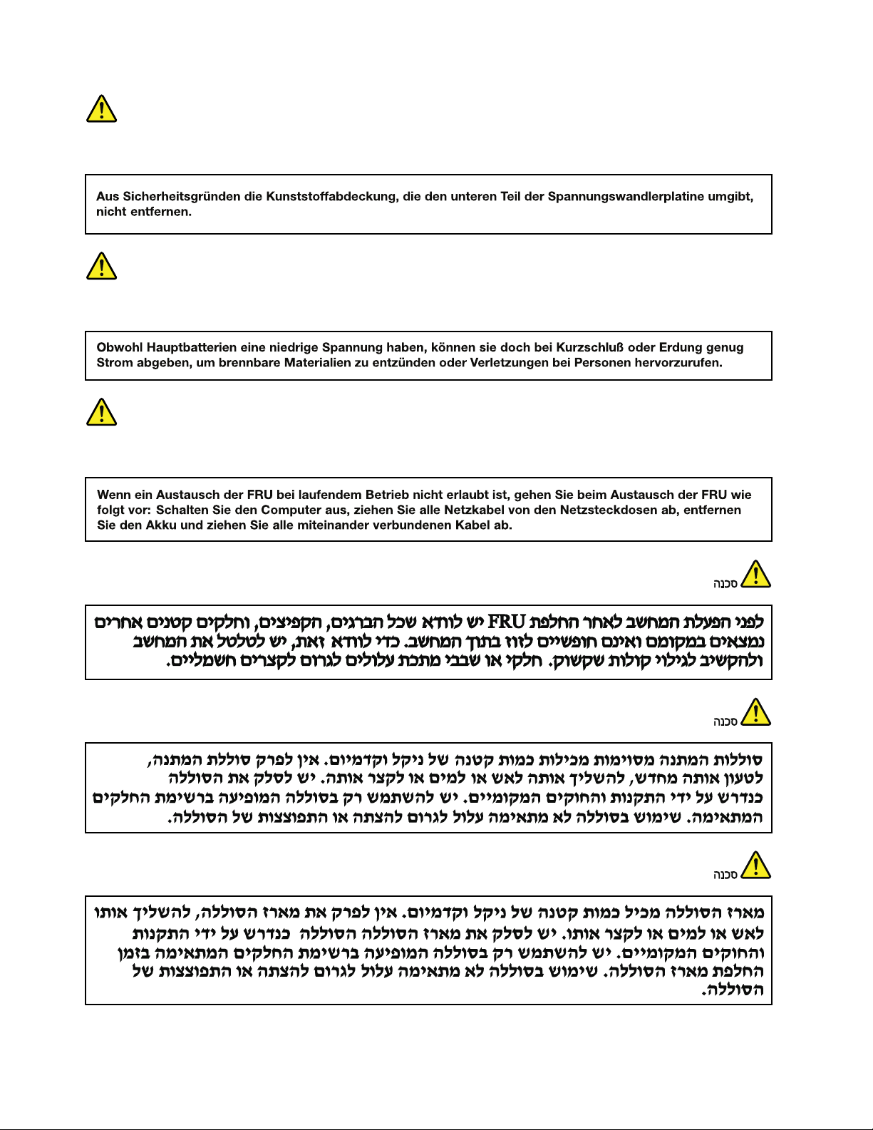
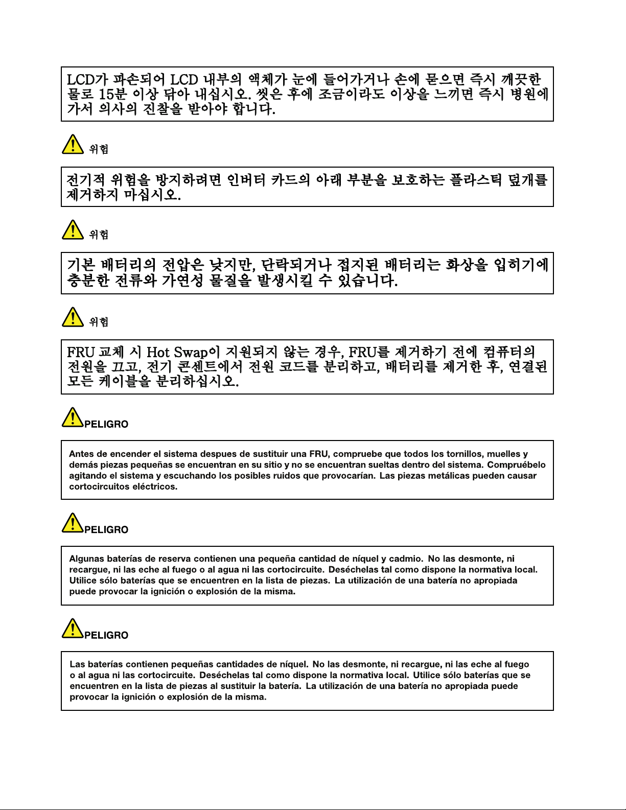
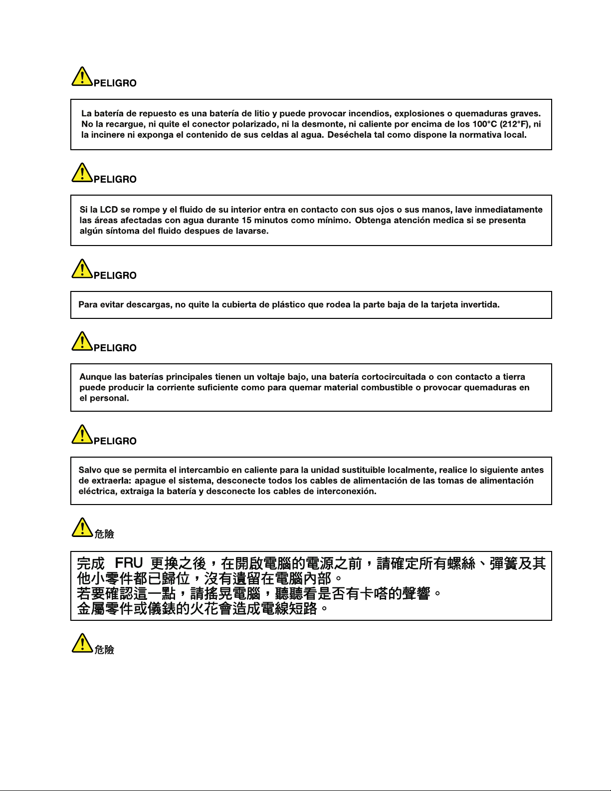
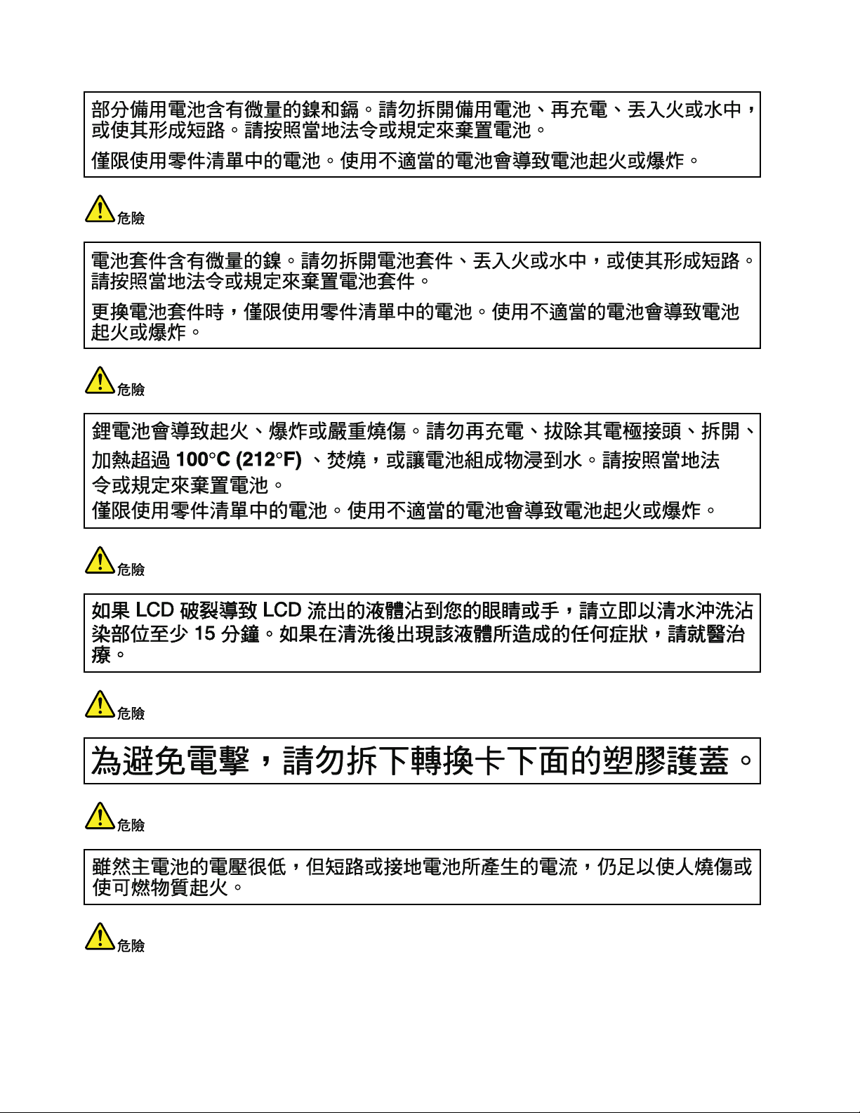
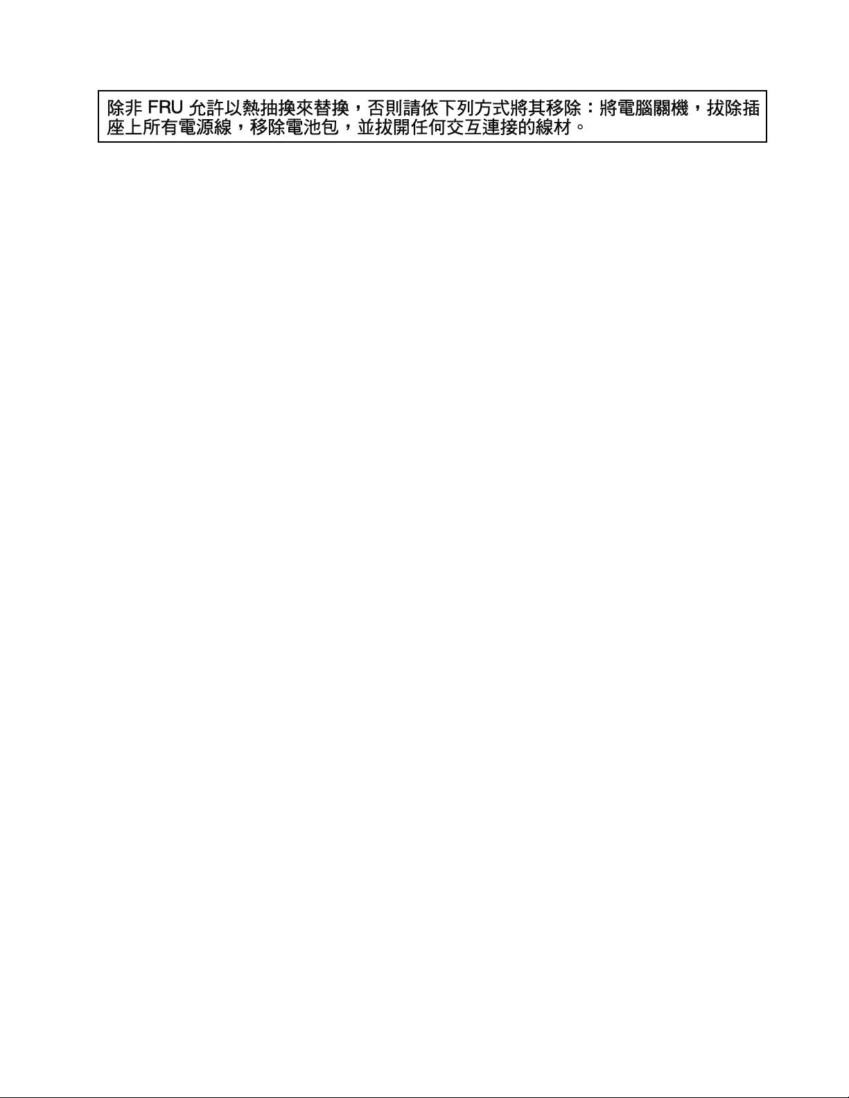
Safetynotices(multilingualtranslations)
Thesafetynoticesinthissectionareprovidedinthefollowinglanguages:
•English
•Arabic
•BrazilianPortuguese
•French
•German
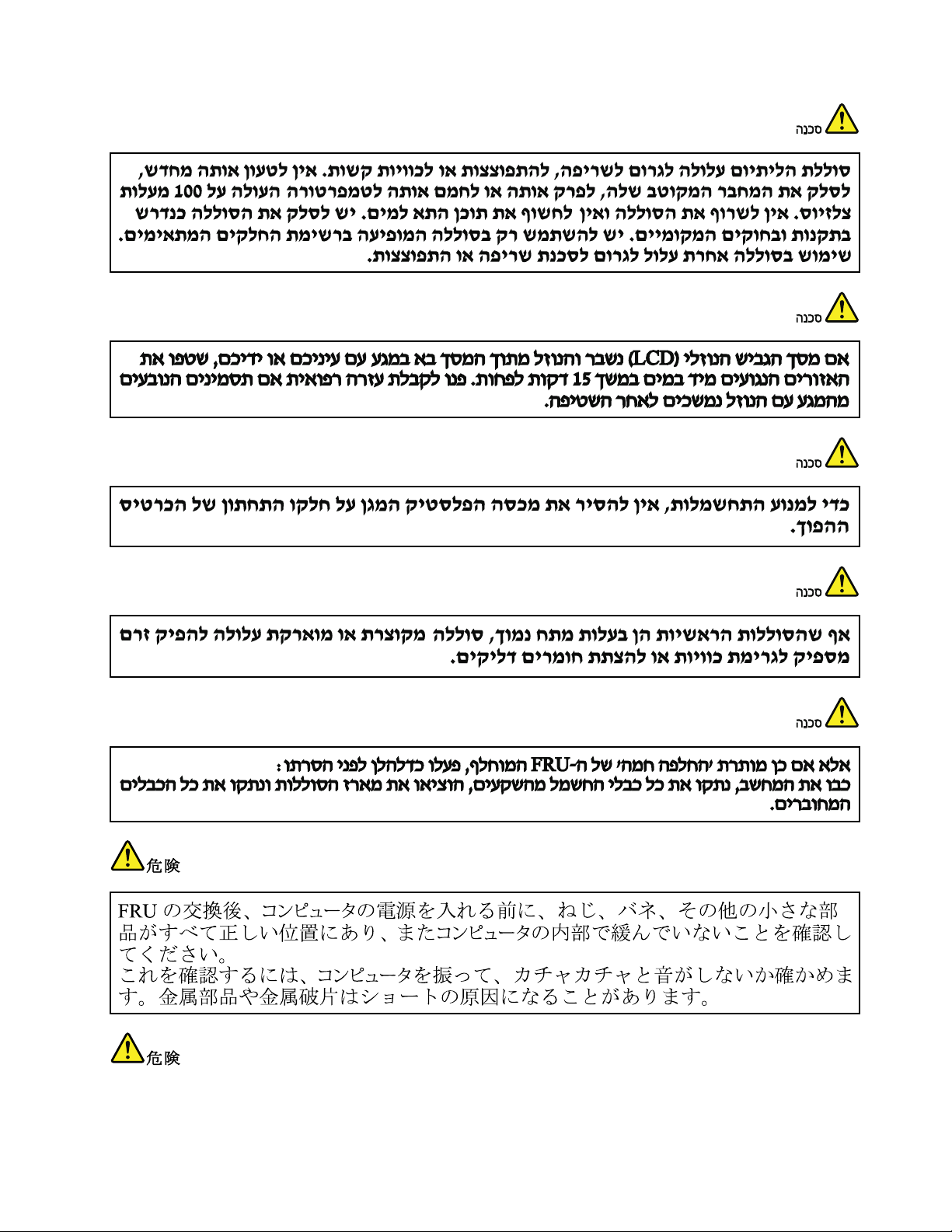
•Hebrew
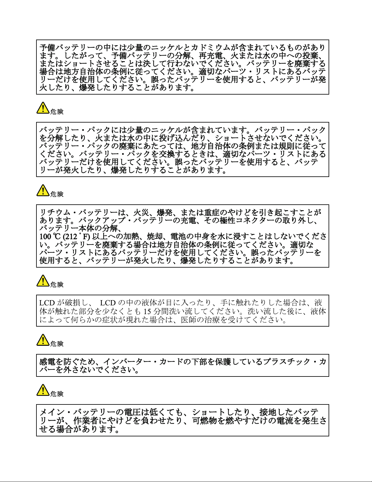
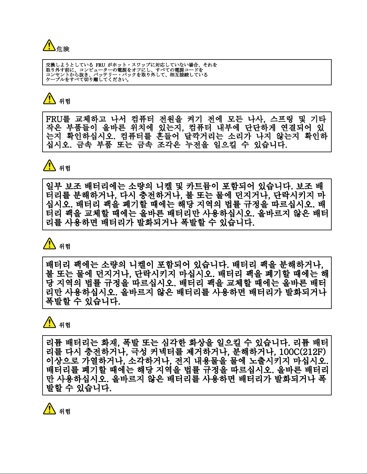
•Japanese
•Korean
•Spanish
•T raditionalChinese
DANGER
DANGER
4HardwareMaintenanceManual
Page 11
DANGER
DANGER
DANGER
DANGER
DANGER
Chapter1.Safetyinformation5
Page 12
DANGER
6HardwareMaintenanceManual
Page 13
Chapter1.Safetyinformation7
Page 14
PERIGO
PERIGO
PERIGO
PERIGO
PERIGO
PERIGO
8HardwareMaintenanceManual
Page 15
PERIGO
PERIGO
DANGER
DANGER
DANGER
Chapter1.Safetyinformation9
Page 16
DANGER
DANGER
DANGER
DANGER
DANGER
VORSICHT
10HardwareMaintenanceManual
Page 17
VORSICHT
VORSICHT
VORSICHT
VORSICHT
Chapter1.Safetyinformation11
Page 18
VORSICHT
VORSICHT
VORSICHT
12HardwareMaintenanceManual
Page 19
Chapter1.Safetyinformation13
Page 20
14HardwareMaintenanceManual
Page 21
Chapter1.Safetyinformation15
Page 22
16HardwareMaintenanceManual
Page 23
Chapter1.Safetyinformation17
Page 24
18HardwareMaintenanceManual
Page 25
Chapter1.Safetyinformation19
Page 26

20HardwareMaintenanceManual
Page 27

Chapter2.Generalcheckout
Thischaptercontainsthefollowingtopics:
•“Whattodorst”onpage21
•“Powersystemcheckout”onpage22
Beforeyougotothecheckoutinstructions,ensurethatyoureadthefollowingimportantnotes.
Importantnotes:
•Onlycertiedtrainedpersonnelshouldservicethecomputer.
•BeforereplacinganyFRU,readtheentirepageonremovingandreplacingFRUs.
•WhenyoureplaceFRUs,itisrecommendedtousenewnylon-coatedscrews.
•Beextremelycarefulduringsuchwriteoperationsascopying,saving,orformatting.Drivesinthecomputer
thatyouareservicingsequencemighthavebeenaltered.Ifyouselectanincorrectdrive,dataorprograms
mightbeoverwritten.
•ReplaceaFRUonlywithanotherFRUofthecorrectmodel.WhenyoureplaceaFRU,makesurethatthemodel
ofthemachineandtheFRUpartnumberarecorrectbyreferringtotheFRUpartslist.
•AFRUshouldnotbereplacedbecauseofasingle,unreproduciblefailure.Singlefailurescanoccurfora
varietyofreasonsthathavenothingtodowithahardwaredefect,suchascosmicradiation,electrostaticdischarge,
orsoftwareerrors.ConsiderreplacingaFRUonlywhenaproblemrecurs.IfyoususpectthataFRUisdefective,
cleartheerrorlogandrunthetestagain.Iftheerrordoesnotrecur,donotreplacetheFRU.
•BecarefulnottoreplaceanondefectiveFRU.
Whattodorst
WhenyoudoreturnaFRU,youmustincludethefollowinginformationinthepartsexchangeformor
partsreturnformthatyouattachtoit:
•Nameandphonenumberoftheservicetechnician
•Dateofservice
•Dateonwhichthemachinefailed
•Dateofpurchase
•ProcedureindexandnumberofthepageonwhichthefailingFRUwasdetected
•NameandpartnumberofthefailingFRU
•Machinetype,modelnumber,andserialnumber
•Nameandaddressofthecustomer
Note:Duringthewarrantyperiod,thecustomermayberesponsibleforrepaircostsifthecomputerdamage
wascausedbymisuse,accident,modication,unsuitablephysicaloroperatingenvironment,orimproper
maintenancebythecustomer.Followingisalistofsomecommonitemsthatarenotcoveredunderwarranty
andsomesymptomsthatmightindicatethatthesystemwassubjectedtostressbeyondnormaluse.
Beforecheckingproblemswiththecomputer,determinewhetherthedamageiscoveredunderthewarranty
byreferringtothefollowinglist:
Thefollowingarenotcoveredunderwarranty:
•LCDpanelcrackedfromtheapplicationofexcessiveforceorfrombeingdropped
•Scratched(cosmetic)parts
•Distortion,deformation,ordiscolorationofthecosmeticparts
•Plasticparts,latches,pins,orconnectorsthathavebeencrackedorbrokenbyexcessiveforce
•Damagecausedbytheliquidspilledintothecomputer
•DamagecausedbytheimproperinsertionofaPCcardortheinstallationofanincompatiblecard
©CopyrightLenovo2013
21
Page 28
•Improperdiscinsertionoruseofanopticaldrive
(20V)
1
3
2
•Diskettedrivedamagecausedbypressureonthediskettedrivecover,foreignmaterialinthedrive,
ortheinsertionofadiskettewithmultiplelabels
•Damagedorbentdisketteejectbutton
•Fusesblownbyattachmentofanunsupporteddevice
•Forgottencomputerpassword(makingthecomputerunusable)
•Stickykeyscausedbyspillingliquidontothekeyboard
•Useofanincorrectacpoweradapteronnotebookcomputers
Thefollowingsymptomsmightindicatedamagecausedbynonwarrantedactivities:
•Missingpartsmightbeasymptomofunauthorizedserviceormodication.
•Ifthespindleofaharddiskdrivebecomesnoisy,itmayhavebeensubjectedtoexcessiveforce,
ordropped.
Powersystemcheckout
Toverifyapowersymptom,dothefollowing:
1.Turnoffthecomputer.
2.Removethebatterypack.
3.Connecttheacpoweradapter.
4.Checkthatpowerissuppliedwhenyouturnonthecomputer.
5.Turnoffthecomputer.
6.Disconnecttheacpoweradapterandinstallthechargedbatterypack.
7.Checkthatthebatterypacksuppliespowerwhenyouturnonthecomputer.
Ifyoususpectapowerproblem,refertothefollowingtopicsforacheckout:
•“Checkingtheacpoweradapter”onpage22
•“Checkingoperationalcharging”onpage23
•“Checkingthebatterypack”onpage23
Checkingtheacpoweradapter
Ifthecomputerfailsonlywhentheacpoweradapterisused,refertotheinformationinthistopictocheck
theacpoweradapter.
•Ifthepower-onindicatordoesnotturnon,checkthepowercordoftheacpoweradapterforcorrect
continuityandinstallation.
•Ifthecomputerdoesnotchargeduringoperation,goto“Checkingoperationalcharging”onpage23
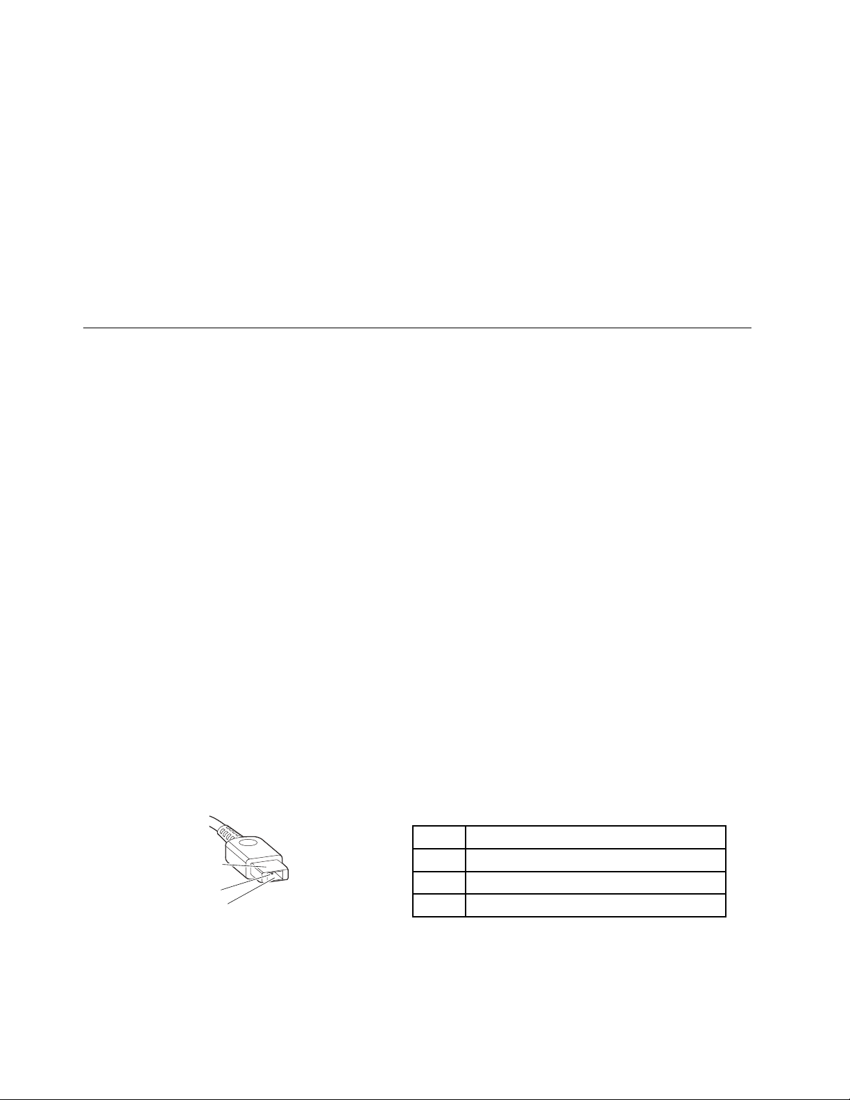
Tochecktheacpoweradapter,dothefollowing:
1.Unplugtheacpoweradaptercablefromthecomputer.
2.Measuretheoutputvoltageacrosstheplugoftheacpoweradaptercable.Thecorrectvoltagesare
showninthefollowingtable.
Pin
1+20
20
3
Voltage(Vdc)
Ground
.
Note:Theoutputvoltageacrosspin2mightdifferfromthevoltagethatyoumeasure.
3.Dependingonthevoltagethatyoumeasure,dooneofthefollowing:
•Ifthevoltageisnotcorrect,replacetheacpoweradapter.
22HardwareMaintenanceManual
Page 29
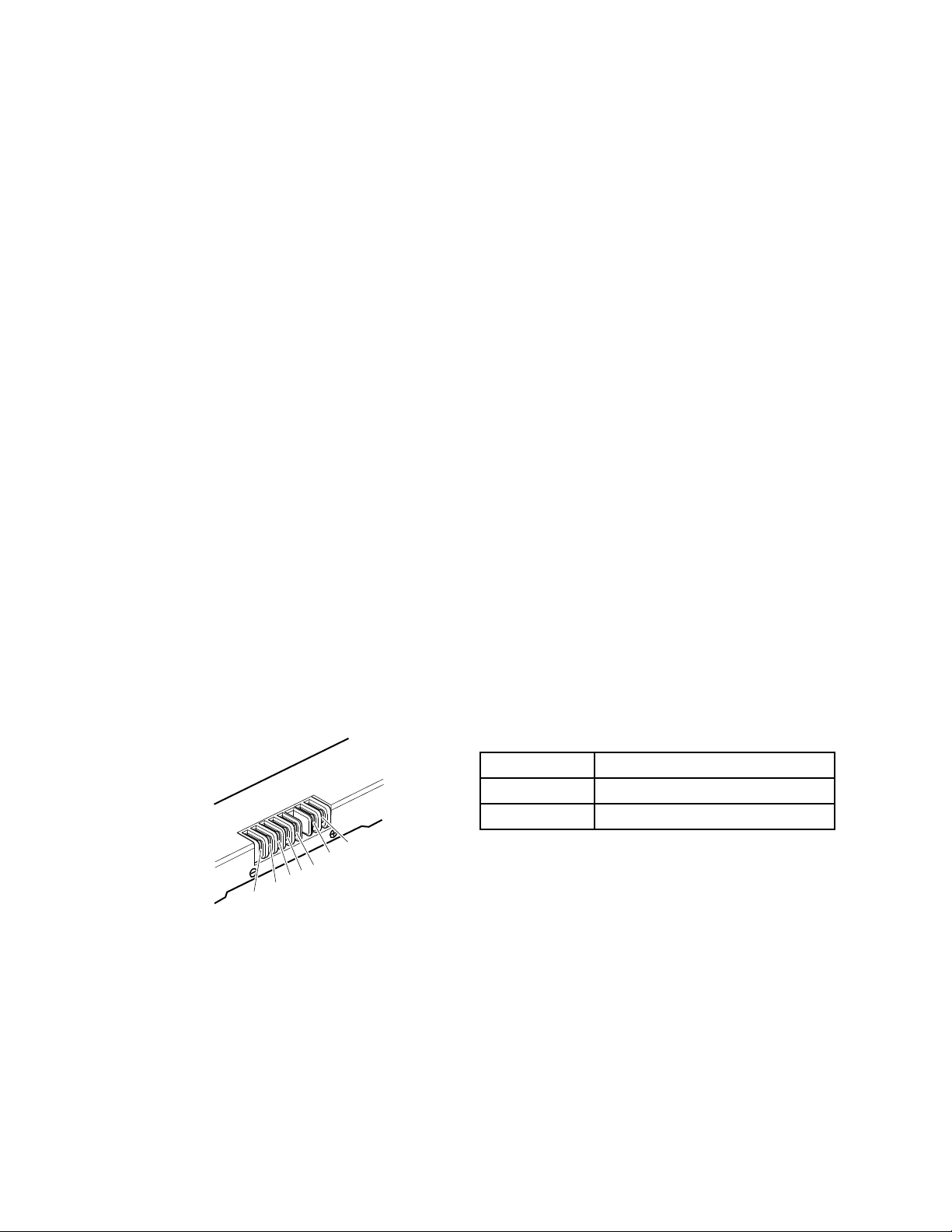
•Ifthevoltageisacceptable,dothefollowing:
1(+)
2(+)
5
4
3
6(-)
7(-)
a.Replacethesystemboard.
b.Iftheproblempersists,calltheCustomerSupportCenter.
Note:Noisefromtheacpoweradapterdoesnotalwaysindicateadefect.
Checkingoperationalcharging
Tocheckwhetherthebatterypackchargesproperlyduringoperation,dothefollowing:
Note:Beforeyoubegin,installadischargedbatterypackorabatterypackthathaslessthan50%ofthe
totalpowerremaininginthecomputer.
1.Ifthebatterystatusindicatordoesnotturnon,removethebatterypackandletitreturntoroom
temperature.
2.Reinstallthebatterypack.
3.Iftheindicatorstilldoesnotturnon,replacethebatterypack.
4.Iftheindicatorstilldoesnotturnon,replacethesystemboard.Otherwise,referto“Checkingthebattery
pack”onpage23tochecktheoriginalbatterypack.
Checkingthebatterypack
ThebatterystatusiconintheMicrosoft
®
Windows
powerremaining.
TocheckdetailedbatterystatusinformationontheWindowsoperatingsystems,dooneofthefollowing:
®
noticationareadisplaysthepercentageofbattery
•ClickStart➙LenovoSolutionCenter➙System➙Battery.
•LaunchtheLenovoSettingsprogramfromtheStartscreen,andthenclickPower.
Tocheckthebatterypack,dothefollowing:
1.Turnoffthecomputeranddisconnecttheacpoweradapter.
2.Removethebatterypackandmeasurethevoltagebetweenbatteryterminals1(+)and7(-).The
correctvoltagesareshowninthefollowingtable.
Terminal
1+0to+14
7
Voltage(Vdc)
Ground(-)
3.Measuretheresistancebetweenbatteryterminals5and7.Theresistanceshouldbe4to30KΩ.Ifthe
resistanceisnotcorrect,replacethebatterypack.
4.Dependingonthevoltagethatyoumeasure,dooneofthefollowing:
•Ifthevoltageislessthan+12.0Vdc,rechargethebatterypack.Ifthevoltagestillislessthan+12.0V
dcafterrecharging,replacethebatterypack.
•Ifthevoltageismorethan+12.0Vdc,dischargethebatterypackuntilthevoltagebecomesless
than+12.0Vdcandthenrechargethebatterypack.Ifthevoltagestillislessthan+12.0Vdcafter
recharging,replacethebatterypack.
Note:Rechargingwilltakeatleastthreehours,evenifthebatterystatusindicatordoesnotturnon.
Chapter2.Generalcheckout23
Page 30

5.Replacethesystemboardifthenewbatterypackisnotcharged.
24HardwareMaintenanceManual
Page 31

Chapter3.Importantserviceinformation
Thischapterpresentsthefollowinginformation:
•“Recoveringthecomputersettings”onpage25
•“Usingpasswords”onpage25
•“Powermanagement”onpage25
Recoveringthecomputersettings
Thistopicprovidesinformationabouttherecoveryprogramsthatareavailableforyoutorecoverthe
computersettings.
ThepreinstalledWindowsrecoveryprogramenablesyoutodothefollowing:
•Refreshingthecomputerwithoutlosingpersonalles
•Restoringthecomputertothefactorydefaultsettings
Attention:WhenyouusetheWindowsrecoveryprogramtorestorethecomputersettings,allthedata
youhavestoredontheharddiskdrivewillbedeletedandthecomputerwillberestoredtothefactory
defaultsettings.T oavoiddataloss,backupyourdatainadvance.
•Conguringtheadvancedstartupoptions
Theadvancedstartupoptionsenableyoutodothefollowing:
–ChangingthestartupsettingsoftheWindowsoperatingsystem
–RestoringtheWindowsoperatingsystemfromasystemimage
–Startingupfromanexternaldevice
Formoreinformationabouttherecoverysolutions,refertothehelpinformationsystemoftheprograms.
Usingpasswords
Youcansetthefollowingtypesofpasswordstoprotectunauthorizedaccesstoyourcomputer.
Attention:Ifyouforgetthepassword,thereisnoserviceproceduretoresetthepassword.Thesystem
boardmustbereplacedforascheduledfee.
•Power-onpassword:Apower-onpasswordprotectsthecomputerfrombeingturnedonbyan
unauthorizedperson.Ifapower-onpasswordhasbeenset,theusermustenterthepasswordbefore
startingtheoperatingsystem.
•Supervisorpassword:AsupervisorpasswordprotectsthesysteminformationstoredintheBIOS
program.TheusermustenterthesupervisorpasswordtogetaccesstotheBIOSprogramandchange
systemcongurations.
Ifyouhavesetapassword,youwillbepromptedtoenterthepasswordwheneveryouturnonthecomputer.
Powermanagement
Therearethreepowermanagementmodestoreducepowerconsumption:screenblank,sleep,and
hibernation.
©CopyrightLenovo2013
25
Page 32

Screenblankmode
Inthefollowingcircumstances,thecomputerentersscreenblankmode:
•Thetimesetonthe“Turnoffmonitor”timerontheWindows7operatingsystemexpires.
Toendscreenblankmodeandresumenormaloperation,pressanykey.
•Y ouhavepressedFn+F2.
Toendscreenblankmodeandresumenormaloperation,pressFn+F2.
Sleepmode
Whenthecomputerenterssleepmode,thefollowingeventsoccurinadditiontowhatoccursinscreen
blankmode:
•TheLCDispoweredoff.
•Theharddiskdriveispoweredoff.
•Themicroprocessorstops.
Toentersleepmode,pressFn+F1.
Incertaincircumstances,thecomputerautomaticallyenterssleepmode:
•A“suspendtime”hasbeensetonthetimer,andtheuserdoesnotdoanyoperationwiththekeyboard,
theharddiskdrive,theparallelconnector,orthediskettedrivewithinthattime.
•Thebatterystatusindicatorblinksorange,indicatingthatthebatterypowerislow.
Tocausethecomputertoreturnfromsleepmodeandresumetheoperation,dooneofthefollowing:
•PresstheFnkey.
•OpentheLCDcover.
•Pressthepowerbutton.
Also,whenthetimesetontheresumetimerelapses,thecomputerautomaticallyreturnsfromsleepmode
andresumesoperation.
Note:Thecomputerdoesnotacceptanyinputimmediatelyafteritenterssleepmode.Waitafewseconds
beforetakinganyactionstoreenteroperationmode.
Hibernationmode
Inhibernationmode,thefollowingoccurs:
•Thesystemstatus,RAM,VRAM,andsetupdataarestoredontheharddiskdrive.
•Thesystemispoweredoff.
Ifyouhavedenedoneofthefollowingactionsastheeventthatcausesthecomputertoenterhibernation
mode,performthataction.
•Closingthelid.
•Pressingthepowerbutton.
Also,thecomputerautomaticallyentershibernationmodeineitherofthefollowingcircumstances:
•A“hibernationtime”hasbeensetonthetimer,andtheuserdoesnotdoanyoperationwiththekeyboard,
theharddiskdrive,theparallelconnector,orthediskettedrivewithinthattime.
•Thetimerconditionsaresatisedinsuspendmode.
26HardwareMaintenanceManual
Page 33

Whenthepoweristurnedon,thecomputerreturnsfromhibernationmodeandresumesoperation.The
hibernationleinthebootrecordontheharddiskdriveisread,andthesystemstatusisrestoredfromthe
harddiskdrive.
Chapter3.Importantserviceinformation27
Page 34

28HardwareMaintenanceManual
Page 35

Chapter4.Statusindicators
123
Thistopicpresentsthesystemstatusindicatorsthatshowthestatusofthecomputer.
Table1.Statusindicators
IndicatorMeaning
1
ActiveProtection
™
2
3
System
indicator
Deviceaccess
statusindicator
Batterystatus
indicator
status
YourcomputermightcomewithanAPSstatusindicator.Whenthisindicatorison,
theAPSisenabled.
Whenthisindicatorison,theharddiskdriveorthesolid-statedriveisreadingorwriting
data.
Attention:
•Whentheindicatorison,donotputthecomputerintosleepmodeorturnoffthe
computer.
•Whentheindicatorison,donotmovethecomputer.Suddenphysicalshockmight
causedriveerrors.
•Solidgreen:Thebatterychargelevelisbetween80%and100%,orthebattery
dischargelevelisbetween20%and100%.
•Slowblinkinggreen:Thebatterychargelevelisbetween20%and80%,and
chargingiscontinuing.
•Slowblinkingorange:Thebatterychargelevelisbetween5%and20%,and
chargingiscontinuing.
•Solidorange:Thebatterydischargelevelisbetween5%and20%.
•Fastblinkingorange:Thebatterychargeordischargelevelis5%orless.
•Off:Thebatteryisdetachedorthecomputeristurnedoff.
©CopyrightLenovo2013
29
Page 36

30HardwareMaintenanceManual
Page 37

Chapter5.Fnkeycombinations
ThefollowingtabledescribesthefunctionsofFnkeycombinations.
Table2.Functionkeycombinations
KeycombinationDescription
Fn+Esc
Fn+SpaceEnablesordisablesthekeyboardlight.(?)
Fn+F1Putsthecomputerintosleepmode.T oresumenormaloperation,press
Fn+F2
Fn+F3
Fn+F5
Fn+F6
Fn+F8Enablesordisablesthenumerickeypad.
Fn+F9
Fn+F10
Fn+F11Multimediacontrol:Previoustrackorscene
Fn+F12Multimediacontrol:Nexttrackorscene
Fn+PgUp
Fn+PrtScHasthesamefunctionastheSysRqkeyonaconventionalkeyboard.
Fn+Home
Fn+End
Fn+PgDn
Fn+up/downarrow
Fn+left/rightarrow
Turnsonoroffthecamera.
theFnkeyonly.
Enablesthebacklightfeatureofthecomputerscreen.Todisablethefeature,
pressFn+F2.
Switchesbetweenthecomputerdisplayandanexternalmonitor.
Note:Y oualsocanusetheWindows+Pcombinationtoswitchbetweenthe
computerdisplayandanexternalmonitor.
Enablesordisablesthebuilt-inwirelessnetworkingfeatures.
Enablesordisablesthetouchpadfunction.
Multimediacontrol:Play/Pause
Multimediacontrol:Stop
HasthesamefunctionastheScrLkkeyonaconventionalkeyboard.
HasthesamefunctionasthePausekeyonaconventionalkeyboard.
HasthesamefunctionastheBreakkeyonaconventionalkeyboard.
HasthesamefunctionastheInsertkeyonaconventionalkeyboard.
Increasesordecreasesthedisplaybrightnesslevel.
Decreasesorincreasesthesoundvolume.
©CopyrightLenovo2013
31
Page 38

32HardwareMaintenanceManual
Page 39

Chapter6.Locations
1
2
2
3
8
9
11
12
10
4567
Thischapterprovidesinformationaboutcomponentlocations.
Locatingcomputercontrols,connectors,andindicators
Thistopicintroducesthelocationsofthecomputercontrols,connectors,andindicators.
Frontview
Figure1.Frontview
1Camera
2Microphones8Fingerprintreader
3Powerbutton9Right-clickbutton
4USB3.0connector
5HDMIconnector
6Comboaudiojack12Statusindicators
Note:Forthedescriptionofeachstatusindicator,seeChapter4“Statusindicators”onpage29.
©CopyrightLenovo2013
7Mediacardreaderslot
10T ouchpad
11Left-clickbutton
33
Page 40

Bottomview
1
2
Figure2.Bottomview
1Speakers
2Integratedbattery
Note:Thememorymodules,harddiskdrive,andwirelesscardsarelocatedunderneaththebottomslot
cover.
LocatingFRUsandCRUs
Thistopicintroducesthefollowingserviceparts:
•“MajorFRUsandCRUs”onpage35
•“LCDFRUsandCRUs”onpage36
Notes:
•EachFRUisavailableforalltypesormodels,unlessotherwisespecied.
•Acustomerreplaceableunit(CRU)isidentiedbyasingleasterisk(*)ortwoasterisks(**)intheCRUIDcolumn.
Asingleasterisk(*)meansthatthepartisaSelf-serviceCRU;twoasterisks(**)meansthatthepartisan
Optional-serviceCRU.ALetter“N”intheCRUIDcolumnmeansthatthepartisnotaCRU.
•CRUstatementforcustomers:
Youcanresolvesomeproblemswithyourproductwithareplacementpartyoucaninstallyourself,calleda
“CustomerReplaceableUnit”or“CRU.”SomeCRUsaredesignatedasself-serviceCRUsandothersare
designatedasoptional-serviceCRUs.Installationofself-serviceCRUsisyourresponsibility.Foroptional-service
CRUs,youcaneitherinstalltheCRUyourselforyoucanrequestthataServiceProviderinstalltheCRUaccording
tothewarrantyserviceforyourproduct.IfyouintendoninstallingtheCRU,LenovowillshiptheCRUtoyou.CRU
informationandreplacementinstructionsareshippedwithyourproductandareavailablefromLenovoatanytime
uponrequest.YoucanndalistofCRUsforyourproductinthisHardwareMaintenanceManual.Anelectronic
versionofthismanualcanbefoundathttp://www.lenovo.com/UserManuals.Followtheon-screeninstructionsto
ndthemanualforyourproduct.YoumightberequiredtoreturnthedefectiveCRU.Whenreturnisrequired:(1)
returninstructions,aprepaidshippinglabel,andacontainerwillbeincludedwiththereplacementCRU;and(2)you
mightbechargedforthereplacementCRUifLenovodoesnotreceivethedefectiveCRUwithinthirty(30)daysof
yourreceiptofthereplacementCRU.SeeyourLenovoLimitedWarrantydocumentationforfulldetails.
LenovocomputerscontainthefollowingtypesofCRUs:
–Self-serviceCRUs:TheseCRUsunplugorareheldbynomorethantwoscrews.Examplesofthesetypes
ofCRUsincludetheacpoweradapter,powercord,battery,andharddiskdrive.Otherself-serviceCRUs
dependingonproductdesignmightincludethememorymodule,wirelesscard,keyboard,andpalmrest
withngerprintreaderandtouchpad.
34HardwareMaintenanceManual
Page 41

–Optional-serviceCRUs:TheseCRUsareisolatedpartswithinthecomputerthatareconcealedbyanaccess
13
14
15
16
17
18
19
20
12
11
1
2
3
4
5
6
7
8
9
10
panelthatistypicallysecuredbymorethantwoscrews.Oncetheaccesspanelisremoved,thespecic
CRUisvisible.
MajorFRUsandCRUs
Table3.MajorFRUsandCRUs
No.FRUdescription
1
2
3
49
5
6
7
8
10
11
LCDunit
KeyboardbezelassemblywithkeyboardN
FingerprintreaderassemblyN
HallsensorsN
ThermalModuleassemblyN
I/Oboard
MediacardreaderboardN
Harddiskdriveorsolid-statedriveN
BatterypackN
BasecoverN
Chapter6.Locations35
CRUID
N
N
Page 42

Table3.MajorFRUsandCRUs(continued)
1
3
4
5
2
7
6
8
No.FRUdescription
12
13
14
15
16
17
18
19
20
Speakers
WirelessLANcardN
M.2solid-statedriveN
MemorymoduleN
Systemboard
BackupbatteryN
TouchpadandtouchpadbracketN
LEDboardN
LenovoOneLinkconnectorcover
LCDFRUsandCRUs
LenovoM4400smodelsusea356-cm(14.0-inch),high-denition(HD),light-emittingdiode(LED),liquid
crystaldisplay(LCD).
CRUID
N
N
N
36HardwareMaintenanceManual
Page 43

Table4.LCDFRUs
No.FRUdescription
1
2
3
4
5
6
7
8
LCDBezel
Cameraandmicrophonesboard
HingesN
AntennasN
LCDcover
LCDcable
LCDpanel
LCDbezel
CRUID
N
N
N
N
N
N
LookingupFRUinformation
FordetailedFRUinformation,includingpartnumbers,descriptions,andsubstitutionpartnumbers,goto
http://www.lenovo.com/serviceparts-lookup.
Chapter6.Locations37
Page 44

38HardwareMaintenanceManual
Page 45

Chapter7.FRUreplacementnotices
Thischapterpresentsnoticesrelatedtoremovingandreplacingparts.Readthischaptercarefullybefore
replacinganyFRU.
CRUstatementforcustomers:
Youcanresolvesomeproblemswithyourproductwithareplacementpartyoucaninstallyourself,called
a“CustomerReplaceableUnit”or“CRU.”SomeCRUsaredesignatedasself-serviceCRUsandothers
aredesignatedasoptional-serviceCRUs.Installationofself-serviceCRUsisyourresponsibility.For
optional-serviceCRUs,youcaneitherinstalltheCRUyourselforyoucanrequestthataServiceProvider
installtheCRUaccordingtothewarrantyserviceforyourproduct.IfyouintendoninstallingtheCRU,
LenovowillshiptheCRUtoyou.CRUinformationandreplacementinstructionsareshippedwithyour
productandareavailablefromLenovoatanytimeuponrequest.YoucanndalistofCRUsforyour
productinthisHardwareMaintenanceManual.Anelectronicversionofthismanualcanbefoundat
http://www.lenovo.com/UserManuals.Followtheon-screeninstructionstondthemanualforyourproduct.
YoumightberequiredtoreturnthedefectiveCRU.Whenreturnisrequired:(1)returninstructions,aprepaid
shippinglabel,andacontainerwillbeincludedwiththereplacementCRU;and(2)youmightbechargedfor
thereplacementCRUifLenovodoesnotreceivethedefectiveCRUwithinthirty(30)daysofyourreceiptof
thereplacementCRU.SeeyourLenovoLimitedWarrantydocumentationforfulldetails.
ImportantnoticeforreplacingFRUs
EnsurethatthecomputerhasthelatestBIOSversionanddevicedriversinstalledbeforereplacinganyFRUs.
Afteryoureplaceasystemboard,ensurethatyouinstallthelatestBIOSversiononthenewsystemboard.
Note:BIOSanddevicedriversarecustomer-installable.TheBIOSanddevicedriversareavailableat
http://www.lenovo.com/support.
TodownloadthelatestBIOS,devicedrivers,andothersoftwareprograms,dothefollowing:
1.Gotohttp://www.lenovo.com/support.
2.ClickDownloadDrivers&Software.TheWebsiteoffersthreeoptionstobeginyoursearch:
•Searchbyproductnumber
•Searchthroughtheproductauto-detectfunction
•Searchbyproductcategory
3.Followtheinstructionsonthescreenandinstallthenecessarysoftware.
4.Restartthecomputer.
Notes:YoualsocanimprovethecomputerperformancebyupdatingtheBIOSutilitytothelatestversion
fromtheLenovoSupportWebsitehttp://www.lenovo.com/support.
•Beforeinstallingthelatestutility,makesurethatthebatteryisfullychargedandanacpoweradapteris
connected.
•DonottrytoupdatetheBIOSsettingsforanycomputerunlessyouhavebeentrainedandcertied.An
untrainedpersonrunstheriskofdamagingthecomputer.
•Donotturnofforputyourcomputerintosleeporhibernationuntiltheupdatehasbeencompleted.
Otherwise,thesystemboardmightbedamaged.
WhenyouarereplacingandservicingFRUs,refertothefollowinginstructionstoavoidunnecessaryexpense:
©CopyrightLenovo2013
39
Page 46

•IfyouareinstructedtoreplaceaFRUbutthereplacementdoesnotsolvetheproblem,reinstallthe
originalFRUbeforeyoucontinue.
•Somecomputershavebothaprocessorboardandasystemboard.Ifyouareinstructedtoreplaceeither
theprocessorboardorthesystemboard,butthereplacementdoesnotsolvetheproblem,reinstallthe
originalboard,andthenreplacetheotherone.
•IfanadapteroradeviceconsistsofmorethanoneFRU,anyoftheFRUsmightbethecauseoftheerror.
Beforereplacingtheadapterordevice,removetheFRUsonebyonetoseeifthesymptomschange.Find
andreplaceonlytheFRUthatchangedthesymptoms.
Screwnotices
TheLenovonotebookcomputerusesspecialnylon-coatedscrewsthathavethefollowingcharacteristics:
•Theymaintaintightconnections.
•Theydonoteasilycomeloose,evenwithshockorvibration.
•Theyarehardertotighten.
Dothefollowingwhenyouareservicingthecomputer:
•Keepthescrewkitinyourtoolbag.
•Itisrecommendedthatyouusenewscrews.
•Itisrecommendedthatyouuseeachscrewonlyonce.
•Useatorquescrewdriverifyouhaveone.
Tightenscrewsasfollows:
•Plastictoplastic
Turnanadditionalangleof90degreesafterthescrewheadtouchesthesurfaceoftheplasticpart.
•Logiccardtoplastic
Turnanadditionalangleof180degreesafterthescrewheadtouchesthesurfaceofthelogiccard.
Notes:
•Ensurethatyouusethecorrectscrew.Itisrecommendedthatyouusenewscrewsforreplacements.If
youhaveatorquescrewdriver,rmlytightenallscrewstothetorquespeciedinthescrewinformation
tableforeachstep.
•Ensurethattorquescrewdriversarecalibratedcorrectlyfollowingcountryspecications.
40HardwareMaintenanceManual
Page 47

Chapter8.RemovingorreplacingaFRU
ThischapterprovidesinstructionsonhowtoremoveorreplaceaFRU.
CRUstatementforcustomers:
Youcanresolvesomeproblemswithyourproductwithareplacementpartyoucaninstallyourself,called
a“CustomerReplaceableUnit”or“CRU.”SomeCRUsaredesignatedasself-serviceCRUsandothers
aredesignatedasoptional-serviceCRUs.Installationofself-serviceCRUsisyourresponsibility.For
optional-serviceCRUs,youcaneitherinstalltheCRUyourselforyoucanrequestthataServiceProvider
installtheCRUaccordingtothewarrantyserviceforyourproduct.IfyouintendoninstallingtheCRU,
LenovowillshiptheCRUtoyou.CRUinformationandreplacementinstructionsareshippedwithyour
productandareavailablefromLenovoatanytimeuponrequest.YoucanndalistofCRUsforyour
productinthisHardwareMaintenanceManual.Anelectronicversionofthismanualcanbefoundat
http://www.lenovo.com/UserManuals.Followtheon-screeninstructionstondthemanualforyourproduct.
YoumightberequiredtoreturnthedefectiveCRU.Whenreturnisrequired:(1)returninstructions,aprepaid
shippinglabel,andacontainerwillbeincludedwiththereplacementCRU;and(2)youmightbechargedfor
thereplacementCRUifLenovodoesnotreceivethedefectiveCRUwithinthirty(30)daysofyourreceiptof
thereplacementCRU.SeeyourLenovoLimitedWarrantydocumentationforfulldetails.
Generalguidelines
WhenremovingorreplacingaFRU,ensurethatyouobservethefollowinggeneralguidelines:
1.Donottrytoserviceanycomputerunlessyouhavebeentrainedandcertied.Anuntrainedpersonruns
theriskofdamagingparts.
2.BeforereplacinganyFRU,reviewChapter7“FRUreplacementnotices”onpage39.
3.BeginbyremovinganyFRUsthathavetoberemovedbeforereplacingthefailingFRU.Anysuch
FRUsarelistedatthebeginningofeachFRUreplacementprocedure.Removethemintheorderin
whichtheyarelisted.
4.FollowthecorrectsequenceinthestepsforremovingaFRU,asshownintheillustrationsbythe
numbersinsquarecallouts.
5.Whenturningascrew,turnitinthedirectionasshownbythearrowintheillustration.
6.WhenremovingaFRU,moveitinthedirectionasshownbythearrowintheillustration.
7.ToinstallanewFRUinplace,reversetheremovalprocedureandfollowanynotesthatpertainto
replacement.
8.WhenreplacingaFRU,usethecorrectscrewsasshowninthereplacementprocedure.
DANGER
BeforeremovinganyFRU,turnoffthecomputer ,unplugallpowercordsfromelectricaloutlets,
removethebatterypack,andthendisconnectanyinterconnectingcables.
Attention:AfterreplacingaFRU,donotturnonthecomputeruntilyouhaveensuredthatallscrews,springs,
andothersmallpartsareinplaceandnonearelooseinsidethecomputer.Verifythisbyshakingthecomputer
gentlyandlisteningforrattlingsounds.Metallicpartsormetalakescancauseelectricalshortcircuits.
Attention:ThesystemboardissensitivetoandcanbedamagedbyESD.Beforetouchingit,establish
personalgroundingbytouchingagroundpointwithonehandorbyusinganESDstrap(P/N6405959).
©CopyrightLenovo2013
41
Page 48

1010LenovoOneLinkconnectorcover
RemovalstepsoftheLenovoOneLinkconnectorcover
Removetheconnectorcoverasshowninthefollowingillustration.
Note:EnsurethatyoureattachtheconnectorcovertotheLenovoOneLinkconnectorafternishingthe
servicing.
42HardwareMaintenanceManual
Page 49

1020Basecover
1
1
1
1
2
1
1
1
1
Removalstepsofthebasecover
Removethescrews1,andthenremovethebasecover2.
StepScrew(quantity)Color
1
M2×4.5mm,at-head,nylon-coated(8)
Black0.181Nm
Torque
(1.85kgf-cm)
Applyinglabelstothebasecover
Thenewbasecoverisshippedwithakitcontaininglabelsofseveralkinds.Applythoselabelswhenyou
replacethebasecover.Forthelabelsnotshippedwiththenewbasecover,peelthemfromtheoldbase
cover,andadherethemtothenewone.
Thefollowingillustrationshowsthelabellocationsonthebasecover.
Chapter8.RemovingorreplacingaFRU43
Page 50

1 2 3
1CECPlabel3GenuineMicrosoftlabel
2S/Nlabel
1030Batterypack
Foraccess,removethisFRU:
“1020Basecover”onpage43
RemovalstepsoftheBatterypack
DANGER
Useonlythebatteryspeciedinthepartslistforyourcomputer .Anyotherbatterycouldignite
orexplode.
44HardwareMaintenanceManual
Page 51

Disconnecttheconnector1,andthenremovethescrew2.
1
2
2
2
3
StepScrew(quantity)Color
2
M2×4mm,at-head,nylon-coated(3)
Removethebatterypack3.
Wheninstalling:Ensurethattheconnectorisrmlyattached.
1040Backupbattery
Torque
Black0.181Nm
(1.85kgf-cm)
Foraccess,removethisFRU:
“1020Basecover”onpage43
Removalstepsofthebackupbattery
DANGER
Useonlythebatteryspeciedinthepartslistforyourcomputer .Anyotherbatterycouldignite
orexplode.
Chapter8.RemovingorreplacingaFRU45
Page 52

Disconnecttheconnector1andthenremovethebackupbattery2.
1
2
2
1
1
1050Memorymodules
Foraccess,removethisFRU:
“1020Basecover”onpage43
Removalstepsofthememorymodules
Releasethetwolatchesonbothedgesofthesocketatthesametime1,andthencarefullyremovethe
memorymodule2.
Wheninstalling:Insertthenotchedendofthememorymoduleintothesocket.Pressthememorymodule
rmly,andpivotitdownwarduntilitsnapsintoplace.Ensurethatthememorymoduleisrmlyinstalled
intheslotanddoesnotmoveeasily.
46HardwareMaintenanceManual
Page 53

1060PCIExpressMiniCardforwirelessLAN
2
1
1
3
Foraccess,removethisFRU:
“1020Basecover”onpage43
RemovalstepsofthePCIExpressMiniCardforwirelessLAN
UnplugtheconnectorsbyusingtheantennaRFconnectororpickuptheconnectorswithyourngersand
gentlyunplugthem1.Thenremovethescrew2.
StepScrew(quantity)Color
2
M2×4mm,at-head,nylon-coated(1)
Black0.181Nm
Torque
(1.85kgf-cm)
RemovethePCIExpressMiniCardforwirelessLAN.
Wheninstalling:Plugtheblackcableintothemainconnector,andthewhitecableintotheauxiliary
connector.
1070M.2solid-statedrive
Foraccess,removethisFRU:
“1020Basecover”onpage43
Chapter8.RemovingorreplacingaFRU47
Page 54

Attention:
1
2
•Donotdropthedriveorapplyanyphysicalshocktoit.Thedriveissensitivetophysicalshock.Improper
handlingcancausedamageandpermanentlossofdata.
•Beforeremovingthedrive,havetheusermakeabackupcopyofalltheinformationonitifpossible.
•Neverremovethedrivewhilethecomputerisoperatingorinsuspendmode.
RemovalstepsoftheM.2solid-statedrive
Removethescrew1.
StepScrew(quantity)Color
1
M2×4mm,at-head,nylon-coated(1)
Black0.181Nm
Torque
(1.85kgf-cm)
RemovetheM.2solid-statedrive.
1080Harddiskdriveassembly
Foraccess,removethisFRU:
“1020Basecover”onpage43
48HardwareMaintenanceManual
Page 55

Importantnoticeforreplacingaharddiskdrive
1
1
1
Alwaystrytorunalow-levelformatbeforereplacingaharddiskdrive.Thiswillcauseallcustomerdataon
theharddisktobelost.Ensurethatthecustomerhasacurrentbackupofthedatabeforedoingthistask.
Attention:
•Donotdropthedriveorapplyanyphysicalshocktoit.Thedriveissensitivetophysicalshock.Improper
handlingcancausedamageandpermanentlossofdata.
•Beforeremovingthedrive,havetheusermakeabackupcopyofalltheinformationonitifpossible.
•Neverremovethedrivewhilethecomputerisoperatingorinsuspendmode.
•Thedrivestartupsequenceinthecomputeryouareservicingmighthavebeenchanged.Beextremely
carefulduringwriteoperationssuchascopying,saving,orformatting.Ifyouselectanincorrectdrive,
dataorprogramscanbeoverwritten.
Removalstepsoftheharddiskdriveassembly
Removethescrews1.
StepScrew(quantity)Color
1
M2×4mm,at-head,nylon-coated(3)
Black0.181Nm
Chapter8.RemovingorreplacingaFRU49
Torque
(1.85kgf-cm)
Page 56

Removetheharddiskdrivefromtheslot2.
2
1
1
1
1
Wheninstalling:Ensurethattheharddiskdriveconnectorisattachedrmly.
Removalstepsoftheharddiskdrivebracket
Removethescrews1.
StepScrew(quantity)Color
1
M3×3mm,at-head,nylon-coated(4)Silver
Torque
0.392Nm
(4.0kgf-cm)
50HardwareMaintenanceManual
Page 57

Removetheharddiskdrivebracket2.
2
2
1
1090Fingerprintboardbracketandngerprintboard
Foraccess,removethisFRU:
“1020Basecover”onpage43
Removalstepsofthengerprintboardbracketandngerprintboard
Removethescrew1,andthenremovethengerprintboardbracket2.
StepScrew(quantity)Color
1
M2×2.5mm,at-head,nylon-coated(1)
Black0.181Nm
Chapter8.RemovingorreplacingaFRU51
Torque
(1.85kgf-cm)
Page 58

Detachthengerprintconnector34.
3
4
5
Wheninstalling:Ensurethattheconnectorisattachedrmlytothesystemboard.
Removethengerprintboard
1100Speakerassembly
Foraccess,removetheseFRUs:
•“1020Basecover”onpage43
•“1030Batterypack”onpage44
5.
52HardwareMaintenanceManual
Page 59

Removalstepsofthespeakerassembly
2
2
1
3
3
Detachtheconnector1andthenremovethescrewsand2.
StepScrew(quantity)Color
2
M2.5×2.5mm,at-head,nylon-coated(2)
Removethespeakerassembly3.
1110T ouchpanel
Foraccess,removetheseFRUsinorder:
•“1020Basecover”onpage43
•“1030Batterypack”onpage44
Torque
Black0.392Nm
(4.0kgf-cm)
Chapter8.RemovingorreplacingaFRU53
Page 60

Removalstepsofthetouchpanel
1
1
2
3
3
3
3
1
4
Detachtheconnector12,andthenremovethescrews3.
StepScrew(quantity)Color
3
M2×3mm,at-head,nylon-coated(4)
Black0.181Nm
Wheninstalling:Ensurethattheconnectorisattachedrmlytothesystemboard.
Removethetouchpanelbracket4.
Torque
(1.85kgf-cm)
54HardwareMaintenanceManual
Page 61

Removethetouchpanel5.
1
5
1
2
1120Hallsensor
Foraccess,removetheseFRUsinorder:
•“1020Basecover”onpage43
•“1030Batterypack”onpage44
•“1100Speakerassembly”onpage52
Removalstepsofthengerprintboardbracketandngerprintboard
Removethescrew1,andthenremovethehallsensor2.
StepScrew(quantity)Color
1
M2×3mm,at-head,nylon-coated(1)
Torque
Black0.181Nm
(1.85kgf-cm)
1130Mediacardreaderslotboard
Foraccess,removetheseFRUsinorder:
Chapter8.RemovingorreplacingaFRU55
Page 62

•“1020Basecover”onpage43
1
2
3
•“1030Batterypack”onpage44
•“1100Speakerassembly”onpage52
Removalstepsofthemediacardreaderslotboard
Detachthecable1,andthendetachtheconnector23.
Wheninstalling:Ensurethatthecableisrmlyattachedtothesystemboard.
56HardwareMaintenanceManual
Page 63

Removethescrew4,andthenremovethemediacardreaderslotboard56.
4
5
0
6
7
1
1
1
2
2
StepScrew(quantity)Color
4
M2×3mm,at-head,nylon-coated(1)
1140Thermalmoduleassembly
Foraccess,removethisFRU:
“1020Basecover”onpage43
Torque
Black0.181Nm
(1.85kgf-cm)
Removalstepsofthethermalmoduleassembly
Removethecablesthatalignedonthethermalmoduleassembly.
Chapter8.RemovingorreplacingaFRU57
Page 64

Detachtheconnector3andthenloosenthescrews.
3
4a
4b
4d
4c
4e
4f
4g
4d
5
Wheninstalling:Ensurethattheconnectorisattachedrmlytothesystemboard.
Removethethermalmoduleassembly
5.
Wheninstalling:Beforeyouattachthethermalmoduleassemblytothecomputer,applythermalgrease,at
anamountof0.2grams,onthepartmarked
aandbasshowninthefollowingillustrations.Eithertoomuch
ortoolessapplicationofgreasecancauseathermalproblemduetoimperfectcontactwithacomponent.
58HardwareMaintenanceManual
Page 65
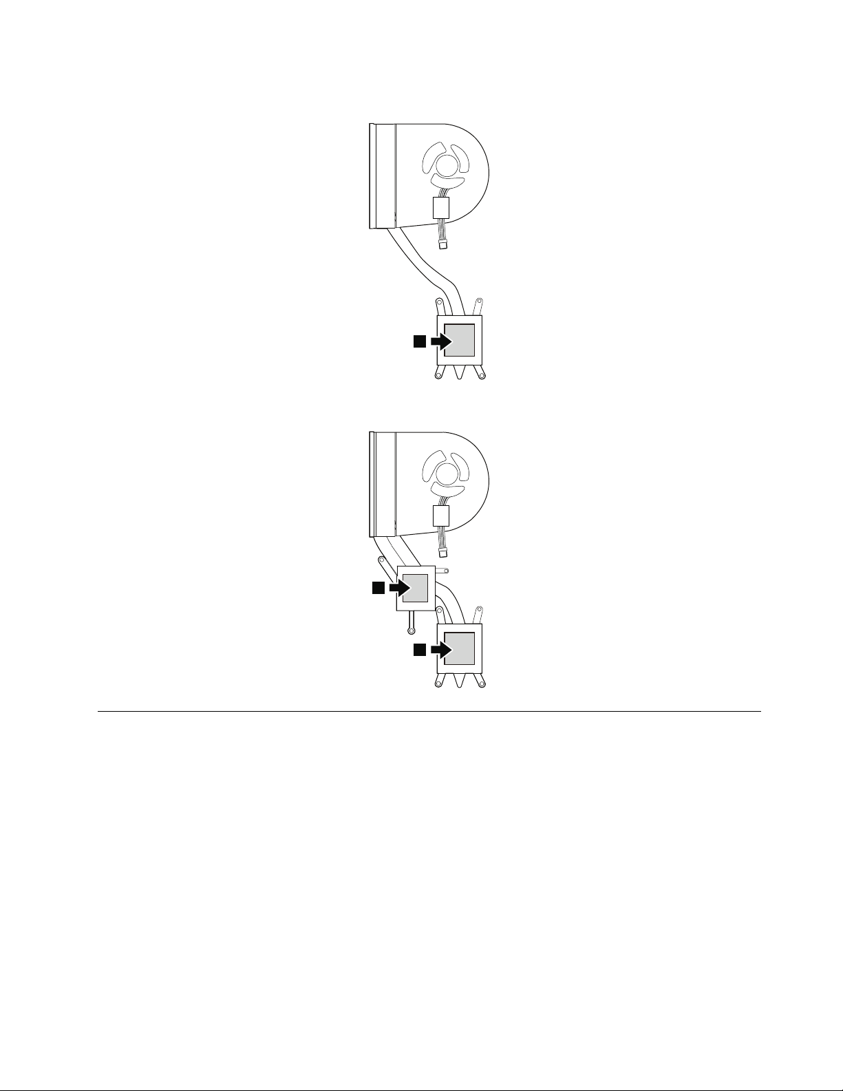
Formodelswithanintegratedthermalmoduleassembly
a
a
b
Formodelswithadiscretethermalmoduleassembly
1150Systemboardassembly
Foraccess,removetheseFRUsinorder:
•“1020Basecover”onpage43
•“1030Batterypack”onpage44
•“1080Harddiskdriveassembly”onpage48
•“1070M.2solid-statedrive”onpage47
•“1060PCIExpressMiniCardforwirelessLAN”onpage47
Importantnoticeforreplacingthesystemboard
Whenreplacingthesystemboard,observethefollowingguidelines:
•Donotdropasystemboardonabenchtopthathasahardsurface,suchasmetal,wood,orcomposite.
•Donotapplyanyexcessiveforcetoasystemboard.
•Avoidroughhandlingofanykind.
•AvoidbendingasystemboardorhardpushingtopreventcrackingateachBallGridArray(BGA)chipset.
Chapter8.RemovingorreplacingaFRU59
Page 66

•Whenyouputasystemboarddown,besuretoputitonlyonapaddedsurfacesuchasanESDmat
a
b
a
oracorrugatedconductivesurface.
Locatingmajorsensitivecomponentsonthesystemboard
Attention:Thefollowingcomponentsmountedonasystemboardareextremelysensitive.Improper
handlingofasystemboardcancausedamagetothefollowingcomponents,andmightcauseasystem
malfunction.Whenyouservicethesystemboard,avoidanykindofroughhandling.
aPlatformControllerHub(PCH)
bMicroprocessor
cGraphicschip(fordiscretegraphicsmodels)
Formodelswithanintegratedthermalmoduleassembly
Formodelswithadiscretethermalmoduleassembly
60HardwareMaintenanceManual
Page 67

Removalstepsofthesystemboardassembly
1
2
11
9
10
8
7
6
5
3
4
12
12
12
12
13
13
Detachtheconnectors.
Wheninstalling:Ensurethatalltheconnectorsarermlyattached.
Removethescrews.
StepScrew(quantity)Color
12
13
M2×4mm,at-head,nylon-coated(4)
M2×4mm,at-head,nylon-coated(2)Silver
Torque
Black0.181Nm
(1.85kgf-cm)
0.181Nm
(1.85kgf-cm)
Chapter8.RemovingorreplacingaFRU61
Page 68

Removethesystemboard.
14
1
1160I/Oboard
Foraccess,removetheseFRUsinorder:
•“1020Basecover”onpage43
•“1030Batterypack”onpage44
•“1080Harddiskdriveassembly”onpage48
RemovalstepsoftheI/Oboard
Detachtheconnector1.
Wheninstalling:Ensurethattheconnectorisattachedrmlytothesystemboard.
62HardwareMaintenanceManual
Page 69

Removethescrews2,andthenremovetheI/Oboard3.
3
2
2
1
StepScrew(quantity)Color
2
M2×4mm,at-head,nylon-coated(2)
1170Thermalsensor
Foraccess,removetheseFRUsinorder:
•“1020Basecover”onpage43
•“1030Batterypack”onpage44
•“1080Harddiskdriveassembly”onpage48
Removalstepsofthethermalsensor
Detachtheconnector1.
Torque
Black0.181Nm
(1.85kgf-cm)
Wheninstalling:Ensurethattheconnectorisrmlyattachedtothesystemboard.
Chapter8.RemovingorreplacingaFRU63
Page 70

Removethescrew2andthenremovethethermalsensor3.
2
3
1
2
StepScrew(quantity)Color
2
M2.5×5mm,at-head,nylon-coated(1)
Formodelswithnon-touchpanel
2010LCDUnit
Foraccess,removetheseFRUsinorder:
•“1020Basecover”onpage43
•“1030Batterypack”onpage44
RemovalstepsoftheLCDunit
Torque
Black0.392Nm
(4.0kgf-cm)
Wheninstalling:Ensurethattheconnectorsarermlyattached.
64HardwareMaintenanceManual
Page 71

3
3
4
4
4
3
3
3
StepScrew(quantity)Color
5
5
5
6
6
7
3
4
M2.5×5mm,at-head,nylon-coated(5)
M2.0×4mm,at-head,nylon-coated(3)
Torque
Black0.392Nm
(4.0kgf-cm)
Black0.181Nm
(1.85kgf-cm)
Wheninstalling:Ensurethatyouroutethecablesrmlyandtapeupintheproperpositions.
Chapter8.RemovingorreplacingaFRU65
Page 72

Attention:Whenyouroutethecables,ensurethattheyarenotsubjecttoanytension.Tensioncouldcause
1
0
00
2
3
thecablestobedamagedbythecableguides,orawiretobebroken.
2030T ouchcontrolboardandLCDpanel
Foraccess,removetheseFRUsinorder:
•“1020Basecover”onpage43
•“1030Batterypack”onpage44
•“2010LCDUnit”onpage64
•“2020LCDhingekit”onpage69
Removalstepsofthetouchcontrolboard
66HardwareMaintenanceManual
Page 73

5
4
0
6
7
8
Chapter8.RemovingorreplacingaFRU67
Page 74

RemovalstepsoftheLCDpanel
9
9
9
9
11
10
10
10
10
10
10
10
10
10
10
10
10
10
10
13
14
12
StepScrew(quantity)Color
9
M2×3mm,at-head,nylon-coated(4)
Torque
Black0.181Nm
(1.85kgf-cm)
68HardwareMaintenanceManual
Page 75

2020LCDhingekit
2
1
1
1
1
1
1
1
1
Foraccess,removetheseFRUsinorder:
•“1020Basecover”onpage43
•“1030Batterypack”onpage44
•“2010LCDUnit”onpage64
RemovalstepsoftheLCDhingecap
Removethescrews1.
StepScrew(quantity)Color
1
M2×4mm,at-head,nylon-coated(2)
Black0.181Nm
Torque
(1.85kgf-cm)
RemovalstepsoftheLCDhinge
Removethescrews1.
StepScrew(quantity)Color
1
M2.5×3.5mm,at-head,nylon-coated(6)
Torque
Black0.392Nm
(4.0kgf-cm)
Chapter8.RemovingorreplacingaFRU69
Page 76

2
2
2040Camera-and-microphone-combocard
Foraccess,removetheseFRUsinorder:
•“1020Basecover”onpage43
•“1030Batterypack”onpage44
•“2010LCDUnit”onpage64
•“2020LCDhingekit”onpage69
•“2030TouchcontrolboardandLCDpanel”onpage66
70HardwareMaintenanceManual
Page 77

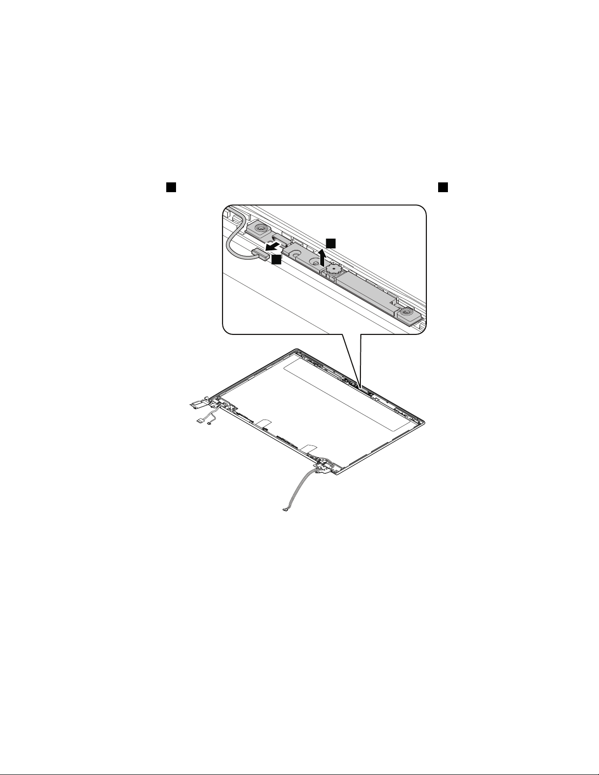
Removalstepsofthecamera-and-microphone-combocard
1
2
Detachtheconnector1andthenpeeloffthecamera-and-microphone-combocard2.
Wheninstalling:Adherethecamera-and-microphone-combocardtothetopcenteroftheLCDcoverand
adjusttheplacementtoensurethattheconnectorisrmlyattached.
2050LCDcableassembly
Foraccess,removetheseFRUsinorder:
•“1020Basecover”onpage43
•“1030Batterypack”onpage44
•“1060PCIExpressMiniCardforwirelessLAN”onpage47
•“2010LCDUnit”onpage64
•“2030TouchcontrolboardandLCDpanel”onpage66
•“2040Camera-and-microphone-combocard”onpage70
Chapter8.RemovingorreplacingaFRU71
Page 78

RemovalstepsoftheLCDcableassembly
1
1
1 1
1 1
1
2
2
2
2
2
2050AntennakitandLCDrearcover
•“1020Basecover”onpage43
•“1030Batterypack”onpage44
•“2010LCDUnit”onpage64
•“2030TouchcontrolboardandLCDpanel”onpage66
Foraccess,removetheseFRUsinorder:
•“2040Camera-and-microphone-combocard”onpage70
•“2050LCDcableassembly”onpage71
72HardwareMaintenanceManual
Page 79

RemovalstepsoftheantennakitandLCDrearcover
1
1
2
2
Cablerouting:Routetheantennacablesalongthecableguidesandsecuretheantennaboardswithtapes.
Attention:Whenyouroutethecables,ensurethattheyarenotsubjecttoanytension.Tensioncould
damagethecablesandwires.
Chapter8.RemovingorreplacingaFRU73
Page 80

Antennalocations
ba
1
2
aWirelessLANauxiliaryantenna(black)
bWirelessLANmainantenna(gray)
Formodelswithtouchpanel
2010LCDUnit
Foraccess,removetheseFRUsinorder:
•“1020Basecover”onpage43
•“1030Batterypack”onpage44
RemovalstepsoftheLCDunit
Wheninstalling:Ensurethattheconnectorsarermlyattached.
74HardwareMaintenanceManual
Page 81

3
3
4
4
4
3
3
3
StepScrew(quantity)Color
5
5
5
6
6
7
3
4
M2.5×5mm,at-head,nylon-coated(5)
M2.0×4mm,at-head,nylon-coated(3)
Torque
Black0.392Nm
(4.0kgf-cm)
Black0.181Nm
(1.85kgf-cm)
Wheninstalling:Ensurethatyouroutethecablesrmlyandtapeupintheproperpositions.
Chapter8.RemovingorreplacingaFRU75
Page 82

Attention:Whenyouroutethecables,ensurethattheyarenotsubjecttoanytension.Tensioncouldcause
2
1
1
thecablestobedamagedbythecableguides,orawiretobebroken.
2020LCDhingekit
Foraccess,removetheseFRUsinorder:
•“1020Basecover”onpage43
•“1030Batterypack”onpage44
•“2010LCDUnit”onpage74
RemovalstepsoftheLCDhingecap
Removethescrews1.
StepScrew(quantity)Color
1
M2×4mm,at-head,nylon-coated(2)
Black0.181Nm
Torque
(1.85kgf-cm)
76HardwareMaintenanceManual
Page 83

RemovalstepsoftheLCDhinge
1
1
1
1
1
1
2
2
Removethescrews1.
StepScrew(quantity)Color
1
M2.5×3.5mm,at-head,nylon-coated(6)
2030T ouchcontrolboardandLCDpanel
Foraccess,removetheseFRUsinorder:
•“1020Basecover”onpage43
•“1030Batterypack”onpage44
•“2010LCDUnit”onpage74
•“2020LCDhingekit”onpage76
Torque
Black0.392Nm
(4.0kgf-cm)
Chapter8.RemovingorreplacingaFRU77
Page 84

Removalstepsofthetouchcontrolboard
1
0
00
2
3
5
4
78HardwareMaintenanceManual
Page 85

0
6
7
8
Chapter8.RemovingorreplacingaFRU79
Page 86

RemovalstepsoftheLCDpanel
9
9
9
9
11
10
10
10
10
10
10
10
10
10
10
10
10
10
10
13
14
12
StepScrew(quantity)Color
9
M2×3mm,at-head,nylon-coated(4)
Torque
Black0.181Nm
(1.85kgf-cm)
80HardwareMaintenanceManual
Page 87
2040Camera-and-microphone-combocard
1
2
Foraccess,removetheseFRUsinorder:
•“1020Basecover”onpage43
•“1030Batterypack”onpage44
•“2010LCDUnit”onpage74
•“2020LCDhingekit”onpage76
•“2030TouchcontrolboardandLCDpanel”onpage77
Removalstepsofthecamera-and-microphone-combocard
Detachtheconnector1andthenpeeloffthecamera-and-microphone-combocard2.
Wheninstalling:Adherethecamera-and-microphone-combocardtothetopcenteroftheLCDcoverand
adjusttheplacementtoensurethattheconnectorisrmlyattached.
2050AntennakitandLCDrearcover
Foraccess,removetheseFRUsinorder:
•“1020Basecover”onpage43
•“1030Batterypack”onpage44
•“2010LCDUnit”onpage74
•“2030TouchcontrolboardandLCDpanel”onpage77
•“2040Camera-and-microphone-combocard”onpage81
•“2050LCDcableassembly”onpage71
Chapter8.RemovingorreplacingaFRU81
Page 88

RemovalstepsoftheantennakitandLCDrearcover
1
1
2
2
Cablerouting:Routetheantennacablesalongthecableguidesandsecuretheantennaboardswithtapes.
Attention:Whenyouroutethecables,ensurethattheyarenotsubjecttoanytension.Tensioncould
damagethecablesandwires.
82HardwareMaintenanceManual
Page 89

Antennalocations
ba
aWirelessLANauxiliaryantenna(black)
bWirelessLANmainantenna(gray)
Chapter8.RemovingorreplacingaFRU83
Page 90

84HardwareMaintenanceManual
Page 91

AppendixA.Notices
Lenovomaynotoffertheproducts,services,orfeaturesdiscussedinthisdocumentinallcountries.Consult
yourlocalLenovorepresentativeforinformationontheproductsandservicescurrentlyavailableinyour
area.AnyreferencetoaLenovoproduct,program,orserviceisnotintendedtostateorimplythatonlythat
Lenovoproduct,program,orservicemaybeused.Anyfunctionallyequivalentproduct,program,orservice
thatdoesnotinfringeanyLenovointellectualpropertyrightmaybeusedinstead.However,itistheuser's
responsibilitytoevaluateandverifytheoperationofanyotherproduct,program,orservice.
Lenovomayhavepatentsorpendingpatentapplicationscoveringsubjectmatterdescribedinthis
document.Thefurnishingofthisdocumentdoesnotgiveyouanylicensetothesepatents.Y oucansend
licenseinquiries,inwriting,to:
Lenovo(UnitedStates),Inc.
1009ThinkPlace-BuildingOne
Morrisville,NC27560
U.S.A.
Attention:LenovoDirectorofLicensing
LENOVOPROVIDESTHISPUBLICA TION“ASIS”WITHOUTWARRANTYOFANYKIND,EITHEREXPRESS
ORIMPLIED,INCLUDING,BUTNOTLIMITEDTO,THEIMPLIEDWARRANTIESOFNON-INFRINGEMENT ,
MERCHANTABILITYORFITNESSFORAP ARTICULARPURPOSE.Somejurisdictionsdonotallow
disclaimerofexpressorimpliedwarrantiesincertaintransactions,therefore,thisstatementmaynotapply
toyou.
Thisinformationcouldincludetechnicalinaccuraciesortypographicalerrors.Changesareperiodically
madetotheinformationherein;thesechangeswillbeincorporatedinneweditionsofthepublication.
Lenovomaymakeimprovementsand/orchangesintheproduct(s)and/ortheprogram(s)describedinthis
publicationatanytimewithoutnotice.
Theproductsdescribedinthisdocumentarenotintendedforuseinimplantationorotherlifesupport
applicationswheremalfunctionmayresultininjuryordeathtopersons.Theinformationcontainedinthis
documentdoesnotaffectorchangeLenovoproductspecicationsorwarranties.Nothinginthisdocument
shalloperateasanexpressorimpliedlicenseorindemnityundertheintellectualpropertyrightsofLenovo
orthirdparties.Allinformationcontainedinthisdocumentwasobtainedinspecicenvironmentsandis
presentedasanillustration.Theresultobtainedinotheroperatingenvironmentsmayvary.
Lenovomayuseordistributeanyoftheinformationyousupplyinanywayitbelievesappropriatewithout
incurringanyobligationtoyou.
Anyreferencesinthispublicationtonon-LenovoWebsitesareprovidedforconvenienceonlyanddonotin
anymannerserveasanendorsementofthoseWebsites.ThematerialsatthoseWebsitesarenotpartof
thematerialsforthisLenovoproduct,anduseofthoseWebsitesisatyourownrisk.
Anyperformancedatacontainedhereinwasdeterminedinacontrolledenvironment.Therefore,theresult
obtainedinotheroperatingenvironmentsmayvarysignicantly.Somemeasurementsmayhavebeen
madeondevelopment-levelsystemsandthereisnoguaranteethatthesemeasurementswillbethesame
ongenerallyavailablesystems.Furthermore,somemeasurementsmayhavebeenestimatedthrough
extrapolation.Actualresultsmayvary.Usersofthisdocumentshouldverifytheapplicabledatafortheir
specicenvironment.
©CopyrightLenovo2013
85
Page 92

Trademarks
ThefollowingtermsaretrademarksofLenovointheUnitedStates,othercountriesorboth:
Lenovo
OneKey
MicrosoftandWindowsaretrademarksoftheMicrosoftgroupofcompanies.
Othercompany,product,orservicenamesmaybetrademarksorservicemarksofothers.
86HardwareMaintenanceManual
Page 93

Page 94

 Loading...